EP2999320A1 - Device for transferring heat - Google Patents
Device for transferring heat Download PDFInfo
- Publication number
- EP2999320A1 EP2999320A1 EP14185527.0A EP14185527A EP2999320A1 EP 2999320 A1 EP2999320 A1 EP 2999320A1 EP 14185527 A EP14185527 A EP 14185527A EP 2999320 A1 EP2999320 A1 EP 2999320A1
- Authority
- EP
- European Patent Office
- Prior art keywords
- heat
- wedges
- wedge
- conducting bodies
- conducting body
- Prior art date
- Legal status (The legal status is an assumption and is not a legal conclusion. Google has not performed a legal analysis and makes no representation as to the accuracy of the status listed.)
- Withdrawn
Links
- 238000006073 displacement reaction Methods 0.000 claims description 4
- 238000009434 installation Methods 0.000 abstract description 3
- 238000001816 cooling Methods 0.000 description 7
- 238000013461 design Methods 0.000 description 4
- 238000004519 manufacturing process Methods 0.000 description 4
- 239000000463 material Substances 0.000 description 4
- 229910052751 metal Inorganic materials 0.000 description 4
- 239000002184 metal Substances 0.000 description 4
- 229910052782 aluminium Inorganic materials 0.000 description 2
- XAGFODPZIPBFFR-UHFFFAOYSA-N aluminium Chemical compound [Al] XAGFODPZIPBFFR-UHFFFAOYSA-N 0.000 description 2
- 230000000295 complement effect Effects 0.000 description 2
- 238000010276 construction Methods 0.000 description 2
- 239000000428 dust Substances 0.000 description 2
- 210000003746 feather Anatomy 0.000 description 2
- 239000004519 grease Substances 0.000 description 2
- 239000002918 waste heat Substances 0.000 description 2
- RYGMFSIKBFXOCR-UHFFFAOYSA-N Copper Chemical compound [Cu] RYGMFSIKBFXOCR-UHFFFAOYSA-N 0.000 description 1
- 150000001875 compounds Chemical class 0.000 description 1
- 229910052802 copper Inorganic materials 0.000 description 1
- 239000010949 copper Substances 0.000 description 1
- 239000010432 diamond Substances 0.000 description 1
- 239000000945 filler Substances 0.000 description 1
- 239000000314 lubricant Substances 0.000 description 1
- 239000010687 lubricating oil Substances 0.000 description 1
- 230000004048 modification Effects 0.000 description 1
- 238000012986 modification Methods 0.000 description 1
- 235000011837 pasties Nutrition 0.000 description 1
- 230000001681 protective effect Effects 0.000 description 1
- 230000005855 radiation Effects 0.000 description 1
- 239000007787 solid Substances 0.000 description 1
Images

Classifications
-
- F—MECHANICAL ENGINEERING; LIGHTING; HEATING; WEAPONS; BLASTING
- F28—HEAT EXCHANGE IN GENERAL
- F28F—DETAILS OF HEAT-EXCHANGE AND HEAT-TRANSFER APPARATUS, OF GENERAL APPLICATION
- F28F5/00—Elements specially adapted for movement
-
- H—ELECTRICITY
- H05—ELECTRIC TECHNIQUES NOT OTHERWISE PROVIDED FOR
- H05K—PRINTED CIRCUITS; CASINGS OR CONSTRUCTIONAL DETAILS OF ELECTRIC APPARATUS; MANUFACTURE OF ASSEMBLAGES OF ELECTRICAL COMPONENTS
- H05K7/00—Constructional details common to different types of electric apparatus
- H05K7/20—Modifications to facilitate cooling, ventilating, or heating
- H05K7/2039—Modifications to facilitate cooling, ventilating, or heating characterised by the heat transfer by conduction from the heat generating element to a dissipating body
- H05K7/20436—Inner thermal coupling elements in heat dissipating housings, e.g. protrusions or depressions integrally formed in the housing
- H05K7/20445—Inner thermal coupling elements in heat dissipating housings, e.g. protrusions or depressions integrally formed in the housing the coupling element being an additional piece, e.g. thermal standoff
-
- H—ELECTRICITY
- H01—ELECTRIC ELEMENTS
- H01L—SEMICONDUCTOR DEVICES NOT COVERED BY CLASS H10
- H01L23/00—Details of semiconductor or other solid state devices
- H01L23/34—Arrangements for cooling, heating, ventilating or temperature compensation ; Temperature sensing arrangements
- H01L23/42—Fillings or auxiliary members in containers or encapsulations selected or arranged to facilitate heating or cooling
- H01L23/433—Auxiliary members in containers characterised by their shape, e.g. pistons
- H01L23/4338—Pistons, e.g. spring-loaded members
-
- H—ELECTRICITY
- H01—ELECTRIC ELEMENTS
- H01L—SEMICONDUCTOR DEVICES NOT COVERED BY CLASS H10
- H01L2924/00—Indexing scheme for arrangements or methods for connecting or disconnecting semiconductor or solid-state bodies as covered by H01L24/00
- H01L2924/0001—Technical content checked by a classifier
- H01L2924/0002—Not covered by any one of groups H01L24/00, H01L24/00 and H01L2224/00
Definitions
- the invention relates to a device for transferring heat between a heat source and a heat sink by heat conduction.
- a heat exchanger is used in particular in industrial electronics to derive the power loss of electronic components.
- Modern multi-core processors with a high clock rate have such a high thermal power loss that they require targeted cooling for safe operation. This is usually done by means of a heat sink, which is placed on the planar surface of the processor and a Having a plurality of cooling fins, so that the waste heat from a large area can be dissipated by convection to the surrounding air.
- the electronic components of a device must be enclosed in a housing to protect it against dust, moisture, and radiated emissions.
- the housing may have air inlet and outlet openings and / or be equipped with an electric fan, which blows cooling air through the housing.
- a completely enclosed housing is required to meet increased requirements for dust and moisture protection.
- Enclosures for electronic devices, especially industrial computers, with higher IP protection class are sealed all around, so that no cooling air can be passed through the housing. Instead, such closed housing on their outsides large heat sink, which are designed for example as extruded profile body. It raises the problem here, the electronic components inside the housing, so in particular the processor or processors to thermally connect to the heat sinks on the outside of the housing, so that the heat loss transported by conduction to the heat sinks and there by convection and / or heat radiation can be delivered to the environment.
- US 2007/0030656 A1 describes a variable height heat transfer device.
- the device comprises two intermeshing bodies, of which the first body has contact with a heat-emitting component and the second body is displaceable in the vertical direction with respect to the first body. Between the two bodies sits a spring, which presses the upper body up against the inside of a lid of a housing. The spring pressure thus ensures that the upper body always has contact with the housing cover, even if its relative height to the housing bottom varies, for example because of manufacturing tolerances.
- the lower heat conducting body is formed in the manner of a piston and the upper heat conducting body in the manner of a cylinder which can slide up and down in the piston.
- the object is to provide an improved heat conducting device, which can compensate for a relatively large tolerance range and is still characterized by maximum thermal conductivity.
- the heat exchanger according to the invention has two massive heat conducting body, which are arranged vertically one above the other at a variable distance. Between the two bodies sitting at least one spreading element comprising two horizontally movable wedges. The wedge points point in opposite directions. Between the wedges at least one spring is arranged, which presses apart the wedges along a horizontal axis.
- the sauceleit emotions have on their sides facing each other corresponding sliding surfaces, which are arranged in pairs. The wedge surfaces slide on the sliding surfaces of the heat conducting body such that a movement of the wedges in the horizontal direction is converted into a vertical movement of the heat conducting body. The wedge surfaces always run parallel to the sliding surfaces.
- the force of the spring which is compensated by pressure on the upper heat-conducting body, ensures that the wedge surfaces always rest without any appreciable gap on the sliding surfaces of the heat-conducting body. Nevertheless, the vertical distance between the two soupleitoasan is variable, so that the height of the heat transfer device automatically adapts to the structural conditions, for example, to compensate for different levels of processors or manufacturing tolerances of the housing.
- the spring also ensures that the wedges are pressed onto the sliding surfaces of the rondleitschreib, so that a good heat transfer between wedges and perennialleit stressesn is guaranteed. Heat-conducting bodies and wedges complement each other to form an almost completely solid body with minimal thermal resistance between the outer contact surfaces.
- the wedges have a cross section in which the wedge surfaces lie on the legs of an isosceles triangle.
- the shape of the wedges is thus symmetrical with respect to a horizontal axis which is transverse to the direction of movement of the heat conducting body. This results in a double stroke in the vertical direction than would be the case with the use of wedges with only one inclined wedge surface.
- other cross-sectional shapes for the wedges are conceivable, for example, the shape of a transverse rectangular triangle, in which then one, preferably the upper wedge surface obliquely and the other wedge surface is parallel to the horizontal.
- the wedge surfaces In order to achieve a long stroke in the vertical direction on a short horizontal path, it is expedient to arrange the wedge surfaces at an obtuse angle. This is possible here because the weights to be moved and thus the frictional forces between wedge surfaces and sliding surfaces are relatively small. However, should the device have larger dimensions, placement of the wedge surfaces at an angle of less than 90 degrees could be advantageous.
- the arranged between the wedges spring is preferably formed as a helical spring, wherein the spring axis lies in a horizontal plane through the wedge tip.
- two or more springs will be arranged side by side in parallel to prevent tilting of the wedges. If the wedges and the wedge surfaces are arranged symmetrically on both sides of the same horizontal plane, this results in an overall symmetrical arrangement which offers advantages with regard to kinematics, in particular to an automatic centering of the wedges in the bearings jointly formed by a respective sliding surface of the two heat conducting bodies. Tilting of the heat-conducting body is thereby prevented.
- the heat-conducting body can be connected to each other by a guide so that they are substantially only movable in the vertical direction against each other, but can not escape laterally.
- This vertical guide can advantageously have a stop which limits the maximum mutual displacement of the heat conducting body. Even with completely relaxed Spring, so the maximum possible distance of the heat-conducting body from each other, thereby a falling apart of the device is prevented, the assembly is simplified.
- the two cherriesleitaires each have two pairs of V-shaped sliding surfaces on which slide the wedges each one of the two expansion elements.
- the arrangement of two equal expansion elements is advantageous because it automatically ensures a constant tension of the two heat-conducting body to each other.
- the heat-conducting body are preferably produced in one piece as an extruded profile.
- the material is preferably a metal with very good thermal conductivity, in particular aluminum or copper.
- the wedges can be made in one piece as an extruded profile of the same material.
- the two heat conducting body are made of the same extruded profile is particularly advantageous.
- the upper heat-conducting body then differs from the lower heat-conducting body only in that it is arranged rotated by 180 degrees. Since the wedges are the same design, the entire device can be composed essentially of only three different parts, namely two identical heat conducting bodies, at least two identical wedges and a spring or more identical springs.
- the vertical guide for the heat conducting together with stop can be formed by integrally formed on the heat conducting body webs, so that no further parts must be made for this purpose.
- processors of computers are usually installed in a housing so that their upper side, from which the heat has to be dissipated, is actually oriented approximately horizontally in the room, and that insofar the two heat-conducting bodies of the device according to the invention are also arranged approximately vertically above one another , Protection is claimed at least for heat transfer devices in which, for example, the heat conduction along a horizontal axis face each other and, accordingly, the wedges of the at least one expansion element along a vertical axis - and thus perpendicular or transversely to the direction of movement of the heat conducting body - are movable, so that a Movement of the wedges in the vertical direction is converted into a horizontal movement of the heat conducting body.
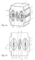
- FIG. 1a shows a heat exchanger with a first heat-conducting body 1 and a second, spaced vertically above the heat-conducting body 2.
- the two heat-conducting body 1, 2 have substantially the shape of a rectangular parallelepiped, the narrow end faces have a gradation 3, so that the width of the heat-conducting body 1, 2 is slightly reduced in the region of their opposite ends.
- the underside of the lower heat conducting body 1 forms a first planar contact surface 4, the upper side of the upper heat conducting body 2 a second planar contact surface 5.
- These contact surfaces 4, 5 are used to produce a planar contact to a (not shown) component from which heat is to be dissipated , or to a device, such as a housing cover that can absorb heat.
- the thermal gradient along the vertical axis of the heat exchanger causes a heat flow between the two contact surfaces 4, 5 from bottom to top or in the opposite direction, ie from top to bottom.
- each of the contact surfaces 4, 5 opposite sides of the heat conducting body 1, 2 are each two pairs of sliding surfaces 6a, 6b and 7a, 7b formed.
- the sliding surfaces 6a, 6b of the lower bathleit stresses are arranged in the form of a V; the sliding surfaces 7a, 7b of the upper réelleleit stressess are also arranged V-shaped, the V however is upside down.
- the sliding surfaces 6a, 6b, 7a, 7b are arranged on the legs of a total of four isosceles triangles, wherein the Points of two triangles point in opposite directions, so that a total of two diamonds are formed.
- FIGS. 1a, 1b left spreader 8 comprises two wedges 10a, 10b with wedge tips facing away from each other and a spring 11 arranged between the wedges.
- the second spreader element 9 of the same design (in FIG. 1b right) also comprises two wedges 12a, 12b with diverging tips and an intermediate spring 13.
- the springs 11, 13 designed as helical springs push apart the associated wedges 10a, 10 or 12a, 12b in the horizontal direction.
- the wedge surfaces 14 slide on the respectively associated sliding surfaces 6a, 6b of the lower heat conducting body 1 or on the sliding surfaces 7a, 7b of the upper heat conducting body 2.
- the wedge surfaces 14 and the associated sliding surfaces 6a, 6b and 7a, 7b run parallel, the means that they lie on the entire surface and almost no gap on each other.
- the wedges have 10a, 10b, 12a, 12b at their opposite the wedge tips backsides semi-circular grooves 15 in which strips 16 sit, whose cross section is also semicircular.
- the springs 11, 13 are supported against the flat tops of the strips 16.
- the strips 16 can twist slightly in the grooves 15 and thus compensate for a not exactly horizontal orientation of the heat-conducting body 1 and 2 against each other.
- the heat conducting body 1, 2 have at their mutually facing inner sides mirror-image shaped, but laterally offset slightly arranged guide webs 17, 18, which form a vertical guide for the heat conducting body 1, 2. At their free ends, the guide webs 17, 18 are angled outwards, whereby horizontal stops 19 and 20 are formed. These stops 19, 20 limit the way that the upper heat conducting body 2 can move away from the lower heat conducting body 1 in the vertical direction, wherein the guide webs 17, 18 move parallel and thus pretend a purely vertical displacement of the heat conducting body 1, 2 against each other.
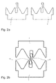
- FIG. 2a the two heat-conducting bodies 1, 2 are shown separately. They are manufactured in one piece from the same extruded profile.
- FIG. 2a are the two heat-conducting body 1, 2 arranged side by side, whereas FIG. 2b show the two heat-conducting body 1 and 2 pushed together.
- the upper heat conducting body 2 was rotated by 180 degrees on the lower heat conducting body 1 is pushed.
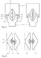
- FIG. 3 illustrates the function of the heat exchanger described above.
- the two heat-conducting bodies 1, 2 almost abut each other, so have a minimum distance, so that the entire device has minimal height.
- the two heat-conducting bodies 1, 2 have a maximum distance from each other in the vertical direction, so that the device has maximum height.
- the difference between minimum and maximum height gives the variable distance between two components (not shown) that can be connected by the device for the purpose of transferring heat.
- the springs 11, 13 ensure that a movement of the wedges 10a, 10b and 12a, 12b in the horizontal direction is converted into a vertical movement of the heat conducting body 1, 2 in the vertical direction against each other.
- the springs 11, 13 are maximally compressed, while they are almost completely relaxed in the left figure.
- the stops 19, 20 on the guide webs 17, 18 limit the vertical movement of the upper heat conducting body 2 relative to the lower heat conducting body. 1
- FIG. 4 show a second alternative embodiment of the heat exchanger.
- This device also comprises a lower heat-conducting body 1 and an upper heat-conducting body 2, which is arranged vertically above the first heat-conducting body 1 at a variable distance.
- the lower heat conducting body 1 is slightly narrower than the upper heat conducting body 2.
- a single expansion element 108 which is arranged between the two planteleit stresses 101, 102 and two horizontally movable wedges 110a, 110b, the wedge tips facing in opposite directions.
- FIG. 4 In the embodiment according to FIG. 4 are on the upper heat conducting body 2 right and left guide webs 118a, 118b integrally formed, which surround the lower heat-conducting body 1 laterally a piece.
- the guide webs 118a, 118b have at their free ends inwardly directed bends, which form stops 119a, 119b. These interact with counter-stops 120a, 120b on the lower heat-conducting body 101.
- the expansion element 108 is in principle the same design as the two expansion elements 8, 9 of the first embodiment of the heat exchanger (see. FIG. 1a, 1b ).
- the expansion element 108 comprises, in addition to the wedges 110a, 110b, a spring (not illustrated here) which presses the wedges 110a, 110b apart in the horizontal direction.
- FIG. 5 show a modified version of the spreading elements 8, 9 and 108.
- the wedges 210a, 210b have grooves here, which do not have a semicircular cross-section, but have a cross section in the form of an isosceles triangle with rounded tip.
- the ridges 216 seated in the grooves 215 also have a cross-section in the shape of an isosceles triangle, with the angle subtended by the legs of this triangle being slightly smaller than the corresponding angle of the grooves 215.
- the strips 216 can tilt by a corresponding angle. Thereby, a height offset between the left wedge 210a and the right wedge 210b can be compensated.
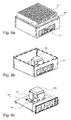
- FIGS. 6a, 6b and 6c illustrate the use of a heat transfer device 300 of the type previously described.
- FIG. 6a shows a closed housing 301 for installation of electronic components, in particular a Mini-ITX single board computer.
- the top of the cover 302 of the housing 301 is almost completely occupied by a heat sink 303, which has a plurality of cooling fins and thus has a large cooling surface.
- FIG. 6b the heat sink 303 is removed, so that the view into the interior of the housing 301 is free.
- FIG. 6c In addition, the side walls 304 are omitted, so that the motherboard 305 can be seen.
- a processor 306 the heat loss has to be dissipated.
- the heat transfer device 300 is mounted on the flat top of the processor 306.
- the lower heat-conducting body of the device 300 is covered by a mounting adapter 307. The movement of the upper heat-conducting body with respect to the lower heat-conducting body, which is firmly connected to the processor 306, is not obstructed by the mounting adapter 307.
Abstract
Eine Vorrichtung zur Übertragung von Wärme umfasst zwei massive Wärmeleitkörper (1, 2), die mit variablem Abstand vertikal übereinander angeordnet sind. Zwischen den Wärmeleitkörpern (1, 2) sitzt eines oder mehrere Spreizelemente (8, 9), welche jeweils zwei horizontal bewegbare Keile (10a, 10b, 12a, 12b) mit voneinander weg weisenden Keilspitzen umfasst sowie eine Feder (11, 12), welche die Keile auseinanderdrückt. Die Wärmeleitkörper (1, 2) haben korrespondierende Gleitflächen (6a, 6b, 7a, 7b), welche parallel zu den Keilflächen (14) verlaufen. Eine Bewegung der Keile (10a, 10b, 12a, 12b) in horizontaler Richtung wird in eine vertikale Bewegung der Wärmeleitkörper (1, 2) umgesetzt, wodurch sich die Höhe der gesamten Vorrichtung automatisch an die Einbausituation anpasst.A device for transmitting heat comprises two massive heat conducting bodies (1, 2), which are arranged vertically one above the other at a variable distance. Between the Wärmeleitkörpern (1, 2) sits one or more spreading elements (8, 9), each comprising two horizontally movable wedges (10a, 10b, 12a, 12b) facing away from each other wedge tips and a spring (11, 12), which wedge the wedges apart. The heat conducting bodies (1, 2) have corresponding sliding surfaces (6a, 6b, 7a, 7b) which run parallel to the wedge surfaces (14). A movement of the wedges (10a, 10b, 12a, 12b) in the horizontal direction is converted into a vertical movement of the heat conducting body (1, 2), whereby the height of the entire device automatically adapts to the installation situation.
Description
Die Erfindung betrifft eine Vorrichtung zur Übertragung von Wärme zwischen einer Wärmequelle und einer Wärmesenke durch Wärmeleitung. Ein solcher Wärmeübertrager wird insbesondere in der Industrieelektronik eingesetzt, um die Verlustleistung elektronischer Komponenten abzuleiten.The invention relates to a device for transferring heat between a heat source and a heat sink by heat conduction. Such a heat exchanger is used in particular in industrial electronics to derive the power loss of electronic components.
Elektronische Komponenten, wie zum Beispiel Mikroprozessoren, sitzen auf Leiterplatten, die in der Regel in ein Gehäuse eingebaut werden. Bei einem so genannten Singleboard Computer sind alle wesentlichen elektronischen Komponenten des Computers auf einer einzigen Leiterplatte, dem so genannten Motherboard angeordnet. Es besteht eine Tendenz zu immer kleineren Formaten, wie zum Beispiel dem standardisierten Mini-ITX mit einer Abmessung von 170 x 170 mm, in dessen Mitte ein leistungsfähiger Prozessor sitzt.Electronic components, such as microprocessors, sit on printed circuit boards, which are usually installed in a housing. In a so-called single-board computer all essential electronic components of the computer are arranged on a single circuit board, the so-called motherboard. There is a trend towards smaller and smaller formats, such as the standardized Mini-ITX with a dimension of 170 x 170 mm, in the middle of which sits a powerful processor.
Moderne Mehrkern-Prozessoren mit hoher Taktrate weisen eine so hohe thermische Verlustleistung auf, dass sie für einen sicheren Betrieb einer gezielten Kühlung bedürfen. Dies geschieht in der Regel mittels eines Kühlkörpers, der auf die plane Oberfläche des Prozessors aufgesetzt wird und eine Vielzahl von Kühlrippen aufweist, damit die Abwärme von einer großen Fläche durch Konvektion an die umgebende Luft abgeführt werden kann.Modern multi-core processors with a high clock rate have such a high thermal power loss that they require targeted cooling for safe operation. This is usually done by means of a heat sink, which is placed on the planar surface of the processor and a Having a plurality of cooling fins, so that the waste heat from a large area can be dissipated by convection to the surrounding air.
Für viele Anwendungszwecke müssen die elektronischen Komponenten eines Geräts in einem Gehäuse eingeschlossen werden, um es gegen Staub, Feuchtigkeit sowie Störstrahlungen zu schützen. Um dennoch die im Innern des Geräts erzeugte Abwärme nach außen abzuführen, kann das Gehäuse Lufteintritts- und Luftaustrittsöffnungen haben und/oder mit einem elektrischen Lüfter ausgestattet sein, welcher Kühlluft durch das Gehäuse hindurch bläst. In vielen Bereichen ist allerdings ein vollständig geschlossenes Gehäuse gefordert, um erhöhte Anforderungen an Staub- und Feuchtigkeitsschutz zu erfüllen.For many applications, the electronic components of a device must be enclosed in a housing to protect it against dust, moisture, and radiated emissions. In order nevertheless to dissipate the waste heat generated inside the device to the outside, the housing may have air inlet and outlet openings and / or be equipped with an electric fan, which blows cooling air through the housing. In many areas, however, a completely enclosed housing is required to meet increased requirements for dust and moisture protection.
Gehäuse für elektronische Geräte, insbesondere Industrie-Computer, mit höherer IP-Schutzklasse sind rundum dicht abgeschlossen, so dass keine Kühlluft mehr durch das Gehäuse hindurch geleitet werden kann. Stattdessen besitzen solche geschlossenen Gehäuse an ihren Außenseiten große Kühlkörper, die zum Beispiel als extrudierte Profilkörper ausgeführt sind. Es stellt sich hier das Problem, die elektronischen Komponenten im Innern des Gehäuses, also insbesondere den Prozessor oder die Prozessoren thermisch mit den Kühlkörpern an der Außenseite des Gehäuses zu verbinden, so dass die Verlustwärme durch Wärmeleitung zu den Kühlkörpern transportiert und dort durch Konvektion und/oder Wärmestrahlung an die Umgebung abgegeben werden kann.Enclosures for electronic devices, especially industrial computers, with higher IP protection class are sealed all around, so that no cooling air can be passed through the housing. Instead, such closed housing on their outsides large heat sink, which are designed for example as extruded profile body. It raises the problem here, the electronic components inside the housing, so in particular the processor or processors to thermally connect to the heat sinks on the outside of the housing, so that the heat loss transported by conduction to the heat sinks and there by convection and / or heat radiation can be delivered to the environment.
Bekannt sind massive rechteckige Metallklötze, die mit der Unterseite auf den Prozessor aufgesetzt werden und mit ihrer Oberseite an der Innenseite einer Gehäusewand anliegen, um die Wärme vom Prozessor an die Gehäusewand zu übertragen. Ein Problem hierbei sind die relativ großen Toleranzen der elektronischen und mechanischen Komponenten, insbesondere also der Prozessoren und der Bauteile des Schutzgehäuses. Schon die Bauhöhe eines marktüblichen Prozessors hat eine typische Toleranz von bis zu 1 mm. An der Wärmeübergangsstelle wird deshalb oft ein elastisches oder pastöses Material verwendet, das sich durch gute Wärmeleitfähigkeit auszeichnet. Die Dicke der Schicht von Wärmeleitpaste muss allerdings möglichst klein gehalten werden, denn die Wärmeleitfähigkeit auch der besten verfügbaren Produkte liegt um Größenordnungen niedriger als die Wärmeleitfähigkeit von Metall zum Beispiel Aluminium. Wird auch das andere Ende des Metallklotzes mithilfe von Wärmeleitpasten in thermischen Kontakt mit der Gehäusewand gebracht, wird der Wärmewiderstand noch größer.Are known massive rectangular metal blocks, which are placed with the bottom of the processor and abut with its top on the inside of a housing wall to transfer the heat from the processor to the housing wall. A problem here are the relatively large tolerances of the electronic and mechanical components, in particular so the processors and the components of the protective housing. Even the height of a commercially available processor has a typical tolerance of up to 1 mm. At the heat transfer point is therefore often an elastic or pasty material used, which is characterized by good thermal conductivity. The thickness of the layer of thermal compound must, however, be kept as small as possible, because the thermal conductivity of even the best available products is orders of magnitude lower than the thermal conductivity of metal, for example aluminum. If the other end of the metal block is brought into thermal contact with the housing wall by means of heat-conducting pastes, the thermal resistance becomes even greater.
Bei der Konstruktion und Produktion und Produktion von standardisierten Kleingehäusen für Industriecomputer besteht eine weitere Problematik darin, dass zwar die Abmessungen der Leiterplatte festliegen, aber offen bleiben soll, welcher Prozessortyp verwendet wird. Unterschiedlich leistungsfähige Prozessoren verschiedener Hersteller wie Intel, AMD, ARM oder VIA unterscheiden sich nicht nur durch ihre elektronischen Parameter und unterschiedliche Verlustleistungen, sondern auch hinsichtlich ihrer geometrischen Abmessungen. Für diese Prozessoren werden zwar universell einsetzbare Kühlkörper und Wärmeübertrager angeboten, das hierzu erforderliche Montagematerial muss aber die Toleranzen für die gesamte Konstruktion ausgleichen. Die Toleranzen für die Dicke des Prozessors, des Sockels, des Kühlkörpers oder Übertragers und gegebenenfalls des Gehäuses summieren sich somit auf einen Wert in der Größenordnung von 2 mm oder sogar mehr. Allein mit Wärmeleitpaste oder sogenanntem gap-filler lassen sich derart große Toleranzen nicht mehr ausgleichen, wenn noch eine effektive Kühlung gewährleistet werden soll.In the design and production and production of standardized small cases for industrial computers, another problem is that while the dimensions of the circuit board are fixed, but should remain open, which type of processor is used. Differently powerful processors from different manufacturers such as Intel, AMD, ARM or VIA differ not only by their electronic parameters and different power losses, but also in terms of their geometric dimensions. Although universally applicable heat sinks and heat exchangers are offered for these processors, the assembly material required for this purpose must however compensate for the tolerances for the entire construction. The tolerances for the thickness of the processor, the socket, the heat sink or transformer and optionally the housing thus add up to a value of the order of 2 mm or even more. Solely with thermal grease or so-called gap filler, such large tolerances can no longer be compensated if effective cooling is still to be ensured.
Eine weitere Herausforderung in diesem Zusammenhang besteht darin, dass auch bei einem vollständig geschlossenen Gehäuse zumindest der obere Deckel abnehmbar sein soll, um gegebenenfalls an die eingeschlossene Elektronik heranzukommen. Wird nach einer Reparatur der Deckel wieder aufgesetzt, muss auch die Wärmeleitung zwischen Prozessor und Deckel wieder vollständig hergestellt werden. Wärmeleitpaste ist allerdings schlecht für eine mehrfache Verwendung geeignet.Another challenge in this context is that even with a completely closed housing, at least the upper lid should be removable in order to possibly get to the enclosed electronics. If the lid is replaced after a repair, the heat conduction between processor and lid must also be completely restored. Thermal grease, however, is poorly suited for multiple use.
Angesichts der geschilderten Problematik stellt sich die Aufgabe, eine verbesserte Wärmeleitvorrichtung zu schaffen, welche einen relativ großen Toleranzbereich ausgleichen kann und sich trotzdem durch maximale Wärmeleitfähigkeit auszeichnet.In view of the problem described, the object is to provide an improved heat conducting device, which can compensate for a relatively large tolerance range and is still characterized by maximum thermal conductivity.
Bei der Lösung der Aufgabe wird ausgegangen von einer Vorrichtung gemäß dem Oberbegriff des Patentanspruchs 1. Gelöst wird die Aufgabe durch die kennzeichnenden Merkmale des Patentanspruchs.In the solution of the problem is assumed by a device according to the preamble of
Der erfindungsgemäße Wärmeübertrager hat zwei massive Wärmeleitkörper, die mit variablem Abstand vertikal übereinander angeordnet sind. Zwischen den beiden Körpern sitzt wenigstens ein Spreizelement, das zwei horizontal bewegbare Keile umfasst. Die Keilspitzen weisen in entgegengesetzte Richtungen. Zwischen den Keilen ist mindestens eine Feder angeordnet, welche die Keile entlang einer horizontalen Achse auseinander drückt. Die Wärmeleitkörper haben an ihren zueinander weisenden Seiten korrespondierende Gleitflächen, die paarweise angeordnet sind. Die Keilflächen gleiten auf den Gleitflächen der Wärmeleitkörper derart, dass eine Bewegung der Keile in horizontaler Richtung in eine vertikale Bewegung der Wärmeleitkörper umgesetzt wird. Dabei verlaufen die Keilflächen stets parallel zu den Gleitflächen.The heat exchanger according to the invention has two massive heat conducting body, which are arranged vertically one above the other at a variable distance. Between the two bodies sitting at least one spreading element comprising two horizontally movable wedges. The wedge points point in opposite directions. Between the wedges at least one spring is arranged, which presses apart the wedges along a horizontal axis. The Wärmeleitkörper have on their sides facing each other corresponding sliding surfaces, which are arranged in pairs. The wedge surfaces slide on the sliding surfaces of the heat conducting body such that a movement of the wedges in the horizontal direction is converted into a vertical movement of the heat conducting body. The wedge surfaces always run parallel to the sliding surfaces.
Die Kraft der Feder, welche durch Druck auf den oberen Wärmeleitkörper kompensiert wird, sorgt dafür, dass die Keilflächen stets ohne nennenswerten Spalt an den Gleitflächen der Wärmeleitkörper anliegen. Trotzdem ist der vertikale Abstand zwischen den beiden Wärmeleitkörpern variabel, so dass sich die Höhe der Wärmeübertragungsvorrichtung automatisch an die baulichen Gegebenheiten anpasst, um zum Beispiel unterschiedlich hohe Prozessoren oder Fertigungstoleranzen des Gehäuses auszugleichen. Die Feder sorgt auch dafür, dass die Keile auf die Gleitflächen der Wärmeleitkörper gedrückt werden, so dass ein guter Wärmeübergang zwischen Keilen und Wärmeleitkörpern gewährleistet ist. Wärmeleitkörper und Keile ergänzen sich so zu einem fast vollständig massiven Körper mit minimalem Wärmewiderstand zwischen den außenliegenden Kontaktflächen.The force of the spring, which is compensated by pressure on the upper heat-conducting body, ensures that the wedge surfaces always rest without any appreciable gap on the sliding surfaces of the heat-conducting body. Nevertheless, the vertical distance between the two Wärmeleitkörpern is variable, so that the height of the heat transfer device automatically adapts to the structural conditions, for example, to compensate for different levels of processors or manufacturing tolerances of the housing. The spring also ensures that the wedges are pressed onto the sliding surfaces of the Wärmeleitkörper, so that a good heat transfer between wedges and Wärmeleitkörpern is guaranteed. Heat-conducting bodies and wedges complement each other to form an almost completely solid body with minimal thermal resistance between the outer contact surfaces.
Bevorzugt haben die Keile einen Querschnitt, bei dem die Keilflächen auf den Schenkeln eines gleichschenkligen Dreiecks liegen. Die Form der Keile ist damit symmetrisch in Bezug auf eine horizontale Achse, die quer zur Bewegungsrichtung der Wärmeleitkörper verläuft. Dadurch ergibt sich ein doppelter Hub in vertikaler Richtung als dies bei Verwendung von Keilen mit nur einer schrägen Keilfläche der Fall wäre. Grundsätzlich sind aber auch andere Querschnittsformen für die Keile denkbar, zum Beispiel die Form eines quer liegenden rechtwinkligen Dreiecks, bei dem dann eine, vorzugsweise die obere Keilfläche schräg und die andere Keilfläche parallel zur Horizontalen verläuft.Preferably, the wedges have a cross section in which the wedge surfaces lie on the legs of an isosceles triangle. The shape of the wedges is thus symmetrical with respect to a horizontal axis which is transverse to the direction of movement of the heat conducting body. This results in a double stroke in the vertical direction than would be the case with the use of wedges with only one inclined wedge surface. In principle, however, other cross-sectional shapes for the wedges are conceivable, for example, the shape of a transverse rectangular triangle, in which then one, preferably the upper wedge surface obliquely and the other wedge surface is parallel to the horizontal.
Um auf kurzem horizontalen Weg einen großen Hub in vertikaler Richtung zu erzielen, ist es zweckmäßig, die Keilflächen in einem stumpfen Winkel anzuordnen. Dies ist hier möglich, da die zu bewegenden Gewichte und damit die Reibungskräfte zwischen Keilflächen und Gleitflächen relativ gering sind. Sollte die Vorrichtung allerdings größere Abmessungen aufweisen, könnte eine Anordnung der Keilflächen in einem Winkel von weniger als 90 Grad vorteilhaft sein.In order to achieve a long stroke in the vertical direction on a short horizontal path, it is expedient to arrange the wedge surfaces at an obtuse angle. This is possible here because the weights to be moved and thus the frictional forces between wedge surfaces and sliding surfaces are relatively small. However, should the device have larger dimensions, placement of the wedge surfaces at an angle of less than 90 degrees could be advantageous.
Aus der dreieckigen Form der Keile und ihrer gegenläufigen Bewegung ergibt sich, dass die Paare von Gleitflächen an den Wärmeleitkörpern jeweils in Form eines großen V bzw. umgekehrten V angeordnet sind, wobei sich der Winkel zwischen zwei aneinanderstoßenden Gleitflächen und der Winkel zwischen den Keilflächen zu 180 Grad ergänzen. Somit verlaufen die Keilflächen immer parallel zu den Gleitflächen, was wichtig ist, um einen möglichst guten Wärmekontakt zwischen den Keilen und den Wärmeleitkörpern herzustellen. Die Umlenkung der Federkraft durch die Keile in die Vertikale sorgt dafür, dass die Keilflächen unabhängig von ihrer Stellung plan gegen die korrespondierenden Gleitflächen gepresst werden.From the triangular shape of the wedges and their opposite movement it follows that the pairs of sliding surfaces are arranged on the Wärmeleitkörpern respectively in the form of a large V and inverted V, wherein the angle between two abutting sliding surfaces and the angle between the wedge surfaces to 180 Complement degree. Thus, the wedge surfaces are always parallel to the sliding surfaces, which is important in order to produce the best possible thermal contact between the wedges and the Wärmeleitkörpern. The deflection of the spring force by the wedges in the vertical ensures that the wedge surfaces are pressed regardless of their position plan against the corresponding sliding surfaces.
Die zwischen den Keilen angeordnete Feder ist vorzugsweise als Schraubenfeder ausgebildet, wobei die Federachse in einer horizontalen Ebene durch die Keilspitze liegt. Bevorzugt wird man zwei oder mehr Federn parallel nebeneinander anordnen, um ein Verkanten der Keile zu verhindern. Sind die Keile und die Keilflächen symmetrisch zu beiden Seiten derselben horizontalen Ebene angeordnet, ergibt sich eine insgesamt symmetrische Anordnung, die Vorteile hinsichtlich der Kinematik bietet, insbesondere zu einer automatischen Zentrierung der Keile in dem durch je eine Gleitfläche der beiden Wärmeleitkörper gemeinsam gebildeten Lager bewirken. Ein Verkanten der Wärmeleitkörper wird dadurch verhindert.The arranged between the wedges spring is preferably formed as a helical spring, wherein the spring axis lies in a horizontal plane through the wedge tip. Preferably, two or more springs will be arranged side by side in parallel to prevent tilting of the wedges. If the wedges and the wedge surfaces are arranged symmetrically on both sides of the same horizontal plane, this results in an overall symmetrical arrangement which offers advantages with regard to kinematics, in particular to an automatic centering of the wedges in the bearings jointly formed by a respective sliding surface of the two heat conducting bodies. Tilting of the heat-conducting body is thereby prevented.
Die Wärmeleitkörper können durch eine Führung so miteinander verbunden sein, dass sie im Wesentlichen nur in vertikaler Richtung gegeneinander beweglich sind, seitlich jedoch nicht ausweichen können. Diese Vertikalführung kann vorteilhaft einen Anschlag haben, der die maximale gegenseitige Verschiebung der Wärmeleitkörper begrenzt. Auch bei vollständig entspannter Feder, also maximal möglichem Abstand der Wärmeleitkörper voneinander, wird dadurch ein Auseinanderfallen der Vorrichtung verhindert, die Montage wird vereinfacht.The heat-conducting body can be connected to each other by a guide so that they are substantially only movable in the vertical direction against each other, but can not escape laterally. This vertical guide can advantageously have a stop which limits the maximum mutual displacement of the heat conducting body. Even with completely relaxed Spring, so the maximum possible distance of the heat-conducting body from each other, thereby a falling apart of the device is prevented, the assembly is simplified.
Anstelle einer einzigen Spreizvorrichtung mit zwei Keilen und einer Feder können auch zwei gleich ausgebildete Spreizelemente horizontal nebeneinander angeordnet sein. In diesem Falle haben die beiden Wärmeleitkörper jeweils zwei Paare von V-förmig angeordneten Gleitflächen, auf denen die Keile je eines der beiden Spreizelemente gleiten. Insbesondere für etwas breitere Wärmeübertragungsvorrichtungen ist die Anordnung von zwei gleichen Spreizelementen vorteilhaft, da damit automatisch eine konstante Verspannung der beiden Wärmeleitkörper zueinander gewährleistet ist. Für noch breitere Vorrichtungen ist es auch denkbar, mehr als zwei Spreizelemente horizontal nebeneinander anzuordnen.Instead of a single spreading device with two wedges and a spring and two equally trained spreading elements can be arranged horizontally next to each other. In this case, the two Wärmeleitkörper each have two pairs of V-shaped sliding surfaces on which slide the wedges each one of the two expansion elements. In particular, for somewhat wider heat transfer devices, the arrangement of two equal expansion elements is advantageous because it automatically ensures a constant tension of the two heat-conducting body to each other. For even wider devices, it is also conceivable to arrange more than two spreading horizontally next to each other.
Die Wärmeleitkörper werden bevorzugt einstückig als Strangpressprofil hergestellt. Das Material ist vorzugsweise ein Metall mit sehr guter Wärmeleitfähigkeit, insbesondere Aluminium oder Kupfer. Auch die Keile können einstückig als Strangpressprofil aus demselben Material hergestellt werden.The heat-conducting body are preferably produced in one piece as an extruded profile. The material is preferably a metal with very good thermal conductivity, in particular aluminum or copper. The wedges can be made in one piece as an extruded profile of the same material.
Besonders vorteilhaft ist es, wenn beide Wärmeleitkörper aus dem gleichen Strangpressprofil hergestellt sind. Der obere Wärmeleitkörper unterscheidet sich dann von dem unteren Wärmeleitkörper allein dadurch, dass er um 180 Grad gedreht angeordnet ist. Da auch die Keile gleich ausgebildet sind, kann die gesamte Vorrichtung im Wesentlichen aus nur drei verschiedenen Teilen zusammengesetzt werden, nämlich aus zwei gleichen Wärmeleitkörpern, wenigstens zwei gleichen Keilen und einer Feder oder mehreren gleichen Federn. Die Vertikalführung für die Wärmeleitkörper mitsamt Anschlag kann dabei durch einstückig an die Wärmeleitkörper angeformte Stege ausgebildet werden, so dass auch hierfür keine weiteren Teile hergestellt werden müssen.It when the two heat conducting body are made of the same extruded profile is particularly advantageous. The upper heat-conducting body then differs from the lower heat-conducting body only in that it is arranged rotated by 180 degrees. Since the wedges are the same design, the entire device can be composed essentially of only three different parts, namely two identical heat conducting bodies, at least two identical wedges and a spring or more identical springs. The vertical guide for the heat conducting together with stop can be formed by integrally formed on the heat conducting body webs, so that no further parts must be made for this purpose.
Wenn hier von "horizontal" und "vertikal" gesprochen wird, so geschieht dies zur Bestimmung der Anordnung und Bewegungsrichtungen der einzelnen Bauelemente der Vorrichtung relativ zueinander, und nicht etwa zur Definition der absoluten Winkellage im Raum. Grundsätzlich ist es nämlich möglich, die erfindungsgemäße Wärmeübertragungsvorrichtung beliebig im Raum anzuordnen, also beispielsweise auch zwischen zwei vertikal oder schräg im Raum stehenden Flächen zweier Körper, zwischen denen Wärme übertragen werden soll. Prozessoren von Computern werden allerdings in der Regel so in ein Gehäuse eingebaut, dass ihre Oberseite, von der die Wärme abgeführt werden muss, tatsächlich ungefähr horizontal im Raum ausgerichtet ist, und dass insoweit die beiden Wärmeleitkörper der erfindungsgemäßen Vorrichtung auch real ungefähr vertikal übereinander angeordnet sind. Schutz beansprucht wird jedenfalls auch für Wärmeübertragungsvorrichtungen, bei denen zum Beispiel die Wärmeleitkörper entlang einer horizontalen Achse einander gegenüberstehen und dementsprechend die Keile des mindestens einen Spreizelements entlang einer vertikalen Achse - und damit rechtwinklig bzw. quer zur Bewegungsrichtung der Wärmeleitkörper - bewegbar sind, so dass eine Bewegung der Keile in vertikaler Richtung in eine horizontale Bewegung der Wärmeleitkörper umgesetzt wird.When it is spoken of "horizontal" and "vertical", this is done to determine the arrangement and directions of movement of each Components of the device relative to each other, and not for the definition of the absolute angular position in space. In principle, it is in fact possible to arrange the heat transfer device of the invention arbitrarily in space, so for example, between two vertically or obliquely in space surfaces of two bodies between which heat is to be transferred. However, processors of computers are usually installed in a housing so that their upper side, from which the heat has to be dissipated, is actually oriented approximately horizontally in the room, and that insofar the two heat-conducting bodies of the device according to the invention are also arranged approximately vertically above one another , Protection is claimed at least for heat transfer devices in which, for example, the heat conduction along a horizontal axis face each other and, accordingly, the wedges of the at least one expansion element along a vertical axis - and thus perpendicular or transversely to the direction of movement of the heat conducting body - are movable, so that a Movement of the wedges in the vertical direction is converted into a horizontal movement of the heat conducting body.
Zwei Ausführungsbeispiele der Erfindung werden nun anhand der beigefügten Zeichnungen im Detail erläutert. Es zeigen:
- Figur 1a
- eine erste Vorrichtung zur Übertragung von Wärme, in isometrischer Darstellung;
- Figur 1b
- die Vorrichtung von
Figur 1a , in Seitenansicht; - Figur 2a
- das Profil der Wärmeleitkörper der Vorrichtung von
Figur 1a ; - Figur 2b
- die beiden Wärmeleitkörper von
Figur 1a , zusammengesetzt; - Figur 3
- die Vorrichtung von
Figur 1a , in zusammengedrücktem bzw. auseinandergeschobenem Zustand; - Figur 4
- eine zweite alternative Vorrichtung zur Übertragung von Wärme, in zusammengedrücktem bzw. auseinandergeschobenem Zustand, jeweils in Seitenansicht;
Figur 5- eine Modifikation der Vorrichtung von
Figur 4 ; Figur - den Einbau einer Wärmeübertragungsvorrichtung gemäß
Figur 1a in einem Gehäuse, perspektivisch; - Figur 7
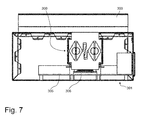
- das Gehäuse mit eingebauter Wärmeübertragungsvorrichtung gemäß
Figur 6a , in einem Vertikalschnitt.
- FIG. 1a
- a first device for transferring heat, in isometric view;
- FIG. 1b
- the device of
FIG. 1a , in side view; - FIG. 2a
- the profile of the heat conducting body of the device of
FIG. 1a ; - FIG. 2b
- the two heat-conducting body of
FIG. 1a , composed; - FIG. 3
- the device of
FIG. 1a , in a compressed or telescoped state; - FIG. 4
- a second alternative device for transmitting heat, in compressed or telescoped state, each in side view;
- FIG. 5
- a modification of the device of
FIG. 4 ; - Figure 6a, 6b, 6c
- the installation of a heat transfer device according to
FIG. 1a in a housing, in perspective; - FIG. 7
- the housing with built-in heat transfer device according to
FIG. 6a in a vertical section.
An den jeweils den Kontaktflächen 4, 5 gegenüberliegenden Seiten der Wärmeleitkörper 1, 2 sind jeweils zwei Paare von Gleitflächen 6a, 6b bzw. 7a, 7b ausgebildet. Die Gleitflächen 6a, 6b des unteren Wärmeleitkörpers sind in Form eines V angeordnet; die Gleitflächen 7a, 7b des oberen Wärmeleitkörpers sind ebenfalls V-förmig angeordnet, wobei das V allerdings auf dem Kopf steht. Dies bedeutet, dass die Gleitflächen 6a, 6b, 7a, 7b auf den Schenkeln von insgesamt vier gleichschenkligen Dreiecken angeordnet sind, wobei die Spitzen von jeweils zwei Dreiecken in entgegengesetzte Richtungen weisen, so dass insgesamt zwei Rauten gebildet werden.At each of the contact surfaces 4, 5 opposite sides of the
Zwischen den Wärmeleitkörpern 1, 2 sitzen zwei Spreizelemente 8 und 9, welche horizontal nebeneinander angeordnet sind. Das in den
Wie insbesondere aus dem Schnittbild von
Die Wärmeleitkörper 1, 2 weisen an ihren gegeneinander weisenden Innenseiten spiegelbildlich geformte, jedoch seitlich etwas versetzt angeordnete Führungsstege 17, 18 auf, welche eine vertikale Führung für die Wärmeleitkörper 1, 2 bilden. An ihren freien Enden sind die Führungsstege 17, 18 nach außen abgewinkelt, wodurch horizontale Anschläge 19 bzw. 20 gebildet werden. Diese Anschläge 19, 20 begrenzen den Weg, den sich der obere Wärmeleitkörper 2 vom unteren Wärmeleitkörper 1 in vertikaler Richtung entfernen kann, wobei sich die Führungsstege 17, 18 parallel verschieben und damit eine rein vertikale Verschiebung der Wärmeleitkörper 1, 2 gegeneinander vorgeben.The
In
Die zwei Schnittbilder von
Bei der Ausführungsform gemäß
Das Spreizelement 108 ist im Prinzip gleich ausgebildet wie die zwei Spreizelemente 8, 9 der ersten Ausführungsform des Wärmeübertragers (vgl.
Auch bei der Ausführung gemäß
Die Detailansichten von
Die
In
In
Aus dem Querschnitt von
- 11
- unterer Wärmeleitkörperlower heat-conducting body
- 22
- oberer WärmeleitkörperUpper heat-conducting body
- 33
- Abstufunggradation
- 44
- Kontaktfläche (von 1)Contact area (from 1)
- 55
- Kontaktfläche (von 2)Contact area (from 2)
- 6a, 6b6a, 6b
- Gleitflächen (von 1)Sliding surfaces (from 1)
- 7a, 7b7a, 7b
- Gleitflächen (von 2)Sliding surfaces (from 2)
- 88th
- Spreizelementspreader
- 99
- Spreizelementspreader
- 10a, 10b10a, 10b
- Keile (von 8)Wedges (from 8)
- 1111
- Feder (von 8)Feather (of 8)
- 12a, 12b12a, 12b
- Keile (von 9)Wedges (from 9)
- 1313
- Feder (von 9)Spring (from 9)
- 1414
- Keilflächen (von 8, 9)Wedge surfaces (from 8, 9)
- 1515
- Nutengroove
- 1616
- LeistenAfford
- 1717
- Führungssteg (von 1)Guide bar (from 1)
- 1818
- Führungssteg (von 2)Guide bar (from 2)
- 1919
- Anschlag (von 17)Stop (from 17)
- 2020
- Anschlag (von 18)Stop (from 18)
- 101101
- unterer Wärmeleitkörperlower heat-conducting body
- 102102
- oberer WärmeleitkörperUpper heat-conducting body
- 108108
- Spreizelementspreader
- 110a, 110b110a, 110b
- Keile (von 108)Wedges (from 108)
- 118a, 118b118a, 118b
- Führungsstegeguide webs
- 119a, 119b119a, 119b
- Anschlägeattacks
- 120a, 120b120a, 120b
- Gegenanschlägeagainst attacks
- 210a, 210b210a, 210b
- Keilewedges
- 211211
- Federfeather
- 215215
- Nutengroove
- 216216
- LeistenAfford
- 300300
- WärmeübertragungsvorrichtungHeat transfer device
- 301301
- Gehäusecasing
- 302302
- Deckelcover
- 303303
- Kühlkörperheatsink
- 304304
- Seitenwändeside walls
- 305305
- Motherboardmotherboard
- 306306
- Prozessorprocessor
- 307307
- Montageadaptermounting adapter
Claims (10)
zwei massiven Wärmeleitkörpern (1, 2; 101, 102), die mit variablem Abstand vertikal übereinander angeordnet sind,
einem federelastischen Element, durch das die beiden Wärmeleitkörper (1,2; 101, 102) auseinander gedrückt werden,
dadurch gekennzeichnet, dass
zwischen den Wärmeleitkörpern (1, 2; 101, 102) wenigstens ein Spreizelement (8, 9; 108) sitzt, das zwei horizontal bewegbare Keile (10a, 10b, 12a, 12b; 110a, 110b) mit voneinander weg weisenden Keilspitzen umfasst sowie mindestens eine zwischen den Keilen angeordnete Feder (11, 13), welche die Keile auseinander drückt,
die Wärmeleitkörper (1, 2; 101, 102) an ihren zueinander weisenden Seiten jeweils mindestens ein Paar von Gleitflächen (6a, 6b; 7a, 7b) haben, welche parallel zu den Keilflächen (14) verlaufen und auf denen die Keile (10a, 10b, 12a, 12b; 110a, 110b) gleiten, so dass eine Bewegung der Keile in horizontaler Richtung in eine vertikale Bewegung der Wärmeleitkörper umgesetzt wird.Device for transferring heat, with
two massive heat conducting bodies (1, 2; 101, 102), which are arranged vertically one above the other at a variable distance,
a spring-elastic element, by which the two heat-conducting bodies (1, 2, 101, 102) are pressed apart,
characterized in that
at least one expansion element (8, 9; 108) is seated between the heat-conducting bodies (1, 2; 101, 102) and comprises two horizontally movable wedges (10a, 10b, 12a, 12b; 110a, 110b) with wedge tips facing away from each other and at least a spring (11, 13) arranged between the wedges, which presses apart the wedges,
the heat conducting bodies (1, 2; 101, 102) each have at least one pair of sliding surfaces (6a, 6b; 7a, 7b) on their mutually facing sides which run parallel to the wedge surfaces (14) and on which the wedges (10a, 10b, 12a, 12b, 110a, 110b), so that movement of the wedges in the horizontal direction is converted into vertical movement of the heat conducting bodies.
zwei Spreizelemente (8, 9) horizontal nebeneinander angeordnet sind,
die beiden Wärmeleitkörper (1, 2) jeweils zwei Paare von V-förmig angeordneten Gleitflächen (6a, 6b, 7a, 7b) haben.Device according to one of the preceding claims, characterized in that
two spreading elements (8, 9) are arranged horizontally next to one another,
the two heat-conducting bodies (1, 2) each have two pairs of V-shaped sliding surfaces (6a, 6b, 7a, 7b).
Priority Applications (4)
| Application Number | Priority Date | Filing Date | Title |
|---|---|---|---|
| EP14185527.0A EP2999320A1 (en) | 2014-09-19 | 2014-09-19 | Device for transferring heat |
| EP15158736.7A EP2999322B1 (en) | 2014-09-19 | 2015-03-12 | Device for transferring heat |
| US14/857,127 US9863717B2 (en) | 2014-09-19 | 2015-09-17 | Heat transferring device |
| CN201510596712.9A CN105451514B (en) | 2014-09-19 | 2015-09-18 | heat transfer apparatus |
Applications Claiming Priority (1)
| Application Number | Priority Date | Filing Date | Title |
|---|---|---|---|
| EP14185527.0A EP2999320A1 (en) | 2014-09-19 | 2014-09-19 | Device for transferring heat |
Publications (1)
| Publication Number | Publication Date |
|---|---|
| EP2999320A1 true EP2999320A1 (en) | 2016-03-23 |
Family
ID=51584990
Family Applications (2)
| Application Number | Title | Priority Date | Filing Date |
|---|---|---|---|
| EP14185527.0A Withdrawn EP2999320A1 (en) | 2014-09-19 | 2014-09-19 | Device for transferring heat |
| EP15158736.7A Active EP2999322B1 (en) | 2014-09-19 | 2015-03-12 | Device for transferring heat |
Family Applications After (1)
| Application Number | Title | Priority Date | Filing Date |
|---|---|---|---|
| EP15158736.7A Active EP2999322B1 (en) | 2014-09-19 | 2015-03-12 | Device for transferring heat |
Country Status (3)
| Country | Link |
|---|---|
| US (1) | US9863717B2 (en) |
| EP (2) | EP2999320A1 (en) |
| CN (1) | CN105451514B (en) |
Cited By (1)
| Publication number | Priority date | Publication date | Assignee | Title |
|---|---|---|---|---|
| US20170363371A1 (en) * | 2016-06-15 | 2017-12-21 | Mellanox Technologies Ltd. | Self-adjusting cooling module |
Families Citing this family (3)
| Publication number | Priority date | Publication date | Assignee | Title |
|---|---|---|---|---|
| CN107087377B (en) * | 2017-04-28 | 2019-04-26 | 华为技术有限公司 | Radiator, radiator, electronic equipment and radiating control method |
| CN108415525B (en) * | 2018-03-23 | 2019-12-31 | 温岭市志创网络科技有限公司 | Computer casing with improved structure |
| TWI824910B (en) * | 2023-01-03 | 2023-12-01 | 凌華科技股份有限公司 | Elastic thermally conductive components for electronic devices |
Citations (4)
| Publication number | Priority date | Publication date | Assignee | Title |
|---|---|---|---|---|
| US20070019384A1 (en) * | 2005-07-19 | 2007-01-25 | Bae Systems Information | Cold plate cooling apparatus for a rack mounted electronic module |
| US20070030656A1 (en) | 2005-08-08 | 2007-02-08 | Verifone Holdings, Inc. | Thermal transfer device |
| US20090229808A1 (en) * | 2008-03-17 | 2009-09-17 | Chung-Jun Chu | Heat-conducting assembly |
| WO2013135595A1 (en) * | 2012-03-15 | 2013-09-19 | Ecrin Systems | Processor and radiator for this processor |
Family Cites Families (9)
| Publication number | Priority date | Publication date | Assignee | Title |
|---|---|---|---|---|
| JPH063831B2 (en) * | 1987-04-08 | 1994-01-12 | 株式会社日立製作所 | Cooling device and semiconductor device using the same |
| EP0354722A3 (en) * | 1988-08-08 | 1991-04-03 | Hitachi, Ltd. | Heat transfer system especially for cooling semiconductor devices |
| US5184281A (en) * | 1992-03-03 | 1993-02-02 | Digital Equipment Corporation | Heat dissipation apparatus |
| DE69401040T2 (en) * | 1993-07-12 | 1997-06-05 | Nec Corp | Housing structure for microwave switching |
| US6985359B2 (en) * | 2003-04-21 | 2006-01-10 | Hewlett-Packard Development Company, L.P. | Variable-wedge thermal-interface device |
| US7120023B2 (en) * | 2003-08-25 | 2006-10-10 | Hewlett-Packard Development Company, L.P. | Method of assembly of a wedge thermal interface to allow expansion after assembly |
| CN101193536A (en) * | 2006-11-29 | 2008-06-04 | 英业达股份有限公司 | Heat radiator structure and its assembly tool |
| CN102131371B (en) * | 2010-11-11 | 2014-03-26 | 华为技术有限公司 | Heat-conducting device and electronic device using same |
| WO2012166122A1 (en) * | 2011-05-31 | 2012-12-06 | Aavid Thermalloy, Llc | Heat sink mount with positionable heat sinks |
-
2014
- 2014-09-19 EP EP14185527.0A patent/EP2999320A1/en not_active Withdrawn
-
2015
- 2015-03-12 EP EP15158736.7A patent/EP2999322B1/en active Active
- 2015-09-17 US US14/857,127 patent/US9863717B2/en active Active
- 2015-09-18 CN CN201510596712.9A patent/CN105451514B/en not_active Expired - Fee Related
Patent Citations (4)
| Publication number | Priority date | Publication date | Assignee | Title |
|---|---|---|---|---|
| US20070019384A1 (en) * | 2005-07-19 | 2007-01-25 | Bae Systems Information | Cold plate cooling apparatus for a rack mounted electronic module |
| US20070030656A1 (en) | 2005-08-08 | 2007-02-08 | Verifone Holdings, Inc. | Thermal transfer device |
| US20090229808A1 (en) * | 2008-03-17 | 2009-09-17 | Chung-Jun Chu | Heat-conducting assembly |
| WO2013135595A1 (en) * | 2012-03-15 | 2013-09-19 | Ecrin Systems | Processor and radiator for this processor |
Cited By (2)
| Publication number | Priority date | Publication date | Assignee | Title |
|---|---|---|---|---|
| US20170363371A1 (en) * | 2016-06-15 | 2017-12-21 | Mellanox Technologies Ltd. | Self-adjusting cooling module |
| US10054375B2 (en) * | 2016-06-15 | 2018-08-21 | Mellanox Technologies, Ltd. | Self-adjusting cooling module |
Also Published As
| Publication number | Publication date |
|---|---|
| CN105451514A (en) | 2016-03-30 |
| CN105451514B (en) | 2018-05-08 |
| EP2999322A1 (en) | 2016-03-23 |
| US9863717B2 (en) | 2018-01-09 |
| EP2999322B1 (en) | 2016-11-23 |
| US20160084590A1 (en) | 2016-03-24 |
Similar Documents
| Publication | Publication Date | Title |
|---|---|---|
| EP2999322B1 (en) | Device for transferring heat | |
| DE112017005498B4 (en) | Semiconductor device and method of manufacturing the same | |
| EP3541157B1 (en) | Electronic assembly comprising a housing with cooling fins | |
| DE102017129357A1 (en) | HEAT SINK | |
| DE3223624C2 (en) | Heat sinks for electrical components | |
| DE202014010648U1 (en) | Cooling device for cooling an electronic component and electronic assembly with a cooling device | |
| DE112011101941B4 (en) | Method for constructing a heat exchanger and heat exchanger device | |
| DE202014104475U1 (en) | Device for transferring heat | |
| DE102015111298B3 (en) | Housing for an electrical device and arrangement comprising such a housing with an electrical device disposed therein | |
| DE102018120657A1 (en) | COOLING STRUCTURE FOR A ROBOT MOTOR | |
| EP3230673B1 (en) | Heat transferring compensating element and electrically operatable vehicle having such a compensating element | |
| AT520072B1 (en) | Heat sink and vehicle headlights | |
| EP3223998B1 (en) | Device for machining a planar workpiece | |
| DE3219571A1 (en) | Housing for electronic circuits | |
| DE102005035387B4 (en) | Heatsink for a module pluggable into a slot in a computer system, and module, system and computer with the same and method for cooling a module | |
| DE202010007905U1 (en) | Wärmeleitelement, arrangement and use of the same | |
| WO2017215930A1 (en) | Electrohydraulic actuating device with cooling modules | |
| EP1750302B1 (en) | Arrangement of electrical elements | |
| DE102015204915A1 (en) | Wärmeleitkörper with a coupling surface with recess and heat transfer device | |
| DE102017216598A1 (en) | Heat sink and method of manufacturing a heat sink | |
| EP4090145A1 (en) | Cooling device for dissipating heat | |
| DE202022106450U1 (en) | radiant heater | |
| WO2023134815A1 (en) | Cooling body having a heat pipe for an electronic component, and corresponding assembly | |
| EP3113220A1 (en) | Cooling element | |
| DE102017103200A1 (en) | Cooling device for passive cooling of a computer system and computer system |
Legal Events
| Date | Code | Title | Description |
|---|---|---|---|
| PUAI | Public reference made under article 153(3) epc to a published international application that has entered the european phase |
Free format text: ORIGINAL CODE: 0009012 |
|
| AK | Designated contracting states |
Kind code of ref document: A1 Designated state(s): AL AT BE BG CH CY CZ DE DK EE ES FI FR GB GR HR HU IE IS IT LI LT LU LV MC MK MT NL NO PL PT RO RS SE SI SK SM TR |
|
| AX | Request for extension of the european patent |
Extension state: BA ME |
|
| STAA | Information on the status of an ep patent application or granted ep patent |
Free format text: STATUS: THE APPLICATION IS DEEMED TO BE WITHDRAWN |
|
| 18D | Application deemed to be withdrawn |
Effective date: 20160924 |