EP3113220A1 - Cooling element - Google Patents
Cooling element Download PDFInfo
- Publication number
- EP3113220A1 EP3113220A1 EP16178495.4A EP16178495A EP3113220A1 EP 3113220 A1 EP3113220 A1 EP 3113220A1 EP 16178495 A EP16178495 A EP 16178495A EP 3113220 A1 EP3113220 A1 EP 3113220A1
- Authority
- EP
- European Patent Office
- Prior art keywords
- cooling
- heat sink
- base plate
- cooling air
- cooling fins
- Prior art date
- Legal status (The legal status is an assumption and is not a legal conclusion. Google has not performed a legal analysis and makes no representation as to the accuracy of the status listed.)
- Granted
Links
Images


Classifications
-
- H—ELECTRICITY
- H01—ELECTRIC ELEMENTS
- H01L—SEMICONDUCTOR DEVICES NOT COVERED BY CLASS H10
- H01L23/00—Details of semiconductor or other solid state devices
- H01L23/34—Arrangements for cooling, heating, ventilating or temperature compensation ; Temperature sensing arrangements
- H01L23/36—Selection of materials, or shaping, to facilitate cooling or heating, e.g. heatsinks
- H01L23/367—Cooling facilitated by shape of device
- H01L23/3672—Foil-like cooling fins or heat sinks
-
- F—MECHANICAL ENGINEERING; LIGHTING; HEATING; WEAPONS; BLASTING
- F28—HEAT EXCHANGE IN GENERAL
- F28F—DETAILS OF HEAT-EXCHANGE AND HEAT-TRANSFER APPARATUS, OF GENERAL APPLICATION
- F28F13/00—Arrangements for modifying heat-transfer, e.g. increasing, decreasing
- F28F13/06—Arrangements for modifying heat-transfer, e.g. increasing, decreasing by affecting the pattern of flow of the heat-exchange media
- F28F13/08—Arrangements for modifying heat-transfer, e.g. increasing, decreasing by affecting the pattern of flow of the heat-exchange media by varying the cross-section of the flow channels
-
- F—MECHANICAL ENGINEERING; LIGHTING; HEATING; WEAPONS; BLASTING
- F28—HEAT EXCHANGE IN GENERAL
- F28F—DETAILS OF HEAT-EXCHANGE AND HEAT-TRANSFER APPARATUS, OF GENERAL APPLICATION
- F28F3/00—Plate-like or laminated elements; Assemblies of plate-like or laminated elements
- F28F3/02—Elements or assemblies thereof with means for increasing heat-transfer area, e.g. with fins, with recesses, with corrugations
-
- H—ELECTRICITY
- H01—ELECTRIC ELEMENTS
- H01L—SEMICONDUCTOR DEVICES NOT COVERED BY CLASS H10
- H01L21/00—Processes or apparatus adapted for the manufacture or treatment of semiconductor or solid state devices or of parts thereof
- H01L21/02—Manufacture or treatment of semiconductor devices or of parts thereof
- H01L21/04—Manufacture or treatment of semiconductor devices or of parts thereof the devices having at least one potential-jump barrier or surface barrier, e.g. PN junction, depletion layer or carrier concentration layer
- H01L21/48—Manufacture or treatment of parts, e.g. containers, prior to assembly of the devices, using processes not provided for in a single one of the subgroups H01L21/06 - H01L21/326
- H01L21/4814—Conductive parts
- H01L21/4871—Bases, plates or heatsinks
- H01L21/4882—Assembly of heatsink parts
-
- H—ELECTRICITY
- H01—ELECTRIC ELEMENTS
- H01L—SEMICONDUCTOR DEVICES NOT COVERED BY CLASS H10
- H01L23/00—Details of semiconductor or other solid state devices
- H01L23/34—Arrangements for cooling, heating, ventilating or temperature compensation ; Temperature sensing arrangements
- H01L23/46—Arrangements for cooling, heating, ventilating or temperature compensation ; Temperature sensing arrangements involving the transfer of heat by flowing fluids
- H01L23/467—Arrangements for cooling, heating, ventilating or temperature compensation ; Temperature sensing arrangements involving the transfer of heat by flowing fluids by flowing gases, e.g. air
-
- H—ELECTRICITY
- H01—ELECTRIC ELEMENTS
- H01L—SEMICONDUCTOR DEVICES NOT COVERED BY CLASS H10
- H01L2924/00—Indexing scheme for arrangements or methods for connecting or disconnecting semiconductor or solid-state bodies as covered by H01L24/00
- H01L2924/0001—Technical content checked by a classifier
- H01L2924/0002—Not covered by any one of groups H01L24/00, H01L24/00 and H01L2224/00
Definitions
- the present invention relates to a heat sink for at least one component to be cooled, in particular a semiconductor component, according to the preamble of claim 1 and a heat sink for at least one component to be cooled, in particular a semiconductor component, according to the preamble of claim.
- Generic heat sink for cooling in particular electronic high-performance components such as IGBT modules for power converters, for example, known from the DE 10 2006 019 376 A1 , of the DE 43 22 647 A1 or the DE 93 04 128 U1 serve to dissipate the heat generated by these components and thereby cool the components.
- the heat sinks are usually made of a base plate on which one or more of these components are applied flat, and one of these device surface facing away from the heat sink surface, extending from the cooling air ducts forming cooling fins away.
- These cooling fins are embedded in a variant in grooves of a base plate, for example, formed as an extruded profile, so that the heat generated by the components is passed through the base plate in the cooling fins and the cooling fins in turn to form the above-mentioned cooling air channels with passage of cooling air through the heat sink deliver this heat to the passing cooling air.
- the pressure loss of the cooling air should be as low as possible when passing through the heat sink.
- the cooling capacity of the heat sink should be as constant as possible in the cooling air flow direction through the heat sink in order to be able to cool the rear components even when the components to be cooled are built one behind the other, for example in the cooling air flow direction.
- Object of the present invention is to provide a heat sink with which the above problems are solved as effectively and inexpensively.
- the structure of a heat sink claimed in claim 1 consists essentially of a plurality of juxtaposed, cooling air ducts forming cooling fins, which form a base plate with respective first ends, wherein at least some of the cooling fins have a thickened relative to a cooling air ducts forming the first end, wherein a part the cooling fins are formed as an extruded profile and the other cooling fins as separating plates, wherein the extruded profiles and the separating plates are soldered one behind the other.
- a cooling body which can be produced cost-effectively is provided, in which the base plates composed of the thickened ends of the cooling fins form a good heat-conducting base plate as a result of the soldering.
- Such a heat sink can also be assembled in a simple and cost-effective manner into a block and solder, whereby the heat sink can be made very variable in size, since the production of a heat sink greater length or width can be realized in a simple manner that more or less extrusion ribs and dividers are joined together.
- tools having the desired width usually have to be produced, which entails greater production costs.
- such a heat sink extending in the cooling air flow direction webs are formed in the cooling air channels forming portion of the formed as an extruded profile fins which abut against respective side surfaces of the cooling fins formed as partitions and so good heat exchange between the formed as extruded cooling fins and allow the cooling ribs designed as partitions.
- These webs are preferably integrally formed on both sides of the cooling air ducts forming region.
- the webs are formed by a half distance in which the webs are formed parallel to each other on one side of the extruded profile, mutually offset from each other formed on the formed as an extruded cooling fins.
- the length of the webs perpendicular to the cooling air flow direction is greater than half the difference of the thickness of the thickened end of the formed as an extruded cooling fins and the thickness of the cooling air ducts forming portion of the formed as an extruded cooling fins, so that when assembling the heat sink, the baffles slightly be deformed and thus even with manufacturing tolerances of the extruded sections and the spacer ribs a mechanical system of the webs is ensured to the dividing plates and thus a heat-conductive connection can be generated.
- the cooling air ducts forming portions of the cooling fins formed as partitions in the cooling air inlet region of the heat sink are at least partially cut away, which, as already described above, allows an advantageous reduction of the pressure loss of the cooling air as it flows through the heat sink.
- the claimed claim 7 alternative structure of a heat sink has a first base plate with a component surface on which the at least one component to be cooled can be fastened, and a reversed heat sink surface and a plurality of cooling air ducts forming cooling fins having respective first ends on the heat sink surface of the first base plate are attached.
- the first ends of the cooling fins are received in groove-shaped receptacles of a sheet soldered on both sides on the heat sink surface of the first base plate, wherein the cooling fins, the sheet metal and the first base plate are soldered together.
- a heat sink formed in this way is characterized by its cost-effective manufacturability.
- sufficient bonding surface is available in order to ensure reliable bonding between the cooling ribs, the metal sheet and the baseplate.
- solder paste Another problem with this method is to dose solder in an appropriate amount to the joints. Both sides clad ribs contain too much solder. The problem with such a solder paste is that outgassing binder during soldering and dirty the soldering, which is associated with additional costs to eliminate them.
- the heat sink according to claim 7 is preferably provided with a sheet which is formed with open to the heat sink surface of the first base plate channels between the groove-shaped receptacles, which are filled in operation with a refrigerant.
- the second ends of the cooling fins are also received in groove-shaped receptacles of a sheet soldered on both sides on the heat sink surface of a second base plate, wherein the cooling fins, the metal sheet and the second base plate are soldered together.
- the two base plates are preferably connected to each other by two pipe or hose connections that allow a refrigerant transport.
- the refrigerant is condensed and heat in an upper area transferred to the cooling fins. Since heat is transferred from both sides into the cooling fins in the upper area, the fin efficiency is significantly increased and the heat transfer significantly increased.
- the cooling fins do not form over the entire length of the heat sink, but only in the area in which condensation takes place, for example, over half the length of the heat sink.
- top, bottom, left, right, front, back, etc. refer exclusively to the exemplary representation and position of the heat sink, the base plate, cooling fins, cooling air channels, webs and the like selected in the respective figures. These terms are not meant to be limiting, i. h., Through different working positions or the mirror-symmetrical design or the like, these references may change.
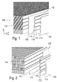
- a first embodiment of a heat sink 100 according to the invention is in the FIGS. 1 to 4 shown.
- the cooling body 100 consists in this embodiment substantially of a plurality of adjacent cooling air channels 140 forming cooling fins 110, 130, which form a base plate with respective first ends 111, 131, wherein at least some of the cooling fins 110, 130 with respect to a cooling air channels 140 forming areas 112 thickened in the cooling air flow direction x extending first end 111 or edge region.
- the cooling fins 110, 130 are partially formed as extruded profiles and partially as partitions, which are soldered together.
- the cooling fins 130 designed as separating plates are in this case preferably in the form of sheets solder-plated on both sides.
- the base plate forming thickened ends 111 are formed on the cooling ribs 110 formed as an extruded profile.
- cooling air flow direction x extending webs 113, 114 in the cooling air channels 140 forming portion 112 of the cooling fins 110 on the cooling fins formed as an extruded profile 110, which abut against respective side surfaces of the cooling fins 130 formed as partitions, so that as Extruded profiles formed cooling ribs 110 in the region of the webs 113, 114 are also soldered to the cooling fins 130 formed as partitions.
- These webs 113, 114 are preferably on both sides of the cooling air channels 140 forming region 112 of the extruded profile designed as cooling fins 110 provided and serve in addition to the heat transfer in addition to uniform distances between the individual cooling fins 110, 130 rö to ge discourse.
- a plurality of webs 113, 114 are preferably integrally formed at a distance a from each other at the side surfaces of the cooling ribs 110.
- the length I 113 , I 114 of these webs perpendicular to the cooling air flow direction x in the direction of the width y of the heat sink 100 is preferably greater than half the difference between the thickness d 111 of the thickened end 111 of the formed as extruded cooling fins 110 and the thickness d 112th.
- cooling fins 130 may be cut differently in the cooling air flow direction x and / or be arranged cut and not cut dividers alternately.
- both the lower end of the formed as extruded cooling fins 110 and the upper end 115 are formed thickened, so that with such formed cooling fins 110, 130, a heat sink 100 with an upper and a lower base plate can be produced.
- the base plate or base plates are made of cohesive connections between the individual cooling fins 110, 130, which provide a very good heat transfer and are mechanically very robust.
- cooling fins 130 constructed as partitions in this variant can be produced very inexpensively by simply punching out a desired region of the partitions.
- the cooling fins 230 are received with their first ends 231 in groove-shaped receptacles 221 of a metal sheet soldered on both sides on the heat sink surface 212 of the first base plate 210.
- the cooling fins 230, the sheet 220 and the first base plate 210 are soldered together, in particular induction soldered.
- the sheet has open channels 223 between the groove-shaped receptacles 221 for receiving the cooling fins 230 relative to the cooling body surface 212 of the first base plate 210.
- These channels 223 are filled with a refrigerant in the operation of the heat sink, which circulates in the channels 223 due to density differences caused by unit state changes of the refrigerant associated with different temperatures. This allows a further improved removal of the waste heat of the component 1 to be cooled.
- refrigerant while a fluid is called, which absorbs heat at low temperature and low pressure and releases heat at a higher temperature and pressure.
- refrigerants are used for example in heat pipes (also called “heat pipes”) or in compression heat pumps.
- the sheet 220 is preferably deformed like a lamella, in particular stamped or rolled.
- the supply of the refrigerant is preferably carried out via a in the base plate 210 to the plate 220 toward open groove 213, which extends transversely to the channels 223 of the plate 220.
- the groove 213 is connected at one side edge of the base plate 210 with a feed element, such as a pipe piece or a hose 250, by the coolant in the groove 213 and the channels 223 can be removed or discharged.
- the channels 223 are preferably frontally sealed by a sealing element 260 extending along the front edges of the sheet 220 along.
- the seal is preferably carried out by welding. Accordingly, the sealing member 260 is in the in FIG. 6 shown embodiment designed as a weld
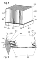
- FIG. 7 shows a variant of a heat sink according to the invention with two base plates 210, 270, wherein on the first base plate 210 to be cooled body 1 is mounted.
- the two base plates 210, 270 are connected to each other by a pipe section 251. These pipe sections 251 open into the grooves 213 of the base plates 210, 270. Through these connecting elements 251, the refrigerant can flow from the first base plate into the second base plate 270.
- the refrigerant will condense in the channels 223 and thus transfer heat to the cooling fins 230.
- the efficiency of the fin is significantly increased, thereby significantly increasing heat transfer.
- two such grooves 213 are preferably provided in the base plates 210, 270.
- the two grooves 213 are preferably spaced as far as possible from each other.
- the cooling fins 230 do not extend over the entire length of the heat sink 2, but extend only in an area on which a Condensation of the refrigerant takes place, in particular over half the length of the heat sink 2.
- the heat sink 2 can preferably according to the basis of FIG. 6 be executed embodiment described.
Abstract
Ein Kühlkörper (2) für mindestens ein zu kühlendes Bauelement (1), insbesondere ein Halbleiterbauelement, weist mehrere nebeneinander angeordnete, Kühlluftkanäle (140) bildende Kühlrippen (110, 130) auf, die mit jeweiligen ersten Enden (41, 51) eine Grundplatte bilden, wobei zumindest einige der Kühlrippen (110, 130) ein gegenüber einem die Kühlluftkanäle (140) bildenden Bereich (112) verdicktes erstes Ende (111) aufweisen, wobei ein Teil der Kühlrippen (110) als Strangpressprofil und die übrigen Kühlrippen (130) als Trennbleche ausgebildet sind, wobei die Strangpressprofile und die Trennbleche (130) miteinander verlötet sind. Desweiteren wird eine alternative Variante eines Kühlkörpers beschrieben.A heat sink (2) for at least one component (1) to be cooled, in particular a semiconductor component, has a plurality of cooling fins (110, 130) forming cooling air channels (140) arranged side by side and forming a base plate with respective first ends (41, 51) in that at least some of the cooling ribs (110, 130) have a first end (111) thickened relative to a region (112) forming the cooling air ducts (140), part of the cooling ribs (110) being extruded and the remaining cooling ribs (130) being Dividing plates are formed, wherein the extruded profiles and the separating plates (130) are soldered together. Furthermore, an alternative variant of a heat sink is described.
Description
Die vorliegende Erfindung betrifft einen Kühlkörper für mindestens ein zu kühlendes Bauelement, insbesondere ein Halbleiterbauelement, gemäß dem Oberbegriff des Anspruchs 1 sowie einen Kühlkörper für mindestens ein zu kühlendes Bauelement, insbesondere ein Halbleiterbauelement, gemäß dem Oberbegriff des Anspruchs 7.The present invention relates to a heat sink for at least one component to be cooled, in particular a semiconductor component, according to the preamble of
Gattungsgemäße Kühlkörper zur Kühlung von insbesondere elektronischen Hochleistungsbauteilen wie beispielsweise IGBT-Baugruppen für Stromrichter, beispielsweise bekannt aus der
Die Kühlkörper bestehen dabei in der Regel aus einer Grundplatte, auf der eines oder mehrere dieser Bauteile flächig aufgebracht sind, und einer dieser Bauelementfläche abgewandten Kühlkörperfläche, von der sich Kühlluftkanäle bildende Kühlrippen weg erstrecken. Diese Kühlrippen sind dabei in einer Variante in Nuten einer beispielsweise als Strangpressprofil ausgebildeten Grundplatte eingelassen, so dass die von den Bauteilen erzeugte Wärme durch die Grundplatte in die Kühlrippen geleitet wird und die Kühlrippen ihrerseits unter Ausbildung der oben genannten Kühlluftkanäle bei Durchleitung von Kühlluft durch den Kühlkörper diese Wärme an die durchgeleitete Kühlluft abgeben.The heat sinks are usually made of a base plate on which one or more of these components are applied flat, and one of these device surface facing away from the heat sink surface, extending from the cooling air ducts forming cooling fins away. These cooling fins are embedded in a variant in grooves of a base plate, for example, formed as an extruded profile, so that the heat generated by the components is passed through the base plate in the cooling fins and the cooling fins in turn to form the above-mentioned cooling air channels with passage of cooling air through the heat sink deliver this heat to the passing cooling air.
Zur Erzielung einer möglichst hohen Leistung dieser Kühlkörper, sprich einer möglichst effektiven Wärmeabfuhr, ist zum einen eine hohe Rippendichte mit möglichst dünnwandigen Rippenkörper erwünscht, zum zweiten sollte der Druckverlust der Kühlluft beim Durchleiten durch den Kühlkörper möglichst gering sein. Schließlich sollte die Kühlleistung des Kühlkörpers in Kühlluft-Strömungsrichtung durch den Kühlkörper möglichst konstant sein, um auch bei beispielsweise in Kühlluftströmungsrichtung hintereinander gebauten zu kühlenden Bauteilen auch die hinteren Bauteile noch hinreichend kühlen zu können.To achieve the highest possible performance of this heat sink, ie the most effective heat dissipation, on the one hand a high rib density with thin-walled ribbed body is desired, secondly, the pressure loss of the cooling air should be as low as possible when passing through the heat sink. Finally, the cooling capacity of the heat sink should be as constant as possible in the cooling air flow direction through the heat sink in order to be able to cool the rear components even when the components to be cooled are built one behind the other, for example in the cooling air flow direction.
Aufgabe der vorliegenden Erfindung ist es, einen Kühlkörper bereitzustellen, mit dem die oben genannten Probleme möglichst effektiv und kostengünstig gelöst werden.Object of the present invention is to provide a heat sink with which the above problems are solved as effectively and inexpensively.
Diese Aufgabe wird durch einen Kühlkörper mit den Merkmalen des Anspruchs 1 sowie durch einen Kühlkörper mit den Merkmalen des Anspruchs 7 gelöst.This object is achieved by a heat sink with the features of
Der mit Anspruch 1 beanspruchte Aufbau eines Kühlkörpers besteht im Wesentlichen aus einer Vielzahl nebeneinander angeordneter, Kühlluftkanäle bildender Kühlrippen, die mit jeweiligen ersten Enden eine Grundplatte bilden, wobei zumindest einige der Kühlrippen ein gegenüber einem die Kühlluftkanäle bildenden Bereich verdicktes erstes Ende aufweisen, wobei ein Teil der Kühlrippen als Strangpressprofil und die übrigen Kühlrippen als Trennbleche ausgebildet sind, wobei die Strangpressprofile und die Trennbleche hintereinander verlötet sind.The structure of a heat sink claimed in
Mit diesem Aufbau eines Kühlkörpers ist ein kostengünstig herzustellender Kühlkörper bereitgestellt, bei dem die aus den verdickten Enden der Kühlrippen zusammengesetzten Grundplatten durch die Verlötung eine gut wärmeleitende Grundplatte bilden. Ein solcher Kühlkörper lässt sich außerdem in einfacher und kostengünstiger Weise zu einem Block zusammenfügen und löten, wodurch der Kühlkörper in seinen Abmessungen auch sehr variabel gestaltet werden kann, da die Herstellung eines Kühlkörpers größerer Länge oder Breite in einfacher Weise dadurch realisiert werden kann, dass mehr oder weniger Strangpressrippen und Trennbleche zusammengefügt werden. Bei Strangpress-Kühlkörpern mit Strangpressgrundplatten müssen hingegen meist Werkzeuge mit der gewünschten Breite gefertigt werden, was mit größeren Herstellungskosten einhergeht.With this construction of a heat sink, a cooling body which can be produced cost-effectively is provided, in which the base plates composed of the thickened ends of the cooling fins form a good heat-conducting base plate as a result of the soldering. Such a heat sink can also be assembled in a simple and cost-effective manner into a block and solder, whereby the heat sink can be made very variable in size, since the production of a heat sink greater length or width can be realized in a simple manner that more or less extrusion ribs and dividers are joined together. In the case of extruded heat sinks with extrusion base plates, on the other hand, tools having the desired width usually have to be produced, which entails greater production costs.
Gemäß einer vorteilhaften Ausführungsvariante eines solchen Kühlkörpers sind an den als Strangpressprofil ausgebildeten Kühlrippen in Kühlluft-Strömungsrichtung sich erstreckende Stege im die Kühlluftkanäle bildenden Bereich angeformt, die an jeweiligen Seitenflächen der als Trennbleche ausgebildeten Kühlrippen anliegen und so einen guten Wärmeaustausch zwischen den als Strangpressprofil ausgebildeten Kühlrippen und den als Trennbleche ausgebildeten Kühlrippen ermöglichen.According to an advantageous embodiment of such a heat sink extending in the cooling air flow direction webs are formed in the cooling air channels forming portion of the formed as an extruded profile fins which abut against respective side surfaces of the cooling fins formed as partitions and so good heat exchange between the formed as extruded cooling fins and allow the cooling ribs designed as partitions.
Diese Stege sind dabei bevorzugt beidseitig des die Kühlluftkanäle bildenden Bereiches angeformt.These webs are preferably integrally formed on both sides of the cooling air ducts forming region.
Gemäß einer bevorzugten Ausführungsvariante des erfindungsgemäßen Kühlkörpers sind die Stege um einen halben Abstand, in dem die Stege parallel zueinander auf einer Seite des Strangpressprofils angeformt sind, zueinander versetzt wechselseitig an den als Strangpressprofil ausgebildeten Kühlrippen angeformt.According to a preferred embodiment of the heat sink according to the invention, the webs are formed by a half distance in which the webs are formed parallel to each other on one side of the extruded profile, mutually offset from each other formed on the formed as an extruded cooling fins.
Besonders bevorzugt ist die Länge der Stege senkrecht zur Kühlluft-Strömungsrichtung größer als die Hälfte der Differenz der Dicke des verdickten Endes der als Strangpressprofil ausgebildeten Kühlrippen und der Dicke des Kühlluftkanäle bildenden Bereichs der als Strangpressprofil ausgebildeten Kühlrippen, so dass bei Zusammensetzen des Kühlkörpers die Trennbleche geringfügig verformt werden und somit auch bei Fertigungstoleranzen der Strangpressprofile und der Abstandsrippen eine mechanische Anlage der Stege zu den Trennblechen gewährleistet ist und damit eine wärmeleitende Verbindung erzeugt werden kann.Particularly preferably, the length of the webs perpendicular to the cooling air flow direction is greater than half the difference of the thickness of the thickened end of the formed as an extruded cooling fins and the thickness of the cooling air ducts forming portion of the formed as an extruded cooling fins, so that when assembling the heat sink, the baffles slightly be deformed and thus even with manufacturing tolerances of the extruded sections and the spacer ribs a mechanical system of the webs is ensured to the dividing plates and thus a heat-conductive connection can be generated.
Gemäß einer weiteren vorteilhaften Ausführungsvariante dieses Kühlkörpers sind die Kühlluftkanäle bildenden Bereiche der als Trennbleche ausgebildeten Kühlrippen im Kühlluft-Eintrittsbereich des Kühlkörpers zumindest teilweise weggeschnitten, was, wie bereits oben beschrieben, eine vorteilhaften Reduzierung des Druckverlusts der Kühlluft beim Durchströmen des Kühlkörpers ermöglicht.According to a further advantageous embodiment of this heat sink, the cooling air ducts forming portions of the cooling fins formed as partitions in the cooling air inlet region of the heat sink are at least partially cut away, which, as already described above, allows an advantageous reduction of the pressure loss of the cooling air as it flows through the heat sink.
Der mit Anspruch 7 beanspruchte alternative Aufbau eines Kühlkörpers weist eine erste Grundplatte mit einer Bauelementfläche auf, auf der das mindestens eine zu kühlende Bauelement befestigbar ist, sowie eine umseitige Kühlkörperoberfläche sowie mehrere Kühlluftkanäle bildende Kühlrippen, die mit jeweiligen ersten Enden an der Kühlkörperfläche der ersten Grundplatte befestigt sind.The claimed claim 7 alternative structure of a heat sink has a first base plate with a component surface on which the at least one component to be cooled can be fastened, and a reversed heat sink surface and a plurality of cooling air ducts forming cooling fins having respective first ends on the heat sink surface of the first base plate are attached.
Die ersten Enden der Kühlrippen sind dabei in rillenförmigen Aufnahmen eines auf der Kühlkörperfläche der ersten Grundplatte beidseitig lotplattierten Bleches aufgenommen, wobei die Kühlrippen, das Blech und die erste Grundplatte miteinander verlötet sind.The first ends of the cooling fins are received in groove-shaped receptacles of a sheet soldered on both sides on the heat sink surface of the first base plate, wherein the cooling fins, the sheet metal and the first base plate are soldered together.
Auch ein in dieser Weise ausgebildeter Kühlkörper zeichnet sich durch seine kostengünstige Herstellbarkeit aus. Außerdem steht bei einem derart ausgebildeten lotplattierten Blech genügend Verbindungsfläche zur Verfügung, um eine zuverlässige Bindung zwischen den Kühlrippen, dem Blech und der Grundplatte zu gewährleisten.Also, a heat sink formed in this way is characterized by its cost-effective manufacturability. In addition, in the case of a solder-plated metal sheet formed in this way, sufficient bonding surface is available in order to ensure reliable bonding between the cooling ribs, the metal sheet and the baseplate.
Insbesondere ist auch eine Verbindung der Kühlrippen mit der Grundplatte bei Grundplatten mit geringfügig unebenen Oberflächen möglich.In particular, a connection of the cooling fins with the base plate in base plates with slightly uneven surfaces is possible.
Außerdem kann bei derart ausgebildeten Kühlkörpern das sehr kostenintensive Einbringen von Nuten in die Grundplatte vermieden werden. Solche Grundplatten könnten prinzipiell auch im Strangpressverfahren hergestellt werden, was aber zu hohen Werkzeugkosten führt. Außerdem ist dieses Verfahren relativ unflexibel, da die Kühlrippendicke und -teilung sowie die Breite des Kühlkörpers selbst feststehen.In addition, in such trained heat sinks, the very costly introduction of grooves in the base plate can be avoided. Such base plates could in principle be produced by extrusion, but this leads to high tooling costs. In addition, this method is relatively inflexible, since the cooling rib thickness and division and the width of the heat sink itself are fixed.
Ein weiteres Problem bei diesem Verfahren besteht darin, Lot in einer geeigneten Menge an die Verbindungsstellen zu dosieren. Beidseitig plattierte Rippen enthalten dabei zu viel Lot. Problematisch an einer solchen Lotpaste ist dabei, dass beim Löten Binder ausgast und die Lötvorrichtung verschmutzt, was mit zusätzlichen Kosten zu deren Beseitigung einhergeht.Another problem with this method is to dose solder in an appropriate amount to the joints. Both sides clad ribs contain too much solder. The problem with such a solder paste is that outgassing binder during soldering and dirty the soldering, which is associated with additional costs to eliminate them.
Der Kühlkörper gemäß Anspruch 7 ist bevorzugt mit einem Blech versehen, das mit zur Kühlkörperoberfläche der ersten Grundplatte offenen Kanälen zwischen den rillenförmigen Aufnahmen ausgebildet ist, die im Betrieb mit einem Kältemittel gefüllt sind. Mithilfe eines solchen in den rillenförmigen Aufnahmen zirkulierenden Kältemittels ist eine nochmals verbesserte Verteilung der abzuführenden Wärme ermöglicht.The heat sink according to claim 7 is preferably provided with a sheet which is formed with open to the heat sink surface of the first base plate channels between the groove-shaped receptacles, which are filled in operation with a refrigerant. By means of such a refrigerant circulating in the groove-shaped receptacles, a further improved distribution of the heat to be dissipated is made possible.
In einer besonders bevorzugten Ausführungsvariante des erfindungsgemäßen Kühlkörpers sind auch die zweiten Enden der Kühlrippen in rillenförmigen Aufnahmen eines auf der Kühlkörperfläche einer zweiten Grundplatte beidseitig lotplattierten Bleches aufgenommen, wobei die Kühlrippen, das Blech und die zweite Grundplatte miteinander verlötet sind.In a particularly preferred embodiment of the heat sink according to the invention, the second ends of the cooling fins are also received in groove-shaped receptacles of a sheet soldered on both sides on the heat sink surface of a second base plate, wherein the cooling fins, the metal sheet and the second base plate are soldered together.
Die beiden Grundplatten sind dabei bevorzugt durch zwei Rohr- oder Schlauchverbindungen, die einen Kältemitteltransport ermöglichen, miteinander verbunden. Dabei wird in einem oberen Bereich das Kältemittel kondensiert und Wärme an die Kühlrippen übertragen. Da im oberen Bereich Wärme von beiden Seiten in die Kühlrippen übertragen wird, wird der Rippenwirkungsgrad wesentlich größer und die Wärmeübertragung signifikant gesteigert.The two base plates are preferably connected to each other by two pipe or hose connections that allow a refrigerant transport. In this case, the refrigerant is condensed and heat in an upper area transferred to the cooling fins. Since heat is transferred from both sides into the cooling fins in the upper area, the fin efficiency is significantly increased and the heat transfer significantly increased.
Denkbar ist auch in einer weiteren Ausführungsvariante, die Kühlrippen nicht über die gesamte Länge des Kühlkörpers auszubilden, sondern nur im Bereich, in dem Kondensation stattfindet, beispielsweise über die Hälfte der Länge des Kühlkörpers.It is also conceivable in a further embodiment, the cooling fins do not form over the entire length of the heat sink, but only in the area in which condensation takes place, for example, over half the length of the heat sink.
Nachfolgend werden Ausführungsbeispiele der Erfindung anhand der beiliegenden Zeichnungen näher erläutert. Es zeigen:
Figur 1- eine schematische Teilexplosionsdarstellung einer Ausführungsvariante eines Kühlkörpers, bestehend im Wesentlichen aus einem Stapel nebeneinander angeordneter als Trennbleche bzw. Strangpressprofile ausgebildeten Kühlrippen,
Figur 2- eine perspektivische Teilexplosionsdarstellung einer Variante des in
Figur 1 - Figur 3
- eine schematische Teilexplosionsdarstellung einer weiteren Ausführungsvariante des Kühlkörpers aus
Figur 1 - Figur 4
- eine perspektivische Ansicht eines Ausschnitts des Kühlkörpers aus
Figur 1 - Figur 5
- eine perspektivische Ansicht einer weiteren Ausführungsvariante eines erfindungsgemäßen Kühlkörpers mit über Bleche mit einer Grundplatte verbundenen Kühlrippen,
- Figur 6
- eine weitere perspektivische Ansicht einer Ausführungsvariante eines Kühlkörpers gemäß
Figur 5 mit zusätzlich dargestellten Nuten des Grundkörpers und - Figur 7
- eine nochmal alternative Ausführungsvariante eines erfindungsgemäßen Kühlkörpers mit auf einer Grundplatte des Kühlkörpers aufgebrachten zu kühlendem Bauteil und zwei Grundplatten.
- FIG. 1
- FIG. 2 a schematic partial exploded view of a variant of a heat sink, consisting essentially of a stack of cooling fins arranged side by side as partitions or extruded profiles, FIG.
- FIG. 2
- a perspective Teilxplosionsdarstellung a variant of in
FIG. 1 shown heatsink with partially cut away area of the baffle, - FIG. 3
- a schematic part exploded view of another embodiment of the heat sink
FIG. 1 with an upper and a lower thickened region of the cooling ribs formed as an extruded profile, - FIG. 4
- a perspective view of a section of the heat sink
FIG. 1 with webs integrally formed on the walls of a length in which, in the assembled state, the dividing plates are slightly deformed, - FIG. 5
- 3 is a perspective view of a further embodiment of a heat sink according to the invention with cooling fins connected to a base plate via sheets,
- FIG. 6
- a further perspective view of an embodiment of a heat sink according to
FIG. 5 with additionally shown grooves of the main body and - FIG. 7
- a still alternative embodiment of a heat sink according to the invention with applied to a base plate of the heat sink to be cooled component and two base plates.
In der nachfolgenden Figurenbeschreibung beziehen sich Begriffe wie oben, unten, links, rechts, vorne, hinten usw. ausschließlich auf die in den jeweiligen Figuren ausgewählte beispielhafte Darstellung und Position des Kühlkörpers, der Grundplatte, Kühlrippen, Kühlluftkanäle, Stege und dergleichen. Diese Begriffe sind nicht einschränkend zu verstehen, d. h., durch verschiedene Arbeitsstellungen oder die spiegelsymmetrische Auslegung oder dergleichen können sich diese Bezüge ändern.In the following description of the figures, terms such as top, bottom, left, right, front, back, etc. refer exclusively to the exemplary representation and position of the heat sink, the base plate, cooling fins, cooling air channels, webs and the like selected in the respective figures. These terms are not meant to be limiting, i. h., Through different working positions or the mirror-symmetrical design or the like, these references may change.
Eine erste Ausführungsvariante eines erfindungsgemäßen Kühlkörpers 100 ist in den
Wie des Weiteren in den
Diese Stege 113, 114 sind dabei bevorzugt beidseits des die Kühlluftkanäle 140 bildenden Bereiches 112 der als Strangpressprofil ausgebildeten Kühlrippen 110 vorgesehen und dienen dabei neben der Wärmeübertragung zusätzlich dazu, gleichmäßige Abstände zwischen den einzelnen Kühlrippen 110, 130 zu gewäh rleisten.These
Um ein zuverlässiges Verlöten der Stege 113, 114 mit den als Trennblechen ausgebildeten Kühlrippen 130 zu gewährleisten, sind bevorzugt mehrere Stege 113, 114 vertikal in einem Abstand a voneinander beabstandet an den Seitenflächen der Kühlrippen 110 angeformt. Zum Ausgleich von baubedingten Toleranzen sind die Stege 113, 114 um einen halben Abstand a versetzt zueinander wechselseitig an den Seitenflächen der Kühlrippen 110 angeformt.In order to ensure reliable soldering of the
Die Länge I113, I114 dieser Stege senkrecht zur Kühlluft-Strömungsrichtung x in Richtung der Breite y des Kühlkörpers 100 ist dabei bevorzugt größer als die halben Differenz der Dicke d111 des verdickten Endes 111 der als Strangpressprofil ausgebildeten Kühlrippen 110 und der Dicke d112 des Kühlluftkanäle 140 bildenden Bereiches 112 der als Strangpressprofil ausgebildeten Kühlrippen 110. Dadurch werden beim Zusammenbau des Kühlkörpers 100 die als Trennbleche 130 ausgebildeten Kühlrippen 130 geringfügig verformt, jedoch wird dadurch sichergestellt, dass auch bei Toleranzen bei der Herstellung der Strangpressprofile in jedem Fall die Stege an den Trennblechen anliegen und somit eine Lötverbindung erzeugbar ist.The length I 113 , I 114 of these webs perpendicular to the cooling air flow direction x in the direction of the width y of the
Bei der in
Bei der in
Vorteilhaft bei den in den
Bei der Herstellung der in
Bei der in den
Die Kühlrippen 230, das Blech 220 und die erste Grundplatte 210 sind dabei miteinander verlötet, insbesondere induktionsverlötet.The cooling
Das Blech weist dabei zur Kühlkörperfläche 212 der ersten Grundplatte 210 offene Kanäle 223 zwischen den rillenförmigen Aufnahmen 221 zur Aufnahme der Kühlrippen 230 auf. Diese Kanäle 223 sind im Betrieb des Kühlkörpers mit einem Kältemittel gefüllt, das in den Kanälen 223 aufgrund von Dichteunterschieden, hervorgerufen durch mit unterschiedlichen Temperaturen einhergehenden Aggregatszustandsänderungen des Kältemittels, zirkuliert. Dadurch ist eine nochmals verbesserte Abfuhr der Abwärme des zu kühlenden Bauteils 1 ermöglicht.In this case, the sheet has
Als Kältemittel wird dabei ein Fluid bezeichnet, das bei niedriger Temperatur und niedrigem Druck Wärme aufnimmt und bei höherer Temperatur und höherem Druck Wärme abgibt. Solche Kältemittel werden beispielsweise bei Wärmerohren (auch "Heatpipes" genannt) oder in Kompressionswärmepumpen eingesetzt.As a refrigerant while a fluid is called, which absorbs heat at low temperature and low pressure and releases heat at a higher temperature and pressure. Such refrigerants are used for example in heat pipes (also called "heat pipes") or in compression heat pumps.
Das Blech 220 ist dabei bevorzugt lamellenartig verformt, insbesondere gestanzt oder gewalzt.The
Die Zuführung des Kältemittels erfolgt dabei bevorzugt über eine in der Grundplatte 210 zu dem Blech 220 hin offenen Nut 213, die sich quer zu den Kanälen 223 des Bleches 220 erstreckt.The supply of the refrigerant is preferably carried out via a in the
Wie in
Die beiden Grundplatten 210, 270 sind dabei durch ein Rohrstück 251 miteinander verbunden. Diese Rohrstücke 251 münden dabei in die Nuten 213 der Grundplatten 210, 270. Durch diese Verbindungselemente 251 kann das Kältemittel von der ersten Grundplatte in die zweite Grundplatte 270 fließen.The two
Im oberen Bereich des Kühlkörpers wird dabei das Kältemittel in den Kanälen 223 kondensieren und so Wärme an die Kühlrippen 230 übertragen. Durch die Wärmeübertragung von beiden Seiten an die Kühlrippen wird der Rippenwirkungsgrad deutlich erhöht und dadurch die Wärmeübertragung signifikant gesteigert.In the upper region of the heat sink, the refrigerant will condense in the
Um in allen Kanälen 223 eine gleichmäßige Befüllung, insbesondere einen gleichmäßigen Flüssigkeitsstand aufrechtzuerhalten und im Betrieb gegebenenfalls eine innere Umwälzung des Kältemittels zu gewährleisten, sind in den Grundplatten 210, 270 bevorzugt zwei solcher Nuten 213 vorgesehen. Die beiden Nuten 213 sind dabei bevorzugt möglichst weit voneinander beabstandet.In order to maintain a uniform filling, in particular a uniform liquid level in all
In einer denkbaren weiteren möglichen Ausgestaltung eines solchen Kühlkörpers erstrecken sich die Kühlrippen 230 nicht über die gesamte Länge des Kühlkörpers 2, sondern erstrecken sich nur in einem Bereich, an dem eine Kondensation des Kältemittels stattfindet, insbesondere über die Hälfte der Länge des Kühlkörpers 2. Der Kühlkörper 2 kann dabei bevorzugt entsprechend der anhand von
- 11
- Bauelementmodule
- 100100
- Kühlkörperheatsink
- 110110
- Kühlrippencooling fins
- 111111
- erstes Endefirst end
- 112112
- BereichArea
- 113113
- Stegweb
- 114114
- Stegweb
- 115115
- oberes Endetop end
- 130130
- Kühlrippencooling fins
- 131131
- erstes Endefirst end
- 132132
- BereichArea
- 140140
- KühlluftkanalCooling air duct
- 210210
- Grundplattebaseplate
- 212212
- KühlkörperflächeHeatsink surface
- 213213
- Nutgroove
- 220220
- Blechsheet
- 221221
- Aufnahmeadmission
- 223223
- offene Kanäleopen channels
- 230230
- Kühlrippecooling fin
- 231231
- erstes Endefirst end
- 250250
- Schlauchtube
- 251251
- Rohrstückpipe section
- 260260
- Dichtelementsealing element
- 270270
- Grundplattebaseplate
- aa
- Abstanddistance
- d111 d 111
- Dickethickness
- d112 d 112
- Dickethickness
- l113 113
- Längelength
- l114 114
- Längelength
- xx
- KühlluftströmungsrichtungCooling air flow direction
Claims (9)
Priority Applications (1)
| Application Number | Priority Date | Filing Date | Title |
|---|---|---|---|
| EP17177893.9A EP3261118A1 (en) | 2013-11-06 | 2014-11-06 | Cooling element |
Applications Claiming Priority (2)
| Application Number | Priority Date | Filing Date | Title |
|---|---|---|---|
| DE202013104990.5U DE202013104990U1 (en) | 2013-11-06 | 2013-11-06 | heatsink |
| EP14191989.4A EP2871671B1 (en) | 2013-11-06 | 2014-11-06 | Cooling element |
Related Parent Applications (2)
| Application Number | Title | Priority Date | Filing Date |
|---|---|---|---|
| EP14191989.4A Division-Into EP2871671B1 (en) | 2013-11-06 | 2014-11-06 | Cooling element |
| EP14191989.4A Division EP2871671B1 (en) | 2013-11-06 | 2014-11-06 | Cooling element |
Related Child Applications (2)
| Application Number | Title | Priority Date | Filing Date |
|---|---|---|---|
| EP17177893.9A Division EP3261118A1 (en) | 2013-11-06 | 2014-11-06 | Cooling element |
| EP17177893.9A Division-Into EP3261118A1 (en) | 2013-11-06 | 2014-11-06 | Cooling element |
Publications (2)
| Publication Number | Publication Date |
|---|---|
| EP3113220A1 true EP3113220A1 (en) | 2017-01-04 |
| EP3113220B1 EP3113220B1 (en) | 2019-03-27 |
Family
ID=51862201
Family Applications (3)
| Application Number | Title | Priority Date | Filing Date |
|---|---|---|---|
| EP14191989.4A Not-in-force EP2871671B1 (en) | 2013-11-06 | 2014-11-06 | Cooling element |
| EP16178495.4A Not-in-force EP3113220B1 (en) | 2013-11-06 | 2014-11-06 | Cooling element |
| EP17177893.9A Withdrawn EP3261118A1 (en) | 2013-11-06 | 2014-11-06 | Cooling element |
Family Applications Before (1)
| Application Number | Title | Priority Date | Filing Date |
|---|---|---|---|
| EP14191989.4A Not-in-force EP2871671B1 (en) | 2013-11-06 | 2014-11-06 | Cooling element |
Family Applications After (1)
| Application Number | Title | Priority Date | Filing Date |
|---|---|---|---|
| EP17177893.9A Withdrawn EP3261118A1 (en) | 2013-11-06 | 2014-11-06 | Cooling element |
Country Status (2)
| Country | Link |
|---|---|
| EP (3) | EP2871671B1 (en) |
| DE (1) | DE202013104990U1 (en) |
Families Citing this family (1)
| Publication number | Priority date | Publication date | Assignee | Title |
|---|---|---|---|---|
| DE102016007293A1 (en) * | 2016-06-16 | 2017-12-21 | Gentherm Gmbh | Device for tempering an object |
Citations (13)
| Publication number | Priority date | Publication date | Assignee | Title |
|---|---|---|---|---|
| DE3415554A1 (en) * | 1983-04-30 | 1984-10-31 | Barmag Barmer Maschinenfabrik Ag, 5630 Remscheid | Heat sink for power electronic components |
| EP0206980A2 (en) * | 1985-05-22 | 1986-12-30 | Alusuisse-Lonza Services Ag | Heat sink for semiconductor devices and method for manufacturing the same |
| DE9304128U1 (en) | 1993-03-19 | 1993-05-06 | Siemens Ag, 8000 Muenchen, De | |
| DE4322647A1 (en) | 1993-07-07 | 1995-01-12 | Siemens Ag | Radiator (chiller) |
| WO2002070977A1 (en) * | 2001-03-01 | 2002-09-12 | Norsk Hydro Asa | Heat exchanger having fins |
| EP1378940A2 (en) * | 2002-07-01 | 2004-01-07 | Alcan Technology & Management AG | Heat sink for semiconductor elements or similar devices |
| DE20309856U1 (en) * | 2003-06-24 | 2004-10-28 | Autokühler GmbH & Co. KG | Heat sink for semiconductor components has holders with divergent inner walls and mounting sections with corresponding convergent outer walls |
| US20050241801A1 (en) * | 2004-05-03 | 2005-11-03 | Mitchell Jonathan E | Lightweight heat sink |
| DE102006019376A1 (en) | 2006-04-24 | 2007-10-25 | Bombardier Transportation Gmbh | Power radiator for e.g. insulated gate bipolar transistor component of inverter, has cooling plate, where one set of fins exhibits heat conductive material different from other set of fins and ends of fins are inserted into cooling plate |
| WO2010006875A1 (en) * | 2008-06-23 | 2010-01-21 | Amer S.P.A. | Improved heat sink, frequency converter comprising said heat sink and method for producing said heat sink |
| US20100236755A1 (en) * | 2009-03-19 | 2010-09-23 | Fu Zhun Precision Industry (Shen Zhen) Co., Ltd. | Heat dissipation device |
| CN102231370A (en) * | 2011-05-31 | 2011-11-02 | 苏州三川换热器有限公司 | High power fin cold plate radiator and manufacturing method thereof |
| JP2013125752A (en) * | 2011-12-13 | 2013-06-24 | Tousui Ltd | Assembling method of heat sink and heat sink |
Family Cites Families (6)
| Publication number | Priority date | Publication date | Assignee | Title |
|---|---|---|---|---|
| DE2812334A1 (en) * | 1978-03-21 | 1979-09-27 | Siemens Ag | HEAT SINK FOR ELECTRICAL COMPONENTS |
| US4884631A (en) * | 1988-03-17 | 1989-12-05 | California Institute Of Technology | Forced air heat sink apparatus |
| JPH062314Y2 (en) * | 1989-08-30 | 1994-01-19 | ナカミチ株式会社 | Heat dissipation device |
| JP4881583B2 (en) * | 2005-06-27 | 2012-02-22 | 株式会社豊田自動織機 | Power module heat sink |
| KR100910227B1 (en) * | 2007-09-10 | 2009-07-31 | 주식회사 하이닉스반도체 | Cooling unit for semiconductor module |
| ITMI20090251A1 (en) * | 2009-02-24 | 2010-08-25 | Dmt System S P A Ovvero Dmts S P A | HEAT SINK WITH FORCED VENTILATION, PARTICULARLY FOR HIGH-POWER ELECTRONIC DEVICES. |
-
2013
- 2013-11-06 DE DE202013104990.5U patent/DE202013104990U1/en not_active Expired - Lifetime
-
2014
- 2014-11-06 EP EP14191989.4A patent/EP2871671B1/en not_active Not-in-force
- 2014-11-06 EP EP16178495.4A patent/EP3113220B1/en not_active Not-in-force
- 2014-11-06 EP EP17177893.9A patent/EP3261118A1/en not_active Withdrawn
Patent Citations (13)
| Publication number | Priority date | Publication date | Assignee | Title |
|---|---|---|---|---|
| DE3415554A1 (en) * | 1983-04-30 | 1984-10-31 | Barmag Barmer Maschinenfabrik Ag, 5630 Remscheid | Heat sink for power electronic components |
| EP0206980A2 (en) * | 1985-05-22 | 1986-12-30 | Alusuisse-Lonza Services Ag | Heat sink for semiconductor devices and method for manufacturing the same |
| DE9304128U1 (en) | 1993-03-19 | 1993-05-06 | Siemens Ag, 8000 Muenchen, De | |
| DE4322647A1 (en) | 1993-07-07 | 1995-01-12 | Siemens Ag | Radiator (chiller) |
| WO2002070977A1 (en) * | 2001-03-01 | 2002-09-12 | Norsk Hydro Asa | Heat exchanger having fins |
| EP1378940A2 (en) * | 2002-07-01 | 2004-01-07 | Alcan Technology & Management AG | Heat sink for semiconductor elements or similar devices |
| DE20309856U1 (en) * | 2003-06-24 | 2004-10-28 | Autokühler GmbH & Co. KG | Heat sink for semiconductor components has holders with divergent inner walls and mounting sections with corresponding convergent outer walls |
| US20050241801A1 (en) * | 2004-05-03 | 2005-11-03 | Mitchell Jonathan E | Lightweight heat sink |
| DE102006019376A1 (en) | 2006-04-24 | 2007-10-25 | Bombardier Transportation Gmbh | Power radiator for e.g. insulated gate bipolar transistor component of inverter, has cooling plate, where one set of fins exhibits heat conductive material different from other set of fins and ends of fins are inserted into cooling plate |
| WO2010006875A1 (en) * | 2008-06-23 | 2010-01-21 | Amer S.P.A. | Improved heat sink, frequency converter comprising said heat sink and method for producing said heat sink |
| US20100236755A1 (en) * | 2009-03-19 | 2010-09-23 | Fu Zhun Precision Industry (Shen Zhen) Co., Ltd. | Heat dissipation device |
| CN102231370A (en) * | 2011-05-31 | 2011-11-02 | 苏州三川换热器有限公司 | High power fin cold plate radiator and manufacturing method thereof |
| JP2013125752A (en) * | 2011-12-13 | 2013-06-24 | Tousui Ltd | Assembling method of heat sink and heat sink |
Also Published As
| Publication number | Publication date |
|---|---|
| DE202013104990U1 (en) | 2015-02-09 |
| EP2871671A2 (en) | 2015-05-13 |
| EP2871671B1 (en) | 2017-02-01 |
| EP3261118A1 (en) | 2017-12-27 |
| EP3113220B1 (en) | 2019-03-27 |
| EP2871671A3 (en) | 2015-12-23 |
Similar Documents
| Publication | Publication Date | Title |
|---|---|---|
| DE102004057526B4 (en) | Stack cooler | |
| DE602006000470T2 (en) | Air-cooled oil cooler | |
| EP1654508A1 (en) | Heat exchanger and method for the production thereof | |
| EP1774245B1 (en) | Fully-metal heat exchanger and method for its production | |
| EP3163242B1 (en) | Indirect charge-air cooler | |
| DE102014226792A1 (en) | Radiator for a cooling device of liquid-cooled type and method selbige manufacture | |
| EP2567423B1 (en) | Battery cooling device | |
| DE102007051194A1 (en) | Cooling heat exchanger | |
| WO2016193453A1 (en) | Thermoelectric generator for converting heat of a hot gas flow into electric energy | |
| DE102021211724A1 (en) | HIGH PERFORMANCE HEAT EXCHANGER WITH CALIBRATED BYPASS | |
| EP2962056A1 (en) | Heat exchanger | |
| EP2575418A1 (en) | Electronics cooler and method for manufacturing the same | |
| DE102018203231A1 (en) | HEAT EXCHANGERS FOR COOLING SEVERAL LAYERS OF ELECTRONIC MODULES | |
| DE3834822A1 (en) | Heat exchanger | |
| DE10324190B4 (en) | heat exchangers | |
| EP1203923B1 (en) | Heat exchanger, in particular condensation laundry drier | |
| DE602006000675T2 (en) | Corrugated rib for integral heat exchanger | |
| EP3113220A1 (en) | Cooling element | |
| EP2167895B1 (en) | Heat exchanger | |
| EP3491323B1 (en) | Heat exchanger having a micro-channel structure or wing tube structure | |
| DE202017102436U1 (en) | Heat exchanger with microchannel structure or wing tube structure | |
| DE19846346C1 (en) | Heat exchanger in layered structure has rectangular configuration in every second layer through extrusion of aluminum or aluminum alloy profile tubes | |
| EP0234550B1 (en) | Heat-exchanger element | |
| EP2369284B1 (en) | Heat exchanger, in particular for a condensation laundry dryer | |
| DE102008013018A1 (en) | Flat tube for heat exchanger, has corrugated rib that is arranged in tube such that wave crest and/or wave trough cooperates with groove, where groove is arranged in tube wall and contact rib |
Legal Events
| Date | Code | Title | Description |
|---|---|---|---|
| PUAI | Public reference made under article 153(3) epc to a published international application that has entered the european phase |
Free format text: ORIGINAL CODE: 0009012 |
|
| STAA | Information on the status of an ep patent application or granted ep patent |
Free format text: STATUS: THE APPLICATION HAS BEEN PUBLISHED |
|
| AC | Divisional application: reference to earlier application |
Ref document number: 2871671 Country of ref document: EP Kind code of ref document: P |
|
| AK | Designated contracting states |
Kind code of ref document: A1 Designated state(s): AL AT BE BG CH CY CZ DE DK EE ES FI FR GB GR HR HU IE IS IT LI LT LU LV MC MK MT NL NO PL PT RO RS SE SI SK SM TR |
|
| AX | Request for extension of the european patent |
Extension state: BA ME |
|
| STAA | Information on the status of an ep patent application or granted ep patent |
Free format text: STATUS: REQUEST FOR EXAMINATION WAS MADE |
|
| 17P | Request for examination filed |
Effective date: 20170623 |
|
| RBV | Designated contracting states (corrected) |
Designated state(s): AL AT BE BG CH CY CZ DE DK EE ES FI FR GB GR HR HU IE IS IT LI LT LU LV MC MK MT NL NO PL PT RO RS SE SI SK SM TR |
|
| GRAP | Despatch of communication of intention to grant a patent |
Free format text: ORIGINAL CODE: EPIDOSNIGR1 |
|
| STAA | Information on the status of an ep patent application or granted ep patent |
Free format text: STATUS: GRANT OF PATENT IS INTENDED |
|
| RIC1 | Information provided on ipc code assigned before grant |
Ipc: H01L 23/367 20060101ALI20180920BHEP Ipc: F28F 13/08 20060101ALI20180920BHEP Ipc: H01L 23/34 20060101AFI20180920BHEP Ipc: H05K 7/20 20060101ALI20180920BHEP Ipc: H01L 21/48 20060101ALI20180920BHEP Ipc: H01L 23/473 20060101ALI20180920BHEP Ipc: F28F 3/02 20060101ALI20180920BHEP Ipc: H01L 23/467 20060101ALN20180920BHEP |
|
| INTG | Intention to grant announced |
Effective date: 20181005 |
|
| RIC1 | Information provided on ipc code assigned before grant |
Ipc: H01L 23/34 20060101AFI20180921BHEP Ipc: F28F 13/08 20060101ALI20180921BHEP Ipc: H05K 7/20 20060101ALI20180921BHEP Ipc: H01L 21/48 20060101ALI20180921BHEP Ipc: H01L 23/473 20060101ALI20180921BHEP Ipc: H01L 23/467 20060101ALN20180921BHEP Ipc: F28F 3/02 20060101ALI20180921BHEP Ipc: H01L 23/367 20060101ALI20180921BHEP |
|
| GRAJ | Information related to disapproval of communication of intention to grant by the applicant or resumption of examination proceedings by the epo deleted |
Free format text: ORIGINAL CODE: EPIDOSDIGR1 |
|
| STAA | Information on the status of an ep patent application or granted ep patent |
Free format text: STATUS: REQUEST FOR EXAMINATION WAS MADE |
|
| GRAR | Information related to intention to grant a patent recorded |
Free format text: ORIGINAL CODE: EPIDOSNIGR71 |
|
| GRAS | Grant fee paid |
Free format text: ORIGINAL CODE: EPIDOSNIGR3 |
|
| STAA | Information on the status of an ep patent application or granted ep patent |
Free format text: STATUS: GRANT OF PATENT IS INTENDED |
|
| GRAA | (expected) grant |
Free format text: ORIGINAL CODE: 0009210 |
|
| STAA | Information on the status of an ep patent application or granted ep patent |
Free format text: STATUS: THE PATENT HAS BEEN GRANTED |
|
| INTC | Intention to grant announced (deleted) | ||
| RIC1 | Information provided on ipc code assigned before grant |
Ipc: F28F 3/02 20060101ALI20190214BHEP Ipc: H01L 21/48 20060101ALI20190214BHEP Ipc: H01L 23/473 20060101ALI20190214BHEP Ipc: H01L 23/34 20060101AFI20190214BHEP Ipc: F28F 13/08 20060101ALI20190214BHEP Ipc: H01L 23/367 20060101ALI20190214BHEP Ipc: H05K 7/20 20060101ALI20190214BHEP Ipc: H01L 23/467 20060101ALN20190214BHEP |
|
| AC | Divisional application: reference to earlier application |
Ref document number: 2871671 Country of ref document: EP Kind code of ref document: P |
|
| AK | Designated contracting states |
Kind code of ref document: B1 Designated state(s): AL AT BE BG CH CY CZ DE DK EE ES FI FR GB GR HR HU IE IS IT LI LT LU LV MC MK MT NL NO PL PT RO RS SE SI SK SM TR |
|
| INTG | Intention to grant announced |
Effective date: 20190218 |
|
| REG | Reference to a national code |
Ref country code: GB Ref legal event code: FG4D Free format text: NOT ENGLISH |
|
| REG | Reference to a national code |
Ref country code: CH Ref legal event code: EP |
|
| REG | Reference to a national code |
Ref country code: AT Ref legal event code: REF Ref document number: 1114043 Country of ref document: AT Kind code of ref document: T Effective date: 20190415 |
|
| REG | Reference to a national code |
Ref country code: IE Ref legal event code: FG4D Free format text: LANGUAGE OF EP DOCUMENT: GERMAN |
|
| REG | Reference to a national code |
Ref country code: DE Ref legal event code: R096 Ref document number: 502014011275 Country of ref document: DE |
|
| PG25 | Lapsed in a contracting state [announced via postgrant information from national office to epo] |
Ref country code: LT Free format text: LAPSE BECAUSE OF FAILURE TO SUBMIT A TRANSLATION OF THE DESCRIPTION OR TO PAY THE FEE WITHIN THE PRESCRIBED TIME-LIMIT Effective date: 20190327 Ref country code: SE Free format text: LAPSE BECAUSE OF FAILURE TO SUBMIT A TRANSLATION OF THE DESCRIPTION OR TO PAY THE FEE WITHIN THE PRESCRIBED TIME-LIMIT Effective date: 20190327 Ref country code: NO Free format text: LAPSE BECAUSE OF FAILURE TO SUBMIT A TRANSLATION OF THE DESCRIPTION OR TO PAY THE FEE WITHIN THE PRESCRIBED TIME-LIMIT Effective date: 20190627 Ref country code: FI Free format text: LAPSE BECAUSE OF FAILURE TO SUBMIT A TRANSLATION OF THE DESCRIPTION OR TO PAY THE FEE WITHIN THE PRESCRIBED TIME-LIMIT Effective date: 20190327 |
|
| REG | Reference to a national code |
Ref country code: NL Ref legal event code: MP Effective date: 20190327 |
|
| PG25 | Lapsed in a contracting state [announced via postgrant information from national office to epo] |
Ref country code: NL Free format text: LAPSE BECAUSE OF FAILURE TO SUBMIT A TRANSLATION OF THE DESCRIPTION OR TO PAY THE FEE WITHIN THE PRESCRIBED TIME-LIMIT Effective date: 20190327 Ref country code: RS Free format text: LAPSE BECAUSE OF FAILURE TO SUBMIT A TRANSLATION OF THE DESCRIPTION OR TO PAY THE FEE WITHIN THE PRESCRIBED TIME-LIMIT Effective date: 20190327 Ref country code: LV Free format text: LAPSE BECAUSE OF FAILURE TO SUBMIT A TRANSLATION OF THE DESCRIPTION OR TO PAY THE FEE WITHIN THE PRESCRIBED TIME-LIMIT Effective date: 20190327 Ref country code: HR Free format text: LAPSE BECAUSE OF FAILURE TO SUBMIT A TRANSLATION OF THE DESCRIPTION OR TO PAY THE FEE WITHIN THE PRESCRIBED TIME-LIMIT Effective date: 20190327 Ref country code: BG Free format text: LAPSE BECAUSE OF FAILURE TO SUBMIT A TRANSLATION OF THE DESCRIPTION OR TO PAY THE FEE WITHIN THE PRESCRIBED TIME-LIMIT Effective date: 20190627 Ref country code: GR Free format text: LAPSE BECAUSE OF FAILURE TO SUBMIT A TRANSLATION OF THE DESCRIPTION OR TO PAY THE FEE WITHIN THE PRESCRIBED TIME-LIMIT Effective date: 20190628 |
|
| PG25 | Lapsed in a contracting state [announced via postgrant information from national office to epo] |
Ref country code: ES Free format text: LAPSE BECAUSE OF FAILURE TO SUBMIT A TRANSLATION OF THE DESCRIPTION OR TO PAY THE FEE WITHIN THE PRESCRIBED TIME-LIMIT Effective date: 20190327 Ref country code: PT Free format text: LAPSE BECAUSE OF FAILURE TO SUBMIT A TRANSLATION OF THE DESCRIPTION OR TO PAY THE FEE WITHIN THE PRESCRIBED TIME-LIMIT Effective date: 20190727 Ref country code: SK Free format text: LAPSE BECAUSE OF FAILURE TO SUBMIT A TRANSLATION OF THE DESCRIPTION OR TO PAY THE FEE WITHIN THE PRESCRIBED TIME-LIMIT Effective date: 20190327 Ref country code: AL Free format text: LAPSE BECAUSE OF FAILURE TO SUBMIT A TRANSLATION OF THE DESCRIPTION OR TO PAY THE FEE WITHIN THE PRESCRIBED TIME-LIMIT Effective date: 20190327 Ref country code: RO Free format text: LAPSE BECAUSE OF FAILURE TO SUBMIT A TRANSLATION OF THE DESCRIPTION OR TO PAY THE FEE WITHIN THE PRESCRIBED TIME-LIMIT Effective date: 20190327 Ref country code: CZ Free format text: LAPSE BECAUSE OF FAILURE TO SUBMIT A TRANSLATION OF THE DESCRIPTION OR TO PAY THE FEE WITHIN THE PRESCRIBED TIME-LIMIT Effective date: 20190327 Ref country code: IT Free format text: LAPSE BECAUSE OF FAILURE TO SUBMIT A TRANSLATION OF THE DESCRIPTION OR TO PAY THE FEE WITHIN THE PRESCRIBED TIME-LIMIT Effective date: 20190327 Ref country code: EE Free format text: LAPSE BECAUSE OF FAILURE TO SUBMIT A TRANSLATION OF THE DESCRIPTION OR TO PAY THE FEE WITHIN THE PRESCRIBED TIME-LIMIT Effective date: 20190327 |
|
| PG25 | Lapsed in a contracting state [announced via postgrant information from national office to epo] |
Ref country code: SM Free format text: LAPSE BECAUSE OF FAILURE TO SUBMIT A TRANSLATION OF THE DESCRIPTION OR TO PAY THE FEE WITHIN THE PRESCRIBED TIME-LIMIT Effective date: 20190327 Ref country code: PL Free format text: LAPSE BECAUSE OF FAILURE TO SUBMIT A TRANSLATION OF THE DESCRIPTION OR TO PAY THE FEE WITHIN THE PRESCRIBED TIME-LIMIT Effective date: 20190327 |
|
| PG25 | Lapsed in a contracting state [announced via postgrant information from national office to epo] |
Ref country code: IS Free format text: LAPSE BECAUSE OF FAILURE TO SUBMIT A TRANSLATION OF THE DESCRIPTION OR TO PAY THE FEE WITHIN THE PRESCRIBED TIME-LIMIT Effective date: 20190727 |
|
| REG | Reference to a national code |
Ref country code: DE Ref legal event code: R097 Ref document number: 502014011275 Country of ref document: DE |
|
| PG25 | Lapsed in a contracting state [announced via postgrant information from national office to epo] |
Ref country code: DK Free format text: LAPSE BECAUSE OF FAILURE TO SUBMIT A TRANSLATION OF THE DESCRIPTION OR TO PAY THE FEE WITHIN THE PRESCRIBED TIME-LIMIT Effective date: 20190327 |
|
| PLBE | No opposition filed within time limit |
Free format text: ORIGINAL CODE: 0009261 |
|
| STAA | Information on the status of an ep patent application or granted ep patent |
Free format text: STATUS: NO OPPOSITION FILED WITHIN TIME LIMIT |
|
| PG25 | Lapsed in a contracting state [announced via postgrant information from national office to epo] |
Ref country code: SI Free format text: LAPSE BECAUSE OF FAILURE TO SUBMIT A TRANSLATION OF THE DESCRIPTION OR TO PAY THE FEE WITHIN THE PRESCRIBED TIME-LIMIT Effective date: 20190327 |
|
| 26N | No opposition filed |
Effective date: 20200103 |
|
| PG25 | Lapsed in a contracting state [announced via postgrant information from national office to epo] |
Ref country code: TR Free format text: LAPSE BECAUSE OF FAILURE TO SUBMIT A TRANSLATION OF THE DESCRIPTION OR TO PAY THE FEE WITHIN THE PRESCRIBED TIME-LIMIT Effective date: 20190327 |
|
| REG | Reference to a national code |
Ref country code: DE Ref legal event code: R119 Ref document number: 502014011275 Country of ref document: DE |
|
| REG | Reference to a national code |
Ref country code: CH Ref legal event code: PL |
|
| PG25 | Lapsed in a contracting state [announced via postgrant information from national office to epo] |
Ref country code: MC Free format text: LAPSE BECAUSE OF FAILURE TO SUBMIT A TRANSLATION OF THE DESCRIPTION OR TO PAY THE FEE WITHIN THE PRESCRIBED TIME-LIMIT Effective date: 20190327 Ref country code: CH Free format text: LAPSE BECAUSE OF NON-PAYMENT OF DUE FEES Effective date: 20191130 Ref country code: LU Free format text: LAPSE BECAUSE OF NON-PAYMENT OF DUE FEES Effective date: 20191106 Ref country code: LI Free format text: LAPSE BECAUSE OF NON-PAYMENT OF DUE FEES Effective date: 20191130 |
|
| REG | Reference to a national code |
Ref country code: BE Ref legal event code: MM Effective date: 20191130 |
|
| GBPC | Gb: european patent ceased through non-payment of renewal fee |
Effective date: 20191106 |
|
| PG25 | Lapsed in a contracting state [announced via postgrant information from national office to epo] |
Ref country code: DE Free format text: LAPSE BECAUSE OF NON-PAYMENT OF DUE FEES Effective date: 20200603 Ref country code: FR Free format text: LAPSE BECAUSE OF NON-PAYMENT OF DUE FEES Effective date: 20191130 Ref country code: GB Free format text: LAPSE BECAUSE OF NON-PAYMENT OF DUE FEES Effective date: 20191106 Ref country code: IE Free format text: LAPSE BECAUSE OF NON-PAYMENT OF DUE FEES Effective date: 20191106 |
|
| PG25 | Lapsed in a contracting state [announced via postgrant information from national office to epo] |
Ref country code: BE Free format text: LAPSE BECAUSE OF NON-PAYMENT OF DUE FEES Effective date: 20191130 |
|
| REG | Reference to a national code |
Ref country code: AT Ref legal event code: MM01 Ref document number: 1114043 Country of ref document: AT Kind code of ref document: T Effective date: 20191106 |
|
| PG25 | Lapsed in a contracting state [announced via postgrant information from national office to epo] |
Ref country code: AT Free format text: LAPSE BECAUSE OF NON-PAYMENT OF DUE FEES Effective date: 20191106 |
|
| PG25 | Lapsed in a contracting state [announced via postgrant information from national office to epo] |
Ref country code: CY Free format text: LAPSE BECAUSE OF FAILURE TO SUBMIT A TRANSLATION OF THE DESCRIPTION OR TO PAY THE FEE WITHIN THE PRESCRIBED TIME-LIMIT Effective date: 20190327 |
|
| PG25 | Lapsed in a contracting state [announced via postgrant information from national office to epo] |
Ref country code: MT Free format text: LAPSE BECAUSE OF FAILURE TO SUBMIT A TRANSLATION OF THE DESCRIPTION OR TO PAY THE FEE WITHIN THE PRESCRIBED TIME-LIMIT Effective date: 20190327 Ref country code: HU Free format text: LAPSE BECAUSE OF FAILURE TO SUBMIT A TRANSLATION OF THE DESCRIPTION OR TO PAY THE FEE WITHIN THE PRESCRIBED TIME-LIMIT; INVALID AB INITIO Effective date: 20141106 |
|
| PG25 | Lapsed in a contracting state [announced via postgrant information from national office to epo] |
Ref country code: MK Free format text: LAPSE BECAUSE OF FAILURE TO SUBMIT A TRANSLATION OF THE DESCRIPTION OR TO PAY THE FEE WITHIN THE PRESCRIBED TIME-LIMIT Effective date: 20190327 |