EP2999132A1 - Power supply apparatus - Google Patents
Power supply apparatus Download PDFInfo
- Publication number
- EP2999132A1 EP2999132A1 EP15185727.3A EP15185727A EP2999132A1 EP 2999132 A1 EP2999132 A1 EP 2999132A1 EP 15185727 A EP15185727 A EP 15185727A EP 2999132 A1 EP2999132 A1 EP 2999132A1
- Authority
- EP
- European Patent Office
- Prior art keywords
- electronic apparatus
- power
- power supply
- status information
- cpu
- Prior art date
- Legal status (The legal status is an assumption and is not a legal conclusion. Google has not performed a legal analysis and makes no representation as to the accuracy of the status listed.)
- Granted
Links
- 238000004891 communication Methods 0.000 claims abstract description 149
- 238000000034 method Methods 0.000 description 83
- 230000008569 process Effects 0.000 description 75
- 238000009499 grossing Methods 0.000 description 19
- 230000004044 response Effects 0.000 description 16
- 238000010248 power generation Methods 0.000 description 15
- 238000004590 computer program Methods 0.000 description 10
- 238000001514 detection method Methods 0.000 description 6
- 230000005540 biological transmission Effects 0.000 description 5
- 239000003990 capacitor Substances 0.000 description 4
- 238000006243 chemical reaction Methods 0.000 description 4
- 230000008859 change Effects 0.000 description 3
- 238000010586 diagram Methods 0.000 description 3
- 230000006870 function Effects 0.000 description 3
- 238000001646 magnetic resonance method Methods 0.000 description 3
- 230000003287 optical effect Effects 0.000 description 2
- 238000004364 calculation method Methods 0.000 description 1
- 230000006835 compression Effects 0.000 description 1
- 238000007906 compression Methods 0.000 description 1
- 230000008878 coupling Effects 0.000 description 1
- 238000010168 coupling process Methods 0.000 description 1
- 238000005859 coupling reaction Methods 0.000 description 1
- 239000013078 crystal Substances 0.000 description 1
- 230000006837 decompression Effects 0.000 description 1
- 230000005684 electric field Effects 0.000 description 1
- 230000005674 electromagnetic induction Effects 0.000 description 1
- 238000012986 modification Methods 0.000 description 1
- 230000004048 modification Effects 0.000 description 1
- 230000008520 organization Effects 0.000 description 1
Images


Classifications
-
- H—ELECTRICITY
- H02—GENERATION; CONVERSION OR DISTRIBUTION OF ELECTRIC POWER
- H02J—CIRCUIT ARRANGEMENTS OR SYSTEMS FOR SUPPLYING OR DISTRIBUTING ELECTRIC POWER; SYSTEMS FOR STORING ELECTRIC ENERGY
- H02J50/00—Circuit arrangements or systems for wireless supply or distribution of electric power
- H02J50/10—Circuit arrangements or systems for wireless supply or distribution of electric power using inductive coupling
- H02J50/12—Circuit arrangements or systems for wireless supply or distribution of electric power using inductive coupling of the resonant type
-
- H—ELECTRICITY
- H02—GENERATION; CONVERSION OR DISTRIBUTION OF ELECTRIC POWER
- H02J—CIRCUIT ARRANGEMENTS OR SYSTEMS FOR SUPPLYING OR DISTRIBUTING ELECTRIC POWER; SYSTEMS FOR STORING ELECTRIC ENERGY
- H02J50/00—Circuit arrangements or systems for wireless supply or distribution of electric power
- H02J50/80—Circuit arrangements or systems for wireless supply or distribution of electric power involving the exchange of data, concerning supply or distribution of electric power, between transmitting devices and receiving devices
-
- H—ELECTRICITY
- H02—GENERATION; CONVERSION OR DISTRIBUTION OF ELECTRIC POWER
- H02J—CIRCUIT ARRANGEMENTS OR SYSTEMS FOR SUPPLYING OR DISTRIBUTING ELECTRIC POWER; SYSTEMS FOR STORING ELECTRIC ENERGY
- H02J7/00—Circuit arrangements for charging or depolarising batteries or for supplying loads from batteries
- H02J7/00032—Circuit arrangements for charging or depolarising batteries or for supplying loads from batteries characterised by data exchange
- H02J7/00034—Charger exchanging data with an electronic device, i.e. telephone, whose internal battery is under charge
-
- H—ELECTRICITY
- H04—ELECTRIC COMMUNICATION TECHNIQUE
- H04B—TRANSMISSION
- H04B5/00—Near-field transmission systems, e.g. inductive or capacitive transmission systems
- H04B5/70—Near-field transmission systems, e.g. inductive or capacitive transmission systems specially adapted for specific purposes
- H04B5/72—Near-field transmission systems, e.g. inductive or capacitive transmission systems specially adapted for specific purposes for local intradevice communication
-
- H—ELECTRICITY
- H04—ELECTRIC COMMUNICATION TECHNIQUE
- H04B—TRANSMISSION
- H04B5/00—Near-field transmission systems, e.g. inductive or capacitive transmission systems
- H04B5/70—Near-field transmission systems, e.g. inductive or capacitive transmission systems specially adapted for specific purposes
- H04B5/79—Near-field transmission systems, e.g. inductive or capacitive transmission systems specially adapted for specific purposes for data transfer in combination with power transfer
Definitions
- the present invention relates to a power supply apparatus that wirelessly supplies power.
- the power supply apparatus supplies excessive power to the electronic apparatus even though the power supply apparatus has controlled, with use of the state of the electronic apparatus notified from the electronic apparatus, power to be supplied from the power supply apparatus to the electronic apparatus.
- a power supply apparatus capable of appropriately controlling power to be supplied from the power supply apparatus to an electronic apparatus.
- a power supply apparatus capable of appropriately detecting a state of an electronic apparatus in a case where power is supplied from the power supply apparatus to the electronic apparatus.
- a power supply system includes a power supply apparatus 100 and an electronic apparatus 200.
- the power supply apparatus 100 wirelessly supplies power to the electronic apparatus 200 if the electronic apparatus 200 is located within a predetermined range.
- the electronic apparatus 200 wirelessly receives power output from the power supply apparatus 100 if located within the predetermined range.
- the electronic apparatus 200 cannot receive power from the power supply apparatus 100 if not located within the predetermined range.
- the predetermined range is defined to be a range that allows the power supply apparatus 100 and the electronic apparatus 200 to communicate with each other.
- the power supply apparatus 100 may wirelessly supply power to electronic apparatuses.
- the electronic apparatus 200 may be an image capture apparatus, such as a camera, or may be a reproduction apparatus that reproduces audio data and image data.
- the electronic apparatus 200 may be a communication apparatus, such as a mobile phone and a smartphone.
- the electronic apparatus 200 may be a battery pack including a battery 209.
- the electronic apparatus 200 may be an apparatus such as a vehicle that is driven by power supplied from the power supply apparatus 100.
- the electronic apparatus 200 may be an apparatus that receives a television broadcast, a display that displays image data, or a personal computer.
- the electronic apparatus 200 may be an apparatus that operates with use of power supplied from the power supply apparatus 100 even without the battery 209 mounted thereon.
- Fig. 2 is a block diagram illustrating an example of a configuration of the power supply apparatus 100.
- the power supply apparatus 100 includes a conversion unit 101, an oscillator 102, a power generation unit 103, a matching circuit 104, a communication unit 105, a power supply antenna 106, a central processing unit (CPU) 107, a read only memory (ROM) 108, a random access memory (RAM) 109, a display unit 110, an operation unit 111, and a detection unit 112.
- CPU central processing unit
- ROM read only memory
- RAM random access memory
- the conversion unit 101 converts alternating-current power supplied from the AC power source into direct-current power, and supplies the converted direct-current power to the power supply apparatus 100.
- the oscillator 102 produces a frequency signal that is used to control the power generation unit 103 so as to convert power supplied from the conversion unit 101 into target power set by the CPU 107.
- a crystal oscillator or the like is used as the oscillator 102.
- the power generation unit 103 generates power to be output to the outside via the power supply antennal 106 based on power supplied from the conversion unit 101 and the frequency signal produced by the oscillator 102.
- the power generated by the power generation unit 103 is supplied to the matching circuit 104 via the detection unit 112.
- the power generated by the power generation unit 103 includes first power and second power.
- the first power is power that is used for the communication unit 105 to communicate with the electronic apparatus 200 via the power supply antenna 106.
- the second power is power that is used for the electronic apparatus 200 to charge the battery 209 and perform a predetermined process.
- the first power is power of 1 W or lower
- the second power is power of 2 W or higher.
- the first power is defined to be power lower than the second power.
- the first power may be power specified in a communication standard of the communication unit 105.
- the first power is not limited to the power of 1 W or lower.
- the second power is not limited to the power of 2 W or higher as long as the second power is power usable to allow the electronic apparatus 200 to charge the battery 109 and perform the predetermined process.
- the matching circuit 104 is a resonance circuit for achieving resonance between the power supply antenna 106 and a power reception antenna 201 of the electronic apparatus 200. Furthermore, the matching circuit 104 includes a circuit for achieving impedance matching between the power generation unit 103 and the power supply antennal 106. The matching circuit 104 includes an inductor and a capacitor.
- the CPU 107 controls the matching circuit 104 so as to set a resonance frequency f of the power supply antenna 106 to a predetermined frequency to achieve the resonance between the power supply antenna 106 and the power reception antenna 201.
- the CPU 107 changes the resonance frequency f of the power supply antenna 106 by controlling a value of an inductance included in the matching circuit 104 and a value of the capacitor included in the matching circuit 104.
- the predetermined frequency is, for example, a frequency of 13.56 MHz.
- the communication unit 105 performs, for example, close proximity wireless communication based on NFC (Near Filed Communication) standard defined by the NFC forum.
- NFC Near Filed Communication
- the communication unit 105 can transmit and receive data for carrying out the wireless power supply with the electronic apparatus 200 via the power supply antenna 106.
- the communication unit 105 does not communicate with the electronic apparatus 200 via the power supply antenna 106 while the second power is output from the power supply antenna 106.
- the communication unit 105 transmits the data to the electronic apparatus 200 by superposing data onto the first power.
- the electronic apparatus 200 modulates a load inside the electronic apparatus 200, which causes a change in a current flowing in the power supply antenna 106. Therefore, the communication unit 105 can receive the data from the electronic apparatus 200 by detecting the current flowing in the power supply antenna 106, and analyzing that.
- the data transmitted between the communication unit 105 and the electronic apparatus 200 is data in compliance with NFC Data Exchange Format (NDEF).
- NDEF NFC Data Exchange Format
- the power supply antenna 106 is an antenna for outputting power generated by the power generation unit 103 to the outside.
- the power supply apparatus 100 supplies power to the electronic apparatus 200 via the power supply antenna 106, and transmits the data to the electronic apparatus 200 via the power supply antenna 106. Furthermore, the power supply apparatus 100 receives the data from the electronic apparatus 200 via the power supply antenna 106.
- the CPU 107 controls the power supply apparatus 100 by executing a computer program stored in the ROM 108.
- the CPU 107 controls power to be supplied to the electronic apparatus 200 by controlling the power generation unit 103.
- the ROM 108 stores information such as the computer program for controlling the power supply apparatus 100, and a parameter regarding the power supply apparatus 100.
- the RAM 109 records the data acquired from the electronic apparatus 200 by the communication unit 105.
- the display unit 110 displays image data provided from any one of the RAM 109 and the ROM 108. Furthermore, the display unit 110 displays a warning toward a user.
- the display unit 110 includes a light-emitting diode (LED) 113 including a light-emitting diode or the like.
- the CPU 107 lights the LED 113 according to an operation performed by the power supply apparatus 100.
- the operation unit 111 provides a user interface for operating the power supply apparatus 100.
- the operation unit 111 includes a power button of the power supply apparatus 100, a mode switching button of the power supply apparatus 100, and the like. Each of the buttons is constituted by a switch, a touch panel, or the like.
- the CPU 107 controls the power supply apparatus 100 according to an input signal input via the operation unit 111.
- the detection unit 112 detects a voltage standing wave ratio (VSWR) to detect a resonance state between the power supply apparatus 100 and the electronic apparatus 200. Furthermore, the detection unit 112 provides data indicating the detected VSWR to the CPU 107.
- the VSWR is a value indicating a relationship between a traveling wave of power output from the power supply antenna 106 and a reflection wave of power output from the power supply antenna 106.
- the CPU 107 can detect whether an object is placed in the vicinity of the power supply apparatus 100 with use of the data indicating the VSWR that is provided from the detection unit 112.
- the electronic apparatus 200 includes the power reception antenna 201, a matching circuit 202, a rectification and smoothing circuit 203, a communication unit 204, a regulator 205, a CPU 206, and a memory 207. Furthermore, the electronic apparatus 200 includes a charging unit 208, the battery 209, a system 210, an operation unit 213, and a timer 214.
- the power reception antenna 201 is an antenna for receiving power supplied from the power supply apparatus 100.
- the electronic apparatus 200 receives power from the power supply apparatus 100 via the power reception antenna 201. Furthermore, the electronic apparatus 200 wirelessly communicates with the power supply apparatus 100 via the power reception antenna 201.
- the matching circuit 202 is a resonance circuit for achieving the resonance between the power supply antenna 106 and the power reception antenna 201 according to a frequency equal to the resonance frequency f of the power supply antenna 106. Furthermore, the matching circuit 202 includes a circuit for achieving impedance matching between the power reception antenna 201 and the rectification and smoothing circuit 203.
- the matching circuit 202 includes an inductor and a capacitor.
- the CPU 206 controls a value of the inductor and a value of the capacitor included in the matching circuit 202 so as to cause the power reception antenna 201 to oscillate with the frequency equal to the resonance frequency f of the power supply antenna 106. Furthermore, the matching circuit 202 supplies power received by the power reception antenna 201 to the rectification and smoothing circuit 203.
- the rectification and smoothing circuit 203 removes the data and a noise from power supplied from the matching circuit 202, and generates direct-current power. Furthermore, the rectification and smoothing circuit 203 supplies the generated direct-current power to the regulator 205. The rectification and smoothing circuit 203 provides the data removed from power received by the power reception antenna 201 to the communication unit 204.
- the communication unit 204 wirelessly communicates with an external apparatus, such as the power supply apparatus 100, according to the same communication standard as the communication unit 105.
- the communication unit 204 analyzes the data provided from the rectification and smoothing circuit 203, and provides a result of the analysis of the data to the CPU 206.
- the CPU 206 transmits response data as a response to the received data to the power supply apparatus 100.
- the CPU 206 controls the communication unit 204 so as to change a load included in the communication unit 204 to transmit the response data as the response to the received data to the power supply apparatus 100.
- the communication unit 204 includes a memory 204a.
- the memory 204a stores a wireless power supply data group 400.
- Fig. 4 illustrates the wireless power supply data group 400.
- the wireless power supply data group 400 stores the data transmitted between the power supply apparatus 100 and the electronic apparatus 200.
- the wireless power supply data group 400 stores device information 401, power supply status information 402, and power reception status information 403.
- the device information 401, the power supply status information 402, and the power reception status information 403 are data in compliance with NDEF.
- the device information 401 includes information for identifying the electronic apparatus 200, information for identifying a power supply method that the electronic apparatus 200 supports, information indicating a power class of the electronic apparatus 200, and the like. Furthermore, the device information 401 includes information indicating the number of power supply methods that the electronic apparatus 200 supports. Therefore, in a case where the electronic apparatus 200 supports power supply methods, the device information 401 includes information indicating that the electronic apparatus 200 supports the plurality of power supply methods. Furthermore, the device information 401 includes information indicating a response time, which is a time taken since the power reception status information 403 is requested from the power supply apparatus 100 until the electronic apparatus 200 transmits the power reception status information 403 to the power supply apparatus 100.
- the information indicating the power class of the electronic apparatus 200 is information indicating a maximum value of the power that the electronic apparatus 200 can receive from the power supply apparatus 100. For example, in a case where the maximum value of the power that the electronic apparatus 200 can receive from the power supply apparatus 100 is 1 W, information indicating that the electronic apparatus 200 supports a low power class is set as the information indicating the power class of the electronic apparatus 200. For example, in a case where the maximum value of the power that the electronic apparatus 200 can receive from the power supply apparatus 100 is 3 W, information indicating that the electronic apparatus 200 supports a middle power class is set as the information indicating the power class of the electronic apparatus 200. For example, in a case where the maximum value of the power that the electronic apparatus 200 can receive from the power supply apparatus 100 is 6 W, information indicating that the electronic apparatus 200 supports a high power class is set as the information indicating the power class of the electronic apparatus 200.
- the device information 401 is information transmitted to the power supply apparatus 100 by the communication unit 204.
- the device information 401 is fixed data stored in the memory 204a in advance.
- the power supply status information 402 includes information indicating whether the power supply apparatus 100 starts or stops supplying power from the power supply apparatus 100 to the electronic apparatus 200, information indicating whether an error occurs in the power supply apparatus 100, and update data, which will be described below.
- the power supply status information 402 may further include information indicating a time period during which the second power is output.
- the power supply status information 402 includes information for identifying a power supply method that the power supply apparatus 100 supports, and information indicating the number of power supply methods that the power supply apparatus 100 supports.
- the power supply status information 402 includes information indicating a power class of the power supply apparatus 100.
- the information indicating the power class of the power supply apparatus 100 is information indicating a maximum value of the power that the power supply apparatus 100 can output.
- information indicating that the power supply apparatus 100 supports a low power class is set as the information indicating the power class of the power supply apparatus 100.
- information indicating that the power supply apparatus 100 supports a middle power class is set as the information indicating the power class of the power supply apparatus 100.
- information indicating that the power supply apparatus 100 supports a high power class is set as the information indicating the power class of the power supply apparatus 100.
- the power supply status information 402 is information stored into the wireless power supply data group 400 in the memory 204a from the communication unit 105. After the power supply status information 402 is stored into the memory 204a, the CPU 206 can control the electronic apparatus 200 according to the power supply status information 402 by reading out the power supply status information 402.
- the power reception status information 403 includes information indicating whether an error occurs in the electronic apparatus 200, information indicating whether the electronic apparatus 200 requests the power supply apparatus 100 to supply power, and update data, which will be described below.
- the power reception status information 403 may further include any one of information for requesting the power supply apparatus 100 to increase power supplied to the electronic apparatus 200, and information for requesting the power supply apparatus 100 to reduce power supplied to the electronic apparatus 200.
- the power reception status information 403 may further include information for requesting the power supply apparatus 100 to keep power supplied to the electronic apparatus 200 at a present level.
- the power reception status information 403 may further include information regarding a remaining capacity of the battery 209 and/or information regarding the charging of the battery 209.
- the power reception status information 403 is information stored into the wireless power supply data group 400 in the memory 204a by the CPU 206.
- the power reception status information 403 is periodically updated by the CPU 206.
- the communication unit 204 consumes power lower than the CPU 206.
- the communication unit 204 can communicate with the communication unit 105 with use of power received from the power supply apparatus 100 by the power reception antenna 201 while the first power is output from the power supply apparatus 100.
- the regulator 205 performs control so as to supply power supplied from any one of the rectification and smoothing circuit 203 and the battery 209 to the electronic apparatus 200.
- the regulator 205 supplies power supplied from the power supply apparatus 100 via the rectification and smoothing circuit 203 to the electronic apparatus 200 according to an instruction from the CPU 206.
- the regulator 205 supplies discharged power supplied from the battery 209 via the charging unit 208 to the electronic apparatus 200 according to an instruction from the CPU 206.
- the CPU 206 controls the electronic apparatus 200 according to the result of the analysis of the data provided from the communication unit 204. Furthermore, the CPU 206 controls the electronic apparatus 200 by executing a computer program stored in the memory 207.
- the CPU 206 generates the power reception status information 403 according to information provided from each of the units of the electronic apparatus 200, deletes the power reception status information 403 stored in the memory 204a, and then stores the newly generated power reception status information 403 into the wireless power supply data group 400. With this operation, the CPU 206 periodically updates the power reception status information 403.
- the memory 207 stores the computer program for controlling the electronic apparatus 200. Furthermore, the memory 207 records information regarding the electronic apparatus 200, and the like.
- the charging unit 208 charges the battery 209 with use of power supplied from the regulator 205. Furthermore, in a case where power is not supplied from the regulator 205, the charging unit 208 supplies the discharged power supplied from the battery 209 to the regulator 205. The charging unit 208 periodically detects the information regarding the battery 209 and the information regarding the charging of the battery 209, and notifies the CPU 206 of the detected information.
- the battery 209 is a battery attachable to and detachable from the electronic apparatus 200. Furthermore, the battery 209 is a chargeable secondary battery.
- the system 210 includes a recording unit 211 and an image capture unit 212.
- the recording unit 211 records data such as image data and audio data provided from the image capture unit 212 into a recording medium 211a. Furthermore, the recording unit 211 reads out the data such as the image data and the audio data from the recording medium 211a.
- the recording medium 211a may be a hard disk, a memory card, or the like, and may be built in the electronic apparatus 200 or may be an external recording medium detachably attached to the electronic apparatus 200.
- the image capture unit 212 includes an image sensor for generating image data from an optical image of an object, an image processing circuit that performs image processing on the image data generated by the image sensor, a compression and decompression circuit for compressing the image data and decompressing the compressed image data, and the like.
- the image capture unit 212 captures an image of an object, and provides the image data, such as a still image or a moving image, acquired from a result of the image capturing to the recording unit 211.
- the recording unit 211 records the image data provided from the image capture unit 212 into the recording medium 211a.
- the image capture unit 212 may further include a configuration required to capture an image of an object.
- the system 210 includes a unit to which power is supplied from the regulator 205 while the electronic apparatus 200 is powered on. Therefore, the system 210 may further include a display unit for displaying the image data, a unit for transmitting and receiving an electronic mail, in addition to the recording unit 211, the recording medium 211a, and the image capture unit 212.
- the operation unit 213 is a user interface for operating the electronic apparatus 200.
- the operation unit 213 includes a power button for operating the electronic apparatus 200, a mode switching button for switching a mode of the electronic apparatus 200.
- Each of the buttons is constituted by a switch, a touch panel, or the like.
- the operation unit 213 provides a signal corresponding to the operation performed by the user to the CPU 206.
- the operation unit 213 may control the electronic apparatus 200 according to a remote signal received from a remote controller.
- the timer 214 measures a time regarding a process performed by each of the units of the electronic apparatus 200.
- each of the power supply antenna 106 and the power reception antenna 201 may be a helical antenna or a loop antenna, or may be a planar antenna, such as a meander line antenna.
- the power supply apparatus 100 is configured to wirelessly supply power to the electronic apparatus 200 based on the magnetic resonance method, but the method for wirelessly supplying power is not limited thereto.
- the power supply apparatus 100 may be configured to wirelessly supply power to the electronic apparatus 200 based on electric field coupling, instead of the magnetic resonance method.
- an electrode is required to be mounted on each of the power supply apparatus 100 and the electronic apparatus 200, and power is wirelessly supplied from the electrode of the power supply apparatus 100 to the electrode of the electronic apparatus 200.
- the power supply apparatus 100 may be configured to wirelessly supply power to the electronic apparatus 200 based on electromagnetic induction, instead of the magnetic resonance method.
- the power supply apparatus 100 is configured to wirelessly supply power to the electronic apparatus 200.
- the term “wirelessly” may be replaced with a phrase “in a non-contact manner” or a phrase “in a contactless manner”.
- a power supply process performed by the CPU 107 according to the first exemplary embodiment will be described with reference to a flowchart illustrated in Fig. 5 (consisting of Figs. 5A and 5B ).
- the CPU 107 executes the computer program stored in the ROM 108, by which the power supply process can be realized.
- step S501 the CPU 107 controls at least one of the oscillator 102, the power generation unit 103, and the matching circuit 104 so as to output the first power via the power supply antenna 106. Then, the power supply process proceeds to step S502.
- step S502 the CPU 107 causes the communication unit 105 to carry out authentication for wirelessly communicating with the communication unit 204. Then, the power supply process proceeds to step S503.
- step S503 the CPU 107 determines whether the authentication for wirelessly communicating with the communication unit 204 is completed. If the authentication for wirelessly communicating with the communication unit 204 is completed (YES in step S503), the power supply process proceeds to step S504. If the authentication for wirelessly communicating with the communication unit 204 is not completed (NO in step S503), the power supply process proceeds to step S511.
- step S504 the CPU 107 determines whether the electronic apparatus 200 supports the wireless power supply. For example, the CPU 107 controls the communication unit 105 so as to transmit data for acquiring the device information 401 to the electronic apparatus 200. In a case where the device information 401 is received by the communication unit 105, the CPU 107 determines whether the electronic apparatus 200 supports the wireless power supply with use of the device information 401 received by the communication unit 105. If the electronic apparatus 200 supports the wireless power supply (YES in step S504), the power supply process proceeds to step S505. If the electronic apparatus 200 does not support the wireless power supply (NO in step S504), the power supply process proceeds to step S511.
- step S505 the CPU 107 generates the power supply status information 402, and controls the communication unit 105 so as to transmit the generated power supply status information 402 to the electronic apparatus 200.
- the power supply status information 402 generated by the CPU 107 in step S505 includes information indicating that the power supply apparatus 100 will start supplying power from the power supply apparatus 100 to the electronic apparatus 200, information indicating that no error occurs in the power supply apparatus 100, and the update data.
- the update data is used to determine whether the power reception status information 403 is updated by the CPU 206.
- the update data may be a randomly generated value, or may be a predetermined value.
- the CPU 107 generates the power supply status information 402 by reading out the update data stored in the RAM 109. The description will be given below, assuming that a value of the update data transmitted to the electronic apparatus 200 in step S505 is set to "N". Assume that "N" is a natural number.
- the power supply process proceeds to step S506.
- the power supply status information 402 transmitted by the communication unit 105 is stored into the wireless power supply data group 400 in the memory 204a.
- the communication unit 204 Upon receiving the power supply status information 402, the communication unit 204 stores the power supply status information 402 received from the power supply apparatus 100 into the wireless power supply data group 400 in the memory 204a. At this time, the communication unit 204 notifies the CPU 206 that the power supply status information 402 is received.
- step S506 the CPU 107 controls the communication unit 105 so as to transmit data for requesting the power reception status information 403 to the electronic apparatus 200. Then, the power supply process proceeds to step S507.
- the communication unit 204 Upon receiving the data for requesting the power reception status information 403, the communication unit 204 notifies the CPU 206 that the power reception status information 403 is requested. Therefore, if sufficient power is supplied from any one of the battery 209 and the rectification and smoothing circuit 203, and if no error occurs in the CPU 206, the CPU 206 performs a process for updating the power reception status information 403 stored in the memory 204a. Upon completing the update of the power reception status information 403 stored in the memory 204a, the CPU 206 reads out the power supply status information 402 from the wireless power supply data group 400 in the memory 204a, and acquires the update data included in the power supply status information 402.
- the CPU 206 adds a specific value to the value of the update data acquired from the power supply status information 402, and stores the value of the update data with the specific value added thereto into the power reception status information 403. For example, if the value of the update data included in the power supply status information 402 is set to "N", the CPU 206 adds "1", which is the specific value, to the value "N" of the update data after completing the update of the power reception status information 403. After that, the CPU 206 stores the value "N + 1" of the update data acquired as a result of the calculation into the power reception status information 403. The CPU 206 does not add the specific value to the update data acquired from the power supply status information 402 until completing the update of the power reception status information 403. Therefore, the same update data as the update data included in the power supply status information 402 is stored in the power reception status information 403 stored in the memory 204a until the completion of the update of the power reception status information 403.
- the CPU 206 cannot update the power reception status information 403 stored in the memory 204a.
- the power reception status information 403 stored in the memory 204a is not updated, the same update data as the update data included in the power supply status information 402 is stored in the power reception status information 403 stored in the memory 204a.
- the CPU 206 cannot update the power reception status information 403 stored in the memory 204a if an error occurs in the CPU 206.
- the power reception status information 403 stored in the memory 204a is not updated, the same value of the update data as the value of the update data included in the power supply status information 402 is stored in the power reception status information 403 stored in the memory 204a.
- the communication unit 204 Upon receiving the data for requesting the power reception status information 403 from the power supply apparatus 100, the communication unit 204 transmits the power reception status information 403 stored in the wireless power supply data group 400 in the memory 204a to the power supply apparatus 100 as the response data within the response time. Therefore, if the power reception status information 403 is updated by the CPU 206, the communication unit 204 transmits the updated power reception status information 403 to the power supply apparatus 100 as the response data. On the other hand, if the power reception status information 403 is not updated by the CPU 206, the communication unit 204 transmits the non-updated power reception status information 403 to the power supply apparatus 100 as the response data.
- step S507 the CPU 107 determines whether the power reception status information 403 is received from the electronic apparatus 200 by the communication unit 105 during a time period since the data for requesting the power reception status information 403 has been transmitted until the response time has elapsed.
- the response time in step S507 is the time indicated in the device information 401. If the power reception status information 403 is received from the electronic apparatus 200 by the communication unit 105 by the elapse of the response time (YES in step S507), the power supply process proceeds to step S508. If the power reception status information 403 is not received from the electronic apparatus 200 by the communication unit 105 even after the response time has elapsed (NO in step S507), the power supply process proceeds to step S513.
- step S508 the CPU 107 determines whether the power reception status information 403 is updated by the electronic apparatus 200.
- the CPU 107 analyzes the power reception status information 403 received from the electronic apparatus 200 by the communication unit 105, and acquires the update data included in the power reception status information 403. After that, the CPU 107 determines whether the power reception status information 403 is updated by the electronic apparatus 200 with use of the update data included in the power reception status information 403. At this time, the CPU 107 determines whether the update data stored in the RAM 109 before the reception of the power reception status information 403 in step S507 matches the update data included in the power reception status information 403 received in step S507.
- the CPU 107 determines that the power reception status information 403 is not updated by the electronic apparatus 200 (NO in step S508). On the other hand, if the update data stored in the RAM 109 does not match the update data included in the power reception status information 403 received from the electronic apparatus 200, the CPU 107 determines that the power reception status information 403 is updated by the electronic apparatus 200 (YES in step S508).
- the CPU 107 determines that the power reception status information 403 is not updated by the electronic apparatus 200 (NO in step S508) if the update data received from the electronic apparatus 200 is set to "N". On the other hand, if the update data stored in the RAM 109 is set to "N”, the CPU 107 determines that the power reception status information 403 is updated by the electronic apparatus 200 (YES in step S508) if the update data received from the electronic apparatus 200 is set to "N + 1".
- step S508 If the power reception status information 403 is updated by the electronic apparatus 200 (YES in step S508), the CPU 107 determines that the power reception status information 403 acquired from the electronic apparatus 200 in step S507 is correct information, and then the power supply process proceeds to step S509. If the power reception status information 403 is not updated by the electronic apparatus 200 (NO in step S508), the CPU 107 determines that the power reception status information 403 acquired from the electronic apparatus 200 in step S507 is not correct information, and then the power supply process proceeds to step S513.
- the CPU 107 determines that the power reception status information 403 acquired from the electronic apparatus 200 is not correct information, the CPU 107 refrains from using the power reception status information 403 acquired from the electronic apparatus 200 to control power to be supplied wirelessly from the power supply apparatus 100 to the electronic apparatus 200.
- the CPU 107 deletes the update data stored in the RAM 109, and stores the update data included in the power reception status information 403 into the RAM 109. At this time, if the update data included in the power reception status information 403 is set to "N + 1", the CPU 107 stores the value "N + 1" of the update data into the RAM 109.
- step S509 the CPU 107 controls whether to supply power to the electronic apparatus 200 with use of the power reception status information 403 acquired from the electronic apparatus 200. For example, if the power reception status information 403 includes information indicating that the electronic apparatus 200 does not request the power supply apparatus 100 to supply power, the CPU 107 determines not to supply power to the electronic apparatus 200 (NO in step S509). If the power reception status information 403 includes information indicating that the battery 209 is fully charged, the CPU 107 determines not to supply power to the electronic apparatus 200 (NO in step S509). If the power reception status information 403 includes information indicating that an error occurs in the electronic apparatus 200, the CPU 107 determines not to supply power to the electronic apparatus 200 (NO in step S509).
- the CPU 107 determines to supply power to the electronic apparatus 200 (YES in step S509). If the power reception status information 403 includes information indicating that the battery 209 is not fully charged, the CPU 107 determines to supply the power to the electronic apparatus 200 (YES in step S509). If the power reception status information 403 includes information indicating that no error occurs in the electronic apparatus 200, the CPU 107 determines to supply power to the electronic apparatus 200 (YES in step S509).
- step S509 If the CPU 107 determines to supply power to the electronic apparatus 200 (YES in step S509), the power supply process proceeds to step S510. If the CPU 107 determines not to supply power to the electronic apparatus 200 (NO in step S509), the power supply process proceeds to step S512.
- step S510 the CPU 107 controls at least one of the oscillator 102, the power generation unit 103, and the matching circuit 104 so as to supply the second power via the power supply antenna 106.
- step S510 the CPU 107 sets a magnitude of the second power to be output via the power supply antenna 106 with use of at least one of the device information 401 and the power reception status information 403.
- the CPU 107 controls at least one of the oscillator 102, the power generation unit 103, and the matching circuit 104 so as to switch power to be output via the power supply antenna 106 from the second power to the first power. After that, the power supply process returns to step S505.
- the power supply period is the time period during which the power supply apparatus 100 outputs power that allows the electronic apparatus 200 to charge the battery 209 to the electronic apparatus 200.
- the power supply period may be a time period set by the CPU 107, or may be a predetermined time period.
- the CPU 107 may be configured to set the power supply time with use of the device information 401 acquired from the electronic apparatus 200.
- the CPU 107 Upon the start of the output of the second power in step S510, the CPU 107 notifies the user that the power supply apparatus 100 is supplying power to the electronic apparatus 200 by lighting the LED 113.
- the CPU 107 may notify the user that the power supply apparatus 100 is supplying power to the electronic apparatus 200 by controlling the display unit 110. After the start of the output of the second power, the power supply process returns to step S505.
- step S505 In a case where the process of step S505 is performed again after the process of step S510 is performed, the CPU 107 generates the power supply status information 402 including the value of the update data that has been stored into the RAM 109 in step S508. After that, the CPU 107 controls the communication unit 105 so as to transmit the generated power supply status information 402 to the electronic apparatus 200.
- step S511 the CPU 107 controls at least one of the oscillator 102, the power generation unit 103, and the matching circuit 104 so as to stop the output of the power via the power supply antenna 106. Then, the power supply process ends.
- step S512 the CPU 107 generates the power supply status information 402, and controls the communication unit 105 so as to transmit the generated power supply status information 402 to the electronic apparatus 200.
- the power supply status information 402 generated by the CPU 107 in step S512 includes information indicating that the power supply apparatus 100 will stop supplying power from the power supply apparatus 100 to the electronic apparatus 200. If an error occurs in the power supply apparatus 100, the power supply status information 402 generated by the CPU 107 in step S512 further includes information indicating that an error occurs in the power supply apparatus 100.
- the power supply process proceeds to step S511.
- the CPU 107 notifies the user that the power supply from the power supply apparatus 100 to the electronic apparatus 200 is completed by lighting the LED 113.
- the CPU 107 may notify the user that the power supply from the power supply apparatus 100 to the electronic apparatus 200 is completed by controlling the display unit 110.
- the CPU 206 may be unable to generate the power reception status information 403.
- the electronic apparatus 200 since the power reception status information 403 is not stored in the memory 204a, the electronic apparatus 200 may be unable to transmit the power reception status information 403 to the power supply apparatus 100, even when the power reception status information 403 is requested from the power supply apparatus 100.
- the power supply apparatus 100 supplies power for charging the battery 209 to the electronic apparatus 200 so that the remaining capacity of the battery 209 reaches or exceeds a predetermined value.
- the predetermined value corresponds to the remaining capacity when the battery 209 can supply, to the CPU 206, power required to allow the CPU 206 to generate the power reception status information 403 and store the generated power reception status information 403 into the memory 204a. If the remaining capacity of the battery 209 is the predetermined value or larger, the CPU 206 can generate the power reception status information 403 and store the generated power reception status information 403 into the memory 204a with use of power supplied from the battery 209. Therefore, the CPU 107 performs a process of step S513.
- the CPU 206 may be unable to update the power reception status information 403 stored in the memory 204a.
- the electronic apparatus 200 may transmit the non-updated power reception status information 403 to the power supply apparatus 100 according to the issue of the request for the power reception status information 403 from the power supply apparatus 100.
- the power supply apparatus 100 supplies power for charging the battery 209 to the electronic apparatus 200 so that the remaining capacity of the battery 209 reaches or exceeds a predetermined value. If the remaining capacity of the battery 209 is the predetermined value or larger, the CPU 206 can update the power reception status information 403 with use of power supplied from the battery 209. Therefore, the CPU 107 performs the process of step S513.
- step S513 the CPU 107 controls at least one of the oscillator 102, the power generation unit 103, and the matching circuit 104 so as to output the first power via the power supply antenna 106 to allow the electronic apparatus 200 to charge the battery 209.
- step S513 the CPU 107 cannot check the state of the electronic apparatus 200 and the state of the battery 209. Therefore, if the power supply apparatus 100 supplies high power to the electronic apparatus 200 as the power that allows the electronic apparatus 200 to charge the battery 209, this may result in supply of excessive power to the electronic apparatus 200. To prevent such a situation, in step S513, the CPU 107 controls at least one of the oscillator 102, the power generation unit 103, and the matching circuit 104 to output the first power, which is expected not to be excessive power for the electronic apparatus 200, to the electronic apparatus 200.
- step S513 the CPU 107 notifies the user that the power supply apparatus 100 is supplying the power to the electronic apparatus 200 by lighting the LED 113.
- the CPU 107 may notify the user that the power supply apparatus 100 is supplying the power to the electronic apparatus 200 by controlling the display unit 110.
- step S514 the CPU 107 controls the communication unit 105 so as to temporarily disconnect the wireless communication with the electronic apparatus 200. After that, the CPU 107 causes the communication unit 105 to carry out the authentication for wirelessly communicating with the communication unit 204 again. Then, the power supply process proceeds to step S515.
- step S515 the CPU 107 determines whether the authentication for wirelessly communicating with the communication unit 204 is completed, similarly to step S503. If the authentication for wirelessly communicating with the communication unit 204 is completed (YES in step S515), the power supply process proceeds to step S516. If the authentication for wirelessly communicating with the communication unit 204 is not completed (NO in step S515), the power supply process proceeds to step S511.
- step S516 the CPU 107 determines whether the electronic apparatus 200 supports the wireless power supply, similarly to step S504. If the electronic apparatus 200 supports the wireless power supply (YES in step S516), the power supply process returns to step S506. If the electronic apparatus 200 does not support the wireless power supply (NO in step S516), the power supply process proceeds to step S511.
- step S566 If the electronic apparatus 200 supports the wireless power supply (YES in step S516), the power supply process returns to step S506. If the power reception status information 403 is not received from the electronic apparatus 200 (NO in step S507), the CPU 206 has been unable to add the specific value to the value of the update data included in the power supply status information 402. In this case, even if the CPU 107 performs the process of step S505 again, this process just results in transmission of the same data as the power supply status information 402 previously transmitted to the electronic apparatus 200 to the electronic apparatus 200. Therefore, the CPU 107 prevents itself from repeating the transmission of the same data to facilitate a quick increase in the remaining capacity of the battery 209 to the predetermined value or larger. For this reason, if the power reception status information 403 is not received from the electronic apparatus 200 (NO in step S507), the CPU 107 performs the process of step S506 without performing the process of step S505.
- step S506 If the power reception status information 403 is not updated by the electronic apparatus 200 (NO in step S508), the CPU 107 also performs the process of step S506 without performing the process of step S505 in a similar manner, thereby preventing itself from repeating the transmission of the same data.
- the CPU 107 is configured to determine, in step S508, whether the power reception status information 403 is updated by the electronic apparatus 200 according to whether the specific value is added by the electronic apparatus 200 to the value of the update data transmitted from the power supply apparatus 100.
- the method for determining the update is not limited thereto.
- the CPU 206 may cause the communication unit 204 to transmit, to the power supply apparatus 100, data generated by subtracting a specific value from the value of the update data received from the power supply apparatus 100, after completing the update of the power reception status information 403.
- the CPU 107 is configured to determine, in step S508, whether the power reception status information 403 is updated by the electronic apparatus 200 according to whether the specific value is subtracted by the electronic apparatus 200 from the value of the update data transmitted from the power supply apparatus 100.
- the CPU 206 may cause the communication unit 204 to transmit, to the power supply apparatus 100, data generated by changing the value of the update data received from the power supply apparatus 100, after completing the update of the power reception status information 403.
- the CPU 107 is configured to determine, in step S508, whether the power reception status information 403 is updated by the electronic apparatus 200 according to whether any change is made by the electronic apparatus 200 to the value of the update data transmitted from the power supply apparatus 100.
- the CPU 107 may further determine that the remaining capacity of the battery 209 is the predetermined value or larger. If the power reception status information 403 is not updated by the electronic apparatus 200 (NO in step S508), the CPU 107 may further determine that the remaining capacity of the battery 209 is not the predetermined value or larger.
- the CPU 107 is configured to control, in step S513, at least one of the oscillator 102, the power generation unit 103, and the matching circuit 104 so as to output the first power to the electronic apparatus 200.
- the power expected not to be excessive power for the electronic apparatus 200 is not limited to the first power. Therefore, the CPU 107 may be configured to cause, in step S513, power other than the first power to be output to the electronic apparatus 200 as long as the CPU 107 causes the power expected not to be excessive power for the electronic apparatus 200 to be output to the electronic apparatus 200.
- the CPU 107 If the wireless communication between the electronic apparatus 200 and the communication unit 105 is disconnected, the CPU 107 resets the update data stored in the RAM 109. After that, in a case where acquiring the power reception status information 403 after the wireless communication between the electronic apparatus 200 and the communication unit 105 is established, the CPU 107 sets the update data again, and performs control so as to transmit the power supply status information 402 including this update data to the electronic apparatus 200.
- the CPU 107 may reset the update data stored in the RAM 109 after the wireless communication between the electronic apparatus 200 and the communication unit 105 is disconnected and then the wireless communication between the electronic apparatus 200 and the communication unit 105 is established. In this case, when acquiring the power reception status information 403, the CPU 107 sets the update data again, and performs control so as to transmit the power supply status information 402 including this update data to the electronic apparatus 200.
- FIG. 6 A power reception process performed by the electronic apparatus 200 will be described with reference to a flowchart illustrated in Fig. 6 (consisting of Figs. 6A and 6B ).
- step S601 the communication unit 204 carries out the authentication for wirelessly communicating with the communication unit 105. After that, the power reception process proceeds to step S602.
- step S602 the communication unit 204 determines whether the authentication for wirelessly communicating with the communication unit 105 is completed. If the authentication for wirelessly communicating with the communication unit 105 is completed (YES in step S602), the power reception process proceeds to step S603. If the authentication for wirelessly communicating with the communication unit 105 is not completed (NO in step S602), the power reception process ends.
- step S603 the communication unit 204 determines whether data is received from the power supply apparatus 100. If data is received from the power supply apparatus 100 by the communication unit 204 (YES in step S603), the power reception process proceeds to step S604. If data is not received from the power supply apparatus 100 by the communication unit 204 (NO in step S603), the power reception process returns to step S603.
- step S604 the communication unit 204 determines whether the power supply status information 402 including the information indicating that the power supply apparatus 100 will stop supplying power from the power supply apparatus 100 to the electronic apparatus 200 is received. If the power supply status information 402 including the information indicating that the power supply apparatus 100 will stop supplying power from the power supply apparatus 100 to the electronic apparatus 200 is stored into the wireless power supply data group 400 in the memory 204a (YES in step S604), the communication unit 204 transmits the response data to the power supply apparatus 100. Then, the power reception process ends. If the power supply status information 402 including the information indicating that the power supply apparatus 100 will stop supplying power from the power supply apparatus 100 to the electronic apparatus 200 is not received (NO in step S604), the power reception process proceeds to step S605.
- step S605 the communication unit 204 determines whether the data for requesting the device information 401 is received. If the data for requesting the device information 401 is received (YES in step S605), the power reception process proceeds to step S606. If the data for requesting the device information 401 is not received (NO in step S605), the power reception process proceeds to step S607.
- step S606 the communication unit 204 transmits the device information 401 read out from the wireless power supply data group 400 in the memory 204a to the power supply apparatus 100. Then, the power reception process proceeds to step S614.
- step S607 the communication unit 204 determines whether the power supply status information 402 including the information indicating that the power supply apparatus 100 will start supplying power from the power supply apparatus 100 to the electronic apparatus 200 is received. If the power supply status information 402 including the information indicating that the power supply apparatus 100 will start supplying power from the power supply apparatus 100 to the electronic apparatus 200 is stored into the wireless power supply data group 400 in the memory 204a (YES in step S607), the communication unit 204 transmits the response data to the power supply apparatus 100. Then, the power reception process proceeds to step S612. If the power supply status information 402 including the information indicating that the power supply apparatus 100 will start supplying power from the power supply apparatus 100 to the electronic apparatus 200 is not received (NO in step S607), the power reception process proceeds to step S608.
- step S608 the communication unit 204 determines whether the data for requesting the power reception status information 403 is received. If the data for requesting the power reception status information 403 is received (YES in step S608), the power reception process proceeds to step S609. If the data for requesting the power reception status information 403 is received (YES in step S608), the communication unit 204 outputs a notification to the CPU 206 to instruct the CPU 206 to update the power reception status information 403. If the data for requesting the power reception status information 403 is not received (NO in step S608), the power reception process proceeds to step S615.
- step S609 the CPU 206 determines whether the CPU 206 can update the power reception status information 403. If the CPU 206 can update the power reception status information 403 (YES in step S609), the power reception process proceeds to step S610. If the CPU 206 cannot update the power reception status information 403 (NO in step S609), the power reception process proceeds to step S611.
- the CPU 206 can update the power reception status information 403 with use of power supplied from the battery 209 to the CPU 206 (YES in step S609). If the remaining capacity of the battery 209 is not the predetermined value or larger, since power supplied from the battery 209 is insufficient as power to be used to update the power reception status information 403, the CPU 206 cannot update the power reception status information 403 (NO in step S609).
- the CPU 206 can update the power reception status information 403 with use of power received by the power reception antenna 201 (YES in step S609). If power received by the power reception antenna 201 is not the predetermined power or higher, since power received by the power reception antenna 201 is insufficient as power to be used to update the power reception status information 403, the CPU 206 cannot update the power reception status information 403 (NO in step S609).
- the CPU 206 cannot update the power reception status information 403 (NO in step S609) if an error occurs in the CPU 206.
- the CPU 206 can update the power reception status information 403 (YES in step S609) if no error occurs in the CPU 206.
- step S610 the CPU 206 updates the power reception status information 403 according to the notification received from the communication unit 204. Furthermore, upon completing the update of the power reception status information 403, the CPU 206 adds the specific value to the value of the update data included in the power supply status information 402 stored in step S608, and stores this value of the update data into the power reception status information 403. Then, the power reception process proceeds to step S611.
- step S611 the communication unit 204 transmits the power reception status information 403 stored in the wireless power supply data group 400 in the memory 204a during the time period since the data for requesting the power reception status information 403 has been received until the response time has elapsed. Then, the power reception process proceeds to step S612. If the CPU 206 can update the power reception status information 403 (YES in step S609), the communication unit 204 transmits the power reception status information 403 updated by the CPU 206 in step S610 to the power supply apparatus 100. If the CPU 206 cannot update the power reception status information 403 (NO in step S609), the communication unit 204 transmits the power reception status information 403 not updated by the CPU 206 to the power supply apparatus 100.
- step S612 the electronic apparatus 200 determines whether the power for charging the battery 209 is being supplied from the power supply apparatus 100 to the electronic apparatus 200. For example, the electronic apparatus 200 determines whether the power for charging the battery 209 is being supplied from the power supply apparatus 100 to the electronic apparatus 200, according to whether the direct-current power is being supplied from the rectification and smoothing circuit 203 to the regulator 205. If any one of the first power and the second power is being output from the power supply apparatus 100 via the power supply antenna 106, the direct-current power is be being supplied from the rectification and smoothing circuit 203 to the regulator 205. In this case, the electronic apparatus 200 determines that the power for charging the battery 209 is being supplied from the power supply apparatus 100 to the electronic apparatus 200 (YES in step S612).
- step S612 If the direct-current power is being supplied from the rectification and smoothing circuit 203 to the regulator 205 (YES in step S612), the power reception process proceeds to step S613. If neither of the first power and the second power is being output from the power supply apparatus 100 via the power supply antenna 106, the direct-current power is not be being supplied from the rectification and smoothing circuit 203 to the regulator 205. In this case, the electronic apparatus 200 determines that the power for charging the battery 209 is not being supplied from the power supply apparatus 100 to the electronic apparatus 200 (NO in step S612). If the direct-current power is not being supplied from the rectification and smoothing circuit 203 to the regulator 205 (NO in step S612), the power reception process proceeds to step S614.
- step S613 the charging unit 208 charges the battery 209 with use of power supplied from the regulator 205. Then, the power reception process proceeds to step S614.
- step S614 the communication unit 204 determines whether the communication unit 204 can wirelessly communicate with the power supply apparatus 100. If the communication unit 204 determines that the communication unit 204 can wirelessly communicate with the power supply apparatus 100 (YES in step S614), the power reception process returns to step S603. If the communication unit 204 determines that the communication unit 204 cannot wirelessly communicate with the power supply apparatus 100 (NO in step S614), the power reception process returns to step S601.
- step S615 the communication unit 204 outputs, to the CPU 206, a notification for causing the CPU 206 to perform a process corresponding to the data received from the power supply apparatus 100. After that, the CPU 206 controls the electronic apparatus 200 according to the notification from the communication unit 204. Then, the power reception process proceeds to step S614.
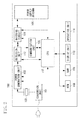
- a horizontal axis and a vertical axis illustrated in Fig. 7 represent time and power output from the power supply apparatus 100, respectively.
- the power supply apparatus 100 performs operations of authentication 701, communication 702, and a first power output 703. If the power reception status information 403 is not updated (NO in step S508), the power supply apparatus 100 also performs the operations of the authentication 701, the communication 702, and the first power output 703.
- the authentication 701 is the authentication operation for wirelessly communicating with the communication unit 204.
- the communication 702 is the operation for acquiring the power reception status information 403 from the electronic apparatus 200.
- the first power output 703 is the operation of outputting the first power.
- the power supply apparatus 100 After outputting the first power by the operation of the first power output 703, the power supply apparatus 100 performs operations of authentication 704 and communication 705.
- the authentication 704 is a similar operation to the authentication 701
- the communication 705 is a similar operation to the communication 702. If it is determined that the power reception status information 403 is updated (YES in step S508) after the power reception status information 403 is acquired from the electronic apparatus 200 by the operation of the communication 705 (YES in step S507), the power supply apparatus 100 performs an operation of a second power output 706.
- the second power output 706 is the operation of outputting the second power with use of the power reception status information 403 acquired from the electronic apparatus 200 by the operation of the communication 705.
- the power supply apparatus 100 After performing the operation of the second power output 706, the power supply apparatus 100 performs an operation of communication 707 again.
- the communication 707 is a similar operation to the communication 702.
- the power supply apparatus 100 After performing the operation of the communication 707, the power supply apparatus 100 performs an operation of a second power output 708.
- the second power output 708 is a similar operation to the second power output 706. After that, the power supply apparatus 100 repeatedly performs the operations of the communication 707 and the second power output 708 until determining not to supply the power to the electronic apparatus 200 (NO in step S509).
- the power supply apparatus 100 is configured to be able to determine whether the power reception status information 403 received from the electronic apparatus 200 is updated by the electronic apparatus 200. Furthermore, the power supply apparatus 100 is configured to determine whether the power reception status information 403 received from the electronic apparatus 200 is correct according to the result of the determination about whether the power reception status information 403 received from the electronic apparatus 200 is updated by the electronic apparatus 200.
- the power supply apparatus 100 can appropriately control, with use of the power reception status information 403 determined to be correct, power to be supplied wirelessly from the power supply apparatus 100 to the electronic apparatus 200. Furthermore, if the power reception status information 403 received from the electronic apparatus 200 is not updated by the electronic apparatus 200 (NO in step S508), the power supply apparatus 100 is configured to refrain from using the power reception status information 403 determined to be incorrect. As a result, the power supply apparatus 100 can be prevented from performing incorrect control on the electronic apparatus 200.
- the power supply apparatus 100 is configured to supply the power slight but enough to update the power reception status information 403 to the electronic apparatus 200.
- the power supply apparatus 100 can allow the electronic apparatus 200 to charge the battery 209 while preventing power from being excessively supplied to the electronic apparatus 200.
- the power supply apparatus 100 can bring the electronic apparatus 200 into the state capable of updating the power reception status information 403, and thus the power supply apparatus 100 can appropriately control, with use of the power reception status information 403 updated by the electronic apparatus 200, power to be supplied wirelessly from the power supply apparatus 100 to the electronic apparatus 200.
- the power supply apparatus 100 and the electronic apparatus 200 are assumed to wirelessly communicate with each other based on the NFC standard.
- the power supply apparatus 100 and the electronic apparatus 200 may wirelessly communicate with each other based on a standard other than the NFC standard.
- the power supply apparatus 100 and the electronic apparatus 200 may perform wireless communication in compliance with ISO/IEC (International Organization for Standardization/International Electrotechnical Commission) 18092 standard, instead of the NFC standard.
- the power supply apparatus 100 and the electronic apparatus 200 may perform wireless communication in compliance with Radio Frequency Identification (RFID), instead of the NFC standard.
- RFID Radio Frequency Identification
- the power supply apparatus 100 and the electronic apparatus 200 may perform wireless communication in compliance with ISO/IEC 14443 standard, instead of the NFC standard.
- the power supply apparatus 100 and the electronic apparatus 200 may perform wireless communication in compliance with TransferJet (registered trademark) standard, instead of the NFC standard.
- the power supply apparatus 100 and the electronic apparatus 200 may perform wireless communication in compliance with ISO/IEC 21481 standard, instead of the NFC standard.
- the power supply apparatus 100 and the electronic apparatus 200 may perform wireless communication in compliance with Bluetooth (registered trademark) standard or wireless LAN (local area network) standard, instead of the NFC standard.
- the power supply apparatus 100 is configured to supply the second power to the electronic apparatus 200 with use of the power supply antenna 106, and perform the communication between the communication unit 105 and the electronic apparatus 200 with use of the power supply antenna 106.
- the use of the antenna is not limited thereto.
- the power supply apparatus 100 may be configured to separately include an antenna for supplying the second power to the electronic apparatus 200, and an antenna for performing the communication between the communication unit 105 and the electronic apparatus 200. Therefore, a resonance frequency corresponding to the antenna for supplying the second power to the electronic apparatus 200, and a resonance frequency corresponding to the antenna for performing the communication between the communication unit 105 and the electronic apparatus 200 may be equal frequencies, or may be different frequencies.
- the resonance frequency corresponding to the antenna for supplying the second power to the electronic apparatus 200 may be 6.78 MHz, or may be a frequency of 100 KHz to 250 KHz.
- the resonance frequency corresponding to the antenna for performing the communication between the communication unit 105 and the electronic apparatus 200 may be a frequency other than 13.56 MHz as long as this frequency is a frequency in compliance with the communication standard of the communication unit 105.
- the electronic apparatus 200 is configured to receive power from the power supply apparatus 100 with use of the power reception antenna 201, and perform the communication between the power supply apparatus 100 and the communication unit 204 with use of the power reception antenna 201.
- the use of the antenna is not limited thereto.
- the electronic apparatus 200 may be configured to separately include an antenna for receiving power from the power supply apparatus 100, and an antenna for performing the communication between the power supply apparatus 100 and the communication unit 204. Therefore, a resonance frequency corresponding to the antenna for receiving power from the power supply apparatus 100, and a resonance frequency corresponding to the antenna for performing the communication between the power supply apparatus 100 and the communication unit 204 may be equal frequencies, or may be different frequencies.
- the resonance frequency corresponding to the antenna for receiving power from the power supply apparatus 100 may be 6.78 MHz, or may be a frequency of 100 KHz to 250 KHz.
- the resonance frequency corresponding to the antenna for performing the communication between the power supply apparatus 100 and the communication unit 204 may be a frequency other than 13.56 MHz as long as this frequency is a frequency corresponding to the communication standard of the communication unit 204.
- the power supply apparatus according to the present invention is not limited to the power supply apparatus 100 described in the first exemplary embodiment.
- the electronic apparatus according to the present invention is not also limited to the electronic apparatus 200 described in the first exemplary embodiment.
- each of the power supply apparatus and the electronic apparatus according to the present invention can be also realized by a system including apparatuses.
- various kinds of processes and functions described in the first exemplary embodiment can be also realized by a computer program.
- the computer program according to the present invention can be executed by a computer (including a CPU and the like), and is configured to realize various kinds of functions described in the first exemplary embodiment.
- the computer program according to the present invention may realize various kinds of processes and functions described in the first exemplary embodiment with use of an operating system (OS) and/or the like running on the computer.
- OS operating system
- the computer program according to the present invention is read out from a computer-readable recording medium to be executed by the computer.
- a hard disk device, an optical disk, a compact disk read only memory (CD-ROM), a compact disk recordable (CD-R), a memory card, a ROM, or the like can be used as the computer-readable recording medium.
- These recording media are non-transitory recording media.
- the computer program according to the present invention may be configured to be provided from an external apparatus to the computer via a communication interface to be executed by this computer.
Landscapes
- Engineering & Computer Science (AREA)
- Computer Networks & Wireless Communication (AREA)
- Power Engineering (AREA)
- Signal Processing (AREA)
- Charge And Discharge Circuits For Batteries Or The Like (AREA)
Abstract
Description
- The present invention relates to a power supply apparatus that wirelessly supplies power.
- In recent years, there has been known a power supply system that wirelessly transmits power without a connection using a connector. There has been known, in this type of power supply system, a power supply apparatus that performs data communication for transmitting a command to an electronic apparatus and transmitting power to the electronic apparatus via a same antenna (see Japanese Patent Application Laid-Open No.
2008-113519 - In this type of power supply system, there is a demand for allowing the power supply apparatus to control, with use of a state of the electronic apparatus, power to be supplied from the power supply apparatus to the electronic apparatus. In this case, the electronic apparatus needs to periodically detect its own state, and notify the power supply apparatus of a result of this detection.
- However, without supplying power required to detect a state of the electronic apparatus to the electronic apparatus, the electronic apparatus cannot detect its own state, and therefore cannot correctly notify the power supply apparatus of its own state. Therefore, in some cases, the power supply apparatus supplies excessive power to the electronic apparatus even though the power supply apparatus has controlled, with use of the state of the electronic apparatus notified from the electronic apparatus, power to be supplied from the power supply apparatus to the electronic apparatus.
- According to an aspect of the present invention, there is provided a power supply apparatus capable of appropriately controlling power to be supplied from the power supply apparatus to an electronic apparatus.
- According to an aspect of the present invention, there is provided a power supply apparatus capable of appropriately detecting a state of an electronic apparatus in a case where power is supplied from the power supply apparatus to the electronic apparatus.
- According to an aspect of the present invention, there is provided a power supply apparatus as specified in any one of
claims 1 to 10. - Further features and aspects of the present invention will become apparent from the following description of exemplary embodiments.
- The drawings, which are incorporated in and constitute a part of the specification, illustrate exemplary embodiments, features, and aspects of the present invention.
-
Fig. 1 illustrates an example of a power supply system according to a first exemplary embodiment. -
Fig. 2 is a block diagram illustrating an example of a power supply apparatus according to the first exemplary embodiment. -
Fig. 3 is a block diagram illustrating an example of an electronic apparatus according to the first exemplary embodiment. -
Fig. 4 illustrates an example of wireless power supply data group according to the first exemplary embodiment. -
Fig. 5 (consisting ofFigs. 5A and5B ) is a flowchart illustrating an example of a power supply process according to the first exemplary embodiment. -
Fig. 6 (consisting ofFigs. 6A and6B ) is a flowchart illustrating an example of a power reception process according to the first exemplary embodiment. -
Fig. 7 illustrates an example of an operation of the power supply apparatus according to the first exemplary embodiment. - Exemplary embodiments, features, and aspects of the present invention will be described below with reference to the drawings.
- In the following description, a first exemplary embodiment will be described in detail with reference to the drawings. As illustrated in
Fig. 1 , a power supply system according to the first exemplary embodiment includes apower supply apparatus 100 and anelectronic apparatus 200. In the power supply system according to the first exemplary embodiment, thepower supply apparatus 100 wirelessly supplies power to theelectronic apparatus 200 if theelectronic apparatus 200 is located within a predetermined range. Furthermore, theelectronic apparatus 200 wirelessly receives power output from thepower supply apparatus 100 if located within the predetermined range. On the other hand, theelectronic apparatus 200 cannot receive power from thepower supply apparatus 100 if not located within the predetermined range. The predetermined range is defined to be a range that allows thepower supply apparatus 100 and theelectronic apparatus 200 to communicate with each other. Furthermore, thepower supply apparatus 100 may wirelessly supply power to electronic apparatuses. - The
electronic apparatus 200 may be an image capture apparatus, such as a camera, or may be a reproduction apparatus that reproduces audio data and image data. Alternatively, theelectronic apparatus 200 may be a communication apparatus, such as a mobile phone and a smartphone. Alternatively, theelectronic apparatus 200 may be a battery pack including a battery 209. Alternatively, theelectronic apparatus 200 may be an apparatus such as a vehicle that is driven by power supplied from thepower supply apparatus 100. Alternatively, theelectronic apparatus 200 may be an apparatus that receives a television broadcast, a display that displays image data, or a personal computer. Furthermore, theelectronic apparatus 200 may be an apparatus that operates with use of power supplied from thepower supply apparatus 100 even without the battery 209 mounted thereon. -
Fig. 2 is a block diagram illustrating an example of a configuration of thepower supply apparatus 100. As illustrated inFig. 2 , thepower supply apparatus 100 includes aconversion unit 101, anoscillator 102, apower generation unit 103, amatching circuit 104, acommunication unit 105, apower supply antenna 106, a central processing unit (CPU) 107, a read only memory (ROM) 108, a random access memory (RAM) 109, adisplay unit 110, anoperation unit 111, and adetection unit 112. - In a case where an alternating-current (AC) power source and the
power supply apparatus 100 are connected to each other, theconversion unit 101 converts alternating-current power supplied from the AC power source into direct-current power, and supplies the converted direct-current power to thepower supply apparatus 100. - The
oscillator 102 produces a frequency signal that is used to control thepower generation unit 103 so as to convert power supplied from theconversion unit 101 into target power set by theCPU 107. A crystal oscillator or the like is used as theoscillator 102. - The
power generation unit 103 generates power to be output to the outside via thepower supply antennal 106 based on power supplied from theconversion unit 101 and the frequency signal produced by theoscillator 102. The power generated by thepower generation unit 103 is supplied to thematching circuit 104 via thedetection unit 112. - The power generated by the
power generation unit 103 includes first power and second power. The first power is power that is used for thecommunication unit 105 to communicate with theelectronic apparatus 200 via thepower supply antenna 106. The second power is power that is used for theelectronic apparatus 200 to charge the battery 209 and perform a predetermined process. For example, the first power is power of 1 W or lower, and the second power is power of 2 W or higher. The first power is defined to be power lower than the second power. Furthermore, the first power may be power specified in a communication standard of thecommunication unit 105. Furthermore, the first power is not limited to the power of 1 W or lower. Furthermore, the second power is not limited to the power of 2 W or higher as long as the second power is power usable to allow theelectronic apparatus 200 to charge thebattery 109 and perform the predetermined process. - The matching
circuit 104 is a resonance circuit for achieving resonance between thepower supply antenna 106 and apower reception antenna 201 of theelectronic apparatus 200. Furthermore, thematching circuit 104 includes a circuit for achieving impedance matching between thepower generation unit 103 and thepower supply antennal 106. Thematching circuit 104 includes an inductor and a capacitor. - In a case where the
power supply apparatus 100 outputs any one of the first power and the second power, theCPU 107 controls thematching circuit 104 so as to set a resonance frequency f of thepower supply antenna 106 to a predetermined frequency to achieve the resonance between thepower supply antenna 106 and thepower reception antenna 201. At this time, theCPU 107 changes the resonance frequency f of thepower supply antenna 106 by controlling a value of an inductance included in thematching circuit 104 and a value of the capacitor included in thematching circuit 104. Assume that the predetermined frequency is, for example, a frequency of 13.56 MHz. - The
communication unit 105 performs, for example, close proximity wireless communication based on NFC (Near Filed Communication) standard defined by the NFC forum. In a case where the first power is output from thepower supply antenna 106, thecommunication unit 105 can transmit and receive data for carrying out the wireless power supply with theelectronic apparatus 200 via thepower supply antenna 106. However, assume that thecommunication unit 105 does not communicate with theelectronic apparatus 200 via thepower supply antenna 106 while the second power is output from thepower supply antenna 106. In a case where the first power is output from thepower supply antenna 106, thecommunication unit 105 transmits the data to theelectronic apparatus 200 by superposing data onto the first power. In a case where transmitting the data to thepower supply apparatus 100, theelectronic apparatus 200 modulates a load inside theelectronic apparatus 200, which causes a change in a current flowing in thepower supply antenna 106. Therefore, thecommunication unit 105 can receive the data from theelectronic apparatus 200 by detecting the current flowing in thepower supply antenna 106, and analyzing that. - The data transmitted between the
communication unit 105 and theelectronic apparatus 200 is data in compliance with NFC Data Exchange Format (NDEF). - The
power supply antenna 106 is an antenna for outputting power generated by thepower generation unit 103 to the outside. Thepower supply apparatus 100 supplies power to theelectronic apparatus 200 via thepower supply antenna 106, and transmits the data to theelectronic apparatus 200 via thepower supply antenna 106. Furthermore, thepower supply apparatus 100 receives the data from theelectronic apparatus 200 via thepower supply antenna 106. - The
CPU 107 controls thepower supply apparatus 100 by executing a computer program stored in theROM 108. TheCPU 107 controls power to be supplied to theelectronic apparatus 200 by controlling thepower generation unit 103. - The
ROM 108 stores information such as the computer program for controlling thepower supply apparatus 100, and a parameter regarding thepower supply apparatus 100. - The
RAM 109 records the data acquired from theelectronic apparatus 200 by thecommunication unit 105. - The
display unit 110 displays image data provided from any one of theRAM 109 and theROM 108. Furthermore, thedisplay unit 110 displays a warning toward a user. Thedisplay unit 110 includes a light-emitting diode (LED) 113 including a light-emitting diode or the like. TheCPU 107 lights the LED 113 according to an operation performed by thepower supply apparatus 100. - The
operation unit 111 provides a user interface for operating thepower supply apparatus 100. Theoperation unit 111 includes a power button of thepower supply apparatus 100, a mode switching button of thepower supply apparatus 100, and the like. Each of the buttons is constituted by a switch, a touch panel, or the like. TheCPU 107 controls thepower supply apparatus 100 according to an input signal input via theoperation unit 111. - The
detection unit 112 detects a voltage standing wave ratio (VSWR) to detect a resonance state between thepower supply apparatus 100 and theelectronic apparatus 200. Furthermore, thedetection unit 112 provides data indicating the detected VSWR to theCPU 107. The VSWR is a value indicating a relationship between a traveling wave of power output from thepower supply antenna 106 and a reflection wave of power output from thepower supply antenna 106. TheCPU 107 can detect whether an object is placed in the vicinity of thepower supply apparatus 100 with use of the data indicating the VSWR that is provided from thedetection unit 112. - Next, an example of a configuration of the
electronic apparatus 200 will be described with reference toFig. 3 . Theelectronic apparatus 200 includes thepower reception antenna 201, amatching circuit 202, a rectification and smoothingcircuit 203, acommunication unit 204, aregulator 205, aCPU 206, and amemory 207. Furthermore, theelectronic apparatus 200 includes acharging unit 208, the battery 209, asystem 210, anoperation unit 213, and atimer 214. - The
power reception antenna 201 is an antenna for receiving power supplied from thepower supply apparatus 100. Theelectronic apparatus 200 receives power from thepower supply apparatus 100 via thepower reception antenna 201. Furthermore, theelectronic apparatus 200 wirelessly communicates with thepower supply apparatus 100 via thepower reception antenna 201. - The
matching circuit 202 is a resonance circuit for achieving the resonance between thepower supply antenna 106 and thepower reception antenna 201 according to a frequency equal to the resonance frequency f of thepower supply antenna 106. Furthermore, thematching circuit 202 includes a circuit for achieving impedance matching between thepower reception antenna 201 and the rectification and smoothingcircuit 203. Thematching circuit 202 includes an inductor and a capacitor. TheCPU 206 controls a value of the inductor and a value of the capacitor included in thematching circuit 202 so as to cause thepower reception antenna 201 to oscillate with the frequency equal to the resonance frequency f of thepower supply antenna 106. Furthermore, thematching circuit 202 supplies power received by thepower reception antenna 201 to the rectification and smoothingcircuit 203. - The rectification and smoothing
circuit 203 removes the data and a noise from power supplied from thematching circuit 202, and generates direct-current power. Furthermore, the rectification and smoothingcircuit 203 supplies the generated direct-current power to theregulator 205. The rectification and smoothingcircuit 203 provides the data removed from power received by thepower reception antenna 201 to thecommunication unit 204. - The
communication unit 204 wirelessly communicates with an external apparatus, such as thepower supply apparatus 100, according to the same communication standard as thecommunication unit 105. Thecommunication unit 204 analyzes the data provided from the rectification and smoothingcircuit 203, and provides a result of the analysis of the data to theCPU 206. In a case where the first power is supplied from thepower supply apparatus 100 to theelectronic apparatus 200, theCPU 206 transmits response data as a response to the received data to thepower supply apparatus 100. At this time, theCPU 206 controls thecommunication unit 204 so as to change a load included in thecommunication unit 204 to transmit the response data as the response to the received data to thepower supply apparatus 100. Thecommunication unit 204 includes amemory 204a. - The
memory 204a stores a wireless powersupply data group 400.Fig. 4 illustrates the wireless powersupply data group 400. The wireless powersupply data group 400 stores the data transmitted between thepower supply apparatus 100 and theelectronic apparatus 200. The wireless powersupply data group 400stores device information 401, powersupply status information 402, and powerreception status information 403. Thedevice information 401, the powersupply status information 402, and the powerreception status information 403 are data in compliance with NDEF. - The
device information 401 includes information for identifying theelectronic apparatus 200, information for identifying a power supply method that theelectronic apparatus 200 supports, information indicating a power class of theelectronic apparatus 200, and the like. Furthermore, thedevice information 401 includes information indicating the number of power supply methods that theelectronic apparatus 200 supports. Therefore, in a case where theelectronic apparatus 200 supports power supply methods, thedevice information 401 includes information indicating that theelectronic apparatus 200 supports the plurality of power supply methods. Furthermore, thedevice information 401 includes information indicating a response time, which is a time taken since the powerreception status information 403 is requested from thepower supply apparatus 100 until theelectronic apparatus 200 transmits the powerreception status information 403 to thepower supply apparatus 100. The information indicating the power class of theelectronic apparatus 200 is information indicating a maximum value of the power that theelectronic apparatus 200 can receive from thepower supply apparatus 100. For example, in a case where the maximum value of the power that theelectronic apparatus 200 can receive from thepower supply apparatus 100 is 1 W, information indicating that theelectronic apparatus 200 supports a low power class is set as the information indicating the power class of theelectronic apparatus 200. For example, in a case where the maximum value of the power that theelectronic apparatus 200 can receive from thepower supply apparatus 100 is 3 W, information indicating that theelectronic apparatus 200 supports a middle power class is set as the information indicating the power class of theelectronic apparatus 200. For example, in a case where the maximum value of the power that theelectronic apparatus 200 can receive from thepower supply apparatus 100 is 6 W, information indicating that theelectronic apparatus 200 supports a high power class is set as the information indicating the power class of theelectronic apparatus 200. - The
device information 401 is information transmitted to thepower supply apparatus 100 by thecommunication unit 204. Thedevice information 401 is fixed data stored in thememory 204a in advance. - The power
supply status information 402 includes information indicating whether thepower supply apparatus 100 starts or stops supplying power from thepower supply apparatus 100 to theelectronic apparatus 200, information indicating whether an error occurs in thepower supply apparatus 100, and update data, which will be described below. The powersupply status information 402 may further include information indicating a time period during which the second power is output. Furthermore, the powersupply status information 402 includes information for identifying a power supply method that thepower supply apparatus 100 supports, and information indicating the number of power supply methods that thepower supply apparatus 100 supports. Furthermore, the powersupply status information 402 includes information indicating a power class of thepower supply apparatus 100. The information indicating the power class of thepower supply apparatus 100 is information indicating a maximum value of the power that thepower supply apparatus 100 can output. For example, in a case where the maximum value of the power that thepower supply apparatus 100 can output is 3 W, information indicating that thepower supply apparatus 100 supports a low power class is set as the information indicating the power class of thepower supply apparatus 100. For example, in a case where the maximum value of the power that thepower supply apparatus 100 can output is 10 W, information indicating that thepower supply apparatus 100 supports a middle power class is set as the information indicating the power class of thepower supply apparatus 100. For example, in a case where the maximum value of the power that thepower supply apparatus 100 can output is 20 W, information indicating that thepower supply apparatus 100 supports a high power class is set as the information indicating the power class of thepower supply apparatus 100. - The power
supply status information 402 is information stored into the wireless powersupply data group 400 in thememory 204a from thecommunication unit 105. After the powersupply status information 402 is stored into thememory 204a, theCPU 206 can control theelectronic apparatus 200 according to the powersupply status information 402 by reading out the powersupply status information 402. - The power
reception status information 403 includes information indicating whether an error occurs in theelectronic apparatus 200, information indicating whether theelectronic apparatus 200 requests thepower supply apparatus 100 to supply power, and update data, which will be described below. The powerreception status information 403 may further include any one of information for requesting thepower supply apparatus 100 to increase power supplied to theelectronic apparatus 200, and information for requesting thepower supply apparatus 100 to reduce power supplied to theelectronic apparatus 200. The powerreception status information 403 may further include information for requesting thepower supply apparatus 100 to keep power supplied to theelectronic apparatus 200 at a present level. Furthermore, the powerreception status information 403 may further include information regarding a remaining capacity of the battery 209 and/or information regarding the charging of the battery 209. The powerreception status information 403 is information stored into the wireless powersupply data group 400 in thememory 204a by theCPU 206. The powerreception status information 403 is periodically updated by theCPU 206. - The
communication unit 204 consumes power lower than theCPU 206. Thecommunication unit 204 can communicate with thecommunication unit 105 with use of power received from thepower supply apparatus 100 by thepower reception antenna 201 while the first power is output from thepower supply apparatus 100. - The
regulator 205 performs control so as to supply power supplied from any one of the rectification and smoothingcircuit 203 and the battery 209 to theelectronic apparatus 200. Theregulator 205 supplies power supplied from thepower supply apparatus 100 via the rectification and smoothingcircuit 203 to theelectronic apparatus 200 according to an instruction from theCPU 206. Theregulator 205 supplies discharged power supplied from the battery 209 via thecharging unit 208 to theelectronic apparatus 200 according to an instruction from theCPU 206. - The
CPU 206 controls theelectronic apparatus 200 according to the result of the analysis of the data provided from thecommunication unit 204. Furthermore, theCPU 206 controls theelectronic apparatus 200 by executing a computer program stored in thememory 207. - The
CPU 206 generates the powerreception status information 403 according to information provided from each of the units of theelectronic apparatus 200, deletes the powerreception status information 403 stored in thememory 204a, and then stores the newly generated powerreception status information 403 into the wireless powersupply data group 400. With this operation, theCPU 206 periodically updates the powerreception status information 403. - The
memory 207 stores the computer program for controlling theelectronic apparatus 200. Furthermore, thememory 207 records information regarding theelectronic apparatus 200, and the like. - The charging
unit 208 charges the battery 209 with use of power supplied from theregulator 205. Furthermore, in a case where power is not supplied from theregulator 205, the chargingunit 208 supplies the discharged power supplied from the battery 209 to theregulator 205. The chargingunit 208 periodically detects the information regarding the battery 209 and the information regarding the charging of the battery 209, and notifies theCPU 206 of the detected information. - The battery 209 is a battery attachable to and detachable from the
electronic apparatus 200. Furthermore, the battery 209 is a chargeable secondary battery. - The
system 210 includes arecording unit 211 and animage capture unit 212. - The
recording unit 211 records data such as image data and audio data provided from theimage capture unit 212 into arecording medium 211a. Furthermore, therecording unit 211 reads out the data such as the image data and the audio data from therecording medium 211a. Therecording medium 211a may be a hard disk, a memory card, or the like, and may be built in theelectronic apparatus 200 or may be an external recording medium detachably attached to theelectronic apparatus 200. - The
image capture unit 212 includes an image sensor for generating image data from an optical image of an object, an image processing circuit that performs image processing on the image data generated by the image sensor, a compression and decompression circuit for compressing the image data and decompressing the compressed image data, and the like. Theimage capture unit 212 captures an image of an object, and provides the image data, such as a still image or a moving image, acquired from a result of the image capturing to therecording unit 211. Therecording unit 211 records the image data provided from theimage capture unit 212 into therecording medium 211a. Theimage capture unit 212 may further include a configuration required to capture an image of an object. - The
system 210 includes a unit to which power is supplied from theregulator 205 while theelectronic apparatus 200 is powered on. Therefore, thesystem 210 may further include a display unit for displaying the image data, a unit for transmitting and receiving an electronic mail, in addition to therecording unit 211, therecording medium 211a, and theimage capture unit 212. - The
operation unit 213 is a user interface for operating theelectronic apparatus 200. Theoperation unit 213 includes a power button for operating theelectronic apparatus 200, a mode switching button for switching a mode of theelectronic apparatus 200. Each of the buttons is constituted by a switch, a touch panel, or the like. In a case where being operated by the user, theoperation unit 213 provides a signal corresponding to the operation performed by the user to theCPU 206. Theoperation unit 213 may control theelectronic apparatus 200 according to a remote signal received from a remote controller. - The
timer 214 measures a time regarding a process performed by each of the units of theelectronic apparatus 200. - Furthermore, each of the
power supply antenna 106 and thepower reception antenna 201 may be a helical antenna or a loop antenna, or may be a planar antenna, such as a meander line antenna. - In the first exemplary embodiment, the
power supply apparatus 100 is configured to wirelessly supply power to theelectronic apparatus 200 based on the magnetic resonance method, but the method for wirelessly supplying power is not limited thereto. - For example, the
power supply apparatus 100 may be configured to wirelessly supply power to theelectronic apparatus 200 based on electric field coupling, instead of the magnetic resonance method. In this case, an electrode is required to be mounted on each of thepower supply apparatus 100 and theelectronic apparatus 200, and power is wirelessly supplied from the electrode of thepower supply apparatus 100 to the electrode of theelectronic apparatus 200. - Alternatively, for example, the
power supply apparatus 100 may be configured to wirelessly supply power to theelectronic apparatus 200 based on electromagnetic induction, instead of the magnetic resonance method. - The
power supply apparatus 100 is configured to wirelessly supply power to theelectronic apparatus 200. However, the term "wirelessly" may be replaced with a phrase "in a non-contact manner" or a phrase "in a contactless manner". - Next, a power supply process performed by the
CPU 107 according to the first exemplary embodiment will be described with reference to a flowchart illustrated inFig. 5 (consisting ofFigs. 5A and5B ). TheCPU 107 executes the computer program stored in theROM 108, by which the power supply process can be realized. - In a case where the
power supply apparatus 100 is powered on, in step S501, theCPU 107 controls at least one of theoscillator 102, thepower generation unit 103, and thematching circuit 104 so as to output the first power via thepower supply antenna 106. Then, the power supply process proceeds to step S502. - In step S502, the
CPU 107 causes thecommunication unit 105 to carry out authentication for wirelessly communicating with thecommunication unit 204. Then, the power supply process proceeds to step S503. - In step S503, the
CPU 107 determines whether the authentication for wirelessly communicating with thecommunication unit 204 is completed. If the authentication for wirelessly communicating with thecommunication unit 204 is completed (YES in step S503), the power supply process proceeds to step S504. If the authentication for wirelessly communicating with thecommunication unit 204 is not completed (NO in step S503), the power supply process proceeds to step S511. - In step S504, the
CPU 107 determines whether theelectronic apparatus 200 supports the wireless power supply. For example, theCPU 107 controls thecommunication unit 105 so as to transmit data for acquiring thedevice information 401 to theelectronic apparatus 200. In a case where thedevice information 401 is received by thecommunication unit 105, theCPU 107 determines whether theelectronic apparatus 200 supports the wireless power supply with use of thedevice information 401 received by thecommunication unit 105. If theelectronic apparatus 200 supports the wireless power supply (YES in step S504), the power supply process proceeds to step S505. If theelectronic apparatus 200 does not support the wireless power supply (NO in step S504), the power supply process proceeds to step S511. - In step S505, the
CPU 107 generates the powersupply status information 402, and controls thecommunication unit 105 so as to transmit the generated powersupply status information 402 to theelectronic apparatus 200. The powersupply status information 402 generated by theCPU 107 in step S505 includes information indicating that thepower supply apparatus 100 will start supplying power from thepower supply apparatus 100 to theelectronic apparatus 200, information indicating that no error occurs in thepower supply apparatus 100, and the update data. The update data is used to determine whether the powerreception status information 403 is updated by theCPU 206. The update data may be a randomly generated value, or may be a predetermined value. TheCPU 107 generates the powersupply status information 402 by reading out the update data stored in theRAM 109. The description will be given below, assuming that a value of the update data transmitted to theelectronic apparatus 200 in step S505 is set to "N". Assume that "N" is a natural number. - Upon the transmission of the power
supply status information 402 by thecommunication unit 105, the power supply process proceeds to step S506. The powersupply status information 402 transmitted by thecommunication unit 105 is stored into the wireless powersupply data group 400 in thememory 204a. - Upon receiving the power
supply status information 402, thecommunication unit 204 stores the powersupply status information 402 received from thepower supply apparatus 100 into the wireless powersupply data group 400 in thememory 204a. At this time, thecommunication unit 204 notifies theCPU 206 that the powersupply status information 402 is received. - In step S506, the
CPU 107 controls thecommunication unit 105 so as to transmit data for requesting the powerreception status information 403 to theelectronic apparatus 200. Then, the power supply process proceeds to step S507. - Upon receiving the data for requesting the power
reception status information 403, thecommunication unit 204 notifies theCPU 206 that the powerreception status information 403 is requested. Therefore, if sufficient power is supplied from any one of the battery 209 and the rectification and smoothingcircuit 203, and if no error occurs in theCPU 206, theCPU 206 performs a process for updating the powerreception status information 403 stored in thememory 204a. Upon completing the update of the powerreception status information 403 stored in thememory 204a, theCPU 206 reads out the powersupply status information 402 from the wireless powersupply data group 400 in thememory 204a, and acquires the update data included in the powersupply status information 402. After that, theCPU 206 adds a specific value to the value of the update data acquired from the powersupply status information 402, and stores the value of the update data with the specific value added thereto into the powerreception status information 403. For example, if the value of the update data included in the powersupply status information 402 is set to "N", theCPU 206 adds "1", which is the specific value, to the value "N" of the update data after completing the update of the powerreception status information 403. After that, theCPU 206 stores the value "N + 1" of the update data acquired as a result of the calculation into the powerreception status information 403. TheCPU 206 does not add the specific value to the update data acquired from the powersupply status information 402 until completing the update of the powerreception status information 403. Therefore, the same update data as the update data included in the powersupply status information 402 is stored in the powerreception status information 403 stored in thememory 204a until the completion of the update of the powerreception status information 403. - However, if the sufficient power is not supplied from the battery 209 and the rectification and smoothing
circuit 203, theCPU 206 cannot update the powerreception status information 403 stored in thememory 204a. In this case, since the powerreception status information 403 stored in thememory 204a is not updated, the same update data as the update data included in the powersupply status information 402 is stored in the powerreception status information 403 stored in thememory 204a. - Furthermore, even when the sufficient power is supplied from any one of the battery 209 and the rectification and smoothing
circuit 203, theCPU 206 cannot update the powerreception status information 403 stored in thememory 204a if an error occurs in theCPU 206. In this case, since the powerreception status information 403 stored in thememory 204a is not updated, the same value of the update data as the value of the update data included in the powersupply status information 402 is stored in the powerreception status information 403 stored in thememory 204a. - Upon receiving the data for requesting the power
reception status information 403 from thepower supply apparatus 100, thecommunication unit 204 transmits the powerreception status information 403 stored in the wireless powersupply data group 400 in thememory 204a to thepower supply apparatus 100 as the response data within the response time. Therefore, if the powerreception status information 403 is updated by theCPU 206, thecommunication unit 204 transmits the updated powerreception status information 403 to thepower supply apparatus 100 as the response data. On the other hand, if the powerreception status information 403 is not updated by theCPU 206, thecommunication unit 204 transmits the non-updated powerreception status information 403 to thepower supply apparatus 100 as the response data. - In step S507, the
CPU 107 determines whether the powerreception status information 403 is received from theelectronic apparatus 200 by thecommunication unit 105 during a time period since the data for requesting the powerreception status information 403 has been transmitted until the response time has elapsed. The response time in step S507 is the time indicated in thedevice information 401. If the powerreception status information 403 is received from theelectronic apparatus 200 by thecommunication unit 105 by the elapse of the response time (YES in step S507), the power supply process proceeds to step S508. If the powerreception status information 403 is not received from theelectronic apparatus 200 by thecommunication unit 105 even after the response time has elapsed (NO in step S507), the power supply process proceeds to step S513. - In step S508, the
CPU 107 determines whether the powerreception status information 403 is updated by theelectronic apparatus 200. - For example, the
CPU 107 analyzes the powerreception status information 403 received from theelectronic apparatus 200 by thecommunication unit 105, and acquires the update data included in the powerreception status information 403. After that, theCPU 107 determines whether the powerreception status information 403 is updated by theelectronic apparatus 200 with use of the update data included in the powerreception status information 403. At this time, theCPU 107 determines whether the update data stored in theRAM 109 before the reception of the powerreception status information 403 in step S507 matches the update data included in the powerreception status information 403 received in step S507. If the update data stored in theRAM 109 matches the update data included in the powerreception status information 403 received from theelectronic apparatus 200, theCPU 107 determines that the powerreception status information 403 is not updated by the electronic apparatus 200 (NO in step S508). On the other hand, if the update data stored in theRAM 109 does not match the update data included in the powerreception status information 403 received from theelectronic apparatus 200, theCPU 107 determines that the powerreception status information 403 is updated by the electronic apparatus 200 (YES in step S508). For example, if the update data stored in theRAM 109 is set to "N", theCPU 107 determines that the powerreception status information 403 is not updated by the electronic apparatus 200 (NO in step S508) if the update data received from theelectronic apparatus 200 is set to "N". On the other hand, if the update data stored in theRAM 109 is set to "N", theCPU 107 determines that the powerreception status information 403 is updated by the electronic apparatus 200 (YES in step S508) if the update data received from theelectronic apparatus 200 is set to "N + 1". - If the power
reception status information 403 is updated by the electronic apparatus 200 (YES in step S508), theCPU 107 determines that the powerreception status information 403 acquired from theelectronic apparatus 200 in step S507 is correct information, and then the power supply process proceeds to step S509. If the powerreception status information 403 is not updated by the electronic apparatus 200 (NO in step S508), theCPU 107 determines that the powerreception status information 403 acquired from theelectronic apparatus 200 in step S507 is not correct information, and then the power supply process proceeds to step S513. In a case where theCPU 107 determines that the powerreception status information 403 acquired from theelectronic apparatus 200 is not correct information, theCPU 107 refrains from using the powerreception status information 403 acquired from theelectronic apparatus 200 to control power to be supplied wirelessly from thepower supply apparatus 100 to theelectronic apparatus 200. - If the power
reception status information 403 is updated by the electronic apparatus 200 (YES in step S508), theCPU 107 deletes the update data stored in theRAM 109, and stores the update data included in the powerreception status information 403 into theRAM 109. At this time, if the update data included in the powerreception status information 403 is set to "N + 1", theCPU 107 stores the value "N + 1" of the update data into theRAM 109. - In step S509, the
CPU 107 controls whether to supply power to theelectronic apparatus 200 with use of the powerreception status information 403 acquired from theelectronic apparatus 200. For example, if the powerreception status information 403 includes information indicating that theelectronic apparatus 200 does not request thepower supply apparatus 100 to supply power, theCPU 107 determines not to supply power to the electronic apparatus 200 (NO in step S509). If the powerreception status information 403 includes information indicating that the battery 209 is fully charged, theCPU 107 determines not to supply power to the electronic apparatus 200 (NO in step S509). If the powerreception status information 403 includes information indicating that an error occurs in theelectronic apparatus 200, theCPU 107 determines not to supply power to the electronic apparatus 200 (NO in step S509). If the powerreception status information 403 includes information indicating that theelectronic apparatus 200 requests thepower supply apparatus 100 to supply power, theCPU 107 determines to supply power to the electronic apparatus 200 (YES in step S509). If the powerreception status information 403 includes information indicating that the battery 209 is not fully charged, theCPU 107 determines to supply the power to the electronic apparatus 200 (YES in step S509). If the powerreception status information 403 includes information indicating that no error occurs in theelectronic apparatus 200, theCPU 107 determines to supply power to the electronic apparatus 200 (YES in step S509). - If the
CPU 107 determines to supply power to the electronic apparatus 200 (YES in step S509), the power supply process proceeds to step S510. If theCPU 107 determines not to supply power to the electronic apparatus 200 (NO in step S509), the power supply process proceeds to step S512. - In step S510, the
CPU 107 controls at least one of theoscillator 102, thepower generation unit 103, and thematching circuit 104 so as to supply the second power via thepower supply antenna 106. In step S510, theCPU 107 sets a magnitude of the second power to be output via thepower supply antenna 106 with use of at least one of thedevice information 401 and the powerreception status information 403. After the power supply period has elapsed since the start of the output of the second power, theCPU 107 controls at least one of theoscillator 102, thepower generation unit 103, and thematching circuit 104 so as to switch power to be output via thepower supply antenna 106 from the second power to the first power. After that, the power supply process returns to step S505. The power supply period is the time period during which thepower supply apparatus 100 outputs power that allows theelectronic apparatus 200 to charge the battery 209 to theelectronic apparatus 200. The power supply period may be a time period set by theCPU 107, or may be a predetermined time period. TheCPU 107 may be configured to set the power supply time with use of thedevice information 401 acquired from theelectronic apparatus 200. Upon the start of the output of the second power in step S510, theCPU 107 notifies the user that thepower supply apparatus 100 is supplying power to theelectronic apparatus 200 by lighting the LED 113. Furthermore or alternatively, upon the start of the output of the second power, theCPU 107 may notify the user that thepower supply apparatus 100 is supplying power to theelectronic apparatus 200 by controlling thedisplay unit 110. After the start of the output of the second power, the power supply process returns to step S505. - In a case where the process of step S505 is performed again after the process of step S510 is performed, the
CPU 107 generates the powersupply status information 402 including the value of the update data that has been stored into theRAM 109 in step S508. After that, theCPU 107 controls thecommunication unit 105 so as to transmit the generated powersupply status information 402 to theelectronic apparatus 200. - In step S511, the
CPU 107 controls at least one of theoscillator 102, thepower generation unit 103, and thematching circuit 104 so as to stop the output of the power via thepower supply antenna 106. Then, the power supply process ends. - In step S512, the
CPU 107 generates the powersupply status information 402, and controls thecommunication unit 105 so as to transmit the generated powersupply status information 402 to theelectronic apparatus 200. The powersupply status information 402 generated by theCPU 107 in step S512 includes information indicating that thepower supply apparatus 100 will stop supplying power from thepower supply apparatus 100 to theelectronic apparatus 200. If an error occurs in thepower supply apparatus 100, the powersupply status information 402 generated by theCPU 107 in step S512 further includes information indicating that an error occurs in thepower supply apparatus 100. - Upon the transmission of the power
supply status information 402 by thecommunication unit 105, the power supply process proceeds to step S511. In a case where the powersupply status information 402 is transmitted by thecommunication unit 105, theCPU 107 notifies the user that the power supply from thepower supply apparatus 100 to theelectronic apparatus 200 is completed by lighting the LED 113. Alternatively, in a case where the output of the first power is started, theCPU 107 may notify the user that the power supply from thepower supply apparatus 100 to theelectronic apparatus 200 is completed by controlling thedisplay unit 110. - If the sufficient power is not supplied from any one of the battery 209 and the rectification and smoothing
circuit 203 to theCPU 206, theCPU 206 may be unable to generate the powerreception status information 403. In this case, since the powerreception status information 403 is not stored in thememory 204a, theelectronic apparatus 200 may be unable to transmit the powerreception status information 403 to thepower supply apparatus 100, even when the powerreception status information 403 is requested from thepower supply apparatus 100. To solve such a situation, if the powerreception status information 403 is not received from the electronic apparatus 200 (NO in step S507), thepower supply apparatus 100 supplies power for charging the battery 209 to theelectronic apparatus 200 so that the remaining capacity of the battery 209 reaches or exceeds a predetermined value. The predetermined value corresponds to the remaining capacity when the battery 209 can supply, to theCPU 206, power required to allow theCPU 206 to generate the powerreception status information 403 and store the generated powerreception status information 403 into thememory 204a. If the remaining capacity of the battery 209 is the predetermined value or larger, theCPU 206 can generate the powerreception status information 403 and store the generated powerreception status information 403 into thememory 204a with use of power supplied from the battery 209. Therefore, theCPU 107 performs a process of step S513. - If the sufficient power is not supplied from any one of the battery 209 and the rectification and smoothing
circuit 203 to theCPU 206, theCPU 206 may be unable to update the powerreception status information 403 stored in thememory 204a. In this case, theelectronic apparatus 200 may transmit the non-updated powerreception status information 403 to thepower supply apparatus 100 according to the issue of the request for the powerreception status information 403 from thepower supply apparatus 100. To solve such a situation, if the powerreception status information 403 is not updated (NO in step S508), thepower supply apparatus 100 supplies power for charging the battery 209 to theelectronic apparatus 200 so that the remaining capacity of the battery 209 reaches or exceeds a predetermined value. If the remaining capacity of the battery 209 is the predetermined value or larger, theCPU 206 can update the powerreception status information 403 with use of power supplied from the battery 209. Therefore, theCPU 107 performs the process of step S513. - In step S513, the
CPU 107 controls at least one of theoscillator 102, thepower generation unit 103, and thematching circuit 104 so as to output the first power via thepower supply antenna 106 to allow theelectronic apparatus 200 to charge the battery 209. - In a case where the process of step S513 is performed, the
CPU 107 cannot check the state of theelectronic apparatus 200 and the state of the battery 209. Therefore, if thepower supply apparatus 100 supplies high power to theelectronic apparatus 200 as the power that allows theelectronic apparatus 200 to charge the battery 209, this may result in supply of excessive power to theelectronic apparatus 200. To prevent such a situation, in step S513, theCPU 107 controls at least one of theoscillator 102, thepower generation unit 103, and thematching circuit 104 to output the first power, which is expected not to be excessive power for theelectronic apparatus 200, to theelectronic apparatus 200. - After a predetermined time has elapsed since the start of the output of the first power, the power supply process proceeds to step S514. Upon the start of the output of the first power in step S513, the
CPU 107 notifies the user that thepower supply apparatus 100 is supplying the power to theelectronic apparatus 200 by lighting the LED 113. Alternatively, upon the start of the output of the first power, theCPU 107 may notify the user that thepower supply apparatus 100 is supplying the power to theelectronic apparatus 200 by controlling thedisplay unit 110. - In step S514, the
CPU 107 controls thecommunication unit 105 so as to temporarily disconnect the wireless communication with theelectronic apparatus 200. After that, theCPU 107 causes thecommunication unit 105 to carry out the authentication for wirelessly communicating with thecommunication unit 204 again. Then, the power supply process proceeds to step S515. - In step S515, the
CPU 107 determines whether the authentication for wirelessly communicating with thecommunication unit 204 is completed, similarly to step S503. If the authentication for wirelessly communicating with thecommunication unit 204 is completed (YES in step S515), the power supply process proceeds to step S516. If the authentication for wirelessly communicating with thecommunication unit 204 is not completed (NO in step S515), the power supply process proceeds to step S511. - In step S516, the
CPU 107 determines whether theelectronic apparatus 200 supports the wireless power supply, similarly to step S504. If theelectronic apparatus 200 supports the wireless power supply (YES in step S516), the power supply process returns to step S506. If theelectronic apparatus 200 does not support the wireless power supply (NO in step S516), the power supply process proceeds to step S511. - If the
electronic apparatus 200 supports the wireless power supply (YES in step S516), the power supply process returns to step S506. If the powerreception status information 403 is not received from the electronic apparatus 200 (NO in step S507), theCPU 206 has been unable to add the specific value to the value of the update data included in the powersupply status information 402. In this case, even if theCPU 107 performs the process of step S505 again, this process just results in transmission of the same data as the powersupply status information 402 previously transmitted to theelectronic apparatus 200 to theelectronic apparatus 200. Therefore, theCPU 107 prevents itself from repeating the transmission of the same data to facilitate a quick increase in the remaining capacity of the battery 209 to the predetermined value or larger. For this reason, if the powerreception status information 403 is not received from the electronic apparatus 200 (NO in step S507), theCPU 107 performs the process of step S506 without performing the process of step S505. - If the power
reception status information 403 is not updated by the electronic apparatus 200 (NO in step S508), theCPU 107 also performs the process of step S506 without performing the process of step S505 in a similar manner, thereby preventing itself from repeating the transmission of the same data. - The
CPU 107 is configured to determine, in step S508, whether the powerreception status information 403 is updated by theelectronic apparatus 200 according to whether the specific value is added by theelectronic apparatus 200 to the value of the update data transmitted from thepower supply apparatus 100. However, the method for determining the update is not limited thereto. For example, theCPU 206 may cause thecommunication unit 204 to transmit, to thepower supply apparatus 100, data generated by subtracting a specific value from the value of the update data received from thepower supply apparatus 100, after completing the update of the powerreception status information 403. In this case, theCPU 107 is configured to determine, in step S508, whether the powerreception status information 403 is updated by theelectronic apparatus 200 according to whether the specific value is subtracted by theelectronic apparatus 200 from the value of the update data transmitted from thepower supply apparatus 100. - Alternatively, for example, the
CPU 206 may cause thecommunication unit 204 to transmit, to thepower supply apparatus 100, data generated by changing the value of the update data received from thepower supply apparatus 100, after completing the update of the powerreception status information 403. In this case, theCPU 107 is configured to determine, in step S508, whether the powerreception status information 403 is updated by theelectronic apparatus 200 according to whether any change is made by theelectronic apparatus 200 to the value of the update data transmitted from thepower supply apparatus 100. - If the power
reception status information 403 is updated by the electronic apparatus 200 (YES in step S508), theCPU 107 may further determine that the remaining capacity of the battery 209 is the predetermined value or larger. If the powerreception status information 403 is not updated by the electronic apparatus 200 (NO in step S508), theCPU 107 may further determine that the remaining capacity of the battery 209 is not the predetermined value or larger. - The
CPU 107 is configured to control, in step S513, at least one of theoscillator 102, thepower generation unit 103, and thematching circuit 104 so as to output the first power to theelectronic apparatus 200. However, the power expected not to be excessive power for theelectronic apparatus 200 is not limited to the first power. Therefore, theCPU 107 may be configured to cause, in step S513, power other than the first power to be output to theelectronic apparatus 200 as long as theCPU 107 causes the power expected not to be excessive power for theelectronic apparatus 200 to be output to theelectronic apparatus 200. - If the wireless communication between the
electronic apparatus 200 and thecommunication unit 105 is disconnected, theCPU 107 resets the update data stored in theRAM 109. After that, in a case where acquiring the powerreception status information 403 after the wireless communication between theelectronic apparatus 200 and thecommunication unit 105 is established, theCPU 107 sets the update data again, and performs control so as to transmit the powersupply status information 402 including this update data to theelectronic apparatus 200. - Alternatively, the
CPU 107 may reset the update data stored in theRAM 109 after the wireless communication between theelectronic apparatus 200 and thecommunication unit 105 is disconnected and then the wireless communication between theelectronic apparatus 200 and thecommunication unit 105 is established. In this case, when acquiring the powerreception status information 403, theCPU 107 sets the update data again, and performs control so as to transmit the powersupply status information 402 including this update data to theelectronic apparatus 200. - A power reception process performed by the
electronic apparatus 200 will be described with reference to a flowchart illustrated inFig. 6 (consisting ofFigs. 6A and6B ). - In a case where the
power reception antenna 201 receives power from thepower supply apparatus 100, and power received by thepower reception antenna 201 is supplied to thecommunication unit 204, in step S601, thecommunication unit 204 carries out the authentication for wirelessly communicating with thecommunication unit 105. After that, the power reception process proceeds to step S602. - In step S602, the
communication unit 204 determines whether the authentication for wirelessly communicating with thecommunication unit 105 is completed. If the authentication for wirelessly communicating with thecommunication unit 105 is completed (YES in step S602), the power reception process proceeds to step S603. If the authentication for wirelessly communicating with thecommunication unit 105 is not completed (NO in step S602), the power reception process ends. - In step S603, the
communication unit 204 determines whether data is received from thepower supply apparatus 100. If data is received from thepower supply apparatus 100 by the communication unit 204 (YES in step S603), the power reception process proceeds to step S604. If data is not received from thepower supply apparatus 100 by the communication unit 204 (NO in step S603), the power reception process returns to step S603. - In step S604, the
communication unit 204 determines whether the powersupply status information 402 including the information indicating that thepower supply apparatus 100 will stop supplying power from thepower supply apparatus 100 to theelectronic apparatus 200 is received. If the powersupply status information 402 including the information indicating that thepower supply apparatus 100 will stop supplying power from thepower supply apparatus 100 to theelectronic apparatus 200 is stored into the wireless powersupply data group 400 in thememory 204a (YES in step S604), thecommunication unit 204 transmits the response data to thepower supply apparatus 100. Then, the power reception process ends. If the powersupply status information 402 including the information indicating that thepower supply apparatus 100 will stop supplying power from thepower supply apparatus 100 to theelectronic apparatus 200 is not received (NO in step S604), the power reception process proceeds to step S605. - In step S605, the
communication unit 204 determines whether the data for requesting thedevice information 401 is received. If the data for requesting thedevice information 401 is received (YES in step S605), the power reception process proceeds to step S606. If the data for requesting thedevice information 401 is not received (NO in step S605), the power reception process proceeds to step S607. - In step S606, the
communication unit 204 transmits thedevice information 401 read out from the wireless powersupply data group 400 in thememory 204a to thepower supply apparatus 100. Then, the power reception process proceeds to step S614. - In step S607, the
communication unit 204 determines whether the powersupply status information 402 including the information indicating that thepower supply apparatus 100 will start supplying power from thepower supply apparatus 100 to theelectronic apparatus 200 is received. If the powersupply status information 402 including the information indicating that thepower supply apparatus 100 will start supplying power from thepower supply apparatus 100 to theelectronic apparatus 200 is stored into the wireless powersupply data group 400 in thememory 204a (YES in step S607), thecommunication unit 204 transmits the response data to thepower supply apparatus 100. Then, the power reception process proceeds to step S612. If the powersupply status information 402 including the information indicating that thepower supply apparatus 100 will start supplying power from thepower supply apparatus 100 to theelectronic apparatus 200 is not received (NO in step S607), the power reception process proceeds to step S608. - In step S608, the
communication unit 204 determines whether the data for requesting the powerreception status information 403 is received. If the data for requesting the powerreception status information 403 is received (YES in step S608), the power reception process proceeds to step S609. If the data for requesting the powerreception status information 403 is received (YES in step S608), thecommunication unit 204 outputs a notification to theCPU 206 to instruct theCPU 206 to update the powerreception status information 403. If the data for requesting the powerreception status information 403 is not received (NO in step S608), the power reception process proceeds to step S615. - In step S609, the
CPU 206 determines whether theCPU 206 can update the powerreception status information 403. If theCPU 206 can update the power reception status information 403 (YES in step S609), the power reception process proceeds to step S610. If theCPU 206 cannot update the power reception status information 403 (NO in step S609), the power reception process proceeds to step S611. - If the remaining capacity of the battery 209 is the predetermined value or larger, the
CPU 206 can update the powerreception status information 403 with use of power supplied from the battery 209 to the CPU 206 (YES in step S609). If the remaining capacity of the battery 209 is not the predetermined value or larger, since power supplied from the battery 209 is insufficient as power to be used to update the powerreception status information 403, theCPU 206 cannot update the power reception status information 403 (NO in step S609). - Furthermore, if power received from the
power supply apparatus 100 by thepower reception antenna 201 is the predetermined power or higher, theCPU 206 can update the powerreception status information 403 with use of power received by the power reception antenna 201 (YES in step S609). If power received by thepower reception antenna 201 is not the predetermined power or higher, since power received by thepower reception antenna 201 is insufficient as power to be used to update the powerreception status information 403, theCPU 206 cannot update the power reception status information 403 (NO in step S609). - Furthermore, even when power to be used to update the power
reception status information 403 is supplied to theCPU 206, theCPU 206 cannot update the power reception status information 403 (NO in step S609) if an error occurs in theCPU 206. In a case where power to be used to update the powerreception status information 403 is supplied to theCPU 206, theCPU 206 can update the power reception status information 403 (YES in step S609) if no error occurs in theCPU 206. - In step S610, the
CPU 206 updates the powerreception status information 403 according to the notification received from thecommunication unit 204. Furthermore, upon completing the update of the powerreception status information 403, theCPU 206 adds the specific value to the value of the update data included in the powersupply status information 402 stored in step S608, and stores this value of the update data into the powerreception status information 403. Then, the power reception process proceeds to step S611. - In step S611, the
communication unit 204 transmits the powerreception status information 403 stored in the wireless powersupply data group 400 in thememory 204a during the time period since the data for requesting the powerreception status information 403 has been received until the response time has elapsed. Then, the power reception process proceeds to step S612. If theCPU 206 can update the power reception status information 403 (YES in step S609), thecommunication unit 204 transmits the powerreception status information 403 updated by theCPU 206 in step S610 to thepower supply apparatus 100. If theCPU 206 cannot update the power reception status information 403 (NO in step S609), thecommunication unit 204 transmits the powerreception status information 403 not updated by theCPU 206 to thepower supply apparatus 100. - In step S612, the
electronic apparatus 200 determines whether the power for charging the battery 209 is being supplied from thepower supply apparatus 100 to theelectronic apparatus 200. For example, theelectronic apparatus 200 determines whether the power for charging the battery 209 is being supplied from thepower supply apparatus 100 to theelectronic apparatus 200, according to whether the direct-current power is being supplied from the rectification and smoothingcircuit 203 to theregulator 205. If any one of the first power and the second power is being output from thepower supply apparatus 100 via thepower supply antenna 106, the direct-current power is be being supplied from the rectification and smoothingcircuit 203 to theregulator 205. In this case, theelectronic apparatus 200 determines that the power for charging the battery 209 is being supplied from thepower supply apparatus 100 to the electronic apparatus 200 (YES in step S612). If the direct-current power is being supplied from the rectification and smoothingcircuit 203 to the regulator 205 (YES in step S612), the power reception process proceeds to step S613. If neither of the first power and the second power is being output from thepower supply apparatus 100 via thepower supply antenna 106, the direct-current power is not be being supplied from the rectification and smoothingcircuit 203 to theregulator 205. In this case, theelectronic apparatus 200 determines that the power for charging the battery 209 is not being supplied from thepower supply apparatus 100 to the electronic apparatus 200 (NO in step S612). If the direct-current power is not being supplied from the rectification and smoothingcircuit 203 to the regulator 205 (NO in step S612), the power reception process proceeds to step S614. - In step S613, the charging
unit 208 charges the battery 209 with use of power supplied from theregulator 205. Then, the power reception process proceeds to step S614. - In step S614, the
communication unit 204 determines whether thecommunication unit 204 can wirelessly communicate with thepower supply apparatus 100. If thecommunication unit 204 determines that thecommunication unit 204 can wirelessly communicate with the power supply apparatus 100 (YES in step S614), the power reception process returns to step S603. If thecommunication unit 204 determines that thecommunication unit 204 cannot wirelessly communicate with the power supply apparatus 100 (NO in step S614), the power reception process returns to step S601. - In step S615, the
communication unit 204 outputs, to theCPU 206, a notification for causing theCPU 206 to perform a process corresponding to the data received from thepower supply apparatus 100. After that, theCPU 206 controls theelectronic apparatus 200 according to the notification from thecommunication unit 204. Then, the power reception process proceeds to step S614. - Next, an operation of the
power supply apparatus 100 when the power supply process illustrated inFig. 4 is performed by thepower supply apparatus 100 will be described with reference toFig. 7 . A horizontal axis and a vertical axis illustrated inFig. 7 represent time and power output from thepower supply apparatus 100, respectively. - If the power
reception status information 403 is not received by the communication unit 105 (NO in step S507), thepower supply apparatus 100 performs operations ofauthentication 701,communication 702, and afirst power output 703. If the powerreception status information 403 is not updated (NO in step S508), thepower supply apparatus 100 also performs the operations of theauthentication 701, thecommunication 702, and thefirst power output 703. - The
authentication 701 is the authentication operation for wirelessly communicating with thecommunication unit 204. Thecommunication 702 is the operation for acquiring the powerreception status information 403 from theelectronic apparatus 200. Thefirst power output 703 is the operation of outputting the first power. - After outputting the first power by the operation of the
first power output 703, thepower supply apparatus 100 performs operations ofauthentication 704 andcommunication 705. Theauthentication 704 is a similar operation to theauthentication 701, and thecommunication 705 is a similar operation to thecommunication 702. If it is determined that the powerreception status information 403 is updated (YES in step S508) after the powerreception status information 403 is acquired from theelectronic apparatus 200 by the operation of the communication 705 (YES in step S507), thepower supply apparatus 100 performs an operation of asecond power output 706. Thesecond power output 706 is the operation of outputting the second power with use of the powerreception status information 403 acquired from theelectronic apparatus 200 by the operation of thecommunication 705. After performing the operation of thesecond power output 706, thepower supply apparatus 100 performs an operation ofcommunication 707 again. Thecommunication 707 is a similar operation to thecommunication 702. After performing the operation of thecommunication 707, thepower supply apparatus 100 performs an operation of asecond power output 708. Thesecond power output 708 is a similar operation to thesecond power output 706. After that, thepower supply apparatus 100 repeatedly performs the operations of thecommunication 707 and thesecond power output 708 until determining not to supply the power to the electronic apparatus 200 (NO in step S509). - In this manner, the
power supply apparatus 100 according to the first exemplary embodiment is configured to be able to determine whether the powerreception status information 403 received from theelectronic apparatus 200 is updated by theelectronic apparatus 200. Furthermore, thepower supply apparatus 100 is configured to determine whether the powerreception status information 403 received from theelectronic apparatus 200 is correct according to the result of the determination about whether the powerreception status information 403 received from theelectronic apparatus 200 is updated by theelectronic apparatus 200. - As a result, if the power
reception status information 403 received from theelectronic apparatus 200 is updated by the electronic apparatus 200 (YES in step S508), thepower supply apparatus 100 can appropriately control, with use of the powerreception status information 403 determined to be correct, power to be supplied wirelessly from thepower supply apparatus 100 to theelectronic apparatus 200. Furthermore, if the powerreception status information 403 received from theelectronic apparatus 200 is not updated by the electronic apparatus 200 (NO in step S508), thepower supply apparatus 100 is configured to refrain from using the powerreception status information 403 determined to be incorrect. As a result, thepower supply apparatus 100 can be prevented from performing incorrect control on theelectronic apparatus 200. - Furthermore, if the power
reception status information 403 received from theelectronic apparatus 200 is not updated by the electronic apparatus 200 (NO in step S508), thepower supply apparatus 100 is configured to supply the power slight but enough to update the powerreception status information 403 to theelectronic apparatus 200. In this case, thepower supply apparatus 100 can allow theelectronic apparatus 200 to charge the battery 209 while preventing power from being excessively supplied to theelectronic apparatus 200. As a result, thepower supply apparatus 100 can bring theelectronic apparatus 200 into the state capable of updating the powerreception status information 403, and thus thepower supply apparatus 100 can appropriately control, with use of the powerreception status information 403 updated by theelectronic apparatus 200, power to be supplied wirelessly from thepower supply apparatus 100 to theelectronic apparatus 200. - In the first exemplary embodiment, the
power supply apparatus 100 and theelectronic apparatus 200 are assumed to wirelessly communicate with each other based on the NFC standard. However, thepower supply apparatus 100 and theelectronic apparatus 200 may wirelessly communicate with each other based on a standard other than the NFC standard. For example, thepower supply apparatus 100 and theelectronic apparatus 200 may perform wireless communication in compliance with ISO/IEC (International Organization for Standardization/International Electrotechnical Commission) 18092 standard, instead of the NFC standard. Alternatively, thepower supply apparatus 100 and theelectronic apparatus 200 may perform wireless communication in compliance with Radio Frequency Identification (RFID), instead of the NFC standard. Alternatively, thepower supply apparatus 100 and theelectronic apparatus 200 may perform wireless communication in compliance with ISO/IEC 14443 standard, instead of the NFC standard. Alternatively, thepower supply apparatus 100 and theelectronic apparatus 200 may perform wireless communication in compliance with TransferJet (registered trademark) standard, instead of the NFC standard. Alternatively, thepower supply apparatus 100 and theelectronic apparatus 200 may perform wireless communication in compliance with ISO/IEC 21481 standard, instead of the NFC standard. Alternatively, thepower supply apparatus 100 and theelectronic apparatus 200 may perform wireless communication in compliance with Bluetooth (registered trademark) standard or wireless LAN (local area network) standard, instead of the NFC standard. - In the first exemplary embodiment, the
power supply apparatus 100 is configured to supply the second power to theelectronic apparatus 200 with use of thepower supply antenna 106, and perform the communication between thecommunication unit 105 and theelectronic apparatus 200 with use of thepower supply antenna 106. However, the use of the antenna is not limited thereto. For example, thepower supply apparatus 100 may be configured to separately include an antenna for supplying the second power to theelectronic apparatus 200, and an antenna for performing the communication between thecommunication unit 105 and theelectronic apparatus 200. Therefore, a resonance frequency corresponding to the antenna for supplying the second power to theelectronic apparatus 200, and a resonance frequency corresponding to the antenna for performing the communication between thecommunication unit 105 and theelectronic apparatus 200 may be equal frequencies, or may be different frequencies. In this case, the resonance frequency corresponding to the antenna for supplying the second power to theelectronic apparatus 200 may be 6.78 MHz, or may be a frequency of 100 KHz to 250 KHz. The resonance frequency corresponding to the antenna for performing the communication between thecommunication unit 105 and theelectronic apparatus 200 may be a frequency other than 13.56 MHz as long as this frequency is a frequency in compliance with the communication standard of thecommunication unit 105. - Furthermore, the
electronic apparatus 200 is configured to receive power from thepower supply apparatus 100 with use of thepower reception antenna 201, and perform the communication between thepower supply apparatus 100 and thecommunication unit 204 with use of thepower reception antenna 201. However, the use of the antenna is not limited thereto. For example, theelectronic apparatus 200 may be configured to separately include an antenna for receiving power from thepower supply apparatus 100, and an antenna for performing the communication between thepower supply apparatus 100 and thecommunication unit 204. Therefore, a resonance frequency corresponding to the antenna for receiving power from thepower supply apparatus 100, and a resonance frequency corresponding to the antenna for performing the communication between thepower supply apparatus 100 and thecommunication unit 204 may be equal frequencies, or may be different frequencies. In this case, the resonance frequency corresponding to the antenna for receiving power from thepower supply apparatus 100 may be 6.78 MHz, or may be a frequency of 100 KHz to 250 KHz. The resonance frequency corresponding to the antenna for performing the communication between thepower supply apparatus 100 and thecommunication unit 204 may be a frequency other than 13.56 MHz as long as this frequency is a frequency corresponding to the communication standard of thecommunication unit 204. - The power supply apparatus according to the present invention is not limited to the
power supply apparatus 100 described in the first exemplary embodiment. Furthermore, the electronic apparatus according to the present invention is not also limited to theelectronic apparatus 200 described in the first exemplary embodiment. For example, each of the power supply apparatus and the electronic apparatus according to the present invention can be also realized by a system including apparatuses. - Furthermore, various kinds of processes and functions described in the first exemplary embodiment can be also realized by a computer program. In this case, the computer program according to the present invention can be executed by a computer (including a CPU and the like), and is configured to realize various kinds of functions described in the first exemplary embodiment.
- Needless to say, the computer program according to the present invention may realize various kinds of processes and functions described in the first exemplary embodiment with use of an operating system (OS) and/or the like running on the computer.
- The computer program according to the present invention is read out from a computer-readable recording medium to be executed by the computer. A hard disk device, an optical disk, a compact disk read only memory (CD-ROM), a compact disk recordable (CD-R), a memory card, a ROM, or the like can be used as the computer-readable recording medium. These recording media are non-transitory recording media. Alternatively, the computer program according to the present invention may be configured to be provided from an external apparatus to the computer via a communication interface to be executed by this computer.
- While the present invention is described with reference to exemplary embodiments, it is to be understood that the present invention is not limited to the exemplary embodiments. The scope of the following claims is to be accorded the broadest interpretation so as to encompass all modifications and equivalent structures.
Claims (10)
- A power supply apparatus comprising:a power supply means that wirelessly supplies power to an electronic apparatus;a communication means that communicates with the electronic apparatus; anda control means that controls, based on whether information regarding the electronic apparatus that is received from the electronic apparatus is updated by the electronic apparatus, power to be supplied from the power supply apparatus to the electronic apparatus.
- The power supply apparatus according to claim 1, wherein the control means controls, based on the information regarding the electronic apparatus that is received from the electronic apparatus, power to be supplied from the power supply apparatus to the electronic apparatus, in a case where the information regarding the electronic apparatus that is received from the electronic apparatus is updated by the electronic apparatus.
- The power supply apparatus according to claim 1, wherein the control means controls the power supply means so as to supply power to the electronic apparatus without using the information regarding the electronic apparatus that is received from the electronic apparatus, in a case where the information regarding the electronic apparatus that is received from the electronic apparatus is not updated by the electronic apparatus.
- The power supply apparatus according to claim 1,
wherein the control means controls the power supply means so as to supply first power to the electronic apparatus, in a case where the information regarding the electronic apparatus that is received from the electronic apparatus is not updated by the electronic apparatus, and
wherein the control means controls the power supply means so as to supply second power, which is determined by the information regarding the electronic apparatus that is received from the electronic apparatus, to the electronic apparatus, in a case where the information regarding the electronic apparatus that is received from the electronic apparatus is updated by the electronic apparatus. - The power supply apparatus according to claim 4, wherein the first power is lower than the second power.
- The power supply apparatus according to claim 4, wherein the control means controls the power supply means so as to refrain from supplying power higher than the first power to the electronic apparatus until the information regarding the electronic apparatus that is received from the electronic apparatus is updated by the electronic apparatus, in a case where the information regarding the electronic apparatus that is received from the electronic apparatus is not updated by the electronic apparatus.
- The power supply apparatus according to claim 5, further comprising
a notification means that notifies the electronic apparatus that the power supply apparatus supplies power to the electronic apparatus, in a case where the first power or the second power is supplied from the power supply means to the electronic apparatus. - The power supply apparatus according to claim 1, wherein the control means prevents the communication means from transmitting data to be stored into a storage means of the electronic apparatus until the information regarding the electronic apparatus that is received from the electronic apparatus is updated by the electronic apparatus, in a case where the information regarding the electronic apparatus that is received from the electronic apparatus is not updated by the electronic apparatus.
- The power supply apparatus according to claim 1, wherein the control means determines whether the information regarding the electronic apparatus that is received from the electronic apparatus is updated by the electronic apparatus, with use of information received from the electronic apparatus by the communication means.
- The power supply apparatus according to claim 1, wherein the information regarding the electronic apparatus includes information indicating whether an error occurs in the electronic apparatus, information regarding a battery of the electronic apparatus, information regarding charging of the battery of the electronic apparatus, information indicating whether the electronic apparatus requests the power supply apparatus to supply power, or information used for the electronic apparatus to request the power supply apparatus to increase or reduce power.
Priority Applications (1)
| Application Number | Priority Date | Filing Date | Title |
|---|---|---|---|
| EP19197838.6A EP3629488B1 (en) | 2014-09-22 | 2015-09-17 | Power supply apparatus |
Applications Claiming Priority (1)
| Application Number | Priority Date | Filing Date | Title |
|---|---|---|---|
| JP2014192878A JP6494227B2 (en) | 2014-09-22 | 2014-09-22 | Power supply apparatus, control method, and program |
Related Child Applications (2)
| Application Number | Title | Priority Date | Filing Date |
|---|---|---|---|
| EP19197838.6A Division EP3629488B1 (en) | 2014-09-22 | 2015-09-17 | Power supply apparatus |
| EP19197838.6A Division-Into EP3629488B1 (en) | 2014-09-22 | 2015-09-17 | Power supply apparatus |
Publications (2)
| Publication Number | Publication Date |
|---|---|
| EP2999132A1 true EP2999132A1 (en) | 2016-03-23 |
| EP2999132B1 EP2999132B1 (en) | 2019-11-06 |
Family
ID=54196791
Family Applications (2)
| Application Number | Title | Priority Date | Filing Date |
|---|---|---|---|
| EP19197838.6A Active EP3629488B1 (en) | 2014-09-22 | 2015-09-17 | Power supply apparatus |
| EP15185727.3A Active EP2999132B1 (en) | 2014-09-22 | 2015-09-17 | Power supply apparatus |
Family Applications Before (1)
| Application Number | Title | Priority Date | Filing Date |
|---|---|---|---|
| EP19197838.6A Active EP3629488B1 (en) | 2014-09-22 | 2015-09-17 | Power supply apparatus |
Country Status (5)
| Country | Link |
|---|---|
| US (2) | US9948114B2 (en) |
| EP (2) | EP3629488B1 (en) |
| JP (1) | JP6494227B2 (en) |
| KR (2) | KR101970132B1 (en) |
| CN (1) | CN105449800B (en) |
Cited By (1)
| Publication number | Priority date | Publication date | Assignee | Title |
|---|---|---|---|---|
| EP3629488A1 (en) | 2014-09-22 | 2020-04-01 | Canon Kabushiki Kaisha | Power supply apparatus |
Families Citing this family (8)
| Publication number | Priority date | Publication date | Assignee | Title |
|---|---|---|---|---|
| JP6376919B2 (en) * | 2014-09-22 | 2018-08-22 | キヤノン株式会社 | Power supply device and electronic device |
| JP6406955B2 (en) | 2014-09-22 | 2018-10-17 | キヤノン株式会社 | Electronics |
| JP6418867B2 (en) | 2014-09-22 | 2018-11-07 | キヤノン株式会社 | Power supply device |
| JP6452468B2 (en) * | 2015-01-22 | 2019-01-16 | キヤノン株式会社 | Power supply apparatus, control method, and program |
| US9800083B1 (en) * | 2015-09-04 | 2017-10-24 | Elijah Alexander Supper | Audio signal conveying power supply |
| JP6997522B2 (en) * | 2017-02-27 | 2022-01-17 | キヤノン株式会社 | Power supply devices and electronic devices, their control methods and programs, and wireless power transmission systems. |
| JP7005456B2 (en) * | 2018-08-31 | 2022-01-21 | 株式会社東芝 | Wireless power supply and method |
| KR20230113349A (en) * | 2020-12-17 | 2023-07-28 | 캐논 가부시끼가이샤 | Power transmission devices, power receiving devices, their communication methods, and non-transitory computer readable storage media |
Citations (3)
| Publication number | Priority date | Publication date | Assignee | Title |
|---|---|---|---|---|
| JP2008113519A (en) | 2006-10-31 | 2008-05-15 | Sony Corp | Communications system and method, communications device, communication terminal, charge control method, and ic chip |
| US20120256495A1 (en) * | 2011-04-07 | 2012-10-11 | Canon Kabushiki Kaisha | Power supply apparatus, method, and recording medium |
| US20130342160A1 (en) * | 2012-06-25 | 2013-12-26 | Canon Kabushiki Kaisha | Power supply apparatus, control method, and recording medium |
Family Cites Families (36)
| Publication number | Priority date | Publication date | Assignee | Title |
|---|---|---|---|---|
| JP2001275266A (en) | 2000-03-28 | 2001-10-05 | Matsushita Electric Works Ltd | Chargeable electric equipment |
| US20030015993A1 (en) | 2001-07-17 | 2003-01-23 | Sudhan Misra | Battery charging system with electronic logbook |
| US20070021140A1 (en) | 2005-07-22 | 2007-01-25 | Keyes Marion A Iv | Wireless power transmission systems and methods |
| JP5073365B2 (en) | 2007-05-29 | 2012-11-14 | ソニーモバイルコミュニケーションズ株式会社 | Non-contact charger |
| JP4600462B2 (en) | 2007-11-16 | 2010-12-15 | セイコーエプソン株式会社 | Power transmission control device, power transmission device, electronic device, and non-contact power transmission system |
| JP2010104097A (en) * | 2008-10-21 | 2010-05-06 | Seiko Epson Corp | Authentication processing apparatus, power transmitter, power receiver and electronic apparatus |
| JP5603647B2 (en) | 2009-05-13 | 2014-10-08 | キヤノン株式会社 | Power feeding device, power feeding device control method, and power feeding communication system |
| JP5556130B2 (en) | 2009-11-02 | 2014-07-23 | ソニー株式会社 | Information processing apparatus, power supply control method, program, and power supply control system |
| JP5567354B2 (en) | 2010-01-25 | 2014-08-06 | 日立コンシューマエレクトロニクス株式会社 | Transmission system, host and device |
| JP5645438B2 (en) | 2010-03-25 | 2014-12-24 | キヤノン株式会社 | Power supply apparatus and power supply method |
| JP5489819B2 (en) | 2010-03-30 | 2014-05-14 | キヤノン株式会社 | Power supply apparatus and power supply method |
| JP5548514B2 (en) | 2010-04-27 | 2014-07-16 | キヤノン株式会社 | Charging system |
| JP5539068B2 (en) | 2010-06-30 | 2014-07-02 | キヤノン株式会社 | Power supply device |
| JP5713714B2 (en) | 2011-02-10 | 2015-05-07 | キヤノン株式会社 | Power supply apparatus and control method |
| JP5866864B2 (en) * | 2011-08-23 | 2016-02-24 | 株式会社ニコン | Electronic equipment, power supply device, system and equipment |
| JP6045141B2 (en) | 2011-12-05 | 2016-12-14 | キヤノン株式会社 | Electronic device and program |
| KR101951358B1 (en) | 2011-12-15 | 2019-02-22 | 삼성전자주식회사 | Wireless power transmitter, wireless power receiver and method for controlling each thereof |
| JP2013165619A (en) | 2012-02-13 | 2013-08-22 | Sony Corp | Power supplying apparatus and power supplying method |
| JP2013165448A (en) | 2012-02-13 | 2013-08-22 | Sony Corp | Appliance management apparatus and appliance management method |
| JP2013188972A (en) | 2012-03-14 | 2013-09-26 | Ricoh Co Ltd | System and electronic apparatus |
| JP6243099B2 (en) | 2012-04-04 | 2017-12-06 | ソニー株式会社 | Power feeding device, power receiving device, state management method, and program |
| JP5872374B2 (en) | 2012-04-25 | 2016-03-01 | 三洋電機株式会社 | Contactless power supply method |
| US10084350B2 (en) | 2012-05-29 | 2018-09-25 | Pioneer Corporation | Wireless power transmission system and method |
| US20150061398A1 (en) * | 2012-09-03 | 2015-03-05 | Kabushiki Kaisha Toshiba | Power Transmitting Apparatus, Power Receiving Apparatus, and Wireless Power Transmission System |
| KR101601352B1 (en) | 2012-09-26 | 2016-03-08 | 엘지이노텍 주식회사 | Apparatus for transmitting wireless power and method for controlling power thereof |
| JP6207152B2 (en) | 2012-12-27 | 2017-10-04 | キヤノン株式会社 | Power supply apparatus, control method, and computer program |
| KR102049118B1 (en) | 2013-02-20 | 2020-01-08 | 지이 하이브리드 테크놀로지스, 엘엘씨 | Apparatus and method for detecting foreign object in wireless power transmitting system |
| JP6202853B2 (en) | 2013-03-29 | 2017-09-27 | キヤノン株式会社 | Power supply device |
| JP6202854B2 (en) | 2013-03-29 | 2017-09-27 | キヤノン株式会社 | Power supply device |
| JP6173057B2 (en) | 2013-06-11 | 2017-08-02 | キヤノン株式会社 | Power supply apparatus, power supply method, program, and recording medium |
| JP6387222B2 (en) | 2013-08-28 | 2018-09-05 | ソニー株式会社 | Power feeding device, power receiving device, power feeding system, and method for controlling power feeding device |
| EP3123587B1 (en) | 2014-03-25 | 2018-06-06 | Koninklijke Philips N.V. | Wireless inductive power transfer |
| JP6164365B2 (en) | 2014-04-08 | 2017-07-19 | 日産自動車株式会社 | Non-contact power supply coil |
| US10122220B2 (en) * | 2014-06-18 | 2018-11-06 | WIPQTUS Inc. | Wireless power system for portable devices under rotational misalignment |
| RU2684403C2 (en) | 2014-06-19 | 2019-04-09 | Конинклейке Филипс Н.В. | Wireless inductive power transfer |
| JP6494227B2 (en) | 2014-09-22 | 2019-04-03 | キヤノン株式会社 | Power supply apparatus, control method, and program |
-
2014
- 2014-09-22 JP JP2014192878A patent/JP6494227B2/en active Active
-
2015
- 2015-09-17 EP EP19197838.6A patent/EP3629488B1/en active Active
- 2015-09-17 EP EP15185727.3A patent/EP2999132B1/en active Active
- 2015-09-18 KR KR1020150132092A patent/KR101970132B1/en active Application Filing
- 2015-09-18 US US14/858,788 patent/US9948114B2/en not_active Expired - Fee Related
- 2015-09-22 CN CN201510609345.1A patent/CN105449800B/en active Active
-
2018
- 2018-03-13 US US15/919,849 patent/US10298025B2/en active Active
-
2019
- 2019-04-10 KR KR1020190042118A patent/KR102078073B1/en active IP Right Grant
Patent Citations (3)
| Publication number | Priority date | Publication date | Assignee | Title |
|---|---|---|---|---|
| JP2008113519A (en) | 2006-10-31 | 2008-05-15 | Sony Corp | Communications system and method, communications device, communication terminal, charge control method, and ic chip |
| US20120256495A1 (en) * | 2011-04-07 | 2012-10-11 | Canon Kabushiki Kaisha | Power supply apparatus, method, and recording medium |
| US20130342160A1 (en) * | 2012-06-25 | 2013-12-26 | Canon Kabushiki Kaisha | Power supply apparatus, control method, and recording medium |
Cited By (1)
| Publication number | Priority date | Publication date | Assignee | Title |
|---|---|---|---|---|
| EP3629488A1 (en) | 2014-09-22 | 2020-04-01 | Canon Kabushiki Kaisha | Power supply apparatus |
Also Published As
| Publication number | Publication date |
|---|---|
| KR20160034816A (en) | 2016-03-30 |
| KR102078073B1 (en) | 2020-02-17 |
| EP3629488A1 (en) | 2020-04-01 |
| US10298025B2 (en) | 2019-05-21 |
| US20160087455A1 (en) | 2016-03-24 |
| JP6494227B2 (en) | 2019-04-03 |
| KR101970132B1 (en) | 2019-04-18 |
| JP2016067065A (en) | 2016-04-28 |
| CN105449800B (en) | 2018-10-09 |
| US9948114B2 (en) | 2018-04-17 |
| CN105449800A (en) | 2016-03-30 |
| EP3629488B1 (en) | 2023-11-08 |
| KR20190040174A (en) | 2019-04-17 |
| EP2999132B1 (en) | 2019-11-06 |
| US20180205233A1 (en) | 2018-07-19 |
Similar Documents
| Publication | Publication Date | Title |
|---|---|---|
| US10298025B2 (en) | Power supply apparatus | |
| US9595838B2 (en) | Electronic apparatus, control method and recording medium | |
| JP5854640B2 (en) | Electronic device, power receiving method and program | |
| JP5751858B2 (en) | Power supply apparatus and control method | |
| US9362782B2 (en) | Electronic apparatus, control method, and recording medium | |
| JP6021464B2 (en) | Power supply apparatus and control method | |
| US10085110B2 (en) | Power supply apparatus configured to wirelessly supply power | |
| JP5959862B2 (en) | Power supply apparatus and program | |
| US10084320B2 (en) | Electronic apparatus configured to wirelessly receive power from external apparatus | |
| JP2017085405A (en) | Electronic equipment and wireless communication apparatus | |
| JP2018133855A (en) | Power supply device | |
| US20160087453A1 (en) | Electronic apparatus and power supply apparatus | |
| US9847680B2 (en) | Power supply apparatus and method thereof | |
| JP6661741B2 (en) | Power supply device and control method |
Legal Events
| Date | Code | Title | Description |
|---|---|---|---|
| PUAI | Public reference made under article 153(3) epc to a published international application that has entered the european phase |
Free format text: ORIGINAL CODE: 0009012 |
|
| AK | Designated contracting states |
Kind code of ref document: A1 Designated state(s): AL AT BE BG CH CY CZ DE DK EE ES FI FR GB GR HR HU IE IS IT LI LT LU LV MC MK MT NL NO PL PT RO RS SE SI SK SM TR |
|
| AX | Request for extension of the european patent |
Extension state: BA ME |
|
| 17P | Request for examination filed |
Effective date: 20160923 |
|
| RBV | Designated contracting states (corrected) |
Designated state(s): AL AT BE BG CH CY CZ DE DK EE ES FI FR GB GR HR HU IE IS IT LI LT LU LV MC MK MT NL NO PL PT RO RS SE SI SK SM TR |
|
| GRAP | Despatch of communication of intention to grant a patent |
Free format text: ORIGINAL CODE: EPIDOSNIGR1 |
|
| STAA | Information on the status of an ep patent application or granted ep patent |
Free format text: STATUS: GRANT OF PATENT IS INTENDED |
|
| RIC1 | Information provided on ipc code assigned before grant |
Ipc: H02J 50/80 20160101ALI20190508BHEP Ipc: H04B 5/00 20060101AFI20190508BHEP Ipc: H02J 50/12 20160101ALI20190508BHEP Ipc: H02J 7/02 20160101ALI20190508BHEP |
|
| INTG | Intention to grant announced |
Effective date: 20190603 |
|
| GRAS | Grant fee paid |
Free format text: ORIGINAL CODE: EPIDOSNIGR3 |
|
| GRAA | (expected) grant |
Free format text: ORIGINAL CODE: 0009210 |
|
| STAA | Information on the status of an ep patent application or granted ep patent |
Free format text: STATUS: THE PATENT HAS BEEN GRANTED |
|
| AK | Designated contracting states |
Kind code of ref document: B1 Designated state(s): AL AT BE BG CH CY CZ DE DK EE ES FI FR GB GR HR HU IE IS IT LI LT LU LV MC MK MT NL NO PL PT RO RS SE SI SK SM TR |
|
| REG | Reference to a national code |
Ref country code: GB Ref legal event code: FG4D |
|
| REG | Reference to a national code |
Ref country code: CH Ref legal event code: EP Ref country code: AT Ref legal event code: REF Ref document number: 1200203 Country of ref document: AT Kind code of ref document: T Effective date: 20191115 |
|
| REG | Reference to a national code |
Ref country code: IE Ref legal event code: FG4D |
|
| REG | Reference to a national code |
Ref country code: DE Ref legal event code: R096 Ref document number: 602015041018 Country of ref document: DE |
|
| REG | Reference to a national code |
Ref country code: NL Ref legal event code: MP Effective date: 20191106 |
|
| REG | Reference to a national code |
Ref country code: LT Ref legal event code: MG4D |
|
| PG25 | Lapsed in a contracting state [announced via postgrant information from national office to epo] |
Ref country code: LV Free format text: LAPSE BECAUSE OF FAILURE TO SUBMIT A TRANSLATION OF THE DESCRIPTION OR TO PAY THE FEE WITHIN THE PRESCRIBED TIME-LIMIT Effective date: 20191106 Ref country code: SE Free format text: LAPSE BECAUSE OF FAILURE TO SUBMIT A TRANSLATION OF THE DESCRIPTION OR TO PAY THE FEE WITHIN THE PRESCRIBED TIME-LIMIT Effective date: 20191106 Ref country code: NL Free format text: LAPSE BECAUSE OF FAILURE TO SUBMIT A TRANSLATION OF THE DESCRIPTION OR TO PAY THE FEE WITHIN THE PRESCRIBED TIME-LIMIT Effective date: 20191106 Ref country code: FI Free format text: LAPSE BECAUSE OF FAILURE TO SUBMIT A TRANSLATION OF THE DESCRIPTION OR TO PAY THE FEE WITHIN THE PRESCRIBED TIME-LIMIT Effective date: 20191106 Ref country code: BG Free format text: LAPSE BECAUSE OF FAILURE TO SUBMIT A TRANSLATION OF THE DESCRIPTION OR TO PAY THE FEE WITHIN THE PRESCRIBED TIME-LIMIT Effective date: 20200206 Ref country code: NO Free format text: LAPSE BECAUSE OF FAILURE TO SUBMIT A TRANSLATION OF THE DESCRIPTION OR TO PAY THE FEE WITHIN THE PRESCRIBED TIME-LIMIT Effective date: 20200206 Ref country code: LT Free format text: LAPSE BECAUSE OF FAILURE TO SUBMIT A TRANSLATION OF THE DESCRIPTION OR TO PAY THE FEE WITHIN THE PRESCRIBED TIME-LIMIT Effective date: 20191106 Ref country code: PT Free format text: LAPSE BECAUSE OF FAILURE TO SUBMIT A TRANSLATION OF THE DESCRIPTION OR TO PAY THE FEE WITHIN THE PRESCRIBED TIME-LIMIT Effective date: 20200306 Ref country code: PL Free format text: LAPSE BECAUSE OF FAILURE TO SUBMIT A TRANSLATION OF THE DESCRIPTION OR TO PAY THE FEE WITHIN THE PRESCRIBED TIME-LIMIT Effective date: 20191106 Ref country code: GR Free format text: LAPSE BECAUSE OF FAILURE TO SUBMIT A TRANSLATION OF THE DESCRIPTION OR TO PAY THE FEE WITHIN THE PRESCRIBED TIME-LIMIT Effective date: 20200207 |
|
| PG25 | Lapsed in a contracting state [announced via postgrant information from national office to epo] |
Ref country code: HR Free format text: LAPSE BECAUSE OF FAILURE TO SUBMIT A TRANSLATION OF THE DESCRIPTION OR TO PAY THE FEE WITHIN THE PRESCRIBED TIME-LIMIT Effective date: 20191106 Ref country code: RS Free format text: LAPSE BECAUSE OF FAILURE TO SUBMIT A TRANSLATION OF THE DESCRIPTION OR TO PAY THE FEE WITHIN THE PRESCRIBED TIME-LIMIT Effective date: 20191106 Ref country code: IS Free format text: LAPSE BECAUSE OF FAILURE TO SUBMIT A TRANSLATION OF THE DESCRIPTION OR TO PAY THE FEE WITHIN THE PRESCRIBED TIME-LIMIT Effective date: 20200306 |
|
| PG25 | Lapsed in a contracting state [announced via postgrant information from national office to epo] |
Ref country code: AL Free format text: LAPSE BECAUSE OF FAILURE TO SUBMIT A TRANSLATION OF THE DESCRIPTION OR TO PAY THE FEE WITHIN THE PRESCRIBED TIME-LIMIT Effective date: 20191106 |
|
| PG25 | Lapsed in a contracting state [announced via postgrant information from national office to epo] |
Ref country code: CZ Free format text: LAPSE BECAUSE OF FAILURE TO SUBMIT A TRANSLATION OF THE DESCRIPTION OR TO PAY THE FEE WITHIN THE PRESCRIBED TIME-LIMIT Effective date: 20191106 Ref country code: RO Free format text: LAPSE BECAUSE OF FAILURE TO SUBMIT A TRANSLATION OF THE DESCRIPTION OR TO PAY THE FEE WITHIN THE PRESCRIBED TIME-LIMIT Effective date: 20191106 Ref country code: ES Free format text: LAPSE BECAUSE OF FAILURE TO SUBMIT A TRANSLATION OF THE DESCRIPTION OR TO PAY THE FEE WITHIN THE PRESCRIBED TIME-LIMIT Effective date: 20191106 Ref country code: DK Free format text: LAPSE BECAUSE OF FAILURE TO SUBMIT A TRANSLATION OF THE DESCRIPTION OR TO PAY THE FEE WITHIN THE PRESCRIBED TIME-LIMIT Effective date: 20191106 Ref country code: EE Free format text: LAPSE BECAUSE OF FAILURE TO SUBMIT A TRANSLATION OF THE DESCRIPTION OR TO PAY THE FEE WITHIN THE PRESCRIBED TIME-LIMIT Effective date: 20191106 |
|
| REG | Reference to a national code |
Ref country code: DE Ref legal event code: R097 Ref document number: 602015041018 Country of ref document: DE |
|
| REG | Reference to a national code |
Ref country code: AT Ref legal event code: MK05 Ref document number: 1200203 Country of ref document: AT Kind code of ref document: T Effective date: 20191106 |
|
| PG25 | Lapsed in a contracting state [announced via postgrant information from national office to epo] |
Ref country code: SK Free format text: LAPSE BECAUSE OF FAILURE TO SUBMIT A TRANSLATION OF THE DESCRIPTION OR TO PAY THE FEE WITHIN THE PRESCRIBED TIME-LIMIT Effective date: 20191106 Ref country code: SM Free format text: LAPSE BECAUSE OF FAILURE TO SUBMIT A TRANSLATION OF THE DESCRIPTION OR TO PAY THE FEE WITHIN THE PRESCRIBED TIME-LIMIT Effective date: 20191106 |
|
| PLBE | No opposition filed within time limit |
Free format text: ORIGINAL CODE: 0009261 |
|
| STAA | Information on the status of an ep patent application or granted ep patent |
Free format text: STATUS: NO OPPOSITION FILED WITHIN TIME LIMIT |
|
| 26N | No opposition filed |
Effective date: 20200807 |
|
| PG25 | Lapsed in a contracting state [announced via postgrant information from national office to epo] |
Ref country code: SI Free format text: LAPSE BECAUSE OF FAILURE TO SUBMIT A TRANSLATION OF THE DESCRIPTION OR TO PAY THE FEE WITHIN THE PRESCRIBED TIME-LIMIT Effective date: 20191106 Ref country code: AT Free format text: LAPSE BECAUSE OF FAILURE TO SUBMIT A TRANSLATION OF THE DESCRIPTION OR TO PAY THE FEE WITHIN THE PRESCRIBED TIME-LIMIT Effective date: 20191106 |
|
| PG25 | Lapsed in a contracting state [announced via postgrant information from national office to epo] |
Ref country code: IT Free format text: LAPSE BECAUSE OF FAILURE TO SUBMIT A TRANSLATION OF THE DESCRIPTION OR TO PAY THE FEE WITHIN THE PRESCRIBED TIME-LIMIT Effective date: 20191106 |
|
| PG25 | Lapsed in a contracting state [announced via postgrant information from national office to epo] |
Ref country code: MC Free format text: LAPSE BECAUSE OF FAILURE TO SUBMIT A TRANSLATION OF THE DESCRIPTION OR TO PAY THE FEE WITHIN THE PRESCRIBED TIME-LIMIT Effective date: 20191106 |
|
| REG | Reference to a national code |
Ref country code: CH Ref legal event code: PL |
|
| REG | Reference to a national code |
Ref country code: BE Ref legal event code: MM Effective date: 20200930 |
|
| PG25 | Lapsed in a contracting state [announced via postgrant information from national office to epo] |
Ref country code: LU Free format text: LAPSE BECAUSE OF NON-PAYMENT OF DUE FEES Effective date: 20200917 |
|
| PG25 | Lapsed in a contracting state [announced via postgrant information from national office to epo] |
Ref country code: CH Free format text: LAPSE BECAUSE OF NON-PAYMENT OF DUE FEES Effective date: 20200930 Ref country code: BE Free format text: LAPSE BECAUSE OF NON-PAYMENT OF DUE FEES Effective date: 20200930 Ref country code: IE Free format text: LAPSE BECAUSE OF NON-PAYMENT OF DUE FEES Effective date: 20200917 Ref country code: LI Free format text: LAPSE BECAUSE OF NON-PAYMENT OF DUE FEES Effective date: 20200930 |
|
| PG25 | Lapsed in a contracting state [announced via postgrant information from national office to epo] |
Ref country code: TR Free format text: LAPSE BECAUSE OF FAILURE TO SUBMIT A TRANSLATION OF THE DESCRIPTION OR TO PAY THE FEE WITHIN THE PRESCRIBED TIME-LIMIT Effective date: 20191106 Ref country code: MT Free format text: LAPSE BECAUSE OF FAILURE TO SUBMIT A TRANSLATION OF THE DESCRIPTION OR TO PAY THE FEE WITHIN THE PRESCRIBED TIME-LIMIT Effective date: 20191106 Ref country code: CY Free format text: LAPSE BECAUSE OF FAILURE TO SUBMIT A TRANSLATION OF THE DESCRIPTION OR TO PAY THE FEE WITHIN THE PRESCRIBED TIME-LIMIT Effective date: 20191106 |
|
| PG25 | Lapsed in a contracting state [announced via postgrant information from national office to epo] |
Ref country code: MK Free format text: LAPSE BECAUSE OF FAILURE TO SUBMIT A TRANSLATION OF THE DESCRIPTION OR TO PAY THE FEE WITHIN THE PRESCRIBED TIME-LIMIT Effective date: 20191106 |
|
| PGFP | Annual fee paid to national office [announced via postgrant information from national office to epo] |
Ref country code: DE Payment date: 20240820 Year of fee payment: 10 |
|
| PGFP | Annual fee paid to national office [announced via postgrant information from national office to epo] |
Ref country code: GB Payment date: 20240822 Year of fee payment: 10 |
|
| PGFP | Annual fee paid to national office [announced via postgrant information from national office to epo] |
Ref country code: FR Payment date: 20240820 Year of fee payment: 10 |