JP6202854B2 - Power supply device - Google Patents
Power supply device Download PDFInfo
- Publication number
- JP6202854B2 JP6202854B2 JP2013073647A JP2013073647A JP6202854B2 JP 6202854 B2 JP6202854 B2 JP 6202854B2 JP 2013073647 A JP2013073647 A JP 2013073647A JP 2013073647 A JP2013073647 A JP 2013073647A JP 6202854 B2 JP6202854 B2 JP 6202854B2
- Authority
- JP
- Japan
- Prior art keywords
- electronic device
- power supply
- power
- data
- control unit
- Prior art date
- Legal status (The legal status is an assumption and is not a legal conclusion. Google has not performed a legal analysis and makes no representation as to the accuracy of the status listed.)
- Active
Links
- 238000004891 communication Methods 0.000 claims description 147
- 238000000034 method Methods 0.000 claims description 80
- 238000001514 detection method Methods 0.000 claims description 74
- 230000008569 process Effects 0.000 claims description 57
- 230000008859 change Effects 0.000 claims description 6
- 238000004590 computer program Methods 0.000 description 13
- 230000007704 transition Effects 0.000 description 13
- 238000009499 grossing Methods 0.000 description 7
- 230000004044 response Effects 0.000 description 7
- 230000001276 controlling effect Effects 0.000 description 6
- 238000010248 power generation Methods 0.000 description 6
- 230000005540 biological transmission Effects 0.000 description 5
- 238000004458 analytical method Methods 0.000 description 4
- 238000010586 diagram Methods 0.000 description 4
- 238000009774 resonance method Methods 0.000 description 4
- 230000006870 function Effects 0.000 description 3
- HBBGRARXTFLTSG-UHFFFAOYSA-N Lithium ion Chemical compound [Li+] HBBGRARXTFLTSG-UHFFFAOYSA-N 0.000 description 2
- 238000003384 imaging method Methods 0.000 description 2
- 229910001416 lithium ion Inorganic materials 0.000 description 2
- 230000003287 optical effect Effects 0.000 description 2
- 230000008901 benefit Effects 0.000 description 1
- 238000007405 data analysis Methods 0.000 description 1
- 230000005674 electromagnetic induction Effects 0.000 description 1
- 239000000463 material Substances 0.000 description 1
- 229910052751 metal Inorganic materials 0.000 description 1
- 239000002184 metal Substances 0.000 description 1
- 230000001105 regulatory effect Effects 0.000 description 1
Images


Classifications
-
- H—ELECTRICITY
- H02—GENERATION; CONVERSION OR DISTRIBUTION OF ELECTRIC POWER
- H02J—CIRCUIT ARRANGEMENTS OR SYSTEMS FOR SUPPLYING OR DISTRIBUTING ELECTRIC POWER; SYSTEMS FOR STORING ELECTRIC ENERGY
- H02J50/00—Circuit arrangements or systems for wireless supply or distribution of electric power
- H02J50/80—Circuit arrangements or systems for wireless supply or distribution of electric power involving the exchange of data, concerning supply or distribution of electric power, between transmitting devices and receiving devices
-
- H—ELECTRICITY
- H02—GENERATION; CONVERSION OR DISTRIBUTION OF ELECTRIC POWER
- H02J—CIRCUIT ARRANGEMENTS OR SYSTEMS FOR SUPPLYING OR DISTRIBUTING ELECTRIC POWER; SYSTEMS FOR STORING ELECTRIC ENERGY
- H02J50/00—Circuit arrangements or systems for wireless supply or distribution of electric power
- H02J50/10—Circuit arrangements or systems for wireless supply or distribution of electric power using inductive coupling
- H02J50/12—Circuit arrangements or systems for wireless supply or distribution of electric power using inductive coupling of the resonant type
-
- H—ELECTRICITY
- H02—GENERATION; CONVERSION OR DISTRIBUTION OF ELECTRIC POWER
- H02J—CIRCUIT ARRANGEMENTS OR SYSTEMS FOR SUPPLYING OR DISTRIBUTING ELECTRIC POWER; SYSTEMS FOR STORING ELECTRIC ENERGY
- H02J50/00—Circuit arrangements or systems for wireless supply or distribution of electric power
- H02J50/60—Circuit arrangements or systems for wireless supply or distribution of electric power responsive to the presence of foreign objects, e.g. detection of living beings
-
- H—ELECTRICITY
- H04—ELECTRIC COMMUNICATION TECHNIQUE
- H04B—TRANSMISSION
- H04B5/00—Near-field transmission systems, e.g. inductive or capacitive transmission systems
- H04B5/70—Near-field transmission systems, e.g. inductive or capacitive transmission systems specially adapted for specific purposes
- H04B5/79—Near-field transmission systems, e.g. inductive or capacitive transmission systems specially adapted for specific purposes for data transfer in combination with power transfer
-
- H—ELECTRICITY
- H02—GENERATION; CONVERSION OR DISTRIBUTION OF ELECTRIC POWER
- H02J—CIRCUIT ARRANGEMENTS OR SYSTEMS FOR SUPPLYING OR DISTRIBUTING ELECTRIC POWER; SYSTEMS FOR STORING ELECTRIC ENERGY
- H02J50/00—Circuit arrangements or systems for wireless supply or distribution of electric power
- H02J50/40—Circuit arrangements or systems for wireless supply or distribution of electric power using two or more transmitting or receiving devices
-
- H—ELECTRICITY
- H02—GENERATION; CONVERSION OR DISTRIBUTION OF ELECTRIC POWER
- H02J—CIRCUIT ARRANGEMENTS OR SYSTEMS FOR SUPPLYING OR DISTRIBUTING ELECTRIC POWER; SYSTEMS FOR STORING ELECTRIC ENERGY
- H02J7/00—Circuit arrangements for charging or depolarising batteries or for supplying loads from batteries
- H02J7/00032—Circuit arrangements for charging or depolarising batteries or for supplying loads from batteries characterised by data exchange
- H02J7/00045—Authentication, i.e. circuits for checking compatibility between one component, e.g. a battery or a battery charger, and another component, e.g. a power source
Landscapes
- Engineering & Computer Science (AREA)
- Computer Networks & Wireless Communication (AREA)
- Power Engineering (AREA)
- Signal Processing (AREA)
- Charge And Discharge Circuits For Batteries Or The Like (AREA)
Description
本発明は、無線給電を行う給電装置等に関する。 The present invention relates to a power supply apparatus that performs wireless power supply.
近年、コネクタで接続することなく無線により電力を出力する給電装置と、給電装置から無線により供給される電力によって、電池を充電する電子機器とを含む無線給電システムが知られている。 2. Description of the Related Art In recent years, a wireless power feeding system is known that includes a power feeding device that outputs power wirelessly without being connected by a connector, and an electronic device that charges a battery with the power supplied wirelessly from the power feeding device.
このような無線給電システムにおいて、コマンドを電子機器に送信するための通信と、電子機器への電力の伝送とを同一のアンテナを用いて交互に行う給電装置が知られている(特許文献1)。 In such a wireless power feeding system, there is known a power feeding apparatus that alternately performs communication for transmitting a command to an electronic device and transmission of power to the electronic device using the same antenna (Patent Document 1). .
しかしながら、上記のような給電装置は、電子機器への電力の伝送を行っている間、電子機器と通信を行うことができないので、電子機器の状態を検出することができなかった。 However, since the power supply apparatus as described above cannot communicate with the electronic device while transmitting power to the electronic device, the state of the electronic device cannot be detected.
このため、給電装置が電子機器への電力の伝送を行っている間に、電子機器に充電や給電に関するエラーが発生した場合であっても、給電装置は、電子機器にエラーが発生したこと検出することができず、電子機器のへの給電を適切に制御することができなかった。そのため、電子機器には、エラーが発生しているにもかかわらず、給電装置から継続して電力が供給されていた。 For this reason, even if an error relating to charging or power feeding occurs in the electronic device while the power feeding device is transmitting power to the electronic device, the power feeding device detects that an error has occurred in the electronic device. The power supply to the electronic device could not be properly controlled. For this reason, electric power has been continuously supplied from the power supply apparatus to the electronic device even though an error has occurred.
このような事態は、コマンドを電子機器に送信するための通信と、電子機器への電力の伝送とを同一のアンテナを用いて行う給電装置以外の給電装置においても起こり得る課題である。 Such a situation is a problem that may also occur in a power supply apparatus other than the power supply apparatus that performs communication for transmitting a command to the electronic device and transmission of power to the electronic device using the same antenna.
そこで、本発明は、電子機器にエラーが発生した場合であっても、給電装置が電子機器への給電を適切に制御することができるようにすることを目的とする。 Therefore, an object of the present invention is to enable a power feeding device to appropriately control power feeding to an electronic device even when an error occurs in the electronic device.
本発明に係る給電装置は、給電子機器に電力を無線で供給する給電手段と、前記電子機器と通信を行う通信手段と、前記電子機器への無線給電に関する状態を検出する検出手段と、前記給電手段により所定時間だけ給電を行う給電期間と、前記通信手段により通信を行う通信期間とを交互に繰り返すよう、前記給電手段および前記通信手段を制御する制御手段とを有し、前記給電期間中に前記状態の変化が検出された場合、前記制御手段は、前記所定時間の経過を待つことなく前記給電手段による給電を停止すると共に、前記通信期間を開始して前記電子機器から前記電子機器に関するデータの取得を前記通信手段に行わせるための処理を実行するよう制御し、前記電子機器に関するデータが取得できたか否かに基づきレベルの異なる警告を通知することを特徴とする。 Power supply device according to the present invention, a power supply means for supplying power wirelessly to a feeder device, and communication means for communicating with the electronic device, detecting means for detecting a state relating to wireless power supply to the electronic device, wherein A power supply period for supplying power for a predetermined time by the power supply means, and a control means for controlling the communication means to alternately repeat a communication period for performing communication by the communication means, and during the power supply period If change of the state is detected, the said control means stops the feeding by the feeding means without waiting for the elapse of the predetermined time, relating to the electronic device from the electronic device to initiate the communication period and controls to execute processing for causing the acquisition of data to the communication means, different warning-level on the basis of whether or not the data is acquired relating to the electronic device Characterized by knowledge.
本発明によれば、電子機器にエラーが発生した場合であっても、給電装置が電子機器への給電を適切に制御することができるようにすることができる。 ADVANTAGE OF THE INVENTION According to this invention, even if it is a case where an error generate | occur | produces in an electronic device, a electric power feeder can be made to be able to control appropriately the electric power feeding to an electronic device.
(実施例1)
以下、本発明の実施例1について、図面を参照して説明する。
Example 1
Embodiment 1 of the present invention will be described below with reference to the drawings.
図1に示すように、実施例1に係る給電システムは、給電装置100と電子機器200とを有する。実施例1における給電システムにおいて、給電装置100における所定の範囲300内に電子機器200が存在する場合、給電装置100は、電子機器200に無線により給電を行う。また、電子機器200が所定の範囲300内に存在する場合、電子機器200は、給電装置100から出力される電力を無線により受け取ることができる。また、電子機器200が所定の範囲300内に存在しない場合、電子機器200は、給電装置100から電力を受け取ることができない。なお、所定の範囲300とは、給電装置100が電子機器200と通信を行うことができる範囲であるものとする。例えば、所定の範囲300は、給電装置100が電子機器200と通信を行うことができる範囲であれば、給電装置100の筺体上の範囲以外であってもよい。なお、給電装置100は、複数の電子機器に対して無線により給電を行うものであってもよいものとする。
As illustrated in FIG. 1, the power supply system according to the first embodiment includes a
電子機器200は、撮像装置や再生装置であってもよく、携帯電話やスマートフォンのような通信装置であってもよいものとする。また、電子機器200は、電池を含む電池パックであってもよい。また、電子機器200は、自動車やディスプレイであってもよく、パーソナルコンピュータであってもよい。
The
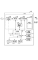
次に、図2を参照して、実施例1に係る給電装置100の構成の一例について説明を行う。給電装置100は、図2に示すように、制御部101、給電部102、メモリ108、表示部109、操作部110、電流検出部111、温度検出部112及び第2の通信部113を有する。給電部102には、電力生成部103、検出部104、整合回路105、第1の通信部106及び給電アンテナ107が含まれる。
Next, an example of the configuration of the
制御部101は、メモリ108に記録されているコンピュータプログラムを実行することによって、給電装置100を制御する。制御部101は、例えば、CPU(Central Processing Unit)やMPU(Micro Processing Unit)を含む。なお、制御部101は、ハードウェアにより構成されるものとする。また、制御部101は、タイマー101aを有する。
The
給電部102は、所定の給電方法に基づいて、無線給電を行うために用いられる。所定の給電方法は、例えば、磁界共鳴方式を用いた給電方法である。磁界共鳴方式とは、給電装置100と電子機器200との間で共振が行われる状態において、給電装置100から電子機器200に電力を伝送するものである。給電装置100と電子機器200との間で共振が行われる状態とは、給電装置100の給電アンテナ107の共振周波数と、電子機器200の受電アンテナ203の共振周波数とが一致している状態である。所定の給電方法は、磁界共鳴方式以外の方式を用いた給電方法であってもよい。
The
電力生成部103は、不図示のAC電源と給電装置100とが接続されている場合、不図示のAC電源から供給される電力を用いて、給電アンテナ107を介して外部に出力するための電力を生成する。
When the AC power supply (not shown) and the
電力生成部103によって生成される電力には、通信電力と、所定の電力とがある。通信電力は、第1の通信部106が電子機器200と通信を行うために用いられる。通信電力は、例えば、1W以下の微弱な電力であるものとする。なお、通信電力は、第1の通信部106の通信規格に規定されている電力であってもよい。所定の電力は、電子機器200が充電や特定の動作を行うために用いられる。所定の電力は、例えば、2W以上の電力であるものとする。また、所定の電力は、通信電力よりも大きい電力であれば、2W以上の電力に限られないものとする。所定の電力の値は、電子機器200から取得したデータに基づいて、制御部101によって設定される。
The power generated by the
電力生成部103によって生成される電力は、検出部104及び整合回路105を介して給電アンテナ107に供給される。
The power generated by the
検出部104は、給電装置100と電子機器200との共振の状態を検出するために、電圧定在波比VSWR(Voltage Standing Wave Ratio)を検出する。さらに、検出部104は、検出したVSWRを示すデータを制御部101に供給する。VSWRは、給電アンテナ107から出力される電力の進行波と、給電アンテナ107から出力される電力の反射波との関係を示す値である。制御部101は、検出部104から供給されたVSWRのデータを用いて、給電装置100と電子機器200との共振の状態の変化や異物の存在を検出することができる。異物とは、例えば、金属やICカード等である。なお、異物は、電池を充電するための充電手段を有していない機器や、給電装置100と通信を行うための通信手段を有していない機器であってもよい。また、異物は、第1の通信部106の通信規格に対応していない機器であってもよい。
The
整合回路105は、給電アンテナ107の共振周波数を設定する回路と、電力生成部103と給電アンテナ107との間のインピーダンスマッチングを行うための回路とを含む。
給電装置100が給電アンテナ107を介して通信電力及び所定の電力のいずれか一つを出力する場合、制御部101は、給電アンテナ107の共振周波数を所定の周波数fに設定するように整合回路105を制御する。所定の周波数fは、例えば、13.56MHzである。また、所定の周波数fは、6.78MHzであってもよく、第1の通信部106の通信規格に規定されている周波数であってもよい。
When the
第1の通信部106は、例えば、NFC(Near Field Communication)フォーラムによって規定されているNFC規格に基づいて、無線通信を行う。また、第1の通信部106の通信規格は、ISO/IEC 18092規格であってもよく、ISO/IEC 14443規格であってもよく、ISO/IEC 21481規格であってもよい。第1の通信部106は、通信電力が給電アンテナ107から出力されている場合、給電アンテナ107を介して電子機器200と無線給電を行うためのデータの送受信を行うことができる。しかし、所定の電力が給電アンテナ107から出力されている期間において、第1の通信部106は、給電アンテナ107を介して電子機器200と通信を行わないものとする。所定の電力が給電アンテナ107から出力されている期間を以下「所定の時間」と呼ぶ。所定の時間は、電子機器200から取得したデータに基づいて、制御部101によって設定される。
For example, the
第1の通信部106と電子機器200との間で送受信されるデータは、NDEF(NFC Data Exchange Format)に対応するデータである。
Data transmitted / received between the
第1の通信部106は、電子機器200にNDEFに対応するデータを送信する場合、電力生成部103から供給される通信電力にデータを重畳する処理を行う。データが重畳された通信電力は、給電アンテナ107を介して電子機器200に送信される。
When transmitting data corresponding to NDEF to the
第1の通信部106が、電子機器200からNDEFに対応するデータを受信する場合、給電アンテナ107に流れる電流を検出し、この電流の検出結果に応じて、電子機器200からデータを受信する。これは、電子機器200が給電装置100にNDEFに対応するデータを送信する場合に、電子機器200の内部の負荷を変動させることによって、データの送信を行うからである。電子機器200の内部の負荷が変化した場合、給電アンテナ107に流れる電流を変化するので、第1の通信部106は、給電アンテナ107に流れる電流を検出することで、電子機器200からNDEFに対応するデータを受信することができる。
When the
なお、第1の通信部106は、NFC規格に規定されているリーダライタとして動作するものとする。
Note that the
給電アンテナ107は、通信電力及び所定の電力のいずれか一つを電子機器200に出力するためのアンテナである。また、給電アンテナ107は、第1の通信部106がNFC規格を用いた無線通信を電子機器200と行うために用いられる。
The
メモリ108は、給電装置100を制御するためのコンピュータプログラムを記録する。さらに、メモリ108は、給電装置100の識別データ、給電装置100に関する給電パラメータや給電を制御するためのフラグ等を記録する。また、メモリ108は、電子機器200から第1の通信部106及び第2の通信部113の少なくとも一つが取得したデータを記録する。
The
表示部109は、メモリ108及び第2の通信部113から供給される映像データを表示する。
The
操作部110は、給電装置100を操作するためのユーザインターフェースを提供する。操作部110は、給電装置100を操作するためのボタン、スイッチやタッチパネル等を有する。制御部101は、操作部110を介して入力された入力信号に従って給電装置100を制御する。
The
電流検出部111は、給電アンテナ107に流れる電流を検出し、検出した電流を示すデータを制御部101に供給する。制御部101は、電流検出部111から供給された電流のデータを用いて、異物の存在を検出することができる。
The
温度検出部112は、給電装置100の温度を検出し、検出した温度を示すデータを制御部101に供給する。制御部101は、温度検出部112から供給された温度のデータを用いて、異物の存在を検出することができる。なお、温度検出部112によって検出される給電装置100の温度は、給電装置100内部の温度であってもよく、給電装置100の表面の温度であってもよい。
The
第2の通信部113は、第1の通信部106の通信規格と異なる通信規格に基づいて、電子機器200と無線通信を行う。第2の通信部113の通信規格は、例えば、無線LAN(Wireless Local Area Network)規格やBlue Tooth(登録商標)規格である。第2の通信部113は、給電装置100と電子機器200との間で映像データ、音声データ及びコマンドの少なくとも一つを含むデータを送信したり受信することができる。
The
給電装置100は、無線により電力を電子機器200に供給するようにした。しかし、「無線」を「非接触」や「無接点」と言い換えてもよいものとする。
The
次に、図3を参照して、電子機器200の構成の一例について説明を行う。電子機器200は、制御部201、受電部202、電力検出部207、レギュレータ208、負荷部209、充電部210、電池211、温度検出部212、メモリ213、操作部214及び第2の通信部215を有する。受電部202には、受電アンテナ203、整合回路204、整流平滑回路205、及び第1の通信部206が含まれる。
Next, an example of the configuration of the
制御部201は、メモリ213に記録されているコンピュータプログラムを実行することによって、電子機器200を制御する。制御部201は、例えば、CPUやMPUを含む。なお、制御部201は、ハードウェアにより構成されるものとする。
The
受電部202は、所定の給電方法に対応し、給電装置100から電力を無線により受け取るために用いられる。
The
受電アンテナ203は、給電装置100から供給される電力を受け取るためのアンテナである。また、受電アンテナ203は、第1の通信部206がNFC規格を用いた無線通信を給電装置100と行うために用いられる。受電アンテナ203を介して給電装置100から電子機器200が受け取った電力は、整合回路204を介して整流平滑回路205に供給される。
The
整合回路204は、受電アンテナ203の共振周波数を設定する回路を含む。制御部201は、整合回路204を制御することによって受電アンテナ203の共振周波数を設定することができる。
The
整流平滑回路205は、受電アンテナ203によって受電された電力から直流電力を生成する。さらに、整流平滑回路205は、生成した直流電力を電力検出部207を介してレギュレータ208に供給する。受電アンテナ203によって受電された電力にデータが重畳されている場合、受電アンテナ203によって受電された電力から取り除かれたデータを第1の通信部206に供給する。
The rectifying /
第1の通信部206は、第1の通信部106と同一の通信規格に基づいて、給電装置100と通信を行う。第1の通信部206は、メモリ206aを有する。メモリ206aには、WPT(Wireless Power Transfer)用RTD(Record Type Definiton)データ400が記録されている。WPT用RTDデータ400には、NDEFに対応するデータが複数格納されている。WPT用RTDデータ400には、給電装置100と電子機器200との間で無線給電を行うために必要なデータが格納される。給電装置100と電子機器200との間で無線給電を行うために必要なデータは、NDEFに対応する。
The
WPT用RTDデータ400には、少なくとも無線給電の認証を給電装置100と行うために用いられる認証データが格納されている。認証データには、レコードタイプ名、電子機器200が対応している給電方法や給電の制御プロトコルを示すデータや電子機器200の識別データ、電子機器200の受電能力データ、電子機器200が持っているタグの種類を示すデータ等が含まれる。レコードタイプ名とは、WPT用RTDデータ400に格納されているデータの内容や構造を識別するためのレコードタイプ(record type)を示すデータである。レコードタイプ名(record type name)は、WPT用RTDデータ400を識別するためのデータである。受電能力データは、電子機器200の受電能力を示すデータであり、例えば、電子機器200の受電可能な電力の最大値を示す。
The WPT RTD data 400 stores at least authentication data used to perform authentication of wireless power supply with the
WPT用RTDデータ400には、さらに受電ステータスデータや給電ステータスデータが格納されていてもよい。受電ステータスデータには、電子機器200の状態を示すデータが含まれる。例えば、受電ステータスデータには、給電装置100に要求する要求電力の値、電子機器200が給電装置100から受け取った電力の値、電池211の残容量や電池211の充電に関するデータ、電子機器200のエラーに関するエラーデータ等が含まれる。エラーデータには、電子機器200にエラーが発生しているか否かを示すデータと、エラーの種類を示すデータとが含まれる。給電ステータスデータには、給電装置100の状態を示すデータが含まれる。例えば、給電ステータスデータには、給電装置100の識別データ、給電装置100が電子機器200への所定の電力の伝送を開始するか否かを示すデータ、給電装置100で設定された給電パラメータ等が含まれる。
The WPT RTD data 400 may further store power reception status data and power supply status data. The power reception status data includes data indicating the state of the
第1の通信部206は、整流平滑回路205から供給されたデータを解析する。その後、第1の通信部206は、データの解析結果を用いて、WPT用RTDデータ400から読み出したデータを給電装置100に送信したり、給電装置100から受信したデータをWPT用RTDデータ400に書き込んだりする。さらに、第1の通信部206は、整流平滑回路205から供給されたデータに対応する応答データを給電装置100に送信する。
The
第1の通信部206は、WPT用RTDデータ400から読み出したデータや応答データを給電装置100に送信するために、第1の通信部206内部の負荷を変動させる処理を行う。
The
電子機器200は、NFC規格に規定されているタグに対応するものとする。電子機器200の対応可能なタグの種類として、第1のタグと、第2のタグとがある。以下、第1のタグ及び第2のタグにについて、図4を用いて説明を行う。図4は、図4(a)に第1のタグを示し、図4(b)に第2のタグを示す。
The
図4(a)を参照し、第1のタグについて説明を行う。図4の(a)のWPT用RTDデータ400には、電子機器200が第1のタグを持っていることを示すデータを含む識別データが格納されている。電子機器200が第1のタグを持っている場合、制御部201は、不図示の内部バスインターフェースを介してWPT用RTDデータ400に格納されているデータを読み出すことができる。さらに、電子機器200が第1のタグを持っている場合、制御部201は、不図示の内部バスインターフェースを介してWPT用RTDデータ400にデータを書き込むことができる。
The first tag will be described with reference to FIG. In the WPT RTD data 400 of FIG. 4A, identification data including data indicating that the
電子機器200が第1のタグを持っている場合、例えば、制御部201は、WPT用RTDデータ400から読み出された給電ステータスデータを用いて、電子機器200の各部を制御することができる。電子機器200が第1のタグを持っている場合、例えば、制御部201は、電子機器200の各部から供給されるデータを用いて受電ステータスデータを定期的に検出し、検出した受電ステータスデータをWPT用RTDデータ400に書き込むことができる。なお、第1のタグは、「アクティブタグ」や「ダイナミックタグ」と言い換えても良いものとする。図4(a)のように、電子機器200が第1のタグを持っている場合におけるWPT用RTDデータ400には、識別データ、受電ステータスデータ及び給電ステータスデータが格納される。
When the
図4(b)を参照し、第2のタグについて説明を行う。図4の(b)のWPT用RTDデータ400には、電子機器200が第2のタグを持っていることを示すデータを含む識別データが格納されている。電子機器200が第2のタグを持っている場合、制御部201は、WPT用RTDデータ400に格納されているデータを読み出すことができず、WPT用RTDデータ400にデータを書き込むこともできない。この場合、例えば、制御部201は、WPT用RTDデータ400に格納されている給電ステータスデータを用いて電子機器200を制御することができず、受電ステータスデータをWPT用RTDデータ400に書き込んだり、追記することもできない。図4(b)のように、電子機器200が第2のタグを持っている場合におけるWPT用RTDデータ400には、識別データは格納されているが、受電ステータスデータは格納されないものとする。また、電子機器200が第2のタグを持っている場合におけるWPT用RTDデータ400には、給電ステータスデータが格納されていてもよい。
The second tag will be described with reference to FIG. In the WPT RTD data 400 in FIG. 4B, identification data including data indicating that the
なお、電子機器200が第1のタグ及び第2のタグの少なくとも一つを持っている場合、給電装置100は、第1の通信部106を用いてWPT用RTDデータ400に格納されているデータを読み出すことができる。さらに、この場合、給電装置100は、第1の通信部106を用いてデータをWPT用RTDデータ400に書き込むこともできる。
Note that when the
なお、実施例1において、電子機器200は、第1のタグを持っているものとして、電子機器200の構成の説明を行う。
In the first embodiment, the configuration of the
電力検出部207は、受電アンテナ203を介して受け取った電力を検出し、検出した電力を示すデータを制御部201に供給する。
The
制御部201は、電力検出部207から供給された電力のデータを用いて、電子機器200に第1のエラーが発生しているか否かを判定する。第1のエラーとは、例えば、電子機器200の受電可能な電力の最大値よりも大きい電力を電子機器200が給電装置100から受け取った場合に発生するエラーである。
The
例えば、制御部201は、電子機器200の受電可能な電力の最大値と、電力検出部207で検出された電力の値とを比較し、比較の結果を用いて、電子機器200に第1のエラーが発生しているか否かを判定する。電力検出部207で検出された電力が電子機器200の受電可能な電力の最大値よりも大きい場合、制御部201は、第1のエラーが電子機器200に発生していると判定する。電力検出部207で検出された電力が電子機器200の受電可能な電力の最大値以下である場合、制御部201は、第1のエラーが電子機器200に発生していないと判定する。第1のエラーが電子機器200に発生していると判定された場合、制御部201は、電子機器200にエラーが発生していることを示すデータと、第1のエラーを示すデータとを含む受電ステータスデータをWPT用RTDデータ400に書き込む。
For example, the
さらに、制御部201は、電力検出部207から供給された電力のデータを用いて、電子機器200に第2のエラーが発生しているか否かを判定する。第2のエラーとは、例えば、電子機器200が給電装置100に対して要求する要求電力に対して電子機器200が給電装置100から受け取った電力が足りない場合に発生するエラーである。
Further, the
例えば、制御部201は、要求電力の値と、電力検出部207で検出された電力の値とを比較し、比較の結果を用いて、電子機器200に第2のエラーが発生しているか否かを判定する。
For example, the
電力検出部207で検出された電力の値が、要求電力の値よりも小さい場合、制御部201は、第2のエラーが電子機器200に発生していると判定する。電力検出部207で検出された電力の値が、要求電力の値以上である場合、制御部201は、第2のエラーが電子機器200に発生していないと判定する。第2のエラーが電子機器200に発生していると判定された場合、制御部201は、電子機器200にエラーが発生していることを示すデータと、第2のエラーを示すデータとを含む受電ステータスデータをWPT用RTDデータ400に書き込む。
When the value of the power detected by the
レギュレータ208は、制御部201からの指示に応じて、整流平滑回路205から供給される電力及び電池211から供給される電力の少なくとも一つを電子機器200の各部に供給する。
The
負荷部209は、被写体の光学像から静止画や動画等の映像データの生成を行う撮像回路や映像データの再生を行う再生回路等を有する。
The
充電部210は、電池211を充電する。充電部210は、制御部201からの指示に応じて、レギュレータ208から供給される電力を用いて電池211を充電するか、電池211から放電される電力をレギュレータ208に供給するかを制御する。充電部210は、定期的に電池211の残容量を検出し、電池211の残容量を示すデータや電池211の充電に関するデータを制御部201に供給する。
Charging
電池211は、電子機器200に接続可能な電池である。また、電池211は、充電可能な二次電池であり、例えば、リチウムイオン電池等である。なお、電池211は、リチウムイオン電池以外のものであっても良いものとする。
The
制御部201は、電子機器200と電池211とが接続されているか否かに応じて、電子機器200に第3のエラーが発生しているか否かを判定する。第3のエラーとは、例えば、電子機器200に電池211が接続されていない場合に発生するエラーである。電子機器200と電池211とが接続されていない場合、制御部201は、電子機器200に第3のエラーが発生していると判定する。電子機器200と電池211とが接続されている場合、制御部201は、電子機器200に第3のエラーが発生していないと判定する。第3のエラーが電子機器200に発生していると判定された場合、制御部201は、電子機器200にエラーが発生していることを示すデータと、第3のエラーを示すデータとを含む受電ステータスデータをWPT用RTDデータ400に書き込む。
The
温度検出部212は、電子機器200の温度を検出し、検出した温度を示すデータを制御部201に供給する。制御部201は、温度検出部212から供給された温度のデータを用いて、電子機器200に第4のエラーが発生しているか否かを判定する。第4のエラーとは、例えば、電子機器200内の温度が高温になった場合に発生するエラーである。
The
制御部201は、設定値と、温度検出部212で検出された温度とを比較し、比較の結果を用いて、電子機器200に第4のエラーが発生しているか否かを判定する。設定値は、例えば、電池211の充電を正常に行うために設定されている温度の上限値である。また、設定値は、例えば、受電部202や負荷部209を保護するために設定されている温度の上限値であってもよい。温度検出部212で検出された温度が設定値よりも高い場合、制御部201は、第4のエラーが電子機器200に発生していると判定する。温度検出部212で検出された温度が設定値以下である場合、制御部201は、第4のエラーが電子機器200に発生していないと判定する。第4のエラーが電子機器200に発生していると判定された場合、制御部201は、電子機器200にエラーが発生していることを示すデータと、第4のエラーを示すデータとを含む受電ステータスデータをWPT用RTDデータ400に書き込む。
The
メモリ213は、電子機器200を制御するコンピュータプログラム及電子機器200に関するパラメータ等のデータを記憶する。
The
操作部214は、電子機器200を操作するためのユーザインターフェースを提供する。制御部201は、操作部214を介して入力された入力信号に従って電子機器200を制御する。
The
第2の通信部215は、給電装置100と無線通信を行う。なお、第2の通信部215は、例えば、第2の通信部113と同一の通信規格に基づいて、給電装置100と無線通信を行う。
The second communication unit 215 performs wireless communication with the
(給電装置100の状態遷移図)
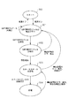
実施例1における給電装置100の状態の遷移について、図5を用いて説明する。図5において、状態500は、不図示のAC電源と給電装置100とが接続されている状態で、かつ、給電装置100の電源がオフである状態である。給電装置100が状態500の場合に、操作部110を用いて給電装置100の電源がオンにされたとき、給電装置100は、状態501に遷移する。
(State transition diagram of power supply apparatus 100)
The state transition of the
状態501において、給電装置100は、WPT用RTDデータを検出する処理を行う。給電装置100が状態501である場合に、給電装置100の電源がオフにされたとき、給電装置100は、状態500に遷移する。給電装置100が状態501である場合に、給電装置100がWPT用RTDデータを検出したとき、給電装置100は、状態502に遷移する。給電装置100がWPT用RTDデータを検出していない場合、または、給電装置100がWPT用RTDデータと異なるRTDデータを検出した場合、給電装置100は、WPT用RTDデータ400を検出するまでは、状態501を維持する。
In the
状態502において、給電装置100は、検出したWPT用RTDデータを解析する処理を行う。給電装置100が状態502である場合に、WPT用RTDデータの解析の結果、給電装置100と電子機器200との無線給電の認証が成功したとき、給電装置100は、状態503に遷移する。給電装置100が状態502である場合に、無線給電に関するエラーが発生した場合、給電装置100は、状態501に遷移する。無線給電に関するエラーとは、例えば、給電装置100と電子機器200との通信に関する通信エラー、異物に関するエラー、電子機器200に関するエラー、給電装置100と電子機器200との無線給電の認証に関する認証エラー等である。
In the
状態503において、給電装置100は、無線給電を行うために必要なステータスデータを電子機器200と交換する処理を行う。給電装置100が状態503である場合、給電装置100は、電子機器200から受電ステータスデータを受信し、電子機器200に給電ステータスデータを送信する。給電装置100が状態503である場合に、ステータスデータの交換が完了したとき、給電装置100は、状態504に遷移する。給電装置100が状態503である場合に、無線給電に関するエラーが発生した場合、給電装置100は、状態501に遷移する。給電装置100が状態503である場合に、電子機器200の充電が完了したことが検出された場合、給電装置100は、状態501に遷移する。
In the
状態504において、給電装置100は、所定の電力を電子機器200に供給するための給電処理を行う。給電装置100が状態504である場合に、無線給電に関するエラーが発生したとき、給電装置100は、状態504から状態503に遷移する。給電装置100が状態504である場合に、所定の電力の出力が開始されてから所定の時間が経過した後、給電装置100は、状態503に遷移する。
In the
(制御処理)
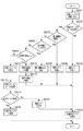
次に、実施例1において、給電装置100の無線給電を制御するための制御処理について、図6のフローチャートを用いて説明する。制御処理は、制御部101がメモリ108に格納されているコンピュータプログラムを実行することにより実現することができる。
(Control processing)
Next, control processing for controlling wireless power feeding of the
S601において、制御部101は、給電装置100の電源がオンであるか否かを検出する。給電装置100の電源がオンであることが検出された場合(S601でYes)、本フローチャートは、S602に進む。給電装置100の電源がオンでないことが検出された場合(S601でNo)、本フローチャートは終了する。
In step S <b> 601, the
S602において、制御部101は、後述の認証処理を行う。認証処理が行われた場合、本フローチャートは、S603に進む。
In step S602, the
S603において、制御部101は、給電装置100と電子機器200との無線給電の認証が成功したか否かを判定する。S602で認証処理が行われた場合、メモリ108に認証成功フラグ及び認証失敗フラグのいずれか一つが設定される。メモリ108に認証成功フラグが設定されている場合、制御部101は、無線給電の認証が成功したと判定し(S603でYes)、本フローチャートはS604に進む。メモリ108に認証失敗フラグが設定されている場合、制御部101は、無線給電の認証が失敗したと判定し(S603でNo)、本フローチャートはS608に進む。
In step S <b> 603, the
S604において、制御部101は、後述のステータスデータ交換処理を行う。ステータスデータ交換処理が行われた場合、本フローチャートは、S605に進む。
In step S604, the
S605において、制御部101は、給電装置100が電子機器200への給電を行うことができるか否かを判定する。S604でステータスデータ交換処理が行われた場合、メモリ108に給電可能フラグ及び給電不可フラグのいずれか一つが設定される。メモリ108に給電可能フラグが設定されている場合、制御部101は、給電装置100が電子機器200への給電を行うことができると判定し(S605でYes)、本フローチャートはS606に進む。メモリ108に給電不可フラグが設定されている場合、制御部101は、給電装置100が電子機器200への給電を行うことができないと判定し(S605でNo)、本フローチャートはS608に進む。
In step S <b> 605, the
S606において、制御部101は、後述の給電処理を行う。給電処理が行われた場合、本フローチャートは、S607に進む。
In step S606, the
S607において、制御部101は、給電装置100が電子機器200への給電を継続して行う否かを判定する。S606で給電処理が行われた場合、メモリ108に給電継続フラグ及び給電停止フラグのいずれか一つが設定される。メモリ108に給電継続フラグが設定されている場合、制御部101は、給電装置100が電子機器200への給電を継続して行うと判定し(S607でYes)、本フローチャートはS604に戻る。メモリ108に給電停止フラグが設定されている場合、制御部101は、給電装置100が電子機器200への給電を継続して行わないと判定し(S607でNo)、本フローチャートはS608に進む。
In step S <b> 607, the
S608において、制御部101は、メモリ108に格納されている給電パラメータや給電の制御に関するフラグ等を消去する。この場合、本フローチャートは、S601に戻る。
In step S <b> 608, the
(認証処理)
次に、実施例1において、図6のS602において、制御部101によって行われる認証処理について、図7のフローチャートを用いて説明する。認証処理は、制御部101がメモリ108に格納されているコンピュータプログラムを実行することにより実現することができる。
(Authentication process)
Next, in the first embodiment, the authentication process performed by the
S701において、制御部101は、通信電力を出力するように給電部102を制御する。なお、制御部101は、所定の電力を出力する処理を開始するまで、通信電力が給電アンテナ107を介して出力されるようにする。さらに、制御部101は、給電アンテナ107の共振周波数を所定の周波数fに設定するように整合回路105を制御する。この場合、本フローチャートは、S702に進む。
In step S701, the
S702において、制御部101は、認証データを要求するデータを送信するように第1の通信部106を制御する。この場合、本フローチャートは、S703に進む。
In step S <b> 702, the
S703において、制御部101は、WPT用RTDデータ400を検出したか否かを判定する。第1の通信部106が電子機器200から認証データを受信した場合、制御部101は、電子機器200の認証データから電子機器200のレコードタイプ名を取得する。その後、制御部101は、電子機器200のレコードタイプ名に基づいて、WPT用RTDデータ400を検出したか否かを判定する。WPT用RTDデータ400が検出された場合(S703でYes)、本フローチャートはS704に進む。WPT用RTDデータ400が検出されていない場合(S703でNo)、本フローチャートはS702に戻る。なお、第1の通信部106が電子機器200から認証データを受信していない場合も、本フローチャートはS702に戻る。
In step S <b> 703, the
S704において、制御部101は、電子機器200の認証データに含まれるデータを確認することで、電子機器200のWPT用RTDデータ400を解析する。この場合、本フローチャートはS705に進む。
In step S <b> 704, the
S705において、制御部101は、S704の解析結果を用いて、電子機器200の認証データに通信エラーが発生しているか否かを検出する。電子機器200の認証データに通信エラーが検出された場合(S705でYes)、本フローチャートは、S706に進む。電子機器200の認証データに通信エラーが検出されていない場合(S705でNo)、本フローチャートは、S708に進む。
In step S <b> 705, the
S706において、制御部101は、給電装置100と電子機器200との間における通信のエラーが検出されたことを示すデータを表示部109に表示させる。この場合、本フローチャートは、S707に進む。
In step S <b> 706, the
S707において、制御部101は、メモリ108に認証失敗フラグを設定する。この場合、本フローチャートは終了し、図6のS603に進む。
In step S <b> 707, the
所定の範囲300内に異物が置かれた場合、検出部104で検出されるVSWRが急激に変化する場合がある。そこで、給電装置100は、所定の範囲300内に異物が存在しているか否かを判定するために、S708の処理を行う。
When a foreign object is placed within the
S708において、制御部101は、検出部104で検出されるVSWRが所定値以上変化したか否かを検出する。所定値は、異物の存在を識別するための閾値である。検出部104で検出されるVSWRが所定値以上変化した場合(S708でYes)、本フローチャートは、S709に進む。検出部104で検出されるVSWRが所定値以上変化していない場合(S708でNo)、本フローチャートは、S710に進む。
In step S708, the
S709において、制御部101は、異物が検出されたことを通知するためのデータを表示部109に表示させる。この場合、本フローチャートは、S707に進む。
In step S709, the
S710において、制御部101は、S704の解析結果を用いて、電子機器200が給電装置100に対応しているか否かを判定する。
In step S <b> 710, the
例えば、制御部101は、給電装置100が対応してる給電方法と電子機器200が対応している給電方法とが一致している場合、電子機器200が給電装置100に対応していると判定する。また、制御部101は、給電装置100が対応してる給電方法と電子機器200が対応している給電方法とが一致していない場合、電子機器200が給電装置100に対応していないと判定する。
For example, the
また、例えば、制御部101は、給電装置100が対応してる給電の制御プロトコルと電子機器200が対応している給電の制御プロトコルとが一致している場合、電子機器200が給電装置100に対応していると判定する。また、給電装置100が対応してる給電の制御プロトコルと電子機器200が対応している給電の制御プロトコルとが一致していない場合、電子機器200が給電装置100に対応していないと判定する。
For example, when the power supply control protocol supported by the
電子機器200が給電装置100に対応していない場合(S710でNo)、本フローチャートは、S711に進む。電子機器200が給電装置100に対応している場合(S710でYes)、本フローチャートは、S712に進む。
When the
S711において、制御部101は、給電装置100と電子機器200との間における認証のエラーが検出されたことを示すデータを表示部109に表示させる。この場合、本フローチャートは、S707に進む。
In step S <b> 711, the
S712において、制御部101は、S704の解析結果を用いて、電子機器200が第1のタグを持っているか否かを判定する。制御部101は、電子機器200の認証データに電子機器200が第1のタグを持っていることを示すデータが含まれているか否かに応じて、電子機器200が第1のタグを持っているか否かを判定する。電子機器200の認証データに電子機器200が第1のタグを持っていることを示すデータが含まれている場合、制御部101は、電子機器200が第1のタグを持っていると判定し(S712でYes)、本フローチャートは、S713に進む。電子機器200の認証データに電子機器200が第1のタグを持っていることを示すデータが含まれていない場合、制御部101は、電子機器200が第1のタグを持っていないと判定し(S712でNo)、本フローチャートは、S711に進む。
In step S712, the
S713において、制御部101は、メモリ108に認証成功フラグを設定する。この場合、本フローチャートは終了し、図6のS603に進む。
In step S <b> 713, the
なお、S701とS702の間に、制御部101は、NFC規格のNFCデジタルプロトコル(NFC Digital Protocol)において規定されている処理を行ってもよい。
In addition, between S701 and S702, the
また、S708において、制御部101は、検出部104で検出されるVSWRが所定値以上変化したか否かを検出するようにしたが、これに限られないものとする。
In S708, the
所定の範囲300内に異物が置かれた場合、電流検出部111で検出される電流が急激に上昇する場合がある。そこで、S708において、制御部101は、電流検出部111で検出される電流が所定の電流値以上であるか否かを検出するようにしてもよい。なお、所定の電流値は、異物の存在を識別するための閾値である。
When a foreign object is placed within the
電流検出部111で検出される電流が所定の電流値以上である場合は、VSWRが所定値以上変化した場合(S708でYes)と同様に、図7のフローチャートは、S708からS709に進む。電流検出部111で検出される電流が所定の電流値以上でない場合は、VSWRが所定値以上変化していない場合(S708でNo)と同様に、図7のフローチャートは、S708からS710に進む。
When the current detected by the
また、所定の範囲300内に異物が置かれた場合、温度検出部112で検出される温度が急激に上昇する場合がある。そこで、S708において、制御部101は、温度検出部112で検出される温度が所定の温度以上であるか否かを検出するようにしてもよい。なお、所定の温度は、異物の存在を識別するための閾値である。
In addition, when a foreign object is placed within the
温度検出部112で検出される温度が所定の温度以上である場合は、VSWRが所定値以上変化した場合(S708でYes)と同様に、図7のフローチャートは、S708からS709に進む。温度検出部112で検出される温度が所定の温度以上でない場合は、VSWRが所定値以上変化していない場合(S708でNo)と同様に、図7のフローチャートは、S708からS710に進む。
When the temperature detected by the
(ステータスデータ交換処理)
次に、実施例1において、図6のS604において、制御部101によって行われるステータスデータ交換処理について、図8のフローチャートを用いて説明する。ステータスデータ交換処理は、制御部101がメモリ108に格納されているコンピュータプログラムを実行することにより実現することができる。
(Status data exchange process)
Next, in Example 1, the status data exchange process performed by the
S801において、制御部101は、受電ステータスデータを要求するデータを送信するように第1の通信部106を制御する。この場合、本フローチャートは、S802に進む。
In step S801, the
S802において、制御部101は、電子機器200に受電ステータスデータの要求が行われてから一定の時間が経過するまでの間に、第1の通信部106が電子機器200から受電ステータスデータを受信したか否かを判定する。第1の通信部106が電子機器200から受電ステータスデータを受信したと判定された場合(S802でYes)、本フローチャートは、S805に進む。受電ステータスデータの要求が行われてから一定の時間が経過した場合であっても、第1の通信部106が電子機器200から受電ステータスデータを受信していないと判定された場合(S802でNo)、本フローチャートは、S803に進む。
In step S <b> 802, the
S803において、制御部101は、S706と同様に、通信のエラーが検出されたことを示すデータを表示部109に表示させる。この場合、本フローチャートは、S804に進む。
In step S803, the
S804において、制御部101は、メモリ108に給電不可フラグを設定する。この場合、本フローチャートは終了し、図6のS605に進む。
In step S <b> 804, the
S805において、制御部101は、第1の通信部106が受信した受電ステータスデータを用いて、電子機器200の充電が完了したか否かを判定する。電子機器200の充電が完了したと判定された場合(S805でYes)、本フローチャートは、S806に進む。電子機器200の充電が完了していないと判定された場合(S805でNo)、本フローチャートは、S807に進む。
In step S <b> 805, the
S806において、制御部101は、電子機器200の充電が完了したことを示すデータを表示部109に表示させる。また、制御部101は、電池211が満充電であることを示すデータを表示部109に表示させてもよい。この場合、本フローチャートは、S804に進む。
In step S806, the
S807において、制御部101は、第1の通信部106が受信した受電ステータスデータを用いて、電子機器200にエラーが発生しているか否かを判定する。例えば、制御部101は、電子機器200の受電ステータスデータからエラーデータを検出し、エラーデータを解析することで、電子機器200にエラーが発生しているか否かを判定する。
In step S <b> 807, the
電子機器200にエラーが発生していると判定された場合(S807でYes)、本フローチャートは、S808に進む。電子機器200にエラーが発生していないと判定された場合(S807でNo)、本フローチャートは、S809に進む。 If it is determined that an error has occurred in the electronic device 200 (Yes in S807), the flowchart proceeds to S808. When it is determined that no error has occurred in the electronic device 200 (No in S807), the flowchart proceeds to S809.
S808において、制御部101は、電子機器200にエラーが発生したことを示すデータを表示部109に表示させる。さらに、制御部101は、電子機器200に発生したエラーの種類を示すデータを表示部109に表示させてもよい。
この場合、本フローチャートは、S804に進む。
In step S808, the
In this case, the flowchart proceeds to S804.
S809において、制御部101は、S708と同様に、検出部104で検出されるVSWRが所定値以上変化したか否かを検出する。検出部104で検出されるVSWRが所定値以上変化した場合(S809でYes)、本フローチャートは、S810に進む。検出部104で検出されるVSWRが所定値以上変化していない場合(S809でNo)、本フローチャートは、S812に進む。
In step S809, the
S810において、制御部101は、異物を検出したことを電子機器200に通知するデータを送信するように第1の通信部106を制御する。この場合、本フローチャートは、S811に進む。
In step S810, the
S811において、制御部101は、異物が検出されたことを通知するためのデータを表示部109に表示させる。この場合、本フローチャートは、S804に進む。
In step S811, the
S812において、制御部101は、第1の通信部106が受信した受電ステータスデータを用いて、給電パラメータを設定する。給電パラメータとは、所定の電力の値及び所定の時間である。例えば、制御部101は、電子機器200から要求されている電力と、給電装置100から電子機器200への給電効率に基づいて、所定の電力の値及び所定の時間を設定する。給電装置100から電子機器200への給電効率とは、給電装置100が出力する電力に対して電子機器200が受け取る電力の割合を示す。また、例えば、制御部101は、電池211の残容量に基づいて、所定の電力の値及び所定の時間を設定してもよい。制御部101は、設定した給電パラメータをメモリ108に格納する。この場合、本フローチャートは、S813に進む。
In step S812, the
S813において、制御部101は、給電ステータスデータを電子機器200に送信するように第1の通信部106を制御する。制御部101は、給電装置100の識別データ、S812で設定された給電パラメータ及び電子機器200への所定の電力の伝送を開始することを示すデータを含む給電ステータスデータを生成する。さらに、制御部101は、生成した給電ステータスデータを電子機器200に送信するように第1の通信部106を制御する。この場合、本フローチャートは、S814に進む。
In step S813, the
給電装置100から送信された給電ステータスデータがWPT用RTDデータ400に格納された場合、第1の通信部206は、給電ステータスデータが正常にWPT用RTDデータ400に書き込まれたことを示す応答データを給電装置100に送信する。
When the power supply status data transmitted from the
そこで、S814において、制御部101は、給電ステータスデータが送信されてから一定の時間が経過するまでの間に、第1の通信部106が電子機器200から応答データを受信したか否かを判定する。第1の通信部106が電子機器200から応答データを受信したと判定された場合(S814でYes)、本フローチャートは、S816に進む。給電ステータスデータが送信されてから一定の時間が経過した場合であっても、第1の通信部106が電子機器200から応答データを受信していないと判定された場合(S814でNo)、本フローチャートは、S815に進む。なお、第1の通信部106が電子機器200から受信した応答データが、給電ステータスデータが正常にWPT用RTDデータ400に書き込まれていないことを示している場合も、本フローチャートは、S815に進む。
Therefore, in S814, the
S815において、制御部101は、S706と同様に、通信のエラーが検出されたことを示すデータを表示部109に表示させる。この場合、本フローチャートは、S804に進む。
In step S815, the
S816において、制御部101は、メモリ108に給電可能フラグを設定する。この場合、本フローチャートは終了し、図6のS605に進む。
In step S <b> 816, the
また、S809において、制御部101は、検出部104で検出されるVSWRが所定値以上変化したか否かを検出するようにしたが、これに限られないものとする。
In S809, the
S809において、制御部101は、電流検出部111で検出される電流が所定の電流値以上であるか否かを検出するようにしてもよい。電流検出部111で検出される電流が所定の電流値以上である場合は、VSWRが所定値以上変化した場合(S809でYes)と同様に、図8のフローチャートは、S809からS810に進む。電流検出部111で検出される電流が所定の電流値以上でない場合は、VSWRが所定値以上変化していない場合(S809でNo)と同様に、図8のフローチャートは、S809からS812に進む。
In step S809, the
また、S809において、制御部101は、温度検出部112で検出される温度が所定の温度以上であるか否かを検出するようにしてもよい。温度検出部112で検出される温度が所定の温度以上である場合は、VSWRが所定値以上変化した場合(S809でYes)と同様に、図8のフローチャートは、S809からS810に進む。温度検出部112で検出される温度が所定の温度以上でない場合は、VSWRが所定値以上変化していない場合(S809でNo)と同様に、図8のフローチャートは、S809からS812に進む。
In S809, the
(給電処理)
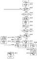
次に、実施例1において、図6のS606において、制御部101によって行われる給電処理について、図9のフローチャートを用いて説明する。給電処理は、制御部101がメモリ108に格納されているコンピュータプログラムを実行することにより実現することができる。
(Power supply processing)
Next, in Embodiment 1, the power supply process performed by the
S901において、制御部101は、S812で設定された給電パラメータに応じて、所定の電力を出力するように給電部102を制御する。さらに、制御部101は、給電アンテナ107の共振周波数を所定の周波数fに設定するように整合回路105を制御する。さらに、制御部101は、所定の電力が出力されてから経過した時間を計測するようにタイマー101aを制御する。この場合、本フローチャートは、S902に進む。
In step S <b> 901, the
S902において、制御部101は、タイマー101aによって計測された時間に応じて、所定の電力が出力されてから所定の時間が経過したか否かを判定する。タイマー101aによって計測された時間が所定の時間以上である場合、制御部101は、所定の電力が出力されてから所定の時間が経過したと判定し(S902でYes)、本フローチャートは、S918に進む。タイマー101aによって計測された時間が所定の時間以上でない場合、制御部101は、所定の電力が出力されてから所定の時間が経過していないと判定し(S902でNo)、本フローチャートは、S903に進む。
In step S902, the
S903において、制御部101は、S708と同様に、検出部104で検出されるVSWRが所定値以上変化したか否かを検出する。検出部104で検出されるVSWRが所定値以上変化した場合(S903でYes)、本フローチャートは、S904に進む。検出部104で検出されるVSWRが所定値以上変化していない場合(S903でNo)、本フローチャートは、S901に戻る。
In S903, the
S904において、制御部101は、所定の電力の出力を停止するように給電部102を制御する。この場合、本フローチャートは、S905に進む。
In step S904, the
S905において、制御部101は、通信電力を出力するように給電部102を制御する。さらに、制御部101は、給電アンテナ107の共振周波数を所定の周波数fに設定するように整合回路105を制御する。この場合、本フローチャートは、S906に進む。
In step S905, the
S906において、制御部101は、S801と同様に、受電ステータスデータを要求するデータを送信するように第1の通信部106を制御する。この場合、本フローチャートは、S907に進む。
In step S906, the
S907において、制御部101は、S802と同様に、電子機器200に受電ステータスデータの要求が行われてから一定の時間が経過するまでの間に、第1の通信部106が電子機器200から受電ステータスデータを受信したか否かを判定する。第1の通信部106が電子機器200から受電ステータスデータを受信したと判定された場合(S907でYes)、本フローチャートは、S911に進む。受電ステータスデータの要求が行われてから一定の時間が経過した場合であっても、第1の通信部106が電子機器200から受電ステータスデータを受信していないと判定された場合(S907でNo)、本フローチャートは、S908に進む。
In S907, as in S802, the
第1の通信部106が電子機器200から受電ステータスデータを受信していない場合(S907でNo)、電子機器200が所定の範囲300から取り外された可能性がある。また、第1の通信部106が電子機器200から受電ステータスデータを受信していない場合(S907でNo)、電子機器200の第1の通信部206が通信を行うことができない状態に変化した可能性がある。
When the
そこで、S908において、制御部101は、第1の警告データを表示部109に表示させる。第1の警告データは、例えば、第1の通信部106と第1の通信部206とによる通信が行えなくなったことにより給電装置100が電子機器200への所定の電力の供給を停止することとをユーザに通知するためのデータである。さらに、第1の警告データは、電子機器200に再び所定の電力を供給するために、電子機器200を所定の範囲300内に置くようにユーザに促すためのデータであってもよい。さらに、第1の警告データは、電子機器200に再び所定の電力を供給するために、操作部110で給電装置100を操作するようにユーザに促すためのデータであってもよい。第1の警告データが表示された場合、本フローチャートは、S909に進む。
Therefore, in S908, the
S909において、制御部101は、給電ステータスデータを電子機器200に送信するように第1の通信部106を制御する。制御部101は、給電装置100の識別データ及び電子機器200への所定の電力の伝送を停止することを示すデータを含む給電ステータスデータを生成する。さらに、制御部101は、生成した給電ステータスデータを電子機器200に送信するように第1の通信部106を制御する。この場合、本フローチャートは、S910に進む。
In step S <b> 909, the
S910において、制御部101は、メモリ108に給電停止フラグを設定する。この場合、本フローチャートは終了し、図6のS607に進む。
In step S <b> 910, the
S911において、制御部101は、S807と同様に、第1の通信部106が受信した受電ステータスデータを用いて、電子機器200にエラーが発生しているか否かを判定する。電子機器200にエラーが発生していると判定された場合(S911でYes)、本フローチャートは、S914に進む。電子機器200にエラーが発生していないと判定された場合(S911でNo)、本フローチャートは、S912に進む。
In step S911, the
S912において、制御部101は、S810と同様に、異物を検出したことを電子機器200に通知するデータを送信するように第1の通信部106を制御する。この場合、本フローチャートは、S913に進む。
In S912, similarly to S810, the
電子機器200にエラーが発生していないと判定された場合(S911でNo)、所定の範囲300内に異物が存在している可能性がある。
When it is determined that no error has occurred in the electronic device 200 (No in S911), there is a possibility that a foreign object exists in the
そこで、S913において、制御部101は、第2の警告データを表示部109に表示させる。第2の警告データは、例えば、異物が所定の範囲300内に存在することにより給電装置100が電子機器200への所定の電力の供給を停止することをユーザに通知するためのデータである。さらに、第2の警告データは、電子機器200に再び所定の電力を供給するために、所定の範囲300内から異物を取り除くようにユーザに促すためのデータであってもよい。さらに、第2の警告データは、電子機器200に再び所定の電力を供給するために、操作部110で給電装置100を操作するようにユーザに促すためのデータであってもよい。第2の警告データが表示された場合、本フローチャートは、S909に進む。
Therefore, in S913, the
S914において、制御部101は、第1の通信部106が受信した受電ステータスデータを用いて、電子機器200に発生したエラーの種類を判定する。この場合、本フローチャートは、S915に進む。
In step S <b> 914, the
S915において、制御部101は、電子機器200に発生したエラーが回復できるエラーであるか否かを判定する。例えば、電子機器200に発生したエラーが第1のエラーである場合、制御部101は、電子機器200に発生したエラーが回復できないエラーであると判定する。また、電子機器200に発生したエラーが第2のエラーである場合、制御部101は、電子機器200に発生したエラーが回復できるエラーであると判定する。また、電子機器200に発生したエラーが第3のエラーである場合、制御部101は、電子機器200に発生したエラーが回復できないエラーであると判定する。また、電子機器200に発生したエラーが第4のエラーである場合、制御部101は、電子機器200に発生したエラーが電子機器200に発生したエラーが回復できないエラーであると判定する。
In step S915, the
電子機器200に発生したエラーが回復できないエラーである場合(S915でNo)、本フローチャートはS916に進む。電子機器200に発生したエラーが回復できるエラーである場合(S915でYes)、本フローチャートはS917に進む。
When the error that has occurred in the
電子機器200に発生したエラーが回復できないエラーである場合(S915でNo)、電子機器200に給電装置100が回復することができないエラーが発生した可能性がある。
When the error that has occurred in the
そこで、S916において、制御部101は、第3の警告データを表示部109に表示させる。第3の警告データは、例えば、電子機器200にエラーが発生したことにより給電装置100が電子機器200への所定の電力の供給を停止することをユーザに通知するためのデータである。さらに、第3の警告データは、電子機器200に再び所定の電力を供給するために、電子機器200で発生したエラーを確認するようにユーザに促すためのデータであってもよい。さらに、第3の警告データは、電子機器200に再び所定の電力を供給するために、操作部110で給電装置100を操作するようにユーザに促すためのデータであってもよい。
Therefore, in S916, the
なお、電子機器200に第3のエラーが発生していることが検出された場合、S916において、制御部101は、電子機器200に電池を装着するようにユーザに促すための第3の警告データを表示部109に表示させてもよい。
Note that if it is detected that the third error has occurred in the
第3の警告データが表示された場合、本フローチャートは、S909に進む。 When the third warning data is displayed, the flowchart proceeds to S909.
S917において、制御部101は、メモリ108に給電継続フラグを設定する。この場合、本フローチャートは終了し、図6のS607に進む。
In step S <b> 917, the
S918において、制御部101は、S904と同様に、所定の電力の出力を停止するように給電部102を制御する。この場合、本フローチャートは、S919に進む。
In S918, the
S919において、制御部101は、通信電力を出力するように給電部102を制御する。さらに、制御部101は、給電アンテナ107の共振周波数を所定の周波数fに設定するように整合回路105を制御する。この場合、本フローチャートは、S917に進む。
In step S919, the
また、S903において、制御部101は、検出部104で検出されるVSWRが所定値以上変化したか否かを検出するようにしたが、これに限られないものとする。
In S903, the
S903において、制御部101は、電流検出部111で検出される電流が所定の電流値以上であるか否かを検出するようにしてもよい。電流検出部111で検出される電流が所定の電流値以上である場合は、VSWRが所定値以上変化した場合(S903でYes)と同様に、図9のフローチャートは、S903からS904に進む。電流検出部111で検出される電流が所定の電流値以上でない場合は、VSWRが所定値以上変化していない場合(S903でNo)と同様に、図9のフローチャートは、S903からS901に戻る。
In step S903, the
また、S903において、制御部101は、温度検出部112で検出される温度が所定の温度以上であるか否かを検出するようにしてもよい。温度検出部112で検出される温度が所定の温度以上である場合は、VSWRが所定値以上変化した場合(S903でYes)と同様に、図9のフローチャートは、S903からS904に進む。温度検出部112で検出される温度が所定の温度以上でない場合は、VSWRが所定値以上変化していない場合(S903でNo)と同様に、図9のフローチャートは、S903からS901に戻る。
In S903, the
このように、実施例1に係る給電装置100は、検出部104、電流検出部111及び温度検出部112の少なくとも一つによって、電子機器200に充電や給電に関するエラーが発生したか否かを検出するようにした。これにより、給電装置100は、所定の電力が出力されている間であっても、、電子機器200に充電や給電に関するエラーが発生したか否かを検出することができる。
As described above, the
さらに、給電装置100は、検出部104、電流検出部111及び温度検出部112の少なくとも一つによって、電子機器200に充電や給電に関するエラーが発生した場合、所定の電力の出力を停止し、電子機器200と通信するようにした。これにより、給電装置100は、電子機器200との通信により電子機器200に発生したエラーの種類を正確に検出し、電子機器200のエラーの種類に応じて、電子機器200への給電を適切に制御するようにすることができる。
Further, when an error relating to charging or power feeding occurs in the
したがって、給電装置100は、電子機器200にエラーが発生した場合であっても、電子機器200への給電を適切に制御することができるようにすることができる。
Therefore, the
実施例1において、給電装置100は、給電アンテナ107を用いて電子機器200に所定の電力を供給し、給電アンテナ107を用いて第1の通信部106と電子機器200との通信を行うようにしたが、これに限られないものとする。例えば、給電装置100は、電子機器200に所定の電力を供給するためのアンテナと、第1の通信部106と電子機器200との通信を行うためのアンテナとを別々に有する構成であってもよい。
In the first embodiment, the
また、電子機器200は、受電アンテナ203を用いて給電装置100から電力を受け取り、受電アンテナ203を用いて給電装置100と第1の通信部206との通信を行うようにしたが、これに限られないものとする。例えば、電子機器200は、給電装置100から電力を受け取るためのアンテナと、給電装置100と第1の通信部206との通信を行うアンテナとを別々に有する構成であってもよい。
In addition, the
なお、第1の通信部106がNFC規格におけるリーダライタとして動作するものとして説明を行ったが、これに限られないものとする。例えば、第1の通信部106がNFC規格におけるP2P(Peer To Peer)として動作するものであってもよい。
Although the
実施例1において、所定の給電方法は、磁界共鳴方式を用いた給電方法として説明を行ったが、所定の給電方法は、電磁誘導方式を用いた給電方法であっても良い。また、所定の給電方法は、WPC(Wireless Power Consortium)に規定されている規格(例えば「Qi」規格)を用いた給電方法であってもよい。また、所定の給電方法は、BWF(Broadband Wireless Forum)に規定されている規格を用いた給電方法であってもよい。また、所定の給電方法は、A4WP(Alliance for Wireless Power)に規定されている規格を用いた給電方法であってもよい。 In the first embodiment, the predetermined power feeding method has been described as a power feeding method using a magnetic field resonance method. However, the predetermined power feeding method may be a power feeding method using an electromagnetic induction method. Further, the predetermined power supply method may be a power supply method using a standard (for example, “Qi” standard) defined in WPC (Wireless Power Consortium). Further, the predetermined power supply method may be a power supply method using a standard defined in BWF (Broadband Wireless Forum). Further, the predetermined power feeding method may be a power feeding method using a standard defined in A4WP (Alliance for Wireless Power).
(他の実施例)
本発明に係る給電装置は、実施例1で説明した給電装置100に限定されるものではない。例えば、本発明に係る給電装置は、複数の装置から構成されるシステムにより実現することも可能である。また、本発明に係る電子機器は、実施例1で説明した電子機器200に限定されるものではない。例えば、本発明に係る電子機器は、複数の装置から構成されるシステムにより実現することも可能である。
(Other examples)
The power supply apparatus according to the present invention is not limited to the
また、実施例1で説明した様々な処理及び機能は、コンピュータプログラムより実現することも可能である。この場合、本発明に係る処理はコンピュータプログラムで実行可能であり、実施例1で説明した様々な機能を実現することになる。 The various processes and functions described in the first embodiment can also be realized by a computer program. In this case, the processing according to the present invention can be executed by a computer program, and various functions described in the first embodiment are realized.
本発明に係るコンピュータプログラムは、コンピュータ上で稼動しているOS(Operating System)などを利用して、実施例1で説明した様々な処理及び機能を実現してもよいことは言うまでもない。 Needless to say, the computer program according to the present invention may realize various processes and functions described in the first embodiment by using an OS (Operating System) running on the computer.
本発明に係るコンピュータプログラムは、コンピュータ読取可能な記録媒体から読み出され、コンピュータで実行されることになる。コンピュータ読取可能な記録媒体には、ハードディスク装置、光ディスク、CD−ROM、CD−R、メモリカード、ROM等を用いることができる。また、本発明に係るコンピュータプログラムは、通信インターフェースを介して外部装置からコンピュータに提供され、当該コンピュータで実行されるようにしてもよい。 The computer program according to the present invention is read from a computer-readable recording medium and executed by the computer. As the computer-readable recording medium, a hard disk device, an optical disk, a CD-ROM, a CD-R, a memory card, a ROM, or the like can be used. The computer program according to the present invention may be provided from an external device to a computer via a communication interface and executed by the computer.
100 給電装置
200 電子機器
100
Claims (12)
前記電子機器と通信を行う通信手段と、
前記電子機器への無線給電に関する状態を検出する検出手段と、
前記給電手段により所定時間だけ給電を行う給電期間と、前記通信手段により通信を行う通信期間とを交互に繰り返すよう、前記給電手段および前記通信手段を制御する制御手段とを有し、
前記給電期間中に前記状態の変化が検出された場合、前記制御手段は、前記所定時間の経過を待つことなく前記給電手段による給電を停止すると共に、前記通信期間を開始して前記電子機器から前記電子機器に関するデータの取得を前記通信手段に行わせるための処理を実行するよう制御し、
前記電子機器に関するデータが取得できたか否かに基づきレベルの異なる警告を通知することを特徴とする給電装置。 Power supply means for supplying electric power to electronic devices wirelessly;
Communication means for communicating with the electronic device;
Detecting means for detecting a state relating to wireless power feeding to the electronic device;
Control means for controlling the power supply means and the communication means so as to alternately repeat a power supply period in which power supply is performed for a predetermined time by the power supply means and a communication period in which communication is performed by the communication means;
When a change in the state is detected during the power supply period, the control unit stops power supply by the power supply unit without waiting for the predetermined time to elapse, and starts the communication period from the electronic device. Controlling to execute processing for causing the communication means to acquire data related to the electronic device,
A power supply apparatus that notifies a warning at a different level based on whether or not data related to the electronic device has been acquired.
前記検出手段は、前記温度検出手段によって検出された温度に応じて、前記状態を検出することを特徴とする請求項1乃至7のいずれか1項に記載の給電装置。 It further has temperature detection means for detecting temperature,
The power supply apparatus according to claim 1, wherein the detection unit detects the state in accordance with a temperature detected by the temperature detection unit.
前記電子機器と通信を行う通信工程と、
前記電子機器への無線給電に関する状態を検出する工程と、
所定時間だけ前記給電工程を実行する給電期間と、前記通信工程を実行する通信期間とを交互に繰り返すよう制御する制御工程と、
前記給電期間中に前記状態の変化が検出された場合、前記所定時間の経過を待つことなく前記給電工程による給電を停止すると共に、前記通信期間を開始して前記電子機器から前記電子機器に関するデータの取得を行わせるための処理を開始する工程と、
前記電子機器に関するデータが取得できたか否かに基づき、レベルの異なる警告を通知することを特徴とする工程とを有する給電装置の制御方法。 A power feeding process for supplying electric power to electronic devices wirelessly;
A communication step of communicating with the electronic device;
Detecting a state related to wireless power feeding to the electronic device;
A control step of controlling the power feeding period for executing the power feeding step for a predetermined time and a communication period for executing the communication step to be alternately repeated;
When the change of the state is detected during the power supply period, the power supply by the power supply process is stopped without waiting for the elapse of the predetermined time, and the communication period is started to transmit data related to the electronic device from the electronic device. Starting a process for obtaining
And a step of notifying of warnings having different levels based on whether or not data relating to the electronic device has been acquired.
Priority Applications (2)
| Application Number | Priority Date | Filing Date | Title |
|---|---|---|---|
| JP2013073647A JP6202854B2 (en) | 2013-03-29 | 2013-03-29 | Power supply device |
| US14/226,688 US20140292094A1 (en) | 2013-03-29 | 2014-03-26 | Power supply apparatus, power supply method, and recording medium |
Applications Claiming Priority (1)
| Application Number | Priority Date | Filing Date | Title |
|---|---|---|---|
| JP2013073647A JP6202854B2 (en) | 2013-03-29 | 2013-03-29 | Power supply device |
Publications (3)
| Publication Number | Publication Date |
|---|---|
| JP2014200122A JP2014200122A (en) | 2014-10-23 |
| JP2014200122A5 JP2014200122A5 (en) | 2016-06-30 |
| JP6202854B2 true JP6202854B2 (en) | 2017-09-27 |
Family
ID=51620090
Family Applications (1)
| Application Number | Title | Priority Date | Filing Date |
|---|---|---|---|
| JP2013073647A Active JP6202854B2 (en) | 2013-03-29 | 2013-03-29 | Power supply device |
Country Status (2)
| Country | Link |
|---|---|
| US (1) | US20140292094A1 (en) |
| JP (1) | JP6202854B2 (en) |
Families Citing this family (12)
| Publication number | Priority date | Publication date | Assignee | Title |
|---|---|---|---|---|
| US20150091496A1 (en) * | 2013-10-01 | 2015-04-02 | Blackberry Limited | Bi-directional communication with a device under charge |
| JP6376919B2 (en) | 2014-09-22 | 2018-08-22 | キヤノン株式会社 | Power supply device and electronic device |
| JP6406955B2 (en) | 2014-09-22 | 2018-10-17 | キヤノン株式会社 | Electronics |
| JP2016067076A (en) | 2014-09-22 | 2016-04-28 | キヤノン株式会社 | Power supply device, control method, and program |
| JP6418867B2 (en) | 2014-09-22 | 2018-11-07 | キヤノン株式会社 | Power supply device |
| JP6494227B2 (en) | 2014-09-22 | 2019-04-03 | キヤノン株式会社 | Power supply apparatus, control method, and program |
| JP2017005114A (en) * | 2015-06-10 | 2017-01-05 | 日東電工株式会社 | Coil module and manufacturing method therefor |
| JP2017005113A (en) * | 2015-06-10 | 2017-01-05 | 日東電工株式会社 | Coil module and manufacturing method thereof |
| JP2017005115A (en) * | 2015-06-10 | 2017-01-05 | 日東電工株式会社 | Coil module and manufacturing method therefor |
| JP6671920B2 (en) * | 2015-10-26 | 2020-03-25 | キヤノン株式会社 | Power transmission device and control method thereof |
| KR102625423B1 (en) * | 2018-01-15 | 2024-01-16 | 삼성전자 주식회사 | Method for transmitting information of wireless charging stop reason and electronic device using the same |
| EP4099535A1 (en) * | 2021-06-04 | 2022-12-07 | Energysquare | Electrical coupling data exchange system and method of operation |
Family Cites Families (10)
| Publication number | Priority date | Publication date | Assignee | Title |
|---|---|---|---|---|
| US20070021140A1 (en) * | 2005-07-22 | 2007-01-25 | Keyes Marion A Iv | Wireless power transmission systems and methods |
| JP2011229264A (en) * | 2010-04-19 | 2011-11-10 | Panasonic Electric Works Co Ltd | Non-contact transmission equipment, non-contact reception equipment and non-contact charging system |
| JP5543881B2 (en) * | 2010-09-16 | 2014-07-09 | 株式会社東芝 | Wireless power transmission device |
| JP5713714B2 (en) * | 2011-02-10 | 2015-05-07 | キヤノン株式会社 | Power supply apparatus and control method |
| JP5751858B2 (en) * | 2011-02-22 | 2015-07-22 | キヤノン株式会社 | Power supply apparatus and control method |
| JP5854640B2 (en) * | 2011-05-25 | 2016-02-09 | キヤノン株式会社 | Electronic device, power receiving method and program |
| JP5893285B2 (en) * | 2011-08-04 | 2016-03-23 | キヤノン株式会社 | Power supply apparatus and program |
| KR101951358B1 (en) * | 2011-12-15 | 2019-02-22 | 삼성전자주식회사 | Wireless power transmitter, wireless power receiver and method for controlling each thereof |
| KR101601352B1 (en) * | 2012-09-26 | 2016-03-08 | 엘지이노텍 주식회사 | Apparatus for transmitting wireless power and method for controlling power thereof |
| JP6053439B2 (en) * | 2012-10-05 | 2016-12-27 | キヤノン株式会社 | Power supply apparatus and program |
-
2013
- 2013-03-29 JP JP2013073647A patent/JP6202854B2/en active Active
-
2014
- 2014-03-26 US US14/226,688 patent/US20140292094A1/en not_active Abandoned
Also Published As
| Publication number | Publication date |
|---|---|
| US20140292094A1 (en) | 2014-10-02 |
| JP2014200122A (en) | 2014-10-23 |
Similar Documents
| Publication | Publication Date | Title |
|---|---|---|
| JP6202854B2 (en) | Power supply device | |
| JP6202853B2 (en) | Power supply device | |
| JP6376919B2 (en) | Power supply device and electronic device | |
| US9654182B2 (en) | Apparatus for wirelessly communicating with and supplying power to another apparatus, electronic apparatus, and method for controlling power supply | |
| JP6053439B2 (en) | Power supply apparatus and program | |
| JP6381305B2 (en) | Electronics | |
| US9553458B2 (en) | Power supply apparatus, control method, and recording medium | |
| JP6381304B2 (en) | Electronics | |
| JP5725795B2 (en) | Power supply apparatus and method | |
| JP6624887B2 (en) | Electronic equipment, control method and program for electronic equipment | |
| US10375639B2 (en) | Power transmission apparatus for wirelessly supplying power to power reception apparatus | |
| JP6100078B2 (en) | Power supply apparatus, power supply method, and computer program | |
| US9853500B2 (en) | Power supply apparatus, method, and recording medium | |
| JP6218545B2 (en) | Power supply apparatus, control method, and program | |
| JP7002911B2 (en) | Electronic devices, wireless power supply systems and their control methods, programs | |
| JP6168869B2 (en) | Power supply device | |
| JP6222986B2 (en) | Electronic device, control method, program, and recording medium | |
| JP2018133858A (en) | Power supply device | |
| JP2018133860A (en) | Contactless power supply device | |
| JP2018133859A (en) | Contactless power supply device |
Legal Events
| Date | Code | Title | Description |
|---|---|---|---|
| A621 | Written request for application examination |
Free format text: JAPANESE INTERMEDIATE CODE: A621 Effective date: 20160328 |
|
| A521 | Request for written amendment filed |
Free format text: JAPANESE INTERMEDIATE CODE: A523 Effective date: 20160513 |
|
| A977 | Report on retrieval |
Free format text: JAPANESE INTERMEDIATE CODE: A971007 Effective date: 20161221 |
|
| A131 | Notification of reasons for refusal |
Free format text: JAPANESE INTERMEDIATE CODE: A131 Effective date: 20161227 |
|
| A521 | Request for written amendment filed |
Free format text: JAPANESE INTERMEDIATE CODE: A523 Effective date: 20170224 |
|
| A131 | Notification of reasons for refusal |
Free format text: JAPANESE INTERMEDIATE CODE: A131 Effective date: 20170509 |
|
| A521 | Request for written amendment filed |
Free format text: JAPANESE INTERMEDIATE CODE: A523 Effective date: 20170707 |
|
| TRDD | Decision of grant or rejection written | ||
| A01 | Written decision to grant a patent or to grant a registration (utility model) |
Free format text: JAPANESE INTERMEDIATE CODE: A01 Effective date: 20170801 |
|
| A61 | First payment of annual fees (during grant procedure) |
Free format text: JAPANESE INTERMEDIATE CODE: A61 Effective date: 20170829 |
|
| R151 | Written notification of patent or utility model registration |
Ref document number: 6202854 Country of ref document: JP Free format text: JAPANESE INTERMEDIATE CODE: R151 |