EP2998482A1 - Drehknauf zum Betätigen eines Zylinderadapters eines Schließzylinders - Google Patents
Drehknauf zum Betätigen eines Zylinderadapters eines Schließzylinders Download PDFInfo
- Publication number
- EP2998482A1 EP2998482A1 EP14185849.8A EP14185849A EP2998482A1 EP 2998482 A1 EP2998482 A1 EP 2998482A1 EP 14185849 A EP14185849 A EP 14185849A EP 2998482 A1 EP2998482 A1 EP 2998482A1
- Authority
- EP
- European Patent Office
- Prior art keywords
- shaft
- rotary knob
- base body
- raster
- battery
- Prior art date
- Legal status (The legal status is an assumption and is not a legal conclusion. Google has not performed a legal analysis and makes no representation as to the accuracy of the status listed.)
- Withdrawn
Links
Images


Classifications
-
- E—FIXED CONSTRUCTIONS
- E05—LOCKS; KEYS; WINDOW OR DOOR FITTINGS; SAFES
- E05B—LOCKS; ACCESSORIES THEREFOR; HANDCUFFS
- E05B47/00—Operating or controlling locks or other fastening devices by electric or magnetic means
- E05B47/06—Controlling mechanically-operated bolts by electro-magnetically-operated detents
- E05B47/0611—Cylinder locks with electromagnetic control
- E05B47/0615—Cylinder locks with electromagnetic control operated by handles, e.g. by knobs
-
- G—PHYSICS
- G07—CHECKING-DEVICES
- G07C—TIME OR ATTENDANCE REGISTERS; REGISTERING OR INDICATING THE WORKING OF MACHINES; GENERATING RANDOM NUMBERS; VOTING OR LOTTERY APPARATUS; ARRANGEMENTS, SYSTEMS OR APPARATUS FOR CHECKING NOT PROVIDED FOR ELSEWHERE
- G07C9/00—Individual registration on entry or exit
- G07C9/00174—Electronically operated locks; Circuits therefor; Nonmechanical keys therefor, e.g. passive or active electrical keys or other data carriers without mechanical keys
- G07C9/00944—Details of construction or manufacture
-
- E—FIXED CONSTRUCTIONS
- E05—LOCKS; KEYS; WINDOW OR DOOR FITTINGS; SAFES
- E05B—LOCKS; ACCESSORIES THEREFOR; HANDCUFFS
- E05B1/00—Knobs or handles for wings; Knobs, handles, or press buttons for locks or latches on wings
- E05B1/0084—Handles or knobs with displays, signs, labels pictures, or the like
-
- E—FIXED CONSTRUCTIONS
- E05—LOCKS; KEYS; WINDOW OR DOOR FITTINGS; SAFES
- E05B—LOCKS; ACCESSORIES THEREFOR; HANDCUFFS
- E05B15/00—Other details of locks; Parts for engagement by bolts of fastening devices
- E05B15/0053—Other details of locks; Parts for engagement by bolts of fastening devices means providing a stable, i.e. indexed, position of lock parts
- E05B15/0073—Other details of locks; Parts for engagement by bolts of fastening devices means providing a stable, i.e. indexed, position of lock parts magnetically operated
-
- E—FIXED CONSTRUCTIONS
- E05—LOCKS; KEYS; WINDOW OR DOOR FITTINGS; SAFES
- E05B—LOCKS; ACCESSORIES THEREFOR; HANDCUFFS
- E05B9/00—Lock casings or latch-mechanism casings ; Fastening locks or fasteners or parts thereof to the wing
- E05B9/04—Casings of cylinder locks
- E05B2009/046—Cylinder locks operated by knobs or handles
-
- E—FIXED CONSTRUCTIONS
- E05—LOCKS; KEYS; WINDOW OR DOOR FITTINGS; SAFES
- E05B—LOCKS; ACCESSORIES THEREFOR; HANDCUFFS
- E05B47/00—Operating or controlling locks or other fastening devices by electric or magnetic means
- E05B47/0001—Operating or controlling locks or other fastening devices by electric or magnetic means with electric actuators; Constructional features thereof
- E05B2047/0014—Constructional features of actuators or power transmissions therefor
- E05B2047/0015—Output elements of actuators
- E05B2047/0016—Output elements of actuators with linearly reciprocating motion
-
- E—FIXED CONSTRUCTIONS
- E05—LOCKS; KEYS; WINDOW OR DOOR FITTINGS; SAFES
- E05B—LOCKS; ACCESSORIES THEREFOR; HANDCUFFS
- E05B47/00—Operating or controlling locks or other fastening devices by electric or magnetic means
- E05B2047/0048—Circuits, feeding, monitoring
- E05B2047/0057—Feeding
- E05B2047/0058—Feeding by batteries
-
- E—FIXED CONSTRUCTIONS
- E05—LOCKS; KEYS; WINDOW OR DOOR FITTINGS; SAFES
- E05B—LOCKS; ACCESSORIES THEREFOR; HANDCUFFS
- E05B47/00—Operating or controlling locks or other fastening devices by electric or magnetic means
- E05B47/0001—Operating or controlling locks or other fastening devices by electric or magnetic means with electric actuators; Constructional features thereof
- E05B47/0012—Operating or controlling locks or other fastening devices by electric or magnetic means with electric actuators; Constructional features thereof with rotary electromotors
-
- E—FIXED CONSTRUCTIONS
- E05—LOCKS; KEYS; WINDOW OR DOOR FITTINGS; SAFES
- E05B—LOCKS; ACCESSORIES THEREFOR; HANDCUFFS
- E05B47/00—Operating or controlling locks or other fastening devices by electric or magnetic means
- E05B47/0038—Operating or controlling locks or other fastening devices by electric or magnetic means using permanent magnets
-
- E—FIXED CONSTRUCTIONS
- E05—LOCKS; KEYS; WINDOW OR DOOR FITTINGS; SAFES
- E05B—LOCKS; ACCESSORIES THEREFOR; HANDCUFFS
- E05B47/00—Operating or controlling locks or other fastening devices by electric or magnetic means
- E05B47/06—Controlling mechanically-operated bolts by electro-magnetically-operated detents
- E05B47/0611—Cylinder locks with electromagnetic control
- E05B47/0638—Cylinder locks with electromagnetic control by disconnecting the rotor
- E05B47/0642—Cylinder locks with electromagnetic control by disconnecting the rotor axially, i.e. with an axially disengaging coupling element
-
- E—FIXED CONSTRUCTIONS
- E05—LOCKS; KEYS; WINDOW OR DOOR FITTINGS; SAFES
- E05B—LOCKS; ACCESSORIES THEREFOR; HANDCUFFS
- E05B47/00—Operating or controlling locks or other fastening devices by electric or magnetic means
- E05B47/06—Controlling mechanically-operated bolts by electro-magnetically-operated detents
- E05B47/0676—Controlling mechanically-operated bolts by electro-magnetically-operated detents by disconnecting the handle
- E05B47/068—Controlling mechanically-operated bolts by electro-magnetically-operated detents by disconnecting the handle axially, i.e. with an axially disengaging coupling element
-
- E—FIXED CONSTRUCTIONS
- E05—LOCKS; KEYS; WINDOW OR DOOR FITTINGS; SAFES
- E05B—LOCKS; ACCESSORIES THEREFOR; HANDCUFFS
- E05B63/00—Locks or fastenings with special structural characteristics
- E05B63/0056—Locks with adjustable or exchangeable lock parts
- E05B63/006—Locks with adjustable or exchangeable lock parts for different door thicknesses
Definitions
- Such rotary knobs are well known.
- mechatronic rotary knobs are known, by which a cylinder adapter of a lock cylinder can be unlocked from a door page only after previous authentication.
- the authentication can be done for example by means of a chip or an ID card.
- the knob is decoupled from the cylinder adapter. Therefore, turning the knob does not result in rotation of a closing member of the cylinder adapter, and thus the door can not be opened.
- a coupling slide with a coupling element is positively brought into engagement via a drive, which may for example be a motor, so that a torque applied to the rotary knob via the coupling slide and the form-fitting connected coupling element is transmitted to the closing element of the cylinder adapter.
- Such a knob is for example from the WO 2014/060530 A1 known.
- a raster shaft is mounted on a rosette bearing on a main body of the rotary knob.
- this type of storage requires additional Components and is therefore not cost effective.
- the production and assembly costs are high, which can also lead to high costs.
- connections of the raster shaft with the main body of the rotary knob are known.
- Such connections may include, for example, screw connections or shaft-hub connections, which are not easy and inexpensive to produce.
- the rotary knob according to the invention results in a large number of advantages. Thus, it is possible to dispense with additional components, whereby a cost savings and a small installation effort are made possible. Furthermore, special, expensive tools are not necessary. Furthermore, a secure and stable connection of the grid shaft with the main body of the rotary knob is ensured by the positive connection.
- the raster shaft may have a flange, wherein the flange is positively connected to the base body.
- the flange is positively connected to the base body.
- the raster shaft may be directly connected to the base body, wherein the raster shaft may be integrally formed.
- a compact structure is provided.
- the base body may be cylindrical, wherein the flange covers an end face of the cylindrical base body.
- the Basic body as a cylinder with an open end simple and inexpensive to produce, the flange closes the front side of the body.
- the main body is connected to the raster shaft in a compact manner.
- the flange may be connected by a flange with the base body.
- simple tools can be used, whereby the manufacturing and assembly costs can be kept low.
- By crimping a stable and secure connection between the raster shaft and the body is possible.
- a fail-safe function of the rotary knob is ensured.
- the knob can be protected from manipulation.
- the raster shaft may have a recess through which a coupling slider remains spaced from the raster shaft in an engaged state.
- a coupled state is the state in which a torque applied to the rotary knob for actuating a cylinder adapter can be transmitted to a coupling shaft.
- the coupling slide is at least partially in the recess of the raster shaft.
- the raster shaft may comprise at least one magnet, which is in particular inserted in a recess of the raster shaft.
- at least one magnet is provided in a coupling shaft, in particular in a recess of the coupling shaft, which cooperates with the magnet of the raster shaft to ensure a certain relative position between the raster shaft and the coupling shaft.
- the coupling shaft can be aligned with respect to the raster shaft, whereby a Collision between the coupling slide and the coupling shaft and / or the raster shaft is avoided.
- the flange and / or the base body may have an alignment nose, which engages in an alignment recess of the base body and / or the flange.
- the recess of the raster shaft which serves to receive the magnet, aligned in the circumferential direction. This leads to a safe and easy installation of the raster shaft on the main body of the rotary knob.
- the rotary knob may comprise a covering element, wherein the covering element covers a transition between the base body and the raster shaft.
- the covering element covers a transition between the base body and the raster shaft.
- the raster shaft may be a hollow shaft, wherein within the raster shaft, the clutch shaft is mounted, via which a closing element of the cylinder adapter is actuated.
- the rotary knob is designed to be compact overall. This leads to a visually elegant impression of the knob and to a smaller weight, whereby the operation of the knob is facilitated.
- a board in particular a first board part, axially, in particular via a retaining ring, be fixed.
- the board which may have electrical components, held by a simple to produce constructive measure circumferentially in position in the edge.
- the first board part of the board can preferably be flexibly connected to a second board part, wherein the first board part and the second board part enclose a drive and a battery compartment, wherein in particular the drive is mounted transversely to the battery compartment. Due to the flexible connection between the two parts of the board, the assembly of the different components in the rotary knob is simplified by the board can be adapted as a preassembled module to the arrangement of existing components.
- the board is preferably designed as a rigid-flex board, wherein the first and the second board part are rigid. Thus, the board has structural integrity as well as flexibility.
- a shoulder may preferably be provided on an inner side of a lateral surface of the base body.
- a lock cylinder which comprises a rotary knob according to the invention and a cylinder adapter, wherein the raster shaft is positively mounted within the cylinder adapter and rotatably mounted within the cylinder adapter.
- the raster shaft is easily and securely mounted on the cylinder adapter end facing.
- the raster shaft may have at least one circumferential groove in which a, in particular spring-loaded, locking element and / or a shaft lock of the cylinder adapter engages and in particular prevents axial displacement of the raster shaft.
- a, in particular spring-loaded, locking element and / or a shaft lock of the cylinder adapter engages and in particular prevents axial displacement of the raster shaft.
- the lock cylinder may comprise a closing element, which is actuated by at least one adapter shaft, wherein the adapter shaft optionally actuated by the rotary knob or free-running.
- the adapter shaft By the adapter shaft, a torque applied to the rotary knob can be transmitted to the closing element in a coupled state of a coupling slide.
- the lock cylinder is unlocked and the door is opened.
- the base body is at least partially hollow cylindrical and has a lateral surface, wherein the first holder is arranged on an inner side of the lateral surface.
- the drive pocket has a shape substantially complementary to a shape of the first holder, wherein in particular the first holder is rotationally asymmetrical.
- the rotary knob comprises a second holder, in which the coupling slide can be inserted simultaneously with the drive pocket, wherein in particular the second holder is provided on the inside of the lateral surface.
- the coupling slide in the second holder is displaceable in the direction of a longitudinal axis of the base body.
- the drive pocket has a drive connector holder, in which a drive connector, in particular with play, is arranged in order to provide an electrical contact between the drive and at least one electrical component of the rotary knob.
- a drive counter connector is arranged on a circuit board, in particular a first board part, wherein the drive counterpart connector cooperates with the drive connector.
- the first board part is arranged with respect to the cylinder adapter in front of the drive, wherein in particular the first board part is partially disposed below the coupling slide.
- the first board part has a recess through which the coupling slide is at least partially movable and / or in which the second holder is at least partially disposed, wherein in particular the first board part is radially fixed.
- the drive pocket on a cable channel, in which a cable for electrically contacting the drive with the drive connector extends.
- the drive pocket on a drive pocket stop, which limits the insertion of the drive pocket in the first holder.
- the drive pocket has at least one clip nose over which the drive pocket can be latched to the holder.
- the first holder is designed as a passage opening or a blind opening in the base body.
- a second board part is arranged with respect to the cylinder adapter behind the drive and the first holder covered, wherein in particular the base body has a shoulder, so that the second board part is spaced from the first holder.
- the lock cylinder comprises a rotary knob according to the invention and a cylinder adapter, which can be actuated by the rotary knob, wherein the drive pocket is inserted in the first holder.
- the rotary knob for actuating a cylinder adapter comprises a base body with a battery recess, and a battery compartment for receiving a battery, wherein the battery compartment can be inserted into the battery recess.
- the battery compartment has a substantially C-shaped cross-section.
- the base body has a lateral surface, to which the battery recess is formed vertically.
- the base body has a first shell opening and a second shell opening, wherein the battery recess extends from the first shell opening to the second shell opening, wherein in particular the battery compartment can be inserted only via the first shell opening.
- the battery compartment has a battery compartment stop, which rests against a base body stop when the battery compartment is fully inserted into the battery recess.
- the battery compartment preferably has a battery connector, which can be plugged into a battery mating connector of the base body for electrically contacting the battery with at least one electrical component of the base body.
- the battery connector comprises a cable which is electrically connected to battery contacts of the battery compartment or directly to the battery, in particular to battery contacts of the battery compartment or directly soldered to the battery.
- the lock cylinder comprises a rotary knob according to the invention and a cylinder adapter which can be actuated by the rotary knob.
- a method for inserting a battery into a rotary knob for actuating a cylinder adapter comprising the steps of inserting the battery into the battery compartment, electrically contacting the battery with the battery compartment, and the insertion of the battery compartment into the battery recess.
- the battery compartment is inserted into the battery recess by a first shell opening formed in the base body.
- the battery compartment is inserted to a basic body formed in the base body stop.
- the battery is simultaneously inserted into the battery compartment and electrically contacted with the battery compartment.
- the battery compartment is simultaneously inserted and contacted with electrical components of the body.
- a method for removing a battery from a rotary knob for actuating a cylinder adapter comprising the steps of removing the Battery compartment from the Battery recess, releasing an electrical contact of the battery compartment with the battery, and removing the battery from the battery compartment.
- a method for removing a battery comprising the steps of releasing a lock between the battery compartment and the base body, and the removal of the battery compartment by the spring load on the first shell opening.
- a method for removing a battery comprising the steps of releasing a lock between the battery compartment and the base body, the application of a force on the battery compartment through the second shell opening, and Remove the battery compartment over the first shell opening.
- the rotary knob for actuating a cylinder adapter comprises a base body, and a cover member which surrounds the base body at least partially, wherein the cover member has at least one circumferential opening, and wherein the peripheral opening allows access to a lateral surface of the base body.
- the base body has at least one battery recess, wherein the battery recess can be reached through the peripheral opening of the cover element.
- the base body is at least partially surrounded by a removable knob cap, wherein the peripheral opening of the cover can be covered by the knob cap.
- knob cap on a circumferential seal, which rests against the cover.
- the knob cap and the cover completely surround the lateral surface of the base body.
- the base body has a first end face, on which a raster shaft is arranged, via which the rotary knob can be attached to the cylinder adapter, wherein the cover element has an end opening for the passage of the raster shaft.
- the knob cap on a light ring, which is glued in particular in the knob cap and / or clipped.
- knob cap and the cover are fastened via a common mounting element on the lateral surface of the base body.
- the cover member is pressed onto the base body and / or the knob cap has on an inside of the knob cap on a first connecting element for connection to the base body, wherein the first connecting element is formed as at least one, preferably at least two locking lugs, wherein in particular the main body and / or a battery compartment has a second connection element, in particular a recess, preferably at least two recesses, for connection to the first connection element.
- the knob cap made of a non-conductive material, in particular plastic, wherein the knob cap the base body and the cover with a first cap part, in particular with the light ring, surmounted, in particular an antenna is arranged in the first cap part.
- the base body on the lateral surface on a contour which fixes the knob cap radially.
- the base body on the lateral surface has a recess in which at least one electrical line, preferably a flexible connection between board parts, is guided, wherein the cover member covers the recess.
- two opposite peripheral openings are provided in the cover, wherein in particular each of a first shell opening of the battery recess and a second shell opening of the battery recess are completely below the peripheral openings.
- a shoulder is provided on the inside of the knob cap, with which the knob cap rests against a second end face of the base body.
- the lock cylinder comprises a rotary knob according to the invention and a cylinder adapter which can be actuated by the rotary knob.
- Fig. 1 schematically shows an exploded view of the lock cylinder 2 with all structural components. The combination of the individual structural components to the lock cylinder 2 according to the invention is described in the following figures.
- the lock cylinder 2 comprises three components: a rotary knob 1, a cylinder adapter 3 and an inner knob 4. Both via the knob 1 and via the inner knob 4 of the cylinder adapter 3 can be actuated, so that in particular a equipped with the lock cylinder 2 door is releasable. It is inventively provided that the cylinder adapter 3 is always controlled via the inner knob 4, while the knob 1 can be decoupled from a coupling unit 65 of the cylinder adapter 3, so that the Knob 1 is freely rotatable.
- the structure of the dome unit 65 is in Fig. 2 shown.
- Fig. 2 shows an exploded view of the dome unit 65.
- the dome unit 65 includes a drive pocket 14, in which a drive 15 is received.
- the drive 15 is connected to a threaded spindle 17, so that the threaded spindle 17 is rotatable by the drive 15.
- a driver 18 is arranged so that by a rotation of the threaded spindle 17 by the drive 15 of the driver 18 is axially displaced on the threaded spindle 17 when the driver 18 is held against rotation.
- For rotationally fixed holding the driver 18 is arranged in a first coupling slide recess 27 of a coupling slide 16.
- the coupling slide 16 is again, as in Fig.
- the coupling slide 16 is movable by the drive 15 by a rotation of the drive 15 causes a rotation of the threaded spindle 17, whereby the driver 18 is displaced on the threaded spindle 17, which is due to the arrangement of the driver 18 in the first coupling slide recess 27th affects the coupling slide 16.
- the coupling slide 16 is parallel to a shaft of the drive 15 and thus parallel to the threaded spindle 17 movable.
- the coupling slide 16 has an engagement element 29.
- the function of the engagement member 29 will be described with reference to FIG Fig. 9 described.
- the coupling slide 16 may advantageously have a second coupling slide recess 28, whereby the coupling slide 16 has a very low weight.
- the coupling slider 16 is easy and quick to accelerate, so short shift times are guaranteed.
- the drive 15 is arranged within the drive pocket 14. It is also provided that a cable for supplying the drive 15 with electrical energy in a cable channel (not shown) of the motor pocket 14 is guided.
- the cable of the drive 15 is threaded under the drive 15 or laterally of the drive pocket 14 and ends in a drive connector 19.
- the motor pocket 14 has a drive connector holder 26.
- the drive connector holder 26 of the drive connector 19 is arranged, in particular inserted from below, wherein the drive connector 19 is formed as a drive connector and connected to the cable.
- the drive 15 via the drive connector 19 is electrically contacted and thus controlled.
- the drive connector 19 is disposed with play within the drive connector holder 26 of the motor pocket 14. The electrical contacting of the drive connector 19 is in the Fig. 5 and 6 shown.
- Fig. 3 shows the drive 15 with the threaded spindle 17.
- the drive 15 is preferably a DC motor and advantageously has a diameter of 6 mm.
- the threaded spindle 17 is mounted on a shaft of the drive 15, wherein a distance 200 between a housing of the drive 15 and the threaded spindle 17 is advantageously 0.3 mm to 0.5 mm.
- the threaded spindle 17 is in particular an M2 threaded spindle.
- the dome unit 65 can be inserted into the main body 5 of the rotary knob 1.
- the main body 5 which is preferably made of metal, has a first holder 21 and a second holder 22.
- the first holder 21 serves to receive the drive pocket 14, while the second holder 22 serves to receive the coupling slide 16.
- the drive pocket 14 also has a drive stop 25, which rests after insertion of the drive pocket 14 in the first holder 21 on the base body 5. It is also intended that in this position Clip lugs 24 of the drive pocket 14, the first holder 21 engage around, so that a positive connection between the first bracket 21 of the main body 5 and the drive pocket 14 of the dome unit 65 is present.
- the dome unit 65 is firmly and securely locked in the main body 5.
- the coupling slider 16 is disposed within the second bracket 22.
- the coupling slide 16 is longitudinally displaceable, d. H. parallel to a longitudinal axis 100 of the main body 5.
- the longitudinal axis 100 is arranged parallel to the shaft of the drive 15. Other movements of the coupling slide 16, in particular a rotation of the coupling slide 16, are prevented by the second holder 22.
- the main body 5 has in particular a diameter of 40 mm.
- the main body 5 is advantageously formed as a hollow cylinder, wherein the cylindrical base body 5 has a lateral surface 20.
- the second holder 22 is mounted, wherein the first holder 21 is disposed radially inwardly relative to the second holder 22.
- the main body 5 also has a battery recess 23, which is formed by a first jacket opening 54.
- the functionality of the battery recess 23 will be described with reference to FIG Fig. 13 explained.
- the first holder 21 and / or the second holder 22 may be formed as an axial passage opening of the main body 5.
- both the first holder 21 and the second holder 22 are not passage openings.
- the first holder 21 and the second holder 22 are axial only from one side reachable. From the axially opposite side, reaching the first holder 21 and / or the second holder 22 is thus not possible. It is provided in particular that this page is the side facing away from the cylinder adapter 3. Thus, a manipulation of the coupling unit 65 and thus of the rotary knob 1 can be prevented.
- the Fig. 5 and 6 show a board 10 which is disposed within the knob 1. It is provided that a first board part 57 of a first end face 51 of the base body 5 (see. Fig. 7 ) is attached to the base body 5, while a second board part 61 from a second end face 52 (see. Fig. 7 ) of the main body 5 is attached to the main body 5. Between the first board part 57 and the second board part 61, a connecting part 66 is arranged.
- the connecting part 66 serves for mechanically and electrically connecting the first board part 57 to the second board part 61.
- the connecting part 66 is designed to be completely flexible in this exemplary embodiment. Alternatively, the connecting part 66 may alternatively have a rigid portion.
- the first board part 57 and / or the second board part 61 are preferably rigid.
- the first board part 57 comprises in particular a control and / or a regulation of the drive 15. Therefore, the first board part 57 has a drive counter connector 56 which is formed as a contact socket and electrically connectable to the drive connector 19. If the first board part 57 is fastened to the base body 5, it is provided that a contacting of the drive connector 19 and the counter drive connector 56 inevitably takes place. To achieve this, the first board part 57 has a recess 58 and a central bore 67. The recess 58 is used to pass the first holder 21 and the second holder 22 of the main body 5 through the first board part 57. At the same time, the first board part 57 is held rotationally fixed within the main body 5.
- the first board part 57 is arranged centrally in the main body 5 by a positioning dome 68 of the main body 5 (see. Fig. 7 ) is guided through the central bore 67 of the first board member 57. Furthermore, the first board part 57 has a battery mating connector 41, which is contacted by a battery compartment 8 (see. Fig. 13 ). Thus, it is provided in particular that the first board part 57 comprises all electrical components which are necessary for operating and driving the drive 15. On the other hand, the second board part 61 has all the electrical components that are required for wireless data transmission. It is thus provided in particular that the second board part 61 can communicate wirelessly with code cards which indicate whether an authorization for actuating the cylinder adapter 3 is present or not.
- the receipt of such authorization by the second board part 61 can be transmitted to the first board part 57 so that the first board part 57 controls the coupling unit 65, in particular the drive 15, in such a way that the rotary knob 1 is coupled to the cylinder adapter 3 , This is effected by a displacement of the coupling slide 16.
- the first board part 57 also has a first sensor 69 and a second sensor 70, the first sensor 69 and the second sensor 70 being arranged on different sides of the first board part 57.
- the first sensor 69 and / or the second sensor 70 are a light barrier.
- the light barrier can be interrupted by a web 71 of the coupling slide 16, wherein, depending on the position of the coupling slide 16, the light barrier of the first sensor 69 or the light barrier of the second sensor 70 is interrupted.
- it can be determined where the web 71 and thus the coupling slide 16 is located.
- Fig. 7 shows the main body 5 of the rotary knob 1 with inserted board 10.
- the connecting part 66 is guided in a recess 64 of the body.
- the first board part 57 is held by a retaining ring 13 within the base body 5.
- the attachment of the retaining ring 13 will with reference to Fig. 9 explained.
- two fastening means 72 are provided which engage through openings of the second board part 61.
- the fastening means 72 are in particular screws, preferably M2x4 pan head screws.
- the 8 to 11 describe the connection of the main body 5 with a raster shaft 11.
- Fig. 8 shows the raster shaft 11 and a coupling shaft 12.
- the raster shaft 11 includes a sleeve-shaped portion having on its outer side a plurality of circumferential grooves 53. About the circumferential grooves 53, the raster shaft 11 can be fastened within the cylinder adapter 3. The interior of the sleeve-shaped region forms a recess 59 for the coupling shaft 12.
- the coupling shaft 12 is disposed within the raster shaft 11.
- the coupling shaft 12 is on one side by the Positionierdom 68 of the base body 5 (see. Fig. 7 ) and axially fixed on the other side by a stop 84 which bears against a flange 34 of the raster shaft 11.
- the flange 34 also has magnetic recesses 73, in which magnets 60, in particular neodymium magnets, can be used, in particular adhesively bonded.
- the magnets 60 are preferably flush with the flange 34.
- magnets 60 are arranged on the coupling shaft 12, in particular on a flange of the coupling shaft 12, in particular in Flanschausappelungen the coupling shaft 12.
- the magnets 60 are glued into the coupling shaft 12. It can be prevented with the magnets that the driver 18, in particular the engagement element 29, collides with the coupling shaft 12.
- the coupling shaft 12 has at least one coupling nose 74.
- a coupling shaft 12 with two coupling lugs 74 is shown.
- the coupling shaft 12 can be coupled to a rotation of the main body 5 or separated from a rotation of the main body 5.
- the coupling slide 16 in a coupled position, d. H. in a position in which the driver 18 on the threaded spindle 17 has a maximum distance to the drive 15, so a torque of the main body 5 via the coupling slide 16 on the coupling nose 74 and thus on the coupling shaft 12 is transferable.
- a recess 79 of the raster shaft 11, in particular of the flange 34 of the raster shaft 11 ensures that the coupling slide 16, in particular the engagement element 29, does not collide with the flange 34 of the raster shaft 11.
- the recess 79 is thus always a distance between the flange 34 and engaging member 29 ensured even when the coupling slide 16 is in the engaged position.
- the coupling slider 16 is in a disengaged position, d. H. in a position in which the driver 18 has a minimum distance to the drive 15, so no torque from the main body 5 on the coupling shaft 12 is transferable.
- the magnets 60 prevent a colliding of the coupling slide 16, in particular of the engaging member 29 with the coupling lugs 74, by preventing by a repulsive effect of the magnets 60 of the coupling shaft 12 and the raster shaft 11 that the coupling shaft 12 remains in a position in which the coupling lugs 74 are arranged immediately in front of the coupling slide 16.
- the magnets are advantageously disc magnets with a dimension of 4x1 mm or 3x1.5 mm.
- the coupling shaft 12 is in particular also hollow and has an inner profile with which an adapter shaft 46 (see. Fig. 17 ) of the cylinder adapter 3 is movable.
- a wave washer 75 is pressed into the hollow coupling shaft 12.
- the positioning dome 68 bears against the wave washer 75 in order to axially fix the coupling shaft 12.
- Fig. 9 shows a combination Fig. 7 and Fig. 8 , Thus shows Fig. 9 how the raster shaft 11 and the coupling shaft 12 are connectable to the main body 5.
- the flange 34 of the raster shaft 11 has an alignment recess 33, while the base body 5 has an alignment nose 32. If the raster shaft 11 is connected to the main body 5, then the alignment nose 32 engages in the alignment recess 33. Thus, only one orientation of the base body 5 to the raster shaft 11 is possible for connecting the raster shaft 11 and base body 5.
- the Ausrichtnase 32 also serves to align the clutch shaft 12, in particular the recess 79 and the magnets 60 of the clutch shaft 12.
- Out Fig. 9 is also apparent that the flange 34 of the raster shaft 11, the first end face 51 of the base body 5 covers.
- Fig. 10 shows the main body 5 with inserted raster shaft 11.
- the raster shaft 11, in particular the flange 34 of the raster shaft 11, is positively connected to the base body 5.
- a flanging 76 is provided, via which the flange 34 of the raster shaft 11 is held on the base body 5.
- Fig. 11 shows a sectional view of Fig. 10 , It can be seen that the flange 34 of the raster shaft 11 rests directly on the retaining ring 13. Thus, a holder of the first board member 57, in particular in the axial direction, guaranteed. The flange 34 in turn is held by the flange 76 on the base body 5.
- the second board part 61 is arranged in a shoulder 62 of the main body 5. This makes it possible to equip the second board part 61, as well as the first board part 57, from both sides of the board surface. Thus, a maximum surface is available for equipping with electrical components.
- Fig. 12 shows a retractable battery compartment 8 for the knob 1.
- the battery compartment 8 is a battery 9, in particular a Tekcell CR2 lithium battery, can be used, the battery 9 is contacted by Batteriekontanten 39 of the battery compartment 8.
- Batteriekontanten 39 of the battery compartment 8.
- a cable of the battery compartment 8 is soldered directly to the battery 9.
- a contacting of the battery 9 takes place exclusively via the battery compartment 8.
- the battery compartment 8 in turn has a battery connector 40, which is arranged on the battery compartment 8, in particular with play, and projects through a lateral opening of the battery recess 23 when the battery compartment 8 is inserted into the battery recess 23.
- the battery connector 40 is connected to the battery contacts 39 or to the soldered to the battery cable 9, so that an electrical contacting of the board 10 via the battery connector 40 takes place.
- the first board portion 57 has a battery mating connector 41 which contacts the battery connector 40 when the battery compartment 8 is inserted into the main body 5 of the rotary knob 1.
- the battery mating connector 41 is arranged in particular directly on the first board part 57.
- the battery connector 40 is formed as a contact socket, wherein the battery mating connector 41 is formed as a plug.
- the battery connector 40 is a plug and the battery mating connector 41 is a contact socket.
- the main body 5 has the battery recess 23, which extends from a first jacket opening 54 to a second jacket opening 55 (cf. Fig. 11 ) and rotationally asymmetric.
- the battery recess 23 may be formed as a blind recess, ie, that the battery recess 23 does not completely penetrate the base body 5.
- the battery recess 23 is oriented perpendicular to the first shell opening 54 and the second shell opening 55. This allows the insertion of the battery compartment 8 through the first shell opening 54 in the Battery recess 23, as in Fig. 13 shown.
- an outer contour of the first casing opening 54 serves as a preliminary direction for the battery compartment 8. Furthermore, the alignment of the battery compartment 8 in the battery recess 23 in the insertion direction is predetermined by the rotationally asymmetrical design of the battery recess 23. As a result, the insertion of the battery compartment 8 in the battery recess 23 is simplified. For removing the battery compartment 8 from the battery recess 23, a force can be applied to the battery compartment 8 through the second casing opening 55, so that the battery compartment 8 can be removed from the battery recess 23 through the first casing opening 54.
- the second shell opening 55 can be replaced by a spring-loaded locking mechanism.
- the lateral surface 20 of the main body 5 only the first shell opening 54, through which the battery compartment 8 is inserted into the battery recess 23.
- the battery compartment 8 is spring-loaded latched within the battery recess 23, so that by releasing the latch, the spring load can be used to remove the battery compartment 8 from the battery recess 23 again.
- the insertion of the battery compartment 8 in the battery recess 23 is limited by a battery stop 42.
- the battery stop 42 is applied to a base body stop 43, when the battery compartment 8 is completely inserted into the battery recess 23.
- the battery connector 40 is contacted by the battery mating connector 41.
- an automatic contact is present, so that a technician needs to insert the battery compartment 8 only in the main body 5 in order to produce both a mechanical and an electrical connection between the battery compartment 8 and main body 5.
- Fig. 13 is shown that the Base 5 is surrounded by a cover 6.
- the cover 6 is also in together with the main body 5 in Fig. 14 shown.
- the cover member 6 surrounds the lateral surface 20 of the base body 5, wherein at least one peripheral opening 30 of the cover 6 allows access to the first shell opening 54 and / or to the second shell opening 55 of the base body 5.
- the cover 6 is in particular designed such that by a rotation of the cover 6 relative to the base 5, the first shell opening 54 and / or the second shell opening 55 of the base 5 are covered by the cover 6, ie the peripheral openings 30 of the cover 6 and the first shell opening 54 and / or the second shell opening 55 of the main body 5 are no longer aligned.
- the cover 6 also serves in addition to covering the flange 76, so that the connection between the raster shaft 11 and body 5 is completely covered by the cover 6.
- the raster shaft 11 is guided through an end opening 31 of the cover 6.
- the cover 6 may have a rib in the axial direction, which engages in a corresponding recess, in particular groove. In this way, a radial fixation is realized.
- the arranged in the battery recess 23 battery compartment 8 is particularly advantageous concealable by a knob cap 7, as in Fig. 15 is shown.
- the battery recess 23 is always released by the end openings 30 of the cover 6 and is covered only by the knob cap 7.
- the knob cap 7 has a connecting element 38, which is designed in particular as a latching lug. With the connecting element 38, the knob cap 7 can be fastened to the main body 5.
- the locking element formed as a connecting element 38 engages in the battery recess 23 and the knob cap 7 thus positively connected to the base body 5.
- the knob cap 7 is arranged under the cover 6, that is arranged closer to the lateral surface 20 of the base body 5 than that Covering element 6. About a peripheral seal 35, the peripheral openings 30 of the cover 6 are closed. Overall, therefore, the cover 6 and the knob cap 7 together allow a complete and secure cover of the lateral surface 20 of the base body fifth
- the knob cap 7 also has a light ring 36 which is arranged in a cover 77.
- the light ring 36 is glued into the knob cap 7.
- the luminous ring 36 may be clipped into the knob cap 7.
- the cover plate 77 covers the second end face 52 of the main body 5.
- the cover plate 77 can be used in particular in an end opening of the knob cap 7.
- a logo aperture 78 is aufklebbar. The logo aperture 78 therefore gives the knob cap 7 and thus the knob 1 a visually high-quality impression, wherein the light ring 36 is still visible around the logo aperture 78.
- the light ring is in particular driven by the second board part 61.
- an RFID antenna is arranged, which is electrically connected to the second board part 61.
- a radio antenna in particular an 868 MHz antenna, is also arranged. This is used for communication with other components, in particular for the configuration of the rotary knob 1.
- Fig. 16 shows the knob 1 with the Fig. 15
- Knob cap 7 shown on mounting elements 37 both the cover 6 and the knob cap 7 with the main body 5 can be connected. These are in the mounting elements 37 advantageously to threaded pins with pins that are feasible by the cover 6 and the knob cap 7 and screwed within the main body 5.
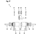
- Fig. 17 shows the cylinder adapter 3 in an exploded view.
- the cylinder adapter 3 comprises a closing element 45 with which a closing mechanism, for example a door, can be actuated.
- a closing mechanism for example a door
- the Cylinder adapter 3 further has adapter shafts 46, which are connected to the closing element 45. If one of the adapter shafts 46 is rotated, the closing element 45 is also rotated so that the closing mechanism of the door can be actuated by a rotation of the adapter shafts 46.
- a double cylinder is shown, ie the cylinder adapter 3 can be actuated from two sides.
- the cylinder adapter 3 can be actuated from two sides.
- the invention is also possible to use a half-cylinder, in which case the in Fig. 18 shown inner knob 4 is not needed.
- the adapter shaft 46 is secured by a shaft lock 49 within the cylinder adapter 3.
- the adapter shaft 46 has an outer profile, which coincides with the inner profile of the coupling shaft 12.
- torque is transferable from the clutch shaft 12 to the adapter shaft 46.
- said profiles are hexagonal profiles.
- the raster shaft 11 of the knob 1 is mounted and held within the cylinder adapter 3.
- locking elements 47 are provided in particular.
- the locking elements 47 are arranged in clip sleeves 50 and are spring-loaded by a spring 48 in the circumferential grooves 53 of the raster shaft 11 is pressed.
- the circumferential grooves 53 of the raster shaft 11 have chamfers, so that a sawtooth on the outside of the raster shaft 11 is present. In this way, the knob 1 is simply inserted into the cylinder adapter 3.
- the locking element 47 To remove the knob 1, the locking element 47 must be pulled out of the circumferential groove 53, which causes a partial removal of the cylinder adapter 3 from the door panel. Thus, a manipulation of the lock cylinder 2 according to the invention is excluded or at least difficult.
- a special tool in particular from below the cylinder adapter 3, gripped and rotated by 90 °.
- the knob 1 By providing a large number of circumferential grooves 53 within the raster shaft 11 of the knob 1 is telescopic, ie the knob 1 can used for cylinder adapter 3 with different lengths. Due to the adjustability of the knob 1, the knob can be adapted to different door thicknesses.
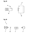
- the lock cylinder 2 additionally has an inner knob 4, which in Fig. 18 is shown.
- the inner knob 4 has an inner knob body 80, which is connected via a shaft-hub connection 81, in particular by a Scheibfeder für, with an inner shaft 82.
- the inner shaft 82 has, analogous to the coupling shaft 12, an inner profile which coincides with the outer profile of the adapter shafts 46.
- the inner shaft 82 analogous to the raster shaft 11, circumferential grooves on the outer surface.
- the inner knob 4 in the same way to the cylinder adapter 3 can be attached as the knob 1.
- the inner knob 4 always allows the actuation of the cylinder adapter 3, that is, the rotation of the closing element 45th
- Fig. 19 shows the final composition of the lock cylinder 2.
- a rotary knob 1 and an inner knob 4 is used for the actuation of the cylinder adapter 3.
- the invention also provides that for actuating the cylinder adapter 3, two rotary knob 1 can be used.
- a spacer 83 is provided in order to maintain a distance between the knob 1 and the cylinder adapter 3, finally, a spacer 83 is provided. The attachment of the raster shaft 11 of the rotary knob 1 within the cylinder adapter 3 then takes place as in relation to Fig. 17 has been described.
Landscapes
- Physics & Mathematics (AREA)
- Engineering & Computer Science (AREA)
- Manufacturing & Machinery (AREA)
- General Physics & Mathematics (AREA)
- Electromagnetism (AREA)
- Lock And Its Accessories (AREA)
Abstract
Description
- Die vorliegende Erfindung betrifft einen Drehknauf zum Betätigen eines Zylinderadapters eines Schließzylinders. Ein weiterer Aspekt der vorliegenden Erfindung betrifft einen Schließzylinder, welcher einen derartigen Drehknauf umfasst.
- Derartige Drehknäufe sind hinlänglich bekannt. Insbesondere sind mechatronische Drehknäufe bekannt, durch welche ein Zylinderadapter eines Schließzylinders von einer Türseite erst nach vorheriger Authentifizierung entriegelt werden kann. Die Authentifizierung kann beispielsweise mittels eines Chips oder einer Ausweiskarte erfolgen.
- Ohne eine derartige Authentifizierung ist der Drehknauf vom Zylinderadapter entkoppelt. Ein Drehen des Drehknaufs führt daher nicht zu einer Drehung eines Schließelements des Zylinderadapters und somit kann die Tür nicht geöffnet werden.
- Liegt jedoch über eine Authentifizierung eine Berechtigung zum Öffnen der Tür vor, wird über einen Antrieb, welcher beispielsweise ein Motor sein kann, ein Kupplungsschieber mit einem Kupplungselement formschlüssig in Eingriff gebracht werden, so dass ein an dem Drehknauf anliegendes Drehmoment über den Kupplungsschieber und das formschlüssig verbundene Kupplungselement auf das Schließelement des Zylinderadapters übertragen wird.
- Ein solcher Drehknauf ist beispielsweise aus der
WO 2014/060530 A1 bekannt. Hierbei ist eine Rasterwelle über ein Rosettenlager an einem Grundkörper des Drehknaufs gelagert. Diese Art von Lagerung benötigt allerdings zusätzliche Bauteile und ist somit nicht kosteneffizient. Weiterhin ist der Fertigungs- und Montageaufwand hoch, was auch zu hohen Kosten führen kann. - Des Weiteren sind andere Verbindungen der Rasterwelle mit dem Grundkörper des Drehknaufs bekannt. Solche Verbindungen können zum Beispiel Anschraubverbindungen oder Welle-Nabe-Verbindungen umfassen, welche aber nicht einfach und kostengünstig herzustellen sind.
- Es ist daher Aufgabe der vorliegenden Erfindung, einen Drehknauf mit einer einfachen und kostengünstigen Anordnung einer Rasterwelle in einem Drehknauf vorzuschlagen.
- Erfindungsgemäß wird diese Aufgabe gelöst durch einen Drehknauf zum Betätigen eines Zylinderadapters, umfassend:
- einen Grundkörper, und
- eine Rasterwelle,
- wobei die Rasterwelle in dem Zylinderadapter verrastbar und mit dem Grundkörper formschlüssig verbunden ist.
- Durch den erfindungsgemäßen Drehknauf ergibt sich eine Vielzahl von Vorteilen. Somit kann auf zusätzliche Bauteile verzichtet werden, wodurch eine Kostenersparnis und ein kleiner Montageaufwand ermöglicht werden. Ferner sind spezielle, teure Werkzeuge nicht nötig. Weiterhin ist durch den Formschluss eine sichere und stabile Verbindung der Rasterwelle mit dem Grundkörper des Drehknaufs sichergestellt.
- Vorzugsweise kann die Rasterwelle einen Flansch aufweisen, wobei der Flansch formschlüssig mit dem Grundkörper verbunden ist. Dadurch kann die Rasterwelle mit dem Grundkörper direkt verbunden sein, wobei die Rasterwelle einstückig ausgebildet sein kann. Ferner wird ein kompakter Aufbau bereitgestellt.
- Bevorzugt kann der Grundkörper zylinderförmig sein, wobei der Flansch eine Stirnfläche des zylinderförmigen Grundkörpers abdeckt. Somit ist der Grundkörper als Zylinder mit einem offenen Ende einfach und kostengünstig herstellbar, wobei der Flansch die Stirnseite des Grundkörpers verschließt. Dadurch wird der Grundkörper mit der Rasterwelle in kompakter Weise verbunden.
- Nach einer vorteilhaften Ausgestaltung der vorliegenden Erfindung kann der Flansch durch eine Bördelung mit dem Grundkörper verbunden sein. Dabei können einfache Werkzeuge benutzt werden, wodurch die Herstellungs- und Montagekosten niedrig gehalten werden können. Durch die Bördelung wird eine stabile und sichere Verbindung zwischen der Rasterwelle und dem Grundkörper ermöglicht. Somit wird zum einen eine ausfallsichere Funktion des Drehknaufs sichergestellt. Zum anderen kann der Drehknauf vor Manipulation geschützt werden.
- Vorteilhafterweise kann die Rasterwelle eine Vertiefung aufweisen, durch welche ein Kupplungsschieber in einem eingekuppelten Zustand beabstandet von der Rasterwelle verbleibt. Als eingekuppelter Zustand ist der Zustand zu verstehen, in welchem ein auf den Drehknauf aufgebrachtes Drehmoment zum Betätigen eines Zylinderadapters auf eine Kupplungswelle übertragen werden kann. In diesem Zustand befindet sich der Kupplungsschieber zumindest teilweise in der Vertiefung der Rasterwelle. Somit kann sichergestellt werden, dass der Kopplungsschieber im eingekuppelten Zustand mit der Rasterwelle nicht kollidiert. Dadurch wird eine ausfallsichere Funktion des Drehknaufs ermöglicht, wobei der Drehknauf kompakt ausgebildet ist.
- In vorteilhafter Weise kann die Rasterwelle mindestens einen Magneten aufweisen, der insbesondere in eine Vertiefung der Rasterwelle eingelegt ist. Dabei ist mindestens ein Magnet in einer Kupplungswelle, insbesondere in einer Vertiefung der Kupplungswelle, vorgesehen, welcher mit dem Magneten der Rasterwelle zusammenwirkt, um eine bestimmte relative Position zwischen der Rasterwelle und der Kupplungswelle sicherzustellen. Somit kann die Kupplungswelle in Bezug auf die Rasterwelle ausgerichtet sein, wodurch eine Kollision zwischen dem Kupplungsschieber und der Kupplungswelle und/oder der Rasterwelle vermieden wird.
- Nach einer bevorzugten Ausgestaltung der vorliegenden Erfindung können der Flansch und/oder der Grundkörper eine Ausrichtnase aufweisen, die in eine Ausrichtausnehmung des Grundkörpers und/oder des Flansches eingreift. Dadurch wird die Vertiefung der Rasterwelle, welche zur Aufnahme des Magneten dient, in Umfangsrichtung ausgerichtet. Dies führt zu einer sicheren und einfachen Montage der Rasterwelle am Grundkörper des Drehknaufs.
- Des Weiteren kann der Drehknauf ein Abdeckelement umfassen, wobei das Abdeckelement einen Übergang zwischen Grundkörper und Rasterwelle abdeckt. Somit ist die Verbindung zwischen dem Grundkörper und der Rasterwelle geschützt. Weiterhin kann der Grundkörper schnell hergestellt werden, ohne dass eine ausführliche Oberflächenbearbeitung von dessen Mantelfläche nötig ist, was zeit- und kostenaufwändig wäre. Über das Abdeckelement, welches auf der anderen Seite einfach herzustellen ist und je nach Anwendung angepasst werden kann, ist ein optisch hochwertiger Eindruck möglich.
- Ferner bevorzugt kann die Rasterwelle eine Hohlwelle sein, wobei innerhalb der Rasterwelle die Kupplungswelle gelagert ist, über die ein Schließelement des Zylinderadapters betätigbar ist. Somit ist der Drehknauf insgesamt kompakt ausgebildet. Dies führt zu einem optisch eleganten Eindruck des Drehknaufs sowie zu einem kleineren Gewicht, wodurch das Betätigen des Drehknaufs erleichtert wird.
- Weiter bevorzugt kann durch die Rasterwelle, insbesondere durch den Flansch, eine Platine, insbesondere ein erstes Platinenteil, axial, insbesondere über einen Haltering, fixiert sein. Somit ist die Platine, welche elektrische Komponenten aufweisen kann, durch eine einfach herstellbare konstruktive Maßnahme umlaufend am Rand in Position gehalten.
- Das erste Platinenteil der Platine kann bevorzugt flexibel mit einem zweiten Platinenteil verbunden sein, wobei das erste Platinenteil und das zweite Platinenteil einen Antrieb und ein Batteriefach umschließen, wobei insbesondere der Antrieb quer zum Batteriefach gelagert ist. Durch die flexible Verbindung zwischen den beiden Platinenteilen ist die Montage der unterschiedlichen Bauteile in den Drehknauf vereinfacht, indem die Platine als vormontierte Baugruppe an die Anordnung der vorhandenen Bauteile angepasst werden kann. Die Platine ist vorzugsweise als eine Starr-Flex-Platine ausgebildet, wobei das erste und das zweite Platinenteil starr ausgebildet sind. Somit weist die Platine eine strukturelle Integrität sowie eine Flexibilität auf.
- Um die Rasterwelle axial zu fixieren, kann vorzugsweise an einer Innenseite einer Mantelfläche des Grundkörpers ein Absatz vorgesehen sein. Somit ist es möglich, ohne weitere Bauteile die axiale Fixierung der Rasterwelle bereitzustellen.
- Ein weiterer Aspekt der vorliegenden Erfindung betrifft einen Schließzylinder, welcher einen erfindungsgemäßen Drehknauf sowie einen Zylinderadapter umfasst, wobei die Rasterwelle formschlüssig innerhalb des Zylinderadapters befestigt und rotierbar innerhalb des Zylinderadapters gelagert ist. Somit ist die Rasterwelle am dem Zylinderadapter zugewandten Ende einfach und sicher gelagert.
- Weiter bevorzugt kann die Rasterwelle zumindest eine umlaufende Nut aufweisen, in die ein, insbesondere federbelastetes, Rastelement und/oder eine Wellensicherung des Zylinderadapters eingreift und insbesondere eine axiale Verschiebung der Rasterwelle verhindert. Somit wird eine axiale Position der Rasterwelle definiert. Durch die Federbelastung wird die Rasterwelle ständig mit einer Kraft des Rastelements gedrückt, was zu einer noch sicheren Anordnung der Rasterwelle im Zylinderadapter führt.
- Ferner bevorzugt kann der Schließzylinder ein Schließelement umfassen, das von zumindest einer Adapterwelle betätigbar ist, wobei die Adapterwelle wahlweise von dem Drehknauf betätigbar oder freilaufend ist. Durch die Adapterwelle kann ein auf den Drehknauf aufgebrachtes Drehmoment in einem eingekuppelten Zustand eines Kupplungsschiebers auf das Schließelement übertragen werden. Somit wird der Schließzylinder entriegelt und die Tür geöffnet.
- In den folgenden Absätzen sind wesentliche Aspekte der vorliegenden Erfindung dargestellt. Diese Aspekte können natürlich in Alleinstellung oder beliebigen Kombinationen mit den vorgenannten erfinderischen Merkmalen umgesetzt werden:
- Bevorzugt umfasst der Drehknauf zum Betätigen eines Zylinderadapters einen Grundkörper mit einer ersten Halterung, einen Antrieb, einen Kupplungsschieber, welcher vom Antrieb antreibbar ist, um den Drehknauf von einem entkoppelten Zustand in einen gekoppelten Zustand zum Betätigen des Zylinderadapters zu bringen, und eine Antriebstasche, in welcher der Antrieb angeordnet ist, und welche in die erste Halterung einschiebbar ist.
- Bevorzugt ist der Grundkörper zumindest teilweise hohlzylinderförmig ausgebildet und weist eine Mantelfläche auf, wobei die erste Halterung an einer Innenseite der Mantelfläche angeordnet.
- Bevorzugt weist die Antriebstasche eine zu einer Form der ersten Halterung im Wesentlichen komplementären Form auf, wobei insbesondere die erste Halterung rotationsasymmetrisch ausgebildet.
- Bevorzugt umfasst der Drehknauf eine zweite Halterung, in welcher der Kupplungsschieber gleichzeitig mit der Antriebstasche einschiebbar ist, wobei insbesondere die zweite Halterung an der Innenseite der Mantelfläche vorgesehen ist.
- Bevorzugt ist der Kupplungsschieber in der zweiten Halterung verschiebbar in Richtung einer Längsachse des Grundkörpers.
- Bevorzugt weist die Antriebstasche einen Antriebssteckverbinderhalter auf, in welchem ein Antriebsteckverbinder, insbesondere mit Spiel, angeordnet ist, um eine elektrische Kontaktierung zwischen dem Antrieb und mindestens einer elektrischen Komponente des Drehknaufs bereitzustellen.
- Bevorzugt ist ein Antriebsgegensteckverbinder auf einer Platine, insbesondere einem ersten Platinenteil, angeordnet, wobei der Antriebsgegensteckverbinder mit dem Antriebssteckverbinder zusammenwirkt.
- Bevorzugt ist das erste Platinenteil in Bezug auf den Zylinderadapter vor dem Antrieb angeordnet, wobei insbesondere das erste Platinenteil teilweise unter dem Kupplungsschieber angeordnet ist.
- Bevorzugt weist das erste Platinenteil eine Ausnehmung auf, durch welche der Kupplungsschieber zumindest teilweise bewegbar ist und/oder in welcher die zweite Halterung zumindest teilweise angeordnet ist, wobei insbesondere das erste Platinenteil radial festgelegt ist.
- Bevorzugt weist die Antriebstasche einen Kabelkanal auf, in welchem ein Kabel zum elektrischen Kontaktieren des Antriebs mit dem Antriebssteckverbinder verläuft.
- Bevorzugt weist die Antriebstasche einen Antriebstaschenanschlag auf, welcher das Einschieben der Antriebstasche in die erste Halterung begrenzt.
- Bevorzugt weist die Antriebstasche mindestens eine Clipsnase auf, über welche die Antriebstasche mit der Halterung verrastbar ist.
- Bevorzugt ist die erste Halterung als eine Durchgangsöffnung oder eine Sacköffnung in dem Grundkörper ausgebildet.
- Bevorzugt ist ein zweites Platinenteil in Bezug auf den Zylinderadapter hinter dem Antrieb angeordnet und die erste Halterung bedeckt, wobei insbesondere der Grundkörper einen Absatz aufweist, so dass das zweite Platinenteil beabstandet von der ersten Halterung gelagert ist.
- Bevorzugt umfasst der Schließzylinder einen erfindungsgemäßen Drehknauf und einen Zylinderadapter, welcher vom Drehknauf betätigbar ist, wobei die Antriebstasche in der ersten Halterung eingeschoben ist.
- Bevorzugt umfasst der Drehknauf zum Betätigen eines Zylinderadapters einen Grundkörper mit einer Batterieausnehmung, und ein Batteriefach zum Aufnehmen einer Batterie, wobei das Batteriefach in die Batterieausnehmung einschiebbar ist.
- Bevorzugt weist das Batteriefach einen im Wesentlichen C-förmigen Querschnitt auf.
- Bevorzugt weist der Grundkörper eine Mantelfläche auf, zu welcher die Batterieausnehmung senkrecht ausgebildet ist.
- Bevorzugt weist der Grundkörper eine erste Mantelöffnung und eine zweite Mantelöffnung auf, wobei sich die Batterieausnehmung von der ersten Mantelöffnung bis zur zweiten Mantelöffnung erstreckt, wobei insbesondere das Batteriefach ausschließlich über die erste Mantelöffnung einschiebbar ist.
- Bevorzugt weist das Batteriefach einen Batteriefachanschlag auf, welcher an einem Grundkörperanschlag anliegt, wenn das Batteriefach vollständig in die Batterieausnehmung eingeschoben ist.
- Bevorzugt weist das Batteriefach einen Batteriesteckverbinder auf, welcher in einen Batteriegegensteckverbinder des Grundkörpers zum elektrischen Kontaktieren der Batterie mit mindestens einer elektrischen Komponente des Grundkörpers einsteckbar ist.
- Bevorzugt umfasst der Batteriesteckverbinder ein Kabel, welches mit Batteriekontakten des Batteriefachs oder direkt mit der Batterie elektrisch verbunden ist, insbesondere an Batteriekontakten des Batteriefachs oder direkt an der Batterie angelötet ist.
- Bevorzugt umfasst der Schließzylinder einen erfindungsgemäßen Drehknauf und einen Zylinderadapter, welcher vom Drehknauf betätigbar ist.
- Bevorzugt wird ein Verfahren zum Einsetzen einer Batterie in einen Drehknauf zum Betätigen eines Zylinderadapters vorgeschlagen, wobei der Drehknauf einen Grundkörper mit einer Batterieausnehmung und ein Batteriefach aufweist, umfassend die Schritte des Einsetzens der Batterie in das Batteriefach, des elektrischen Kontaktierens der Batterie mit dem Batteriefach, und des Einschiebens des Batteriefachs in die Batterieausnehmung.
- Bevorzugt wird das Batteriefach durch eine im Grundkörper ausgebildete erste Mantelöffnung in die Batterieausnehmung eingeschoben.
- Bevorzugt wird das Batteriefach bis zu einem im Grundkörper ausgebildeten Grundkörperanschlag eingeschoben.
- Bevorzugt wird die Batterie gleichzeitig in das Batteriefach eingesetzt und mit dem Batteriefach elektrisch kontaktiert.
- Bevorzugt wird das Batteriefach gleichzeitig eingeschoben und mit elektrischen Komponenten des Grundkörpers kontaktiert.
- Bevorzugt wird ein Verfahren zum Entfernen einer Batterie von einem Drehknauf zum Betätigen eines Zylinderadapters vorgeschlagen, wobei der Drehknauf einen Grundkörper mit einer Batterieausnehmung und ein Batteriefach aufweist, in welchem eine Batterie aufgenommen ist, und welches in der eingeschoben ist, umfassend die Schritte des Entfernens des Batteriefachs aus der Batterieausnehmung, des Lösens einer elektrischen Kontaktierung des Batteriefachs mit der Batterie, und des Entfernens der Batterie vom Batteriefach.
- Bevorzugt wird ein Verfahren zum Entfernen einer Batterie vorgeschlagen, wobei das Batteriefach federbelastet ist und der Grundkörper eine Mantelöffnung aufweist, umfassend die Schritte des Lösens einer Verriegelung zwischen dem Batteriefach und dem Grundkörper, und des Entfernens des Batteriefachs durch die Federbelastung über die erste Mantelöffnung.
- Bevorzugt wird ein Verfahren zum Entfernen einer Batterie vorgeschlagen, wobei der Grundkörper eine erste Mantelöffnung und eine zweite Mantelöffnung aufweist, umfassend die Schritte des Lösens einer Verriegelung zwischen dem Batteriefach und dem Grundkörper, des Aufbringens einer Kraft auf das Batteriefach durch die zweite Mantelöffnung, und des Entfernens des Batteriefachs über die erste Mantelöffnung.
- Bevorzugt umfasst der Drehknauf zum Betätigen eines Zylinderadapters einen Grundkörper, und ein Abdeckelement, das den Grundkörper zumindest teilweise umgibt, wobei das Abdeckelement zumindest eine Umfangsöffnung aufweist, und wobei die Umfangsöffnung Zugriff auf eine Mantelfläche des Grundkörpers erlaubt.
- Bevorzugt weist der Grundkörper zumindest eine Batterieausnehmung auf, wobei die Batterieausnehmung durch die Umfangsöffnung des Abdeckelements erreichbar ist.
- Bevorzugt ist der Grundkörper zumindest teilweise von einer abnehmbaren Knaufkappe umgeben, wobei die Umfangsöffnung des Abdeckelements durch die Knaufkappe abgedeckt werden kann.
- Bevorzugt weist die Knaufkappe eine umlaufende Dichtung auf, die an dem Abdeckelement anliegt.
- Bevorzugt umschließen die Knaufkappe und das Abdeckelement die Mantelfläche des Grundkörpers vollständig.
- Bevorzugt weist der Grundkörper eine erste Stirnfläche auf, an der eine Rasterwelle angeordnet ist, über die der Drehknauf an dem Zylinderadapter anbringbar ist, wobei das Abdeckelement eine Stirnöffnung zur Durchführung der Rasterwelle aufweist.
- Bevorzugt weist die Knaufkappe einen Leuchtring auf, der insbesondere in die Knaufkappe eingeklebt und/oder eingeclipst ist.
- Bevorzugt sind die Knaufkappe und das Abdeckelement über ein gemeinsames Montageelement an der Mantelfläche des Grundkörpers befestigbar.
- Bevorzugt ist das Abdeckelement auf dem Grundkörper aufgepresst und/oder die Knaufkappe weist auf einer Innenseite der Knaufkappe ein erstes Verbindungselement zum Verbinden mit dem Grundkörper auf, wobei das erste Verbindungselement als mindestens eine, bevorzugt mindestens zwei Rastnasen ausgebildet ist, wobei insbesondere der Grundkörper und/oder ein Batteriefach ein zweites Verbindungselement, insbesondere eine Ausnehmung, bevorzugt mindestens zwei Ausnehmungen, zum Verbinden mit dem ersten Verbindungselement aufweist.
- Bevorzugt ist die Knaufkappe aus einem nicht leitenden Material, insbesondere Kunststoff, hergestellt, wobei die Knaufkappe den Grundkörper und das Abdeckelement mit einem ersten Kappenteil, insbesondere mit dem Leuchtring, überragt, wobei insbesondere eine Antenne in dem ersten Kappenteil angeordnet ist.
- Bevorzugt weist der Grundkörper an der Mantelfläche eine Kontur auf, die die Knaufkappe radial fixiert.
- Bevorzugt weist der Grundkörper an der Mantelfläche eine Ausnehmung auf, in welcher zumindest eine elektrische Leitung, bevorzugt eine flexible Verbindung zwischen Platinenteilen, geführt ist, wobei das Abdeckelement die Ausnehmung überdeckt.
- Bevorzugt sind beim Abdeckelement zwei gegenüberliegende Umfangsöffnungen vorgesehen, wobei insbesondere die jeweils eine erste Mantelöffnung der Batterieausnehmung und eine zweite Mantelöffnung der Batterieausnehmung vollständig unter den Umfangsöffnungen liegen.
- Bevorzugt ist auf der Innenseite der Knaufkappe ein Absatz vorgesehen, mit der die Knaufkappe an einer zweiten Stirnfläche des Grundkörpers anliegt.
- Bevorzugt umfasst der Schließzylinder einen erfindungsgemäßen Drehknauf sowie einen Zylinderadapter, der von dem Drehknauf betätigbar ist.
- Die Erfindung wird nun anhand eines Ausführungsbeispiels unter Berücksichtigung der beigefügten Zeichnung näher beschrieben. Dabei zeigen:
- Fig. 1
- eine schematische Explosionsdarstellung des Schließzylinders gemäß einem Ausführungsbeispiel der Erfindung,
- Fig. 2
- eine schematische Darstellung einer Kuppeleinheit des Schließzylinders gemäß dem Ausführungsbeispiel der Erfindung,
- Fig. 3
- eine schematische Darstellung eines Teilbereichs der Kuppeleinheit des Schließzylinders gemäß dem Ausführungsbeispiel der Erfindung,
- Fig. 4
- eine schematische Darstellung eines Teilbereichs des Drehknaufs des Schließzylinders gemäß dem Ausführungsbeispiel der Erfindung,
- Fig. 5
- eine schematische Darstellung eines weiteren Teilbereichs des Drehknaufs des Schließzylinders gemäß dem Ausführungsbeispiel der Erfindung,
- Fig. 6
- eine andere schematische Darstellung des weiteren Teilbereichs des Drehknaufs des Schließzylinders gemäß dem Ausführungsbeispiel der Erfindung,
- Fig. 7
- einen weiteren anderen Teilbereich des Drehknaufs des Schließzylinders gemäß dem Ausführungsbeispiel der Erfindung,
- Fig. 8
- eine schematische Darstellung eines Verbindungsbereichs des Drehknaufs des Schließzylinders gemäß dem Ausführungsbeispiel der Erfindung,
- Fig. 9
- eine schematische Explosionsdarstellung der Teilbereiche des Drehknaufs aus
Fig. 7 undFig. 8 , - Fig. 10
- eine schematische Darstellung der Teilbereiche des Drehknaufs aus
Fig. 7 undFig. 8 , - Fig. 11
- eine schematische Schnittdarstellung aus
Fig. 10 , - Fig. 12
- eine schematische Darstellung der Stromversorgung des Drehknaufs des Schließzylinders gemäß dem Ausführungsbeispiel der Erfindung,
- Fig. 13
- eine schematische Darstellung des Drehknaufs des Schließzylinders gemäß dem Ausführungsbeispiel der Erfindung zusammen mit der Stromversorgung aus
Fig. 12 , - Fig. 14
- eine schematische Darstellung einer Verkleidung des Drehknaufs des Schließzylinders gemäß dem Ausführungsbeispiel der Erfindung,
- Fig. 15
- eine schematische Darstellung einer weiteren Verkleidung des Drehknaufs des Schließzylinders gemäß dem Ausführungsbeispiel der Erfindung,
- Fig. 16
- eine Kombination der
Fig. 14 und15 , - Fig. 17
- eine schematische Darstellung des Zylinderadapters des Schließzylinders gemäß dem Ausführungsbeispiel der Erfindung,
- Fig. 18
- eine schematische Darstellung eines Innenknaufs des Schließzylinders gemäß dem Ausführungsbeispiel der Erfindung,
- Fig. 19
- eine Explosionsdarstellung des Schließzylinders gemäß einem Ausführungsbeispiel der Erfindung.
-
Fig. 1 zeigt schematisch eine Explosionsdarstellung des Schließzylinders 2 mit sämtlichen Baukomponenten. Die Zusammenführung der einzelnen Baukomponenten zu dem erfindungsgemäßen Schließzylinder 2 wird in den nachfolgenden Figuren beschrieben. - Der Schließzylinder 2 umfasst drei Komponenten: einen Drehknauf 1, einen Zylinderadapter 3 und einen Innenknauf 4. Sowohl über den Drehknauf 1 als auch über den Innenknauf 4 ist der Zylinderadapter 3 betätigbar, sodass insbesondere eine mit dem Schließzylinder 2 ausgestattete Tür freigebbar ist. Dabei ist erfindungsgemäß vorgesehen, dass der Zylinderadapter 3 über den Innenknauf 4 stets ansteuerbar ist, während der Drehknauf 1 von einer Kuppeleinheit 65 von dem Zylinderadapter 3 entkoppelbar ist, sodass der Drehknauf 1 frei rotierbar ist. Der Aufbau der Kuppeleinheit 65 ist in
Fig. 2 gezeigt. -
Fig. 2 zeigt eine Explosionsdarstellung der Kuppeleinheit 65. Die Kuppeleinheit 65 umfasst eine Antriebstasche 14, in der ein Antrieb 15 aufgenommen ist. Der Antrieb 15 ist mit einer Gewindespindel 17 verbunden, sodass die Gewindespindel 17 von dem Antrieb 15 rotierbar ist. Auf der Gewindespindel 17 ist ein Mitnehmer 18 angeordnet, sodass durch eine Rotation der Gewindespindel 17 durch den Antrieb 15 der Mitnehmer 18 axial auf der Gewindespindel 17 verschoben wird, wenn der Mitnehmer 18 rotationsfest gehalten wird. Zum rotationsfesten Halten ist der Mitnehmer 18 in einer ersten Kupplungsschieberausnehmung 27 eines Kupplungsschiebers 16 angeordnet. Der Kupplungsschieber 16 ist wiederum, wie inFig. 4 gezeigt ist, an einem Grundkörper 5 des Drehknaufs 1 gelagert, sodass lediglich eine axiale Verschiebung des Kupplungsschiebers 16 und damit des Mitnehmers 18 ermöglicht ist. Insbesondere eine Rotation des Kupplungsschiebers 16 und damit des Mitnehmers 18 ist somit verhindert. Auf diese Weise ist der Kupplungsschieber 16 durch den Antrieb 15 bewegbar, indem eine Rotation des Antriebs 15 eine Rotation der Gewindespindel 17 bewirkt, wodurch der Mitnehmer 18 auf der Gewindespindel 17 verschoben wird, was sich aufgrund der Anordnung des Mitnehmers 18 in der ersten Kupplungsschieberausnehmung 27 auf den Kupplungsschieber 16 auswirkt. Somit ist der Kupplungsschieber 16 parallel zu einer Welle des Antriebs 15 und damit parallel zu der Gewindespindel 17 bewegbar. - Der Kupplungsschieber 16 weist ein Eingriffselement 29 auf. Die Funktion des Eingriffselements 29 wird mit Bezug auf
Fig. 9 beschrieben. Weiterhin kann der Kupplungsschieber 16 vorteilhafterweise eine zweite Kupplungsschieberausnehmung 28 aufweisen, wodurch der Kupplungsschieber 16 ein sehr geringes Gewicht aufweist. Somit ist der Kupplungsschieber 16 einfach und schnell beschleunigbar, sodass kurze Verschiebzeiten gewährleistet sind. - Der Antrieb 15 ist innerhalb der Antriebstasche 14 angeordnet. Dabei ist außerdem vorgesehen, dass ein Kabel zur Versorgung des Antriebs 15 mit elektrischer Energie in einem Kabelkanal (nicht gezeigt) der Motortasche 14 geführt ist. Das Kabel des Antriebs 15 wird unter dem Antrieb 15 oder seitlich der Antriebstasche 14 eingefädelt und endet in enem Antriebssteckverbinder 19. Zum Kontaktieren des Antriebs 15 weist die Motortasche 14 einen Antriebssteckverbinderhalter 26 auf. In dem Antriebssteckverbinderhalter 26 ist der Antriebssteckverbinder 19 angeordnet, insbesondere von unten eingesetzt, wobei der Antriebssteckverbinder 19 als ein Antriebstecker ausgebildet und mit dem Kabel verbunden ist. Somit ist der Antrieb 15 über den Antriebssteckverbinder 19 elektrisch kontaktierbar und damit ansteuerbar. Zum Kontaktieren des Antriebssteckverbinders 19 ist außerdem bevorzugt vorgesehen, dass der Antriebssteckverbinder 19 spielbehaftet innerhalb des Antriebssteckverbinderhalters 26 der Motortasche 14 angeordnet ist. Das elektrische Kontaktieren des Antriebssteckverbinders 19 ist in den
Fig. 5 und6 gezeigt. -
Fig. 3 zeigt den Antrieb 15 mit der Gewindespindel 17. Der Antrieb 15 ist bevorzugt ein Gleichstrommotor und weist vorteilhafterweise einen Durchmesser von 6 mm auf. Die Gewindespindel 17 ist auf einer Welle des Antriebs 15 angebracht, wobei ein Abstand 200 zwischen einem Gehäuse des Antriebs 15 und der Gewindespindel 17 vorteilhafterweise 0,3 mm bis 0,5 mm beträgt. Die Gewindespindel 17 ist insbesondere eine M2-Gewindespindel. - Die Kuppeleinheit 65 ist in den Grundkörper 5 des Drehknaufs 1 einschiebbar. Dazu weist der Grundkörper 5, welcher insebesondere bevorzugt aus Metall ausgebildet ist, eine erste Halterung 21 sowie eine zweite Halterung 22 auf. Die erste Halterung 21 dient zur Aufnahme der Antriebstasche 14, während die zweite Halterung 22 zur Aufnahme des Kupplungsschiebers 16 dient. Zum Fixieren der Kuppeleinheit 65 innerhalb des Grundkörpers 5 weist die Antriebstasche 14 außerdem einen Antriebsanschlag 25 auf, der nach dem Einschieben der Antriebstasche 14 in die erste Halterung 21 an dem Grundkörper 5 anliegt. Außerdem ist vorgesehen, dass in dieser Position Clipsnasen 24 der Antriebstasche 14 die erste Halterung 21 umgreifen, sodass eine formschlüssige Verbindung zwischen der ersten Halterung 21 des Grundkörpers 5 und der Antriebstasche 14 der Kuppeleinheit 65 vorhanden ist. Somit ist die Kuppeleinheit 65 fest und sicher in dem Grundkörper 5 arretiert.
- Der Kupplungsschieber 16 ist innerhalb der zweiten Halterung 22 angeordnet. Innerhalb der zweiten Halterung 22 ist der Kupplungsschieber 16 longitudinal verschiebbar, d. h. parallel zu einer Längsachse 100 des Grundkörpers 5. Insbesondere ist vorgesehen, dass die Längsachse 100 parallel zu der Welle des Antriebs 15 angeordnet ist. Andere Bewegungen des Kupplungsschiebers 16, insbesondere eine Rotation des Kupplungsschiebers 16, sind durch die zweite Halterung 22 verhindert.
- Der Grundkörper 5 weist insbesondere einen Durchmesser von 40 mm auf. Dabei ist der Grundkörper 5 vorteilhafterweise hohlzylinderförmig ausgebildet, wobei der zylinderförmige Grundkörper 5 eine Mantelfläche 20 aufweist. An einer Innenseite der Mantelfläche 20 ist die zweite Halterung 22 angebracht, wobei die erste Halterung 21 relativ zu der zweiten Halterung 22 radial innerhalb angeordnet ist. Durch die Anbringung der zweiten Halterung 22 unmittelbar an der Mantelfläche 20 ist ein größtmöglicher radialer Abstand zwischen dem Eingriffselement 29 und der Längsachse 100 erreicht. Somit muss das Eingriffselement 29 geringe Kräfte übertragen, was mit Bezug auf
Fig. 9 erklärt wird. - Der Grundkörper 5 weist außerdem eine Batterieausnehmung 23 auf, die durch eine erste Mantelöffnung 54 gebildet ist. Die Funktionalität der Batterieausnehmung 23 wird mit Bezug auf
Fig. 13 erklärt. - Die erste Halterung 21 und/oder die zweite Halterung 22 können als axiale Durchgangsöffnung des Grundkörpers 5 ausgebildet sein. Vorteilhafterweise ist jedoch vorgesehen, dass sowohl die erste Halterung 21 als auch die zweite Halterung 22 keine Durchgangsöffnungen sind. Auf diese Weise sind die erste Halterung 21 und die zweite Halterung 22 lediglich von einer Seite axial erreichbar. Von der axial gegenüberliegenden Seite ist ein Erreichen der ersten Halterung 21 und/oder der zweiten Halterung 22 somit nicht möglich. Dabei ist insbesondere vorgesehen, dass diese Seite diejenige Seite ist, die von dem Zylinderadapter 3 weg weist. Somit ist eine Manipulation der Kuppeleinheit 65 und damit des Drehknaufs 1 verhinderbar.
- Die
Fig. 5 und6 zeigen eine Platine 10, die innerhalb des Drehknaufs 1 angeordnet ist. Dabei ist vorgesehen, dass ein erstes Platinenteil 57 von einer ersten Stirnfläche 51 des Grundkörpers 5 (vgl.Fig. 7 ) an dem Grundkörper 5 befestigt wird, während ein zweites Platinenteil 61 von einer zweiten Stirnfläche 52 (vgl.Fig. 7 ) des Grundkörpers 5 an dem Grundkörper 5 befestigt wird. Zwischen dem ersten Platinenteil 57 und dem zweiten Platinenteil 61 ist ein Verbindungsteil 66 angeordnet. Das Verbindungsteil 66 dient zum mechanischen und elektrischen Verbinden des ersten Platinenteils 57 mit dem zweiten Platinenteil 61. Das Verbindungsteil 66 ist in diesem Ausführungsbeispiel vollständig flexibel ausgebildet. Alternativ kann das Verbindungsteil 66 alternativ auch einen starren Anteil aufweisen. Das erste Platinenteil 57 und/oder das zweite Platinenteil 61 sind bevorzugt starr ausgebildet. - Das erste Platinenteil 57 umfasst insbesondere eine Ansteuerung und/oder eine Regelung des Antriebs 15. Daher weist das erste Platinenteil 57 einen Antriebsgegensteckverbinder 56 auf, der als eine Kontaktbuchse ausgebildet und mit dem Antriebssteckverbinder 19 elektrisch verbindbar ist. Wird das erste Platinenteil 57 an dem Grundkörper 5 befestigt, so ist vorgesehen, dass eine Kontaktierung von Antriebssteckverbinder 19 und Antriebsgegensteckverbinder 56 zwangsläufig stattfindet. Um dies zu erreichen weist das erste Platinenteil 57 eine Ausnehmung 58 und eine Mittelbohrung 67 auf. Die Ausnehmung 58 dient zum Durchführen der ersten Halterung 21 sowie der zweiten Halterung 22 des Grundkörpers 5 durch das erste Platinenteil 57. Gleichzeitig ist das erste Platinenteil 57 rotationsfest innerhalb des Grundkörpers 5 gehalten. Durch die Mittelbohrung 67 ist sichergestellt, dass das erste Platinenteil 57 mittig in dem Grundkörper 5 angeordnet ist, indem ein Positionierdom 68 des Grundkörpers 5 (vgl.
Fig. 7 ) durch die Mittelbohrung 67 des ersten Platinenteils 57 geführt ist. Weiterhin weist das erste Platinenteil 57 einen Batteriegegensteckverbinder 41 auf, die von einem Batteriefach 8 kontaktierbar ist (vgl.Fig. 13 ). Somit ist insbesondere vorgesehen, dass das erste Platinenteil 57 sämtliche elektrischen Komponenten umfasst, die zum Betreiben und Ansteuern des Antriebs 15 notwendig sind. Dahingegen weist das zweite Platinenteil 61 sämtliche elektrischen Komponenten auf, die für eine kabellose Datenübertragung benötigt werden. So ist insbesondere vorgesehen, dass das zweite Platinenteil 61 kabellos mit Codekarten kommunizieren kann, welche anzeigen, ob eine Berechtigung zum Betätigen des Zylinderadapters 3 vorliegt oder nicht. Über das Verbindungsteil 66 kann das Empfangen einer derartigen Berechtigung durch das zweiten Platinenteil 61 an das erste Platinenteil 57 übertragen werden, sodass das erste Platinenteil 57 die Kuppeleinheit 65, insbesondere den Antrieb 15, derart ansteuert, dass der Drehknauf 1 an den Zylinderadapter 3 angekoppelt ist. Dies wird durch ein Verschieben des Kupplungsschiebers 16 bewirkt. - Um festzustellen, in welcher Position sich der Kupplungsschieber 16 befindet, weist das erste Platinenteil 57 außerdem einen ersten Sensor 69 sowie einen zweiten Sensor 70 auf, wobei der erste Sensor 69 und der zweite Sensor 70 auf unterschiedlichen Seiten des ersten Platinenteils 57 angeordnet sind. Insbesondere sind der erste Sensor 69 und/oder der zweite Sensor 70 eine Lichtschranke. Die Lichtschranke ist von einem Steg 71 des Kupplungsschiebers 16 unterbrechbar, wobei je nach Position des Kupplungsschiebers 16 die Lichtschranke des ersten Sensors 69 oder die Lichtschranke des zweiten Sensors 70 unterbrochen ist. Somit ist feststellbar, wo sich der Steg 71 und damit der Kupplungsschieber 16 befindet. Insbesondere ist auf diese Weise unterscheidbar, ob sich der Kupplungsschieber 16 in einer eingekoppelten Position oder in einer ausgekoppelten Position befindet. Ein Unterschied zwischen der eingekoppelten Position und der ausgekoppelten Position wird mit Bezug auf die
Fig. 8 und9 erklärt. -
Fig. 7 zeigt den Grundkörper 5 des Drehknaufs 1 mit eingesetzter Platine 10. Das Verbindungsteil 66 ist dabei in einer Ausnehmung 64 des Grundkörpers geführt. - Das erste Platinenteil 57 wird über einen Haltering 13 innerhalb des Grundkörpers 5 gehalten. Die Befestigung des Halterings 13 wird mit Bezug auf
Fig. 9 erklärt. Zum Fixieren des zweiten Platinenteils 61 an der zweiten Stirnfläche 52 des Grundkörpers 5 sind zwei Befestigungsmittel 72 vorgesehen, die durch Öffnungen des zweiten Platinenteils 61 greifen. Die Befestigungsmittel 72 sind insbesondere Schrauben, bevorzugt M2x4 Linsenkopfschrauben. - Die
Fig. 8 bis 11 beschreiben die Verbindung des Grundkörpers 5 mit einer Rasterwelle 11.Fig. 8 zeigt die Rasterwelle 11 sowie eine Kupplungswelle 12. Die Rasterwelle 11 umfasst einen hülsenförmigen Bereich, der an seiner Außenseite eine Vielzahl von umlaufenden Nuten 53 aufweist. Über die umlaufenden Nuten 53 ist die Rasterwelle 11 innerhalb des Zylinderadapters 3 befestigbar. Das Innere des hülsenförmigen Bereichs bildet eine Aussparung 59 für die Kupplungswelle 12. Somit ist die Kupplungswelle 12 innerhalb der Rasterwelle 11 angeordnet. Ferner ist die Kupplungswelle 12 auf einer Seite durch den Positionierdom 68 des Grundkörpers 5 (vgl.Fig. 7 ) und auf der anderen Seite durch einen Anschlag 84, welcher an einem Flansch 34 der Rasterwelle 11 anliegt, axial fixiert. - Weiterhin ist die Rasterwelle 11 über den Flansch 34 die Rasterwelle 11 mit dem Grundkörper 5 verbindbar. Der Flansch 34 weist außerdem Magnetausnehmungen 73 auf, in denen Magnete 60, insbesondere Neodym-Magnete, einsetzbar, insbesondere einklebbar, sind. Die Magnete 60 sind bevorzugt bündig mit dem Flansch 34. Ebenso sind an der Kupplungswelle 12, insbesondere an einem Flansch der Kupplungswelle 12, insbesondere in Flanschausnehmungen der Kupplungswelle 12, Magnete 60 angeordnet. Bevorzugt sind die Magnete 60 in die Kupplungswelle 12 eingeklebt. Mit den Magneten ist verhinderbar, dass der Mitnehmer 18, insbesondere das Eingriffselement 29, mit der Kupplungswelle 12 kollidiert.
- Zum Einkuppeln weist die Kupplungswelle 12 mindestens eine Kupplungsnase 74 auf. In
Fig. 8 ist eine Kupplungswelle 12 mit zwei Kupplungsnasen 74 gezeigt. - Über das Eingriffselement 29 des Kupplungsschiebers 16 ist die Kupplungswelle 12 an eine Rotation des Grundkörpers 5 ankoppelbar oder von einer Rotation des Grundkörpers 5 trennbar. Befindet sich der Kupplungsschieber 16 in einer eingekoppelten Position, d. h. in einer Position in der der Mitnehmer 18 auf der Gewindespindel 17 einen maximalen Abstand zu dem Antrieb 15 aufweist, so ist ein Drehmoment von dem Grundkörper 5 über den Kupplungsschieber 16 auf die Kupplungsnase 74 und somit auf die Kupplungswelle 12 übertragbar. In dieser Position stellt eine Vertiefung 79 der Rasterwelle 11, insbesondere des Flansches 34 der Rasterwelle 11, sicher, dass der Kupplungsschieber 16, insbesondere das Eingriffselement 29, nicht mit dem Flansch 34 der Rasterwelle 11 kollidiert. Durch die Vertiefung 79 ist somit stets ein Abstand zwischen Flansch 34 und Eingriffselement 29 sichergestellt, selbst wenn sich der Kupplungsschieber 16 in der eingekuppelten Position befindet. Befindet sich der Kupplungsschieber 16 jedoch in einer ausgekuppelten Position, d. h. in einer Position in der der Mitnehmer 18 einen minimalen Abstand zu dem Antrieb 15 aufweist, so ist kein Drehmoment von dem Grundkörper 5 auf die Kupplungswelle 12 übertragbar.
- Die Magnete 60 verhindern ein Kollidieren des Kupplungsschiebers 16, insbesondere des Eingriffselements 29 mit den Kupplungsnasen 74, indem durch eine abstoßende Wirkung der Magnete 60 der Kupplungswelle 12 und der Rasterwelle 11 verhindert wird, dass die Kupplungswelle 12 in einer Position verharrt, bei der die Kupplungsnasen 74 unmittelbar vor dem Kupplungsschieber 16 angeordnet sind. Somit ist besagte Kollision zwischen Kupplungsschieber 16 und Kupplungsnasen 74 vermeidbar. Die Magnete sind vorteilhafterweise Scheibenmagnete mit einer Abmessung von 4x1 mm oder 3x1,5 mm.
- Die Kupplungswelle 12 ist insbesondere ebenfalls hohl ausgebildet und weist ein Innenprofil auf, mit dem eine Adapterwelle 46 (vgl.
Fig. 17 ) des Zylinderadapters 3 bewegbar ist. Zur Abdeckung der Kupplungswelle 12 zu dem Drehknauf 1 hin ist vorgesehen, dass eine Wellenscheibe 75 in die hohle Kupplungswelle 12 eingepresst ist. Insbesondere liegt der Positionierdom 68 an der Wellenscheibe 75 an, um die Kupplungswelle 12 axial zu fixieren. -
Fig. 9 zeigt eine Kombination ausFig. 7 undFig. 8 . Somit zeigtFig. 9 , wie die Rasterwelle 11 und die Kupplungswelle 12 mit dem Grundkörper 5 verbindbar sind. - Zum Ausrichten der Rasterwelle 11 bezüglich des Grundkörpers 5 weist der Flansch 34 der Rasterwelle 11 eine Ausrichtausnehmung 33 auf, während der Grundkörper 5 eine Ausrichtnase 32 aufweist. Wird die Rasterwelle 11 mit dem Grundkörper 5 verbunden, so greift die Ausrichtnase 32 in die Ausrichtausnehmung 33 ein. Somit ist zum Verbinden von Rasterwelle 11 und Grundkörper 5 nur eine einzige Ausrichtung von Grundkörper 5 zur Rasterwelle 11 möglich. Die Ausrichtnase 32 dient auch dazu, die Kupplungswelle 12, insbesondere die Vertiefung 79 und die Magnete 60 der Kupplungswelle 12 auszurichten. Aus
Fig. 9 ist außerdem ersichtlich, dass der Flansch 34 der Rasterwelle 11 die erste Stirnfläche 51 des Grundkörpers 5 abdeckt. -
Fig. 10 zeigt den Grundkörper 5 mit eingesetzter Rasterwelle 11. Die Rasterwelle 11, insbesondere der Flansch 34 der Rasterwelle 11, ist formschlüssig mit dem Grundkörper 5 verbunden. Dazu ist insbesondere eine Bördelung 76 vorgesehen, über die der Flansch 34 der Rasterwelle 11 an dem Grundkörper 5 gehalten ist. -
Fig. 11 zeigt eine Schnittansicht vonFig. 10 . Hieraus ist ersichtlich, dass der Flansch 34 der Rasterwelle 11 unmittelbar an dem Haltering 13 anliegt. Somit ist eine Halterung des ersten Platinenteils 57, insbesondere in axialer Richtung, gewährleistet. Der Flansch 34 wiederum wird durch die Bördelung 76 an dem Grundkörper 5 gehalten. - Auf der dem Zylinderadapter 3 abgewandten Seite ist das zweite Platinenteil 61 in einem Absatz 62 des Grundkörpers 5 angeordnet. Dies ermöglicht es, das zweite Platinenteil 61, ebenso wie das erste Platinenteil 57, von beiden Seiten der Platinenoberfläche zu bestücken. Somit steht eine maximale Fläche zur Bestückung mit elektrischen Komponenten zur Verfügung.
-
Fig. 12 zeigt ein einschiebbares Batteriefach 8 für den Drehknauf 1. In das Batteriefach 8 ist eine Batterie 9, insbesondere eine Tekcell CR2 Lithiumbatterie, einsetzbar, wobei die Batterie 9 von Batteriekontanten 39 des Batteriefachs 8 kontaktiert ist. Alternativ zu den Batteriekontakten 39 ist vorgesehen, dass ein Kabel des Batteriefachs 8 unmittelbar an die Batterie 9 angelötet ist. In jedem Fall findet eine Kontaktierung der Batterie 9 ausschließlich über das Batteriefach 8 statt. Das Batteriefach 8 wiederum weist einen Batteriesteckverbinder 40 auf, der an dem Batteriefach 8, insbesondere spielbehaftet, angeordnet ist und durch einen seitlichen Durchbruch der Batterieausnehmung 23 ragt, wenn das Batteriefach 8 in die Batterieausnehmung 23 eingeschoben ist. Der Batteriesteckverbinder 40 ist mit den Batteriekontakten 39 oder mit dem an die Batterie 9 angelöteten Kabel verbunden, sodass eine elektrische Kontaktierung der Platine 10 über den Batteriesteckverbinder 40 erfolgt. Wie mit Bezug auf dieFig. 5 und6 beschrieben wurde, weist das erste Platinenteil 57 einen Batteriegegensteckverbinder 41 auf, die den Batteriesteckverbinder 40 kontaktiert, wenn das Batteriefach 8 in den Grundkörper 5 des Drehknaufs 1 eingeschoben ist. Der Batteriegegensteckverbinder 41 ist insbesondere direkt auf dem ersten Platinenteil 57 angeordnet. Hierbei ist der Batteriesteckverbinder 40 als eine Kontaktbuchse ausgebildet, wobei der Batteriegegensteckverbinder 41 als ein Stecker ausgebildet ist. Allerdings ist ebenso vorstellbar, dass der Batteriesteckverbinder 40 ein Stecker und der Batteriegegensteckverbinder 41 eine Kontaktbuchse ist. - Das Einschieben des Batteriefachs 8 in den Grundkörper 5 ist in
Fig. 13 gezeigt. Der Grundkörper 5 weist, wie schon oben erwähnt, die Batterieausnehmung 23 auf, die sich von einer ersten Mantelöffnung 54 zu einer zweiten Mantelöffnung 55 (vgl.Fig. 11 ) erstreckt und rotationsasymmetrisch ausgebildet ist. Alternativ kann die Batterieausnehmung 23 als Sackausnehmung ausgebildet sein, d. h., dass die Batterieausnehmung 23 den Grundkörper 5 nicht vollständig durchdringt. Dabei ist die Batterieausnehmung 23 senkrecht zu der ersten Mantelöffnung 54 und der zweiten Mantelöffnung 55 orientiert. Dies erlaubt das Einschieben des Batteriefachs 8 durch die erste Mantelöffnung 54 in die Batterieausnehmung 23, wie inFig. 13 gezeigt. Weiterhin dient eine Außenkontur der ersten Mantelöffnung 54 als Vorausrichtung für das Batteriefach 8. Ferner ist durch die rotationsasymmetrische Ausgestaltung der Batterieausnehmung 23 die Ausrichtung des Batteriefachs 8 in der Batterieausnehmung 23 in Einschieberichtung vorgegeben. Dadurch ist das Einschieben des Batteriefachs 8 in die Batterieausnehmung 23 vereinfacht. Zum Entfernen des Batteriefachs 8 aus der Batterieausnehmung 23 ist durch die zweite Mantelöffnung 55 eine Kraft auf das Batteriefach 8 aufbringbar, sodass das Batteriefach 8 durch die erste Mantelöffnung 54 aus der Batterieausnehmung 23 entnommen werden kann. - Alternativ zu dem Entfernen des Batteriefachs 8 durch Aufbringen einer Kraft durch die zweite Mantelöffnung 55, kann die zweite Mantelöffnung 55 durch einen federbelasteten Verrastmechanismus ersetzt werden. In diesem Fall weist die Mantelfläche 20 des Grundkörpers 5 lediglich die erste Mantelöffnung 54 auf, durch die das Batteriefach 8 in die Batterieausnehmung 23 einschiebbar ist. Anschließend wird das Batteriefach 8 federbelastet innerhalb der Batterieausnehmung 23 verrastet, sodass durch ein Lösen der Verrastung die Federbelastung dazu verwendet werden kann, das Batteriefach 8 aus der Batterieausnehmung 23 wieder zu entfernen.
- Das Einschieben des Batteriefachs 8 in die Batterieausnehmung 23 ist durch einen Batterieanschlag 42 begrenzt. Der Batterieanschlag 42 liegt an einem Grundkörperanschlag 43 an, wenn das Batteriefach 8 vollständig in der Batterieausnehmung 23 eingeschoben ist. Gleichzeitig wird in diesem Fall der Batteriesteckverbinder 40 von dem Batteriegegensteckverbinder 41 kontaktiert. Somit ist eine selbsttätige Kontaktierung vorhanden, sodass ein Monteur das Batteriefach 8 lediglich in den Grundkörper 5 einzuschieben braucht, um sowohl eine mechanische als auch eine elektrische Verbindung zwischen Batteriefach 8 und Grundkörper 5 herzustellen.
- Um die erste Mantelöffnung 54 und/oder die zweite Mantelöffnung 55 und damit die Batterieausnehmung 23 des Grundkörpers 5 abzudecken, sind unterschiedliche Möglichkeiten vorhanden. In
Fig. 13 ist gezeigt, dass der Grundkörper 5 von einem Abdeckelement 6 umgeben ist. Das Abdeckelement 6 ist zusammen mit dem Grundkörper 5 außerdem inFig. 14 gezeigt. Das Abdeckelement 6 umgibt die Mantelfläche 20 des Grundkörpers 5, wobei zumindest eine Umfangsöffnung 30 des Abdeckelements 6 Zugriff auf die erste Mantelöffnung 54 und/oder auf die zweite Mantelöffnung 55 des Grundkörpers 5 erlaubt. Dabei ist das Abdeckelement 6 insbesondere derart ausgestaltet, dass durch eine Rotation des Abdeckelements 6 relativ zu dem Grundkörper 5 die erste Mantelöffnung 54 und/oder die zweite Mantelöffnung 55 des Grundkörpers 5 von dem Abdeckelement 6 verdeckt werden, d. h. die Umfangsöffnungen 30 des Abdeckelement 6 und die erste Mantelöffnung 54 und/oder die zweite Mantelöffnung 55 des Grundkörpers 5 nicht mehr fluchtend angeordnet sind. - Das Abdeckelement 6 dient ferner zusätzlich zum Abdecken der Bördelung 76, sodass die Verbindung zwischen Rasterwelle 11 und Grundkörper 5 von dem Abdeckelement 6 vollständig abgedeckt ist. Die Rasterwelle 11 ist dabei durch eine Stirnöffnung 31 des Abdeckelements 6 geführt.
- Das Abdeckelement 6 kann eine Rippe in axialer Richtung aufweisen, die in eine korrespondierende Ausnehmung, insbesondere Nut, eingreift. Auf diese Weise ist eine radiale Fixierung realisiert.
- Das in der Batterieausnehmung 23 angeordnete Batteriefach 8 ist besonders vorteilhaft durch eine Knaufkappe 7 verdeckbar, wie sie in
Fig. 15 gezeigt ist. In diesem Fall ist die Batterieausnehmung 23 durch die Stirnöffnungen 30 des Abdeckelements 6 stets freigegeben und wird lediglich durch die Knaufkappe 7 abgedeckt. Dabei ist vorgesehen, dass die Knaufkappe 7 ein Verbindungselement 38 aufweist, das insbesondere als Rastnase ausgebildet ist. Mit dem Verbindungselement 38 ist die Knaufkappe 7 an dem Grundkörper 5 befestigbar. Insbesondere ist vorgesehen, dass das als Rastnase ausgebildete Verbindungselement 38 in die Batterieausnehmung 23 eingreift und die Knaufkappe 7 somit formschlüssig mit dem Grundkörper 5 verbindet. Weiterhin ist vorgesehen, dass die Knaufkappe 7 unter dem Abdeckelement 6 angeordnet ist, d. h. näher an der Mantelfläche 20 des Grundkörpers 5 angeordnet ist als das Abdeckelement 6. Über eine umlaufende Dichtung 35 sind die Umfangsöffnungen 30 des Abdeckelements 6 verschließbar. Insgesamt ermöglichen somit das Abdeckelement 6 und die Knaufkappe 7 zusammen eine vollständige und sichere Abdeckung der Mantelfläche 20 des Grundkörpers 5. - Die Knaufkappe 7 weist außerdem einen Leuchtring 36 auf, der in einer Abdeckscheibe 77 angeordnet ist. Der Leuchtring 36 ist in die Knaufkappe 7 eingeklebt. Alternativ oder zusätzlich kann der Leuchtring 36 in die Knaufkappe 7 eingeclipst sein. Die Abdeckscheibe 77 deckt die zweite Stirnfläche 52 des Grundkörpers 5 ab. Dazu ist die Abdeckscheibe 77 insbesondere in eine stirnseitige Öffnung der Knaufkappe 7 einsetzbar. Zur Ausgestaltung eines optisch hochwertigen Eindrucks ist außerdem vorgesehen, dass auf die Abdeckscheibe 77 eine Logoblende 78 aufklebbar ist. Die Logoblende 78 verleiht daher der Knaufkappe 7 und somit dem Drehknauf 1 einen optisch hochwertigen Eindruck, wobei der Leuchtring 36 rund um die Logoblende 78 weiterhin sichtbar ist. Der Leuchtring ist insbesondere von dem zweiten Platinenteil 61 ansteuerbar. Innerhalb der Abdeckscheibe ist insbesondere eine RFID-Antenne angeordnet, die mit dem zweiten Platinenteil 61 elektrisch verbunden ist. Somit ist ein Auslesen von Codekarten ermöglicht. Auf dem zweiten Platinenteil 61 ist außerdem eine Funkantenne, insbesondere eine 868 MHz-Antenne, angeordnet. Diese dient zur Kommunikation mit weiteren Komponenten, insbesondere zur Konfiguration des Drehknaufs 1.
-
Fig. 16 zeigt den Drehknauf 1 mit der ausFig. 15 gezeigten Knaufkappe 7. Über Montageelemente 37 ist sowohl das Abdeckelement 6 als auch die Knaufkappe 7 mit dem Grundkörper 5 verbindbar. Dabei handelt es sich bei den Montageelementen 37 vorteilhafterweise um Gewindestifte mit Zapfen, die durch das Abdeckelement 6 und die Knaufkappe 7 führbar und innerhalb des Grundkörpers 5 verschraubbar sind. -
Fig. 17 zeigt den Zylinderadapter 3 in einer Explosionsansicht. Der Zylinderadapter 3 umfasst ein Schließelement 45, mit dem ein Schließmechanismus, beispielsweise einer Tür, betätigbar ist. Der Zylinderadapter 3 weist weiterhin Adapterwellen 46 auf, die mit dem Schließelement 45 verbunden sind. Wird eine der Adapterwellen 46 rotiert, so wird auch das Schließelement 45 rotiert, sodass durch eine Rotation der Adapterwellen 46 der Schließmechanismus der Tür betätigbar ist. - In
Fig. 17 ist ein Doppelzylinder gezeigt, d. h. der Zylinderadapter 3 ist von zwei Seiten betätigbar. Erfindungsgemäß ist ebenso möglich, einen Halbzylinder zu verwenden, wobei dann der inFig. 18 gezeigte Innenknauf 4 nicht benötigt wird. - Die Adapterwelle 46 ist durch eine Wellensicherung 49 innerhalb des Zylinderadapters 3 befestigt. Außerdem weist die Adapterwelle 46 ein Außenprofil auf, das mit dem Innenprofil der Kupplungswelle 12 übereinstimmt. Somit ist ein Drehmoment von der Kupplungswelle 12 auf die Adapterwelle 46 übertragbar. Insbesondere sind besagte Profile Sechskantprofile.
- Über die Rasterwelle 11 ist der Drehknauf 1 innerhalb des Zylinderadapters 3 gelagert und gehalten. Zum Halten des Drehknaufs 1 sind insbesondere Rastelemente 47 vorgesehen. Die Rastelemente 47 sind in Clipshülsen 50 angeordnet und werden federbelastet durch eine Feder 48 in die umlaufenden Nuten 53 der Rasterwelle 11 gepresst. Zum Einführen des Drehknaufs 1 in den Zylinderadapter 3 ist bevorzugt vorgesehen, dass die umlaufenden Nuten 53 der Rasterwelle 11 Abschrägungen aufweisen, sodass ein Sägezahnprofil auf der Außenseite der Rasterwelle 11 vorhanden ist. Auf diese Weise ist der Drehknauf 1 einfach in den Zylinderadapter 3 einschiebbar. Zum Entfernen des Drehknaufs 1 muss das Rastelement 47 aus der umlaufenden Nut 53 herausgezogen werden, was ein teilweises Entfernen des Zylinderadapters 3 aus dem Türblatt bedingt. Somit ist eine Manipulation des erfindungsgemäßen Schließzylinders 2 ausgeschlossen oder zumindest erschwert. Zum Entfernen werden die Rastelemente 47 mit einem Spezialwerkzeug, insbesondere von unterhalb des Zylinderadapters 3, gegriffen und um 90° gedreht.
- Durch das Vorsehen einer großen Anzahl von umlaufenden Nuten 53 innerhalb der Rasterwelle 11 ist der Drehknauf 1 teleskopierbar, d. h. der Drehknauf 1 kann für Zylinderadapter 3 mit unterschiedlichen Längen verwendet werden. Durch die Einstellbarkeit des Drehknaufs 1 kann der Drehknauf an unterschiedliche Türstärken angepasst werden.
- Der Zugang durch eine Tür muss üblicherweise lediglich von einer Seite geregelt werden, da ein Verlassen des zugangsgesicherten Bereichs meist jederzeit und jedermann möglich sein soll. Daher weist das erfindungsgemäße Schließzylinder 2 zusätzlich einen Innenknauf 4 auf, der in
Fig. 18 gezeigt ist. Der Innenknauf 4 weist einen Innenknaufkörper 80 auf, der über eine Welle-Nabe-Verbindung 81, insbesondere durch eine Scheibfederverbindung, mit einer Innenwelle 82 verbunden ist. Die Innenwelle 82 weist, analog zu der Kupplungswelle 12, ein Innenprofil auf, das mit dem Außenprofil der Adapterwellen 46 übereinstimmt. Außerdem weist die Innenwelle 82, analog zu der Rasterwelle 11, umlaufende Nuten an der Außenfläche auf. Somit ist der Innenknauf 4 auf dieselbe Art an den Zylinderadapter 3 befestigbar wie der Drehknauf 1. Jedoch erlaubt der Innenknauf 4 stets das Betätigen des Zylinderadapters 3, d. h. das Rotieren des Schließelements 45. -
Fig. 19 zeigt die Finalzusammensetzung des Schließzylinders 2. In dem inFig. 19 gezeigten Beispiel wird für die Betätigung des Zylinderadapters 3 ein Drehknauf 1 und ein Innenknauf 4 verwendet. Alternativ ist erfindungsgemäß ebenso vorgesehen, dass zur Betätigung des Zylinderadapters 3 zwei Drehknaufe 1 verwendet werden können. Um einen Abstand zwischen dem Drehknauf 1 und dem Zylinderadapter 3 einzuhalten ist schließlich eine Distanzscheibe 83 vorgesehen. Die Befestigung der Rasterwelle 11 des Drehknaufs 1 innerhalb des Zylinderadapters 3 erfolgt dann wie in Bezug aufFig. 17 beschrieben wurde. -
- 1
- Drehknauf
- 2
- Schließzylinder
- 3
- Zylinderadapter
- 4
- Innenknauf
- 5
- Grundkörper
- 6
- Abdeckelement
- 7
- Knaufkappe
- 8
- Batteriefach
- 9
- Batterie
- 10
- Platine
- 11
- Rasterwelle
- 12
- Kupplungswelle
- 13
- Haltering
- 14
- Antriebstasche
- 15
- Antrieb
- 16
- Kupplungsschieber
- 17
- Gewindespindel
- 18
- Mitnehmer
- 19
- Antriebssteckverbinder
- 20
- Mantelfläche (Grundkörper)
- 21
- erste Halterung (für Antriebstasche)
- 22
- zweite Halterung (für Kupplungsschieber)
- 23
- Batterieausnehmung
- 24
- Clipsnase
- 25
- Antriebstaschenanschlag
- 26
- Antriebssteckverbinderhalter
- 27
- erste Kupplungschieberausnehmung
- 28
- zweite Kupplungschieberausnehmung
- 29
- Eingriffselement (Kupplungsschieber)
- 30
- Umfangsöffnung (Abdeckelement)
- 31
- Stirnöffnung (Abdeckelement)
- 32
- Ausrichtnase
- 33
- Ausrichtausnehmung
- 34
- Flansch
- 35
- Dichtung
- 36
- Leuchtring
- 37
- Montageelement (für Abdeckelement und Knaufkappe)
- 38
- Verbindungselement (Rastnase) (bei Knaufkappe)
- 39
- Batteriekontakte
- 40
- Batteriesteckverbinder
- 41
- Batteriegegensteckverbinder (für Batteriesteckverbinder)
- 42
- Batteriefachanschlag
- 43
- Grundkörperanschlag
- 44
- Schließzylindergehäuse
- 45
- Schließelement
- 46
- Adapterwelle
- 47
- Rastelement
- 48
- Feder
- 49
- Wellensicherung
- 50
- Clipshülse
- 51
- erste Stirnfläche (Grundkörper)
- 52
- zweite Stirnfläche (Grundkörper)
- 53
- umlaufende Nut (Rasterwelle)
- 54
- erste Mantelöffnung (Grundkörper)
- 55
- zweite Mantelöffnung (Grundkörper)
- 56
- Antriebsgegensteckverbinder (auf Platine/ 1. Platinenteil)
- 57
- erstes Platinenteil
- 58
- Ausnehmung (1. Platinenteil)
- 59
- Aussparung (Rasterwelle)
- 60
- Magnet
- 61
- zweites Platinenteil
- 62
- Absatz (Grundkörper)
- 63
- zweites Verbindungselement
- 64
- Ausnehmung (Grundkörper)
- 65
- Kuppeleinheit
- 66
- Verbindungsteil
- 67
- Mittelbohrung
- 68
- Positionierdom
- 69
- erster Sensor
- 70
- zweiter Sensor
- 71
- Steg
- 72
- Befestigungsmittel
- 73
- Magnetausnehmung
- 74
- Kupplungsnase
- 75
- Wellenscheibe
- 76
- Bördelung
- 77
- Abdeckscheibe
- 78
- Logoblende
- 79
- Vertiefung
- 80
- Innenknaufkörper
- 81
- Welle-Nabe-Verbindung
- 82
- Innenwelle
- 83
- Scheibe
- 84
- Anschlag (Kupplungswelle)
- 100
- Längsachse (Grundkörper)
- 200
- Abstand
Claims (15)
- Drehknauf (1) zum Betätigen eines Zylinderadapters (3), umfassend:- einen Grundkörper (5), und- eine Rasterwelle (11),- wobei die Rasterwelle (11) in dem Zylinderadapter (3) verrastbar und mit dem Grundkörper (5) formschlüssig verbunden ist.
- Drehknauf (1) nach Anspruch 1, dadurch gekennzeichnet, dass die Rasterwelle (11) einen Flansch (34) aufweist, wobei der Flansch (34) formschlüssig mit dem Grundkörper (5) verbunden ist.
- Drehknauf (1) nach Anspruch 2, dadurch gekennzeichnet, dass der Grundkörper (5) zylinderförmig ist, wobei der Flansch (34) eine Stirnfläche (51) des zylinderförmigen Grundkörpers (5) abdeckt.
- Drehknauf (1) nach einem der Ansprüche 2 oder 3, dadurch gekennzeichnet, dass der Flansch (34) durch eine Bördelung mit dem Grundkörper (5) verbunden ist.
- Drehknauf (1) nach einem der vorhergehenden Ansprüche, dadurch gekennzeichnet, dass die Rasterwelle (11) eine Vertiefung (79) aufweist, durch welche ein Kupplungsschieber (16) in einem eingekuppelten Zustand beabstandet von der Rasterwelle (11) verbleibt.
- Drehknauf (1) nach einem der vorhergehenden Ansprüche, dass die Rasterwelle mindestens einen Magneten (60) aufweist, der insbesondere in eine Vertiefung (61) der Rasterwelle (11) eingelegt ist.
- Drehknauf (1) nach einem der Ansprüche 2 bis 6, dadurch gekennzeichnet, dass der Flansch (34) und/oder der Grundkörper (5) eine Ausrichtnase (32) aufweisen, die in eine Ausrichtausnehmung (33) des Grundkörpers (5) und/oder des Flansches (34) eingreift.
- Drehknauf (1) nach einem der vorhergehenden Ansprüche, gekennzeichnet durch ein Abdeckelement (6), wobei das Abdeckelement (6) einen Übergang zwischen Grundkörper (5) und Rasterwelle (11) abdeckt.
- Drehknauf (1) nach einem der vorhergehenden Ansprüche, dadurch gekennzeichnet, dass die Rasterwelle (11) eine Hohlwelle ist, wobei innerhalb der Rasterwelle (11) die Kupplungswelle (12) gelagert ist, über die ein Schließelement (45) des Zylinderadapters (3) betätigbar ist.
- Drehknauf (1) nach einem der Ansprüche 2 bis 9, dadurch gekennzeichnet, dass durch die Rasterwelle (11), insbesondere durch den Flansch (34), eine Platine (10), insbesondere ein erstes Platinenteil (57), axial, insbesondere über einen Haltering (13), fixiert ist.
- Drehknauf (1) nach Anspruch 10, dadurch gekennzeichnet, dass das erste Platinenteil (57) flexibel mit einem zweiten Platinenteil (61) verbunden ist, wobei das erste Platinenteil (57) und das zweite Platinenteil (61) einen Antrieb (15) und ein Batteriefach (8) umschließen, wobei insbesondere der Antrieb (15) quer zum Batteriefach (8) gelagert ist.
- Drehknauf (1) nach einem der vorhergehenden Ansprüche, dadurch gekennzeichnet, dass an einer Innenseite einer Mantelfläche (20) des Grundkörpers (5) ein Absatz (62) vorgesehen ist, um die Rasterwelle (11) axial zu fixieren.
- Schließzylinder (2), gekennzeichnet durch einen Drehknauf (1) nach einem der vorhergehenden Ansprüche, sowie durch einen Zylinderadapter (3), wobei die Rasterwelle (11) formschlüssig innerhalb des Zylinderadapters (3) befestigt und rotierbar innerhalb des Zylinderadapters (3) gelagert ist.
- Schließzylinder (2) nach Anspruch 8, dadurch gekennzeichnet, dass die Rasterwelle (11) zumindest eine umlaufende Nut (53) aufweist, in die ein, insbesondere federbelastetes, Rastelement (47) und/oder eine Wellensicherung (49) des Zylinderadapters (3) eingreift und insbesondere eine axiale Verschiebung der Rasterwelle (11) verhindert.
- Schließzylinder (2) nach einem der Ansprüche 8 oder 9, gekennzeichnet durch ein Schließelement (45), das von zumindest einer Adapterwelle (46) betätigbar ist, wobei die Adapterwelle (46) wahlweise von dem Drehknauf (1) betätigbar oder freilaufend ist.
Priority Applications (2)
| Application Number | Priority Date | Filing Date | Title |
|---|---|---|---|
| EP14185849.8A EP2998482A1 (de) | 2014-09-22 | 2014-09-22 | Drehknauf zum Betätigen eines Zylinderadapters eines Schließzylinders |
| DE102015111923.4A DE102015111923A1 (de) | 2014-09-22 | 2015-07-22 | Drehknauf zum Betätigen eines Zylinderadapters eines Schließzylinders |
Applications Claiming Priority (1)
| Application Number | Priority Date | Filing Date | Title |
|---|---|---|---|
| EP14185849.8A EP2998482A1 (de) | 2014-09-22 | 2014-09-22 | Drehknauf zum Betätigen eines Zylinderadapters eines Schließzylinders |
Publications (1)
| Publication Number | Publication Date |
|---|---|
| EP2998482A1 true EP2998482A1 (de) | 2016-03-23 |
Family
ID=51582306
Family Applications (1)
| Application Number | Title | Priority Date | Filing Date |
|---|---|---|---|
| EP14185849.8A Withdrawn EP2998482A1 (de) | 2014-09-22 | 2014-09-22 | Drehknauf zum Betätigen eines Zylinderadapters eines Schließzylinders |
Country Status (2)
| Country | Link |
|---|---|
| EP (1) | EP2998482A1 (de) |
| DE (1) | DE102015111923A1 (de) |
Families Citing this family (1)
| Publication number | Priority date | Publication date | Assignee | Title |
|---|---|---|---|---|
| US11079103B2 (en) | 2018-09-26 | 2021-08-03 | Michael Huprich | Wheelchair lighting control unit |
Citations (6)
| Publication number | Priority date | Publication date | Assignee | Title |
|---|---|---|---|---|
| DE19854454A1 (de) * | 1998-11-13 | 2000-06-08 | Ulf Klenk | Schließzylinder |
| DE10235201A1 (de) * | 2002-08-01 | 2004-02-19 | Günter Uhlmann | Türschließystem |
| EP2275628A2 (de) * | 2009-07-15 | 2011-01-19 | M. van der Wal Holding B.V. | Längenveränderbarer Knaufschließzylinder |
| DE102012009624A1 (de) * | 2012-05-14 | 2013-11-14 | Klaus Meister | Elektronische Anzeige im Drehknauf |
| DE102012020451A1 (de) * | 2012-10-17 | 2014-04-17 | Dorma Gmbh + Co. Kg | System mit Türbetätigungsteil und Schließzylinder |
| WO2014060530A1 (de) | 2012-10-17 | 2014-04-24 | Dorma Gmbh + Co. Kg | System mit türbetätigungsteil und schliesszylinder |
-
2014
- 2014-09-22 EP EP14185849.8A patent/EP2998482A1/de not_active Withdrawn
-
2015
- 2015-07-22 DE DE102015111923.4A patent/DE102015111923A1/de not_active Withdrawn
Patent Citations (7)
| Publication number | Priority date | Publication date | Assignee | Title |
|---|---|---|---|---|
| DE19854454A1 (de) * | 1998-11-13 | 2000-06-08 | Ulf Klenk | Schließzylinder |
| DE10235201A1 (de) * | 2002-08-01 | 2004-02-19 | Günter Uhlmann | Türschließystem |
| EP2275628A2 (de) * | 2009-07-15 | 2011-01-19 | M. van der Wal Holding B.V. | Längenveränderbarer Knaufschließzylinder |
| DE102012009624A1 (de) * | 2012-05-14 | 2013-11-14 | Klaus Meister | Elektronische Anzeige im Drehknauf |
| DE102012020451A1 (de) * | 2012-10-17 | 2014-04-17 | Dorma Gmbh + Co. Kg | System mit Türbetätigungsteil und Schließzylinder |
| WO2014060530A1 (de) | 2012-10-17 | 2014-04-24 | Dorma Gmbh + Co. Kg | System mit türbetätigungsteil und schliesszylinder |
| WO2014060531A1 (de) * | 2012-10-17 | 2014-04-24 | Dorma Gmbh + Co. Kg | Türbetätigungsteil mit integrierter kupplung |
Also Published As
| Publication number | Publication date |
|---|---|
| DE102015111923A1 (de) | 2016-03-24 |
Similar Documents
| Publication | Publication Date | Title |
|---|---|---|
| EP2998483A1 (de) | Drehknauf zum Betätigen eines Zylinderadapters eines Schließzylinders | |
| EP2331831B1 (de) | Befestigungsvorrichtung und verfahren zum befestigen in einer öffnung in einer wand | |
| EP2668062B1 (de) | Verriegelungsvorrichtung, insbesondere für einen stecker | |
| EP2212502B1 (de) | Türantrieb mit einer antriebseinheit | |
| EP2342571B1 (de) | Vorrichtung zur selbstjustage und verfahren zur anordnung eines impulsdrehzahlgebers in bezug auf einen rotor | |
| EP2998485B1 (de) | Drehknauf zum betätigen eines zylinderadapters eines schliesszylinders | |
| EP2909399B1 (de) | System mit türbetätigungsteil und schliesszylinder | |
| DE102017117002A1 (de) | Vorrichtung zum Befestigen eines Bauteils an einem Trägerbauteil | |
| DE102018202563B4 (de) | Knauf für einen elektronischen Schließzylinder | |
| DE202011106208U1 (de) | Schließzylinder für ein Schloss | |
| DE102015110531A1 (de) | Türgriffsystem für Fahrzeuge | |
| DE102010018243B4 (de) | Schließzylinderanordnung | |
| EP1712716A2 (de) | Rüttelsicherer Vorreiberverschluss | |
| DE102005051582B4 (de) | Anordnung und Verfahren zum Anbringen einer Bremskraftunterstützungseinrichtung in einem Kraftfahrzeug | |
| EP2405147B1 (de) | Befestigungsbaugruppe | |
| DE102015111937A1 (de) | Drehknauf zum Betätigen eines Zylinderadapters eines Schließzylinders | |
| EP2998486A1 (de) | Drehknauf zum betätigen eines zylinderadapters eines schliesszylinders | |
| DE102009018781B4 (de) | Verbindungsbaugruppe | |
| DE19961370A1 (de) | Türaußengriffanordnung für eine Kraftfahrzeugtür, Kraftfahrzeugtür und Verfahren zur Montage eines Türaußengriffs | |
| EP2998480B1 (de) | Elektromechanisches Zugangskontrollsystem und Verfahren | |
| DE102013205061A1 (de) | Bedienungsmittel für eine Platte, Kombination zweier Bedienungsmittel und Verfahren zum klemmfesten Positionieren des Bedienungsmittels an einer Platte | |
| DE102015111923A1 (de) | Drehknauf zum Betätigen eines Zylinderadapters eines Schließzylinders | |
| DE102015111943A1 (de) | Drehknauf zum Betätigen eines Zylinderadapters eines Schließzylinders | |
| EP2998463B1 (de) | Beschlag für eine gebäudetür und verfahren | |
| EP1724417B1 (de) | Schlosselement |
Legal Events
| Date | Code | Title | Description |
|---|---|---|---|
| PUAI | Public reference made under article 153(3) epc to a published international application that has entered the european phase |
Free format text: ORIGINAL CODE: 0009012 |
|
| AK | Designated contracting states |
Kind code of ref document: A1 Designated state(s): AL AT BE BG CH CY CZ DE DK EE ES FI FR GB GR HR HU IE IS IT LI LT LU LV MC MK MT NL NO PL PT RO RS SE SI SK SM TR |
|
| AX | Request for extension of the european patent |
Extension state: BA ME |
|
| 17P | Request for examination filed |
Effective date: 20160922 |
|
| RBV | Designated contracting states (corrected) |
Designated state(s): AL AT BE BG CH CY CZ DE DK EE ES FI FR GB GR HR HU IE IS IT LI LT LU LV MC MK MT NL NO PL PT RO RS SE SI SK SM TR |
|
| RAP1 | Party data changed (applicant data changed or rights of an application transferred) |
Owner name: DORMAKABA DEUTSCHLAND GMBH |
|
| GRAP | Despatch of communication of intention to grant a patent |
Free format text: ORIGINAL CODE: EPIDOSNIGR1 |
|
| STAA | Information on the status of an ep patent application or granted ep patent |
Free format text: STATUS: GRANT OF PATENT IS INTENDED |
|
| RIC1 | Information provided on ipc code assigned before grant |
Ipc: E05B 47/06 20060101AFI20191115BHEP Ipc: G07C 9/00 20060101ALI20191115BHEP |
|
| INTG | Intention to grant announced |
Effective date: 20191203 |
|
| STAA | Information on the status of an ep patent application or granted ep patent |
Free format text: STATUS: THE APPLICATION IS DEEMED TO BE WITHDRAWN |
|
| 18D | Application deemed to be withdrawn |
Effective date: 20200603 |