EP2998170A1 - Überrollschutzsystem für Kraftfahrzeuge - Google Patents
Überrollschutzsystem für Kraftfahrzeuge Download PDFInfo
- Publication number
- EP2998170A1 EP2998170A1 EP14185343.2A EP14185343A EP2998170A1 EP 2998170 A1 EP2998170 A1 EP 2998170A1 EP 14185343 A EP14185343 A EP 14185343A EP 2998170 A1 EP2998170 A1 EP 2998170A1
- Authority
- EP
- European Patent Office
- Prior art keywords
- rollover
- protection system
- rollover body
- guide unit
- strut
- Prior art date
- Legal status (The legal status is an assumption and is not a legal conclusion. Google has not performed a legal analysis and makes no representation as to the accuracy of the status listed.)
- Granted
Links
- 230000003014 reinforcing effect Effects 0.000 claims abstract description 33
- 238000005452 bending Methods 0.000 claims abstract description 27
- 238000003860 storage Methods 0.000 claims abstract description 5
- 239000002184 metal Substances 0.000 claims 1
- 229910000831 Steel Inorganic materials 0.000 description 3
- 238000011161 development Methods 0.000 description 3
- 230000018109 developmental process Effects 0.000 description 3
- 239000010959 steel Substances 0.000 description 3
- 238000004519 manufacturing process Methods 0.000 description 2
- 238000003466 welding Methods 0.000 description 2
- 230000004913 activation Effects 0.000 description 1
- 230000001419 dependent effect Effects 0.000 description 1
- 238000004049 embossing Methods 0.000 description 1
- 230000006870 function Effects 0.000 description 1
- 238000009434 installation Methods 0.000 description 1
- 238000012423 maintenance Methods 0.000 description 1
- 230000001681 protective effect Effects 0.000 description 1
- 230000009993 protective function Effects 0.000 description 1
- 230000002787 reinforcement Effects 0.000 description 1
- 230000004083 survival effect Effects 0.000 description 1
Images




Classifications
-
- B—PERFORMING OPERATIONS; TRANSPORTING
- B60—VEHICLES IN GENERAL
- B60R—VEHICLES, VEHICLE FITTINGS, OR VEHICLE PARTS, NOT OTHERWISE PROVIDED FOR
- B60R21/00—Arrangements or fittings on vehicles for protecting or preventing injuries to occupants or pedestrians in case of accidents or other traffic risks
- B60R21/02—Occupant safety arrangements or fittings, e.g. crash pads
- B60R21/13—Roll-over protection
-
- B—PERFORMING OPERATIONS; TRANSPORTING
- B60—VEHICLES IN GENERAL
- B60R—VEHICLES, VEHICLE FITTINGS, OR VEHICLE PARTS, NOT OTHERWISE PROVIDED FOR
- B60R21/00—Arrangements or fittings on vehicles for protecting or preventing injuries to occupants or pedestrians in case of accidents or other traffic risks
- B60R21/02—Occupant safety arrangements or fittings, e.g. crash pads
- B60R21/13—Roll-over protection
- B60R2021/132—Roll bars for convertible vehicles
- B60R2021/134—Roll bars for convertible vehicles movable from a retracted to a protection position
Definitions
- Rollover protection systems of the type mentioned are known in various configurations from the prior art. They serve in motor vehicles such as convertibles or two-seater roadsters, in which the roof is adjustable between an interior covering and the interior releasing position, to protect the occupants in the event of a rollover of the motor vehicle, which set up in the rollover position rollover body occupants Provides a survival space when the vehicle rolls over on the rollover body during the rollover.
- active rollover protection systems are increasingly used.
- the rollover body is in the normal state in a lowered, preferably not visible from the outside storage position. Only in the case of an impending rollover is an activation of the rollover protection system, in which the rollover body driven by a drive unit is moved from the storage position to the rollover position.
- Rollover body for example.
- Rollbar, folding bracket or profile body which are arranged in the normal state behind the vehicle seats from the outside essentially invisible and automatically set up only in the event of a rollover, represent a preferred embodiment of the active rollover protection systems.
- Mandatory requirement for the applicability of all active systems is that the rollover body in case of need in fractions of a second in which the occupants protective rollover position are relocated.
- the rollover body For loads which act in the vehicle longitudinal axis direction on the rollover body, it is required that the rollover body must be deformable up to an angle of approximately 90 °, without tearing. In contrast to loads acting in the vehicle transverse axis direction, the rollover body has a high resistance to deformation. The deformation of the rollover body takes place in the region of a bending edge. The bending edge is formed there on the rollover body, where the guide unit ends in the extension direction.
- Known rollover protection systems have the problem that they have a complex shape to achieve the required strength properties, resulting in high production costs.
- the invention has for its object to provide a rollover protection system for motor vehicles, which can be produced inexpensively and whose rollover body at loads in the vehicle longitudinal direction has a good deformability, but at the same time has a high resistance to deformation inajiquerachsenutter.
- Characteristic of the rollover protection system according to the invention is that a reinforcing element is arranged on the rollover body.
- the separate reinforcing element extends in the rollover position of the rollover body viewed in the extension direction of the rollover body from a region within the guide unit beyond a bending edge out into a region outside the guide unit.
- the reinforcing element connected to the rollover body increases in the rollover position of the rollover body, the flexural rigidity of the rollover body in the region of the bending edge.
- the reinforcing element offers a partial reinforcement of the regions of the rollover body which are particularly stressed in the event of rollover, which thereby becomes simple and therefore cost-effective can be produced.
- the total weight of the rollover body can be kept low due to the limited extent of the reinforcing element.
- a deformation of the rollover body in the region of the bending edge is determined in addition to the configuration of the rollover body significantly on the nature of the reinforcing element, which is fixedly connected at a suitable location with the rollover body.
- the use of a reinforcing element for determining the strength properties of the rollover body makes it possible, via the configuration of the reinforcing element, to adapt the strength properties of the rollover body in a simple manner to the specific requirements.
- the reinforcing element thus allows the use of a universal rollover body, which can be adapted by different reinforcing elements to the design specifications, wherein the reinforcing element is connected in a simple manner with the rollover body.
- the reinforcing element is designed such that the flexural rigidity of the rollover body in the vehicle axial transverse direction increases and in the vehicle longitudinal axis - in each case based on the installation position of the rollover protection system in the motor vehicle - is substantially maintained in the bending edge.
- a corresponding embodiment of the reinforcing element ensures in the event of rollover a high strength of the rollover body against deformations which result from forces acting on the rollover body, which are directed transversely to the vehicle longitudinal axis direction. Compared to such forces, a high flexural rigidity is required so that the rollover protection system can fulfill the required protective function.
- the configuration of the reinforcing element makes it possible that forces acting on the rollover body in the longitudinal axis direction do not hinder the deformability of the rollover body, so that a deformation of the rollover body of approximately 90 ° can be maintained without the rollover body tearing.
- the corresponding configuration of the rollover body with a reinforcing element formed according to this development is characterized by its low production costs and low own weight of the rollover body.
- the reinforcing element is designed as a strut whose extension in the rollover position of the rollover body in vehicle transverse axis in the region of the bending edge more than twice, preferably more than four times, more preferably more than eight times Extension in the vehicle longitudinal axis direction is.
- the reinforcing element is designed as a flat strut. The arrangement of the strut is effected such that it extends in the longitudinal axis direction between the attachment points on the rollover body, wherein the attachment points - are arranged within the guide unit and outside of the guide unit on the rollover body - based on the position of the rollover body in the rollover position.
- the strut thus extends at a rollover body arranged in the rollover position in the manner according to the invention from an area within the guide unit beyond the bending edge into an area outside the guide unit.
- the flat strut In the width direction, the flat strut extends in the vehicle transverse axis direction, whereas the strut extends in the thickness direction in the vehicle longitudinal axis direction.
- a correspondingly formed reinforcing element allows by the dimensioning of the strut and the ratio of the extent in the vehicle longitudinal axis direction for expansion in vehicle transverse axis direction a simple and comfortable determination of the bending stiffness of the rollover body in vehicle longitudinal and transverse direction.
- the small thickness of the reinforcing element designed as a strut ensures that the flexural rigidity of the rollover body in the vehicle longitudinal direction is largely determined solely by the rollover body, whereas the bending stiffness in vehicle transverse axis direction is decisively influenced by the strut.
- a flat strut can be particularly simple and inexpensive to produce and space-saving to arrange the rollover body.
- the strut is arranged in the interior of a rollover body designed as a hollow profile.
- the arrangement of the strut in the interior of the hollow profile is a space-saving arrangement, which makes beyond adjustment work on the other components of the rollover protection system, for example.
- the guide unit superfluous.
- the strut is positively connected to the rollover body, in particular riveted to the rollover body, wherein a particularly simple, inexpensive and reliable mounting possibility of the reinforcing element is to be seen on the rollover body.
- the strut has a, preferably two extending in the vehicle longitudinal axis direction, applied to the rollover body supporting body, which are arranged in the rollover position of the rollover body at a distance from the bending edge.
- the use of supporting bodies enables a planar support of the reinforcing element on the rollover body. In the case of the arrangement in the interior of the designed as a hollow profile rollover body, the support takes place on the inner surfaces of the hollow profile.
- a corresponding embodiment thus ensures in a special way the operation of the reinforcing element, wherein at the same time due to the arrangement of the support body at a distance from the bending edge, no change in the bending stiffness against forces acting in the vehicle longitudinal direction forces is effected.
- the design of the support can be done in any way. According to a particularly advantageous embodiment of the invention it is provided that the support body are formed by embossing a metallic strut.
- the stampings are particularly easy and inexpensive to produce. At the same time, the support bodies produced by stamping ensure the maintenance of a low weight.
- FIGS. 1 to 3 a first embodiment of a rollover protection system 1 according to the invention is shown.
- the rollover protection system 1 has a guide unit 3 formed by an outer profile 5, via which the rollover protection system 1 is fastened to a vehicle, not shown here.
- the orientation of the rollover protection system 1 takes place in such a way that the rollover protection system 1 extends in the vehicle transverse axis direction in the Y direction - with reference to the coordinate system shown in the drawing.
- the extension movement of an adjustable body 3 mounted on the rollover body 2 takes place in the vehicle vertical axis direction, which corresponds to the Z-axis shown in the drawings.
- the X-axis in the in FIG. 1 corresponds to the coordinate system shown.
- the Y-axis direction-forces acting on the rollover body 2 designed as a strut 7 reinforcing element is arranged.
- the reinforcing element extends in the rollover position of the rollover body 2 between two attachment points from a region within the guide unit 3 into an area outside the guide unit 3 beyond the bending edge 4.
- the attachment of the strut 7 takes place via rivets 6, which extend through corresponding openings 10 at the strut ends.
- a rivet closing head 11 which is disposed within a slot 8 of the strut 7.
- a second embodiment of a rollover protection system 1a is in the FIGS. 4 to 6 shown.
- the rollover protection system 1a differs from that in the FIGS. 1 to 3 shown rollover protection system 1 characterized in that the reinforcing element is formed by a plastic strut 7a.
- the plastic strut 7a in addition to a flat section in the region of the bending edge 4, when the rollover body 2 is arranged in the illustrated rollover position, in the region of the ends of the strut 7a support body 9a, via which the strut 7a formed within the formed as a hollow profile rollover body. 2 is supported on the inner surfaces of the rollover body 2.
- a strut 7b is shown, which is formed from two steel sheets which are connected to one another by means of a welding, preferably a spot welding.
- FIG. 9 A third embodiment of a strut 7c is in FIG. 9 represented, this strut 7c analogous to that in FIG. 8 shown strut 7b is formed by two steel sheets.
- the strut 7c has two spaced apart from the bending edge 4 - with respect to the rollover position of the rollover body 2 - arranged support body 9b, which are formed by stampings of the steel sheets.
- the struts 7c can be supported on the interior of the hollow profile via the stampings acting as supporting bodies 9b.
Landscapes
- Engineering & Computer Science (AREA)
- Mechanical Engineering (AREA)
- Body Structure For Vehicles (AREA)
Abstract
Description
- Die Erfindung betrifft ein Überrollschutzsystem für Kraftfahrzeuge, mit
- einer an einem Kraftfahrzeug anordbaren Führungseinheit und
- einem im Wesentlichen senkrecht zur Kraftfahrzeuglängsachse und Kraftfahrzeugquerachse zwischen einer Lagerungsposition und einer Überschlagsposition verstellbar an der Führungseinheit gelagerten Überrollkörper.
- Überrollschutzsysteme der eingangs genannten Art sind in vielfältigen Ausgestaltungen aus dem Stand der Technik bekannt. Sie dienen bei Kraftfahrzeugen wie Cabriolets oder zweisitzigen Roadstern, bei denen das Dach zwischen einer den Innenraum überdeckenden und einer den Innenraum freigebenden Position verstellbar ist, dazu, die Insassen im Falle eines Überschlags des Kraftfahrzeugs zu schützen, wobei der in der Überschlagsposition aufgestellte Überrollkörper den Insassen einen Überlebensraum bereitstellt, wenn das Fahrzeug beim Überschlag auf den Überrollkörper abrollt.
- Neben starr am Fahrzeug angeordneten Überrollbügeln, welche sich sowohl über die gesamte Fahrzeugbreite erstrecken, aber auch nur jeweils hinter einem Fahrzeugsitz angeordnet sein können, werden vermehrt sogenannte aktive Überrollschutzsysteme eingesetzt. Bei diesen Systemen befindet sich der Überrollkörper im Normalzustand in einer abgesenkten, von außen vorzugsweise nicht sichtbaren Lagerungsposition. Nur im Fall eines drohenden Überschlags erfolgt eine Aktivierung des Überrollschutzsystems, bei der der Überrollkörper durch eine Antriebseinheit angetrieben aus der Lagerungsposition in die Überschlagsposition verstellt wird.
- Überrollkörper, bspw. Überrollbügel, Klappbügel oder Profilkörper, die im Normalzustand hinter den Fahrzeugsitzen von außen im Wesentlichen unsichtbar angeordnet sind und sich nur im Falle eines Überschlags selbsttätig aufstellen, stellen eine bevorzugte Ausführungsform der aktiven Überrollschutzsysteme dar. Zwingende Voraussetzung für die Einsetzbarkeit aller aktiven Systeme ist dabei, dass die Überrollkörper im Bedarfsfall in Sekundenbruchteilen in die die Insassen schützende Überschlagsposition verlagert werden. Darüber hinaus bestehen herstellerseitig definierte Anforderungen an die Biegesteifigkeit des Überrollkörpers in Abhängigkeit von der Belastungsrichtung im Falle eines Überschlags.
- Bei Belastungen, die in Fahrzeuglängsachsenrichtung auf den Überrollkörper wirken, ist gefordert, dass der Überrollkörper bis zu einem Winkel von annähernd 90° verformbar sein muss, ohne dabei zu reißen. Gegenüber in Fahrzeugquerachsenrichtung wirkenden Belastungen hingegen hat der Überrollkörper eine hohe Widerstandsfähigkeit gegen Verformung aufzuweisen. Die Verformung des Überrollkörpers findet dabei im Bereich einer Biegekante statt. Die Biegekante ist dabei dort am Überrollkörper ausgebildet, wo die Führungseinheit in Ausfahrrichtung endet. Bekannte Überrollschutzsysteme weisen das Problem auf, dass diese zur Erreichung der geforderten Festigkeitseigenschaften eine komplexe Gestalt aufweisen, was zu hohen Herstellungskosten führt.
- Der Erfindung liegt die Aufgabe zugrunde, ein Überrollschutzsystem für Kraftfahrzeuge bereit zu stellen, das sich kostengünstig herstellen lässt und dessen Überrollkörper bei Belastungen in Fahrzeuglängsachsenrichtung eine gute Verformbarkeit aufweist, gleichzeitig jedoch eine hohe Widerstandsfähigkeit gegen Verformung in Fahrzeugquerachsenrichtung besitzt.
- Die Erfindung löst die Aufgabe durch ein Überrollschutzsystem mit den Merkmalen des Anspruchs 1. Vorteilhafte Weiterbildungen der Erfindung sind in den abhängigen Ansprüchen angegeben.
- Kennzeichnend für das erfindungsgemäße Überrollschutzsystem ist, dass an dem Überrollkörper ein Verstärkungselement angeordnet ist. Das separate Verstärkungselement erstreckt sich dabei in der Überschlagsposition des Überrollkörpers in Ausfahrrichtung des Überrollkörpers betrachtet aus einem Bereich innerhalb der Führungseinheit über eine Biegekante hinaus in einen Bereich außerhalb der Führungseinheit. Das mit dem Überrollkörper verbundene Verstärkungselement erhöht in der Überschlagsposition des Überrollkörpers die Biegesteifigkeit des Überrollkörpers im Bereich der Biegekante. Das Verstärkungselement bietet dabei eine partielle Verstärkung der im Überschlagsfall besonders belasteten Bereiche des Überrollkörpers, welcher dadurch einfach und damit kostengünstig hergestellt werden kann. Gleichzeitig kann das Gesamtgewicht des Überrollkörpers aufgrund der begrenzten Erstreckung des Verstärkungselements gering gehalten werden. Eine Verformung des Überrollkörpers im Bereich der Biegekante wird neben der Ausgestaltung des Überrollkörpers maßgeblich über die Art des Verstärkungselements bestimmt, wobei dieses ortsfest an geeigneter Stelle mit dem Überrollkörper verbunden ist.
- Die Verwendung eines Verstärkungselements zur Festlegung der Festigkeitseigenschaften des Überrollkörpers erlaubt es, über die Ausgestaltung des Verstärkungselements die Festigkeitseigenschaften des Überrollkörpers in einfacher Weise an die spezifischen Anforderungen anzupassen. Das Verstärkungselement erlaubt somit die Verwendung eines universellen Überrollkörpers, welcher durch unterschiedliche Verstärkungselemente an die konstruktiven Vorgaben angepasst werden kann, wobei das Verstärkungselement in einfacher Weise mit dem Überrollkörper verbunden wird.
- Nach einer vorteilhaften Ausgestaltung der Erfindung ist dabei das Verstärkungselement derart ausgebildet, dass die Biegesteifigkeit des Überrollkörpers in Fahrzeugachsenquerrichtung erhöht und in Fahrzeuglängsachsenrichtung - jeweils bezogen auf die Einbaulage des Überrollschutzsystems im Kraftfahrzeug - im Bereich der Biegekante im Wesentlichen beibehalten wird. Eine entsprechende Ausgestaltung des Verstärkungselement gewährleistet im Überschlagsfall eine hohe Festigkeit des Überrollkörpers gegenüber Verformungen, welche aus auf den Überrollkörper wirkenden Kräften resultieren, die quer zur Fahrzeugslängsachsenrichtung gerichtet sind. Gegenüber derartigen Kräften ist eine hohe Biegesteifigkeit erforderlich, damit das Überrollschutzsystem die geforderte Schutzfunktion erfüllen kann. Gleichzeitig ermöglicht die Ausgestaltung des Verstärkungselements, dass in Längsachsenrichtung auf den Überrollkörper wirkenden Kräfte eine Verformbarkeit des Überrollkörpers nicht behindern, so dass eine Verformung des Überrollkörpers von annähernd 90° beibehalten werden kann, ohne dass der Überrollkörper reißt.
- Die entsprechende Ausgestaltung des Überrollkörpers mit einem gemäß dieser Weiterbildung ausgebildeten Verstärkungselement zeichnet sich durch seine geringen Herstellungskosten sowie geringes Eigengewicht des Überrollkörpers aus. Die Ausgestaltung des Verstärkungselements derart, dass dieses gemäß der vorteilhaften Weiterbildung der Erfindung in Fahrzeugquerachsenrichtung die Biegesteifigkeit des Überrollkörpers erhöht, wobei gleichzeitig die Biegesteifigkeit des Überrollkörpers in Fahrzeuglängsachsenrichtung im Bereich der Biegekante im Wesentlichen beibehalten wird, kann grundsätzlich in beliebiger Weise erfolgen.
- Nach einer besonders vorteilhaften Ausgestaltung der Erfindung ist jedoch vorgesehen, dass das Verstärkungselement als Strebe ausgebildet ist, deren Erstreckung in der Überschlagsposition des Überrollkörpers in Fahrzeugquerachsenrichtung im Bereich der Biegekante mehr als das zweifache, bevorzugt mehr als das vierfache, besonders bevorzugt mehr als das achtfache deren Erstreckung in Fahrzeuglängsachsenrichtung beträgt. Gemäß dieser Ausgestaltung der Erfindung ist das Verstärkungselement als flache Strebe ausgebildet. Die Anordnung der Strebe erfolgt dabei derart, dass sich diese in Längsachsenrichtung zwischen den Befestigungspunkten am Überrollkörper erstreckt, wobei die Befestigungspunkte - bezogen auf die Lage des Überrollkörpers in der Überschlagsposition - innerhalb der Führungseinheit und außerhalb der Führungseinheit an dem Überrollkörper angeordnet sind. Die Strebe erstreckt sich somit bei einem in der Überschlagsposition angeordneten Überrollkörper in der erfindungsgemäßen Weise aus einem Bereich innerhalb der Führungseinheit über die Biegekante hinaus in einen Bereich außerhalb der Führungseinheit. In Breitenrichtung erstreckt sich die flache Strebe in Fahrzeugquerachsenrichtung, wohingegen sich die Strebe in Dickenrichtung in Fahrzeuglängsachsenrichtung erstreckt.
- Die Verwendung eines entsprechend ausgebildeten Verstärkungselements ermöglicht durch die Dimensionierung der Strebe und dem Verhältnis der Ausdehnung in Fahrzeuglängsachsenrichtung zur Ausdehnung in Fahrzeugquerachsenrichtung eine einfache und komfortable Festlegung der Biegesteifigkeit des Überrollkörpers in Fahrzeuglängs- und Fahrzeugquerachsenrichtung. Die geringe Dicke des als Strebe ausgebildeten Verstärkungselements gewährleistet dabei, dass die Biegesteifigkeit des Überrollkörpers in Fahrzeuglängsachsenrichtung weitestgehend allein durch den Überrollkörper bestimmt wird, wohingegen die Biegesteifigkeit in Fahrzeugquerachsenrichtung maßgeblich durch die Strebe mitbestimmt wird. Eine flache Strebe lässt sich dabei besonders einfach und kostengünstig herstellen sowie platzsparend am Überrollkörper anordnen.
- Nach einer besonders vorteilhaften Ausgestaltung der Erfindung ist dabei vorgesehen, dass die Strebe im Inneren eines als Hohlprofil ausgebildeten Überrollkörpers angeordnet ist. Die Anordnung der Strebe im Inneren des Hohlprofils stellt eine platzsparende Anordnung dar, die darüber hinaus Anpassungsarbeiten an den weiteren Bauteilen des Überrollschutzsystems, bspw. der Führungseinheit, überflüssig macht. Besonders vorteilhafter Weise kann dabei die Strebe formschlüssig mit dem Überrollkörper verbunden, insbesondere mit dem Überrollkörper vernietet sein, worin eine besonders einfache, kostengünstige und zuverlässige Befestigungsmöglichkeit des Verstärkungselement an dem Überrollkörper zu sehen ist.
- Nach einer weiteren vorteilhaften Ausgestaltung der Erfindung kann ferner vorgesehen sein, dass die Strebe einen, bevorzugt zwei sich in Fahrzeuglängsachsenrichtung erstreckende, an dem Überrollkörper anliegende Stützkörper aufweist, die in der Überschlagsposition des Überrollkörpers im Abstand von der Biegekante angeordnet sind. Die Verwendung von Stützkörpern ermöglicht eine flächige Abstützung des Verstärkungselements an dem Überrollkörper. Im Falle der Anordnung im Inneren des als Hohlprofil ausgebildeten Überrollkörpers erfolgt die Abstützung an den Innenflächen des Hohlprofils. Eine entsprechende Ausgestaltung gewährleistet somit in besonderer Weise die Funktionsweise des Verstärkungselements, wobei gleichzeitig aufgrund der Anordnung der Stützkörper im Abstand von der Biegekante keine Veränderung der Biegesteifigkeit gegenüber in Fahrzeuglängsachsenrichtung wirkenden Kräften bewirkt wird.
- Die Ausgestaltung der Abstützung kann dabei in beliebiger Weise erfolgen. Nach einer besonders vorteilhaften Ausgestaltung der Erfindung ist dabei vorgesehen, dass die Stützkörper durch Verprägung einer metallischen Strebe gebildet sind. Die Verprägungen lassen sich besonders einfach und kostengünstig herstellen. Gleichzeitig gewährleisten die durch Verprägung hergestellten Stützkörper die Beibehaltung eines geringen Gewichts.
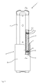
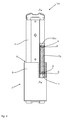
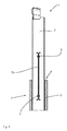
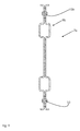
- Ausführungsbeispiele der Erfindung werden nachstehend mit Bezug auf die Zeichnungen näher erläutert. In den Zeichnungen zeigen:
- Fig. 1
- eine perspektivische Ansicht einer ersten Ausführungsform eines Überrollschutzsystems;
- Fig. 2
- eine Vorderansicht des Überrollschutzsystems von
Fig. 1 , teilweise im Schnitt; - Fig. 3
- eine Schnittansicht des Überrollschutzsystems von
Fig. 1 ; - Fig. 4
- eine Vorderansicht einer zweiten Ausführungsform eines Überrollschutzsystems, teilweise im Schnitt;
- Fig. 5
- eine Schnittansicht des Überrollschutzsystems von
Fig. 4 ; - Fig. 6
- eine Vorderansicht eines Verstärkungselements des Überrollschutzsystems von
Fig. 4 ; - Fig. 7
- eine Vorderansicht einer dritten Ausführungsform eines Überrollschutzsystems, teilweise im Schnitt;
- Fig. 8
- eine Schnittansicht des Überrollschutzsystems von
Fig. 7 und - Fig. 9
- eine Schnittansicht einer weiteren Ausführungsform eines Verstärkungselements.
- In den
Figuren 1 bis 3 ist ein erstes Ausführungsbeispiel eines erfindungsgemäßen Überrollschutzsystems 1 dargestellt. Das Überrollschutzsystem 1 weist eine durch ein Außenprofil 5 gebildete Führungseinheit 3 auf, über die das Überrollschutzsystem 1 an einem hier nicht dargestellten Fahrzeug befestigt wird. Die Ausrichtung des Überrollschutzsystems 1 erfolgt dabei derart, dass sich das Überrollschutzsystem 1 in Fahrzeugquerachsenrichtung in YRichtung - bezogen auf das in der Zeichnung dargestellte Koordinatensystem - erstreckt. Die Ausfahrbewegung eines verstellbar an der Führungseinheit 3 gelagerten Überrollkörpers 2 erfolgt in Fahrzeughochachsenrichtung, welche der in den Zeichnungen dargestellten Z-Achse entspricht. In der Einbaulage ist damit das Überrollschutzsystem 1 quer zur Fahrzeuglängsachsenrichtung angeordnet, die der X-Achse in dem inFigur 1 dargestellten Koordinatensystem entspricht. - Die Ausfahrbewegung des Überrollkörpers 2, bei der dieser innerhalb des Außenprofils 5 in die in den Zeichnungen dargestellten Überschlagsposition bewegt wird, erfolgt mittels einer hier nicht dargestellten Antriebseinheit. In der Überschlagsposition bildet die Oberseite des Außenprofils 5 eine Biegekante 4 für den Überrollkörper 2. Verformungen des Überrollkörpers 2 in X- und Y-Achsenrichtung erfolgen aufgrund der bei einem Überschlag auftretenden Belastungen im Wesentlichen im Bereich der Biegekante 4.
- Zur Erhöhung der Biegesteifigkeit des Überrollkörpers 2 gegenüber in Fahrzeugquerachsenrichtung - in Y-Achsenrichtung - wirkenden Kräften ist an dem Überrollkörper 2 ein als Strebe 7 ausgebildetes Verstärkungselement angeordnet. Das Verstärkungselement erstreckt sich in der Überschlagsposition des Überrollkörpers 2 zwischen zwei Befestigungspunkten aus einem Bereich innerhalb der Führungseinheit 3 in einen Bereich außerhalb der Führungseinheit 3 über die Biegekante 4 hinaus. Die Befestigung der Strebe 7 erfolgt dabei über Niete 6, die sich durch entsprechende Öffnungen 10 an den Strebenenden erstrecken. Zur ortsfesten Festlegung der Niete 6 dient ein Nietschließkopf 11, welcher innerhalb eines Schlitzes 8 der Strebe 7 angeordnet ist.
- Ein zweites Ausführungsbeispiel eines Überrollschutzsystems 1a ist in den
Figuren 4 bis 6 dargestellt. Das Überrollschutzsystem 1a unterscheidet sich von dem in denFiguren 1 bis 3 dargestellten Überrollschutzsystems 1 dadurch, dass das Verstärkungselement durch eine Kunststoffstrebe 7a gebildet ist. Die Kunststoffstrebe 7a weist neben einem flachen Ab-schnitt im Bereich der Biegekante 4, wenn der Überrollkörper 2 in der dargestellten Überschlagsposition angeordnet ist, im Bereich der Enden der Strebe 7a Stützkörper 9a auf, über die die Strebe 7a innerhalb des als Hohlprofil ausgebildeten Überrollkörpers 2 an den Innenflächen des Überrollkörpers 2 abgestützt ist. - In dem in den
Figuren 7 und8 dargestellten weiteren Ausführungsbeispiel eines Überrollschutzsystems 1b ist eine weitere Ausführungsform einer Strebe 7b dargestellt, die aus zwei Stahlblechen gebildet ist, die mittels einer Verschweißung, bevorzugt einer Punktverschweißung miteinander verbunden sind. - Eine dritte Ausführungsform einer Strebe 7c ist in
Figur 9 dargestellt, wobei diese Strebe 7c analog zu der inFigur 8 dargestellten Strebe 7b durch zwei Stahlbleche gebildet ist. Darüber hinaus weist die Strebe 7c zwei im Abstand von der Biegekante 4 - bezogen auf die Überschlagsposition des Überrollkörpers 2 - angeordnete Stützkörper 9b auf, die durch Verprägungen der Stahlbleche gebildet sind. Über die als Stützkörper 9b wirkenden Verprägungen kann die Strebe 7c am Inneren des Hohlprofils abgestützt werden. -
- 1, 1a, 1b
- Überrollschutzsystem
- 2
- Überrollkörper/Hohlprofil
- 3
- Führungseinheit
- 4
- Biegekante
- 5
- Außenprofil
- 6
- Niet
- 7, 7a, 7b, 7c
- Verstärkungselement/Strebe
- 8
- Schlitz
- 9a, 9b
- Stützkörper
- 10, 10a, 10b
- Öffnung
- 11
- Nietschließkopf
Claims (7)
- Überrollschutzsystem für Kraftfahrzeuge, mit- einer an einem Kraftfahrzeug anordbaren Führungseinheit (3) und- einem im Wesentlichen senkrecht zur Kraftfahrzeuglängsachse und Kraftfahrzeugquerachse zwischen einer Lagerungsposition und einer Überschlagsposition verstellbar an der Führungseinheit (3) gelagerten Überrollkörper (2),dadurch gekennzeichnet, dass
an dem Überrollkörper (2) ein Verstärkungselement (7, 7a, 7b, 7c) angeordnet ist, das sich in der Überschlagsposition des Überrollkörpers (2) in Ausfahrrichtung aus einem Bereich innerhalb der Führungseinheit (3) über eine Biegekante (4) hinaus in einen Bereich außerhalb der Führungseinheit (2) erstreckt. - Überrollschutzsystem nach Anspruch 1, dadurch gekennzeichnet, dass das Verstärkungselement (7, 7a, 7b, 7c) derart ausgebildet ist, dass die Biegesteifigkeit des Überrollkörpers (2) in Fahrzeugquerachsenrichtung erhöht und in Fahrzeuglängsachsenrichtung im Bereich der Biegekante (4) im Wesentlichen beibehalten wird.
- Überrollschutzsystem nach Anspruch 1 oder 2, dadurch gekennzeichnet, dass das Verstärkungselement als Strebe (7, 7a, 7b, 7c) ausgebildet ist, deren Erstreckung in der Überschlagsposition des Überrollkörpers (2) in Fahrzeugquerachsenrichtung im Bereich der Biegekante (4) mehr als das 2-fache, bevorzugt mehr als das 4-fache, besonders bevorzugt mehr als das 8-fache deren Erstreckung in Fahrzeuglängsachsenrichtung beträgt.
- Überrollschutzsystem nach einem der vorhergehenden Ansprüche, dadurch gekennzeichnet, dass die Strebe (7, 7a, 7b, 7c) im Inneren eines als Hohlprofil (2) ausgebildeten Überrollkörpers angeordnet ist.
- Überrollschutzsystem nach einem der vorhergehenden Ansprüche, dadurch gekennzeichnet, dass die Strebe (7, 7a, 7b, 7c) formschlüssig mit dem Überrollkörper (2) verbunden, insbesondere mit dem Überrollkörper (2) vernietet ist.
- Überrollschutzsystem nach einem der vorhergehenden Ansprüche, dadurch gekennzeichnet, dass die Strebe (7a, 7b, 7c) einen, bevorzugt zwei sich in Fahrzeuglängsachsenrichtung erstreckende, an dem Überrollkörper (2) anliegende Stützkörper (9, 9a) aufweist, die in der Überschlagsposition des Überrollkörpers (2) im Abstand von der Biegekante (4) angeordnet ist.
- Überrollschutzsystem nach einem der vorhergehenden Ansprüche, dadurch gekennzeichnet, dass die Stützkörper durch Verprägungen (9) einer metallischen Strebe (7c) gebildet sind.
Priority Applications (1)
| Application Number | Priority Date | Filing Date | Title |
|---|---|---|---|
| EP14185343.2A EP2998170B1 (de) | 2014-09-18 | 2014-09-18 | Überrollschutzsystem für Kraftfahrzeuge |
Applications Claiming Priority (1)
| Application Number | Priority Date | Filing Date | Title |
|---|---|---|---|
| EP14185343.2A EP2998170B1 (de) | 2014-09-18 | 2014-09-18 | Überrollschutzsystem für Kraftfahrzeuge |
Publications (2)
| Publication Number | Publication Date |
|---|---|
| EP2998170A1 true EP2998170A1 (de) | 2016-03-23 |
| EP2998170B1 EP2998170B1 (de) | 2018-11-14 |
Family
ID=51542279
Family Applications (1)
| Application Number | Title | Priority Date | Filing Date |
|---|---|---|---|
| EP14185343.2A Not-in-force EP2998170B1 (de) | 2014-09-18 | 2014-09-18 | Überrollschutzsystem für Kraftfahrzeuge |
Country Status (1)
| Country | Link |
|---|---|
| EP (1) | EP2998170B1 (de) |
Citations (1)
| Publication number | Priority date | Publication date | Assignee | Title |
|---|---|---|---|---|
| DE19712955A1 (de) * | 1997-03-27 | 1998-10-01 | Bayerische Motoren Werke Ag | Überrollschutzsystem für ein Fahrzeug, insbesondere für ein Cabriolet |
Family Cites Families (2)
| Publication number | Priority date | Publication date | Assignee | Title |
|---|---|---|---|---|
| EP2239166B1 (de) * | 2010-01-19 | 2013-05-29 | ISE Automotive GmbH | Überrollschutzsystem für Kraftfahrzeuge |
| EP2329996B1 (de) * | 2010-09-23 | 2013-08-28 | ISE Automotive GmbH | Überrollkörperantriebseinheit zur Verlagerung eines Überrollkörpers aus einer Lagerungsposition in eine Überschlagsposition sowie ein Überrollschutzsystem für Kraftfahrzeuge |
-
2014
- 2014-09-18 EP EP14185343.2A patent/EP2998170B1/de not_active Not-in-force
Patent Citations (1)
| Publication number | Priority date | Publication date | Assignee | Title |
|---|---|---|---|---|
| DE19712955A1 (de) * | 1997-03-27 | 1998-10-01 | Bayerische Motoren Werke Ag | Überrollschutzsystem für ein Fahrzeug, insbesondere für ein Cabriolet |
Also Published As
| Publication number | Publication date |
|---|---|
| EP2998170B1 (de) | 2018-11-14 |
Similar Documents
| Publication | Publication Date | Title |
|---|---|---|
| DE102008042527B4 (de) | Überrollschutzsystem mit ausschwenkbarem Überrollkörper | |
| DE102007026951A1 (de) | Sitzträgeranordnung und Aufbau für einen Omnibus | |
| WO2016045775A1 (de) | Insassenrückhaltesystem für ein fahrzeug | |
| DE102013015615B4 (de) | Frontstruktur für ein Kraftfahrzeug | |
| EP2018295B1 (de) | Strukturelement für fahrzeugsitz | |
| DE102013106297A1 (de) | Karosserieanordnung mit einer Schutzanordnung für sicherheitsrelevante Teile im Kraftfahrzeugbereich | |
| EP2998170B1 (de) | Überrollschutzsystem für Kraftfahrzeuge | |
| DE102016214579A1 (de) | Querträger und Cockpit-Modul | |
| DE202014010267U1 (de) | Trägerstruktur für einen Sitz eines Kraftfahrzeugs | |
| DE102012007841B4 (de) | Anordnung einer Sonnenschutzeinrichtung an einem Dach eines Kraftwagens | |
| DE102004056359B3 (de) | Überrollschutzeinrichtung | |
| DE102009048391B4 (de) | Fahrzeugstoßfänger und Fahrzeug | |
| EP2343221B1 (de) | Überrollschutzsystem für Kraftfahrzeuge | |
| EP1517814A1 (de) | Stossfängertragstruktur eines kraftfahrzeuges | |
| DE102015218406A1 (de) | Seitentür für ein Fahrzeug und Fahrzeug mit einer derartigen Seitentür | |
| EP3766765A1 (de) | Kabine für eine landwirtschaftliche arbeitsmaschine | |
| DE102005046891A1 (de) | Heckklappe eines Kraftfahrzeugs | |
| DE102009011340A1 (de) | Stoßfängeranordnung für einen Personenkraftwagen | |
| EP2246222B1 (de) | Überrollschutzsytem für Kraftfahrzeuge | |
| EP2209673B1 (de) | Fahrzeugsitz und sicherheitsgurtsystem | |
| DE102009051031B3 (de) | Luftausströmer für Fahrzeuge | |
| DE102021112458A1 (de) | Kraftfahrzeug mit einem Fensterheber | |
| DE102009028532A1 (de) | Tragschienenvorrichtung zum Tragen eines Moduls eines Luft- und Raumfahrzeugs | |
| EP2581274B1 (de) | Überrollkörper für ein Überrollschutzsystem eines Kraftfahrzeuges | |
| EP2347936B1 (de) | Überrollschutzsystem für Kraftfahrzeuge |
Legal Events
| Date | Code | Title | Description |
|---|---|---|---|
| PUAI | Public reference made under article 153(3) epc to a published international application that has entered the european phase |
Free format text: ORIGINAL CODE: 0009012 |
|
| AK | Designated contracting states |
Kind code of ref document: A1 Designated state(s): AL AT BE BG CH CY CZ DE DK EE ES FI FR GB GR HR HU IE IS IT LI LT LU LV MC MK MT NL NO PL PT RO RS SE SI SK SM TR |
|
| AX | Request for extension of the european patent |
Extension state: BA ME |
|
| 17P | Request for examination filed |
Effective date: 20160923 |
|
| RBV | Designated contracting states (corrected) |
Designated state(s): AL AT BE BG CH CY CZ DE DK EE ES FI FR GB GR HR HU IE IS IT LI LT LU LV MC MK MT NL NO PL PT RO RS SE SI SK SM TR |
|
| STAA | Information on the status of an ep patent application or granted ep patent |
Free format text: STATUS: EXAMINATION IS IN PROGRESS |
|
| 17Q | First examination report despatched |
Effective date: 20170623 |
|
| GRAP | Despatch of communication of intention to grant a patent |
Free format text: ORIGINAL CODE: EPIDOSNIGR1 |
|
| STAA | Information on the status of an ep patent application or granted ep patent |
Free format text: STATUS: GRANT OF PATENT IS INTENDED |
|
| INTG | Intention to grant announced |
Effective date: 20180504 |
|
| GRAS | Grant fee paid |
Free format text: ORIGINAL CODE: EPIDOSNIGR3 |
|
| GRAJ | Information related to disapproval of communication of intention to grant by the applicant or resumption of examination proceedings by the epo deleted |
Free format text: ORIGINAL CODE: EPIDOSDIGR1 |
|
| GRAL | Information related to payment of fee for publishing/printing deleted |
Free format text: ORIGINAL CODE: EPIDOSDIGR3 |
|
| STAA | Information on the status of an ep patent application or granted ep patent |
Free format text: STATUS: EXAMINATION IS IN PROGRESS |
|
| INTC | Intention to grant announced (deleted) | ||
| GRAP | Despatch of communication of intention to grant a patent |
Free format text: ORIGINAL CODE: EPIDOSNIGR1 |
|
| STAA | Information on the status of an ep patent application or granted ep patent |
Free format text: STATUS: GRANT OF PATENT IS INTENDED |
|
| GRAA | (expected) grant |
Free format text: ORIGINAL CODE: 0009210 |
|
| STAA | Information on the status of an ep patent application or granted ep patent |
Free format text: STATUS: THE PATENT HAS BEEN GRANTED |
|
| INTG | Intention to grant announced |
Effective date: 20180917 |
|
| RIN1 | Information on inventor provided before grant (corrected) |
Inventor name: NASS, MICHAEL |
|
| AK | Designated contracting states |
Kind code of ref document: B1 Designated state(s): AL AT BE BG CH CY CZ DE DK EE ES FI FR GB GR HR HU IE IS IT LI LT LU LV MC MK MT NL NO PL PT RO RS SE SI SK SM TR |
|
| REG | Reference to a national code |
Ref country code: CH Ref legal event code: EP Ref country code: AT Ref legal event code: REF Ref document number: 1064417 Country of ref document: AT Kind code of ref document: T Effective date: 20181115 |
|
| REG | Reference to a national code |
Ref country code: IE Ref legal event code: FG4D Free format text: LANGUAGE OF EP DOCUMENT: GERMAN |
|
| REG | Reference to a national code |
Ref country code: DE Ref legal event code: R096 Ref document number: 502014010046 Country of ref document: DE |
|
| REG | Reference to a national code |
Ref country code: NL Ref legal event code: MP Effective date: 20181114 |
|
| REG | Reference to a national code |
Ref country code: LT Ref legal event code: MG4D |
|
| PG25 | Lapsed in a contracting state [announced via postgrant information from national office to epo] |
Ref country code: LT Free format text: LAPSE BECAUSE OF FAILURE TO SUBMIT A TRANSLATION OF THE DESCRIPTION OR TO PAY THE FEE WITHIN THE PRESCRIBED TIME-LIMIT Effective date: 20181114 Ref country code: HR Free format text: LAPSE BECAUSE OF FAILURE TO SUBMIT A TRANSLATION OF THE DESCRIPTION OR TO PAY THE FEE WITHIN THE PRESCRIBED TIME-LIMIT Effective date: 20181114 Ref country code: LV Free format text: LAPSE BECAUSE OF FAILURE TO SUBMIT A TRANSLATION OF THE DESCRIPTION OR TO PAY THE FEE WITHIN THE PRESCRIBED TIME-LIMIT Effective date: 20181114 Ref country code: NO Free format text: LAPSE BECAUSE OF FAILURE TO SUBMIT A TRANSLATION OF THE DESCRIPTION OR TO PAY THE FEE WITHIN THE PRESCRIBED TIME-LIMIT Effective date: 20190214 Ref country code: ES Free format text: LAPSE BECAUSE OF FAILURE TO SUBMIT A TRANSLATION OF THE DESCRIPTION OR TO PAY THE FEE WITHIN THE PRESCRIBED TIME-LIMIT Effective date: 20181114 Ref country code: BG Free format text: LAPSE BECAUSE OF FAILURE TO SUBMIT A TRANSLATION OF THE DESCRIPTION OR TO PAY THE FEE WITHIN THE PRESCRIBED TIME-LIMIT Effective date: 20190214 Ref country code: IS Free format text: LAPSE BECAUSE OF FAILURE TO SUBMIT A TRANSLATION OF THE DESCRIPTION OR TO PAY THE FEE WITHIN THE PRESCRIBED TIME-LIMIT Effective date: 20190314 Ref country code: FI Free format text: LAPSE BECAUSE OF FAILURE TO SUBMIT A TRANSLATION OF THE DESCRIPTION OR TO PAY THE FEE WITHIN THE PRESCRIBED TIME-LIMIT Effective date: 20181114 |
|
| PG25 | Lapsed in a contracting state [announced via postgrant information from national office to epo] |
Ref country code: GR Free format text: LAPSE BECAUSE OF FAILURE TO SUBMIT A TRANSLATION OF THE DESCRIPTION OR TO PAY THE FEE WITHIN THE PRESCRIBED TIME-LIMIT Effective date: 20190215 Ref country code: RS Free format text: LAPSE BECAUSE OF FAILURE TO SUBMIT A TRANSLATION OF THE DESCRIPTION OR TO PAY THE FEE WITHIN THE PRESCRIBED TIME-LIMIT Effective date: 20181114 Ref country code: AL Free format text: LAPSE BECAUSE OF FAILURE TO SUBMIT A TRANSLATION OF THE DESCRIPTION OR TO PAY THE FEE WITHIN THE PRESCRIBED TIME-LIMIT Effective date: 20181114 Ref country code: PT Free format text: LAPSE BECAUSE OF FAILURE TO SUBMIT A TRANSLATION OF THE DESCRIPTION OR TO PAY THE FEE WITHIN THE PRESCRIBED TIME-LIMIT Effective date: 20190314 Ref country code: SE Free format text: LAPSE BECAUSE OF FAILURE TO SUBMIT A TRANSLATION OF THE DESCRIPTION OR TO PAY THE FEE WITHIN THE PRESCRIBED TIME-LIMIT Effective date: 20181114 Ref country code: NL Free format text: LAPSE BECAUSE OF FAILURE TO SUBMIT A TRANSLATION OF THE DESCRIPTION OR TO PAY THE FEE WITHIN THE PRESCRIBED TIME-LIMIT Effective date: 20181114 |
|
| PG25 | Lapsed in a contracting state [announced via postgrant information from national office to epo] |
Ref country code: PL Free format text: LAPSE BECAUSE OF FAILURE TO SUBMIT A TRANSLATION OF THE DESCRIPTION OR TO PAY THE FEE WITHIN THE PRESCRIBED TIME-LIMIT Effective date: 20181114 Ref country code: IT Free format text: LAPSE BECAUSE OF FAILURE TO SUBMIT A TRANSLATION OF THE DESCRIPTION OR TO PAY THE FEE WITHIN THE PRESCRIBED TIME-LIMIT Effective date: 20181114 Ref country code: DK Free format text: LAPSE BECAUSE OF FAILURE TO SUBMIT A TRANSLATION OF THE DESCRIPTION OR TO PAY THE FEE WITHIN THE PRESCRIBED TIME-LIMIT Effective date: 20181114 Ref country code: CZ Free format text: LAPSE BECAUSE OF FAILURE TO SUBMIT A TRANSLATION OF THE DESCRIPTION OR TO PAY THE FEE WITHIN THE PRESCRIBED TIME-LIMIT Effective date: 20181114 |
|
| REG | Reference to a national code |
Ref country code: DE Ref legal event code: R097 Ref document number: 502014010046 Country of ref document: DE |
|
| PG25 | Lapsed in a contracting state [announced via postgrant information from national office to epo] |
Ref country code: RO Free format text: LAPSE BECAUSE OF FAILURE TO SUBMIT A TRANSLATION OF THE DESCRIPTION OR TO PAY THE FEE WITHIN THE PRESCRIBED TIME-LIMIT Effective date: 20181114 Ref country code: SK Free format text: LAPSE BECAUSE OF FAILURE TO SUBMIT A TRANSLATION OF THE DESCRIPTION OR TO PAY THE FEE WITHIN THE PRESCRIBED TIME-LIMIT Effective date: 20181114 Ref country code: EE Free format text: LAPSE BECAUSE OF FAILURE TO SUBMIT A TRANSLATION OF THE DESCRIPTION OR TO PAY THE FEE WITHIN THE PRESCRIBED TIME-LIMIT Effective date: 20181114 Ref country code: SM Free format text: LAPSE BECAUSE OF FAILURE TO SUBMIT A TRANSLATION OF THE DESCRIPTION OR TO PAY THE FEE WITHIN THE PRESCRIBED TIME-LIMIT Effective date: 20181114 |
|
| PLBE | No opposition filed within time limit |
Free format text: ORIGINAL CODE: 0009261 |
|
| STAA | Information on the status of an ep patent application or granted ep patent |
Free format text: STATUS: NO OPPOSITION FILED WITHIN TIME LIMIT |
|
| 26N | No opposition filed |
Effective date: 20190815 |
|
| PG25 | Lapsed in a contracting state [announced via postgrant information from national office to epo] |
Ref country code: SI Free format text: LAPSE BECAUSE OF FAILURE TO SUBMIT A TRANSLATION OF THE DESCRIPTION OR TO PAY THE FEE WITHIN THE PRESCRIBED TIME-LIMIT Effective date: 20181114 |
|
| PG25 | Lapsed in a contracting state [announced via postgrant information from national office to epo] |
Ref country code: TR Free format text: LAPSE BECAUSE OF FAILURE TO SUBMIT A TRANSLATION OF THE DESCRIPTION OR TO PAY THE FEE WITHIN THE PRESCRIBED TIME-LIMIT Effective date: 20181114 |
|
| PG25 | Lapsed in a contracting state [announced via postgrant information from national office to epo] |
Ref country code: MC Free format text: LAPSE BECAUSE OF FAILURE TO SUBMIT A TRANSLATION OF THE DESCRIPTION OR TO PAY THE FEE WITHIN THE PRESCRIBED TIME-LIMIT Effective date: 20181114 |
|
| REG | Reference to a national code |
Ref country code: CH Ref legal event code: PL |
|
| PG25 | Lapsed in a contracting state [announced via postgrant information from national office to epo] |
Ref country code: LU Free format text: LAPSE BECAUSE OF NON-PAYMENT OF DUE FEES Effective date: 20190918 Ref country code: LI Free format text: LAPSE BECAUSE OF NON-PAYMENT OF DUE FEES Effective date: 20190930 Ref country code: CH Free format text: LAPSE BECAUSE OF NON-PAYMENT OF DUE FEES Effective date: 20190930 Ref country code: IE Free format text: LAPSE BECAUSE OF NON-PAYMENT OF DUE FEES Effective date: 20190918 |
|
| REG | Reference to a national code |
Ref country code: BE Ref legal event code: MM Effective date: 20190930 |
|
| PG25 | Lapsed in a contracting state [announced via postgrant information from national office to epo] |
Ref country code: BE Free format text: LAPSE BECAUSE OF NON-PAYMENT OF DUE FEES Effective date: 20190930 |
|
| GBPC | Gb: european patent ceased through non-payment of renewal fee |
Effective date: 20190918 |
|
| PG25 | Lapsed in a contracting state [announced via postgrant information from national office to epo] |
Ref country code: FR Free format text: LAPSE BECAUSE OF NON-PAYMENT OF DUE FEES Effective date: 20190930 Ref country code: GB Free format text: LAPSE BECAUSE OF NON-PAYMENT OF DUE FEES Effective date: 20190918 |
|
| REG | Reference to a national code |
Ref country code: AT Ref legal event code: MM01 Ref document number: 1064417 Country of ref document: AT Kind code of ref document: T Effective date: 20190918 |
|
| PG25 | Lapsed in a contracting state [announced via postgrant information from national office to epo] |
Ref country code: AT Free format text: LAPSE BECAUSE OF NON-PAYMENT OF DUE FEES Effective date: 20190918 |
|
| PG25 | Lapsed in a contracting state [announced via postgrant information from national office to epo] |
Ref country code: CY Free format text: LAPSE BECAUSE OF FAILURE TO SUBMIT A TRANSLATION OF THE DESCRIPTION OR TO PAY THE FEE WITHIN THE PRESCRIBED TIME-LIMIT Effective date: 20181114 |
|
| PG25 | Lapsed in a contracting state [announced via postgrant information from national office to epo] |
Ref country code: HU Free format text: LAPSE BECAUSE OF FAILURE TO SUBMIT A TRANSLATION OF THE DESCRIPTION OR TO PAY THE FEE WITHIN THE PRESCRIBED TIME-LIMIT; INVALID AB INITIO Effective date: 20140918 Ref country code: MT Free format text: LAPSE BECAUSE OF FAILURE TO SUBMIT A TRANSLATION OF THE DESCRIPTION OR TO PAY THE FEE WITHIN THE PRESCRIBED TIME-LIMIT Effective date: 20181114 |
|
| PG25 | Lapsed in a contracting state [announced via postgrant information from national office to epo] |
Ref country code: MK Free format text: LAPSE BECAUSE OF FAILURE TO SUBMIT A TRANSLATION OF THE DESCRIPTION OR TO PAY THE FEE WITHIN THE PRESCRIBED TIME-LIMIT Effective date: 20181114 |
|
| PGFP | Annual fee paid to national office [announced via postgrant information from national office to epo] |
Ref country code: DE Payment date: 20220426 Year of fee payment: 9 |
|
| P01 | Opt-out of the competence of the unified patent court (upc) registered |
Effective date: 20230531 |
|
| REG | Reference to a national code |
Ref country code: DE Ref legal event code: R119 Ref document number: 502014010046 Country of ref document: DE |
|
| PG25 | Lapsed in a contracting state [announced via postgrant information from national office to epo] |
Ref country code: DE Free format text: LAPSE BECAUSE OF NON-PAYMENT OF DUE FEES Effective date: 20240403 |