EP2998024B1 - Method for regenerating cos conversion catalyst - Google Patents
Method for regenerating cos conversion catalyst Download PDFInfo
- Publication number
- EP2998024B1 EP2998024B1 EP14855014.8A EP14855014A EP2998024B1 EP 2998024 B1 EP2998024 B1 EP 2998024B1 EP 14855014 A EP14855014 A EP 14855014A EP 2998024 B1 EP2998024 B1 EP 2998024B1
- Authority
- EP
- European Patent Office
- Prior art keywords
- hydrolysis catalyst
- cos
- catalyst
- cos hydrolysis
- acid
- Prior art date
- Legal status (The legal status is an assumption and is not a legal conclusion. Google has not performed a legal analysis and makes no representation as to the accuracy of the status listed.)
- Active
Links
Images

Classifications
-
- B—PERFORMING OPERATIONS; TRANSPORTING
- B01—PHYSICAL OR CHEMICAL PROCESSES OR APPARATUS IN GENERAL
- B01J—CHEMICAL OR PHYSICAL PROCESSES, e.g. CATALYSIS OR COLLOID CHEMISTRY; THEIR RELEVANT APPARATUS
- B01J38/00—Regeneration or reactivation of catalysts, in general
- B01J38/48—Liquid treating or treating in liquid phase, e.g. dissolved or suspended
- B01J38/64—Liquid treating or treating in liquid phase, e.g. dissolved or suspended using alkaline material; using salts
-
- B—PERFORMING OPERATIONS; TRANSPORTING
- B01—PHYSICAL OR CHEMICAL PROCESSES OR APPARATUS IN GENERAL
- B01J—CHEMICAL OR PHYSICAL PROCESSES, e.g. CATALYSIS OR COLLOID CHEMISTRY; THEIR RELEVANT APPARATUS
- B01J38/00—Regeneration or reactivation of catalysts, in general
- B01J38/48—Liquid treating or treating in liquid phase, e.g. dissolved or suspended
- B01J38/60—Liquid treating or treating in liquid phase, e.g. dissolved or suspended using acids
-
- B—PERFORMING OPERATIONS; TRANSPORTING
- B01—PHYSICAL OR CHEMICAL PROCESSES OR APPARATUS IN GENERAL
- B01J—CHEMICAL OR PHYSICAL PROCESSES, e.g. CATALYSIS OR COLLOID CHEMISTRY; THEIR RELEVANT APPARATUS
- B01J23/00—Catalysts comprising metals or metal oxides or hydroxides, not provided for in group B01J21/00
- B01J23/90—Regeneration or reactivation
- B01J23/92—Regeneration or reactivation of catalysts comprising metals, oxides or hydroxides provided for in groups B01J23/02 - B01J23/36
Definitions
- the present invention relates to a method for regenerating a COS hydrolysis catalyst.
- a low-quality fuel typically contains a large amount of sulfur compounds, and when a gas obtained by gasifying this fuel is combusted directly, the sulfur compounds are discharged from the chimney into the atmosphere as sulfur oxides, which become a source of environmental pollution such as acid rain. Therefore, in ordinary thermal power generation, a method of installing an exhaust gas desulfurizer on the downstream side of the boiler so as to remove sulfur compounds as gypsum, for example, has been put into practical application.
- the inlet temperature of a gas turbine is higher than the boiler temperature in ordinary thermal power generation, so the corrosion of the material is substantial. Therefore, it is necessary to protect the material by removing various impurities such as sulfur compounds on the upstream side rather than the downstream side of the gas turbine. For example, when installing a fuel cell power generator, it is essential to secure power generation efficiency and durability by protecting the material, and various impurities must be similarly removed on the upstream side of the fuel cell.
- examples of known COS hydrolysis catalysts include catalysts containing titania, catalysts containing alumina, a group IV metal and barium, and catalysts containing an alkali metal, chromium oxide, and alumina (Patent Document 1).
- the catalyst with reduced performance as a result of poisoning is reused by means of regeneration treatment.
- Patent Document 2 A method of performing heat treatment on a catalyst and then re-supporting sodium carbonate, for example, has been proposed as such a catalyst regeneration method (Patent Document 2).
- a method for regenerating a COS catalyst according to conventional technology has a problem in that since the active component of the catalyst is once again supported, the cost of relatively expensive chemicals such as potassium carbonate and sodium carbonate increases.
- an object of the present invention is to provide a method for inexpensively regenerating a COS hydrolysis catalyst.
- the invention is defined by the claims.
- the present invention relates to a method for regenerating a carbonyl sulfide (COS) hydrolysis catalyst, wherein the spent COS hydrolysis catalyst is a Ba/TiO 2 honeycomb-type catalyst which is immersed in an alkaline solution for a prescribed amount of time and then immersed in an acid for a prescribed amount of time.
- COS carbonyl sulfide
- the immersion is performed at a temperature of from 60°C to 80°C.
- poisoning components adhering to a COS hydrolysis catalyst can be removed by performing chemical washing with an alkali and an acid, which makes it possible to reuse the substance.
- the method for regenerating a COS hydrolysis catalyst according to Embodiment 1 is a method for regenerating a carbonyl sulfide (COS) hydrolysis catalyst by hydrolyzing COS which is contained in a gas obtained by gasifying a carbon raw material such as coal, for example, wherein a spent COS hydrolysis catalyst is immersed in an acid for a prescribed amount of time.
- COS carbonyl sulfide
- Drying may be performed by means of natural drying or heat drying.
- the temperature is preferably from 80°C to 200°C and particularly preferably from 110°C to 150°C.
- step (2) the dust removal by means of air blowing in step (2) can be omitted depending on the amount of dust adhering to the catalyst.
- the method for regenerating a COS hydrolysis catalyst according to Embodiment 2 is a method for regenerating a carbonyl sulfide (COS) hydrolysis catalyst by hydrolyzing COS which is contained in a gas obtained by gasifying a carbon raw material such as coal, for example, wherein a spent COS hydrolysis catalyst is immersed in an alkaline solution for a prescribed amount of time.
- COS carbonyl sulfide
- Drying may be performed by means of natural drying or heat drying.
- the substance may also be calcined.
- the method for regenerating a COS hydrolysis catalyst according to Embodiment 3 is a method for regenerating a carbonyl sulfide (COS) hydrolysis catalyst by hydrolyzing COS which is contained in a gas obtained by gasifying a carbon raw material such as coal, for example, wherein a spent COS hydrolysis catalyst, namely a spent Ba/TiO 2 honeycomb-type catalyst is immersed in an alkaline solution for a prescribed amount of time and then immersed in an acid for a prescribed amount of time.
- COS hydrolysis catalyst namely a spent Ba/TiO 2 honeycomb-type catalyst
- Drying may be performed by means of natural drying or heat drying.
- the substance may also be calcined.
- Embodiment 4 is a method for regenerating a carbonyl sulfide (COS) hydrolysis catalyst by hydrolyzing COS which is contained in a gas obtained by gasifying a carbon raw material such as coal, for example, wherein a spent COS hydrolysis catalyst is immersed in an acid for a prescribed amount of time and then immersed in an alkaline solution for a prescribed amount of time.
- COS carbonyl sulfide
- Drying may be performed by means of natural drying or heat drying.
- the substance may also be calcined.
- test examples will be described, but the present invention is not limited to these test examples.
- Test Example 1 (not according to the invention), a spent COS hydrolysis catalyst is immersed in 1 N sulfuric acid for 30 minutes at room temperature and then washed with water for 30 minutes.
- Test Example 2 (not according to the invention), a spent COS hydrolysis catalyst is immersed in 1 N sulfuric acid for 30 minutes while heating (60°C) and then washed with water for 30 minutes.
- Test Example 3 a spent COS hydrolysis catalyst is immersed in a 1 N sodium hydroxide aqueous solution for 30 minutes at room temperature, and the alkali-treated COS hydrolysis catalyst is then neutralized by means of immersion in 1 N sulfuric acid for 30 minutes at room temperature and then washed with water for 30 minutes.
- the COS hydrolysis catalyst used in these tests is a Ba/TiO 2 honeycomb-type catalyst, and the temperature at which the COS conversion rate of the regenerated product was measured was 300°C.
- K is a reaction rate constant of the COS hydrolysis catalyst after regeneration
- K 0 is a reaction rate constant of a fresh COS hydrolysis catalyst.
- the recovery rate is at least 80%, so in contrast to conventional cases in which a catalyst component is newly re-supported with a chemical, it was possible to establish a method for inexpensively regenerating a COS hydrolysis catalyst.
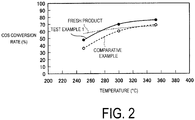
- FIG. 2 illustrates the relationship between the change in temperature of a COS hydrolysis catalyst and the COS conversion rate.
- Test Example 1 As illustrated in FIG. 2 , it was confirmed that the substances of Test Example 1 (acid-treated products) always have a higher COS conversion rate than a catalyst prior to regeneration.
- the acid-treated products have a higher COS conversion rate than a fresh product from a temperature range exceeding approximately 270°C.
Landscapes
- Chemical & Material Sciences (AREA)
- Engineering & Computer Science (AREA)
- Materials Engineering (AREA)
- Organic Chemistry (AREA)
- Chemical Kinetics & Catalysis (AREA)
- Catalysts (AREA)
- Indication Of The Valve Opening Or Closing Status (AREA)
Description
- The present invention relates to a method for regenerating a COS hydrolysis catalyst.
- In recent years, there has been a demand for the effective utilization of low-quality fuels such as coal or heavy oil from the perspective of diversification so as to actively use low-quality fossil fuels in addition to high-quality fossil fuels. In addition, integrated coal gasification combined cycle (IGCC), in which gas turbines using gas fuel and steam turbines are used in combination, and power generation by means of introducing hydrocarbon gas into fuel cells are also becoming widespread from the perspective of improving power generation efficiency in the field of thermal power generation. Therefore, there is research and development underway to gasify low-quality fuels and use them for such power generation.
- Incidentally, a low-quality fuel typically contains a large amount of sulfur compounds, and when a gas obtained by gasifying this fuel is combusted directly, the sulfur compounds are discharged from the chimney into the atmosphere as sulfur oxides, which become a source of environmental pollution such as acid rain. Therefore, in ordinary thermal power generation, a method of installing an exhaust gas desulfurizer on the downstream side of the boiler so as to remove sulfur compounds as gypsum, for example, has been put into practical application. However, in combined cycle power generation, the inlet temperature of a gas turbine is higher than the boiler temperature in ordinary thermal power generation, so the corrosion of the material is substantial. Therefore, it is necessary to protect the material by removing various impurities such as sulfur compounds on the upstream side rather than the downstream side of the gas turbine. For example, when installing a fuel cell power generator, it is essential to secure power generation efficiency and durability by protecting the material, and various impurities must be similarly removed on the upstream side of the fuel cell.
- A so-called wet gas purification process, wherein water-soluble components are removed with a water scrubber and hydrogen sulfide (H2S) is removed with an aqueous amine solution, has been put into practical application as such a method for removing impurities. However, although hydrogen sulfide (H2S) can be removed with an aqueous amine solution, carbonyl sulfide (COS) cannot be removed. Therefore, a hydrolysis reaction expressed by formula (1) is performed using a COS hydrolysis catalyst so as to accelerate a reaction for converting the substance into the form of hydrogen sulfide (H2S) which can be removed with an aqueous amine solution.
COS + H2O → H2S + CO2 ... (1)
- Here, examples of known COS hydrolysis catalysts include catalysts containing titania, catalysts containing alumina, a group IV metal and barium, and catalysts containing an alkali metal, chromium oxide, and alumina (Patent Document 1).
- Incidentally, in integrated coal gasification combined cycle (IGCC), there is a problem in that when a COS hydrolysis catalyst is used continuously for COS in a gasified gas, so-called catalyst poisoning occurs, wherein the dust content (for example, sulfides) in the gasified gas covers the surface of the COS hydrolysis catalyst, which causes a decrease in catalyst performance.
- The catalyst with reduced performance as a result of poisoning is reused by means of regeneration treatment.
- A method of performing heat treatment on a catalyst and then re-supporting sodium carbonate, for example, has been proposed as such a catalyst regeneration method (Patent Document 2).
-
- Patent Document 1: Japanese Unexamined Patent Application Publication No.
2004-75712A - Patent Document 2: Japanese Unexamined Patent Application Publication No.
2001-162174A - A method for regenerating a COS catalyst according to conventional technology has a problem in that since the active component of the catalyst is once again supported, the cost of relatively expensive chemicals such as potassium carbonate and sodium carbonate increases.
- Therefore, there is a demand for the emergence of a method for regenerating a COS hydrolysis catalyst without using relatively expensive chemicals, whereby catalyst regeneration is inexpensive.
- In light of the problem described above, an object of the present invention is to provide a method for inexpensively regenerating a COS hydrolysis catalyst. The invention is defined by the claims.
- The present invention relates to a method for regenerating a carbonyl sulfide (COS) hydrolysis catalyst, wherein the spent COS hydrolysis catalyst is a Ba/TiO2 honeycomb-type catalyst which is immersed in an alkaline solution for a prescribed amount of time and then immersed in an acid for a prescribed amount of time.
- By immersing the spent, degraded COS hydrolysis catalyst in an alkaline solution and then immersing the catalyst in an acid so as to neutralize the solution, poisoning components such as sulfides adhering to the catalyst surface are removed, which makes it possible to regenerate the catalyst.
- In a preferred embodiment of the method for regenerating a COS hydrolysis catalyst, the immersion is performed at a temperature of from 60°C to 80°C.
- By immersing the spent, degraded COS hydrolysis catalyst in an alkali and an acid in a heated state, poisoning components such as sulfides adhering to the catalyst surface are removed, which makes it possible to regenerate the catalyst.
- With the present invention, poisoning components adhering to a COS hydrolysis catalyst can be removed by performing chemical washing with an alkali and an acid, which makes it possible to reuse the substance.
-
-
FIG. 1 illustrates the results of testing the catalyst recovery rate under various conditions. -
FIG. 2 illustrates the relationship between the change in temperature of a COS hydrolysis catalyst and the COS conversion rate. - The following is a detailed description of preferred embodiments with reference to the attached drawings. Note that the invention is not limited by the embodiments, and when a plurality of embodiments are present, the invention may include a configuration combining these embodiments.
- The method for regenerating a COS hydrolysis catalyst according to
Embodiment 1 will be described. - The method for regenerating a COS hydrolysis catalyst according to
Embodiment 1 is a method for regenerating a carbonyl sulfide (COS) hydrolysis catalyst by hydrolyzing COS which is contained in a gas obtained by gasifying a carbon raw material such as coal, for example, wherein a spent COS hydrolysis catalyst is immersed in an acid for a prescribed amount of time. - The procedure of the method for regenerating a catalyst according to
Embodiment 1 will be described hereinafter. - (1) First, a COS hydrolysis catalyst with which a COS conversion device of a coal gasification power plant has been filled is extracted.
- (2) The dust content adhering to the extracted COS hydrolysis catalyst is removed by a gas spraying device such as an air blower.
- (3) Next, a prescribed amount of an acid is placed in an immersion vessel, and the air-blown COS hydrolysis catalyst is immersed in the acid. Here, the amount of the acid is at least an amount which allows the COS hydrolysis catalyst to be sufficiently hidden. More preferably, the amount is such that the volume ratio of the acid/COS hydrolysis catalyst is at least 3.
As the acid, sulfuric acid (H2SO4), hydrochloric acid (HCl), nitric acid (HNO3), or the like with a concentration of at least 0.1 N and approximately 1 N can be used.
In this chemical treatment, when the chemical solution is heated (for example, 60 to 80°C), the removal efficiency of adhering sulfides or the like improves. - (4) The substance is left and immersed for approximately 15 to 60 minutes in this immersed state.
- (5) The immersed COS hydrolysis catalyst is then immersed and water-washed in water (for example, ion-exchanged water) prepared in a separate vessel. Here, the amount of the water washing solution is at least an amount which allows the COS hydrolysis catalyst to be sufficiently hidden. More preferably, the amount is such that the volume ratio of water/COS hydrolysis catalyst is at least 3.
- (6) The substance is left and water-washed for approximately 15 to 60 minutes, for example, in this immersed state.
- (7) After water washing, the COS hydrolysis catalyst is taken out and dried after excess liquid in the catalyst is removed.
- Drying may be performed by means of natural drying or heat drying. Here, in the case of heat drying, the temperature is preferably from 80°C to 200°C and particularly preferably from 110°C to 150°C.
- By performing chemical washing with an acid in this way, poisoning components adhering to a COS hydrolysis catalyst can be removed, which makes it possible to reuse the substance.
- Here, the dust removal by means of air blowing in step (2) can be omitted depending on the amount of dust adhering to the catalyst.
- The method for regenerating a COS hydrolysis catalyst according to
Embodiment 2 will be described. - The method for regenerating a COS hydrolysis catalyst according to
Embodiment 2 is a method for regenerating a carbonyl sulfide (COS) hydrolysis catalyst by hydrolyzing COS which is contained in a gas obtained by gasifying a carbon raw material such as coal, for example, wherein a spent COS hydrolysis catalyst is immersed in an alkaline solution for a prescribed amount of time. - The procedure of the method for regenerating a catalyst according to
Embodiment 2 will be described hereinafter. - (1) First, a catalyst with which a COS conversion device of a coal gasification power plant has been filled is extracted.
- (2) The dust content adhering to the extracted COS hydrolysis catalyst is removed by a gas spraying device such as an air blower.
- (3) Next, a prescribed amount of an alkaline solution is placed in an immersion vessel, and the air-blown COS hydrolysis catalyst is immersed in the alkaline solution. Here, the amount of the alkaline solution is at least an amount which allows the COS hydrolysis catalyst to be sufficiently immersed. More preferably, the amount is such that the volume ratio of the alkaline solution/COS hydrolysis catalyst is at least 3.
As the alkaline solution, sodium hydroxide (NaOH), ammonia water (NH4OH), sodium carbonate (Na2CO3), or the like with a concentration of at least 0.1 N and approximately 1 N can be used.
In this chemical treatment, when the chemical solution is heated (for example, 60 to 80°C), the removal efficiency of adhering sulfides or the like improves. - (4) The substance is left and immersed for approximately 15 to 60 minutes, for example, in this immersed state.
- (5) The immersed COS hydrolysis catalyst is then immersed and water-washed in water (for example, ion-exchanged water) prepared in a separate vessel. Here, the amount of the water washing solution is at least an amount which allows the COS hydrolysis catalyst to be sufficiently hidden. More preferably, the amount is such that the volume ratio of water/COS hydrolysis catalyst is at least 3.
- (6) The substance is left and water-washed for approximately 15 to 60 minutes, for example, in this immersed state.
- (7) After water washing, the COS hydrolysis catalyst is taken out and dried after excess liquid in the catalyst is removed.
- Drying may be performed by means of natural drying or heat drying. In addition, the substance may also be calcined.
- By performing chemical washing with an alkali in this way, poisoning components adhering to a COS hydrolysis catalyst can be removed, which makes it possible to reuse the substance.
- The method for regenerating a COS hydrolysis catalyst according to
Embodiment 3 will be described. - The method for regenerating a COS hydrolysis catalyst according to
Embodiment 3 is a method for regenerating a carbonyl sulfide (COS) hydrolysis catalyst by hydrolyzing COS which is contained in a gas obtained by gasifying a carbon raw material such as coal, for example, wherein a spent COS hydrolysis catalyst, namely a spent Ba/TiO2 honeycomb-type catalyst is immersed in an alkaline solution for a prescribed amount of time and then immersed in an acid for a prescribed amount of time. - The procedure of the method for regenerating a catalyst according to
Embodiment 3 will be described hereinafter. - (1) First, a catalyst with which a COS conversion device of a coal gasification power plant has been filled is extracted.
- (2) The dust content adhering to the extracted COS hydrolysis catalyst is removed by a gas spraying device such as an air blower.
- (3) Next, a prescribed amount of an alkaline solution is placed in an immersion vessel, and the air-blown COS hydrolysis catalyst is immersed in the alkaline solution. Here, the amount of the alkaline solution is at least an amount which allows the COS hydrolysis catalyst to be sufficiently hidden. More preferably, the amount is such that the volume ratio of the alkaline solution/COS hydrolysis catalyst is at least 3.
As the alkaline solution, sodium hydroxide (NaOH), ammonia water (NH4OH) or sodium carbonate (Na2CO3) with a concentration of approximately 1 N are used.
In this chemical treatment, when the chemical solution is heated (for example, 60 to 80°C), the removal efficiency of adhering sulfides or the like improves. - (4) The substance is left and immersed for approximately 30 minutes in this immersed state.
- (5) Next, a prescribed amount of an acid is placed in a separate immersion vessel, and the alkali-treated COS hydrolysis catalyst is immersed in the acid. Here, the amount of the acid is at least an amount which allows the COS hydrolysis catalyst to be sufficiently hidden. More preferably, the amount is such that the volume ratio of the acid/COS hydrolysis catalyst is at least 3.
As the acid, sulfuric acid (H2SO4), hydrochloric acid (HCl) or nitric acid (HNO3) with a concentration of approximately 1 N are used.
In this chemical treatment, when the chemical solution is heated (for example, 60 to 80°C), the removal efficiency of adhering sulfides or the like improves. - (6) Further, the immersed COS hydrolysis catalyst is then immersed and water-washed in water (for example, ion-exchanged water) prepared in a separate vessel. Here, the amount of the water washing solution is at least an amount which allows the COS hydrolysis catalyst to be sufficiently hidden. More preferably, the amount is such that the volume ratio of water/COS hydrolysis catalyst is at least 3.
- (7) The substance is left and water-washed for approximately 15 to 60 minutes, for example, in this immersed state.
- (8) After water washing, the COS hydrolysis catalyst is taken out and dried after excess liquid in the catalyst is removed.
- Drying may be performed by means of natural drying or heat drying. In addition, the substance may also be calcined.
- By performing chemical washing with an alkali and then neutralizing the substance with an acid in this way, poisoning components adhering to a COS hydrolysis catalyst can be removed, which makes it possible to reuse the substance.
- The method for regenerating a COS hydrolysis catalyst according to Embodiment 4 will be described.
- Embodiment 4 is a method for regenerating a carbonyl sulfide (COS) hydrolysis catalyst by hydrolyzing COS which is contained in a gas obtained by gasifying a carbon raw material such as coal, for example, wherein a spent COS hydrolysis catalyst is immersed in an acid for a prescribed amount of time and then immersed in an alkaline solution for a prescribed amount of time.
- The procedure of the method for regenerating a catalyst according to Embodiment 4 will be described hereinafter.
- (1) First, a catalyst with which a COS conversion device of a coal gasification power plant has been filled is extracted.
- (2) The dust content adhering to the extracted COS hydrolysis catalyst is removed by a gas spraying device such as an air blower.
- (3) Next, a prescribed amount of an acid is placed in an immersion vessel, and the air-blown COS hydrolysis catalyst is immersed in the acid. Here, the amount of the acid is at least an amount which allows the COS hydrolysis catalyst to be sufficiently hidden. More preferably, the amount is such that the volume ratio of the acid/COS hydrolysis catalyst is at least 3.
As the acid, sulfuric acid (H2SO4), hydrochloric acid (HCl), nitric acid (HNO3), or the like with a concentration of at least 0.1 N and approximately 1 N can be used.
In this chemical treatment, when the chemical solution is heated (for example, 60 to 80°C), the removal efficiency of adhering sulfides or the like improves. - (4) The substance is left and immersed for approximately 15 to 60 minutes, for example, in this immersed state.
- (5) Next, a prescribed amount of an alkaline solution is placed in a separate immersion vessel, and the acid-treated COS hydrolysis catalyst is immersed in the alkaline solution. Here, the amount of the alkaline solution is at least an amount which allows the COS hydrolysis catalyst to be sufficiently hidden. More preferably, the amount is such that the volume ratio of the alkaline solution/COS hydrolysis catalyst is at least 3.
As the alkaline solution, sodium hydroxide (NaOH), ammonia water (NH4OH), sodium carbonate (Na2CO3), or the like with a concentration of at least 0.1 N and approximately 1 N can be used.
In this chemical treatment, when the chemical solution is heated (for example, 60 to 80°C), the removal efficiency of adhering sulfides or the like improves. - (6) Further, the immersed COS hydrolysis catalyst is then immersed and water-washed in water (for example, ion-exchanged water) prepared in a separate vessel. Here, the amount of the water washing solution is at least an amount which allows the COS hydrolysis catalyst to be sufficiently hidden. More preferably, the amount is such that the volume ratio of water/COS hydrolysis catalyst is at least 3.
- (7) The substance is left and water-washed for approximately 15 to 60 minutes, for example, in this immersed state.
- (8) After water washing, the COS hydrolysis catalyst is taken out and dried after excess liquid in the catalyst is removed.
- Drying may be performed by means of natural drying or heat drying. In addition, the substance may also be calcined.
- By performing chemical washing with an acid and then neutralizing the substance with an alkali in this way, poisoning components adhering to a COS hydrolysis catalyst can be removed, which makes it possible to reuse the substance.
- Next, test examples will be described, but the present invention is not limited to these test examples.
- In Test Example 1 (not according to the invention), a spent COS hydrolysis catalyst is immersed in 1 N sulfuric acid for 30 minutes at room temperature and then washed with water for 30 minutes.
- In Test Example 2 (not according to the invention), a spent COS hydrolysis catalyst is immersed in 1 N sulfuric acid for 30 minutes while heating (60°C) and then washed with water for 30 minutes.
- In Test Example 3, a spent COS hydrolysis catalyst is immersed in a 1 N sodium hydroxide aqueous solution for 30 minutes at room temperature, and the alkali-treated COS hydrolysis catalyst is then neutralized by means of immersion in 1 N sulfuric acid for 30 minutes at room temperature and then washed with water for 30 minutes.
- The COS hydrolysis catalyst used in these tests is a Ba/TiO2 honeycomb-type catalyst, and the temperature at which the COS conversion rate of the regenerated product was measured was 300°C.
- The recovery rate was determined from K/Ko. Here, K is a reaction rate constant of the COS hydrolysis catalyst after regeneration, and K0 is a reaction rate constant of a fresh COS hydrolysis catalyst.
- In these tests, the substances prior to regeneration (immediately after use) were used as comparative examples.
- Using a fresh substance prior to use as a criterion of "1", the results of testing the catalyst recovery rate under various conditions are shown in
FIG. 1 . - As illustrated in
FIG. 1 , in both acid treatment alone and treatment with both an alkali and an acid, an improvement in the catalyst recovery rate was confirmed in comparison to the catalysts prior to regeneration. - In particular, in acid treatment, a greater improvement in the catalyst recovery rate was confirmed when treatment was performed while heating than when treatment was performed at room temperature.
- According to these tests, the recovery rate is at least 80%, so in contrast to conventional cases in which a catalyst component is newly re-supported with a chemical, it was possible to establish a method for inexpensively regenerating a COS hydrolysis catalyst.
-
FIG. 2 illustrates the relationship between the change in temperature of a COS hydrolysis catalyst and the COS conversion rate. - Using the regenerated COS hydrolysis catalyst of Test Example 1, the COS conversion rates at catalyst treatment temperatures (250°C, 300°C, and 350°C) were measured and shown in
FIG. 2 . - As illustrated in
FIG. 2 , it was confirmed that the substances of Test Example 1 (acid-treated products) always have a higher COS conversion rate than a catalyst prior to regeneration. - In particular, it was confirmed that the acid-treated products have a higher COS conversion rate than a fresh product from a temperature range exceeding approximately 270°C.
Claims (2)
- A method for regenerating a spent carbonyl sulfide (COS) hydrolysis catalyst, the method comprising immersing the spent COS hydrolysis catalyst into an alkaline solution selected from the group consisting of 1N aqueous sodium hydroxide, 1N ammonia water and 1N aqueous sodium carbonate for 30 minutes and thereafter immersing the spent COS hydrolysis catalyst into an acid selected from the group consisting of 1N sulfuric acid, 1N hydrochloric acid and 1N nitric acid for 30 minutes, wherein the spent COS hydrolysis catalyst is a spent Ba/TiO2 honeycomb-type catalyst.
- The method according to claim 1, wherein immersing is performed at a temperature of from 60 to 80°C.
Priority Applications (1)
| Application Number | Priority Date | Filing Date | Title |
|---|---|---|---|
| PL14855014T PL2998024T3 (en) | 2013-10-23 | 2014-10-20 | Method for regenerating cos conversion catalyst |
Applications Claiming Priority (2)
| Application Number | Priority Date | Filing Date | Title |
|---|---|---|---|
| JP2013220607A JP6161508B2 (en) | 2013-10-23 | 2013-10-23 | Catalyst regeneration method for COS conversion catalyst |
| PCT/JP2014/077838 WO2015060251A1 (en) | 2013-10-23 | 2014-10-20 | Method for regenerating cos conversion catalyst |
Publications (3)
| Publication Number | Publication Date |
|---|---|
| EP2998024A1 EP2998024A1 (en) | 2016-03-23 |
| EP2998024A4 EP2998024A4 (en) | 2016-11-30 |
| EP2998024B1 true EP2998024B1 (en) | 2018-09-26 |
Family
ID=52992846
Family Applications (1)
| Application Number | Title | Priority Date | Filing Date |
|---|---|---|---|
| EP14855014.8A Active EP2998024B1 (en) | 2013-10-23 | 2014-10-20 | Method for regenerating cos conversion catalyst |
Country Status (8)
| Country | Link |
|---|---|
| US (1) | US9604206B2 (en) |
| EP (1) | EP2998024B1 (en) |
| JP (1) | JP6161508B2 (en) |
| CN (1) | CN105451884B (en) |
| AU (1) | AU2014337659B2 (en) |
| DK (1) | DK2998024T3 (en) |
| PL (1) | PL2998024T3 (en) |
| WO (1) | WO2015060251A1 (en) |
Families Citing this family (4)
| Publication number | Priority date | Publication date | Assignee | Title |
|---|---|---|---|---|
| CN111729692B (en) * | 2020-05-19 | 2021-10-15 | 福州大学 | A kind of regeneration method of deactivated COS hydrolyzing agent |
| CN116020466A (en) * | 2021-10-26 | 2023-04-28 | 中国石油化工股份有限公司 | COS conversion catalyst and preparation method and method for recovering sulfur in natural gas |
| CN117797883A (en) * | 2024-01-10 | 2024-04-02 | 中铝环保节能集团有限公司 | A method for resource utilization of waste carbonyl sulfide hydrolysis agent |
| CN119819280A (en) * | 2024-12-02 | 2025-04-15 | 北京铝能清新环境技术有限公司 | Nano carbonyl sulfide hydrolysis catalyst carrier, catalyst and preparation method |
Family Cites Families (15)
| Publication number | Priority date | Publication date | Assignee | Title |
|---|---|---|---|---|
| US3282831A (en) * | 1963-12-12 | 1966-11-01 | Signal Oil & Gas Co | Regeneration of anionic exchange resins |
| EP0195534B1 (en) * | 1985-03-04 | 1989-05-31 | Exxon Chemical Patents Inc. | Process for removing carbonyl sulphide from liquid propylene |
| US4835338A (en) * | 1987-08-31 | 1989-05-30 | Aluminum Company Of America | Process for removal of carbonyl sulfide from organic liquid by adsorption using alumina adsorbent capable of regeneration |
| DE4206913A1 (en) * | 1992-03-05 | 1993-09-09 | Kronos Titan Gmbh | CATALYST FOR CARBONYL SULFID HYDROLYSIS |
| JP4263829B2 (en) * | 1999-12-13 | 2009-05-13 | Jfeケミカル株式会社 | Catalyst regeneration method |
| CN1136054C (en) * | 2000-06-20 | 2004-01-28 | 中国石化集团齐鲁石化公司 | Regeneration method of carbonyl sulfide hydrolysis catalyst |
| JP4467872B2 (en) | 2002-08-09 | 2010-05-26 | 三菱重工業株式会社 | COS processing apparatus and method for gasification gas |
| JP2006143959A (en) * | 2004-11-24 | 2006-06-08 | Matsushita Electric Works Ltd | Desulfurization equipment and regeneration method of alumina catalyst |
| DE102008015406A1 (en) | 2008-03-22 | 2009-09-24 | Bayer Materialscience Ag | Process for the regeneration of a catalyst containing sulfur in the form of sulfur compounds and containing ruthenium or ruthenium compounds |
| JP5217561B2 (en) * | 2008-03-28 | 2013-06-19 | 宇部興産株式会社 | Photocatalyst regeneration method |
| CN101670302B (en) * | 2009-09-27 | 2012-09-05 | 昆明理工大学 | Regeneration method of inactivated carbonyl sulfide hydrolysis catalyst taking activated carbon as carrier |
| CN101961654B (en) * | 2010-09-15 | 2013-04-10 | 昆明理工大学 | Method for regenerating carbonyl sulfide hydrolysis catalyst after inactivation |
| CN102500429A (en) * | 2011-11-24 | 2012-06-20 | 昆明理工大学 | Regeneration method after deactivation of carbon disulfide hydrolysis catalyst |
| CN102921477A (en) * | 2012-10-18 | 2013-02-13 | 昆明理工大学 | Method for regenerating inactivated carbonyl sulfide hydrolysis catalyst |
| JP6147663B2 (en) * | 2013-12-27 | 2017-06-14 | 三菱重工業株式会社 | Catalyst regeneration method for COS conversion catalyst |
-
2013
- 2013-10-23 JP JP2013220607A patent/JP6161508B2/en active Active
-
2014
- 2014-10-20 PL PL14855014T patent/PL2998024T3/en unknown
- 2014-10-20 AU AU2014337659A patent/AU2014337659B2/en not_active Ceased
- 2014-10-20 CN CN201480032477.6A patent/CN105451884B/en not_active Expired - Fee Related
- 2014-10-20 WO PCT/JP2014/077838 patent/WO2015060251A1/en not_active Ceased
- 2014-10-20 US US14/898,325 patent/US9604206B2/en active Active
- 2014-10-20 DK DK14855014.8T patent/DK2998024T3/en active
- 2014-10-20 EP EP14855014.8A patent/EP2998024B1/en active Active
Also Published As
| Publication number | Publication date |
|---|---|
| AU2014337659A1 (en) | 2015-12-24 |
| JP2015080767A (en) | 2015-04-27 |
| WO2015060251A1 (en) | 2015-04-30 |
| CN105451884B (en) | 2017-12-12 |
| DK2998024T3 (en) | 2019-01-21 |
| AU2014337659B2 (en) | 2017-02-23 |
| EP2998024A1 (en) | 2016-03-23 |
| JP6161508B2 (en) | 2017-07-12 |
| EP2998024A4 (en) | 2016-11-30 |
| PL2998024T3 (en) | 2019-03-29 |
| US20160144354A1 (en) | 2016-05-26 |
| US9604206B2 (en) | 2017-03-28 |
| CN105451884A (en) | 2016-03-30 |
Similar Documents
| Publication | Publication Date | Title |
|---|---|---|
| US9486797B2 (en) | Method for regenerating COS hydrolysis catalyst | |
| EP2998024B1 (en) | Method for regenerating cos conversion catalyst | |
| CN102378648B (en) | CO shift catalyst, CO shift reaction device, and method for refining gasification gas | |
| CN109482049B (en) | Dry desulfurization, denitrification and purification integrated process for coke oven flue gas | |
| US9238208B2 (en) | CO shift reaction apparatus and gasification gas refining system | |
| JP5161906B2 (en) | Gas treatment method and gasification equipment in gasification equipment | |
| KR101449244B1 (en) | The De-NOx system for combined LNG gas turbine exhaust gas | |
| JP2011157486A (en) | System for purifying gasified gas | |
| EP0933516B1 (en) | Gasification power generation process and equipment | |
| WO2019130899A1 (en) | Catalyst for use in hydrolysis of carbonyl sulfide, and method for producing same | |
| JP5595385B2 (en) | CO shift catalyst and method for producing the same, and CO shift reaction apparatus using CO shift catalyst | |
| CN100580062C (en) | COS processing device and COS processing method for gasification gas | |
| KR101155929B1 (en) | Scrubbing water composition for removing hydrogen sulfide in coke oven gas and the method thereof | |
| JP2010235915A (en) | Gas purification equipment and power generation system | |
| KR20100110232A (en) | Method for removing of nitrogen oxides | |
| JP2007002061A (en) | Gas cleaning apparatus, gasification system, gasification power generation system | |
| AU2015263824A1 (en) | Integrated de-SOx and de-NOx process | |
| JP2005239905A (en) | Gas cleaning apparatus and process, gasification system, gasification power generation system | |
| Kim et al. | The Utilization of Waste Seashell for High Temperature Desulfurization | |
| JP2008038014A (en) | Gas purification apparatus and method, gasification system, gasification power generation system | |
| JP2012219225A (en) | Dry gas purification facility and coal gasification-combined power generation facility | |
| Jothimurugesan et al. | Simultaneous removal of H {sub 2} S and NH {sub 3} in coal gasification processes. Progress report, October 1, 1995--December 31, 1995 |
Legal Events
| Date | Code | Title | Description |
|---|---|---|---|
| PUAI | Public reference made under article 153(3) epc to a published international application that has entered the european phase |
Free format text: ORIGINAL CODE: 0009012 |
|
| 17P | Request for examination filed |
Effective date: 20151216 |
|
| AK | Designated contracting states |
Kind code of ref document: A1 Designated state(s): AL AT BE BG CH CY CZ DE DK EE ES FI FR GB GR HR HU IE IS IT LI LT LU LV MC MK MT NL NO PL PT RO RS SE SI SK SM TR |
|
| AX | Request for extension of the european patent |
Extension state: BA ME |
|
| A4 | Supplementary search report drawn up and despatched |
Effective date: 20161031 |
|
| RIC1 | Information provided on ipc code assigned before grant |
Ipc: B01J 23/02 20060101ALI20161025BHEP Ipc: B01J 38/60 20060101AFI20161025BHEP Ipc: B01J 23/92 20060101ALI20161025BHEP |
|
| DAX | Request for extension of the european patent (deleted) | ||
| 17Q | First examination report despatched |
Effective date: 20170927 |
|
| GRAP | Despatch of communication of intention to grant a patent |
Free format text: ORIGINAL CODE: EPIDOSNIGR1 |
|
| INTG | Intention to grant announced |
Effective date: 20180418 |
|
| GRAS | Grant fee paid |
Free format text: ORIGINAL CODE: EPIDOSNIGR3 |
|
| GRAA | (expected) grant |
Free format text: ORIGINAL CODE: 0009210 |
|
| RAP1 | Party data changed (applicant data changed or rights of an application transferred) |
Owner name: MITSUBISHI HEAVY INDUSTRIES ENGINEERING, LTD. |
|
| AK | Designated contracting states |
Kind code of ref document: B1 Designated state(s): AL AT BE BG CH CY CZ DE DK EE ES FI FR GB GR HR HU IE IS IT LI LT LU LV MC MK MT NL NO PL PT RO RS SE SI SK SM TR |
|
| REG | Reference to a national code |
Ref country code: GB Ref legal event code: FG4D |
|
| RIN1 | Information on inventor provided before grant (corrected) |
Inventor name: YOSHIOKA, HIROSHI Inventor name: SAWATA, AKIHIRO Inventor name: YASUTAKE, TOSHINOBU Inventor name: TANAKA, YUKIO Inventor name: YONEMURA, MASANAO |
|
| REG | Reference to a national code |
Ref country code: CH Ref legal event code: EP |
|
| REG | Reference to a national code |
Ref country code: AT Ref legal event code: REF Ref document number: 1045354 Country of ref document: AT Kind code of ref document: T Effective date: 20181015 |
|
| REG | Reference to a national code |
Ref country code: IE Ref legal event code: FG4D |
|
| REG | Reference to a national code |
Ref country code: DE Ref legal event code: R096 Ref document number: 602014033159 Country of ref document: DE |
|
| REG | Reference to a national code |
Ref country code: DK Ref legal event code: T3 Effective date: 20190115 |
|
| REG | Reference to a national code |
Ref country code: NL Ref legal event code: MP Effective date: 20180926 |
|
| PG25 | Lapsed in a contracting state [announced via postgrant information from national office to epo] |
Ref country code: LT Free format text: LAPSE BECAUSE OF FAILURE TO SUBMIT A TRANSLATION OF THE DESCRIPTION OR TO PAY THE FEE WITHIN THE PRESCRIBED TIME-LIMIT Effective date: 20180926 Ref country code: SE Free format text: LAPSE BECAUSE OF FAILURE TO SUBMIT A TRANSLATION OF THE DESCRIPTION OR TO PAY THE FEE WITHIN THE PRESCRIBED TIME-LIMIT Effective date: 20180926 Ref country code: BG Free format text: LAPSE BECAUSE OF FAILURE TO SUBMIT A TRANSLATION OF THE DESCRIPTION OR TO PAY THE FEE WITHIN THE PRESCRIBED TIME-LIMIT Effective date: 20181226 Ref country code: NO Free format text: LAPSE BECAUSE OF FAILURE TO SUBMIT A TRANSLATION OF THE DESCRIPTION OR TO PAY THE FEE WITHIN THE PRESCRIBED TIME-LIMIT Effective date: 20181226 Ref country code: FI Free format text: LAPSE BECAUSE OF FAILURE TO SUBMIT A TRANSLATION OF THE DESCRIPTION OR TO PAY THE FEE WITHIN THE PRESCRIBED TIME-LIMIT Effective date: 20180926 Ref country code: RS Free format text: LAPSE BECAUSE OF FAILURE TO SUBMIT A TRANSLATION OF THE DESCRIPTION OR TO PAY THE FEE WITHIN THE PRESCRIBED TIME-LIMIT Effective date: 20180926 Ref country code: GR Free format text: LAPSE BECAUSE OF FAILURE TO SUBMIT A TRANSLATION OF THE DESCRIPTION OR TO PAY THE FEE WITHIN THE PRESCRIBED TIME-LIMIT Effective date: 20181227 |
|
| REG | Reference to a national code |
Ref country code: LT Ref legal event code: MG4D |
|
| PG25 | Lapsed in a contracting state [announced via postgrant information from national office to epo] |
Ref country code: LV Free format text: LAPSE BECAUSE OF FAILURE TO SUBMIT A TRANSLATION OF THE DESCRIPTION OR TO PAY THE FEE WITHIN THE PRESCRIBED TIME-LIMIT Effective date: 20180926 Ref country code: HR Free format text: LAPSE BECAUSE OF FAILURE TO SUBMIT A TRANSLATION OF THE DESCRIPTION OR TO PAY THE FEE WITHIN THE PRESCRIBED TIME-LIMIT Effective date: 20180926 Ref country code: AL Free format text: LAPSE BECAUSE OF FAILURE TO SUBMIT A TRANSLATION OF THE DESCRIPTION OR TO PAY THE FEE WITHIN THE PRESCRIBED TIME-LIMIT Effective date: 20180926 |
|
| REG | Reference to a national code |
Ref country code: AT Ref legal event code: MK05 Ref document number: 1045354 Country of ref document: AT Kind code of ref document: T Effective date: 20180926 |
|
| PG25 | Lapsed in a contracting state [announced via postgrant information from national office to epo] |
Ref country code: ES Free format text: LAPSE BECAUSE OF FAILURE TO SUBMIT A TRANSLATION OF THE DESCRIPTION OR TO PAY THE FEE WITHIN THE PRESCRIBED TIME-LIMIT Effective date: 20180926 Ref country code: NL Free format text: LAPSE BECAUSE OF FAILURE TO SUBMIT A TRANSLATION OF THE DESCRIPTION OR TO PAY THE FEE WITHIN THE PRESCRIBED TIME-LIMIT Effective date: 20180926 Ref country code: AT Free format text: LAPSE BECAUSE OF FAILURE TO SUBMIT A TRANSLATION OF THE DESCRIPTION OR TO PAY THE FEE WITHIN THE PRESCRIBED TIME-LIMIT Effective date: 20180926 Ref country code: EE Free format text: LAPSE BECAUSE OF FAILURE TO SUBMIT A TRANSLATION OF THE DESCRIPTION OR TO PAY THE FEE WITHIN THE PRESCRIBED TIME-LIMIT Effective date: 20180926 Ref country code: IT Free format text: LAPSE BECAUSE OF FAILURE TO SUBMIT A TRANSLATION OF THE DESCRIPTION OR TO PAY THE FEE WITHIN THE PRESCRIBED TIME-LIMIT Effective date: 20180926 Ref country code: RO Free format text: LAPSE BECAUSE OF FAILURE TO SUBMIT A TRANSLATION OF THE DESCRIPTION OR TO PAY THE FEE WITHIN THE PRESCRIBED TIME-LIMIT Effective date: 20180926 Ref country code: CZ Free format text: LAPSE BECAUSE OF FAILURE TO SUBMIT A TRANSLATION OF THE DESCRIPTION OR TO PAY THE FEE WITHIN THE PRESCRIBED TIME-LIMIT Effective date: 20180926 Ref country code: IS Free format text: LAPSE BECAUSE OF FAILURE TO SUBMIT A TRANSLATION OF THE DESCRIPTION OR TO PAY THE FEE WITHIN THE PRESCRIBED TIME-LIMIT Effective date: 20190126 |
|
| PG25 | Lapsed in a contracting state [announced via postgrant information from national office to epo] |
Ref country code: PT Free format text: LAPSE BECAUSE OF FAILURE TO SUBMIT A TRANSLATION OF THE DESCRIPTION OR TO PAY THE FEE WITHIN THE PRESCRIBED TIME-LIMIT Effective date: 20190126 Ref country code: SK Free format text: LAPSE BECAUSE OF FAILURE TO SUBMIT A TRANSLATION OF THE DESCRIPTION OR TO PAY THE FEE WITHIN THE PRESCRIBED TIME-LIMIT Effective date: 20180926 Ref country code: SM Free format text: LAPSE BECAUSE OF FAILURE TO SUBMIT A TRANSLATION OF THE DESCRIPTION OR TO PAY THE FEE WITHIN THE PRESCRIBED TIME-LIMIT Effective date: 20180926 |
|
| REG | Reference to a national code |
Ref country code: CH Ref legal event code: PL |
|
| REG | Reference to a national code |
Ref country code: BE Ref legal event code: MM Effective date: 20181031 |
|
| REG | Reference to a national code |
Ref country code: DE Ref legal event code: R097 Ref document number: 602014033159 Country of ref document: DE |
|
| PG25 | Lapsed in a contracting state [announced via postgrant information from national office to epo] |
Ref country code: LU Free format text: LAPSE BECAUSE OF NON-PAYMENT OF DUE FEES Effective date: 20181020 |
|
| REG | Reference to a national code |
Ref country code: IE Ref legal event code: MM4A |
|
| PG25 | Lapsed in a contracting state [announced via postgrant information from national office to epo] |
Ref country code: MC Free format text: LAPSE BECAUSE OF FAILURE TO SUBMIT A TRANSLATION OF THE DESCRIPTION OR TO PAY THE FEE WITHIN THE PRESCRIBED TIME-LIMIT Effective date: 20180926 |
|
| PLBE | No opposition filed within time limit |
Free format text: ORIGINAL CODE: 0009261 |
|
| STAA | Information on the status of an ep patent application or granted ep patent |
Free format text: STATUS: NO OPPOSITION FILED WITHIN TIME LIMIT |
|
| GBPC | Gb: european patent ceased through non-payment of renewal fee |
Effective date: 20181226 |
|
| PG25 | Lapsed in a contracting state [announced via postgrant information from national office to epo] |
Ref country code: CH Free format text: LAPSE BECAUSE OF NON-PAYMENT OF DUE FEES Effective date: 20181031 Ref country code: LI Free format text: LAPSE BECAUSE OF NON-PAYMENT OF DUE FEES Effective date: 20181031 Ref country code: BE Free format text: LAPSE BECAUSE OF NON-PAYMENT OF DUE FEES Effective date: 20181031 |
|
| 26N | No opposition filed |
Effective date: 20190627 |
|
| PG25 | Lapsed in a contracting state [announced via postgrant information from national office to epo] |
Ref country code: SI Free format text: LAPSE BECAUSE OF FAILURE TO SUBMIT A TRANSLATION OF THE DESCRIPTION OR TO PAY THE FEE WITHIN THE PRESCRIBED TIME-LIMIT Effective date: 20180926 Ref country code: IE Free format text: LAPSE BECAUSE OF NON-PAYMENT OF DUE FEES Effective date: 20181020 Ref country code: FR Free format text: LAPSE BECAUSE OF NON-PAYMENT OF DUE FEES Effective date: 20181126 |
|
| PG25 | Lapsed in a contracting state [announced via postgrant information from national office to epo] |
Ref country code: GB Free format text: LAPSE BECAUSE OF NON-PAYMENT OF DUE FEES Effective date: 20181226 |
|
| PG25 | Lapsed in a contracting state [announced via postgrant information from national office to epo] |
Ref country code: MT Free format text: LAPSE BECAUSE OF NON-PAYMENT OF DUE FEES Effective date: 20181020 |
|
| PG25 | Lapsed in a contracting state [announced via postgrant information from national office to epo] |
Ref country code: TR Free format text: LAPSE BECAUSE OF FAILURE TO SUBMIT A TRANSLATION OF THE DESCRIPTION OR TO PAY THE FEE WITHIN THE PRESCRIBED TIME-LIMIT Effective date: 20180926 |
|
| PG25 | Lapsed in a contracting state [announced via postgrant information from national office to epo] |
Ref country code: HU Free format text: LAPSE BECAUSE OF FAILURE TO SUBMIT A TRANSLATION OF THE DESCRIPTION OR TO PAY THE FEE WITHIN THE PRESCRIBED TIME-LIMIT; INVALID AB INITIO Effective date: 20141020 Ref country code: MK Free format text: LAPSE BECAUSE OF NON-PAYMENT OF DUE FEES Effective date: 20180926 Ref country code: CY Free format text: LAPSE BECAUSE OF FAILURE TO SUBMIT A TRANSLATION OF THE DESCRIPTION OR TO PAY THE FEE WITHIN THE PRESCRIBED TIME-LIMIT Effective date: 20180926 |
|
| PGFP | Annual fee paid to national office [announced via postgrant information from national office to epo] |
Ref country code: PL Payment date: 20220914 Year of fee payment: 9 |
|
| REG | Reference to a national code |
Ref country code: DE Ref legal event code: R081 Ref document number: 602014033159 Country of ref document: DE Owner name: MITSUBISHI HEAVY INDUSTRIES, LTD., JP Free format text: FORMER OWNER: MITSUBISHI HEAVY INDUSTRIES ENGINEERING, LTD., YOKOHAMA-SHI, KANAGAWA, JP |
|
| PG25 | Lapsed in a contracting state [announced via postgrant information from national office to epo] |
Ref country code: PL Free format text: LAPSE BECAUSE OF NON-PAYMENT OF DUE FEES Effective date: 20231020 |
|
| PGFP | Annual fee paid to national office [announced via postgrant information from national office to epo] |
Ref country code: DE Payment date: 20250902 Year of fee payment: 12 |
|
| PGFP | Annual fee paid to national office [announced via postgrant information from national office to epo] |
Ref country code: DK Payment date: 20251014 Year of fee payment: 12 |