EP2997198B1 - Lavatory potable water system - Google Patents
Lavatory potable water system Download PDFInfo
- Publication number
- EP2997198B1 EP2997198B1 EP14798393.6A EP14798393A EP2997198B1 EP 2997198 B1 EP2997198 B1 EP 2997198B1 EP 14798393 A EP14798393 A EP 14798393A EP 2997198 B1 EP2997198 B1 EP 2997198B1
- Authority
- EP
- European Patent Office
- Prior art keywords
- water
- aircraft
- outlet
- recited
- manifold body
- Prior art date
- Legal status (The legal status is an assumption and is not a legal conclusion. Google has not performed a legal analysis and makes no representation as to the accuracy of the status listed.)
- Active
Links
Images


Classifications
-
- B—PERFORMING OPERATIONS; TRANSPORTING
- B64—AIRCRAFT; AVIATION; COSMONAUTICS
- B64D—EQUIPMENT FOR FITTING IN OR TO AIRCRAFT; FLIGHT SUITS; PARACHUTES; ARRANGEMENTS OR MOUNTING OF POWER PLANTS OR PROPULSION TRANSMISSIONS IN AIRCRAFT
- B64D11/00—Passenger or crew accommodation; Flight-deck installations not otherwise provided for
- B64D11/02—Toilet fittings
-
- Y—GENERAL TAGGING OF NEW TECHNOLOGICAL DEVELOPMENTS; GENERAL TAGGING OF CROSS-SECTIONAL TECHNOLOGIES SPANNING OVER SEVERAL SECTIONS OF THE IPC; TECHNICAL SUBJECTS COVERED BY FORMER USPC CROSS-REFERENCE ART COLLECTIONS [XRACs] AND DIGESTS
- Y02—TECHNOLOGIES OR APPLICATIONS FOR MITIGATION OR ADAPTATION AGAINST CLIMATE CHANGE
- Y02T—CLIMATE CHANGE MITIGATION TECHNOLOGIES RELATED TO TRANSPORTATION
- Y02T50/00—Aeronautics or air transport
- Y02T50/40—Weight reduction
-
- Y—GENERAL TAGGING OF NEW TECHNOLOGICAL DEVELOPMENTS; GENERAL TAGGING OF CROSS-SECTIONAL TECHNOLOGIES SPANNING OVER SEVERAL SECTIONS OF THE IPC; TECHNICAL SUBJECTS COVERED BY FORMER USPC CROSS-REFERENCE ART COLLECTIONS [XRACs] AND DIGESTS
- Y10—TECHNICAL SUBJECTS COVERED BY FORMER USPC
- Y10T—TECHNICAL SUBJECTS COVERED BY FORMER US CLASSIFICATION
- Y10T137/00—Fluid handling
- Y10T137/6851—With casing, support, protector or static constructional installations
- Y10T137/6855—Vehicle
- Y10T137/6906—Aerial or water-supported [e.g., airplane or ship, etc.]
-
- Y—GENERAL TAGGING OF NEW TECHNOLOGICAL DEVELOPMENTS; GENERAL TAGGING OF CROSS-SECTIONAL TECHNOLOGIES SPANNING OVER SEVERAL SECTIONS OF THE IPC; TECHNICAL SUBJECTS COVERED BY FORMER USPC CROSS-REFERENCE ART COLLECTIONS [XRACs] AND DIGESTS
- Y10—TECHNICAL SUBJECTS COVERED BY FORMER USPC
- Y10T—TECHNICAL SUBJECTS COVERED BY FORMER US CLASSIFICATION
- Y10T137/00—Fluid handling
- Y10T137/8593—Systems
- Y10T137/86485—Line condition change responsive release of valve
Definitions
- This disclosure relates to the field of aircraft potable (fresh) water distribution systems.
- the apparatus and methods find particular use in aircraft lavatories.
- US 2010/0170857 A1 relates to potable water distribution systems for aircraft.
- an aircraft lavatory potable water system comprising in one example: a unitary structure manifold body.
- the manifold body having: a plurality of independent internal fluid conduits comprising a first fluid conduit and a second fluid conduit, a potable water inlet in fluid communication with the first fluid conduit, a water filter outlet in fluid communication with the first fluid conduit, a water filter inlet in fluid communication with the second fluid conduit, a water heater outlet in fluid communication with the second fluid conduit, a cold water outlet in fluid communication with the second fluid conduit; and a check valve mounted to the manifold body to allow one-way water flow from the second conduit to the first conduit during a purge of the system.
- the manifold as recited may further comprise: a shutoff valve in fluid communication between the potable water inlet and the first conduit.
- shutoff valve is a remotely operated valve.
- a remotely operated valve may be controlled mechanically, pneumatically, or other methods.
- the manifold as recited above may be arranged wherein the filter outlet comprises a filter housing mount directly coupled to the manifold body.
- the manifold as recited above may further comprise a toilet water flush outlet in fluid communication with the first fluid conduit.
- the manifold as recited above may be arranged wherein the manifold body is formed by a process of injection molding.
- manifold as recited above may be arranged wherein the manifold body comprises fastening brackets attaching the manifold body to an aircraft fuselage.
- the potable water system may further comprise a water filter housing and a water filter therein in fluid communication between the water filter outlet and water filter inlet.
- the manifold may be arranged wherein each of the potable water inlet, water filter outlet, water filter inlet, water heater outlet, and cold water outlet comprises a hose coupling receiver.
- the potable water system as recited may further comprise a hose coupling attached to each of the coupling receivers.
- the manifold as recited may further comprise a hot water reservoir formed as a unitary structure of the manifold body.
- transport category aircraft are generally provided with one or more lavatories for the use by passengers and crew.
- lavatories are very small as the space on all aircraft is at a premium.
- lavatories generally require a toilet and sink, it is desired that the space for each of these components and all interconnecting components is as small and easily serviced as possible.
- potable lavatory water systems for transport category aircraft, each of which are schematically similar.
- a potable water supply to the laboratory, a shutoff valve, a water filter, a water heater, a check valve, a faucet, and an assorted combination of hoses, tubing, and couplings to connect these components together.
- These components are typically located under the sink in a cabinet that facilitates access for maintenance.
- the overall potable water system usually also supplies flush water to the toilet assembly for use during flushing.
- the overall system must also be capable of being drained completely of water for maintenance or cold storage of the aircraft.
- a gravity drain may be utilized wherein upon opening of a valve, all of the potable water in the distribution system including water in any water filters, water heaters, sink supply line, toilet flush water supply line will drain out of the system.
- the water is drained through the lowest point in the system.
- a check valve will be provided in the system to protect the water filter by only allowing the water inside of the filter to train through the filter in one direction. All other water in the system bypasses the filter during draining.
- a schematic of one example of such a system is shown in Fig. 12 .
- the manifold system disclosed herein has been developed.
- Several versions/examples of this apparatus are disclosed herein such as the manifold system shown in Fig. 3 and the integrated water manifold system shown in Fig. 5 and Fig. 6 wherein a mount for a hot water heater and/or water filter are integrated into the manifold body.
- the water manifold system combines the fluidic components into one assembly; shutoff valve, check valve, and many of their associated connecting hoses/tubes.
- an axes system 10 is disclosed including a vertical axis 12 pointed in an upwards direction.
- a typical prior art system installation uses a large number of hoses, couplings, and interconnecting structure to distribute water from an aircraft potable water supply system to a sink, toilet, drinking fountain, etc. as desired.
- the space allowance for the overall potable water distribution system within an under sink cabinet is very constricted.
- Fig. 1 shows one example of a typical lavatory water system comprising a water supply fitting 96 connected by way of hose (tubing) 24 and another fitting 22 to a shutoff valve 26 which is operated to disconnect the lavatory water system from the aircraft water supply system.
- hose tubing
- shutoff valve 26 is operated to disconnect the lavatory water system from the aircraft water supply system.
- One such aircraft fresh water supply system is shown in US Patent 5,303,739 used herein to reduce the length of this disclosure.
- substantially each hose has a fitting 22 at each end thereof.
- the valve 26 is utilized for example if there is a leak in the lavatory water system to avoid flooding of the aircraft and reduce water waste.
- the shutoff valve 26 of this example may be mounted by way of bracket 28 to the fuselage or fixed internal structure thereof of the aircraft.
- a T-fitting 30 is coupled to the other side of the valve 26 with one outlet leading towards a toilet flush coupling 32.
- the other outlet of the T-fitting 30 in this example leads to a Y-fitting 34.
- One branch of the Y-fitting 34 diverts flow to a check valve 36 which prohibits flow there through into a water filter mount 38 but allows for water flow from the water filter mount 38 during a purge.
- the other branch of the Y-fitting 34 leads to the inlet side 40 of the water filter 48.
- the outlet 56 of the water filter 48 leads to the inlet 40 of a water heater.
- the water heater in this example comprises a water heater element 42 and a water heater reservoir 44.
- the outlet 46 of the water heater reservoir 44 of this example leads to an electronic faucet controller-thermostat 50. This thermostat 50 controls the hot water outlet temperature at outlet 52 to the sink or other lavatory component.
- the outlet 56 of the water filter 48 also leads directly to the thermostat 50 so as to provide cold water thereto.
- the thermostat 50 also controls the cold water outlet temperature at outlet 54 to the sink or other lavatory component.
- FIG. 2 is shown an improved or next generation water manifold system 20.
- the overall vertical dimension 60 of this manifold system 20 is substantially smaller than that of the overall vertical dimension 58 of the apparatus shown in Fig. 1 .
- a water supply fitting 96 is coupled to the aircraft fresh water supply in the same manner as the previous example.
- the water supply is connected to a water system manifold assembly 62 at an inlet 64.
- the water system manifold 62 replacing many of the hoses and couplings shown in Fig. 1 to reduce installation costs, saves space, and significantly reduce the overall vertical dimension 60.
- a shutoff valve 66 is mounted to the manifold body 68 for selective control (flow) of potable water from the inlet 64 to the outlets attached thereto. These outlets comprising an outlet 70 providing flush water to the toilet, an outlet 72 to the water filter, an inlet 74 from the water filter to a second fluid conduit, and outlet 76 to the thermostat 50, and an outlet 78 to the water heater.
- a check valve 80 having a check valve cover 82 is fitted into the manifold body 68 to allow for selective passage of water from the first fluid conduit 84 to the second fluid conduit 86 as can be appreciated by looking to Fig. 4 .
- O-rings 114 may be utilized between the caps and/or couplings to enhance water retention.
- the couplings such as couplings 22 and others may be formed as a unitary structure with the manifold body.
- an auxiliary water outlet 88 may be provided.
- This water outlet 88 as shown may be used in future applications such as for example a drinking fountain and will also ease in manufacturing of the manifold body as it is aligned with the longitudinal axis of the second fluid conduit 86.
- the auxiliary water outlet 88 may be closed by way of a removable plug 90 threaded into the coupling receiver. To utilize this outlet, the plug 90 is removed and a coupling 22 may be attached thereto such as by way of male threads on the coupling fitting into female threads in the outlet 88. This is one example of how each of the couplings 22 may be attached to the manifold body 68.
- Fig. 4 it can be seen how the potable water inlet 64 is in fluid communication with the first fluid conduit 84 when the shutoff valve 66 is in the open position.
- the check valve 80 prohibits flow directly from the first fluid conduit 84 to the second fluid conduit 86 such that the inflow water must either exit through outlet 70 to the toilet or through outlet 72 to the water filter.
- the system is purged, such as by removing the hose or tubing from the inlet fitting, water is allowed to flow past the check valve 80 and out through the inlet 64. This allows for water with in the water filter 48 to drain without causing a back flow through the water filter 48 which is not desired.
- surfaces defining fastener pass-through voids may provide mounting holes 92 through which fasteners may be attached to removably fasten the manifold assembly 62 to the fuselage of the aircraft such as interior structure of the sink cabinet 94.
- a second example of the manifold body 68' is shown with similar functionality.
- This example utilizes a fully external check valve 80 which may also be utilized in the other examples.
- the auxiliary water outlet 88 is in fluid communication with the first fluid conduit 84 downstream of the filter. This should be taken into consideration if attached to a drinking fountain for example.
- the manifold body 68 may be formed in several different methods, either machined or molded or combinations thereof. It may also be produced from plastics, metals, or other materials. Four different installations, different sizes and configurations of ports (flared, flare less, fixed cavity, etc.) may be utilized. In addition, the manifold body 68 may be utilized without the shutoff valve 66 attached thereto. In addition, the manifold body 68 is scalable so as to be manufactured with additional ports or different sized ports. For example, looking to the example of Fig. 17 it can be appreciated that there are additional locations wherein ports may be attached to the first fluid conduit 84 or the second fluid conduit 86 quite easily.
- the disclosed water manifold is also designed to accommodate additional shutoff valve on the opposing and such as at the auxiliary water outlet 88.
- This provision permits use in lavatories that have separate water inlets and drain lines to and from the lavatory.
- the Boeing 777 aircraft and the forward lavatories in the Boeing 737 aircraft have separate water inlets and drain lines to and from the lavatory.
- the water inlet to the lavatory is typically above the lavatory and the drain is the lowest point.
- one valve is the shutoff valve and the other is a drain valve.
- the non-integrated water manifold may be easily configured to interface with multiple suppliers water heaters, water filters, and faucet controllers.
- the integrated water manifold system shown for example in Fig. 13 utilizes the same fluid components as shown in the non-integrated manifold and further incorporates a mount for a hot water reservoir 44' and/or a mount for a water filter 48 into the manifold body 68".
- the hot water reservoir 44" is formed (cast/molded) as part of the manifold body 68".
- a clamp 100 may be utilized to couple the heater element 42 to the hot water reservoir 44" in any of the examples.
- a filter mount 98 is attached directly to or formed (cast/molded) with the manifold body 68". This example of the manifold body eliminates the need to separately mount and connect those components.
- a pressure relief valve 102 may also be provided.
- a check valve 80 having a check valve cap 82 may be utilized as previously disclosed.
- the shutoff valve 26 is vertically below and remote from the water inlet 96, separated therefrom by a hose or tubing 104.
- the shutoff valve is manipulated by a handle 106 separated from the valve 26 via cable 108 which allows remote actuation of the valve 26.
- Electronic solenoid valves or other mechanical or electrically operated valves may be utilized.
- the shutoff valve has been removed from direct attachment to the manifold in favor of using a remote shutoff valve to minimize hose run lengths, provide flexibility in manifold location, and optimization of shutoff valve location. Looking still to Fig.
- the manifold body 68" is removably mounted to a mounting base 110 which is affixed to the aircraft such as to the interior of the sink cabinet 94.
- the manifold body 68" is attached to the mounting base 110 by a quick release system which is designed to be able to be removed from the mounting base 110 without the use of tools.
- a quick release system which is designed to be able to be removed from the mounting base 110 without the use of tools.
- the mounting system utilizes a plurality of tabs 112 which engage tab receivers on the mounting base 110 shown in Fig. 13 .
- Fig. 18 is shown another example wherein functionally similar components use the same numbering system is that shown in the previous examples.
- the water filter is shown as 48
- the water filter mount is shown as 38.
- the heating element 42 may incorporate an outlet module 118. This significantly reduces the overall size of the apparatus.
- the heating element 42 has a heating coil 116 attached thereto and fitted with in the hot water reservoir 44.
- an outlet module 118 is shown in fluid communication with the hot water reservoir 44.
- the outlet module 118 has a plurality of ports 120 and 122 through which cold water may flow through the port 120 and hot water may flow through the port 122 as can be appreciated by looking to Fig. 26 and 27 where it is clear that both the hot water and the cold water flow through the water filter 48 however the cold water conduits bypass the heating coil 116.
- the outlet module 118 may comprise a plurality of release clips 124 which allow for attachment of several modules.
- a manual faucet interface module 126 is shown comprising a plurality of outlets 128 and 130 which attached to the ports 122 and 120 respectively to provide a direct hose connection there to.
- the manual faucet interface 126 has a plurality of release clip receivers 140 to which the release clips 124 attach.
- Fig. 19 shows an optional preset temperature faucet controller 132 which says a singular outlet 134 which leads to a sink having a single temperature.
- the preset temperature faucet controller 132 as a plurality of conduits 136 and 138 which attached to ports 122 and 120 respectively.
- the preset temperature faucet controller 132 has similar release clip receivers 140 to which the release clips 124 attach.
- hot water and cold water may be provided to the faucet such that the user can manipulate the faucet to achieve the desired temperature.
- the preset temperature faucet controller option 132 the user may only be provided with a flow rate control rather than temperature control.
- Fig. 19 shows an adjustable temperature faucet controller module 142.
- This module functions the same or similar to that of the preset temperature faucet controller 132 and that a singular outlet 134 is provided in fluid communication with conduits 136/138 to provide a controlled temperature water flow to the faucet and a single conduit. In this module however, the temperature of the fluid flow may be controlled remotely.
- FIG. 19 it can be seen how the water inlet 64 and water filter 48 portions of the manifold 68'" are connected to the water heater components via a coupling 144.
- This coupling 144 may allow for removal of the water filter components as shown in Fig. 20 wherein the water inlet 64 is formed of a hose attachment removably attached to a portion of the coupling 144.
- Fig. 21 it can be seen how the water filter 48 is removably attached to the filter mount 38 by mail threads provided on the lower end of the filter 48 screwing into female threads on the filter mount 38.
- Fig. 20 1A can also be seen how the heater element 42 attaches to the hot water reservoir 44 in this example by way of a clamp 146.
- the hot water reservoir 44 is a unitary body with the manifold body 68"'. This may be accomplished by way of casting, machining or injection molding.
- a flow path from the water inlet 64 through the water filter 48 past the check valve 80 is shown.
- a back plate 148 comprises a plurality of keyhole this 150 through which studs 152 pass through a larger portion thereof wherein the back plate is repositioned such that the studs engage a smaller portion of the keyhole 150 thus holding the apparatus in place.
- the studs 152 mounted directly to the lavatory structure such as the interior compartment of the sink.
- a spring loaded latch 154 may be utilized to prohibit the manifold 68''' from repositioning in such a way that the back plate comes detached from the studs 152.
- This mounting assembly can be used with the previous examples as well.
Description
- This disclosure relates to the field of aircraft potable (fresh) water distribution systems. The apparatus and methods find particular use in aircraft lavatories.
US 2010/0170857 A1 relates to potable water distribution systems for aircraft. - Disclosed herein is an aircraft lavatory potable water system comprising in one example: a unitary structure manifold body. The manifold body having: a plurality of independent internal fluid conduits comprising a first fluid conduit and a second fluid conduit, a potable water inlet in fluid communication with the first fluid conduit, a water filter outlet in fluid communication with the first fluid conduit, a water filter inlet in fluid communication with the second fluid conduit, a water heater outlet in fluid communication with the second fluid conduit, a cold water outlet in fluid communication with the second fluid conduit; and a check valve mounted to the manifold body to allow one-way water flow from the second conduit to the first conduit during a purge of the system.
- The manifold as recited may further comprise: a shutoff valve in fluid communication between the potable water inlet and the first conduit.
- The manifold as recited above may be arranged wherein the shutoff valve is a remotely operated valve. Such a remotely operated valve may be controlled mechanically, pneumatically, or other methods.
- The manifold as recited above may be arranged wherein the filter outlet comprises a filter housing mount directly coupled to the manifold body.
- The manifold as recited above may further comprise a toilet water flush outlet in fluid communication with the first fluid conduit.
- The manifold as recited above may be arranged wherein the manifold body is formed by a process of injection molding.
- The manifold as recited above may be arranged wherein the manifold body comprises fastening brackets attaching the manifold body to an aircraft fuselage.
- The potable water system may further comprise a water filter housing and a water filter therein in fluid communication between the water filter outlet and water filter inlet.
- The manifold may be arranged wherein each of the potable water inlet, water filter outlet, water filter inlet, water heater outlet, and cold water outlet comprises a hose coupling receiver.
- The potable water system as recited may further comprise a hose coupling attached to each of the coupling receivers.
- The manifold as recited may further comprise a hot water reservoir formed as a unitary structure of the manifold body.
- The invention is defined in the annexed claims.
-
- Fig. 1
- shows one example of a prior art lavatory water system.
- Fig. 2
- shows one example of a lavatory water system utilizing a manifold assembly.
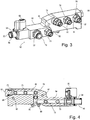
- Fig. 3
- shows one example of the manifold assembly shown in
Fig. 2 . - Fig. 4
- shows a cross sectional view of the manifold assembly shown in
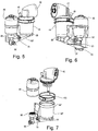
Fig. 4 . - Fig. 5
- shows an integrated manifold assembly with a water filter and hot water assembly attached thereto.
- Fig. 6
- shows the integrated manifold assembly of
Fig. 5 from another angle. - Fig. 7
- shows the integrated manifold assembly of
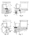
Fig. 5 partially disassembled. - Fig. 8
- shows a side view of the assembly of
Fig. 5 . - Fig. 9
- shows a cross-sectional view taken along line 9-9 of
Fig. 8 including a water flow path through the assembly. - Fig. 10
- shows an end view of the assembly of
Fig. 5 . - Fig. 11
- shows a cross-sectional view taken along line 11-11 of
fig. 10 . - Fig. 12
- shows a diagram of a lavatory water system.
- Fig. 13
- shows one example of a lavatory water system utilizing a manifold assembly.
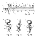
- Fig. 14
- shows a front view of one example of a lavatory water system wherein the manifold is oriented with the fluid conduits oriented vertically.
- Fig. 15
- shows a front view of the example shown in
Fig. 14 . - Fig. 16
- shows an isometric view of the example shown in
Fig. 14 . - Fig. 17
- shows a cutaway view of the manifold component shown in
Fig. 14 . - Fig. 18
- shows a front isometric view of another example with several modifications to the example shown above.
- Fig. 19
- shows a front isometric view of several components which can be attached to the apparatus shown in
Fig. 18 . - Fig. 20
-
Fig. 20 is an optional modification to the apparatus shown inFig. 18 . - Fig. 21
- is a front isometric partially exploded view of the apparatus shown in
Fig. 18 . - Fig. 22
- is an isometric view of the rear portion of the apparatus shown in
Fig. 18 . - Fig. 23
- is a front view of the apparatus shown in
Fig. 18 . - Fig. 24
- is a cutaway view taken along line 24-24 of
Fig. 23 . - Fig. 25
- is a side view of the apparatus shown in
Fig. 18 . - Fig. 26
- is a cutaway view taken along line 26-26 of
Fig. 25 . - Fig. 27
- is a cutaway view taken along line 27-27 of
Fig. 25 . - As is well known, transport category aircraft are generally provided with one or more lavatories for the use by passengers and crew. Such lavatories are very small as the space on all aircraft is at a premium. Although such lavatories generally require a toilet and sink, it is desired that the space for each of these components and all interconnecting components is as small and easily serviced as possible.
- Disclosed herein are several examples of potable lavatory water systems for transport category aircraft, each of which are schematically similar. Generally in prior art assemblies, there is a potable water supply to the laboratory, a shutoff valve, a water filter, a water heater, a check valve, a faucet, and an assorted combination of hoses, tubing, and couplings to connect these components together. These components are typically located under the sink in a cabinet that facilitates access for maintenance.
- The overall potable water system usually also supplies flush water to the toilet assembly for use during flushing. The overall system must also be capable of being drained completely of water for maintenance or cold storage of the aircraft. For ease of use, a gravity drain may be utilized wherein upon opening of a valve, all of the potable water in the distribution system including water in any water filters, water heaters, sink supply line, toilet flush water supply line will drain out of the system. During system draining of such a gravity drain system, the water is drained through the lowest point in the system. Often, a check valve will be provided in the system to protect the water filter by only allowing the water inside of the filter to train through the filter in one direction. All other water in the system bypasses the filter during draining. A schematic of one example of such a system is shown in
Fig. 12 . - To eliminate as many hoses and tubes as possible, reduce overall system size, weight and costs, the manifold system disclosed herein has been developed. Several versions/examples of this apparatus are disclosed herein such as the manifold system shown in
Fig. 3 and the integrated water manifold system shown inFig. 5 and Fig. 6 wherein a mount for a hot water heater and/or water filter are integrated into the manifold body. - The water manifold system combines the fluidic components into one assembly; shutoff valve, check valve, and many of their associated connecting hoses/tubes.
- Although the apparatus can be rotated in a horizontal plane and still function, as shown in
Fig. 1 anaxes system 10 is disclosed including avertical axis 12 pointed in an upwards direction. - As shown in
Fig. 1 , a typical prior art system installation uses a large number of hoses, couplings, and interconnecting structure to distribute water from an aircraft potable water supply system to a sink, toilet, drinking fountain, etc. as desired. As previously mentioned, the space allowance for the overall potable water distribution system within an under sink cabinet (94 ofFig. 12 ) is very constricted.Fig. 1 shows one example of a typical lavatory water system comprising a water supply fitting 96 connected by way of hose (tubing) 24 and another fitting 22 to ashutoff valve 26 which is operated to disconnect the lavatory water system from the aircraft water supply system. One such aircraft fresh water supply system is shown inUS Patent 5,303,739 used herein to reduce the length of this disclosure. To further reduce the length of this disclosure, it is assumed that substantially each hose has a fitting 22 at each end thereof. Thevalve 26 is utilized for example if there is a leak in the lavatory water system to avoid flooding of the aircraft and reduce water waste. Theshutoff valve 26 of this example may be mounted by way ofbracket 28 to the fuselage or fixed internal structure thereof of the aircraft. A T-fitting 30 is coupled to the other side of thevalve 26 with one outlet leading towards atoilet flush coupling 32. The other outlet of the T-fitting 30 in this example leads to a Y-fitting 34. One branch of the Y-fitting 34 diverts flow to acheck valve 36 which prohibits flow there through into a water filter mount 38 but allows for water flow from the water filter mount 38 during a purge. The other branch of the Y-fitting 34 leads to theinlet side 40 of thewater filter 48. Theoutlet 56 of thewater filter 48 leads to theinlet 40 of a water heater. The water heater in this example comprises awater heater element 42 and awater heater reservoir 44. Theoutlet 46 of thewater heater reservoir 44 of this example leads to an electronic faucet controller-thermostat 50. Thisthermostat 50 controls the hot water outlet temperature atoutlet 52 to the sink or other lavatory component. - The
outlet 56 of thewater filter 48 also leads directly to thethermostat 50 so as to provide cold water thereto. Thethermostat 50 also controls the cold water outlet temperature atoutlet 54 to the sink or other lavatory component. - Clearly, in this prior art example, a significant number of interconnecting hoses are required as well as the
couplings 22 utilized on the ends thereof. These hoses and couplings significantly increase the overall vertical dimension 58 of this prior art apparatus. - Looking to
Fig. 2 , is shown an improved or next generationwater manifold system 20. As can be clearly appreciated by comparing this manifold to the apparatus shown inFig. 1 , the overallvertical dimension 60 of thismanifold system 20 is substantially smaller than that of the overall vertical dimension 58 of the apparatus shown inFig. 1 . In this example, awater supply fitting 96 is coupled to the aircraft fresh water supply in the same manner as the previous example. However, the water supply is connected to a water systemmanifold assembly 62 at aninlet 64. Thewater system manifold 62 replacing many of the hoses and couplings shown inFig. 1 to reduce installation costs, saves space, and significantly reduce the overallvertical dimension 60. - Looking to
Fig. 3 is shown this first example of the manifold 62 with a plurality offittings 22 extending therefrom. In the form shown, ashutoff valve 66 is mounted to themanifold body 68 for selective control (flow) of potable water from theinlet 64 to the outlets attached thereto. These outlets comprising anoutlet 70 providing flush water to the toilet, anoutlet 72 to the water filter, aninlet 74 from the water filter to a second fluid conduit, andoutlet 76 to thethermostat 50, and anoutlet 78 to the water heater. In addition, acheck valve 80 having acheck valve cover 82 is fitted into themanifold body 68 to allow for selective passage of water from the firstfluid conduit 84 to the secondfluid conduit 86 as can be appreciated by looking toFig. 4 . O-rings 114 may be utilized between the caps and/or couplings to enhance water retention. In one form, the couplings such ascouplings 22 and others may be formed as a unitary structure with the manifold body. - In addition to the
couplings 22 which may be flareless connections, fixed cavity connections, or other couplings, anauxiliary water outlet 88 may be provided. Thiswater outlet 88 as shown may be used in future applications such as for example a drinking fountain and will also ease in manufacturing of the manifold body as it is aligned with the longitudinal axis of the secondfluid conduit 86. In one form, as shown, theauxiliary water outlet 88 may be closed by way of aremovable plug 90 threaded into the coupling receiver. To utilize this outlet, theplug 90 is removed and acoupling 22 may be attached thereto such as by way of male threads on the coupling fitting into female threads in theoutlet 88. This is one example of how each of thecouplings 22 may be attached to themanifold body 68. - Looking to
Fig. 4 , it can be seen how thepotable water inlet 64 is in fluid communication with the firstfluid conduit 84 when theshutoff valve 66 is in the open position. Thecheck valve 80 prohibits flow directly from the firstfluid conduit 84 to the secondfluid conduit 86 such that the inflow water must either exit throughoutlet 70 to the toilet or throughoutlet 72 to the water filter. When however the system is purged, such as by removing the hose or tubing from the inlet fitting, water is allowed to flow past thecheck valve 80 and out through theinlet 64. This allows for water with in thewater filter 48 to drain without causing a back flow through thewater filter 48 which is not desired. - To facilitate installation, surfaces defining fastener pass-through voids may provide mounting
holes 92 through which fasteners may be attached to removably fasten themanifold assembly 62 to the fuselage of the aircraft such as interior structure of thesink cabinet 94. - In
Fig. 14-17 a second example of the manifold body 68' is shown with similar functionality. This example utilizes a fullyexternal check valve 80 which may also be utilized in the other examples. In this example theauxiliary water outlet 88 is in fluid communication with the firstfluid conduit 84 downstream of the filter. This should be taken into consideration if attached to a drinking fountain for example. - The
manifold body 68 may be formed in several different methods, either machined or molded or combinations thereof. It may also be produced from plastics, metals, or other materials. Four different installations, different sizes and configurations of ports (flared, flare less, fixed cavity, etc.) may be utilized. In addition, themanifold body 68 may be utilized without theshutoff valve 66 attached thereto. In addition, themanifold body 68 is scalable so as to be manufactured with additional ports or different sized ports. For example, looking to the example ofFig. 17 it can be appreciated that there are additional locations wherein ports may be attached to the firstfluid conduit 84 or the secondfluid conduit 86 quite easily. - The disclosed water manifold is also designed to accommodate additional shutoff valve on the opposing and such as at the
auxiliary water outlet 88. This provision permits use in lavatories that have separate water inlets and drain lines to and from the lavatory. For example, the Boeing 777 aircraft and the forward lavatories in the Boeing 737 aircraft have separate water inlets and drain lines to and from the lavatory. In these examples, the water inlet to the lavatory is typically above the lavatory and the drain is the lowest point. In these examples, one valve is the shutoff valve and the other is a drain valve. - One example of the water manifold shown in
Fig. 3 over the integrated water manifold shown inFig. 7 is that the non-integrated water manifold may be easily configured to interface with multiple suppliers water heaters, water filters, and faucet controllers. - The integrated water manifold system shown for example in
Fig. 13 utilizes the same fluid components as shown in the non-integrated manifold and further incorporates a mount for a hot water reservoir 44' and/or a mount for awater filter 48 into themanifold body 68". In the example shown inFig. 7 , thehot water reservoir 44" is formed (cast/molded) as part of themanifold body 68". Aclamp 100 may be utilized to couple theheater element 42 to thehot water reservoir 44" in any of the examples. - In addition, a
filter mount 98 is attached directly to or formed (cast/molded) with themanifold body 68". This example of the manifold body eliminates the need to separately mount and connect those components. Apressure relief valve 102 may also be provided. Acheck valve 80 having acheck valve cap 82 may be utilized as previously disclosed. - In the example shown in
Fig. 13 theshutoff valve 26 is vertically below and remote from thewater inlet 96, separated therefrom by a hose ortubing 104. In this example, the shutoff valve is manipulated by ahandle 106 separated from thevalve 26 viacable 108 which allows remote actuation of thevalve 26. Electronic solenoid valves or other mechanical or electrically operated valves may be utilized. As shown, the shutoff valve has been removed from direct attachment to the manifold in favor of using a remote shutoff valve to minimize hose run lengths, provide flexibility in manifold location, and optimization of shutoff valve location. Looking still toFig. 13 , it can be seen how themanifold body 68" is removably mounted to a mountingbase 110 which is affixed to the aircraft such as to the interior of thesink cabinet 94. In one example, themanifold body 68" is attached to the mountingbase 110 by a quick release system which is designed to be able to be removed from the mountingbase 110 without the use of tools. Looking toFig. 11 , one example of the mounting system utilizes a plurality oftabs 112 which engage tab receivers on the mountingbase 110 shown inFig. 13 . - Looking to
Fig. 18 is shown another example wherein functionally similar components use the same numbering system is that shown in the previous examples. For example, the water filter is shown as 48, the water filter mount is shown as 38. In this example, there are several modifications from that shown in the previous examples. - In the example shown in
Fig. 18 theheating element 42 may incorporate anoutlet module 118. This significantly reduces the overall size of the apparatus. In the cutaway view ofFig. 27 it can be seen how theheating element 42 has aheating coil 116 attached thereto and fitted with in thehot water reservoir 44. - In addition, an
outlet module 118 is shown in fluid communication with thehot water reservoir 44. Theoutlet module 118 has a plurality ofports port 120 and hot water may flow through theport 122 as can be appreciated by looking toFig. 26 and 27 where it is clear that both the hot water and the cold water flow through thewater filter 48 however the cold water conduits bypass theheating coil 116. Looking back toFig. 18 it can be appreciated that theoutlet module 118 may comprise a plurality of release clips 124 which allow for attachment of several modules. Looking toFig. 19 , a manualfaucet interface module 126 is shown comprising a plurality ofoutlets ports manual faucet interface 126 has a plurality ofrelease clip receivers 140 to which the release clips 124 attach. - In
Fig. 19 shows an optional presettemperature faucet controller 132 which says asingular outlet 134 which leads to a sink having a single temperature. As shown, the presettemperature faucet controller 132 as a plurality ofconduits ports temperature faucet controller 132 has similarrelease clip receivers 140 to which the release clips 124 attach. With themanual faucet interface 126, hot water and cold water may be provided to the faucet such that the user can manipulate the faucet to achieve the desired temperature. In the preset temperaturefaucet controller option 132, the user may only be provided with a flow rate control rather than temperature control. -
Fig. 19 shows an adjustable temperaturefaucet controller module 142. This module functions the same or similar to that of the presettemperature faucet controller 132 and that asingular outlet 134 is provided in fluid communication withconduits 136/138 to provide a controlled temperature water flow to the faucet and a single conduit. In this module however, the temperature of the fluid flow may be controlled remotely. - Looking back to
Fig. 19 it can be seen how thewater inlet 64 and water filter 48 portions of the manifold 68'" are connected to the water heater components via acoupling 144. Thiscoupling 144 may allow for removal of the water filter components as shown inFig. 20 wherein thewater inlet 64 is formed of a hose attachment removably attached to a portion of thecoupling 144. - In
Fig. 21 , it can be seen how thewater filter 48 is removably attached to thefilter mount 38 by mail threads provided on the lower end of thefilter 48 screwing into female threads on thefilter mount 38. - In
Fig. 20 1A can also be seen how theheater element 42 attaches to thehot water reservoir 44 in this example by way of aclamp 146. In one form, as previously discussed, thehot water reservoir 44 is a unitary body with themanifold body 68"'. This may be accomplished by way of casting, machining or injection molding. - In
Fig. 24 , a flow path from thewater inlet 64 through thewater filter 48 past thecheck valve 80 is shown. - Looking to
Fig. 22 , another attachment and mechanism is shown wherein aback plate 148 comprises a plurality of keyhole this 150 through whichstuds 152 pass through a larger portion thereof wherein the back plate is repositioned such that the studs engage a smaller portion of thekeyhole 150 thus holding the apparatus in place. Thestuds 152 mounted directly to the lavatory structure such as the interior compartment of the sink. Looking to the bottom region ofFig. 22 , a spring loadedlatch 154 may be utilized to prohibit the manifold 68''' from repositioning in such a way that the back plate comes detached from thestuds 152. This mounting assembly can be used with the previous examples as well. - While the present invention is illustrated by description of several embodiments and while the illustrative embodiments are described in detail, it is not the intention of the applicants to restrict or in any way limit the scope of the appended claims to such detail. Additional advantages and modifications within the scope of the appended claims will readily appear to those sufficed in the art. The invention in its broader aspects is therefore not limited to the specific details, representative apparatus and methods, and illustrative examples shown and described.
Claims (11)
- An aircraft having a lavatory including an Aircraft Lavatory Potable Water System comprising:a. a unitary structure manifold body (68) having;characterized in comprising:i. a plurality of independent internal fluid conduits comprising a first fluid conduit (84) and a second fluid conduit (86),ii. a potable water inlet (64) in fluid communication with the first fluid conduit (84),iii. a water filter outlet (72) in fluid communication with the first fluid conduit (84),iv. a water filter inlet (74) in fluid communication with the second fluid conduit (86),v. a water heater outlet (78) in fluid communication with the second fluid conduit (86),vi. a cold water outlet in fluid communication with the second fluid conduit;
b. a check valve (80) mounted to the manifold body (68) to allow one-way water flow from the second conduit to the first conduit (84) during a purge of the system. - The aircraft as recited in Claim 1 wherein the manifold body (68) further comprises: a shutoff valve (66) in fluid communication between the potable water inlet (64) and the first conduit (84).
- The aircraft as recited in Claim 2 wherein the shutoff valve (66) is a remotely operated valve.
- The aircraft as recited in Claim 1 wherein the filter outlet (72) comprises a filter housing mount (98) directly coupled to the manifold body (68).
- The aircraft as recited in Claim 1 wherein the manifold body (68) further comprises: a toilet water flush outlet in fluid communication with the first fluid conduit.
- The aircraft as recited in Claim 1 wherein the manifold body (68) is formed by a process of injection molding.
- The aircraft as recited in Claim 1 wherein the manifold body (68) comprises fastening brackets attaching the manifold body (68) to a fuselage of the aircraft.
- The aircraft as recited in Claim 1 wherein the system further comprises: a water filter housing and a water filter (48) therein in fluid communication between the water filter outlet (72) and water filter inlet (74).
- The aircraft as recited in Claim 1 wherein each of the potable water inlet (64), water filter outlet (72), water filter inlet (74), water heater outlet (78), and cold water outlet comprises a hose coupling receiver.
- The aircraft as recited in Claim 9 wherein the system further comprises: a hose coupling attached to each of the coupling receivers.
- The aircraft as recited in Claim 1 wherein the system further comprises a water reservoir (44) formed as a unitary structure of the manifold body (68).
Applications Claiming Priority (2)
| Application Number | Priority Date | Filing Date | Title |
|---|---|---|---|
| US201361822984P | 2013-05-14 | 2013-05-14 | |
| PCT/US2014/000120 WO2014185982A1 (en) | 2013-05-14 | 2014-05-14 | Lavatory potable water system |
Publications (3)
| Publication Number | Publication Date |
|---|---|
| EP2997198A1 EP2997198A1 (en) | 2016-03-23 |
| EP2997198A4 EP2997198A4 (en) | 2017-01-11 |
| EP2997198B1 true EP2997198B1 (en) | 2019-07-03 |
Family
ID=51894807
Family Applications (1)
| Application Number | Title | Priority Date | Filing Date |
|---|---|---|---|
| EP14798393.6A Active EP2997198B1 (en) | 2013-05-14 | 2014-05-14 | Lavatory potable water system |
Country Status (4)
| Country | Link |
|---|---|
| US (1) | US9193463B2 (en) |
| EP (1) | EP2997198B1 (en) |
| JP (1) | JP6353033B2 (en) |
| WO (1) | WO2014185982A1 (en) |
Families Citing this family (2)
| Publication number | Priority date | Publication date | Assignee | Title |
|---|---|---|---|---|
| US10829918B2 (en) * | 2019-01-31 | 2020-11-10 | B/E Aerospace, Inc. | Aircraft lavatory touchless manifold system |
| US10864990B2 (en) * | 2019-03-05 | 2020-12-15 | B/E Aerospace, Inc. | Manifold assembly with integrated vent and flow control ports |
Family Cites Families (23)
| Publication number | Priority date | Publication date | Assignee | Title |
|---|---|---|---|---|
| US2336096A (en) * | 1942-12-12 | 1943-12-07 | Jack & Heintz Inc | Mounting frame unit and manifolding for automatic pilot assemblies |
| DE3715759A1 (en) * | 1987-05-12 | 1988-12-01 | Messerschmitt Boelkow Blohm | WATER SUPPLY ARRANGEMENT, IN PARTICULAR ON BOARD A PLANE |
| US5232010A (en) * | 1990-06-05 | 1993-08-03 | Mag Aerospace Industries, Inc. | Drain valve |
| US5303739A (en) * | 1991-09-30 | 1994-04-19 | Deutsche Aerospace Airbus Gmbh | Fresh water supply system for an aircraft |
| US5604938A (en) * | 1992-04-02 | 1997-02-25 | Norcan Aircraft Corporation | Vacuum flush waste disposal system for railcars |
| DE4403067C1 (en) | 1994-02-02 | 1995-04-06 | Deutsche Aerospace Airbus | Device for keeping liquid pipelines, which are open at one end, free of ice |
| US5647269A (en) * | 1994-10-19 | 1997-07-15 | Weber Aircraft | Beverage water heating apparatus for airplanes |
| DE19609939C1 (en) | 1996-03-14 | 1997-09-11 | Daimler Benz Aerospace Airbus | Aircraft water system |
| JP3584754B2 (en) * | 1998-09-28 | 2004-11-04 | 東陶機器株式会社 | Piping equipment |
| JP2001029714A (en) * | 1999-07-23 | 2001-02-06 | Matsushita Electric Ind Co Ltd | Filter |
| JP2002195652A (en) * | 2000-12-27 | 2002-07-10 | Matsushita Electric Ind Co Ltd | Hot water supply apparatus |
| WO2003106003A1 (en) * | 2002-06-12 | 2003-12-24 | The Water System Group, Inc. | Purified water supply system |
| US7299511B2 (en) * | 2004-04-29 | 2007-11-27 | The Boeing Company | Stand up lavatory module |
| US8011033B2 (en) * | 2005-04-08 | 2011-09-06 | The Boeing Company | Aircraft sink with integrated waste disposal function |
| EP1901960B1 (en) * | 2005-06-24 | 2010-05-05 | Mag Aerospace Industries, Inc. | Gray water interface valve systems and methods |
| US8720463B2 (en) * | 2005-12-13 | 2014-05-13 | Airbus Operations Gmbh | Shower system for aircraft |
| US7971603B2 (en) * | 2007-01-26 | 2011-07-05 | Hayward Industries, Inc. | Header for a heat exchanger |
| US8074933B2 (en) * | 2008-02-26 | 2011-12-13 | Goodrich Corporation | Aircraft graywater ejection system |
| EP2342125B1 (en) * | 2008-10-02 | 2014-03-05 | Bombardier Inc. | Shower system for aircraft |
| US9845259B2 (en) * | 2009-01-03 | 2017-12-19 | General Ecology, Inc. | Apparatus for filtering and/or conditioning and/or purifying a fluid such as water |
| DE102009017497A1 (en) * | 2009-04-16 | 2010-10-21 | Airbus Deutschland Gmbh | Water supply module |
| EP2898160A1 (en) * | 2012-09-20 | 2015-07-29 | Zodiac Pool Systems, Inc. | A pool-water heater manifold, a pool-water heater and a method of operating a!pool-water heating system |
| CN105008816B (en) * | 2013-03-11 | 2019-03-08 | 横滨橡胶株式会社 | The faucet device of aircraft washroom unit |
-
2014
- 2014-05-14 US US14/120,349 patent/US9193463B2/en active Active
- 2014-05-14 JP JP2016513947A patent/JP6353033B2/en active Active
- 2014-05-14 WO PCT/US2014/000120 patent/WO2014185982A1/en active Application Filing
- 2014-05-14 EP EP14798393.6A patent/EP2997198B1/en active Active
Non-Patent Citations (1)
| Title |
|---|
| None * |
Also Published As
| Publication number | Publication date |
|---|---|
| JP2016525976A (en) | 2016-09-01 |
| EP2997198A1 (en) | 2016-03-23 |
| US9193463B2 (en) | 2015-11-24 |
| WO2014185982A1 (en) | 2014-11-20 |
| US20140338766A1 (en) | 2014-11-20 |
| EP2997198A4 (en) | 2017-01-11 |
| JP6353033B2 (en) | 2018-07-04 |
Similar Documents
| Publication | Publication Date | Title |
|---|---|---|
| US7077153B2 (en) | Side control faucet with diverter assembly | |
| CA2539958C (en) | Isolation valve with valve in drain | |
| US7621295B2 (en) | System for controlling fluid flow to an appliance | |
| CA2644217C (en) | Faucet mounting system including a lift rod | |
| CN104837729A (en) | Aircraft galley plumbing system and potable water filter and distribution mounting manifold therefore | |
| EP2997198B1 (en) | Lavatory potable water system | |
| GB2509714A (en) | Plumbing diverter component | |
| US20100224266A1 (en) | Connecting unit for sanitary fittings | |
| CA2968559A1 (en) | Faucet assembly including a thermostatic mixing cartridge | |
| US6969462B2 (en) | Pipe mounting apparatus for water filter | |
| DK171001B1 (en) | Mixing luminaire as well as a base for it | |
| CN101160437A (en) | Faucet assembly with integral water supply shut-off valve | |
| EP1828652B1 (en) | Universal fluid valve body | |
| EP2917646B1 (en) | A heating radiator of a heating system, the radiator comprising two heating plates and a connecting element connecting the two heating plates | |
| EP2921791A1 (en) | System for recirculating water between cold water and hot water pipes | |
| NL2015440B1 (en) | Satellite for central heating or for teleheating with multifunction presettings. | |
| JP2016525976A5 (en) | ||
| KR102661752B1 (en) | Water purifier | |
| AU2008200922B2 (en) | Valve unit | |
| KR20220085318A (en) | Water purifier | |
| SE506367C2 (en) | Inlet part of a valve | |
| CN114096717A (en) | Lavatory basin mounting assembly and method for assembling lavatory basin mounting assembly | |
| KR200418355Y1 (en) | Pump connection piping structure | |
| CN113251181A (en) | Four-in-one faucet system | |
| WO2009058632A1 (en) | Hot/cold fluid isolation valve |
Legal Events
| Date | Code | Title | Description |
|---|---|---|---|
| PUAI | Public reference made under article 153(3) epc to a published international application that has entered the european phase |
Free format text: ORIGINAL CODE: 0009012 |
|
| 17P | Request for examination filed |
Effective date: 20151104 |
|
| AK | Designated contracting states |
Kind code of ref document: A1 Designated state(s): AL AT BE BG CH CY CZ DE DK EE ES FI FR GB GR HR HU IE IS IT LI LT LU LV MC MK MT NL NO PL PT RO RS SE SI SK SM TR |
|
| AX | Request for extension of the european patent |
Extension state: BA ME |
|
| DAX | Request for extension of the european patent (deleted) | ||
| A4 | Supplementary search report drawn up and despatched |
Effective date: 20161213 |
|
| RIC1 | Information provided on ipc code assigned before grant |
Ipc: B64D 11/02 20060101ALI20161207BHEP Ipc: E03B 7/07 20060101AFI20161207BHEP |
|
| RAP1 | Party data changed (applicant data changed or rights of an application transferred) |
Owner name: C&D ZODIAC, INC. |
|
| GRAP | Despatch of communication of intention to grant a patent |
Free format text: ORIGINAL CODE: EPIDOSNIGR1 |
|
| STAA | Information on the status of an ep patent application or granted ep patent |
Free format text: STATUS: GRANT OF PATENT IS INTENDED |
|
| INTG | Intention to grant announced |
Effective date: 20190118 |
|
| GRAS | Grant fee paid |
Free format text: ORIGINAL CODE: EPIDOSNIGR3 |
|
| GRAA | (expected) grant |
Free format text: ORIGINAL CODE: 0009210 |
|
| STAA | Information on the status of an ep patent application or granted ep patent |
Free format text: STATUS: THE PATENT HAS BEEN GRANTED |
|
| AK | Designated contracting states |
Kind code of ref document: B1 Designated state(s): AL AT BE BG CH CY CZ DE DK EE ES FI FR GB GR HR HU IE IS IT LI LT LU LV MC MK MT NL NO PL PT RO RS SE SI SK SM TR |
|
| REG | Reference to a national code |
Ref country code: GB Ref legal event code: FG4D |
|
| REG | Reference to a national code |
Ref country code: CH Ref legal event code: EP Ref country code: AT Ref legal event code: REF Ref document number: 1151159 Country of ref document: AT Kind code of ref document: T Effective date: 20190715 |
|
| REG | Reference to a national code |
Ref country code: DE Ref legal event code: R096 Ref document number: 602014049551 Country of ref document: DE |
|
| REG | Reference to a national code |
Ref country code: IE Ref legal event code: FG4D |
|
| REG | Reference to a national code |
Ref country code: NL Ref legal event code: MP Effective date: 20190703 |
|
| REG | Reference to a national code |
Ref country code: LT Ref legal event code: MG4D |
|
| REG | Reference to a national code |
Ref country code: AT Ref legal event code: MK05 Ref document number: 1151159 Country of ref document: AT Kind code of ref document: T Effective date: 20190703 |
|
| PG25 | Lapsed in a contracting state [announced via postgrant information from national office to epo] |
Ref country code: AT Free format text: LAPSE BECAUSE OF FAILURE TO SUBMIT A TRANSLATION OF THE DESCRIPTION OR TO PAY THE FEE WITHIN THE PRESCRIBED TIME-LIMIT Effective date: 20190703 Ref country code: BG Free format text: LAPSE BECAUSE OF FAILURE TO SUBMIT A TRANSLATION OF THE DESCRIPTION OR TO PAY THE FEE WITHIN THE PRESCRIBED TIME-LIMIT Effective date: 20191003 Ref country code: SE Free format text: LAPSE BECAUSE OF FAILURE TO SUBMIT A TRANSLATION OF THE DESCRIPTION OR TO PAY THE FEE WITHIN THE PRESCRIBED TIME-LIMIT Effective date: 20190703 Ref country code: NL Free format text: LAPSE BECAUSE OF FAILURE TO SUBMIT A TRANSLATION OF THE DESCRIPTION OR TO PAY THE FEE WITHIN THE PRESCRIBED TIME-LIMIT Effective date: 20190703 Ref country code: PT Free format text: LAPSE BECAUSE OF FAILURE TO SUBMIT A TRANSLATION OF THE DESCRIPTION OR TO PAY THE FEE WITHIN THE PRESCRIBED TIME-LIMIT Effective date: 20191104 Ref country code: HR Free format text: LAPSE BECAUSE OF FAILURE TO SUBMIT A TRANSLATION OF THE DESCRIPTION OR TO PAY THE FEE WITHIN THE PRESCRIBED TIME-LIMIT Effective date: 20190703 Ref country code: LT Free format text: LAPSE BECAUSE OF FAILURE TO SUBMIT A TRANSLATION OF THE DESCRIPTION OR TO PAY THE FEE WITHIN THE PRESCRIBED TIME-LIMIT Effective date: 20190703 Ref country code: CZ Free format text: LAPSE BECAUSE OF FAILURE TO SUBMIT A TRANSLATION OF THE DESCRIPTION OR TO PAY THE FEE WITHIN THE PRESCRIBED TIME-LIMIT Effective date: 20190703 Ref country code: FI Free format text: LAPSE BECAUSE OF FAILURE TO SUBMIT A TRANSLATION OF THE DESCRIPTION OR TO PAY THE FEE WITHIN THE PRESCRIBED TIME-LIMIT Effective date: 20190703 Ref country code: NO Free format text: LAPSE BECAUSE OF FAILURE TO SUBMIT A TRANSLATION OF THE DESCRIPTION OR TO PAY THE FEE WITHIN THE PRESCRIBED TIME-LIMIT Effective date: 20191003 |
|
| PG25 | Lapsed in a contracting state [announced via postgrant information from national office to epo] |
Ref country code: LV Free format text: LAPSE BECAUSE OF FAILURE TO SUBMIT A TRANSLATION OF THE DESCRIPTION OR TO PAY THE FEE WITHIN THE PRESCRIBED TIME-LIMIT Effective date: 20190703 Ref country code: GR Free format text: LAPSE BECAUSE OF FAILURE TO SUBMIT A TRANSLATION OF THE DESCRIPTION OR TO PAY THE FEE WITHIN THE PRESCRIBED TIME-LIMIT Effective date: 20191004 Ref country code: RS Free format text: LAPSE BECAUSE OF FAILURE TO SUBMIT A TRANSLATION OF THE DESCRIPTION OR TO PAY THE FEE WITHIN THE PRESCRIBED TIME-LIMIT Effective date: 20190703 Ref country code: IS Free format text: LAPSE BECAUSE OF FAILURE TO SUBMIT A TRANSLATION OF THE DESCRIPTION OR TO PAY THE FEE WITHIN THE PRESCRIBED TIME-LIMIT Effective date: 20191103 Ref country code: ES Free format text: LAPSE BECAUSE OF FAILURE TO SUBMIT A TRANSLATION OF THE DESCRIPTION OR TO PAY THE FEE WITHIN THE PRESCRIBED TIME-LIMIT Effective date: 20190703 Ref country code: AL Free format text: LAPSE BECAUSE OF FAILURE TO SUBMIT A TRANSLATION OF THE DESCRIPTION OR TO PAY THE FEE WITHIN THE PRESCRIBED TIME-LIMIT Effective date: 20190703 |
|
| PG25 | Lapsed in a contracting state [announced via postgrant information from national office to epo] |
Ref country code: TR Free format text: LAPSE BECAUSE OF FAILURE TO SUBMIT A TRANSLATION OF THE DESCRIPTION OR TO PAY THE FEE WITHIN THE PRESCRIBED TIME-LIMIT Effective date: 20190703 |
|
| PG25 | Lapsed in a contracting state [announced via postgrant information from national office to epo] |
Ref country code: DK Free format text: LAPSE BECAUSE OF FAILURE TO SUBMIT A TRANSLATION OF THE DESCRIPTION OR TO PAY THE FEE WITHIN THE PRESCRIBED TIME-LIMIT Effective date: 20190703 Ref country code: IT Free format text: LAPSE BECAUSE OF FAILURE TO SUBMIT A TRANSLATION OF THE DESCRIPTION OR TO PAY THE FEE WITHIN THE PRESCRIBED TIME-LIMIT Effective date: 20190703 Ref country code: EE Free format text: LAPSE BECAUSE OF FAILURE TO SUBMIT A TRANSLATION OF THE DESCRIPTION OR TO PAY THE FEE WITHIN THE PRESCRIBED TIME-LIMIT Effective date: 20190703 Ref country code: RO Free format text: LAPSE BECAUSE OF FAILURE TO SUBMIT A TRANSLATION OF THE DESCRIPTION OR TO PAY THE FEE WITHIN THE PRESCRIBED TIME-LIMIT Effective date: 20190703 Ref country code: PL Free format text: LAPSE BECAUSE OF FAILURE TO SUBMIT A TRANSLATION OF THE DESCRIPTION OR TO PAY THE FEE WITHIN THE PRESCRIBED TIME-LIMIT Effective date: 20190703 |
|
| PG25 | Lapsed in a contracting state [announced via postgrant information from national office to epo] |
Ref country code: SK Free format text: LAPSE BECAUSE OF FAILURE TO SUBMIT A TRANSLATION OF THE DESCRIPTION OR TO PAY THE FEE WITHIN THE PRESCRIBED TIME-LIMIT Effective date: 20190703 Ref country code: SM Free format text: LAPSE BECAUSE OF FAILURE TO SUBMIT A TRANSLATION OF THE DESCRIPTION OR TO PAY THE FEE WITHIN THE PRESCRIBED TIME-LIMIT Effective date: 20190703 Ref country code: IS Free format text: LAPSE BECAUSE OF FAILURE TO SUBMIT A TRANSLATION OF THE DESCRIPTION OR TO PAY THE FEE WITHIN THE PRESCRIBED TIME-LIMIT Effective date: 20200224 |
|
| REG | Reference to a national code |
Ref country code: DE Ref legal event code: R097 Ref document number: 602014049551 Country of ref document: DE |
|
| PLBE | No opposition filed within time limit |
Free format text: ORIGINAL CODE: 0009261 |
|
| STAA | Information on the status of an ep patent application or granted ep patent |
Free format text: STATUS: NO OPPOSITION FILED WITHIN TIME LIMIT |
|
| PG2D | Information on lapse in contracting state deleted |
Ref country code: IS |
|
| 26N | No opposition filed |
Effective date: 20200603 |
|
| PG25 | Lapsed in a contracting state [announced via postgrant information from national office to epo] |
Ref country code: SI Free format text: LAPSE BECAUSE OF FAILURE TO SUBMIT A TRANSLATION OF THE DESCRIPTION OR TO PAY THE FEE WITHIN THE PRESCRIBED TIME-LIMIT Effective date: 20190703 |
|
| PG25 | Lapsed in a contracting state [announced via postgrant information from national office to epo] |
Ref country code: CH Free format text: LAPSE BECAUSE OF NON-PAYMENT OF DUE FEES Effective date: 20200531 Ref country code: MC Free format text: LAPSE BECAUSE OF FAILURE TO SUBMIT A TRANSLATION OF THE DESCRIPTION OR TO PAY THE FEE WITHIN THE PRESCRIBED TIME-LIMIT Effective date: 20190703 Ref country code: LI Free format text: LAPSE BECAUSE OF NON-PAYMENT OF DUE FEES Effective date: 20200531 |
|
| REG | Reference to a national code |
Ref country code: BE Ref legal event code: MM Effective date: 20200531 |
|
| GBPC | Gb: european patent ceased through non-payment of renewal fee |
Effective date: 20200514 |
|
| PG25 | Lapsed in a contracting state [announced via postgrant information from national office to epo] |
Ref country code: LU Free format text: LAPSE BECAUSE OF NON-PAYMENT OF DUE FEES Effective date: 20200514 |
|
| PG25 | Lapsed in a contracting state [announced via postgrant information from national office to epo] |
Ref country code: GB Free format text: LAPSE BECAUSE OF NON-PAYMENT OF DUE FEES Effective date: 20200514 Ref country code: IE Free format text: LAPSE BECAUSE OF NON-PAYMENT OF DUE FEES Effective date: 20200514 |
|
| PG25 | Lapsed in a contracting state [announced via postgrant information from national office to epo] |
Ref country code: BE Free format text: LAPSE BECAUSE OF NON-PAYMENT OF DUE FEES Effective date: 20200531 |
|
| PG25 | Lapsed in a contracting state [announced via postgrant information from national office to epo] |
Ref country code: MT Free format text: LAPSE BECAUSE OF FAILURE TO SUBMIT A TRANSLATION OF THE DESCRIPTION OR TO PAY THE FEE WITHIN THE PRESCRIBED TIME-LIMIT Effective date: 20190703 Ref country code: CY Free format text: LAPSE BECAUSE OF FAILURE TO SUBMIT A TRANSLATION OF THE DESCRIPTION OR TO PAY THE FEE WITHIN THE PRESCRIBED TIME-LIMIT Effective date: 20190703 |
|
| PG25 | Lapsed in a contracting state [announced via postgrant information from national office to epo] |
Ref country code: MK Free format text: LAPSE BECAUSE OF FAILURE TO SUBMIT A TRANSLATION OF THE DESCRIPTION OR TO PAY THE FEE WITHIN THE PRESCRIBED TIME-LIMIT Effective date: 20190703 |
|
| REG | Reference to a national code |
Ref country code: DE Ref legal event code: R081 Ref document number: 602014049551 Country of ref document: DE Owner name: SAFRAN CABIN INC. (N.D.GES.D. STAATES DELAWARE, US Free format text: FORMER OWNER: C&D ZODIAC, INC., HUNTINGTON BEACH, CALIF., US |
|
| PGFP | Annual fee paid to national office [announced via postgrant information from national office to epo] |
Ref country code: FR Payment date: 20230420 Year of fee payment: 10 Ref country code: DE Payment date: 20230419 Year of fee payment: 10 |