EP2996276B1 - Gestaltung eines dl-backhaul-steuerkanals für relais - Google Patents
Gestaltung eines dl-backhaul-steuerkanals für relais Download PDFInfo
- Publication number
- EP2996276B1 EP2996276B1 EP15189998.6A EP15189998A EP2996276B1 EP 2996276 B1 EP2996276 B1 EP 2996276B1 EP 15189998 A EP15189998 A EP 15189998A EP 2996276 B1 EP2996276 B1 EP 2996276B1
- Authority
- EP
- European Patent Office
- Prior art keywords
- pdcch
- ofdm
- bits
- relay
- subframe
- Prior art date
- Legal status (The legal status is an assumption and is not a legal conclusion. Google has not performed a legal analysis and makes no representation as to the accuracy of the status listed.)
- Active
Links
- 238000013461 design Methods 0.000 title description 5
- 238000000034 method Methods 0.000 claims description 40
- 230000005540 biological transmission Effects 0.000 claims description 25
- 238000013468 resource allocation Methods 0.000 claims description 25
- 238000013507 mapping Methods 0.000 description 36
- 238000004891 communication Methods 0.000 description 25
- 238000005516 engineering process Methods 0.000 description 18
- 239000013598 vector Substances 0.000 description 15
- 230000006870 function Effects 0.000 description 12
- 230000011664 signaling Effects 0.000 description 11
- 241000700159 Rattus Species 0.000 description 8
- 238000010586 diagram Methods 0.000 description 7
- 101000741965 Homo sapiens Inactive tyrosine-protein kinase PRAG1 Proteins 0.000 description 5
- 102100038659 Inactive tyrosine-protein kinase PRAG1 Human genes 0.000 description 5
- 230000002776 aggregation Effects 0.000 description 5
- 238000004220 aggregation Methods 0.000 description 5
- 241000760358 Enodes Species 0.000 description 4
- 230000004913 activation Effects 0.000 description 4
- 238000012545 processing Methods 0.000 description 4
- 101150084062 RAN gene Proteins 0.000 description 3
- 230000008901 benefit Effects 0.000 description 3
- 230000001413 cellular effect Effects 0.000 description 3
- 230000002093 peripheral effect Effects 0.000 description 3
- 101150039363 SIB2 gene Proteins 0.000 description 2
- 230000009849 deactivation Effects 0.000 description 2
- 229910001416 lithium ion Inorganic materials 0.000 description 2
- 230000007774 longterm Effects 0.000 description 2
- 238000007726 management method Methods 0.000 description 2
- QELJHCBNGDEXLD-UHFFFAOYSA-N nickel zinc Chemical compound [Ni].[Zn] QELJHCBNGDEXLD-UHFFFAOYSA-N 0.000 description 2
- 230000008569 process Effects 0.000 description 2
- 230000009467 reduction Effects 0.000 description 2
- 230000004044 response Effects 0.000 description 2
- 238000000638 solvent extraction Methods 0.000 description 2
- 238000001228 spectrum Methods 0.000 description 2
- HBBGRARXTFLTSG-UHFFFAOYSA-N Lithium ion Chemical compound [Li+] HBBGRARXTFLTSG-UHFFFAOYSA-N 0.000 description 1
- 235000010627 Phaseolus vulgaris Nutrition 0.000 description 1
- 244000046052 Phaseolus vulgaris Species 0.000 description 1
- 101150069124 RAN1 gene Proteins 0.000 description 1
- 101100355633 Salmo salar ran gene Proteins 0.000 description 1
- 238000007792 addition Methods 0.000 description 1
- 238000004873 anchoring Methods 0.000 description 1
- OJIJEKBXJYRIBZ-UHFFFAOYSA-N cadmium nickel Chemical compound [Ni].[Cd] OJIJEKBXJYRIBZ-UHFFFAOYSA-N 0.000 description 1
- 239000000969 carrier Substances 0.000 description 1
- 230000008859 change Effects 0.000 description 1
- 238000004590 computer program Methods 0.000 description 1
- 230000003247 decreasing effect Effects 0.000 description 1
- 230000009977 dual effect Effects 0.000 description 1
- 239000000446 fuel Substances 0.000 description 1
- 238000003780 insertion Methods 0.000 description 1
- 230000037431 insertion Effects 0.000 description 1
- 239000004973 liquid crystal related substance Substances 0.000 description 1
- 230000005055 memory storage Effects 0.000 description 1
- 229910052987 metal hydride Inorganic materials 0.000 description 1
- 238000010295 mobile communication Methods 0.000 description 1
- 229910052759 nickel Inorganic materials 0.000 description 1
- PXHVJJICTQNCMI-UHFFFAOYSA-N nickel Substances [Ni] PXHVJJICTQNCMI-UHFFFAOYSA-N 0.000 description 1
- -1 nickel metal hydride Chemical class 0.000 description 1
- 230000003287 optical effect Effects 0.000 description 1
- 238000005192 partition Methods 0.000 description 1
- 239000004065 semiconductor Substances 0.000 description 1
- 230000007704 transition Effects 0.000 description 1
Images


Classifications
-
- H—ELECTRICITY
- H04—ELECTRIC COMMUNICATION TECHNIQUE
- H04W—WIRELESS COMMUNICATION NETWORKS
- H04W40/00—Communication routing or communication path finding
- H04W40/02—Communication route or path selection, e.g. power-based or shortest path routing
- H04W40/22—Communication route or path selection, e.g. power-based or shortest path routing using selective relaying for reaching a BTS [Base Transceiver Station] or an access point
-
- H—ELECTRICITY
- H04—ELECTRIC COMMUNICATION TECHNIQUE
- H04B—TRANSMISSION
- H04B7/00—Radio transmission systems, i.e. using radiation field
- H04B7/14—Relay systems
- H04B7/15—Active relay systems
- H04B7/155—Ground-based stations
-
- H—ELECTRICITY
- H04—ELECTRIC COMMUNICATION TECHNIQUE
- H04L—TRANSMISSION OF DIGITAL INFORMATION, e.g. TELEGRAPHIC COMMUNICATION
- H04L27/00—Modulated-carrier systems
- H04L27/26—Systems using multi-frequency codes
-
- H—ELECTRICITY
- H04—ELECTRIC COMMUNICATION TECHNIQUE
- H04B—TRANSMISSION
- H04B7/00—Radio transmission systems, i.e. using radiation field
- H04B7/14—Relay systems
-
- H—ELECTRICITY
- H04—ELECTRIC COMMUNICATION TECHNIQUE
- H04L—TRANSMISSION OF DIGITAL INFORMATION, e.g. TELEGRAPHIC COMMUNICATION
- H04L5/00—Arrangements affording multiple use of the transmission path
- H04L5/003—Arrangements for allocating sub-channels of the transmission path
- H04L5/0053—Allocation of signaling, i.e. of overhead other than pilot signals
-
- H—ELECTRICITY
- H04—ELECTRIC COMMUNICATION TECHNIQUE
- H04L—TRANSMISSION OF DIGITAL INFORMATION, e.g. TELEGRAPHIC COMMUNICATION
- H04L5/00—Arrangements affording multiple use of the transmission path
- H04L5/0091—Signaling for the administration of the divided path
- H04L5/0094—Indication of how sub-channels of the path are allocated
-
- H—ELECTRICITY
- H04—ELECTRIC COMMUNICATION TECHNIQUE
- H04W—WIRELESS COMMUNICATION NETWORKS
- H04W68/00—User notification, e.g. alerting and paging, for incoming communication, change of service or the like
- H04W68/02—Arrangements for increasing efficiency of notification or paging channel
-
- H—ELECTRICITY
- H04—ELECTRIC COMMUNICATION TECHNIQUE
- H04W—WIRELESS COMMUNICATION NETWORKS
- H04W72/00—Local resource management
- H04W72/20—Control channels or signalling for resource management
- H04W72/23—Control channels or signalling for resource management in the downlink direction of a wireless link, i.e. towards a terminal
-
- H—ELECTRICITY
- H04—ELECTRIC COMMUNICATION TECHNIQUE
- H04W—WIRELESS COMMUNICATION NETWORKS
- H04W88/00—Devices specially adapted for wireless communication networks, e.g. terminals, base stations or access point devices
- H04W88/02—Terminal devices
- H04W88/04—Terminal devices adapted for relaying to or from another terminal or user
-
- H—ELECTRICITY
- H04—ELECTRIC COMMUNICATION TECHNIQUE
- H04W—WIRELESS COMMUNICATION NETWORKS
- H04W72/00—Local resource management
- H04W72/04—Wireless resource allocation
-
- H—ELECTRICITY
- H04—ELECTRIC COMMUNICATION TECHNIQUE
- H04W—WIRELESS COMMUNICATION NETWORKS
- H04W72/00—Local resource management
- H04W72/20—Control channels or signalling for resource management
-
- H—ELECTRICITY
- H04—ELECTRIC COMMUNICATION TECHNIQUE
- H04W—WIRELESS COMMUNICATION NETWORKS
- H04W84/00—Network topologies
- H04W84/02—Hierarchically pre-organised networks, e.g. paging networks, cellular networks, WLAN [Wireless Local Area Network] or WLL [Wireless Local Loop]
- H04W84/04—Large scale networks; Deep hierarchical networks
- H04W84/042—Public Land Mobile systems, e.g. cellular systems
- H04W84/047—Public Land Mobile systems, e.g. cellular systems using dedicated repeater stations
Definitions
- a type I relay may be included as one of the technology components for LTE-A.
- a type I relay creates new cells, distinguishable and separate from the cells of a donor eNodeB (eNB).
- eNB donor eNodeB
- WTRU wireless transmit/receive unit
- a type I relay node (RN) may be described as an eNB that has a wireless in-band backhaul link back to the donor eNB by using an LTE or LTE-A air interface within the international mobile telecommunications (IMT) spectrum allocation.
- IMT international mobile telecommunications
- a method and an apparatus for communication supporting dual cell high speed downlink packet access, DC-HSDPA, for use in a wireless transmit/receive unit, WTRU is disclosed.
- a WTRU receiving, via an anchor carrier or a supplementary carrier, a first high speed shared control channel, HS-SCCH, order indicating activation of discontinuous reception, DRX message.
- DRX discontinuous reception
- DRX discontinuous reception
- the performing DRX includes applying a same DRX pattern to both the anchor carrier and the at least one supplementary carrier in response to the first HS-SCCH order such that DRX cycles of the anchor carrier and the supplementary carrier are aligned in the DRX pattern.
- the activation of DRX is common to both the anchor carrier and the supplementary carrier.
- the WTRU may further be receiving a second HS-SCCH order indicating deactivation of DRX for at least one of the anchor carrier or the supplementary carrier.
- the WTRU may further be deactivating DRX on both the anchor carrier and the supplementary carrier in response to the second HS-SCCH order.
- Methods and apparatus are described for providing compatible mapping for backhaul control channels, frequency first mapping of control channel elements (CCEs) and tree based relay resource allocation.
- Methods and apparatus for mapping of control signals such as Un downlink (DL) control signals, between a base station (e.g ., eNB) and a relay node (e.g ., type I relay node) are described. This includes time-frequeney mapping of the control signals into RBs of MBSFN-reserved sub-frames in the RN cell and encoding procedures.
- DL Un downlink
- Control Structure for Relay Type 1 nodes Examples of prior art may be found in a document entitled " Control Structure for Relay Type 1 nodes" from the NEC group.
- the document is a 3GPP draft; R1-092965 control structure for relay type 1 nodes-updated, 3rd generation partnership project, 3GPP, mobile competence centre; 650, route des lucioles; F-06921 sophia-antipolis cedex; France, no. Los Angeles, USA; 20090707, 7 July 2009 (2009-07-07 ).
- FIG. 1A is a diagram of an example communications system 100 in which one or more disclosed embodiments may be implemented.
- the communications system 100 may be a multiple access system that provides content, such as voice, data, video, messagins, broadcast, etc., to multiple wireless users.
- the communications system 100 may enable multiple wireless users to access such content through the sharing of system resources, including wireless bandwidth.
- the communications systems 100 may employ one or more channel access methods, such as code division multiple access (CDMA), time division multiple access (TDMA), frequency division multiple access (FDMA), orthogonal FDMA (OFDMA), single-carrier FDMA (SC-FDMA), and the like.
- CDMA code division multiple access
- TDMA time division multiple access
- FDMA frequency division multiple access
- OFDMA orthogonal FDMA
- SC-FDMA single-carrier FDMA
- the communications system 100 may include wireless transmit/receive units (WTRUs) 102a, 102b, 102c, 102d, a radio access network (RAN) 104, a core network 106, a public switched telephone network (PSTN) 108, the Internet 110, and other networks 112, though it will be appreciated that the disclosed embodiments contemplate any number of WTRUs, base stations, networks, and/or network elements.
- WTRUs 102a, 102b, 102c, 102d may be any type of device configured to operate and/or communicate in a. wireless environment.
- the WTRUs 1052a, 102b, 102c, 102d may be configured to transmit and/or receive wireless signals and may include user equipment (UE), a mobile station, a fixed or mobile subscriber unit, a pager, a cellular telephone, a personal digital assistant (PDA), a smartphone, a laptop, a netbook, a personal computer, a wireless sensor, consumer electronics, and the like.
- UE user equipment
- PDA personal digital assistant
- smartphone a laptop
- netbook a personal computer
- a wireless sensor consumer electronics, and the like.
- the communications systems 100 may also include a base station 114a and a base station 114b.
- Each of the base stations 114a, 114b may be any type of device configured to wirelessly interface with at least one of the WTRUs 102a, 102b, 102c, 102d to facilitate access to one or more cammunication networks, such as the core network 106, the Internet 110, and/or the networks 112.
- the base stations 114a, 114b may be a base transceiver station (BTS), a Node-B, an eNode B, a Home Node B, a Home eNode B, a site controller, an access point (AP), a wireless router, and the like. While the base stations 114a, 114b are each depicted as a single element, it will be appreciated that the base stations 114a, 1144 may include any number of interconnected base stations and/or network elements..
- the base station 114a may be part of ihe RAN 104, which may also include other base stations and/or network elements (not shown), such as a base station controller (BSC), a radio network controller (RNC), relay nodes, etc.
- BSC base station controller
- RNC radio network controller
- the base station 114a and/or the base station 114b may be configured to transmit and/or receive wireless signals within a particular geographic region, which may be referred to as a cell (not shown).
- the cell may further be divided into cell sectors.
- the cell associated with the base station 114a may be divided into three sectors.
- the base station 114a may include three transceivers, i.e., one for each sector of the cell.
- the base station 114a may employ multiple-input multiple output (MIMO) technology and, therefore, may utilize multiple transceivers for each sector of the cell.
- MIMO multiple-input multiple output
- the base stations 114a, 114b may communicate with one or more of the WTRUs 102a, 102b, 102c. 102d over an air interface 116, which may be any suitable wireless communication link (e.g., radio frequency (RF), microwave, infrared (IR), ultraviolet (UV), visible light, etc.).
- the air interface 116 may be established using any suitable radio access technology. (RAT).
- RAT radio access technology
- the communications system 100 may be a multiple access system and may employ one or more channel access schemes, such as CDMA, TDMA, FDMA, OFDMA, SC-FDMA, and the like.
- the base station 114a in the RAN 104 and the WTRUs 102a, 102b, 102c may implement a radio technology such as Universal Mobile Telecommunications System (UWS) Terrestrial Radio Access (UTRA), which may establish the air interface 116 using wideband CDMA (WCDMA).
- WCDMA may include communication protocols such as High-Speed Packet Access (HSPA) and/or Evolved HSPA (HSPA+).
- HSPA may include High-Speed Downlink Packet Access (HSDPA) and/or High-Speed Uplink Packet Access (HSUPA).
- the base station 114a and the WTRUs 102a, 102b, 102e may implement a radio technology such as Evolved UMTS Terrestrial Radio Access (E-UTRA), which may establish the air interlace 116 using Long Term Evolution (LTE) and/or LTE-Advanced (LTF-A).
- E-UTRA Evolved UMTS Terrestrial Radio Access
- LTE Long Term Evolution
- LTF-A LTE-Advanced
- the base station 114a and the WTRUs 102a, 102b, 102c may implement radio technologies such as IEEE 802.16 (i.e., Worldwide Interoperability for Microwave Access (WiMAX)), CDMA2000, CDMA2000 1X, CDMA2000 EV-DO, Interim Standard 2000 (IS-2000), Interim Standard 95 (IS-95), Interim Standard 856 (IS-856), Global System for Mobile communications (GSM), Enhanced Data rates for GSM Evolution (EDGE), GSM EDGE (GERAN), and the like.
- IEEE 802.16 i.e., Worldwide Interoperability for Microwave Access (WiMAX)
- CDMA2000, CDMA2000 1X, CDMA2000 EV-DO Code Division Multiple Access 2000
- IS-95 Interim Standard 95
- IS-856 Interim Standard 856
- GSM Global System for Mobile communications
- GSM Global System for Mobile communications
- EDGE Enhanced Data rates for GSM Evolution
- GERAN GSM EDGERAN
- the base station 114b in FIG. 1A may be a wireless router, Home Node B, Home eNode B, or access point, for example, and may utilize any suitable RAT for facilitating wireless connectivity in a localized area, such as a place of business, a home, a vehicle, a campus, and the like.
- the base station 114b and the WTRUs 102c, 102d may implement a radio technology, such as IEEE 802.11 to establish a wireless local area network (WLAN).
- the base station 114b and the WTRUs 102c, 102d may implement a radio technology such as IEEE 802.15 to establish a wireless perianal area network (WPAN).
- WPAN wireless perianal area network
- the base station 114b and the WTRUs 102c, 102d may utilize a cellular-based RAT (e.g., WCDMA, CDMA2000, GSM, LTE, LTE-A, etc.) to establish a picocell or femtocell.
- a cellular-based RAT e.g., WCDMA, CDMA2000, GSM, LTE, LTE-A, etc.
- the base-station 114b may have a direct connection to the Internet 110.
- the base station 114b may not be required to access the Internet 110 via the core network 106.
- the RAN 104 may be in communication with the core network 106, which may be any type of network configured to provide voice, data, applications, and/or voice over internet protocol (VoIP) services to one or more of the WTRUS 102a, 102b, 102c, 102d.
- the core network 106 may provide call control, billing services, mobile location-based services, pre-paid calling, Internet connectivity, video distribution, etc., and/or perform high-level security functions, such as user authentication.
- the RAN 104 and/or the core network 106 may be in direct or indirect communication with other RANs that employ the same RAT as the RAN 104 or a different RAT.
- the core network 106 may also be in communication with another RAN (not shown) employing a GSM radio technology.
- the core network 106 may also serve as a gateway for the WTKUs 102a, 102-b, 102c, 102d to access the PSTN 108, the Internet 110, and/or other networks 112.
- the PSTN 108 may include circuit-switched telephone networks that provide plain old telephone service (POTS).
- POTS plain old telephone service
- the Internet 110 may include a global system of interconnected computer networks and devices that use common communication protocols, such as the transmission control protocol (TCP), user datagram protocol (UDP) and the internet protocol (TP) in the TCP/IP internet protocol suite.
- the networks 112 may include wired or wireless communications networks owned and/or operated by other service providers.
- the networks 112 may include another core network connected to one or more RANs, which may employ the same RAT as the RAN 104 or a different RAT.
- the WTRUs 102a, 102b, 102c, 102d in the communications system 100 may include multi-mode capabilities, i.e., the WTRUs 102a, 102b, 102c, 102d may include multiple transceivers for communicating with different wireless networks over different wireless links.
- the WTRU 102c shown in FIG. 1A may be configured to communicate with the base station 114a, which may employ a cellular-based radio technology, and with the base station 114b, which may employ an IEEE 802 radio technology.
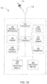
- FIG. 1B is a system diagram of an example WTRU 102.
- the WTRU 102 may include a processor 118, a transceiver 120, a transmit/receive element 122, a speaker/microphone 124, a keypad 126, a display/touchpad 128, non-removable memory 1 06, removable memory 132, a power source 134, a global positioning system (GPS) chipset 136, and other peripherals 138.
- GPS global positioning system
- the processor 118 may be.a general purpose processor, a special purpose processor, a conventional processor, a digital signal processor(DSP), a plurality of microprocessors, one or more microprocessors in association with a DSP core, a controller, a microcontroller, Application Specific Integrated Circuits (ASICs), Field Programmable Gate Array (FPGAs) circuits, any other type of integrated circuit (IC), a state machine, and the like.
- the processor 118 may perform signal coding, data processing, power control, input/output processing, and/or any other functionality that enables the WTRU 1 02 to operate in a wireless environment.
- the processor 118 may be coupled to the transceiver 120, which may be coupled to the transmit/receive element 122. While FIG. 1B depicts the processor 118 and the transceiver 120 as separate components, it will be appreciated that the processor 118 and the transceiver 120 may be integrated together in an electronic package or chip.
- the transmit/receive element 122 may be configured to transmit signals to, or receive signals from, a base station (e.g., the base station 114a) over the air interface 116.
- a base station e.g., the base station 114a
- the transmit/receive element 122 may be an antenna configured to transmit and/or receive RF signals.
- the transmit/receive element 122 may be an emitter/detector configured to transmit and/or receive IR, UV, or visible light signals, for example,
- the transmit/receive element 122 may be configured to transmit and receive both RF and light signals. It will be appreciated that the transmit/receive element 122 may be configured to transmit and/or receive any combination of wireless signal.
- the WTRU 102 may include any number of transmit/receive elements 122. More specifically, the WTRU 102 may employ MIMO technology. Thus, in one embodiment, the WTRU 102 may include two or more transmit/receive elements 122 (e.g., multiple antennas) for transmitting and receiving wireless signals over the air interface 116.
- the transceiver 120 may be configured to modulate the signals that are to be transmitted by the transmit/receive element 122 and to demodulate the signals that are received by the transmit/receive element 122.
- the WTRU 102 may have multi-mode capabilities.
- the transceiver 120 may include-multiple transceivers for enabling the WTRU 102 to communicate via multiple RATs, such as UTRA and IEEE 802.11, for example.
- the processor 118 of the WTRU 102 may be coupled to, and may receive user input data from, the speaker/microphone 124, the keypad 126, and/or the display/touchpad 128 (e.g., a liquid crystal display (LCD) display unitor organic light-emitting diode (OLED) display unit).
- the processor 118 may also output user data to the speaker/microphone 124, the keypad 126, and/or the display/touchpad 128.
- the processor 118 may access information from, and store data in, any type of suitable memory, such as the non-removable memory 106 and/or the removable memory 132.
- the non-removable memory 106 may include random-access memory (RAM), read-only memory (ROM), a hard disk, or any other type of memory storage device.
- the removable memory 132 may include a subscriber identity module (SIM) card, a memory stick, a secure digital (SD) memory card, and the like,
- SIM subscriber identity module
- SD secure digital
- the processor 118 may access information from, and store data in, memory that is not physically located on the WTRU 102, such as on a server or a home computer (not shown).
- the processor 118 may receive power from the power source 134, and may be configured to distribute and/or control the power to the other components in the WTRU 102.
- the power source 134 may be any suitable device for powering the WTRU 102.
- the power source 134 may include one or more dry cell batteries (e.g., nickel-cadmium (NiCd), nickel-zinc (NiZn), nickel metal hydride (NiMH), lithium-ion (Li-ion), etc.), solar cells, fuel cells, and the like.
- the processor 118 may also be coupled to the GPS chipset 136, which may be configured to provide location information (e,g., longitude and latitude) regarding the current location of the WTRU 101.
- location information e.g., longitude and latitude
- the WTRU 102 may receive location information over the air interface 116 from a base station (e.g., base stations 114a, 114b) and/or determine its location based on the timing of the signals being received from two or more nearby base stations. It will be appreciated that the WTRU 102 may acquire location information by way of any suitable location-determination method while remaining consistent with an embodiment.
- the processor 118 may further be coupled to other peripherals 138, which may include one or more software and/or hardware modules that provide additional features, functionality and/or wired or wireless connectivity.
- the peripherals 138 may include an accelerometer, an e-compass, a satellite transceiver, a digital camera (for photographs or video), a universal serial bus (USB) port, a Vibration device, a television transceiver, a hands free headset, a Bluetooth® module, a frequency modulated (FM) radio unit, a digital music player, a media player, a video game player module, an Internet browser, and the like.
- FIG. 1C is a system diagram of the RAN 104 and the core network 106 according to an embodiment.
- the RAN 104 may employ an E-UTRA radio technology to communicate with the WTRUs 102a, 102b, 102c over the air interface 116.
- the RAN 104 may also be in communication with the core network 106.
- the RAN 104 may include eNode-Bs 140a, 140b, 140c, though it will be appreciated that the RAN 104 may include any number of eNode-Bs while remaining consistent with an. embodiment.
- the eNode-Bs 140a 140b, 140c may each include one or more transceivers for communicating with the WTRUs 102a, 102b, 102c over the air Interface 116.
- the eNode-Bs 140a, 140b, 140c may implement MIMO technology.
- the eNode-B 140a for example, may use multiple antennas to transmit wireless signals to, and receive wireless signals from, the WTRU 102a.
- Each of the eNode-Bs 140a, 140b, 140c may be associated with a particular cell (not shown) and may be configured to handle radio resource management decisions, handover decisions, scheduling of users in the uplink and/or downlink, and the ike. As shown in FIG. 1C , the eNode-Bs 140a, 140b, 140c may communicate with one another over an X2 interface.
- the core network 106 shown in FIG. 1C may include a mobility management gateway (MME) 142, a serving gateway 144, and a packet data network (PDN) gateway 146. While each of the foregoing elements are depicted as part of the core network 106, it will be appreciated that any one of these elements may be owned and/or operated by an entity other than the core network operator.
- MME mobility management gateway
- PDN packet data network
- the MME 142 may be connected to each of the eNode-Bs 142a, 142b, 142c in the RAN 104 via an S1 interface and may serve as a control node.
- the MME 142 may be responsible for authenticating users of the WTRUs 102a, 102b, 102c, bearer activation/deactivation, selecting a particular serving gateway during an initial attach of the WTRUs 102a, 102b, 102c, and the like.
- the MME 142 may also provide a control plane function for switching between the RAN 104 and other RANs (not shown) that employ other radio technologies, such as GSM or WCDMA.
- the serving gateway 144 may be connected to each of the eNode Bs 140a, 140b, 140c in the RAN 104 via the S1 interface.
- the serving gateway 144 may generally route and forward user data packets to/from the WTRUs 102a, 102b, 102c.
- the serving gateway 144 may also perform other functions, such as anchoring user planes during inter-eNode B handovers, triggering paging when downlink data is available for the WTRUs 102a, 102b, 102c, managing and storing contexts of the WTRUs 102a, 102b, 102c, and the like.
- the serving gateway 144 may also be connected to the PDN gateway 146, which may provide the WTRUs 102a, 102b, 102c with access to packet-switched networks, such as the Internet 110, to facilitate communications between the WTRUs 102a, 102b, 102c and IP-enabled devices.
- the PDN gateway 146 may provide the WTRUs 102a, 102b, 102c with access to packet-switched networks, such as the Internet 110, to facilitate communications between the WTRUs 102a, 102b, 102c and IP-enabled devices.
- the core network 106 may facilitate communications with other networks.
- the core network 106 may provide the WTRUs 102a, 102b, 102c with access to circuit-switched networks, such as the PSTN 108, to facilitate communications between, the WTRUs 102a, 102b, 102c and traditional land-line communications devices.
- the core network 106 may include, or may communicate with, an IP gateway (e.g., an IP multimedia subsystem (IMS) server) that serves as an interface between the core network 106 and the PSTN 108.
- IMS IP multimedia subsystem
- the core network 106 may provide the WTRUs 102a, 102b, 102c with acces to the networks 112, which may include other wired or wireless networks that are owned and/or operated by other service providers.
- FDD frequency division duplex
- MBMS multimedia broadcast multicast services
- MMSFN single frequency network
- MBSFN sub-frame allocation is limited to six (6) sub-frames per frame, (for LTE FDD mode), and no MBSFN sub-frame may be configured in sub-frames #0, #4, #5 and #9 in the case of frame structure type J.
- R-PDSCH relay physical downlink shared channel
- R-PUSCH relay-physical uplink shared channel
- R-PDCCH relay-physical downlink control channel
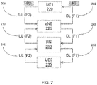
- a RN deployment is shown in Figure 2 .
- the RN 230 to eNB 225 link 210 must operate on the UL carrier, and the eNB 225 to RN 230 link 245 must operate using the DL carrier.
- the eNB 225 to RN 230 link 245 and the RN 230 to UE2 235 link 240 share the same DL carrier frequency, and similarly the RN 230 to eNB 225 link 210 and the UE2 235 to RN 230 link 205 share the same UL carrier.
- the RN 230 may appear as a regular or as a special WTRU, while simultaneously, the RN 230 may appear as a regular eNB to UE2 that is being served by the RN 230, ( i.e. , the UE2 camps on and gets service from the RN 230 in a way that is the same as from a regular eNB).
- UE1 is a WTRU that is served by the macro cNB 225
- UE2 is a WTRU that is served by the RN 230.
- the eNB 225 to RN 230 and RN 230 to UE2 235 links are time multiplexed as they share the same carrier;
- the RN 230 to eNB 225 and UE2 235 to RN 230 links are also time multiplexed in the UL frequency band F2.
- the RN 230 operates as a PDD-eNB from UE2 235 perspective, but the RN 230 itself has to support TDD operation (Tx and Rx switching) in both DL and UL carriers. Note that there is no impact on the eNB 225 as it operates in the usual fashion (DL Tx on F1, and UL Rx on F2).
- the time-multiplexing of the eNB 225 to RN 230 and RN 230 to UE2 235 links can be efficiently supported via the flexible MBSFN signaling provided by LTE R8 specifications.
- the RN configures some (up to a maximum of 6) sub-frames in the RN cell as MBSFN-reserved sub-frames. Therefore, relay WTRUs will only expect and attempt to decode the control region in these, but not expect any DL assignments or PDSCH transmission. Note that the MBSFN-reserved sub-frames in the Relay cell might not necessarily appear to the WTRU served by the donor eNB cell as MBSFN sub-frames.
- these reserved sub-frames in the Relay cell might not appear to the Relay on the backhaul link as an MBSFN sub-frames in the sense of providing MBMS services.
- the RN first transmits in the DL access link in the control region, followed by some Tx to Rx switching time (for example, 1 symbol), and receiving itself transmissions from the eNB on the DL backhaul link.
- the donor eNB can in principle transmit DL assignments (and PDSCH), DL positive acknowledgements (ACKs)/negative acknowledgements (NACKs) on physical hybrid automatic repeat request ((HARQ) indicator channel (PHICH) and UL grants (for PUSCH) to its served macro WTRUs in any DL sub-frame however in order to avoid self-interference between the Relay transmitter and receiver, the donor eNB should mater DL transmission in sub-frames broadcasted by the RN in its cell as MBSFN sub-frames. Similarly, the RN may transmit DL ACKs/NACKs and UL grants to its served relay WTRUs in any DL sub-frame. However, in order to avoid self-interference between the Relay transmitter and receiver, the RN may transmit PDSCH to its relay WTRUs only in sub-frames not configured as MBSFN sub-frames.
- HARQ physical hybrid automatic repeat request
- PUSCH physical hybrid automatic repeat request
- the access link DL sub-frame boundary is aligned with the backhaul link DL sub-frame boundary (except for possible adjustment to allow for RN Tx/Rx switching).
- the set of DL backhaul sub-frames, during which DL backhaul transmission may occur is time-domain resources (set of sub-frames) that may be used for the DL backhaul link, and are semi-statically assigned. It has not been determined whether the time-domain resources for the UL backhaul link are to be also semistatically assigned.
- the set of UL backhaul subframes, during which UL backhaul transmission may occur can be semi-statically assigned, or implicitly derived from the DL backhaul subframes using the HARQ timing relationship.
- a new physical control channel which may be called the relay physical downlink control channel (R-PDCCH) may be used to dynamically or "semi-persistently" assign resources, within the semi-statically assigned sub-frames, for the DL backhaul data, the relay physical downlink shared channel (R-PDSCH).
- the R-PDCCH is also used to dynamically or "semi-persistently” assign resources for the UL backhaul data, the relay physical uplink shared channel (R-PUSCH).
- the R-PDCCH may be transmitted on a subset of the physical resource blocks (PRBs) of the subframes assigned for the DL backhaul link.
- a predefined number of resource blocks (RBs) may be reserved for a backhaul control channel.
- the reserved RBs may be fixed by the specifications, semi-statically signaled to relay node, or signaled via any other channel, e.g ., relay-physical control format indicator channel (R-PCFICH).
- R-PCFICH relay-physical control format indicator channel
- the R-PCFICH itself may be located in a standard specified RB, ( e.g ., center of bandwidth).
- the R-PDCCH may be transmitted on a subset of the orthogonal frequency division multiplexing (OFDM) symbols of the subframes assigned for the DL backhaul link. This subset of OFDM symbols may include the full set of OFDM symbols available for the backhaul link.
- the R-PDCCH may be transmitted starting from an OFDM symbol within the subframe that is late enough so that the RN can receive it.
- the R-PDCCH may be used to assign DL resources in the same subframe and/or in one or more later subframes.
- the R-PDCCH may be used to assign UL resources in one or more later subframes.
- the R-PDSCH and the R-PDCCH may be transmitted within the same PRBs or within separated PRBs.
- the backhaul control channel RBs may carry R-PDCCH, relay- physical hybrid automatic repeat request (HARQ) indicator channel (R-PHICH) and if needed, R-PCFICH.
- HARQ relay- physical hybrid automatic repeat request
- Frequency division multiplexing FDM
- time division multiplexing TDM
- TDM+ FDM TDM + TDM
- Backhaul control channels design may require details of control channel mapping in frequency and time domains at the eNodeB, and decoding at the relay (or any other receiver of R-PDCCH such as a WTRU), of the control channels without the use of R-PCFICH.
- the methods, systems and apparatuses herein support ACK/NACK, reduction of R-PDSCH decoding delay, reduction of blind search processing time and related power consumption, minimization of the amount of overhead signaling for control channels, and minimization of the bandwidth requirement for control channels.
- Relay operation is described herein for the case of in-band, (i . e ., RN-eNB link share the same carrier with RN to WTRU access link), in FDD networks.
- methods and procedures described are equally applicable to TDD networks.
- relay design on the Un interface between a RN and an eNB is described.
- several methods and procedures are described of how one or more control signal(s), i.e ., eNB to RN DL ACK/NACK and R-PDCCH to carry Un DL assignments or Un UL grants, are encoded and transmitted from the eNB to the RN. While the ideas presented herein are primarily described using relay type I terminology, they are applicable to other types of relays as well, notably non-transparent or non-self-backhauling type of relays amongst others.
- a method is described for control channel mapping with multiplexing and interleaving of R-PDCCHs from multiple relays. If interleaving is applied, it may be performed on an OFDM symbol basis. R-PCFICH may not be used.
- Methods are described of mapping of the R-PDCCH in the time-frequency grid, where the R-PDCCH is first mapped along the frequency domain across the OFDM symbols of the control channel (which also may be referred to as OFDM control symbols) followed by the time domain.
- OFDM control symbols which also may be referred to as OFDM control symbols
- One advantage of the frequency first mapping is to eliminate the use of R-PCFICH or similar channels.
- a tree based assignment of RBs may be used to minimize the resource allocation overhead.
- a method is described to configuring the relay specific configuration parameters.
- Dedicated R-PDCCH (and downlink control information (DCI) format) in support of ACK/NACK are described, whereby R-PHICH/PHICH channel performance requirements are typically more stringent than a typical R-PDCCH/PDCCH.
- Signaling of ACK/NACK over R-PDCCH may be employed when R-PHICH is not used.
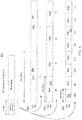
- FIG. 3 shows an example of backhaul control channel mapping.
- Assignments in the frequency domain may be in units of RBs or resource block groups (RBGs) or any other unit thereof.
- RBGs resource block groups
- the units may be considered to be RBs with the understanding that the design scales according to the units.
- the relay control channels may be mapped uniformly across the entire spectrum.
- N I,RB DL modulo N I,RB DL .
- the RBs with indices 15 and. 19 correspond to OFDM symbol "l", while the RB with indices 3, 7 and 11 (which are the RB where the wrap-around occurs), may be mapped according to this invention to either OFDM symbol "l", or OFDM symbol "1+1".
- the donor eNB might not utilize N l,MAX_REL_RB RBs. It is not necessary to signal the actual number of RBs used.
- the relay node may perform blind decoding over a varying number of RBsuntil it finds the required number of grants or reaches N l,MAX_REL_RB .
- the donor eNB may be restricted to use only a pre-determined number of RBs, ( e.g ., from the set ⁇ 1,2,4,8, N l,MAX_REL_RB ⁇ ).
- backhaul control channel RB allocations may be made conformant to resource allocation types 0, 1 or 2.
- control channel can be split between the two time slots in a manner similar to PDSCH.
- mapping modes can be defined and signaled via higher layers. Higher layer signaling could be achieved through system information broadcast (with additional Information Element such as control channel RB configuration mode or RB allocation bit map in. SIB2 for example), RRC (Radio Resource Control) signaling or NAS signaling. As an example, with 3 bits, 8 modes can be defined as shown to Table 1 below.
- Preconfigured allocation may imply that the parameters that determine the exact RBs in each allocation type are standardized. For allocation 0 and 1, the value of RBG zize, P, and the allocation bit map may be known. Fof type 2 allocation, the starting resource block, RB start , L CRBs , and the step size, N RB step are standard specified. Alternatively all the parameters may be signaled along with the operational mode.
- the RN might be required to support all backhaul control channel mapping options or alternatively a subset of the available backhaul control channel mapping options.. Alternatively, a default backhaul control channel mapping option is specified.
- the network can signal the backhaul control channel mapping options supported by the network in a system information broadcast message (SIB2 for example) or in RRC signaling or a combination of both. For instance, when the RN is not connected to the network, the RN can acquire the backhaul control channel mapping information through system information broadcast messages. On the other hand, when the RN is in connected mode already, update to backhaul control channel mapping method can be acquired via RRC signaling.
- SIB2 system information broadcast message
- RRC signaling or a combination of both.
- the RPDSCH may be mapped using one of the resource allocation types used for PDSCH.
- the R-PDCCH which may be mapped to RBs, contains the resource allocation for R-PDSCH.
- the RBs assigned to R-PDSCH may also carry the backhauL control channel, then the RB may be time multiplexed with backhaul control channels.
- S-PDSCH may be punctured to accommodate R-PDCCH.
- R-PCFICH (when used) and R-PHICH may be mapped uniformly across all available backhaul control channel RBs.
- R-PCFICH (when used) and R-PHICH may be mapped in only part ( e.g ., one third) of the RB.
- FIG. 4 shows an example of mapping the R-PHICH and R-PDCCH over an OFDM symbol when R-PCFICH is not used.
- FIG. 5 shows an example of mapping the R-PHICH and R-PDCCH over an OFDM symbol when R-PCFICH is used.
- the R-PCFICH (when used) may be mapped beginning from a RB whose index is obtained from the donor eNB cell identity (ID).
- the R-PHICH may be mapped according to an R8 procedure.
- the other part of the RB may be used by R-PHICH 525 and/or R-PDCCH 520.
- the remaining RBs may be occupied by R-PDCCH.
- the encoded PDCCH for R8 WTRUs are divided into control channel elements (CCEs) and interleaved before being mapped to the time-frequency grid. Mapping is in time-first order. Hence, the number of OFDM control symbols must be known before the decoding process can begin.
- CCEs control channel elements
- Time first mapping does not provide any significant advantage in a relay environment due to limited or no mobility.
- the R-PDCCH may be mapped in frequency first order, so that decoding can begin as soon as every OFDM symbol is processed and made available to control channel processing unit. This avoids need to signal the number of OFDM control symbols. Example methods display below.
- the donor eNB multiplexes the R-PDCCH of all of the relay nodes in a manner similar to R8.
- the donor eNB may map the multiplexed bit streams to CCEs by simple partitioning of the multiplexed R-PDCCH into units of GGEs or similar.
- the donor eNB may partition the CCE space into n vectors, where n is the number of backhaul OFDM control symbols.
- the donor eNB transmits data. The method in Figure 6A allows a CCE to be mapped across two consecutive OFDM symbols.
- the order in which the CCEs are mapped to (RBs) is the same as the order of R-PDCCHs in the multiplexed vector.
- FIG. 6B shows an example of the embodiment where the mapping is performed over two OFDM symbols and a CCE may be mapped across two OFDM symbols.
- the first OFDM symbol may comprise one or more whole control channel elements (e.g ., CCE #1, #2, and #3) and one partial control channel element (e.g ., CCE #4 which spans over OFDM symbol #1 and #2).
- R8 techniques are reused for modulation, interleaving and pre-coding.
- the i th vector is mapped over the i th OFDM symbol reserved for the backhaul OFDM control symbol along increasing (or decreasing) order of RBs.
- the CCEs may be mapped to frequency and time domains. Note that the mapping may be performed in the frequency first order unlike R8, where the mapping is: performed in time first order.
- FIG. 6C displays what may occur at the receiver, for each OFDM control symbol.
- a processor may receive from an eNodeB, for example, consecutive first and second OFDM symbols that represent a plurality of relay physical downlink control channels (R-PDCCH) that comprises a first R-PDCCH and a second R-PDCCH. Then the processor may decode the first R-PDCCH from the first OFDM symbol, which is received before the second OFDM symbol.
- R-PDCCH relay physical downlink control channels
- the RN demarcates the i th vector at CCE boundaries where bits beyond the integer number of CCEs are considered as a part of the following OFDM control symbol
- fhe RN may perform blind decoding over the CCEs on a per OFDM control symbol basis. This is possible since interleaving may be performed over the span of a single OFDM symbol.
- the RN continues to decode following vector of demodulated bits. There is a "CCE wrap around" that the RN has to account for. If there are more OFDM control symbols (i.e ., Yes at block 694) the bits not used for blind decoding in the previous OFDM control symbol are appended to the vector of bits from the current OFDM symbol. The RN may start again at block 686 and process the reconstructed vector of demodulated bits.
- the RN checks at block 691 if all monitored R-PDCCH (i.e . all monitored RNTIs) have been detected.
- the RN may continue decoding until the required number of R-PDCCH are found ( i.e ., Yes at block 691) or the maximum number of OFDM control symbols are reached ( i.e ., No at block 694).
- the maximum number of OFDM control symbols can be standardized, or tied to other system parameters like bandwidth, or signaled by higher layers.
- the donor eNB may multiplex the R-PDCCH of all the relay nodes in a manner similar to R8.
- the donor eNB may compute the number of CCEs that can be mapped over each available OFDM symbol, such that every CCE is mapped within a single OFDM symbol (that is, no CCE spans two OFDM symbols).
- the donor eNB may determine what OFDM control symbols to place the given R-PDCCH in.
- the donor eNB, for each symbol may determine the beginning CCE index of every candidate R-PDCCH using a hashing function.
- the hashing function may be an eNB specific scheduling algorithm that optimizes scheduling or any other parameter. For example, if the R-PDCCH carries a downlink assignment, to reduce the latency in decoding the data, the hashing function in the donor eNB may map it to a CCE allocated on the first OFDM control symbol. Similarly, if the R-PDCCH carries an UL grant, the donor eNB may map it to a CCE allocated to the second or third OFDM control symbol (this is because the UL transmission needs to be performed 4 ms later, so the latency in decoding the control channel is not a main concern).
- the hashing function may be a randomizing function with input parameters selected from the following set: sub-frame number, aggregation level, time slot index, or a relay specific identifier like relay radio network temporary identity (RNTI).
- RNTI relay radio network temporary identity
- CCEs with aggregation level 2 may be mapped to the first OFDM control symbol in even sub-frames, and to the second OFDM control symbol in odd sub-frames.
- the hashing function may also include multiplexing of candidate R-PDCCHs followed by simple partitioning into unite of CCE or similar. Additionally, a modulo rotational shift may be applied where the shift is determined based on some or all of the parameters specified herein.
- the modulated and pre-coded symbols are mapped, in frequency first order over the RBs allocated for backhaul.
- FIG. 7B shows an example of the embodiment where the mapping is performed over two OFDM symbols and the CCBs may not be mapped across two OF DMsymbols.
- the first OFDM symbol may comprise one or more whole control channel elements (e.g ., CCE #1. and #2) and padding (e.g., N which may be padding) if the insertion of a CCE would go beyond the number of bits available in a OFDM symbol.
- FIG. 7C displays what may occur at the receiver, for each OFDM control symbol.
- the RN demarcates the i th vector at CCE boundaries and discards NULL bits beyond the integer number of CCEs.
- the RN may perform blind decoding over the CCEs on a per OFDM symbol basis. This is possible since interleaving and CCE randomization may be performed over the span of a single OFDM control symbol.
- the relay may determine the candidate CCEs over which to perform the decoding. If no R-PDCCH addressed to the relay node is found ( i . e ., No at block 790) and there are more OFDM control symbols ( i.e. , Yes at block 794), the RN continues to decode over the following vector of demodulated bits. If a R-PDCCH addressed to the relay node is detected ( i.e ., Yes at block 790), then at block 791 the RN checks if all monitored R-PDCCH ( i.e ., all monitored RNTIs) were detected.
- all monitored R-PDCCH i.e ., all monitored RNTIs
- the RN may continue decoding until the required number of R-PDCCH are found (i.e ., Yes at block 791) or the maximum number of OFDM control symbols are reached (i.e ., No at block 794).
- the maximum number of OFDM control symbols may be standardized, or tied to other system parameters like bandwidth, or signaled by higher layers.
- Dedicated RBs may be distributed amongst the RNs in a semi-static function. If there are K RBs allocated for relays in an area, then with b bits, K /2 b RBs may be assigned to 2 b relays or K /2 b-1 RBs to 2 b-1 relays and so on. Both K and b may be known to the relay nodes via higher layer signaling or relay system information. Depending on b , the DCI format lengths may change, and the relay nodes may perform blind decoding accordingly as shown in FIG. 8 , which shows reduced bit map for resource allocation.
- resources may be signaled to two relay nodes.
- RN 1 at 806 may be assigned the first half of total of K RBs and RN 2 at. 807 may be assigned the next half.
- resources may be signaled to 4 relay nodes.
- RN1, 812 may be assigned the first K /4 RBs.
- equal resources may be assigned to eight relays.
- RN1 may be assigned the first K /8.
- Relay "X" may be assigned the "Y" sub-set by sending the appropriate 3-bit header. More specifically, if only relays 3,4,5,6,7,8 are assigned DL resources, RN 3 may be assigned sub-set #0 by signaling '000' in the header, RN 4 may be assigned sub-set #1 by signaling '001' in the header and so on. The remaining sub-sets (#6 and #7) may be reused by the donor eNB to schedule DL data for the macro WTRUs.
- This method may be applied when the RBs dedicated to the R-PDSCH (DL backhaul data) for the relays may be split equally between all the RN connected to the eNB. Although this method has less scheduling granularity in the frequency domain, it has the advantage of low overhead, since it does not require the transmission of the resource allocation bitmap that is employed in resource allocation Type 0 or Type 1. Alternately, if the start of each sub-set is also signaled, then the restriction for equal resource allocation for the RNs may be lifted.
- a delay may be included between R-PDCCH and R-PDSCH (DL resource) and between R-PDCCH and R-PUSCH (UL grant) where the delay may be equal to or greater than 0 in a unit of subframes.
- This may allow for R-PDCCH to provide DL assignment or UL grants in later sub-frames (i.e ., R-PDCCH. to R-PDSCH is ⁇ D sub-frames ( ⁇ D >1), and R-PDCCH to -PUSCH is ⁇ D >4), If the R-PDCCH grants uplink resources on the backhaul link in one or more later sub-frames, the RN knows in advance the sub-frames that will be used for UL data backhaul.
- the RN knows in advance what subframes will be needed: for UL transmission of the ACK/NACK feedback on the backhaul.
- the RN may then schedule the R-WTRUs such that collisions between the UL access link and the UL backhaul are avoided (or minimized). Note that the R-WTRUs are the UEs in the RN cell that may be served by the RN.
- the eNB may configure the delay ( ⁇ D or ⁇ U ) for each RN (or a group of RNs) semi-statically or dynamically.
- a value of the delay is signaled to the RN(s) through higher layers.
- the value may be included in R-PDCCH by introducing a new DCI format where the value of the delay may be represented by a few bits ( e.g ., 2 or 3 bits).
- a delay indicator may be introduced/used in the backhaul control region to indicate a value of ⁇ D or ⁇ U .
- a binary delay indicator for DL resources e.g ., R-PDSCH
- "0" represents zero delay (e.g., meaning R-PDSCH in the same subframe as R-PDCCH)
- white “1” means the presence of DL resources ( e.g ., RPDSCH) in one (or more) later subfrarme(s) associated with the current subframe.
- the delay ⁇ D or ⁇ U may be applied, whereby 1) ⁇ D or ⁇ U corresponds to a delay applied immediately after the sub-frame in which the grant is received or 2) the delay, to reduce the number of bits and allow more flexibility, can be relative to a known baseline sub-frame in the future. For example, in respect with baseline sub-frame, in case of uplink, the delay may be with respect to sub-frame n +4, where n is the sub-frame in which the grant is received. Furthermore, ⁇ D or ⁇ U may also take negative values which would imply an advancement from the baseline sub-frame.
- the parameters to configure the relay node may be signaled semi-statically or may be preconfigured.
- the relay When the relay starts up, it may behave as a regular UE. Any relay specific configuration parameters may be exchanged via radio resource control (RRC) messages.
- RRC radio resource control
- the relay may use this configuration information to transition from its UE identity to the relay identity.
- the A/N for UL transmission is signaled on the DL PHICH channel.
- the A/N for relay UL backhaul can be sent via a R-PDCCH.
- the DCI format carried by the R-PDCCH may bean extension of the relay specific DCI formats to include A/N information.
- a special DCI format may be created that carries the A/Ns for one or several Relay nodes. This DCI format may be transmitted using an R-PDCCH with a special RNTI that signifies that the DCI format is intended for A/N.
- such an R-PDCCH may be encoded with a low coding rate by using a higher aggregation level than the R-PDCCHs used for UL and DL grants.
- the aggregation level of such a R-PDCCH may be specified in the standards;
- Examples of computer-readable storage media include, but are not limited to, a read only memory (ROM), a random access memory (RAM), a register, cache memory, semiconductor memory devices, magnetic media such as internal hard disks and removable disks, magneto-optical media, and optical media such as CD-ROM disks, and digital versatile disks (DVDs),
- ROM read only memory
- RAM random access memory
- register cache memory
- semiconductor memory devices magnetic media such as internal hard disks and removable disks, magneto-optical media, and optical media such as CD-ROM disks, and digital versatile disks (DVDs)
- a processor in association with software may be used to implement a radio frequency transceiver for use in a WTRU, UE, terminal, base station, RNC, or any host computer.
Claims (15)
- Verfahren, welches in einem Relaisknoten, RN, implementiert wird, zum Empfangen eines physikalischen Relais-Downlink-Steuerkanals, R-PDCCH, wobei das Verfahren umfasst:Empfangen einer R-PDCCH-Transmission von einem evolved NodeB, eNB, in einem Subrahmen, der von dem RN als Multimedia-Broadcast-Multicast-Services-, MBMS-, Einzelfrequenz-Netz-, MBSFN-, Subrahmen ausgelegt wird; undDemodulieren der empfangenen R-PDCCH-Transmission in demodulierte R-PDCCH-Bits;Decodieren der demodulierten R-PDCCH-Bits auf einer Basis per OFDM-Symbol, wobei die R-PDCCH-Bits erstens entlang einer Frequenzdomäne eines orthogonalen Frequenzteilungs-Multiplexing-, OFDM-, Symbols und zweitens in einer Zeitdomäne quer über ein oder mehrere OFDM-Symbole gemappt werden.
- Verfahren nach Anspruch 1, wobei die decodierten R-PDCCH-Bits auf eine vorherbestimmte Anzahl von Ressourcenblöcken, RBs, gemappt werden, und die vorherbestimmte Anzahl von RBs in einer Funkressourcensteuerungs-, RRC-, Nachricht angezeigt werden.
- Verfahren nach Anspruch 1, wobei, dass die R-PDCCH-Transmission eine Downlink-Ressourcenzuordnung anzeigt, auch in dem Subrahmen enthalten ist, der die R-PDCCH-Transmission umfasst.
- Verfahren nach Anspruch 1, wobei R-PDCCH-Transmission bei einem Start-OFDM-Symbol beginnt und in einem Subsatz von OFDM-Symbolen empfangen wird, die in dem Subrahmen enthalten sind, der die R-PDCCH-Transmission umfasst.
- Verfahren nach Anspruch 4, wobei das Start-OFDM-Symbol nicht das erste OFDM-Symbol des Subrahmens ist, der die R-PDCCH-Transmission umfasst.
- Verfahren nach Anspruch 1, wobei die Ressourcenblock-, RB-, Zuordnungen des R-PDCCH mindestens einer von einem Ressourcenzuordnungstyp 0, einem Ressourcenzuordnungstyp 1 oder einem Ressourcenzuordnungstyp 2 sind.
- Verfahren nach Anspruch 6, wobei die RB-Zuordnung des R-PDCCH eine Ressourcenzuordnung vom Typ 2 ist und eine Zuordnung verteilter virtueller Ressourcenblöcke, VRBs, umfasst.
- Relaisknoten, RN, zum Empfangen eines physikalischen Relais-Downlink-Steuerkanals, R-PDCCH, wobei der RN umfasst:einen Empfänger, der ausgelegt ist, eine R-PDCCH-Transmission von einem evolved NodeB, eNB, in einem Subrahmen zu empfangen, der von dem RN als Multimedia-Broadcast-Multicast-Services-, MBMS-, Einzelfrequenz-Netz-, MBSFN-, Subrahmen ausgelegt wird; undeinen Prozessor, der ausgelegt ist:die empfangene R-PDCCH-Transmission in demodulierte R-PDCCH-Bits zu demodulieren; unddie demodulierten R-PDCCH-Bits auf einer Basis per OFDM-Symbol zu decodieren, wobei die R-PDCCH-Bits erstens entlang einer Frequenzdomäne eines orthogonalen Frequenzteilungs-Multiplexing-, OFDM-, Symbols und zweitens in einer Zeitdomäne quer über ein oder mehrere OFDM-Symbole gemappt werden.
- RN nach Anspruch 8, wobei die decodierten R-PDCCH-Bits auf eine vorherbestimmte Anzahl von Ressourcenblöcken, RBs, gemappt werden, und der Empfänger ferner ausgelegt ist, eine Funkressourcensteuerungs-, RRC-, Nachricht zu empfangen, welche die vorherbestimmte Anzahl von RBs anzeigt.
- RN nach Anspruch 8, wobei die R-PDCCH-Transmission bei einem Start-OFDM-Symbol beginnt und in einem Subsatz von OFDM-Symbolen zu empfangen ist, die in dem Subrahmen enthalten sind, der die R-PDCCH-Transmission umfasst.
- RN nach Anspruch 10, wobei das Start-OFDM-Symbol nicht das erste OFDM-Symbol des Subrahmens ist, der die R-PDCCH-Transmission umfasst.
- RN nach Anspruch 8, wobei die Ressourcenblock-, RB-, Zuordnungen des R-PDCCH mindestens einer von einem Ressourcenzuordnungstyp 0, einem Ressourcenzuordnungstyp 1 oder einem Ressourcenzuordnungstyp 2 sind.
- RN nach Anspruch 12, wobei die RB-Zuordnung für den R-PDCCH eine Ressourcenzuordnung vom Typ 2 ist und eine Zuordnung verteilter virtueller Ressourcenblöcke, VRBs, umfasst.
- RN nach Anspruch 8, wobei mindestens eine R-PDCCH-Transmission mehrere OFDM-Symbole überspannt.
- Evolved NodeB, eNB, zum Übertragen eines physikalischen Relais-Downlink-Steuerkanals, R-PDCCH, wobei der eNB umfasst:
einen Prozessor, der ausgelegt ist:eine Vielzahl von R-PDCCH-Bits auf einer Basis per orthogonalem Frequenzteilungs-, OFDM-, Symbol zu codieren, wobei die Vielzahl von R-PDCCH-Bits erstens entlang einer Frequenzdomäne eines OFDM-Symbols und zweitens in einer Zeitdomäne quer über ein oder mehrere OFDM-Symbole gemappt werden, und die Vielzahl von R-PDCCH-Bits zu modulieren, um modulierte R-PDCCH-Bits zu bilden; undeinen Sender, der ausgelegt ist, eine R-PDCCH-Transmission, welche die modulierten R-PDCCH-Bits umfasst, zu einem Relaisknoten, RN, in einem Subrahmen zu übertragen, der von dem RN als Multimedia-Broadcast-Multicast-Services-, MBMS-, Einzelfrequenz-Netz-, MBSFN-, Subrahmen ausgelegt wird.
Applications Claiming Priority (4)
| Application Number | Priority Date | Filing Date | Title |
|---|---|---|---|
| US23412409P | 2009-08-14 | 2009-08-14 | |
| US25615909P | 2009-10-29 | 2009-10-29 | |
| PCT/US2010/045325 WO2011019916A1 (en) | 2009-08-14 | 2010-08-12 | Dl backhaul control channel design for relays |
| EP10762780.4A EP2465320B1 (de) | 2009-08-14 | 2010-08-12 | Design für dl backhaul-kontrolkanal für relais |
Related Parent Applications (1)
| Application Number | Title | Priority Date | Filing Date |
|---|---|---|---|
| EP10762780.4A Division EP2465320B1 (de) | 2009-08-14 | 2010-08-12 | Design für dl backhaul-kontrolkanal für relais |
Publications (2)
| Publication Number | Publication Date |
|---|---|
| EP2996276A1 EP2996276A1 (de) | 2016-03-16 |
| EP2996276B1 true EP2996276B1 (de) | 2018-12-05 |
Family
ID=43125626
Family Applications (2)
| Application Number | Title | Priority Date | Filing Date |
|---|---|---|---|
| EP10762780.4A Active EP2465320B1 (de) | 2009-08-14 | 2010-08-12 | Design für dl backhaul-kontrolkanal für relais |
| EP15189998.6A Active EP2996276B1 (de) | 2009-08-14 | 2010-08-12 | Gestaltung eines dl-backhaul-steuerkanals für relais |
Family Applications Before (1)
| Application Number | Title | Priority Date | Filing Date |
|---|---|---|---|
| EP10762780.4A Active EP2465320B1 (de) | 2009-08-14 | 2010-08-12 | Design für dl backhaul-kontrolkanal für relais |
Country Status (10)
| Country | Link |
|---|---|
| US (5) | US8976806B2 (de) |
| EP (2) | EP2465320B1 (de) |
| JP (2) | JP5560332B2 (de) |
| KR (2) | KR101446400B1 (de) |
| CN (2) | CN102577568B (de) |
| DK (1) | DK2465320T3 (de) |
| HK (1) | HK1219822A1 (de) |
| IL (1) | IL218050A0 (de) |
| TW (1) | TWI494015B (de) |
| WO (1) | WO2011019916A1 (de) |
Cited By (1)
| Publication number | Priority date | Publication date | Assignee | Title |
|---|---|---|---|---|
| CN106506424A (zh) * | 2015-09-07 | 2017-03-15 | 普天信息技术有限公司 | 中继回传链路的控制信道传输方法 |
Families Citing this family (86)
| Publication number | Priority date | Publication date | Assignee | Title |
|---|---|---|---|---|
| EP2076066B1 (de) * | 2007-12-05 | 2013-07-17 | Nokia Siemens Networks Oy | Verfahren zum Senden von Systeminformation, und Programmelement, Computer-lesbares Medium, Basisstation und Benutzer-Endgerät |
| US8755807B2 (en) * | 2009-01-12 | 2014-06-17 | Qualcomm Incorporated | Semi-static resource allocation to support coordinated multipoint (CoMP) transmission in a wireless communication network |
| US9673952B2 (en) | 2009-04-10 | 2017-06-06 | Qualcomm Inc. | Method and apparatus for supporting user equipments on different system bandwidths |
| EP2446552B1 (de) * | 2009-06-24 | 2016-08-10 | Nokia Solutions and Networks Oy | RELAISKNOTEN UND VERFAHREN ZUM ÄNDERN DES ZEITSCHLITZTYPS GEMÄß DEN EMPFANGENEN INFORMATIONEN |
| US20120128039A1 (en) * | 2009-07-16 | 2012-05-24 | Lg Electronics Inc. | Method and apparatus for transmitting and receiving control channel for relay backhaul link in wireless communication system |
| US8837347B2 (en) | 2009-07-17 | 2014-09-16 | Lg Electronics Inc. | Method and apparatus for transmitting reference signal in wireless communication system including relay station |
| CN102036262A (zh) * | 2009-09-25 | 2011-04-27 | 中兴通讯股份有限公司 | 一种下行控制信息的检测方法和装置 |
| CN102036398B (zh) * | 2009-09-29 | 2015-06-03 | 中兴通讯股份有限公司 | 一种中继节点及其传输数据的方法 |
| KR101714439B1 (ko) * | 2009-10-28 | 2017-03-09 | 엘지전자 주식회사 | 기지국으로부터 제어정보를 수신하는 중계기 장치 및 그 방법 |
| US9014080B2 (en) * | 2009-10-30 | 2015-04-21 | Qualcomm Incorporated | Apparatus and method for providing relay backhaul communications in a wireless communication system |
| US9276710B2 (en) * | 2009-12-21 | 2016-03-01 | Qualcomm Incorporated | Method and apparatus for resource allocation with carrier extension |
| US8594010B2 (en) * | 2010-01-11 | 2013-11-26 | Qualcomm Incorporated | Apparatus and method for physical control format indicator channel (PCFICH) information sharing over relay backhaul link |
| GB201000449D0 (en) | 2010-01-12 | 2010-02-24 | Nec Corp | Relay communication system |
| CN105450379B (zh) * | 2010-01-26 | 2018-11-27 | Lg电子株式会社 | 在无线通信系统中分配资源的方法和设备 |
| US20110194511A1 (en) * | 2010-02-10 | 2011-08-11 | Qualcomm Incorporated | Multi-user control channel assignment |
| EP2545661B1 (de) * | 2010-03-11 | 2015-05-06 | Nokia Solutions and Networks Oy | Optimierte signalisierung in relaisverstärkten zugangsnetzen |
| US20130035033A1 (en) * | 2010-03-15 | 2013-02-07 | Henning Sanneck | Relay Nodes |
| US9654265B2 (en) * | 2010-04-08 | 2017-05-16 | Qualcomm Incorporated | Systems, apparatus and methods to facilitate transmission of acknowledgement signals in wireless communication systems |
| US9014081B2 (en) * | 2010-04-09 | 2015-04-21 | Futurewei Technologies, Inc. | System and method for transmitting control information |
| US9197363B2 (en) * | 2010-04-13 | 2015-11-24 | Lg Electronics Inc. | Method and device for receiving downlink signal |
| US20130016653A1 (en) * | 2010-04-14 | 2013-01-17 | Hak Seong Kim | Method for setting a search space for a relay node in a wireless communication system and apparatus for same |
| WO2011132946A2 (ko) * | 2010-04-22 | 2011-10-27 | 엘지전자 주식회사 | 무선 통신 시스템에서 기지국과 릴레이 노드 간의 신호 송수신 방법 및 이를 위한 장치 |
| CN102893688B (zh) * | 2010-05-14 | 2016-03-09 | Lg电子株式会社 | 在无线通信系统中分配资源的方法及其装置 |
| CN102281636B (zh) * | 2010-06-12 | 2016-04-13 | 中兴通讯股份有限公司 | 中继链路的物理下行控制信道的资源分配方法及系统 |
| US8787304B2 (en) * | 2010-06-22 | 2014-07-22 | Acer Incorporated | Method for reference signal pattern allocation and related communication device |
| US8548514B2 (en) * | 2010-08-11 | 2013-10-01 | Lg-Ericsson Co., Ltd. | Method for resource element group downsizing of R-PDCCH and mobile telecommunication system for the same |
| US9185711B2 (en) | 2010-09-14 | 2015-11-10 | Qualcomm Incorporated | Method and apparatus for mitigating relay interference |
| CN102480347B (zh) * | 2010-11-23 | 2015-06-03 | 中兴通讯股份有限公司 | 中继链路子帧配置切换时确认信息的反馈方法及装置 |
| US9491766B2 (en) * | 2010-12-08 | 2016-11-08 | Nokia Technologies Oy | Device-to-device communication scenario |
| US8902833B2 (en) * | 2010-12-23 | 2014-12-02 | Qualcomm Incorporated | System and method for performing a radio link control (RLC) reset in a downlink multipoint system |
| US9198094B2 (en) * | 2011-02-24 | 2015-11-24 | Lg Electronics Inc. | Method for setting search space for handover of relay node in wireless communication system, and device therefor |
| GB2491335A (en) * | 2011-03-24 | 2012-12-05 | Wireless Tech Solutions Llc | A relay node receives broadcast data on a first channel and retransmits the broadcast data on a second channel |
| CN102143597B (zh) * | 2011-03-31 | 2014-02-05 | 电信科学技术研究院 | 下行数据的传输方法和设备 |
| WO2012150827A2 (ko) * | 2011-05-04 | 2012-11-08 | 엘지전자 주식회사 | 무선 통신 시스템에서 단말이 ack/nack 응답을 송신하는 방법 및 이를 위한 장치 |
| CN102843701B (zh) * | 2011-06-21 | 2018-02-13 | 爱立信(中国)通信有限公司 | 时分双工通信网络中的中继部署方法和设备 |
| US8526961B2 (en) | 2011-06-29 | 2013-09-03 | Alcatel Lucent | Method and apparatus for mapping operating parameter in coverage area of wireless network |
| CN102264136B (zh) * | 2011-08-08 | 2017-02-15 | 中兴通讯股份有限公司 | 一种控制信道资源配置方法及配置装置 |
| US8238318B1 (en) | 2011-08-17 | 2012-08-07 | CBF Networks, Inc. | Intelligent backhaul radio |
| US8385305B1 (en) | 2012-04-16 | 2013-02-26 | CBF Networks, Inc | Hybrid band intelligent backhaul radio |
| US10548132B2 (en) | 2011-08-17 | 2020-01-28 | Skyline Partners Technology Llc | Radio with antenna array and multiple RF bands |
| US8502733B1 (en) | 2012-02-10 | 2013-08-06 | CBF Networks, Inc. | Transmit co-channel spectrum sharing |
| US8422540B1 (en) | 2012-06-21 | 2013-04-16 | CBF Networks, Inc. | Intelligent backhaul radio with zero division duplexing |
| US8761100B2 (en) * | 2011-10-11 | 2014-06-24 | CBF Networks, Inc. | Intelligent backhaul system |
| US8989762B1 (en) | 2013-12-05 | 2015-03-24 | CBF Networks, Inc. | Advanced backhaul services |
| US9049611B2 (en) | 2011-08-17 | 2015-06-02 | CBF Networks, Inc. | Backhaul radio with extreme interference protection |
| US10051643B2 (en) | 2011-08-17 | 2018-08-14 | Skyline Partners Technology Llc | Radio with interference measurement during a blanking interval |
| US10716111B2 (en) | 2011-08-17 | 2020-07-14 | Skyline Partners Technology Llc | Backhaul radio with adaptive beamforming and sample alignment |
| US10764891B2 (en) | 2011-08-17 | 2020-09-01 | Skyline Partners Technology Llc | Backhaul radio with advanced error recovery |
| US8928542B2 (en) | 2011-08-17 | 2015-01-06 | CBF Networks, Inc. | Backhaul radio with an aperture-fed antenna assembly |
| US9713019B2 (en) | 2011-08-17 | 2017-07-18 | CBF Networks, Inc. | Self organizing backhaul radio |
| US10708918B2 (en) | 2011-08-17 | 2020-07-07 | Skyline Partners Technology Llc | Electronic alignment using signature emissions for backhaul radios |
| US8467363B2 (en) | 2011-08-17 | 2013-06-18 | CBF Networks, Inc. | Intelligent backhaul radio and antenna system |
| US8982772B2 (en) | 2011-08-17 | 2015-03-17 | CBF Networks, Inc. | Radio transceiver with improved radar detection |
| US9474080B2 (en) | 2011-08-17 | 2016-10-18 | CBF Networks, Inc. | Full duplex backhaul radio with interference measurement during a blanking interval |
| US9788327B2 (en) * | 2011-11-14 | 2017-10-10 | Qualcomm Incorporated | Methods and apparatus for reducing interference in a heterogeneous network |
| US8606286B2 (en) * | 2012-01-16 | 2013-12-10 | Blackberry Limited | E-PDCCH design for reducing blind decoding |
| CN103220102B (zh) * | 2012-01-21 | 2016-12-28 | 华为技术有限公司 | 控制信令的传输方法和设备 |
| US9215058B2 (en) | 2012-03-06 | 2015-12-15 | Blackberry Limited | Enhanced PHICH transmission for LTE-advanced |
| US9198181B2 (en) | 2012-03-19 | 2015-11-24 | Blackberry Limited | Enhanced common downlink control channels |
| USD704174S1 (en) | 2012-08-14 | 2014-05-06 | CBF Networks, Inc. | Intelligent backhaul radio with symmetric wing radome |
| WO2014047850A1 (zh) | 2012-09-27 | 2014-04-03 | 华为技术有限公司 | 一种控制信道候选的分配方法及装置 |
| US9077432B2 (en) * | 2012-10-12 | 2015-07-07 | Institute For Information Industry | Two-way relay, wireless apparatus and signal processing method thereof |
| KR101668208B1 (ko) * | 2012-10-31 | 2016-10-20 | 후아웨이 테크놀러지 컴퍼니 리미티드 | 무선 링크 설정 방법, 장치 및 시스템 |
| US9407302B2 (en) * | 2012-12-03 | 2016-08-02 | Intel Corporation | Communication device, mobile terminal, method for requesting information and method for providing information |
| TWI479828B (zh) * | 2013-05-24 | 2015-04-01 | Univ Nat Chiao Tung | 應用於多輸入多輸出通訊系統之雙向中繼傳輸之裝置及方法 |
| EP2816858B8 (de) * | 2013-06-17 | 2018-05-02 | Alcatel Lucent | Basisstation und verfahren zum betreiben einer basisstation |
| CN106489254B (zh) * | 2015-06-24 | 2020-02-28 | 海能达通信股份有限公司 | 宽带集群系统中的业务接入控制方法、装置及集群终端 |
| WO2017019132A1 (en) * | 2015-07-30 | 2017-02-02 | Intel IP Corporation | Ofdma-based multiplexing of uplink control information |
| EP3417653B1 (de) | 2016-02-15 | 2021-08-25 | Corning Optical Communications LLC | Verfahren zur zentralisierten kanalauswahl über verschiedene zellen hinweg in einem funkzugriffsnetzwerk |
| CN108702238B (zh) * | 2016-02-16 | 2021-09-07 | 苹果公司 | 在物理上行链路共享信道上复用上行链路控制信息和数据 |
| WO2017193397A1 (zh) * | 2016-05-13 | 2017-11-16 | 华为技术有限公司 | 一种传输资源映射方法及设备 |
| FR3053192A1 (fr) * | 2016-06-23 | 2017-12-29 | Orange | Procede de transmission d'un signal numerique pour un systeme a au moins un relais half-duplex dynamique a logique selective, produit programme et dispositif relais correspondants |
| CN109565412B (zh) * | 2016-08-01 | 2021-09-17 | 诺基亚技术有限公司 | 用于数据传输的控制资源的使用 |
| WO2018090193A1 (zh) * | 2016-11-15 | 2018-05-24 | 华为技术有限公司 | 支持eMBMS的方法、MCE、基站和终端 |
| CN106793116B (zh) * | 2016-12-20 | 2019-11-05 | 南京邮电大学 | 基于物理层网络编码的自回程异构蜂窝虚拟资源优化方法 |
| CN108631992B (zh) * | 2017-03-24 | 2021-12-17 | 华为技术有限公司 | 资源处理方法和装置 |
| CN108811097B (zh) * | 2017-05-02 | 2021-02-23 | 华为技术有限公司 | 资源指示方法及通信设备 |
| US10015717B1 (en) * | 2017-10-25 | 2018-07-03 | Sprint Spectrum Lp | Cell reselection priority based on properties of communication bands |
| CN109831809B (zh) * | 2017-11-23 | 2023-02-10 | 华为技术有限公司 | 一种调度的方法及设备 |
| EP3718371A1 (de) * | 2017-11-30 | 2020-10-07 | Nokia Technologies Oy | Verfahren und vorrichtung für backhaul in 5g-netzwerken |
| US10432295B2 (en) | 2018-01-11 | 2019-10-01 | At&T Intellectual Property I, L.P. | Radio link control layer based relaying for integrated access and backhaul transmissions in wireless networks |
| US11064392B2 (en) * | 2018-03-15 | 2021-07-13 | Qualcomm Incorporated | Resource partitioning between access and backhaul communication links |
| CN110691416B (zh) * | 2018-07-05 | 2023-06-09 | 华为技术有限公司 | 一种资源调度的方法和装置 |
| US11671168B2 (en) * | 2019-09-05 | 2023-06-06 | Qualcomm Incorporated | Relay with a configurable mode of operation |
| US11824620B2 (en) | 2019-09-05 | 2023-11-21 | Qualcomm Incorporated | Remote unit with a configurable mode of operation |
| WO2023127063A1 (ja) * | 2021-12-27 | 2023-07-06 | 株式会社Nttドコモ | 無線中継装置、通信装置及び無線中継方法 |
Family Cites Families (21)
| Publication number | Priority date | Publication date | Assignee | Title |
|---|---|---|---|---|
| KR20050033996A (ko) * | 2003-10-07 | 2005-04-14 | 삼성전자주식회사 | 이동 통신 시스템에서 채널 수신 장치 및 방법 |
| CN1956354A (zh) * | 2005-10-26 | 2007-05-02 | 华为技术有限公司 | 一种无线中转通信系统及实现方法 |
| US8059577B2 (en) | 2005-11-02 | 2011-11-15 | Nokia Corporation | Apparatus, method and computer program product providing sub-channel assignment for relay node |
| BRPI0620674A2 (pt) | 2005-12-13 | 2011-11-22 | Lg Electronics Inc | método de comunicação usando estação retransmissora em um sistema de comunicação móvel |
| AU2007245383B2 (en) * | 2006-05-01 | 2011-05-19 | Nokia Technologies Oy | Apparatus, method and computer program product providing uplink synchronization through use of dedicated uplink resource assignment |
| WO2008041819A2 (en) * | 2006-10-02 | 2008-04-10 | Lg Electronics Inc. | Methods for transmitting downlink control signal |
| KR101049138B1 (ko) * | 2007-03-19 | 2011-07-15 | 엘지전자 주식회사 | 이동 통신 시스템에서, 수신확인신호 수신 방법 |
| US9344259B2 (en) * | 2007-06-20 | 2016-05-17 | Google Technology Holdings LLC | Control channel provisioning and signaling |
| US7924755B2 (en) * | 2007-09-14 | 2011-04-12 | Sharp Laboratories Of America, Inc. | Systems and methods for restricting the location of control information in physical layer signaling |
| KR101376233B1 (ko) | 2007-10-02 | 2014-03-21 | 삼성전자주식회사 | 주파수 분할 다중 접속 방식의 시스템에서 제어 채널의자원 할당 장치 및 방법 |
| US8504091B2 (en) * | 2008-02-01 | 2013-08-06 | Qualcomm Incorporated | Interference mitigation for control channels in a wireless communication network |
| EP2306661B1 (de) * | 2008-07-30 | 2015-02-25 | LG Electronics Inc. | Relaisstation in einem funkkkommunikationssystem und betriebsverfahren für die relaisstation |
| WO2010013959A2 (en) * | 2008-07-30 | 2010-02-04 | Lg Electronics Inc. | Method and apparatus of receiving data in wireless communication system |
| US8107547B2 (en) * | 2008-11-17 | 2012-01-31 | Texas Instruments Incorporated | Receivers for embedded ACK/NAK in CQI reference signals in wireless networks |
| CN102265530B (zh) | 2008-12-24 | 2016-06-01 | Lg电子株式会社 | 向中继器分配资源的方法 |
| CN102318228B (zh) * | 2009-02-11 | 2015-11-25 | Lg电子株式会社 | 用于传送上行链路信号和反馈信息的方法以及使用该方法的中继装置 |
| BRPI1009456B1 (pt) | 2009-03-13 | 2021-11-03 | Blackberry Limited | Sistema e método de sincronização de recepção de retransmissão |
| US8537724B2 (en) * | 2009-03-17 | 2013-09-17 | Motorola Mobility Llc | Relay operation in a wireless communication system |
| US9839001B2 (en) * | 2009-03-23 | 2017-12-05 | Apple Inc. | Methods and apparatus for optimizing paging mechanisms and publication of dynamic paging mechanisms |
| GB2469689A (en) | 2009-04-24 | 2010-10-27 | Nec Corp | Relay communications system |
| KR101635888B1 (ko) * | 2009-06-26 | 2016-07-04 | 엘지전자 주식회사 | 중계기를 위한 제어 정보를 송수신하는 장치 및 그 방법 |
-
2010
- 2010-08-12 US US12/855,331 patent/US8976806B2/en active Active
- 2010-08-12 CN CN201080036117.5A patent/CN102577568B/zh active Active
- 2010-08-12 EP EP10762780.4A patent/EP2465320B1/de active Active
- 2010-08-12 WO PCT/US2010/045325 patent/WO2011019916A1/en active Application Filing
- 2010-08-12 KR KR1020127006418A patent/KR101446400B1/ko active IP Right Grant
- 2010-08-12 JP JP2012524871A patent/JP5560332B2/ja active Active
- 2010-08-12 CN CN201510418989.2A patent/CN105187113B/zh active Active
- 2010-08-12 KR KR1020127016729A patent/KR101792294B1/ko active IP Right Grant
- 2010-08-12 EP EP15189998.6A patent/EP2996276B1/de active Active
- 2010-08-12 DK DK10762780.4T patent/DK2465320T3/en active
- 2010-08-13 TW TW099127096A patent/TWI494015B/zh active
-
2012
- 2012-02-12 IL IL218050A patent/IL218050A0/en unknown
-
2014
- 2014-06-09 JP JP2014118843A patent/JP2014212529A/ja active Pending
-
2015
- 2015-02-13 US US14/621,724 patent/US9756550B2/en active Active
-
2016
- 2016-07-05 HK HK16107754.3A patent/HK1219822A1/zh unknown
-
2017
- 2017-06-29 US US15/636,823 patent/US10660011B2/en active Active
-
2020
- 2020-04-17 US US16/851,461 patent/US11419036B2/en active Active
-
2022
- 2022-08-11 US US17/885,629 patent/US20220386218A1/en active Pending
Non-Patent Citations (1)
| Title |
|---|
| None * |
Cited By (1)
| Publication number | Priority date | Publication date | Assignee | Title |
|---|---|---|---|---|
| CN106506424A (zh) * | 2015-09-07 | 2017-03-15 | 普天信息技术有限公司 | 中继回传链路的控制信道传输方法 |
Also Published As
| Publication number | Publication date |
|---|---|
| CN105187113B (zh) | 2018-06-29 |
| TWI494015B (zh) | 2015-07-21 |
| JP2014212529A (ja) | 2014-11-13 |
| WO2011019916A1 (en) | 2011-02-17 |
| TW201114312A (en) | 2011-04-16 |
| EP2996276A1 (de) | 2016-03-16 |
| EP2465320A1 (de) | 2012-06-20 |
| IL218050A0 (en) | 2012-04-30 |
| DK2465320T3 (en) | 2016-01-04 |
| US9756550B2 (en) | 2017-09-05 |
| CN102577568A (zh) | 2012-07-11 |
| KR20120101475A (ko) | 2012-09-13 |
| US20150163722A1 (en) | 2015-06-11 |
| KR101446400B1 (ko) | 2014-10-01 |
| KR20120059549A (ko) | 2012-06-08 |
| CN105187113A (zh) | 2015-12-23 |
| US10660011B2 (en) | 2020-05-19 |
| US20200245220A1 (en) | 2020-07-30 |
| US8976806B2 (en) | 2015-03-10 |
| JP5560332B2 (ja) | 2014-07-23 |
| US11419036B2 (en) | 2022-08-16 |
| KR101792294B1 (ko) | 2017-10-31 |
| JP2013502166A (ja) | 2013-01-17 |
| US20170303183A1 (en) | 2017-10-19 |
| HK1219822A1 (zh) | 2017-04-13 |
| US20110103292A1 (en) | 2011-05-05 |
| CN102577568B (zh) | 2015-08-12 |
| EP2465320B1 (de) | 2015-10-21 |
| US20220386218A1 (en) | 2022-12-01 |
Similar Documents
| Publication | Publication Date | Title |
|---|---|---|
| US11419036B2 (en) | DL backhaul control channel design for relays | |
| US20230006872A1 (en) | Improved Uplink Spectrum Efficiency | |
| US9125188B2 (en) | Carrier aggregation of carriers with subframe restrictions | |
| US20180160408A1 (en) | Search space for epdcch control information in an ofdm-based mobile communication system | |
| KR101558593B1 (ko) | 무선통신 시스템에서 신호 전송 방법 및 장치 | |
| KR102031094B1 (ko) | 무선 통신 시스템에서 무선 자원의 동적 할당 방법 및 이를 위한 장치 | |
| JP6321186B2 (ja) | Fdr送信を支援する無線接続システムにおいてフレーム構造を構成する方法及び装置 | |
| KR20140109896A (ko) | 무선통신시스템에서 제어정보 전송/획득 방법 및 장치 | |
| KR20140044359A (ko) | 무선통신시스템에서 제어정보 전송 방법 및 장치 | |
| KR20120047235A (ko) | 무선 통신 시스템에서 수신 장치가 제어 정보를 전송하는 방법 | |
| KR20140082769A (ko) | 무선통신시스템에서 제어정보 송수신 방법 및 장치 | |
| WO2014189301A1 (ko) | 전 이중 무선 방식을 지원하는 무선 접속 시스템에서 적용되는 전 이중 무선 영역의 구조, 이를 할당하는 방법 및 장치 | |
| WO2013048082A2 (ko) | 무선통신시스템에서 제어정보 획득 방법 및 장치 | |
| US20130034056A1 (en) | Mobile terminal apparatus and method for transmitting uplink control information signal | |
| KR20150060114A (ko) | 하향링크 harq 타이밍 제어 방법 및 장치 |
Legal Events
| Date | Code | Title | Description |
|---|---|---|---|
| PUAI | Public reference made under article 153(3) epc to a published international application that has entered the european phase |
Free format text: ORIGINAL CODE: 0009012 |
|
| 17P | Request for examination filed |
Effective date: 20151015 |
|
| AC | Divisional application: reference to earlier application |
Ref document number: 2465320 Country of ref document: EP Kind code of ref document: P |
|
| AK | Designated contracting states |
Kind code of ref document: A1 Designated state(s): AL AT BE BG CH CY CZ DE DK EE ES FI FR GB GR HR HU IE IS IT LI LT LU LV MC MK MT NL NO PL PT RO SE SI SK SM TR |
|
| REG | Reference to a national code |
Ref country code: HK Ref legal event code: DE Ref document number: 1219822 Country of ref document: HK |
|
| GRAP | Despatch of communication of intention to grant a patent |
Free format text: ORIGINAL CODE: EPIDOSNIGR1 |
|
| STAA | Information on the status of an ep patent application or granted ep patent |
Free format text: STATUS: GRANT OF PATENT IS INTENDED |
|
| RIC1 | Information provided on ipc code assigned before grant |
Ipc: H04L 5/00 20060101AFI20180619BHEP Ipc: H04W 72/04 20090101ALI20180619BHEP Ipc: H04W 84/04 20090101ALN20180619BHEP Ipc: H04B 7/155 20060101ALI20180619BHEP |
|
| INTG | Intention to grant announced |
Effective date: 20180704 |
|
| GRAS | Grant fee paid |
Free format text: ORIGINAL CODE: EPIDOSNIGR3 |
|
| GRAA | (expected) grant |
Free format text: ORIGINAL CODE: 0009210 |
|
| GRAA | (expected) grant |
Free format text: ORIGINAL CODE: 0009210 |
|
| STAA | Information on the status of an ep patent application or granted ep patent |
Free format text: STATUS: THE PATENT HAS BEEN GRANTED |
|
| AC | Divisional application: reference to earlier application |
Ref document number: 2465320 Country of ref document: EP Kind code of ref document: P |
|
| AK | Designated contracting states |
Kind code of ref document: B1 Designated state(s): AL AT BE BG CH CY CZ DE DK EE ES FI FR GB GR HR HU IE IS IT LI LT LU LV MC MK MT NL NO PL PT RO SE SI SK SM TR |
|
| REG | Reference to a national code |
Ref country code: GB Ref legal event code: FG4D |
|
| REG | Reference to a national code |
Ref country code: CH Ref legal event code: EP |
|
| REG | Reference to a national code |
Ref country code: AT Ref legal event code: REF Ref document number: 1074436 Country of ref document: AT Kind code of ref document: T Effective date: 20181215 |
|
| REG | Reference to a national code |
Ref country code: DE Ref legal event code: R096 Ref document number: 602010055714 Country of ref document: DE |
|
| REG | Reference to a national code |
Ref country code: IE Ref legal event code: FG4D |
|
| REG | Reference to a national code |
Ref country code: NL Ref legal event code: FP |
|
| REG | Reference to a national code |
Ref country code: AT Ref legal event code: MK05 Ref document number: 1074436 Country of ref document: AT Kind code of ref document: T Effective date: 20181205 |
|
| REG | Reference to a national code |
Ref country code: LT Ref legal event code: MG4D |
|
| PG25 | Lapsed in a contracting state [announced via postgrant information from national office to epo] |
Ref country code: NO Free format text: LAPSE BECAUSE OF FAILURE TO SUBMIT A TRANSLATION OF THE DESCRIPTION OR TO PAY THE FEE WITHIN THE PRESCRIBED TIME-LIMIT Effective date: 20190305 Ref country code: LT Free format text: LAPSE BECAUSE OF FAILURE TO SUBMIT A TRANSLATION OF THE DESCRIPTION OR TO PAY THE FEE WITHIN THE PRESCRIBED TIME-LIMIT Effective date: 20181205 Ref country code: ES Free format text: LAPSE BECAUSE OF FAILURE TO SUBMIT A TRANSLATION OF THE DESCRIPTION OR TO PAY THE FEE WITHIN THE PRESCRIBED TIME-LIMIT Effective date: 20181205 Ref country code: BG Free format text: LAPSE BECAUSE OF FAILURE TO SUBMIT A TRANSLATION OF THE DESCRIPTION OR TO PAY THE FEE WITHIN THE PRESCRIBED TIME-LIMIT Effective date: 20190305 Ref country code: HR Free format text: LAPSE BECAUSE OF FAILURE TO SUBMIT A TRANSLATION OF THE DESCRIPTION OR TO PAY THE FEE WITHIN THE PRESCRIBED TIME-LIMIT Effective date: 20181205 Ref country code: LV Free format text: LAPSE BECAUSE OF FAILURE TO SUBMIT A TRANSLATION OF THE DESCRIPTION OR TO PAY THE FEE WITHIN THE PRESCRIBED TIME-LIMIT Effective date: 20181205 Ref country code: AT Free format text: LAPSE BECAUSE OF FAILURE TO SUBMIT A TRANSLATION OF THE DESCRIPTION OR TO PAY THE FEE WITHIN THE PRESCRIBED TIME-LIMIT Effective date: 20181205 Ref country code: FI Free format text: LAPSE BECAUSE OF FAILURE TO SUBMIT A TRANSLATION OF THE DESCRIPTION OR TO PAY THE FEE WITHIN THE PRESCRIBED TIME-LIMIT Effective date: 20181205 |
|
| PG25 | Lapsed in a contracting state [announced via postgrant information from national office to epo] |
Ref country code: SE Free format text: LAPSE BECAUSE OF FAILURE TO SUBMIT A TRANSLATION OF THE DESCRIPTION OR TO PAY THE FEE WITHIN THE PRESCRIBED TIME-LIMIT Effective date: 20181205 Ref country code: GR Free format text: LAPSE BECAUSE OF FAILURE TO SUBMIT A TRANSLATION OF THE DESCRIPTION OR TO PAY THE FEE WITHIN THE PRESCRIBED TIME-LIMIT Effective date: 20190306 Ref country code: AL Free format text: LAPSE BECAUSE OF FAILURE TO SUBMIT A TRANSLATION OF THE DESCRIPTION OR TO PAY THE FEE WITHIN THE PRESCRIBED TIME-LIMIT Effective date: 20181205 |
|
| PG25 | Lapsed in a contracting state [announced via postgrant information from national office to epo] |
Ref country code: PL Free format text: LAPSE BECAUSE OF FAILURE TO SUBMIT A TRANSLATION OF THE DESCRIPTION OR TO PAY THE FEE WITHIN THE PRESCRIBED TIME-LIMIT Effective date: 20181205 Ref country code: PT Free format text: LAPSE BECAUSE OF FAILURE TO SUBMIT A TRANSLATION OF THE DESCRIPTION OR TO PAY THE FEE WITHIN THE PRESCRIBED TIME-LIMIT Effective date: 20190405 Ref country code: IT Free format text: LAPSE BECAUSE OF FAILURE TO SUBMIT A TRANSLATION OF THE DESCRIPTION OR TO PAY THE FEE WITHIN THE PRESCRIBED TIME-LIMIT Effective date: 20181205 Ref country code: CZ Free format text: LAPSE BECAUSE OF FAILURE TO SUBMIT A TRANSLATION OF THE DESCRIPTION OR TO PAY THE FEE WITHIN THE PRESCRIBED TIME-LIMIT Effective date: 20181205 |
|
| PG25 | Lapsed in a contracting state [announced via postgrant information from national office to epo] |
Ref country code: RO Free format text: LAPSE BECAUSE OF FAILURE TO SUBMIT A TRANSLATION OF THE DESCRIPTION OR TO PAY THE FEE WITHIN THE PRESCRIBED TIME-LIMIT Effective date: 20181205 Ref country code: IS Free format text: LAPSE BECAUSE OF FAILURE TO SUBMIT A TRANSLATION OF THE DESCRIPTION OR TO PAY THE FEE WITHIN THE PRESCRIBED TIME-LIMIT Effective date: 20190405 Ref country code: SK Free format text: LAPSE BECAUSE OF FAILURE TO SUBMIT A TRANSLATION OF THE DESCRIPTION OR TO PAY THE FEE WITHIN THE PRESCRIBED TIME-LIMIT Effective date: 20181205 Ref country code: EE Free format text: LAPSE BECAUSE OF FAILURE TO SUBMIT A TRANSLATION OF THE DESCRIPTION OR TO PAY THE FEE WITHIN THE PRESCRIBED TIME-LIMIT Effective date: 20181205 Ref country code: SM Free format text: LAPSE BECAUSE OF FAILURE TO SUBMIT A TRANSLATION OF THE DESCRIPTION OR TO PAY THE FEE WITHIN THE PRESCRIBED TIME-LIMIT Effective date: 20181205 |
|
| REG | Reference to a national code |
Ref country code: DE Ref legal event code: R097 Ref document number: 602010055714 Country of ref document: DE |
|
| PLBE | No opposition filed within time limit |
Free format text: ORIGINAL CODE: 0009261 |
|
| STAA | Information on the status of an ep patent application or granted ep patent |
Free format text: STATUS: NO OPPOSITION FILED WITHIN TIME LIMIT |
|
| PG25 | Lapsed in a contracting state [announced via postgrant information from national office to epo] |
Ref country code: DK Free format text: LAPSE BECAUSE OF FAILURE TO SUBMIT A TRANSLATION OF THE DESCRIPTION OR TO PAY THE FEE WITHIN THE PRESCRIBED TIME-LIMIT Effective date: 20181205 Ref country code: SI Free format text: LAPSE BECAUSE OF FAILURE TO SUBMIT A TRANSLATION OF THE DESCRIPTION OR TO PAY THE FEE WITHIN THE PRESCRIBED TIME-LIMIT Effective date: 20181205 |
|
| 26N | No opposition filed |
Effective date: 20190906 |
|
| PG25 | Lapsed in a contracting state [announced via postgrant information from national office to epo] |
Ref country code: TR Free format text: LAPSE BECAUSE OF FAILURE TO SUBMIT A TRANSLATION OF THE DESCRIPTION OR TO PAY THE FEE WITHIN THE PRESCRIBED TIME-LIMIT Effective date: 20181205 |
|
| PG25 | Lapsed in a contracting state [announced via postgrant information from national office to epo] |
Ref country code: CH Free format text: LAPSE BECAUSE OF NON-PAYMENT OF DUE FEES Effective date: 20190831 Ref country code: MC Free format text: LAPSE BECAUSE OF FAILURE TO SUBMIT A TRANSLATION OF THE DESCRIPTION OR TO PAY THE FEE WITHIN THE PRESCRIBED TIME-LIMIT Effective date: 20181205 Ref country code: LI Free format text: LAPSE BECAUSE OF NON-PAYMENT OF DUE FEES Effective date: 20190831 Ref country code: LU Free format text: LAPSE BECAUSE OF NON-PAYMENT OF DUE FEES Effective date: 20190812 |
|
| REG | Reference to a national code |
Ref country code: BE Ref legal event code: MM Effective date: 20190831 |
|
| PG25 | Lapsed in a contracting state [announced via postgrant information from national office to epo] |
Ref country code: IE Free format text: LAPSE BECAUSE OF NON-PAYMENT OF DUE FEES Effective date: 20190812 |
|
| PG25 | Lapsed in a contracting state [announced via postgrant information from national office to epo] |
Ref country code: BE Free format text: LAPSE BECAUSE OF NON-PAYMENT OF DUE FEES Effective date: 20190831 |
|
| PG25 | Lapsed in a contracting state [announced via postgrant information from national office to epo] |
Ref country code: CY Free format text: LAPSE BECAUSE OF FAILURE TO SUBMIT A TRANSLATION OF THE DESCRIPTION OR TO PAY THE FEE WITHIN THE PRESCRIBED TIME-LIMIT Effective date: 20181205 |
|
| PG25 | Lapsed in a contracting state [announced via postgrant information from national office to epo] |
Ref country code: MT Free format text: LAPSE BECAUSE OF FAILURE TO SUBMIT A TRANSLATION OF THE DESCRIPTION OR TO PAY THE FEE WITHIN THE PRESCRIBED TIME-LIMIT Effective date: 20181205 Ref country code: HU Free format text: LAPSE BECAUSE OF FAILURE TO SUBMIT A TRANSLATION OF THE DESCRIPTION OR TO PAY THE FEE WITHIN THE PRESCRIBED TIME-LIMIT; INVALID AB INITIO Effective date: 20100812 |
|
| PG25 | Lapsed in a contracting state [announced via postgrant information from national office to epo] |
Ref country code: MK Free format text: LAPSE BECAUSE OF FAILURE TO SUBMIT A TRANSLATION OF THE DESCRIPTION OR TO PAY THE FEE WITHIN THE PRESCRIBED TIME-LIMIT Effective date: 20181205 |
|
| P01 | Opt-out of the competence of the unified patent court (upc) registered |
Effective date: 20230514 |
|
| PGFP | Annual fee paid to national office [announced via postgrant information from national office to epo] |
Ref country code: NL Payment date: 20230825 Year of fee payment: 14 |
|
| PGFP | Annual fee paid to national office [announced via postgrant information from national office to epo] |
Ref country code: GB Payment date: 20230822 Year of fee payment: 14 |
|
| PGFP | Annual fee paid to national office [announced via postgrant information from national office to epo] |
Ref country code: FR Payment date: 20230824 Year of fee payment: 14 Ref country code: DE Payment date: 20230828 Year of fee payment: 14 |