EP2996225A2 - Luftgekühlte elektrische maschine und verfahren zur montage davon - Google Patents
Luftgekühlte elektrische maschine und verfahren zur montage davon Download PDFInfo
- Publication number
- EP2996225A2 EP2996225A2 EP15185134.2A EP15185134A EP2996225A2 EP 2996225 A2 EP2996225 A2 EP 2996225A2 EP 15185134 A EP15185134 A EP 15185134A EP 2996225 A2 EP2996225 A2 EP 2996225A2
- Authority
- EP
- European Patent Office
- Prior art keywords
- electronics enclosure
- motor housing
- air
- electronics
- air intake
- Prior art date
- Legal status (The legal status is an assumption and is not a legal conclusion. Google has not performed a legal analysis and makes no representation as to the accuracy of the status listed.)
- Withdrawn
Links
Images


Classifications
-
- H—ELECTRICITY
- H02—GENERATION; CONVERSION OR DISTRIBUTION OF ELECTRIC POWER
- H02K—DYNAMO-ELECTRIC MACHINES
- H02K5/00—Casings; Enclosures; Supports
- H02K5/04—Casings or enclosures characterised by the shape, form or construction thereof
- H02K5/22—Auxiliary parts of casings not covered by groups H02K5/06-H02K5/20, e.g. shaped to form connection boxes or terminal boxes
- H02K5/225—Terminal boxes or connection arrangements
-
- H—ELECTRICITY
- H02—GENERATION; CONVERSION OR DISTRIBUTION OF ELECTRIC POWER
- H02K—DYNAMO-ELECTRIC MACHINES
- H02K5/00—Casings; Enclosures; Supports
- H02K5/04—Casings or enclosures characterised by the shape, form or construction thereof
- H02K5/20—Casings or enclosures characterised by the shape, form or construction thereof with channels or ducts for flow of cooling medium
- H02K5/207—Casings or enclosures characterised by the shape, form or construction thereof with channels or ducts for flow of cooling medium with openings in the casing specially adapted for ambient air
-
- H—ELECTRICITY
- H02—GENERATION; CONVERSION OR DISTRIBUTION OF ELECTRIC POWER
- H02K—DYNAMO-ELECTRIC MACHINES
- H02K9/00—Arrangements for cooling or ventilating
- H02K9/02—Arrangements for cooling or ventilating by ambient air flowing through the machine
- H02K9/04—Arrangements for cooling or ventilating by ambient air flowing through the machine having means for generating a flow of cooling medium
- H02K9/06—Arrangements for cooling or ventilating by ambient air flowing through the machine having means for generating a flow of cooling medium with fans or impellers driven by the machine shaft
-
- H—ELECTRICITY
- H02—GENERATION; CONVERSION OR DISTRIBUTION OF ELECTRIC POWER
- H02K—DYNAMO-ELECTRIC MACHINES
- H02K9/00—Arrangements for cooling or ventilating
- H02K9/22—Arrangements for cooling or ventilating by solid heat conducting material embedded in, or arranged in contact with, the stator or rotor, e.g. heat bridges
- H02K9/227—Heat sinks
Definitions
- the field of the invention relates generally to electric machines, and more particularly, electric machines having air cooling systems.
- a number of electric machines include an electric motor.
- One of many applications for an electric motor is to operate a pump or a blower.
- the electric motor may be configured to rotate an impeller within a pump or blower, which displaces a fluid.
- Many gas burning appliances include an electric motor, for example, without limitation, water heaters, boilers, pool heaters, space heaters, furnaces, and radiant heaters.
- the electric motor powers a blower that moves air or a fuel/air mixture through the appliance.
- the electric motor powers a blower that distributes air output from the appliance.
- a common motor used in such systems is an alternating current (AC) induction motor.
- the AC induction motor is a radial flux motor, where the flux extends radially from the axis of rotation.
- Another type of motor that may be used in the application described above is an electronically commutated motor (ECM).
- ECMs include, but are not limited to, brushless direct current (BLDC) motors, permanent magnet alternating current (PMAC) motors, and variable reluctance motors. Typically, these motors provide higher electrical efficiency than an AC induction motor.
- Some ECMs have an axial flux configuration in which the flux in the air gap extends in a direction parallel to the axis of rotation of the rotor.
- a significant problem associated with electric machines is they generate heat, which reduces their efficiency and useful life.
- Machine components such as motors and electronic controls, generate high temperatures and are subjected to substantial thermal stresses. Accordingly, efficient cooling systems for the electric machines are necessary to prevent overheating of the components and to improve the overall electrical and mechanical performance and lifetime of the electric machine.
- electric machines require electronic controls for controlling components of the machines, such as user interfaces and motors.
- Some electric machines have electronic controls coupled to the exterior of motor housings. These externally mounted electronic controls are enclosed to protect them from the environment. However, the enclosures trap heat generated by the electronic controls, reducing the efficiency and useful life of the electronic controls. In addition, heat from the motor is transferred to the electronic controls. Moreover, locating the electronic controls on an end of the motor housing inhibits providing a cooling fan for the motor.
- current approaches for coupling electronic controls to motor housings are expensive to produce and assemble and are not aesthetically pleasing.
- many cooling systems have open fan inlets which expose the electric machine to the environment.
- an electric machine comprises a motor housing and an electronics enclosure coupled to the motor housing.
- the electronics enclosure defines an air passage between the electronics enclosure and the motor housing.
- the electronic enclosure further defines at least one air intake connected to said air passage.
- the electric machine also includes a fan configured to draw air through the at least one air intake and into the air passage.
- an electronics enclosure assembly comprises an electronics enclosure and an electronics enclosure mount.
- the electronics enclosure mount comprises a first surface coupled to the electronics enclosure, a second surface configured to be coupled to a motor housing, and a channel.
- the second surface defines an opening.
- An air passage is defined by the first surface and the second surface between the electronics enclosure and the motor housing.
- the channel defines at least one air intake configured to draw air into the air passage.
- a method of assembling an electric machine comprises providing a motor housing and coupling an electronics enclosure to the motor housing.
- the electronics enclosure is spaced from the motor housing and defines at least one air intake.
- the electronics enclosure and the motor housing define an air passage at least partially between the electronics enclosure and the motor housing.
- the air passage extends from the at least one air intake into the motor housing.
- a fan is positioned in flow communication with the air passage and is configured to draw air into the at least one air intake and through the air passage.
- Electric machines having air cooling systems and methods of assembling the machines.
- Electric machines generate heat that can become trapped in a housing that encloses at least a portion of the machine. Additionally, radiant heat from components of electric machines, such as electric motors, transfers to other components, such as electronic controls. To extend the lifetime of machine components, such as electric motors and electronic controls, it is important to keep the operating temperature down.
- An electronics control enclosure mounted on an end of a motor housing enables an air cooling system to cool electric machine components and prevent radiant heat from transferring between components.
- the electronics control enclosure defines an air passage with air intakes that facilitates a cooling airflow generated by a fan.
- fan means an apparatus with a moving blade that creates airflow.
- the term "blade” means a flat surface that moves air, such as a blade, a paddle, and a fin.
- the electronics control enclosure is an inexpensively manufactured kit that easily couples to a motor housing for assembly and replacement. Additionally, the cooling system, defined by the electronics control enclosure and the motor housing, seals fan inlets to protect the motor from the environment.
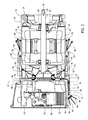
- FIG. 1 is a perspective view of an exemplary electric machine 10.
- FIG. 2 is a cross section of electric machine 10.
- electric machine 10 is an electric motor having a first end 12 and a second end 14.
- Electric machine 10 generally has a housing 16, an adaptor plate 18, a shroud 20, a motor assembly 22, a motor enclosure 24, a fan assembly 26, an electronics heat sink 28, an electronics enclosure 30, and a controller board or electronics control 32.
- Electric machine 10 also has an air cooling system 33 that facilitates cooling motor assembly 22 and electronics control 32.
- housing 16 is generally defined by adaptor plate 18, shroud 20, and motor enclosure 24.
- Motor assembly 22 generally includes a stator 34 and a rotor 36 coupled to a shaft 38.
- a plurality of permanent magnets 40 are coupled to rotor 36 in any suitable configuration that enable motor assembly 22 to function as described herein.
- stator 34 is oriented adjacent rotor 36 in an axial flux configuration.
- stator 34 may be oriented at least partially surrounding rotor 36 in a radial flux configuration.
- motor assembly 22 may include a motor heat sink (not shown) to facilitate cooling motor assembly 22.
- fan assembly 26 generally includes a fan inlet 54 and a fan 50 coupled to a shaft first end 52.
- a shaft second end 56 extends from housing 16 for coupling to a component (not shown) to be driven by rotating shaft 38, for example, a pump.
- rotor 36 is rotatable within housing 16 and, more specifically, rotor 36 is rotatable within motor enclosure 24.
- Rotor 36 is driven by stator 34, which is controlled by electronics control 32.
- electronics control 32 acts as a sinusoidal or trapezoidal electronics control for stator 34.
- electronics enclosure 30 is coupled to shroud 20 on first end 12 of housing 16.
- electronics enclosure 30 couples to an adapter piece or mount (not shown) that defines a space between shroud 20 and electronics enclosure 30.
- electronics enclosure 30 is positioned in a shroud cavity 58 such that an exterior surface 60 of electronics enclosure 30 is spaced from an interior surface 62 of shroud 20.
- Electronics enclosure 30 is coupled to shroud 20 such that electronics enclosure 30 is in-line with motor assembly 22 and fan 50. Fan 50 is positioned between electronics enclosure 30 and motor assembly 22.
- Electronics enclosure 30 includes an inner cavity 64 defined by a controller cup 66 and a controller cover 68.
- Electronics control 32 is mounted within electronics enclosure 30 and facilitates control of motor assembly 22.
- Electronics enclosure 30 is substantially air-tight and inner cavity 64 is substantially thermally isolated from other portions of electric machine 10.
- inner cavity 64 is substantially thermally isolated from motor enclosure 24 to prevent transfer of thermal energy to electronics control 32, which directly affects the useful lifetime of electric machine 10.
- Electronics control 32 is thermally coupled to electronics heat sink 28, which facilitates removal of thermal energy generated by electronics control 32 from electronics enclosure 30.
- electronics heat sink 28 includes a body portion 72 having a plurality of generally ribbed heat fins 74 extending therefrom.
- heat fins 74 have any suitable shape that enables electronics heat sink 28 to function as described herein.
- Body portion 72 is thermally coupled to electronics control 32 and transfers thermal energy generated by electronics control 32 out of inner cavity 64 via heat fins 74, as described below in more detail.
- motor enclosure 24 includes an inner cavity 76 defined by motor enclosure 24.
- Motor assembly 22 is mounted within motor enclosure 24 and shaft first end 52 extends through an aperture 78 defined in motor enclosure 24.
- Shaft second end 56 extends through an aperture 80 defined in adaptor plate 18.
- adaptor plate 18 facilitates attachment of electric machine 10 to a system (not shown) to be driven by shaft 38.
- Aperture 80 is sealed by shaft 38 and bearings 82 such that air does not pass therethrough.
- Motor enclosure 24 is substantially air-tight and is substantially thermally isolated from other portions of electric machine 10.
- motor enclosure 24 is substantially thermally isolated from electronics enclosure 30 to prevent transfer of thermal energy to electronics control 32.
- electric machine 10 includes air cooling system 33 defined by housing 16 and electronics enclosure 30.
- Air cooling system 33 generally includes an air intake 84 and an air outlet 86 fluidly connected by an air passage 88 defined by housing 16, shroud 20, and electronics enclosure 30.
- air passage 88 facilitates a flow of cooling airflow 90 therethrough to dissipate heat from electronics heat sink 28 and motor assembly 22.
- Air passage 88 includes a passage first portion 92, a passage second portion 94, a passage third portion 96, and a passage fourth portion 98.
- heat fins 74 are oriented at least partially within passage second portion 94.
- Passage third portion 96 and passage fourth portion 98 are at least partially in flow communication with motor enclosure 24.
- Fan 50 is coupled to shaft first end 52 and is rotatably mounted at least partially within passage third portion 96. Rotation of fan 50 facilitates pulling air into air intake 84 such that the cooling airflow 90 passes through passage first portion 92 and into passage second portion 94.
- Cooling airflow 90 contacts electronics heat sink 28 and removes heat generated by electronics control 32 through electronics heat sink body portion 72 and heat fins 74. Cooling airflow 90 then passes through passage third portion 96 and passage fourth portion 98 where the cooling airflow removes heat generated by motor assembly 22.
- Heated airflow 90 is then exhausted from housing 16 through air outlet 86.
- air outlet 86 is located a suitable distance from air intake 84 to facilitate preventing hot exhaust from being drawn back into air intake 84.
- electronics heat sink 28 is positioned at least partially within air passage 88 upstream of motor assembly 22. Positioning electronics enclosure 30 external to housing 16 minimizes the radiant transfer of thermal energy between motor enclosure 24 and electronics enclosure 30 and covers fan inlet 54 to protect electric machine 10 from the environment.
- the method includes providing housing 16 having air intake 84, air outlet 86, and air passage 88 extending between air intake 84 and air outlet 86.
- Motor enclosure 24 and electronics enclosure 30 are substantially thermally isolated from each other.
- Motor assembly 22 is coupled within motor enclosure 24 and electronics control 32 is coupled within electronics enclosure 30.
- Motor assembly 22 is positioned at least partially within air passage 88.
- Electronics heat sink 28 is thermally coupled to electronics control 32 and is positioned at least partially within air passage 88 upstream of motor assembly 22.
- Fan 50 is rotatably mounted within air passage 88 to shaft 38 downstream of electronics heat sink 28, upstream of motor assembly 22, and generally between motor enclosure 24 and electronics enclosure 30.
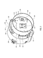
- FIG. 3 is a partial perspective view of an electronic enclosure assembly 200 that is similar to electric machine 10 shown in FIGS. 1 and 2 , except electronics enclosure assembly 200 includes a mount 202.
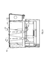
- FIG. 4 is a top perspective view of a portion of electronics enclosure assembly 200.
- FIG. 5 is a bottom perspective view of a portion of electronics enclosure assembly 200.
- mount 202 couples to a shroud 204 for covering a motor assembly (not shown).
- An electronics enclosure 206 couples to mount 202 and has an inner cavity 208 defined by a controller cup 210 and a controller cover (not shown).
- mount 202 and electronics enclosure 206 are formed as separate pieces.
- electronics enclosure 206 and mount 202 are integrally formed as a unitary piece.
- An electronics control 214 is mounted within inner cavity 208 of electronics enclosure 206. To protect electronics control 214, electronics enclosure 206 is substantially air-tight and inner cavity 208 is substantially thermally isolated from shroud 204.
- Electronics control 214 is thermally coupled to electronics heat sink 216, which facilitates removal of thermal energy generated by electronics control 214 from electronics enclosure 206.
- electronics heat sink 216 includes a body portion 218 having a plurality of heat fins 220 extending therefrom.
- Body portion 218 is thermally coupled to electronics control 214 and transfers thermal energy generated by electronics control 214 out of inner cavity 208 via heat fins 220, as described herein in more detail.
- Body portion 218 includes pads 222 in inner cavity 208 to facilitate the transfer of thermal energy from critical components of electronics control 214 to heat fins 220.
- air cooling system 224 generally includes a first air intake 226, a second air intake 228, and a third air intake 230 fluidly connected to an air passage 232 defined by electronics enclosure 206, mount 202, and shroud 204.
- air cooling system 224 includes any number of air intakes and air passages.
- air passage 232 facilitates a flow of cooling airflow therethrough to dissipate heat from electronics heat sink 216.
- Air passage 232 is defined by mount 202, a bottom surface 234 of electronics enclosure 206 and an opening 236 in mount 202. Opening 236 is aligned with an opening in shroud 204 to allow airflow into a motor housing (not shown) coupled to shroud 204.
- First air intake 226, second air intake 228, and third air intake 230 are defined by channels 238 formed in mount 202, bottom surface 234, and a side surface 240 of electronic enclosure 206.
- Channels 238 have any shape or configuration suitable to function as described.
- channels 238 have an upper portion 242 and a lower portion 244, which join at an elbow to form a substantially L-shaped cross section.
- channels 238 extend along bottom surface 234 and side surface 240 to draw air spaced from shroud 204 into first air intake 226, second air intake 228, and third air intake.
- this allows cooling system 224 to draw air into air passage 232 that has not been heated by a motor (not shown).
- channels 238 are wider near first air intake 226, second air intake 228, and third air intake 230 and narrower near opening 236.
- the narrowing width causes airflow to increase in velocity and decrease in pressure as it passes heat fins 220 and flows into opening 236. As a result, the system operates at a greater cooling efficiency while generating less noise.
- heat fins 220 are oriented at least partially within air passage 232.
- a fan (not shown) rotates to draw air into first air intake 226, second air intake 228, and third air intake 230 such that cooling airflow is directed through air passage 232.
- the cooling airflow contacts electronics heat sink 216 and removes heat generated by electronics control 214 through electronics heat sink body portion 218 and heat fins 220.
- An exemplary method of assembling electronic enclosure assembly 200 is described herein.
- the method includes providing shroud 204 and coupling mount 202 to shroud 204.
- Electronics enclosure 206 for enclosing electronics component 214 is coupled to mount 202.
- electronics enclosure 206 and mount 202 substantially thermally isolate electronics component 214 from shroud 204.
- Electronics control 214 is thermally coupled to electronics heat sink 216, which is positioned at least partially within air passage 232.
- electronics enclosure 206, mount 202, and shroud 204 define first air intake 226, second air intake 228, third air intake 230 and air passage 232.
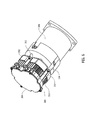
- FIG. 6 is a perspective view of an electric machine 300 that is similar to electric machine 10 shown in FIGS. 1 and 2 , except electric machine 300 includes a mount 302.
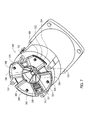
- FIG. 7 is a perspective view of electric machine 300 with an electronics enclosure 304 removed to reveal mount 302.
- mount 302 is coupled to a housing 306 by fasteners 308 through the interior of mount 302.
- electronics enclosure 304 is coupled to housing 306 by fasteners 312.
- electronics enclosure 304 couples to mount 302 instead of housing 306 and, in further embodiments, fasteners (not shown) extend through electronics enclosure 304 and mount 302 to simultaneously couple both to housing 306.
- mount 302, electronics enclosure 304, and housing 306 are coupled using mechanical fasteners, weld, adhesive, and/or any other suitable coupling means that enable electric machine 300 to function as described.
- conduit 314 extends along mount 302 to enclose wires (not shown) running from electronics enclosure 304 into housing 306. Importantly, conduit 314 facilitates positioning electronics enclosure 304 on the exterior of housing 306 and protects wires from the environment.
- Mount 302, electronics enclosure 304, and housing 306 define an air passage 316 connected to a first air intake 318, a second air intake 320, a third air intake 322, and a fourth air intake 324.
- a mount opening 326 and a fan air intake 328 are substantially aligned to facilitate airflow through air passage 316 into housing 306.
- a fan 330 is rotatably mounted in housing 306 to draw airflow into first air intake 318, second air intake 320, third air intake 322, and fourth air intake 324 and through air passage 316.
- an electronics control (not shown) is thermally coupled to electronics heat sink 332 including heat fins 334. Heat fins 334 extend around the outside of electronics enclosure 304 and are oriented at least partially within air passage 316.
- heat fins 334 are oriented in any fashion that allows airflow to cool electronics enclosure 304 as described.
- heat fins 334 can be omitted.
- An exemplary method of assembling electric machine 300 includes providing housing 306 and coupling mount 302 to housing 306.
- Electronics enclosure 304 is coupled to mount 302 and substantially thermally isolated from housing 306.
- Electronics enclosure 304, mount 302, and housing 306 are positioned to define first air intake 318, second air intake 320, third air intake 322, fourth air intake 324 and air passage 316.
- Electronics heat sink 332 is positioned at least partially within air passage 316.
- Fan 330 is rotatably mounted within housing 306 downstream of electronics heat sink 332 and in flow communication with air passage 316 to draw airflow into first air intake 318, second air intake 320, third air intake 322, and fourth air intake 324 and through air passage 316 to housing 306.
- FIG. 8 is a top view of an electric machine 400 that is similar to electric machine 10 shown in FIGS. 1 and 2 , except electric machine 400 includes a first air intake 402, a second air intake 404, and a third air intake 406 extending through an inner cavity 408 of an electronics enclosure 410.
- FIG. 9 is a cross-sectional view of electric machine 400 taken along line 9-9.
- first air intake 402, second air intake 404, and third air intake 406 are shaped as inverted cones, meaning the cross-sectional area gets smaller along the direction of airflow through the first air intake 402, second air intake 404, and third air intake 406.
- first air intake 402, second air intake 404, and third air intake 406 decreases in pressure and increases in speed with the decreasing cross-sectional area.
- this has a supercooling effect on the interior of electronics enclosure 410.
- low pressure airflow allows the system to operate more efficiently while generating minimal noise.
- electronic enclosure 410 defines any number of air intakes of varying or constant shape. For example, in one embodiment, a single intake (not shown) with a constant cross-sectional area passes through the center of electronics enclosure 410.
- the electric machine has a housing having at least one air intake, an air outlet, and an air passage between the at least one air intake and air outlet.
- Substantially air-tight enclosures for a motor assembly and electronics components are formed and coupled together.
- Heat sinks thermally couple the enclosures and the air passage such that a cooling airflow through the air passage facilitates cooling of the components within the enclosures.
- the electronics enclosure heat sink is located within the air passage upstream of the motor enclosure.
- the enclosures are substantially thermally isolated from each other at least by the air passage to prevent transfer of thermal energy between the enclosures. Accordingly, the electronics components are cooled and protected from other heat generating components of the electric machine to prevent thermal degradation and to facilitate longer life of the electronics components.
- the electric machine described herein enables cooling air to be better concentrated over hot areas of the system.
- a fan is rotatably mounted within the air passage internally within the electric machine to facilitate the cooling airflow through the air passage and to prevent external access to the moving fan. Because the fan is located internally within the electric machine (i.e., not accessible from outside the housing), the electric machine produces less audible noise pollution and prevents injuries associated with contacting the fan. In an alternative embodiment, the fan is located outside of the air passage but in flow communication with the air passage.
- Some embodiments described herein relate to electric machines including electric motors and electronic controls.
- the methods and apparatus are not limited to the specific embodiments described herein, but rather, components of apparatus and/or steps of the methods may be utilized independently and separately from other components and/or steps described herein.
- the methods may also be used in combination with any machine, and are not limited to practice with the electric machines as described herein.
- the exemplary embodiment can be implemented and utilized in connection with many other mechanical applications.
- the articles “a”, “an”, “the”, and “said” are intended to mean that there are one or more of the element(s)/component(s)/etc.
- the terms “comprising”, “including”, and “having” are intended to be inclusive and mean that there may be additional element(s)/component(s)/etc. other than the listed element(s)/component(s)/etc.
Applications Claiming Priority (1)
| Application Number | Priority Date | Filing Date | Title |
|---|---|---|---|
| US14/486,845 US9812920B2 (en) | 2014-09-15 | 2014-09-15 | Air-cooled electric machine and method of assembling the same |
Publications (2)
| Publication Number | Publication Date |
|---|---|
| EP2996225A2 true EP2996225A2 (de) | 2016-03-16 |
| EP2996225A3 EP2996225A3 (de) | 2016-09-28 |
Family
ID=54140372
Family Applications (1)
| Application Number | Title | Priority Date | Filing Date |
|---|---|---|---|
| EP15185134.2A Withdrawn EP2996225A3 (de) | 2014-09-15 | 2015-09-14 | Luftgekühlte elektrische maschine und verfahren zur montage davon |
Country Status (3)
| Country | Link |
|---|---|
| US (1) | US9812920B2 (de) |
| EP (1) | EP2996225A3 (de) |
| AU (1) | AU2015227403B2 (de) |
Cited By (2)
| Publication number | Priority date | Publication date | Assignee | Title |
|---|---|---|---|---|
| US11139722B2 (en) | 2018-03-02 | 2021-10-05 | Black & Decker Inc. | Motor having an external heat sink for a power tool |
| US20230047487A1 (en) * | 2021-08-11 | 2023-02-16 | Nidec Motor Corporation | Dual cooling fan interposed between motor controller and motor housing |
Families Citing this family (22)
| Publication number | Priority date | Publication date | Assignee | Title |
|---|---|---|---|---|
| WO2016097922A1 (en) * | 2014-12-16 | 2016-06-23 | Claudio Soresina | Hair dryer provided with an electric motor |
| US9819246B2 (en) * | 2015-01-13 | 2017-11-14 | Regal Beloit America, Inc. | Electrical machine and controller and methods of assembling the same |
| EP3427370A1 (de) | 2016-03-11 | 2019-01-16 | ITT Manufacturing Enterprises LLC | Motorbaugruppe zum antrieb einer pumpe oder drehvorrichtung mit leistungsebene mit mehrschichtiger leistung und zur steuerung der leiterplattenanordnung |
| US20170341083A1 (en) * | 2016-05-26 | 2017-11-30 | Blue Sky Innovation Group, Inc. | Grinder with enhanced cooling |
| US11028812B2 (en) * | 2016-07-27 | 2021-06-08 | Astronics Advanced Electronic Systems Corp. | Integrated brushless starter generator |
| CN109565232B (zh) * | 2016-08-05 | 2021-02-05 | 日本电产株式会社 | 马达 |
| SE540122C2 (en) * | 2016-11-08 | 2018-04-03 | Aros Electronics Ab | Electric machine with liquid cooling |
| US20180205292A1 (en) * | 2017-01-17 | 2018-07-19 | Headline Electric Co., Ltd. | Motor forcibly cooling device with rear drive assembly |
| CN108626146B (zh) * | 2017-03-17 | 2020-05-22 | 日本电产株式会社 | 送风装置以及吸尘器 |
| CN107093944A (zh) * | 2017-05-26 | 2017-08-25 | 常州合力电器有限公司 | 用于园林工具的动力装置 |
| US10608505B1 (en) * | 2018-02-09 | 2020-03-31 | Wisk Aero Llc | Cooling motor controller with a motor with duct |
| TWI661658B (zh) * | 2018-06-22 | 2019-06-01 | 群光電能科技股份有限公司 | 馬達裝置及散熱裝置 |
| DE102019103541A1 (de) * | 2018-07-06 | 2020-01-09 | Hanon Systems | Kühlmodul mit Axialgebläse für Fahrzeuge, insbesondere für Elektrofahrzeuge |
| US11374458B2 (en) * | 2018-10-24 | 2022-06-28 | Dekalb Blower Inc. | Electric motor with fluid cooling |
| DE102020200657A1 (de) * | 2019-12-06 | 2021-06-10 | Brose Fahrzeugteile SE & Co. Kommanditgesellschaft, Würzburg | Fluidgekühlte elektrische Maschine |
| US20210175773A1 (en) * | 2019-12-09 | 2021-06-10 | Weg Equipamentos Elétricos S.a. | Electronically commutated rotating electrical machine |
| US20210218304A1 (en) | 2020-01-14 | 2021-07-15 | Infinitum Electric, Inc. | Axial field rotary energy device having pcb stator and variable frequency drive |
| DE102020100865A1 (de) | 2020-01-16 | 2021-07-22 | Ebm-Papst Mulfingen Gmbh & Co. Kg | Ventilator mit einem Außenläufermotor und Kühlkanal zur Kühlung der Motorelektronik und von Motorantriebskomponenten |
| US11451156B2 (en) | 2020-01-21 | 2022-09-20 | Itt Manufacturing Enterprises Llc | Overvoltage clamp for a matrix converter |
| JP7316953B2 (ja) * | 2020-01-24 | 2023-07-28 | 株式会社やまびこ | 電動作業機 |
| US11502573B2 (en) * | 2020-04-13 | 2022-11-15 | Nidec Motor Corporation | Motor endshield promoting controller air cooling |
| US20230299643A1 (en) * | 2020-07-31 | 2023-09-21 | Safran Power Usa, Llc | Rotating machine with cooling fan |
Family Cites Families (12)
| Publication number | Priority date | Publication date | Assignee | Title |
|---|---|---|---|---|
| DE10044066A1 (de) * | 2000-09-07 | 2002-04-04 | Stribel Gmbh | Elektrischer Lüfter |
| US20060012254A1 (en) * | 2004-07-14 | 2006-01-19 | Visteon Global Technologies, Inc. | Finned rear housing for alternator |
| EP1621773B1 (de) * | 2004-07-30 | 2013-04-17 | Brose Fahrzeugteile GmbH & Co. KG, Würzburg | Kühlgebläse mit Elektromotor |
| US7687945B2 (en) | 2004-09-25 | 2010-03-30 | Bluwav Systems LLC. | Method and system for cooling a motor or motor enclosure |
| JP4480638B2 (ja) | 2005-07-04 | 2010-06-16 | Necディスプレイソリューションズ株式会社 | 貫流型強制空冷ヒートシンクおよび投写型表示装置 |
| JP5063970B2 (ja) * | 2006-10-02 | 2012-10-31 | 富士重工業株式会社 | 可搬式動力作業機 |
| US7802614B2 (en) | 2008-06-18 | 2010-09-28 | Elnar Joseph G | Electric motor cooling rings |
| US8335081B2 (en) | 2010-07-16 | 2012-12-18 | Rockwell Automation Technologies, Inc. | Heat sink cooling arrangement for multiple power electronic circuits |
| JP2013074646A (ja) | 2011-09-26 | 2013-04-22 | Toshiba Corp | 制御装置一体電動機 |
| CN202840836U (zh) | 2012-08-31 | 2013-03-27 | 中山大洋电机股份有限公司 | 一种直流无刷电机结构 |
| US9160207B2 (en) | 2012-12-25 | 2015-10-13 | Zhongshan Broad-Ocean Motor Co., Ltd. | High power brushless DC motor and control box structure with heat dissipation arrangement |
| US9467030B2 (en) * | 2013-03-15 | 2016-10-11 | Regal Beloit Australia Pty Ltd | Air-cooled electric machine and method of assembling the same |
-
2014
- 2014-09-15 US US14/486,845 patent/US9812920B2/en active Active
-
2015
- 2015-09-14 EP EP15185134.2A patent/EP2996225A3/de not_active Withdrawn
- 2015-09-15 AU AU2015227403A patent/AU2015227403B2/en active Active
Non-Patent Citations (1)
| Title |
|---|
| None |
Cited By (2)
| Publication number | Priority date | Publication date | Assignee | Title |
|---|---|---|---|---|
| US11139722B2 (en) | 2018-03-02 | 2021-10-05 | Black & Decker Inc. | Motor having an external heat sink for a power tool |
| US20230047487A1 (en) * | 2021-08-11 | 2023-02-16 | Nidec Motor Corporation | Dual cooling fan interposed between motor controller and motor housing |
Also Published As
| Publication number | Publication date |
|---|---|
| EP2996225A3 (de) | 2016-09-28 |
| AU2015227403B2 (en) | 2019-01-31 |
| US9812920B2 (en) | 2017-11-07 |
| AU2015227403A1 (en) | 2016-03-31 |
| US20160079824A1 (en) | 2016-03-17 |
Similar Documents
| Publication | Publication Date | Title |
|---|---|---|
| AU2015227403B2 (en) | Air-cooled electric machine and method of assembling the same | |
| AU2013204027B2 (en) | Air-cooled electric machine and method of assembling the same | |
| US9543807B2 (en) | Electric motor | |
| JP2014193112A (ja) | 冷却装置を伴う電気モータ | |
| JP6717904B2 (ja) | インバータ一体型モータ | |
| JP2017169338A (ja) | 電動パワーユニット | |
| JP2017530676A (ja) | 発電所のための発電機 | |
| US20080143201A1 (en) | Methods and apparatus for cooling an electric motor | |
| US20150137633A1 (en) | Ac generator | |
| JP2015192474A (ja) | 回転電機装置 | |
| MX2009000498A (es) | Instalacion de refrigeracion para una maquina electrica. | |
| BG111940A (bg) | Безчеткова електрическа машина с въздушно охлаждане | |
| US20060290214A1 (en) | Dynamo electric machine with a brushless exciter | |
| KR102400801B1 (ko) | 전동 과급기 | |
| JP2019503644A (ja) | 冷却フィンを有する回転電気機械 | |
| CN107836072A (zh) | 具有增大负压的涡轮的旋转电机 | |
| JP6890651B1 (ja) | 回転電機 | |
| JP2023545837A (ja) | 駆動装置を備えた遠心ポンプ | |
| US20230216367A1 (en) | Electric machine including an air cooling system | |
| JP2004311391A (ja) | 電磁調理器 | |
| JP2009273268A (ja) | 周波数変換装置 | |
| JP2005530946A (ja) | 発電ユニットの冷却装置 | |
| US20170179792A1 (en) | Enclosed motor utilizing recirculating coolant air | |
| JP2013150468A (ja) | 車両用回転電機 | |
| JP2023545202A (ja) | 駆動装置を備えた遠心ポンプ |
Legal Events
| Date | Code | Title | Description |
|---|---|---|---|
| PUAI | Public reference made under article 153(3) epc to a published international application that has entered the european phase |
Free format text: ORIGINAL CODE: 0009012 |
|
| AK | Designated contracting states |
Kind code of ref document: A2 Designated state(s): AL AT BE BG CH CY CZ DE DK EE ES FI FR GB GR HR HU IE IS IT LI LT LU LV MC MK MT NL NO PL PT RO RS SE SI SK SM TR |
|
| AX | Request for extension of the european patent |
Extension state: BA ME |
|
| RIC1 | Information provided on ipc code assigned before grant |
Ipc: H02K 5/20 20060101ALI20160504BHEP Ipc: H02K 9/06 20060101AFI20160504BHEP |
|
| PUAL | Search report despatched |
Free format text: ORIGINAL CODE: 0009013 |
|
| AK | Designated contracting states |
Kind code of ref document: A3 Designated state(s): AL AT BE BG CH CY CZ DE DK EE ES FI FR GB GR HR HU IE IS IT LI LT LU LV MC MK MT NL NO PL PT RO RS SE SI SK SM TR |
|
| AX | Request for extension of the european patent |
Extension state: BA ME |
|
| RIC1 | Information provided on ipc code assigned before grant |
Ipc: H02K 9/06 20060101AFI20160825BHEP Ipc: H02K 5/20 20060101ALI20160825BHEP |
|
| STAA | Information on the status of an ep patent application or granted ep patent |
Free format text: STATUS: THE APPLICATION HAS BEEN PUBLISHED |
|
| STAA | Information on the status of an ep patent application or granted ep patent |
Free format text: STATUS: THE APPLICATION IS DEEMED TO BE WITHDRAWN |
|
| 18D | Application deemed to be withdrawn |
Effective date: 20170329 |