EP2996133A1 - Pyrotechnic circuit breaker having an improved structure for accommodating a bus bar, and assembly method thereof - Google Patents
Pyrotechnic circuit breaker having an improved structure for accommodating a bus bar, and assembly method thereof Download PDFInfo
- Publication number
- EP2996133A1 EP2996133A1 EP14306381.6A EP14306381A EP2996133A1 EP 2996133 A1 EP2996133 A1 EP 2996133A1 EP 14306381 A EP14306381 A EP 14306381A EP 2996133 A1 EP2996133 A1 EP 2996133A1
- Authority
- EP
- European Patent Office
- Prior art keywords
- bus bar
- piston
- drawer
- circuit breaker
- pyrotechnic circuit
- Prior art date
- Legal status (The legal status is an assumption and is not a legal conclusion. Google has not performed a legal analysis and makes no representation as to the accuracy of the status listed.)
- Granted
Links
Images




Classifications
-
- H—ELECTRICITY
- H01—ELECTRIC ELEMENTS
- H01H—ELECTRIC SWITCHES; RELAYS; SELECTORS; EMERGENCY PROTECTIVE DEVICES
- H01H39/00—Switching devices actuated by an explosion produced within the device and initiated by an electric current
- H01H39/006—Opening by severing a conductor
-
- H—ELECTRICITY
- H01—ELECTRIC ELEMENTS
- H01H—ELECTRIC SWITCHES; RELAYS; SELECTORS; EMERGENCY PROTECTIVE DEVICES
- H01H11/00—Apparatus or processes specially adapted for the manufacture of electric switches
-
- H—ELECTRICITY
- H01—ELECTRIC ELEMENTS
- H01H—ELECTRIC SWITCHES; RELAYS; SELECTORS; EMERGENCY PROTECTIVE DEVICES
- H01H71/00—Details of the protective switches or relays covered by groups H01H73/00 - H01H83/00
- H01H71/02—Housings; Casings; Bases; Mountings
- H01H71/025—Constructional details of housings or casings not concerning the mounting or assembly of the different internal parts
Definitions
- the application relates to the field of pyrotechnic circuit breakers.
- Pyrotechnic circuit breakers are widely used for disabling an electric circuit, for instance in response to abnormal conditions of use.
- Conventional pyrotechnic circuit breakers use a bus bar acting as a conducting element, which can be cut or broken along its transverse direction into two distinct parts by a piston in order to break open the circuit by stopping the electric conduction between the two parts of the bus bar.
- a bus bar acting as a conducting element
- the invention aims at responding at least partially to this problematic, and therefore provides a pyrotechnic circuit breaker, comprising a body , an igniter, a piston and a bus bar, wherein the piston and the bus bar are adapted to be accommodated within the body, and wherein the piston comprises a cutting edge and is adapted to move along a normal direction from a raised position to a lowered position to cut a portion of the bus bar, thereby separating the bus bar into two distinct portions in order to break the electrical conduction of the bus bar, characterized in that the body comprises a longitudinal slot arranged through a longitudinal direction of the body, perpendicular to the normal direction wherein the bus bar and the longitudinal slot are configured so that the bus bar can be slidably inserted within the insertion slot.
- the pyrotechnic circuit breaker typically comprises a drawer adapted to be slidably inserted within the longitudinal slot of the body, so that once inserted in the body, the drawer and the body define the insertion slot through the body where the bus bar is slidably inserted.
- the drawer typically comprises engagement means adapted to prevent further displacement of the drawer once it is positioned within the opening of the body.
- the drawer and the bus bar can also comprise indexation means, adapted to engage the bus bar and the drawer once inserted within the body.
- the drawer comprises a receiving groove configured to allow the movement of the cutting edge of the piston through the bus bar, and wherein the receiving groove and the piston are configured so that when the piston moves and reaches its lowered position, the cutting edge of the piston is in continuous contact with a surface of the receiving groove.
- Said receiving groove has for instance a triangular shape defining two transversal surfaces of the receiving groove, so that the cutting edge of the piston comes into continuous contact with one of these transversal surfaces when the piston is in its lowered position.
- the receiving groove can be designed with other shapes and cross surfaces that are advantageously adapted to the shape of the cutting edge of the piston.
- the bus bar comprises engagement means adapted to prevent further displacement once it is positioned within the longitudinal slot of the body.
- the invention also relates to a method for assembling a pyrotechnic circuit breaker comprising the steps of:
- This method typically further comprises a preliminary step of inserting an igniter and a piston within an inner cavity of the body.
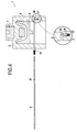
- Figures 1 to 3 disclose various views of a pyrotechnic circuit breaker 1 according to an aspect of the invention.
- the pyrotechnic circuit breaker 1 disclosed in the figures comprises
- the body 2 is adapted to accommodate the piston 5 and the igniter within an inner volume.
- the retainer 3 is typically positioned within a recess made in an outer surface of the body 2
- the piston 5 can move along a normal direction of the pyrotechnic circuit breaker 1, represented by the axis Z-Z on the drawings, between a raised position and a lowered position.
- the piston 5 remains in its raised position, such as represented for instance in figures 3 and 4 .
- the igniter 4 Upon its actuation, the igniter 4 is configured to drive the piston 5 from its raised position to its lowered position as represented for instance in figure 5 , where it separates the bus bar 6 into two distinct portions, that will arbitrarily be designated as a proximal portion and a distal portion, in order to break the electrical condition of the bus bar 6.
- the piston 5 comprises a cutting edge 51, protruding from a lower face, and adapted to come into contact with the bus bar 6, in order to cut or break the bus bar 6 along a transverse direction Y-Y, perpendicular to the normal direction Z-Z along which the piston 5 moves.
- the body comprises a longitudinal slot 21 that extends through its body, along a longitudinal direction X-X, perpendicular to the normal direction Z-Z along which the piston 5 translates.
- This longitudinal slot 21 is adapted so that the bus bar 6 can be slidably inserted through the body 2, so as to protrude from two opposite sides of the body 2 in order to establish electric conduction through the body 2 by connecting an electric circuit to both ends of the bus bar 6 that protrude from the body 2.
- Figure 4 illustrates the insertion of the bus bar 6 within the longitudinal slot 21.
- the pyrotechnic circuit breaker 1 is assembled, with the exception of the bus bar 6.
- the bus bar is then slidably inserted through the longitudinal slot 21 of the body 2, so as to protrude from two opposite sides of the body 2, as represented in figures 1 and 3 for instance.
- the whole pyrotechnic circuit breaker 1 can therefore be assembled without the bus bar 6, which can then be slidably inserted within the body 2 in order to complete the device.
- the bus bar 6 and the body 2 typically comprise indexation means, so as to ensure a proper positioning of the bus bar 6 with respect to the body 2, and to maintain the bus bar 6 within the body 2 once inserted.
- the indexation means of the bus bar 6 comprise notches 6a, 6b, 6c, 6d arranged on the sides of the bus bar 6, adapted to abut against corresponding surfaces of the body 2. These notches can be made asymmetrical, in order to define an unique way of inserting the bus bar 6 within the insertion slot, allowing to immobilize the bus bar in the direction of its insertion in the body 2
- the indexation means comprise a central blade 6e arranged along the central longitudinal axis X-X of the bus bar 6 and adapted to abut against the internal opposing sides of the body 2, allowing to immobilize the bus bar in the opposite direction of its insertion in the body 2
- the shape and the number of the said blade 6e can be modified and adapted to the design of the body 2.
- the indexation means comprise a through hole 67 arranged within the bus bar 6, and a locating pin 26 coupled with a spring 27 and mounted in a recess 28 of the body 2.
- the indexation means can comprise multiple through holes 67 and/or locating pins 26 in order to reinforce the holding in position of the bus bar 6.
- the locating pin 26 is configured so that during the insertion of the bus bar 6, the bus bar pushes the locating pin 26 back in the recess 28, and once the bus bar is in position where the through hole 67 is aligned with the locating pin 26, the locating pin 26 is pushed by the spring 27 out of the recess 28, and engages the through hole 67 of the bus bar 6, and therefore locks the bus bar 6 in position with respect to the body 2 of the pyrotechnic circuit breaker 1
- the locating pin 26 and the through hole 67 typically have a non-circular section, so that the locating pin 26 does not rotate during handling and assembly.
- FIGS 5 to 11 disclose various views of an alternative embodiment of a pyrotechnic circuit breaker 1 according to an aspect of the invention.
- the pyrotechnic circuit breaker 1 disclosed in figures 5 to 11 comprises
- the body 2 is adapted to accommodate the piston 5 and the igniter within an inner volume.
- the retainer 3 is typically positioned within a recess made in an outer surface of the body 2
- the piston 5 can move along a normal direction of the pyrotechnic circuit breaker 1, represented by the axis Z-Z on the drawings, between a raised position and a lowered position.
- the piston 5 remains in its raised position, such as represented for instance in figures 7 and 8 .
- the igniter 4 Upon its actuation, the igniter 4 is configured to drive the piston 5 from its raised position to its lowered position as represented for instance in figure 9 , where it separates the bus bar 6 into two distinct portions, that will arbitrarily be designated as a proximal portion and a distal portion, in order to break the electrical condition of the bus bar 6.
- the piston 5 comprises a cutting edge 51, protruding from a lower face, and adapted to come into contact with the bus bar 6, in order to cut or break the bus bar 6 along a transverse direction Y-Y, perpendicular to the normal direction Z-Z along which the piston 5 moves.
- the body comprises a longitudinal slot 21 that extends through its body, along a longitudinal direction X-X, perpendicular to the normal direction Z-Z along which the piston 5 translates.
- the pyrotechnic circuit breaker 1 comprises a drawer 7, configured to be inserted within the longitudinal slot 21 of the body 2, typically so as to fit within the body 2, and to define an insertion slot between the body 2 and the drawer 7, adapted to receive the bus bar 6.
- the longitudinal slot 21 therefore has greater dimensions than in the embodiment disclosed with respect to figures 1 to 4 , so as to accommodate both the drawer 7 and the bus bar 6.
- Figures 10 and 11 illustrate the successive insertions of the drawer 7 and the bus bar 6 within the longitudinal slot 21 of the body 2.
- the drawer 7 is first inserted within the longitudinal slot 21 of the body 2, so that it is retained within the body, for instance by notches and/or indentations arranged on the drawer 7 and on the body 2.
- the drawer 7 comprises a notch 73 on one end which abuts against an insertion stop 23 of the body once the drawer 7 is fully inserted within the body 2, and a protrusion 74 which acts as anti-return means in order to prevent an involuntary removal of the drawer 7 once fully inserted within the body 2.
- This protrusion 74 abuts against a removal stop 24 of the body opposite the insertion stop 23 of the body 2.
- the drawer 7 typically has a height which is less than the height of the longitudinal slot 21 thereby forming the insertion slot between the drawer 7 and the body 2, and also enabling to insert the drawer 7 within the longitudinal slot of the body 2 even though the drawer 7 comprises protrusions 74.
- the drawer 7 and the body 2 define an insertion slot adapted to receive the bus bar 6.
- the bus bar 6 is then slidably inserted in the insertion slot, as illustrated in figure 11 , in order to be positioned through the body 2, as represented in figures 5 and 7 for instance, so as to protrude from two opposite sides of the body 2.
- the bus bar 6 typically comprises indexation means, in order to lock its position with respect to the drawer 7 and the body 2 once inserted within the insertion slot.
- indexation means can either immobilize the bus bar 6 with respect to the drawer 7 and the body, or limit its displacement to a translation according to a single direction, opposite to the direction from which it was inserted within the insertion slot.
- the indexation means of the bus bar 6 comprise notches 6a, 6b, 6c, 6d arranged on the sides of the bus bar 6, adapted to abut against corresponding surfaces of the body 2 and/or of the drawer 7. These notches can be made asymmetrical, in order to define an unique way of inserting the bus bar 6 within the insertion slot 2 allowing to immobilize the bus bar in the the direction of its insertion in the body 2
- the indexation means comprise a central blade 6e arranged along the central longitudinal axis X-X of the bus bar 6 and adapted to abut against the internal opposing side of the body 2, allowing to immobilize the bus bar in the opposite direction of its insertion in the body 2
- the shape and the number of the said blade 6e can be modified and adapted to the design of the body 2.
- the drawer 7 can be adapted in order to modify the dimensions and shape of the insertion slot, and therefore enables to adapt the body 2 of the pyrotechnic circuit breaker to various types and shapes of bus bars 6.
- the pyrotechnical circuit breaker 1 as disclosed can therefore be adapted to various types and shapes of bus bars 6, while only requiring the change of a single component, i.e. the drawer 7.
- the indexation means comprise a through hole 67 arranged within the bus bar 6, and a locating pin 76 coupled with a spring 77 and mounted in a recess 78 of the drawer 7.
- the indexation means can comprise multiple through holes 67 and/or locating pins 76 in order to reinforce the holding in position of the bus bar 6.
- the locating pin 76 is configured so that during the insertion of the bus bar 6, the bus bar pushes the locating pin 76 back in the recess 78, and once the bus bar 6 is in position where the through hole 67 is aligned with the locating pin 76, the locating pin 76 is pushed by the spring 77 out of the recess 78, and engages the through hole 67 of the bus bar 6, and therefore locks the bus bar 6 in position with respect to the drawer 7 and to the body 2 of the pyrotechnic circuit breaker 1
- the locating pin 76 and the through hole 67 typically have a non-circular section, so that the locating pin 76 does not rotate during handling and assembly.
- the drawer 7 typically comprises a receiving groove 72 arranged along the transversal direction Y-Y, configured to receive the cut or broken portion of the bus bar 6, and to allow the movement of the cutting edge 51 of the piston 5 through the bus bar 6.
- the drawer comprises a receiving groove 72 having a triangular or globally triangular section.
- the cutting edge 51 of the piston 5 comes into contact with a transversal surface of the receiving groove 72 once the bus bar 6 is cut.
- the receiving groove 72 is typically configured so that once the piston 5 moves and reaches its lowered position its lowered position, the cutting edge 51 is in continuous contact with a surface of the receiving groove 72.
- This continuous contact between the cutting edge 51 of the piston and the drawer 7 enables to isolate the two portions of the bus bar 6 from each other once it has been cut, and thereby improves the electrical insulation between these two portions of the bus bar 6 for reliably breaking the associated circuit.
- Such continuous contact between the piston 5 and the drawer 7 enables to shut down potential arching which can occur during bus bar opening between the two portions of the bus bar 6 once the bus bar 6 is cut.
- the shape of the receiving groove 72 is typically adapted to be the negative or complementary of the shape of the cutting edge 51 of the piston 5, and can be provided with sealing means along one of its surfaces adapted to come in contact with the cutting edge 51 of the piston 5 to ensure a proper contact.
Landscapes
- Engineering & Computer Science (AREA)
- Manufacturing & Machinery (AREA)
- Breakers (AREA)
- Automotive Seat Belt Assembly (AREA)
- Circuit Breakers (AREA)
- Train Traffic Observation, Control, And Security (AREA)
Abstract
characterized in that
the body (2) comprises a longitudinal slot (21) arranged through a longitudinal direction (X-X) of the body (2), perpendicular to the normal direction (Z-Z), wherein the bus bar (6) and the longitudinal slot (21) are configured so that the bus bar (6) can be slidably inserted within the insertion slot (21).
Description
- The application relates to the field of pyrotechnic circuit breakers.
- Pyrotechnic circuit breakers are widely used for disabling an electric circuit, for instance in response to abnormal conditions of use.
- Conventional pyrotechnic circuit breakers use a bus bar acting as a conducting element, which can be cut or broken along its transverse direction into two distinct parts by a piston in order to break open the circuit by stopping the electric conduction between the two parts of the bus bar. In the present text, we will refer to the cutting of the bus bar by the piston, to designate either its cutting or its breaking by the piston.
- In such pyrotechnic circuit breakers, a recurring issue resides in the assembly of the bus bar, which is usually integrated during the assembly of the pyrotechnic circuit breakers, which are provided as a whole together with their associated bus bar by overmoulding or bolting components around the bus bar.
- Furthermore, an additional recurring issue resides in the compatibility of the body of the circuit breaker with various models of bus bar. Conventional circuit breakers are indeed provided with specific bus bar, thereby preventing their use with bus bars that have distinct dimensions such as thickness and width.
- The invention aims at responding at least partially to this problematic, and therefore provides a pyrotechnic circuit breaker, comprising a body , an igniter, a piston and a bus bar, wherein the piston and the bus bar are adapted to be accommodated within the body, and wherein the piston comprises a cutting edge and is adapted to move along a normal direction from a raised position to a lowered position to cut a portion of the bus bar, thereby separating the bus bar into two distinct portions in order to break the electrical conduction of the bus bar,
characterized in that
the body comprises a longitudinal slot arranged through a longitudinal direction of the body, perpendicular to the normal direction wherein the bus bar and the longitudinal slot are configured so that the bus bar can be slidably inserted within the insertion slot. - The pyrotechnic circuit breaker typically comprises a drawer adapted to be slidably inserted within the longitudinal slot of the body, so that once inserted in the body, the drawer and the body define the insertion slot through the body where the bus bar is slidably inserted.
- The drawer typically comprises engagement means adapted to prevent further displacement of the drawer once it is positioned within the opening of the body.
- The drawer and the bus bar can also comprise indexation means, adapted to engage the bus bar and the drawer once inserted within the body.
- According to a preferred embodiment of the invention, the drawer comprises a receiving groove configured to allow the movement of the cutting edge of the piston through the bus bar, and wherein the receiving groove and the piston are configured so that when the piston moves and reaches its lowered position, the cutting edge of the piston is in continuous contact with a surface of the receiving groove.
- Said receiving groove has for instance a triangular shape defining two transversal surfaces of the receiving groove, so that the cutting edge of the piston comes into continuous contact with one of these transversal surfaces when the piston is in its lowered position.
- The receiving groove can be designed with other shapes and cross surfaces that are advantageously adapted to the shape of the cutting edge of the piston.
- The bus bar comprises engagement means adapted to prevent further displacement once it is positioned within the longitudinal slot of the body.
- The invention also relates to a method for assembling a pyrotechnic circuit breaker comprising the steps of:
- inserting a drawer within a longitudinal slot of a body of the pyrotechnic circuit breaker, so as to define an insertion slot between the body and the drawer, and then
- inserting a bus bar through the body of the pyrotechnic circuit breaker.
- This method typically further comprises a preliminary step of inserting an igniter and a piston within an inner cavity of the body.
- Other features, aims and advantages of the invention will be detailed in the following description, which is purely illustrative and should not be interpreted in a limiting way, and which should be read in view of the enclosed drawings, wherein:
-
Figures 1 and2 disclose two views of a pyrotechnic circuit breaker according to an aspect of the invention, respectively an assembled view and an exploded view; -
Figure 3 is a cross section view of the pyrotechnic circuit breaker disclosed infigures 1 and2 ; -
Figure 4 illustrates the assembly of the bus bar within the body of the pyrotechnic circuit breaker; -
Figures 5 and6 disclose two views of a pyrotechnic circuit breaker according to another aspect of the invention, respectively an assembled view and an exploded view; -
Figures 7 and8 are cross section views of the pyrotechnic circuit breaker disclosed infigures 5 and6 ; -
Figure 9 is a cross section view of the pyrotechnic circuit breaker disclosed infigures 5 and6 with a cut bus bar and an embodiment of locking means; -
Figures 10 and 11 illustrate the steps of assembly of the drawer and the bus bar of the pyrotechnic circuit breaker disclosed infigure 9 . - In the various figures, the common elements are identified using identical numeral references.
-
Figures 1 to 3 disclose various views of a pyrotechnic circuit breaker 1 according to an aspect of the invention. - The pyrotechnic circuit breaker 1 disclosed in the figures comprises
- a
body 2, - a
retainer 3 - an
igniter 4, - a
piston 5, and - a
bus bar 6. - The
body 2 is adapted to accommodate thepiston 5 and the igniter within an inner volume. Theretainer 3 is typically positioned within a recess made in an outer surface of thebody 2 - The
piston 5 can move along a normal direction of the pyrotechnic circuit breaker 1, represented by the axis Z-Z on the drawings, between a raised position and a lowered position. - As long as the
igniter 4 has not been used, thepiston 5 remains in its raised position, such as represented for instance infigures 3 and4 . - Upon its actuation, the
igniter 4 is configured to drive thepiston 5 from its raised position to its lowered position as represented for instance infigure 5 , where it separates thebus bar 6 into two distinct portions, that will arbitrarily be designated as a proximal portion and a distal portion, in order to break the electrical condition of thebus bar 6. - To achieve the cut of the bus bar, the
piston 5 comprises acutting edge 51, protruding from a lower face, and adapted to come into contact with thebus bar 6, in order to cut or break thebus bar 6 along a transverse direction Y-Y, perpendicular to the normal direction Z-Z along which thepiston 5 moves. - The body comprises a
longitudinal slot 21 that extends through its body, along a longitudinal direction X-X, perpendicular to the normal direction Z-Z along which thepiston 5 translates. - This
longitudinal slot 21 is adapted so that thebus bar 6 can be slidably inserted through thebody 2, so as to protrude from two opposite sides of thebody 2 in order to establish electric conduction through thebody 2 by connecting an electric circuit to both ends of thebus bar 6 that protrude from thebody 2. -
Figure 4 illustrates the insertion of thebus bar 6 within thelongitudinal slot 21. - As represented in this figure, the pyrotechnic circuit breaker 1 is assembled, with the exception of the
bus bar 6. The bus bar is then slidably inserted through thelongitudinal slot 21 of thebody 2, so as to protrude from two opposite sides of thebody 2, as represented infigures 1 and 3 for instance. - The whole pyrotechnic circuit breaker 1 can therefore be assembled without the
bus bar 6, which can then be slidably inserted within thebody 2 in order to complete the device. - This enables to provide the
bus bar 6 independently from the other components of the pyrotechnic circuit breaker 1, contrary to conventional pyrotechnic circuit breakers that are usually provided together with their associated bus bar, which is integrated within the body during its assembly. - The
bus bar 6 and thebody 2 typically comprise indexation means, so as to ensure a proper positioning of thebus bar 6 with respect to thebody 2, and to maintain thebus bar 6 within thebody 2 once inserted. - In the embodiment disclosed in
figure 2 , the indexation means of thebus bar 6 comprisenotches bus bar 6, adapted to abut against corresponding surfaces of thebody 2. These notches can be made asymmetrical, in order to define an unique way of inserting thebus bar 6 within the insertion slot, allowing to immobilize the bus bar in the direction of its insertion in thebody 2 - In the embodiment disclosed in the
figures 2 and3 , the indexation means comprise acentral blade 6e arranged along the central longitudinal axis X-X of thebus bar 6 and adapted to abut against the internal opposing sides of thebody 2, allowing to immobilize the bus bar in the opposite direction of its insertion in thebody 2 - The shape and the number of the said
blade 6e can be modified and adapted to the design of thebody 2. - In the embodiment disclosed in
figure 4 , the indexation means comprise a throughhole 67 arranged within thebus bar 6, and a locatingpin 26 coupled with aspring 27 and mounted in a recess 28 of thebody 2. The indexation means can comprise multiple throughholes 67 and/or locatingpins 26 in order to reinforce the holding in position of thebus bar 6. - The locating
pin 26 is configured so that during the insertion of thebus bar 6, the bus bar pushes the locatingpin 26 back in the recess 28, and once the bus bar is in position where the throughhole 67 is aligned with the locatingpin 26, the locatingpin 26 is pushed by thespring 27 out of the recess 28, and engages the throughhole 67 of thebus bar 6, and therefore locks thebus bar 6 in position with respect to thebody 2 of the pyrotechnic circuit breaker 1 - The locating
pin 26 and the throughhole 67 typically have a non-circular section, so that the locatingpin 26 does not rotate during handling and assembly. -
Figures 5 to 11 disclose various views of an alternative embodiment of a pyrotechnic circuit breaker 1 according to an aspect of the invention. The pyrotechnic circuit breaker 1 disclosed infigures 5 to 11 comprises - a
body 2, - a
retainer 3 - an
igniter 4, - a
piston 5, - a
bus bar 6, and - a
drawer 7. - As already described in reference to
figures 1 to 3 , thebody 2 is adapted to accommodate thepiston 5 and the igniter within an inner volume. Theretainer 3 is typically positioned within a recess made in an outer surface of thebody 2 - The
piston 5 can move along a normal direction of the pyrotechnic circuit breaker 1, represented by the axis Z-Z on the drawings, between a raised position and a lowered position. - As long as the
igniter 4 has not been used, thepiston 5 remains in its raised position, such as represented for instance infigures 7 and8 . - Upon its actuation, the
igniter 4 is configured to drive thepiston 5 from its raised position to its lowered position as represented for instance infigure 9 , where it separates thebus bar 6 into two distinct portions, that will arbitrarily be designated as a proximal portion and a distal portion, in order to break the electrical condition of thebus bar 6. - To achieve the cut of the bus bar, the
piston 5 comprises acutting edge 51, protruding from a lower face, and adapted to come into contact with thebus bar 6, in order to cut or break thebus bar 6 along a transverse direction Y-Y, perpendicular to the normal direction Z-Z along which thepiston 5 moves. - The body comprises a
longitudinal slot 21 that extends through its body, along a longitudinal direction X-X, perpendicular to the normal direction Z-Z along which thepiston 5 translates. - In this embodiment, the pyrotechnic circuit breaker 1 comprises a
drawer 7, configured to be inserted within thelongitudinal slot 21 of thebody 2, typically so as to fit within thebody 2, and to define an insertion slot between thebody 2 and thedrawer 7, adapted to receive thebus bar 6. - In this embodiment, the
longitudinal slot 21 therefore has greater dimensions than in the embodiment disclosed with respect tofigures 1 to 4 , so as to accommodate both thedrawer 7 and thebus bar 6. -
Figures 10 and 11 illustrate the successive insertions of thedrawer 7 and thebus bar 6 within thelongitudinal slot 21 of thebody 2. - As illustrated in
figure 10 , thedrawer 7 is first inserted within thelongitudinal slot 21 of thebody 2, so that it is retained within the body, for instance by notches and/or indentations arranged on thedrawer 7 and on thebody 2. - In the illustrated embodiment, the
drawer 7 comprises anotch 73 on one end which abuts against aninsertion stop 23 of the body once thedrawer 7 is fully inserted within thebody 2, and aprotrusion 74 which acts as anti-return means in order to prevent an involuntary removal of thedrawer 7 once fully inserted within thebody 2. Thisprotrusion 74 abuts against aremoval stop 24 of the body opposite theinsertion stop 23 of thebody 2. - The
drawer 7 typically has a height which is less than the height of thelongitudinal slot 21 thereby forming the insertion slot between thedrawer 7 and thebody 2, and also enabling to insert thedrawer 7 within the longitudinal slot of thebody 2 even though thedrawer 7 comprisesprotrusions 74. - Other means can be used in order to maintain the
drawer 7 within thebody 2 once inserted, for instance flexible tongues or blades can be made in thedrawer 7, and configured so that they are bent during insertion of thedrawer 7 within thebody 2, and extend within thebody 2 once thedrawer 7 is inserted to prevent the removal of thedrawer 7. - Once the
drawer 7 is fully inserted and maintained in position within thebody 2, thedrawer 7 and thebody 2 define an insertion slot adapted to receive thebus bar 6. - The
bus bar 6 is then slidably inserted in the insertion slot, as illustrated infigure 11 , in order to be positioned through thebody 2, as represented infigures 5 and 7 for instance, so as to protrude from two opposite sides of thebody 2. - In the same way as for the
drawer 7, thebus bar 6 typically comprises indexation means, in order to lock its position with respect to thedrawer 7 and thebody 2 once inserted within the insertion slot. - These indexation means can either immobilize the
bus bar 6 with respect to thedrawer 7 and the body, or limit its displacement to a translation according to a single direction, opposite to the direction from which it was inserted within the insertion slot. - In the embodiment disclosed in
figure 6 , the indexation means of thebus bar 6comprise notches bus bar 6, adapted to abut against corresponding surfaces of thebody 2 and/or of thedrawer 7. These notches can be made asymmetrical, in order to define an unique way of inserting thebus bar 6 within theinsertion slot 2 allowing to immobilize the bus bar in the the direction of its insertion in thebody 2 - In the embodiment disclosed in the
figures 6 and7 , the indexation means comprise acentral blade 6e arranged along the central longitudinal axis X-X of thebus bar 6 and adapted to abut against the internal opposing side of thebody 2, allowing to immobilize the bus bar in the opposite direction of its insertion in thebody 2 - The shape and the number of the said
blade 6e can be modified and adapted to the design of thebody 2. - The
drawer 7 can be adapted in order to modify the dimensions and shape of the insertion slot, and therefore enables to adapt thebody 2 of the pyrotechnic circuit breaker to various types and shapes of bus bars 6. - The pyrotechnical circuit breaker 1 as disclosed can therefore be adapted to various types and shapes of
bus bars 6, while only requiring the change of a single component, i.e. thedrawer 7. - In the embodiment disclosed in
figures 9 to 11 , the indexation means comprise a throughhole 67 arranged within thebus bar 6, and a locatingpin 76 coupled with aspring 77 and mounted in arecess 78 of thedrawer 7. The indexation means can comprise multiple throughholes 67 and/or locatingpins 76 in order to reinforce the holding in position of thebus bar 6. - The locating
pin 76 is configured so that during the insertion of thebus bar 6, the bus bar pushes the locatingpin 76 back in therecess 78, and once thebus bar 6 is in position where the throughhole 67 is aligned with the locatingpin 76, the locatingpin 76 is pushed by thespring 77 out of therecess 78, and engages the throughhole 67 of thebus bar 6, and therefore locks thebus bar 6 in position with respect to thedrawer 7 and to thebody 2 of the pyrotechnic circuit breaker 1 - The locating
pin 76 and the throughhole 67 typically have a non-circular section, so that the locatingpin 76 does not rotate during handling and assembly. - As illustrated in the drawings, and more specifically in
figure 9 , thedrawer 7 typically comprises a receivinggroove 72 arranged along the transversal direction Y-Y, configured to receive the cut or broken portion of thebus bar 6, and to allow the movement of thecutting edge 51 of thepiston 5 through thebus bar 6. - In the illustrated embodiment, the drawer comprises a receiving
groove 72 having a triangular or globally triangular section. Upon its movement from the raised position to the lowered position, thecutting edge 51 of thepiston 5 comes into contact with a transversal surface of the receivinggroove 72 once thebus bar 6 is cut. The receivinggroove 72 is typically configured so that once thepiston 5 moves and reaches its lowered position its lowered position, thecutting edge 51 is in continuous contact with a surface of the receivinggroove 72. - This continuous contact between the cutting
edge 51 of the piston and thedrawer 7 enables to isolate the two portions of thebus bar 6 from each other once it has been cut, and thereby improves the electrical insulation between these two portions of thebus bar 6 for reliably breaking the associated circuit. Such continuous contact between thepiston 5 and thedrawer 7 enables to shut down potential arching which can occur during bus bar opening between the two portions of thebus bar 6 once thebus bar 6 is cut. - The shape of the receiving
groove 72 is typically adapted to be the negative or complementary of the shape of thecutting edge 51 of thepiston 5, and can be provided with sealing means along one of its surfaces adapted to come in contact with thecutting edge 51 of thepiston 5 to ensure a proper contact.
Claims (9)
- A pyrotechnic circuit breaker (1), comprising a body (2), an igniter (4), a piston (5) and a bus bar (6), wherein the piston (5) and the bus bar (6) are adapted to be accommodated within the body (2), and wherein the piston (5) comprises a cutting edge (51) and is adapted to move along a normal direction (Z-Z) from a raised position to a lowered position to cut a portion of the bus bar (6), thereby separating the bus bar (6) into two distinct portions in order to break the electrical conduction of the bus bar (6),
characterized in that
the body (2) comprises a longitudinal slot (21) arranged through a longitudinal direction (X-X) of the body (2), perpendicular to the normal direction (Z-Z), wherein the bus bar (6) and the longitudinal slot (21) are configured so that the bus bar (6) can be slidably inserted within the insertion slot (21). - The pyrotechnic circuit breaker (1) of claim 1, further comprising a drawer (7) adapted to be slidably inserted within the longitudinal slot (21) of the body (2), so that once inserted in the body (2), the drawer (7) and the body (2) define an insertion slot through the body (2) where the bus bar (6) is slidably inserted.
- The pyrotechnic circuit breaker (1) of claim 2, wherein the drawer (7) and the body (2) define an insertion slot through the body (2) configured so that the bus bar (6) is slidably inserted within the insertion slot.
- The pyrotechnic circuit breaker (1) of claim 2 or 3, wherein the drawer (7) comprises engagement means adapted to prevent further displacement of the drawer (7) once it is positioned within the opening of the body (2).
- The pyrotechnic circuit breaker (1) of any one of claims 2 to 4, wherein the drawer (7) and the bus bar (6) comprise indexation means adapted to engage the bus bar (6) and the drawer (7) once inserted within the body (2).
- The pyrotechnic circuit breaker (1) of any one of claims 2 to 5, wherein the drawer (7) comprises a receiving groove (72) configured to allow the movement of the cutting edge (51) of the piston (5) through the bus bar (6), and wherein the receiving groove (72) and the piston (5) are configured so that when the piston (5) is in its lowered position, the cutting edge (51) of the piston (5) is in continuous contact with a surface of the receiving groove (72).
- The pyrotechnic circuit breaker (1) of claim 6, wherein said receiving groove (72) has a triangular shape defining two transversal surfaces of the receiving groove (72), so that the cutting edge (51) of the piston (5) comes into continuous contact with one of these transversal surfaces when the piston (5) is in its lowered position.
- The pyrotechnic circuit breaker (1) of claim 6 or 7, wherein said receiving groove (72) has a surface which shape is complementary to the shape of the cutting edge (51) of the piston (5).
- The pyrotechnic circuit breaker (1) of claim 2 to 8, wherein the bus bar (6) comprises engagement means (6a, 6b, 6c, 6d, 6e) adapted to prevent further displacement once it is positioned within the longitudinal slot (21) of the body (2).
Priority Applications (5)
| Application Number | Priority Date | Filing Date | Title |
|---|---|---|---|
| EP14306381.6A EP2996133B8 (en) | 2014-09-09 | 2014-09-09 | Pyrotechnic circuit breaker having an improved structure for accommodating a bus bar, and assembly method thereof |
| US15/506,926 US10128074B2 (en) | 2014-09-09 | 2015-09-08 | Pyrotechnic circuit breaker having an improved structure for accommodating a bus bar, and assembly method thereof |
| CN201580047078.1A CN107077994B (en) | 2014-09-09 | 2015-09-08 | Pyrotechnic circuit breaker with improved structure for accommodating bus bars, and method of assembling the same |
| JP2017532212A JP6692818B2 (en) | 2014-09-09 | 2015-09-08 | Pyrotechnic circuit breaker with improved structure for accommodating busbars and method of assembly thereof |
| PCT/EP2015/070511 WO2016038043A1 (en) | 2014-09-09 | 2015-09-08 | Pyrotechnic circuit breaker having an improved structure for accommodating a bus bar, and assembly method thereof |
Applications Claiming Priority (1)
| Application Number | Priority Date | Filing Date | Title |
|---|---|---|---|
| EP14306381.6A EP2996133B8 (en) | 2014-09-09 | 2014-09-09 | Pyrotechnic circuit breaker having an improved structure for accommodating a bus bar, and assembly method thereof |
Publications (3)
| Publication Number | Publication Date |
|---|---|
| EP2996133A1 true EP2996133A1 (en) | 2016-03-16 |
| EP2996133B1 EP2996133B1 (en) | 2017-05-10 |
| EP2996133B8 EP2996133B8 (en) | 2017-08-23 |
Family
ID=52232048
Family Applications (1)
| Application Number | Title | Priority Date | Filing Date |
|---|---|---|---|
| EP14306381.6A Active EP2996133B8 (en) | 2014-09-09 | 2014-09-09 | Pyrotechnic circuit breaker having an improved structure for accommodating a bus bar, and assembly method thereof |
Country Status (5)
| Country | Link |
|---|---|
| US (1) | US10128074B2 (en) |
| EP (1) | EP2996133B8 (en) |
| JP (1) | JP6692818B2 (en) |
| CN (1) | CN107077994B (en) |
| WO (1) | WO2016038043A1 (en) |
Cited By (3)
| Publication number | Priority date | Publication date | Assignee | Title |
|---|---|---|---|---|
| FR3051281A1 (en) * | 2016-05-16 | 2017-11-17 | Herakles | ELECTRICAL CUTTING DEVICE AND SECURE ELECTRICAL SYSTEM COMPRISING SUCH A DEVICE |
| CN110226212A (en) * | 2016-12-20 | 2019-09-10 | 阿丽亚娜集团联合股份公司 | Pyrotechnics short-circuiting device |
| DE102018204105A1 (en) | 2018-03-16 | 2019-09-19 | Leoni Bordnetz-Systeme Gmbh | Safety device and set of several types of safety devices |
Families Citing this family (14)
| Publication number | Priority date | Publication date | Assignee | Title |
|---|---|---|---|---|
| EP3401940B1 (en) | 2017-05-09 | 2021-06-23 | ArianeGroup SAS | Pyrotechnic circuit breaker |
| JP6962756B2 (en) | 2017-09-15 | 2021-11-05 | 株式会社ダイセル | Electric circuit breaker |
| FR3071660B1 (en) | 2017-09-26 | 2019-10-11 | Arianegroup Sas | PYROTECHNIC CUTTING DEVICE |
| FR3073664B1 (en) | 2017-11-14 | 2019-12-06 | Arianegroup Sas | PYROTECHNIC CUT-OFF DEVICE |
| FR3081255B1 (en) * | 2018-05-21 | 2020-05-29 | Arianegroup Sas | PYROTECHNIC CUT-OFF DEVICE |
| FR3085534B1 (en) | 2018-09-05 | 2021-07-09 | Arianegroup Sas | PYROTECHNICAL CUTTING DEVICE |
| DE102019205281B4 (en) * | 2019-04-11 | 2022-08-04 | Leoni Bordnetz-Systeme Gmbh | Pyrotechnic fuse element and method for producing a pyrotechnic fuse element |
| FR3099287B1 (en) | 2019-07-25 | 2023-06-30 | Arianegroup Sas | Pyrotechnic cut-off device |
| GB2592878A (en) * | 2019-09-05 | 2021-09-15 | Eaton Intelligent Power Ltd | Switch with actuator |
| FR3111008B1 (en) * | 2020-05-28 | 2022-09-23 | Arianegroup Sas | Plasma chamber cut-off device |
| WO2023032843A1 (en) * | 2021-09-03 | 2023-03-09 | デクセリアルズ株式会社 | Protective element |
| CN114899053B (en) * | 2022-06-15 | 2026-05-01 | 西安中熔电气股份有限公司 | Excitation protection device |
| JP7426618B1 (en) * | 2022-12-23 | 2024-02-02 | パナソニックIpマネジメント株式会社 | Shutoff device |
| CN120457511A (en) * | 2022-12-23 | 2025-08-08 | 松下知识产权经营株式会社 | Cutting device |
Citations (4)
| Publication number | Priority date | Publication date | Assignee | Title |
|---|---|---|---|---|
| US4224487A (en) * | 1978-02-23 | 1980-09-23 | Simonsen Bent P | Fast acting explosive circuit interrupter |
| US20040221638A1 (en) * | 2003-02-04 | 2004-11-11 | Uwe Brede | Pyromechanical cutting element |
| US20100218659A1 (en) * | 2007-09-27 | 2010-09-02 | Tetsuya Ukon | Cutting apparatus, breaker, contactor, and electrical circuit breaker |
| US20130056344A1 (en) * | 2010-03-15 | 2013-03-07 | Herakles | Electric circuit breaker with pyrotechnic actuation |
Family Cites Families (21)
| Publication number | Priority date | Publication date | Assignee | Title |
|---|---|---|---|---|
| US2936331A (en) * | 1957-02-04 | 1960-05-10 | Allis Chalmers Mfg Co | Conductor support employing resin |
| US3003045A (en) * | 1958-09-08 | 1961-10-03 | Clyde L Tichenor | Electrical switching device |
| AT252766B (en) * | 1963-10-22 | 1967-03-10 | Bofors Ab | Circuit for the optional actuation of a part or all of a group of trace bullets in one floor or the like. |
| US3393605A (en) * | 1967-08-31 | 1968-07-23 | Paul E. Parnell | Explosively actuated device for high pressure environment |
| FR2200770A5 (en) * | 1972-06-26 | 1974-04-19 | France Etat | |
| DE2345196A1 (en) * | 1973-09-07 | 1975-03-20 | Univ Moskovsk | SWITCH WITH EXPLOSIVE EFFECT |
| US5227587A (en) * | 1991-05-13 | 1993-07-13 | Emerson Electric Co. | Hermetic assembly arrangement for a current conducting pin passing through a housing wall |
| US5535842A (en) * | 1993-03-05 | 1996-07-16 | Volkswagen Ag | Safety arrangement for collision-related disconnection of an electrical energy source from a motor vehicle supply circuit |
| DE19503809B4 (en) * | 1995-02-06 | 2005-01-20 | Bayerische Motoren Werke Ag | Safety device for a power line in vehicles |
| JP3426508B2 (en) * | 1998-06-30 | 2003-07-14 | 矢崎総業株式会社 | Low melting material fusing device and circuit breaker |
| DE102004008120A1 (en) * | 2003-02-26 | 2004-11-25 | Dynamit Nobel Ais Gmbh Automotive Ignition Systems | Pyromechanical disconnect device with specially shaped conductor rail |
| EP1464544B1 (en) * | 2003-04-03 | 2010-09-15 | Delphi Technologies, Inc. | Housing with a busbar for a separation device |
| EP1492139B1 (en) * | 2003-06-26 | 2016-01-06 | Autoliv Development AB | Chisel for pyromechanical separator |
| US7123124B2 (en) * | 2003-10-17 | 2006-10-17 | Special Devices, Inc. | Pyrotechnic circuit breaker |
| US7239225B2 (en) * | 2003-10-17 | 2007-07-03 | Special Devices, Inc. | Pyrotechnic circuit breaker |
| ATE372598T1 (en) * | 2005-04-08 | 2007-09-15 | Auto Kabel Man Gmbh | CIRCUIT BREAKERS FOR ELECTRICAL SUPPLY LINES OF MOTOR VEHICLES |
| WO2012090384A1 (en) * | 2010-12-27 | 2012-07-05 | ダイキン工業株式会社 | Cutting device |
| JP4915473B1 (en) * | 2010-12-27 | 2012-04-11 | ダイキン工業株式会社 | Cutting device |
| US9419424B2 (en) * | 2011-08-24 | 2016-08-16 | Abb Schweiz Ag | Switchgear bus support bushing structure |
| JP2014067618A (en) * | 2012-09-26 | 2014-04-17 | Toyoda Gosei Co Ltd | Blocking device of electric circuit |
| EP2996134B1 (en) * | 2014-09-09 | 2017-04-26 | Airbus Safran Launchers SAS | Pyrotechnic circuit breaker with improved cutting of the bus bar |
-
2014
- 2014-09-09 EP EP14306381.6A patent/EP2996133B8/en active Active
-
2015
- 2015-09-08 JP JP2017532212A patent/JP6692818B2/en active Active
- 2015-09-08 WO PCT/EP2015/070511 patent/WO2016038043A1/en not_active Ceased
- 2015-09-08 CN CN201580047078.1A patent/CN107077994B/en active Active
- 2015-09-08 US US15/506,926 patent/US10128074B2/en active Active
Patent Citations (4)
| Publication number | Priority date | Publication date | Assignee | Title |
|---|---|---|---|---|
| US4224487A (en) * | 1978-02-23 | 1980-09-23 | Simonsen Bent P | Fast acting explosive circuit interrupter |
| US20040221638A1 (en) * | 2003-02-04 | 2004-11-11 | Uwe Brede | Pyromechanical cutting element |
| US20100218659A1 (en) * | 2007-09-27 | 2010-09-02 | Tetsuya Ukon | Cutting apparatus, breaker, contactor, and electrical circuit breaker |
| US20130056344A1 (en) * | 2010-03-15 | 2013-03-07 | Herakles | Electric circuit breaker with pyrotechnic actuation |
Cited By (4)
| Publication number | Priority date | Publication date | Assignee | Title |
|---|---|---|---|---|
| FR3051281A1 (en) * | 2016-05-16 | 2017-11-17 | Herakles | ELECTRICAL CUTTING DEVICE AND SECURE ELECTRICAL SYSTEM COMPRISING SUCH A DEVICE |
| CN110226212A (en) * | 2016-12-20 | 2019-09-10 | 阿丽亚娜集团联合股份公司 | Pyrotechnics short-circuiting device |
| DE102018204105A1 (en) | 2018-03-16 | 2019-09-19 | Leoni Bordnetz-Systeme Gmbh | Safety device and set of several types of safety devices |
| WO2019174680A1 (en) | 2018-03-16 | 2019-09-19 | Leoni Bordnetz-Systeme Gmbh | Set of multiple types of fuse devices, and fuse device |
Also Published As
| Publication number | Publication date |
|---|---|
| US10128074B2 (en) | 2018-11-13 |
| US20170263402A1 (en) | 2017-09-14 |
| CN107077994A (en) | 2017-08-18 |
| WO2016038043A1 (en) | 2016-03-17 |
| JP2017533570A (en) | 2017-11-09 |
| EP2996133B8 (en) | 2017-08-23 |
| JP6692818B2 (en) | 2020-05-13 |
| EP2996133B1 (en) | 2017-05-10 |
| CN107077994B (en) | 2019-03-19 |
Similar Documents
| Publication | Publication Date | Title |
|---|---|---|
| EP2996133B1 (en) | Pyrotechnic circuit breaker having an improved structure for accommodating a bus bar, and assembly method thereof | |
| EP2996134B1 (en) | Pyrotechnic circuit breaker with improved cutting of the bus bar | |
| EP2975698B1 (en) | Electrical connector with a terminal position assurance device | |
| EP2503649A1 (en) | Connector terminal position assurance device | |
| DE102012209298B4 (en) | Electrical connector, connector assembly and method of mounting the connector | |
| EP2509171B1 (en) | Line connection plug, connector and set comprising line connection plug and connector | |
| DE102018008865A1 (en) | Connector and connector assembly | |
| DE102018008844A1 (en) | connector assembly | |
| EP2953213A1 (en) | Connector assembly and encoding element for same and method for encoding a connector assembly | |
| EP2626645B1 (en) | Pump assembly with an electric connector plug | |
| EP1860742A1 (en) | Contact holder for a plug or socket | |
| CN110709957A (en) | pyrotechnic circuit breaker | |
| EP2765654A1 (en) | Installation switching device with connection terminal and terminal cover piece | |
| ES2264918T3 (en) | UNIT FOR CONTAINING AN EXTENSIVE ELEMENT, IN PARTICULAR THE COVER OF A FLEXIBLE CABLE. | |
| EP3425742B1 (en) | Electric switchboard terminal block with multiple label-holder seats | |
| JP2003269479A (en) | Shaft assembly safety mechanism | |
| KR101449870B1 (en) | Lever type connector | |
| EP2764584B1 (en) | Connector housing | |
| EP3700034A1 (en) | Assembly for securing replaceable units to a wall | |
| EP2937949B1 (en) | Connector for motor vehicles and process for mounting of this connector | |
| DE102012103399A1 (en) | Assembly for an electrical connector and kit | |
| WO2018231980A1 (en) | Locking electrical contact device with switch | |
| DE102017109078B3 (en) | CONNECTOR WITH SECONDARY LOCKING AND TOOL TO UNLOCK | |
| DE102006021836B4 (en) | connection system | |
| EP1164662B1 (en) | Socket contact |
Legal Events
| Date | Code | Title | Description |
|---|---|---|---|
| PUAI | Public reference made under article 153(3) epc to a published international application that has entered the european phase |
Free format text: ORIGINAL CODE: 0009012 |
|
| AK | Designated contracting states |
Kind code of ref document: A1 Designated state(s): AL AT BE BG CH CY CZ DE DK EE ES FI FR GB GR HR HU IE IS IT LI LT LU LV MC MK MT NL NO PL PT RO RS SE SI SK SM TR |
|
| AX | Request for extension of the european patent |
Extension state: BA ME |
|
| 17P | Request for examination filed |
Effective date: 20160914 |
|
| RBV | Designated contracting states (corrected) |
Designated state(s): AL AT BE BG CH CY CZ DE DK EE ES FI FR GB GR HR HU IE IS IT LI LT LU LV MC MK MT NL NO PL PT RO RS SE SI SK SM TR |
|
| GRAP | Despatch of communication of intention to grant a patent |
Free format text: ORIGINAL CODE: EPIDOSNIGR1 |
|
| INTG | Intention to grant announced |
Effective date: 20161129 |
|
| GRAS | Grant fee paid |
Free format text: ORIGINAL CODE: EPIDOSNIGR3 |
|
| GRAA | (expected) grant |
Free format text: ORIGINAL CODE: 0009210 |
|
| AK | Designated contracting states |
Kind code of ref document: B1 Designated state(s): AL AT BE BG CH CY CZ DE DK EE ES FI FR GB GR HR HU IE IS IT LI LT LU LV MC MK MT NL NO PL PT RO RS SE SI SK SM TR |
|
| RAP1 | Party data changed (applicant data changed or rights of an application transferred) |
Owner name: AIRBUS SAFRAN LAUNCHERS SAS |
|
| REG | Reference to a national code |
Ref country code: GB Ref legal event code: FG4D |
|
| REG | Reference to a national code |
Ref country code: AT Ref legal event code: REF Ref document number: 893128 Country of ref document: AT Kind code of ref document: T Effective date: 20170515 Ref country code: CH Ref legal event code: EP |
|
| REG | Reference to a national code |
Ref country code: IE Ref legal event code: FG4D |
|
| REG | Reference to a national code |
Ref country code: DE Ref legal event code: R096 Ref document number: 602014009624 Country of ref document: DE |
|
| REG | Reference to a national code |
Ref country code: DE Ref legal event code: R081 Ref document number: 602014009624 Country of ref document: DE Owner name: ARIANEGROUP SAS, FR Free format text: FORMER OWNER: AIRBUS SAFRAN LAUNCHERS SAS, 75015 PARIS, FR |
|
| RAP2 | Party data changed (patent owner data changed or rights of a patent transferred) |
Owner name: ARIANEGROUP SAS |
|
| REG | Reference to a national code |
Ref country code: NL Ref legal event code: MP Effective date: 20170510 |
|
| REG | Reference to a national code |
Ref country code: FR Ref legal event code: PLFP Year of fee payment: 4 |
|
| REG | Reference to a national code |
Ref country code: LT Ref legal event code: MG4D |
|
| PG25 | Lapsed in a contracting state [announced via postgrant information from national office to epo] |
Ref country code: LT Free format text: LAPSE BECAUSE OF FAILURE TO SUBMIT A TRANSLATION OF THE DESCRIPTION OR TO PAY THE FEE WITHIN THE PRESCRIBED TIME-LIMIT Effective date: 20170510 Ref country code: NO Free format text: LAPSE BECAUSE OF FAILURE TO SUBMIT A TRANSLATION OF THE DESCRIPTION OR TO PAY THE FEE WITHIN THE PRESCRIBED TIME-LIMIT Effective date: 20170810 Ref country code: FI Free format text: LAPSE BECAUSE OF FAILURE TO SUBMIT A TRANSLATION OF THE DESCRIPTION OR TO PAY THE FEE WITHIN THE PRESCRIBED TIME-LIMIT Effective date: 20170510 Ref country code: GR Free format text: LAPSE BECAUSE OF FAILURE TO SUBMIT A TRANSLATION OF THE DESCRIPTION OR TO PAY THE FEE WITHIN THE PRESCRIBED TIME-LIMIT Effective date: 20170811 Ref country code: HR Free format text: LAPSE BECAUSE OF FAILURE TO SUBMIT A TRANSLATION OF THE DESCRIPTION OR TO PAY THE FEE WITHIN THE PRESCRIBED TIME-LIMIT Effective date: 20170510 Ref country code: ES Free format text: LAPSE BECAUSE OF FAILURE TO SUBMIT A TRANSLATION OF THE DESCRIPTION OR TO PAY THE FEE WITHIN THE PRESCRIBED TIME-LIMIT Effective date: 20170510 |
|
| REG | Reference to a national code |
Ref country code: AT Ref legal event code: HC Ref document number: 893128 Country of ref document: AT Kind code of ref document: T Owner name: ARIANEGROUP SAS, FR Effective date: 20171002 |
|
| PG25 | Lapsed in a contracting state [announced via postgrant information from national office to epo] |
Ref country code: NL Free format text: LAPSE BECAUSE OF FAILURE TO SUBMIT A TRANSLATION OF THE DESCRIPTION OR TO PAY THE FEE WITHIN THE PRESCRIBED TIME-LIMIT Effective date: 20170510 Ref country code: RS Free format text: LAPSE BECAUSE OF FAILURE TO SUBMIT A TRANSLATION OF THE DESCRIPTION OR TO PAY THE FEE WITHIN THE PRESCRIBED TIME-LIMIT Effective date: 20170510 Ref country code: PL Free format text: LAPSE BECAUSE OF FAILURE TO SUBMIT A TRANSLATION OF THE DESCRIPTION OR TO PAY THE FEE WITHIN THE PRESCRIBED TIME-LIMIT Effective date: 20170510 Ref country code: LV Free format text: LAPSE BECAUSE OF FAILURE TO SUBMIT A TRANSLATION OF THE DESCRIPTION OR TO PAY THE FEE WITHIN THE PRESCRIBED TIME-LIMIT Effective date: 20170510 Ref country code: IS Free format text: LAPSE BECAUSE OF FAILURE TO SUBMIT A TRANSLATION OF THE DESCRIPTION OR TO PAY THE FEE WITHIN THE PRESCRIBED TIME-LIMIT Effective date: 20170910 Ref country code: BG Free format text: LAPSE BECAUSE OF FAILURE TO SUBMIT A TRANSLATION OF THE DESCRIPTION OR TO PAY THE FEE WITHIN THE PRESCRIBED TIME-LIMIT Effective date: 20170810 Ref country code: SE Free format text: LAPSE BECAUSE OF FAILURE TO SUBMIT A TRANSLATION OF THE DESCRIPTION OR TO PAY THE FEE WITHIN THE PRESCRIBED TIME-LIMIT Effective date: 20170510 |
|
| PG25 | Lapsed in a contracting state [announced via postgrant information from national office to epo] |
Ref country code: RO Free format text: LAPSE BECAUSE OF FAILURE TO SUBMIT A TRANSLATION OF THE DESCRIPTION OR TO PAY THE FEE WITHIN THE PRESCRIBED TIME-LIMIT Effective date: 20170510 Ref country code: CZ Free format text: LAPSE BECAUSE OF FAILURE TO SUBMIT A TRANSLATION OF THE DESCRIPTION OR TO PAY THE FEE WITHIN THE PRESCRIBED TIME-LIMIT Effective date: 20170510 Ref country code: EE Free format text: LAPSE BECAUSE OF FAILURE TO SUBMIT A TRANSLATION OF THE DESCRIPTION OR TO PAY THE FEE WITHIN THE PRESCRIBED TIME-LIMIT Effective date: 20170510 Ref country code: DK Free format text: LAPSE BECAUSE OF FAILURE TO SUBMIT A TRANSLATION OF THE DESCRIPTION OR TO PAY THE FEE WITHIN THE PRESCRIBED TIME-LIMIT Effective date: 20170510 Ref country code: SK Free format text: LAPSE BECAUSE OF FAILURE TO SUBMIT A TRANSLATION OF THE DESCRIPTION OR TO PAY THE FEE WITHIN THE PRESCRIBED TIME-LIMIT Effective date: 20170510 |
|
| REG | Reference to a national code |
Ref country code: DE Ref legal event code: R097 Ref document number: 602014009624 Country of ref document: DE |
|
| PG25 | Lapsed in a contracting state [announced via postgrant information from national office to epo] |
Ref country code: IT Free format text: LAPSE BECAUSE OF FAILURE TO SUBMIT A TRANSLATION OF THE DESCRIPTION OR TO PAY THE FEE WITHIN THE PRESCRIBED TIME-LIMIT Effective date: 20170510 Ref country code: SM Free format text: LAPSE BECAUSE OF FAILURE TO SUBMIT A TRANSLATION OF THE DESCRIPTION OR TO PAY THE FEE WITHIN THE PRESCRIBED TIME-LIMIT Effective date: 20170510 |
|
| PLBE | No opposition filed within time limit |
Free format text: ORIGINAL CODE: 0009261 |
|
| STAA | Information on the status of an ep patent application or granted ep patent |
Free format text: STATUS: NO OPPOSITION FILED WITHIN TIME LIMIT |
|
| 26N | No opposition filed |
Effective date: 20180213 |
|
| REG | Reference to a national code |
Ref country code: CH Ref legal event code: PL |
|
| PG25 | Lapsed in a contracting state [announced via postgrant information from national office to epo] |
Ref country code: MC Free format text: LAPSE BECAUSE OF FAILURE TO SUBMIT A TRANSLATION OF THE DESCRIPTION OR TO PAY THE FEE WITHIN THE PRESCRIBED TIME-LIMIT Effective date: 20170510 Ref country code: SI Free format text: LAPSE BECAUSE OF FAILURE TO SUBMIT A TRANSLATION OF THE DESCRIPTION OR TO PAY THE FEE WITHIN THE PRESCRIBED TIME-LIMIT Effective date: 20170510 |
|
| REG | Reference to a national code |
Ref country code: IE Ref legal event code: MM4A |
|
| REG | Reference to a national code |
Ref country code: BE Ref legal event code: MM Effective date: 20170930 |
|
| PG25 | Lapsed in a contracting state [announced via postgrant information from national office to epo] |
Ref country code: LU Free format text: LAPSE BECAUSE OF NON-PAYMENT OF DUE FEES Effective date: 20170909 |
|
| PG25 | Lapsed in a contracting state [announced via postgrant information from national office to epo] |
Ref country code: CH Free format text: LAPSE BECAUSE OF NON-PAYMENT OF DUE FEES Effective date: 20170930 Ref country code: IE Free format text: LAPSE BECAUSE OF NON-PAYMENT OF DUE FEES Effective date: 20170909 Ref country code: LI Free format text: LAPSE BECAUSE OF NON-PAYMENT OF DUE FEES Effective date: 20170930 |
|
| PG25 | Lapsed in a contracting state [announced via postgrant information from national office to epo] |
Ref country code: BE Free format text: LAPSE BECAUSE OF NON-PAYMENT OF DUE FEES Effective date: 20170930 |
|
| REG | Reference to a national code |
Ref country code: FR Ref legal event code: PLFP Year of fee payment: 5 |
|
| PG25 | Lapsed in a contracting state [announced via postgrant information from national office to epo] |
Ref country code: MT Free format text: LAPSE BECAUSE OF NON-PAYMENT OF DUE FEES Effective date: 20170909 |
|
| GBPC | Gb: european patent ceased through non-payment of renewal fee |
Effective date: 20180909 |
|
| PG25 | Lapsed in a contracting state [announced via postgrant information from national office to epo] |
Ref country code: HU Free format text: LAPSE BECAUSE OF FAILURE TO SUBMIT A TRANSLATION OF THE DESCRIPTION OR TO PAY THE FEE WITHIN THE PRESCRIBED TIME-LIMIT; INVALID AB INITIO Effective date: 20140909 |
|
| PG25 | Lapsed in a contracting state [announced via postgrant information from national office to epo] |
Ref country code: CY Free format text: LAPSE BECAUSE OF FAILURE TO SUBMIT A TRANSLATION OF THE DESCRIPTION OR TO PAY THE FEE WITHIN THE PRESCRIBED TIME-LIMIT Effective date: 20170510 Ref country code: GB Free format text: LAPSE BECAUSE OF NON-PAYMENT OF DUE FEES Effective date: 20180909 |
|
| PG25 | Lapsed in a contracting state [announced via postgrant information from national office to epo] |
Ref country code: MK Free format text: LAPSE BECAUSE OF FAILURE TO SUBMIT A TRANSLATION OF THE DESCRIPTION OR TO PAY THE FEE WITHIN THE PRESCRIBED TIME-LIMIT Effective date: 20170510 |
|
| PG25 | Lapsed in a contracting state [announced via postgrant information from national office to epo] |
Ref country code: TR Free format text: LAPSE BECAUSE OF FAILURE TO SUBMIT A TRANSLATION OF THE DESCRIPTION OR TO PAY THE FEE WITHIN THE PRESCRIBED TIME-LIMIT Effective date: 20170510 |
|
| PG25 | Lapsed in a contracting state [announced via postgrant information from national office to epo] |
Ref country code: PT Free format text: LAPSE BECAUSE OF FAILURE TO SUBMIT A TRANSLATION OF THE DESCRIPTION OR TO PAY THE FEE WITHIN THE PRESCRIBED TIME-LIMIT Effective date: 20170510 |
|
| PG25 | Lapsed in a contracting state [announced via postgrant information from national office to epo] |
Ref country code: AL Free format text: LAPSE BECAUSE OF FAILURE TO SUBMIT A TRANSLATION OF THE DESCRIPTION OR TO PAY THE FEE WITHIN THE PRESCRIBED TIME-LIMIT Effective date: 20170510 |
|
| REG | Reference to a national code |
Ref country code: AT Ref legal event code: UEP Ref document number: 893128 Country of ref document: AT Kind code of ref document: T Effective date: 20170510 |
|
| REG | Reference to a national code |
Ref country code: DE Ref legal event code: R082 Ref document number: 602014009624 Country of ref document: DE Representative=s name: CBDL PATENTANWAELTE GBR, DE Ref country code: DE Ref legal event code: R082 Ref document number: 602014009624 Country of ref document: DE Representative=s name: CBDL PATENTANWAELTE EGBR, DE |
|
| P01 | Opt-out of the competence of the unified patent court (upc) registered |
Effective date: 20230612 |
|
| PGFP | Annual fee paid to national office [announced via postgrant information from national office to epo] |
Ref country code: DE Payment date: 20250919 Year of fee payment: 12 |
|
| PGFP | Annual fee paid to national office [announced via postgrant information from national office to epo] |
Ref country code: AT Payment date: 20250919 Year of fee payment: 12 Ref country code: FR Payment date: 20250922 Year of fee payment: 12 |