EP2995816B1 - Verfahren zur überwachung und regelung eines elektromotors zum antrieb einer pumpe - Google Patents
Verfahren zur überwachung und regelung eines elektromotors zum antrieb einer pumpe Download PDFInfo
- Publication number
- EP2995816B1 EP2995816B1 EP14003133.7A EP14003133A EP2995816B1 EP 2995816 B1 EP2995816 B1 EP 2995816B1 EP 14003133 A EP14003133 A EP 14003133A EP 2995816 B1 EP2995816 B1 EP 2995816B1
- Authority
- EP
- European Patent Office
- Prior art keywords
- pump
- electric motor
- current
- motor
- value
- Prior art date
- Legal status (The legal status is an assumption and is not a legal conclusion. Google has not performed a legal analysis and makes no representation as to the accuracy of the status listed.)
- Active
Links
Images


Classifications
-
- F—MECHANICAL ENGINEERING; LIGHTING; HEATING; WEAPONS; BLASTING
- F04—POSITIVE - DISPLACEMENT MACHINES FOR LIQUIDS; PUMPS FOR LIQUIDS OR ELASTIC FLUIDS
- F04B—POSITIVE-DISPLACEMENT MACHINES FOR LIQUIDS; PUMPS
- F04B43/00—Machines, pumps, or pumping installations having flexible working members
- F04B43/02—Machines, pumps, or pumping installations having flexible working members having plate-like flexible members, e.g. diaphragms
- F04B43/04—Pumps having electric drive
-
- F—MECHANICAL ENGINEERING; LIGHTING; HEATING; WEAPONS; BLASTING
- F01—MACHINES OR ENGINES IN GENERAL; ENGINE PLANTS IN GENERAL; STEAM ENGINES
- F01N—GAS-FLOW SILENCERS OR EXHAUST APPARATUS FOR MACHINES OR ENGINES IN GENERAL; GAS-FLOW SILENCERS OR EXHAUST APPARATUS FOR INTERNAL-COMBUSTION ENGINES
- F01N3/00—Exhaust or silencing apparatus having means for purifying, rendering innocuous, or otherwise treating exhaust
- F01N3/08—Exhaust or silencing apparatus having means for purifying, rendering innocuous, or otherwise treating exhaust for rendering innocuous
- F01N3/10—Exhaust or silencing apparatus having means for purifying, rendering innocuous, or otherwise treating exhaust for rendering innocuous by thermal or catalytic conversion of noxious components of exhaust
- F01N3/24—Exhaust or silencing apparatus having means for purifying, rendering innocuous, or otherwise treating exhaust for rendering innocuous by thermal or catalytic conversion of noxious components of exhaust characterised by constructional aspects of converting apparatus
- F01N3/36—Arrangements for supply of additional fuel
-
- F—MECHANICAL ENGINEERING; LIGHTING; HEATING; WEAPONS; BLASTING
- F04—POSITIVE - DISPLACEMENT MACHINES FOR LIQUIDS; PUMPS FOR LIQUIDS OR ELASTIC FLUIDS
- F04B—POSITIVE-DISPLACEMENT MACHINES FOR LIQUIDS; PUMPS
- F04B49/00—Control, e.g. of pump delivery, or pump pressure of, or safety measures for, machines, pumps, or pumping installations, not otherwise provided for, or of interest apart from, groups F04B1/00 - F04B47/00
- F04B49/06—Control using electricity
- F04B49/065—Control using electricity and making use of computers
-
- H—ELECTRICITY
- H02—GENERATION; CONVERSION OR DISTRIBUTION OF ELECTRIC POWER
- H02P—CONTROL OR REGULATION OF ELECTRIC MOTORS, ELECTRIC GENERATORS OR DYNAMO-ELECTRIC CONVERTERS; CONTROLLING TRANSFORMERS, REACTORS OR CHOKE COILS
- H02P29/00—Arrangements for regulating or controlling electric motors, appropriate for both AC and DC motors
- H02P29/02—Providing protection against overload without automatic interruption of supply
- H02P29/032—Preventing damage to the motor, e.g. setting individual current limits for different drive conditions
-
- H—ELECTRICITY
- H02—GENERATION; CONVERSION OR DISTRIBUTION OF ELECTRIC POWER
- H02P—CONTROL OR REGULATION OF ELECTRIC MOTORS, ELECTRIC GENERATORS OR DYNAMO-ELECTRIC CONVERTERS; CONTROLLING TRANSFORMERS, REACTORS OR CHOKE COILS
- H02P6/00—Arrangements for controlling synchronous motors or other dynamo-electric motors using electronic commutation dependent on the rotor position; Electronic commutators therefor
- H02P6/08—Arrangements for controlling the speed or torque of a single motor
-
- F—MECHANICAL ENGINEERING; LIGHTING; HEATING; WEAPONS; BLASTING
- F01—MACHINES OR ENGINES IN GENERAL; ENGINE PLANTS IN GENERAL; STEAM ENGINES
- F01N—GAS-FLOW SILENCERS OR EXHAUST APPARATUS FOR MACHINES OR ENGINES IN GENERAL; GAS-FLOW SILENCERS OR EXHAUST APPARATUS FOR INTERNAL-COMBUSTION ENGINES
- F01N2610/00—Adding substances to exhaust gases
- F01N2610/14—Arrangements for the supply of substances, e.g. conduits
- F01N2610/1433—Pumps
- F01N2610/144—Control thereof
-
- F—MECHANICAL ENGINEERING; LIGHTING; HEATING; WEAPONS; BLASTING
- F01—MACHINES OR ENGINES IN GENERAL; ENGINE PLANTS IN GENERAL; STEAM ENGINES
- F01N—GAS-FLOW SILENCERS OR EXHAUST APPARATUS FOR MACHINES OR ENGINES IN GENERAL; GAS-FLOW SILENCERS OR EXHAUST APPARATUS FOR INTERNAL-COMBUSTION ENGINES
- F01N3/00—Exhaust or silencing apparatus having means for purifying, rendering innocuous, or otherwise treating exhaust
- F01N3/08—Exhaust or silencing apparatus having means for purifying, rendering innocuous, or otherwise treating exhaust for rendering innocuous
- F01N3/10—Exhaust or silencing apparatus having means for purifying, rendering innocuous, or otherwise treating exhaust for rendering innocuous by thermal or catalytic conversion of noxious components of exhaust
- F01N3/18—Exhaust or silencing apparatus having means for purifying, rendering innocuous, or otherwise treating exhaust for rendering innocuous by thermal or catalytic conversion of noxious components of exhaust characterised by methods of operation; Control
- F01N3/20—Exhaust or silencing apparatus having means for purifying, rendering innocuous, or otherwise treating exhaust for rendering innocuous by thermal or catalytic conversion of noxious components of exhaust characterised by methods of operation; Control specially adapted for catalytic conversion
- F01N3/206—Adding periodically or continuously substances to exhaust gases for promoting purification, e.g. catalytic material in liquid form, NOx reducing agents
- F01N3/208—Control of selective catalytic reduction [SCR], e.g. by adjusting the dosing of reducing agent
-
- F—MECHANICAL ENGINEERING; LIGHTING; HEATING; WEAPONS; BLASTING
- F04—POSITIVE - DISPLACEMENT MACHINES FOR LIQUIDS; PUMPS FOR LIQUIDS OR ELASTIC FLUIDS
- F04B—POSITIVE-DISPLACEMENT MACHINES FOR LIQUIDS; PUMPS
- F04B2203/00—Motor parameters
- F04B2203/02—Motor parameters of rotating electric motors
- F04B2203/0201—Current
-
- F—MECHANICAL ENGINEERING; LIGHTING; HEATING; WEAPONS; BLASTING
- F04—POSITIVE - DISPLACEMENT MACHINES FOR LIQUIDS; PUMPS FOR LIQUIDS OR ELASTIC FLUIDS
- F04B—POSITIVE-DISPLACEMENT MACHINES FOR LIQUIDS; PUMPS
- F04B2203/00—Motor parameters
- F04B2203/02—Motor parameters of rotating electric motors
- F04B2203/0207—Torque
-
- F—MECHANICAL ENGINEERING; LIGHTING; HEATING; WEAPONS; BLASTING
- F04—POSITIVE - DISPLACEMENT MACHINES FOR LIQUIDS; PUMPS FOR LIQUIDS OR ELASTIC FLUIDS
- F04B—POSITIVE-DISPLACEMENT MACHINES FOR LIQUIDS; PUMPS
- F04B2205/00—Fluid parameters
- F04B2205/03—Pressure in the compression chamber
Definitions
- the present invention relates to a method for monitoring an electric motor used to drive a pump according to the preamble of independent claim 1.
- Numerous systems are known from the prior art in which a fluid, in particular an incompressible medium, is conveyed by means of an electric motor-operated pump and, if appropriate, is injected or sprayed into a specific volume via corresponding nozzles or the like.
- a fluid in particular an incompressible medium
- an electric motor-operated pump for example, think of fuel injection systems. Even if the pressure in the delivery circuit is approximately the same or should remain the same, some of these systems can have more or less high-frequency pressure fluctuations due to a variety of influences. These can be due to the design of the pump itself, for example. For example, there are relatively high pressure fluctuations in the delivery circuit of diaphragm pumps, although the mean pressure in the delivery circuit remains approximately constant.
- one or even more pressure sensors are usually provided in existing systems according to the prior art, the signals of which are evaluated by the control unit of the pump drive.
- a pressure relief valve is usually provided, which is opened if, for example, a problem occurs in the delivery circuit which leads to a complete blockage of the delivery circuit. In this way, damage to the pump drive is avoided if it continues to run despite the occurrence of the fault. In particular, this prevents the electric motor and / or components of the delivery circuit that are used to drive the pump from sustained damage.
- An example of such a system, in which pressure fluctuations in the delivery circuit generally occur, is a feed device for exhaust gas aftertreatment of internal combustion engines, in particular of large diesel engines.
- a technique has been established in which an ammonia or urea-based solution is injected into the exhaust line of the internal combustion engine in order to reduce the total emissions of nitrogen oxides.
- the solution acts as a catalyst and causes the nitrogen oxides to be broken down into nitrogen and water vapor.
- Such a feed device for exhaust gas aftertreatment is, for example, from DE 102009035940 A1 known.
- the pressure in the delivery circuit is determined by a pressure sensor and regulated by the pump drive itself and by a pressure relief valve. Pressure sensor and pressure relief valve represent additional costs and, above all, additional possible sources of error.
- Electric motors that are used to drive pumps are mostly designed as electrically commutated electric motors. They are controlled by alternately connecting their windings in such a way that a rotating magnetic field results which generates a mechanical torque which acts on the rotor of the electric motor.
- the stator comprises at least two, often even three windings, which are arranged offset with respect to one another in the circumferential direction with respect to the rotor axis and form the different phases of the electric motor.
- the alternating connection of the windings is carried out by a converter, which is usually fed by a DC voltage source. In order to be able to apply different amounts of current to the windings, the converter works on the principle of pulse width modulation.
- the control of the electric motor is carried out by a control and regulating unit, to which certain parameters are supplied as input variables.
- the control unit is given the desired engine speed as an input variable.
- the winding currents occurring in the individual windings are usually recorded, so that they can find their way into the regulation of the electric motor.
- the torque of the electric motor can also be set via the winding currents.
- a method for regulating a multiphase electronically commutated electric motor is for example in DE 102005028344 A1 described. With this method, the added winding current is measured at the base of the star-shaped electric motor. The current peak value of this added winding current is fed to the control and regulating unit as a controlled variable.
- a method for monitoring an electric motor used to drive a pump is, for example, from WO 2012/053954 A1 known.
- values of a current occurring in the electric motor are measured within a time interval.
- the current is subject to certain fluctuations within this time interval, in particular due to pressure fluctuations in the pump delivery circuit, which affect the torque of the electric motor.
- the local maxima of the current profile occurring within the time interval are compared with a limit value.
- An error is detected when all local maxima of the current curve are below the limit. This type of error detection makes it possible to determine whether, for example, the connection wiring of the motor windings is defective or interrupted.
- an average value can also be formed from the current values of the local maxima, which is then compared with the limit value.
- a method according to the preamble of independent claim 1 is, for example, from US 6,599,095 B1 and from US 2008/0092750 A1 known.
- the object of the present invention is to provide a method which allows a particularly simple and cost-effective control and regulation of an electric motor which is used to drive a pump in the delivery circuit of which periodically recurring pressure fluctuations occur.
- the mean value of the current profile is therefore determined within the time interval. This depends on the average pressure in the delivery circuit and thus increases when the pressure in the delivery circuit also increases. In this way it is therefore possible to detect the course of the mean pressure in the delivery circuit without a pressure sensor provided specifically for this purpose and to supply it to the engine control system as an input parameter.
- the invention thus enables, inter alia, that the mean pressure in the delivery circuit of the pump can be kept constant or regulated to a specific value solely on the basis of the winding current.
- the time interval within which the current values of the winding current are measured must be such that the system-related, periodically recurring fluctuations in pressure can be reliably averaged. It is therefore advantageous if the temporal interval is dimensioned such that not only one local maximum, but several local maxima of the winding current occur within the temporal interval. It can preferably be provided that at least five local maxima of the winding current fall within the time interval. Furthermore, the time interval for determining the mean value moves continuously. For example, a first mean value can be determined from the measured current values in the specific successive times 1, 2, 3, 4, 5, 6, 7, 8, 9, 10, with a subsequent second mean value from the measured current values in the specifically successive ones Time points 2, 3, 4, 5, 6, 7, 8, 9, 10, 11 is determined.
- the sampling rate for measuring the current values is significantly above the frequency of the system-related, periodically recurring pressure fluctuations in the delivery circuit. This is the only way to ensure a reliable determination of the mean value of the winding current.
- the frequency of the scanning is preferably at least one order of magnitude above the frequency of the pressure fluctuations which recur periodically due to the system.
- a maximum permissible value for the motor supply current specified by the motor control is reduced if the mean value of the measured current is greater than the specified reference value.
- the reference value thus virtually defines the permissible pressure in the pump's delivery circuit. If this increases, for example due to a malfunction in the delivery circuit, the maximum permissible value for the motor supply current is reduced in order to regulate the pressure back to the initial value and to prevent the electric motor or the delivery circuit from being damaged due to the increasing load.
- the present invention has the advantage that no additional pressure relief valve is required to limit the pressure.
- the motor supply current is limited to the maximum permissible value by a cascade control with a fast, subordinate control loop.
- the measured current values are compared directly with the motor supply current using a fast comparator implemented in hardware without averaging. If the measured current values are above the maximum permissible motor supply current, the duty cycle of the pulse width modulation of the converter is changed.
- a particularly simple regulation results if the maximum permissible value for the motor supply current is reduced by the difference between the mean value and the reference value. In order to avoid a restless regulation, this difference is limited to a predetermined maximum difference.
- the differences are integrated by means of an integrating controller and subtracted from the maximum permissible value for the motor supply current until the resulting pressure in the system has dropped and the mean value of the winding current falls below the reference value.
- a predetermined maximum difference can also be provided to reduce the maximum permissible value of the motor supply current.
- the maximum permissible value for the motor supply current is reduced to a maximum of half of the reference value. If there is a fault in the pump's delivery circuit and the pressure cannot therefore drop, readjustment continues until the motor supply current is no longer sufficient to drive the motor so that the motor stops. Because the maximum permissible value for the motor supply current is only half of the reference value is reduced, however, the pump still has a torque, which leads to the electric motor and pump starting again when the fault in the delivery circuit has been eliminated and the pressure drops again. In the case of an electric motor which is commutated without sensors and which cannot start automatically, the motor supply current can alternatively be increased again after a standstill of a predetermined duration, so that the electric motor can start again at a normal pressure in the delivery circuit.
- the maximum permissible value for the motor supply current is increased again as soon as the mean value of the measured current values falls below the reference value. After the error has been rectified, the original flow and pressure conditions in the delivery circuit are restored.
- the electric motor is of multiphase design, the current values being measured at the base point of the converter. This ensures a particularly simple, inexpensive and complete consideration of all winding currents. All that is required is a current sensor at the base of the converter.
- the current values are measured within the time interval with a sampling rate, the frequency of which is an order of magnitude above the frequency of the system-related pressure fluctuations in the delivery circuit of the pump. This also increases the accuracy of the determination of the mean.
- the mean value is determined from a number of current values which corresponds to an nth power of 2.
- the measurement times are ideally distributed between two local maxima of the current profile.
- the present invention furthermore provides a machine-readable data carrier on which a program is stored which contains a sequence of instructions, the method according to the invention being executed when executed by a processor. Furthermore, the invention also provides motor control for an electric motor for executing the method according to the invention.
- the invention also relates to an electric motor for driving a pump, the electric motor having a motor control for carrying out the method according to the invention.
- the electric motor is preferably designed as an electronically commutated electric motor. It is also preferably an external rotor motor. Alternatively, a brushed DC electric motor with a rotor winding can of course also be used.
- the electric motor is preferably suitable for driving a diaphragm pump. However, other pump mechanisms that cause periodically recurring pressure fluctuations can also be operated with the electric motor.
- the invention is particularly suitable for a device for exhaust gas aftertreatment, in which a liquid is pressurized by the pump and injected or sprayed into the exhaust line of an internal combustion engine via at least one outlet device.
- the liquid can be, for example, a urea-water solution.
- FIG. 1 shows a schematic circuit arrangement for monitoring and controlling an electric motor 2 used to drive a diaphragm pump 1.
- the electric motor is designed as an electronically commutated external rotor motor. It has three stator windings which are arranged offset with respect to one another in the circumferential direction with respect to the rotor axis of the electric motor. The winding connections of the three stator windings are identified in the illustration with the reference numbers 5.1, 5.2 and 5.3.
- a DC voltage source 15 is provided as the power supply, which feeds a converter 4, which in turn takes over the alternate connection of the three stator windings.
- the winding currents of the three stator windings flow together via the base 6 of the converter 4.
- the resulting total winding current is measured at base 6 using a current sensor 16.
- the current can also be measured at a location other than that shown. For example, it is possible to measure the current only after the converter. There is also the possibility of detecting the winding current of one or more stator windings directly in the respective winding.
- the output signal of the current sensor 16 is fed to the motor control 3 and processed there.
- the engine control comprises a processor 8, which executes a program which is stored on a machine-readable data carrier 7, which is also assigned to the engine control.
- the data carrier can be, for example, a permanently installed or a removable data memory.
- Figure 2 shows an example of the course of the resulting total winding current measured at base 6.
- Current I is plotted in amperes over time t in milliseconds.
- a periodically fluctuating course of the winding current can be clearly seen, the distance between two local maxima corresponding to the period duration P P , which results from the system-related periodically recurring pressure fluctuations in the delivery circuit of the diaphragm pump 1.
- the three larger increases in the current profile shown in the illustration each correspond to a pump stroke of the diaphragm pump, the three smaller increases in between result from the subsequent stroke of the pump.
- a current mean value of the winding current is determined. For this purpose, several discrete current values are measured within a time interval T and then an average value is determined from the measured current values.
- the time interval T is preferably greater than the period P P.
- the sampling rate be at least one order of magnitude greater than the frequency of the recurring periodic oscillations.
- the determined mean value of the winding current is then processed by the motor control 3 as an input parameter. It should be noted that the determination of the mean value can take place both in the engine control 3 itself and in a separate circuit. In the example shown, the mean value determined at the beginning of the current curve lies above a predetermined limit value. The maximum permissible motor supply current is therefore reduced step by step, which is clear from the decrease in the local maxima of the current profile and will be explained in more detail below.
- Figure 3 shows the sequence of the inventive method according to a preferred embodiment. It is assumed that the mean pressure in the pump delivery circuit changes. The change in the mean pressure in the delivery circuit causes a change in the motor torque required, which in turn is accompanied by a change in the winding current.
- the current mean value I can be determined by means of the winding current. This is compared in engine control 3 with a predetermined reference value I reference .
- the specified reference value represents a limit current value. As long as the mean value of the winding current corresponds to the limit value or is even smaller than the reference value at the desired speed of the electric motor, the electric motor continues to be energized unchanged.
- the maximum permissible value for the motor supply current is reduced. Because the increase in the mean value of the winding current is accompanied by an undesirable increase in the mean pressure in the delivery circuit of the pump.
- the reference value I reference is therefore set so that a desired pressure is established in the delivery circuit or the mean pressure does not rise above the desired pressure.
- the maximum permissible value for the motor supply current is reduced until the mean pressure in the pump's delivery circuit drops again and the mean value of the winding current falls below the reference value I reference . If the pressure cannot decrease, for example because the delivery line of the pump is blocked or blocked for other reasons, readjustment continues until the motor supply current of the electric motor is no longer sufficient to drive the electric motor so that it stops. However, if the pressure drops below the reference value I reference again, the electric motor can start again and the maximum permissible value for the motor supply current is gradually increased back to the initial value.
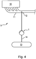
- FIG 4 shows a device 9 for exhaust gas treatment according to the present invention.
- Pump 1 off Figure 1 is used in this device to convey a urea-based aqueous solution, which is injected via a nozzle 12 as a catalyst into the exhaust line 11 of an internal combustion engine 10, for example a large diesel engine.
- the aqueous solution is conveyed from a corresponding tank 13 to the nozzle 12 via a line 14 in which the pump 1 is located.
Landscapes
- Engineering & Computer Science (AREA)
- Mechanical Engineering (AREA)
- General Engineering & Computer Science (AREA)
- Chemical & Material Sciences (AREA)
- Power Engineering (AREA)
- Chemical Kinetics & Catalysis (AREA)
- Computer Hardware Design (AREA)
- Health & Medical Sciences (AREA)
- Toxicology (AREA)
- Combustion & Propulsion (AREA)
- Control Of Positive-Displacement Pumps (AREA)
Description
- Die vorliegende Erfindung betrifft ein Verfahren zur Überwachung eines zum Antrieb einer Pumpe dienenden Elektromotors nach dem Oberbegriff des unabhängigen Anspruchs 1.
- Aus dem Stand der Technik sind zahlreiche Systeme bekannt, bei welchen ein Fluid, insbesondere ein inkompressibles Medium, mittels einer elektromotorisch betriebenen Pumpe gefördert und gegebenenfalls über entsprechende Düsen oder dergleichen in ein bestimmtes Volumen eingespritzt oder eingesprüht wird. Man denke beispielsweise an Systeme zur Kraftstoffeinspritzung. Selbst wenn der Druck im Förderkreislauf im Mittel annähernd gleichbleibt oder gleichbleiben soll, kann es bei einigen dieser Systeme aufgrund verschiedenster Einflüsse zu mehr oder minder hochfrequenten Druckschwankungen kommen. Diese können beispielsweise durch die Bauart der Pumpe selbst bedingt sein. So kommt es beispielsweise im Förderkreislauf von Membranpumpen zu relativ hohen Druckschwankungen, obwohl der mittlere Druck im Förderkreislauf annähernd konstant bleibt. Dennoch müssen Druckänderungen, die sich nicht auf die unvermeidbaren periodisch wiederkehrenden Druckschwankungen des Pumpenmechanismus zurückführen lassen, zuverlässig erkannt werden, damit die Regelung des Pumpenantriebs auf eventuell im Förderkreislauf auftretende Störungen reagieren und gegebenenfalls die Drehzahl der Pumpe nachregeln kann.
- Um den Druck im Förderkreislauf zu ermitteln, sind bei bestehenden Systemen nach dem Stand der Technik üblicherweise ein oder sogar mehrere Drucksensoren vorgesehen, deren Signale von der Steuer- und Regeleinheit des Pumpenantriebs ausgewertet werden. Darüber hinaus ist zumeist ein Druckbegrenzungsventil vorgesehen, das geöffnet wird, wenn im Förderkreislauf beispielsweise ein Problem auftritt, das zur vollständigen Blockade des Förderkreislaufs führt. Auf diese Weise wird eine Beschädigung des Pumpenantriebs vermieden, wenn dieser trotz Auftreten der Störung weiterläuft. Insbesondere wird dadurch verhindert, dass der zum Antrieb der Pumpe dienende Elektromotor und/oder Bauelemente des Förderkreislaufs nachhaltig Schaden nehmen..
- Ein Beispiel für ein derartiges System, bei dem es grundsätzlich zu Druckschwankungen im Förderkreislauf kommt, ist eine Zuführeinrichtung zur Abgasnachbehandlung von Verbrennungskraftmaschinen, insbesondere von großen Dieselmotoren. In diesem Bereich hat sich über die letzten Jahren eine Technik durchgesetzt, bei der eine Ammoniak- bzw. harnstoffbasierte Lösung in den Abgasstrang des Verbrennungskraftmotors eingespritzt wird, um den Gesamtausstoß von Stickoxiden zu vermindern. Die Lösung wirkt als Katalysator und bewirkt, dass die Stickoxide in Stickstoff und Wasserdampf aufgespalten werden. Eine derartige Zuführeinrichtung zur Abgasnachbehandlung ist beispielsweise aus
DE 102009035940 A1 bekannt. Auch bei dieser Zuführeinrichtung wird der Druck im Förderkreislauf durch einen Drucksensor ermittelt und durch den Pumpenantrieb selbst sowie durch ein Druckbegrenzungsventil geregelt. Drucksensor und Druckbegrenzungsventil stellen zusätzliche Kosten und vor allen Dingen zusätzliche mögliche Fehlerquellen dar. - Elektromotoren, die zum Antrieb von Pumpen verwendet werden, sind zumeist als elektrisch kommutierte Elektromotoren ausgeführt. Sie werden durch wechselweises Beschalten ihrer Wicklungen derart angesteuert, dass sich ein rotierendes magnetisches Feld ergibt, welches ein mechanisches Drehmoment erzeugt, das auf den Rotor des Elektromotors wirkt. Zur Erzeugung des rotierenden magnetischen Feldes umfasst der Stator mindestens zwei, häufig sogar drei Wicklungen, die in Bezug auf die Rotorachse in Umfangsrichtung zueinander versetzt angeordnet sind und die verschiedenen Phasen des Elektromotors bilden. Das wechselweise Beschalten der Wicklungen übernimmt ein Umrichter, der in aller Regel von einer Gleichspannungsquelle gespeist wird. Um die Wicklungen unterschiedlich stark mit Strom beaufschlagen zu können, arbeitet der Umrichter nach dem Prinzip der Pulsweitenmodulation. Die Steuerung des Elektromotors übernimmt eine Steuer- und Regeleinheit, der gewisse Parameter als Eingangsgrößen zugeführt werden. So wird der Steuer- und Regeleinheit beispielsweise die gewünschte Motordrehzahl als Eingangsgröße vorgegeben. Um eine Überhitzung der Statorwicklungen, welche zu einer Zerstörung des Elektromotors führen kann, zu vermeiden, werden üblicherweise die in den einzelnen Wicklungen auftretenden Wicklungsströme erfasst, so dass diese in die Regelung des Elektromotors Eingang finden können. Über die Wicklungsströme kann auch das Drehmoment des Elektromotors eingestellt werden.
- Ein Verfahren zu Regelung eines mehrphasigen elektronisch kommutierten Elektromotors ist beispielsweise in
DE 102005028344 A1 beschrieben. Bei diesem Verfahren wird der addierte Wicklungsstrom im Fußpunkt des sternförmig geschalteten Elektromotors gemessen. Der momentane Stromspitzenwert dieses addierten Wicklungsstroms wird der Steuerungs- und Regeleinheit als Regelgröße zugeführt. - Ein Verfahren zur Überwachung eines zum Antrieb einer Pumpe dienenden Elektromotors ist beispielsweise aus
WO 2012/053954 A1 bekannt. Bei diesem Verfahren werden Werte eines im Elektromotor auftretenden Stroms innerhalb eines zeitlichen Intervalls gemessen. Der Strom unterliegt innerhalb dieses zeitlichen Intervalls, insbesondere aufgrund von Druckschwankungen im Förderkreislauf der Pumpe, die sich auf das Drehmoment des Elektromotors auswirken, gewissen Schwankungen. Um einen Fehler im System zu erkennen, werden die innerhalb des zeitlichen Intervalls auftretenden lokalen Maxima des Stromverlaufs mit einem Grenzwert verglichen. Ein Fehler wird erkannt, wenn alle lokalen Maxima des Stromverlaufs unterhalb des Grenzwertes liegen. Diese Art der Fehlererkennung erlaubt es, festzustellen, ob beispielsweise die Anschlussverdrahtung der Motorwicklungen defekt bzw. unterbrochen ist. Anstatt alle lokalen Maxima des Stromverlaufs innerhalb des zeitlichen Intervalls mit dem Grenzwert zu vergleichen, kann aus den Stromwerten der lokalen Maxima auch ein Mittelwert gebildet werden, der anschließend mit dem Grenzwert verglichen wird. - Ein Verfahren gemäß dem Oberbegriff des unabhängigen Anspruchs 1 ist beispielsweise aus
US 6,599,095 B1 und ausUS 2008/0092750 A1 bekannt. - Aufgabe der vorliegenden Erfindung ist es, ein Verfahren anzugeben, das eine besonders einfache und kostengünstige Steuerung und Regelung eines Elektromotors erlaubt, welcher zum Antrieb einer Pumpe dient, in deren Förderkreislauf periodisch wiederkehrende Druckschwankungen auftreten.
- Die Aufgabe wird gelöst durch die Merkmale des unabhängigen Anspruchs 1. Demnach liegt bei einem Verfahren gemäß dem Oberbegriff des unabhängigen Anspruchs 1 dann eine erfindungsgemäße Lösung der Aufgabe vor, wenn das zeitliche Intervall (T) größer ist als eine Periodendauer (P), die sich aufgrund von systembedingten periodisch wiederkehrenden Druckschwankungen im Förderkreislauf der Pumpe (1) ergibt.
- Im Gegensatz zu dem aus
WO 2012053954 A1 bekannten Verfahren wird gemäß der vorliegenden Erfindung somit kein Mittelwert der lokalen Maxima des Stromverlaufs innerhalb des zeitlichen Intervalls ermittelt, sondern der tatsächliche Mittelwert des Stromverlaufs. Die Erfindung macht sich zunutze, dass der Wicklungsstrom direkt abhängig ist vom Drehmoment des Elektromotors, welches wiederum von dem Druck abhängt, der im Förderkreislauf der Pumpe herrscht. Durch das erfindungsgemäße Verfahren wird somit die Überwachung des Drucks im Förderkreislauf in die Motorsteuerung integriert. Lokale Maxima des Drucks, die auf die pumpenspezifischen, periodisch wiederkehrenden Druckschwankungen zurückzuführen sind, erzeugen lokale Maxima des Wicklungsstroms. Die Ermittlung der lokalen Maxima des Wicklungsstroms kann daher keinen Aufschluss darüber geben, ob im Förderkreislauf ein Überdruck herrscht, der eventuell eine Nachregelung des Elektromotors erfordert. Erfindungsgemäß wird daher der Mittelwert des Stromverlaufs innerhalb des zeitlichen Intervalls ermittelt. Dieser hängt von dem mittleren Druck im Förderkreislauf ab und steigt somit an, wenn auch der Druck im Förderkreislauf ansteigt. Auf diese Weise ist es daher möglich, den Verlauf des mittleren Drucks im Förderkreislauf ohne einen extra zu diesem Zweck vorgesehenen Drucksensor zu erfassen und der Motorregelung als Eingangsparameter zuzuführen. Die Erfindung ermöglicht somit unter anderem, dass der mittlere Druck im Förderkreislauf der Pumpe allein auf Basis des Wicklungsstroms konstant gehalten bzw. auf einen bestimmten Wert geregelt werden kann. - Das zeitliche Intervall, innerhalb dessen die Stromwerte des Wicklungsstroms gemessen werden, muss so bemessen sein, dass die systembedingten, periodisch wiederkehrenden Schwankungen des Drucks zuverlässig gemittelt werden können. Es ist daher von Vorteil, wenn das zeitliche Intervall so bemessen ist, dass innerhalb des zeitlichen Intervalls nicht nur ein lokales Maximum, sondern mehrere lokale Maxima des Wicklungsstroms auftreten. So kann vorzugsweise vorgesehen sein, dass zumindest fünf lokale Maxima des Wicklungsstroms in das zeitliche Intervall fallen. Ferner wandert das zeitliche Intervall zur Bestimmung des Mittelwerts fortlaufend mit. Beispielsweise kann ein erster Mittelwert aus den gemessenen Stromwerten in den konkret aufeinander folgenden Zeitpunkten 1, 2, 3, 4, 5, 6, 7, 8, 9, 10 ermittelt werden, wobei ein darauffolgender zweiter Mittelwert aus den gemessenen Stromwerten in den konkret aufeinanderfolgenden Zeitpunkten 2, 3, 4, 5, 6, 7, 8, 9, 10, 11 ermittelt wird. Weiter ist es von Vorteil, wenn die Abtastrate zur Messung der Stromwerte wesentlich über der Frequenz der systembedingten periodisch wiederkehrenden Druckschwankungen im Förderkreislauf liegt. Nur so ist eine zuverlässige Ermittlung des Mittelwerts des Wicklungsstroms gewährleistet. Vorzugsweise liegt die Frequenz der Abtastung um zumindest eine Größenordnung über der Frequenz der systembedingt periodisch wiederkehrenden Druckschwankungen.
- Vorteilhafte Ausgestaltungen der vorliegenden Erfindung sind Gegenstand der Unteransprüche.
- In einer besonders bevorzugten Ausführungsform der vorliegenden Erfindung wird ein von der Motorregelung vorgegebener maximal zulässiger Wert für den Motorspeisungsstrom herabgesetzt, falls der Mittelwert der gemessenen Stromstärke größer ist als der vorgegebene Referenzwert. Der Referenzwert legt somit quasi den zulässigen Druck im Förderkreislauf der Pumpe fest. Steigt dieser an, beispielsweise aufgrund einer Störung im Förderkreislauf, so wird der maximal zulässige Wert für den Motorspeisungsstrom herabgesetzt, um den Druck wieder auf den Ausgangswert zurück zu regeln und zu verhindern, dass der Elektromotor oder der Förderkreislauf aufgrund der steigenden Belastung Schaden nehmen. Die vorliegende Erfindung hat dabei den Vorteil, dass zur Begrenzung des Drucks kein zusätzlich vorgesehenes Überdruckventil erforderlich ist.
- In einer vorteilhaften Ausführungsform wird der Motorspeisungsstrom durch eine Kaskaden-Regelung mit einem schnellen, unterlagerten Regelkreis auf den maximal zulässigen Wert begrenzt. Dabei werden die gemessenen Stromwerte ohne Mittelwertbildung direkt über einen schnellen, in Hardware ausgeführten Komparator mit dem Motorspeisungsstrom verglichen. Sollten die gemessenen Stromwerte über dem maximal zulässigen Motorspeisungsstrom liegen, so wird das Tastverhältnis der Pulsweitenmodulation des Umrichters verändert.
- Eine besonders einfache Regelung ergibt sich, wenn der maximal zulässige Wert für den Motorspeisungsstrom um die Differenz zwischen Mittelwert und Referenzwert herabgesetzt wird. Um eine unruhige Regelung zu vermeiden, ist diese Differenz auf eine vorgegebene Maximaldifferenz begrenzt. Die Differenzen werden mittels eines integrierenden Reglers aufintegriert und solange von dem maximal zulässigen Wert für den Motorspeisungsstrom abgezogen, bis der resultierende Druck im System gesunken ist und der Mittelwert des Wicklungsstroms dadurch wieder unter den Referenzwert fällt. Für die Reduzierung des maximal zulässigen Werts des Motorspeisungsstroms kann ebenfalls eine vorgegebene Maximaldifferenz vorgesehen sein.
- In einer weiteren bevorzugten Ausführungsform der vorliegenden Erfindung wird der maximal zulässige Wert für den Motorspeisungsstrom maximal auf die Hälfte des Referenzwertes reduziert. Sofern im Förderkreislauf der Pumpe ein Fehler vorliegt und der Druck deshalb nicht absinken kann, wird somit solange nachgeregelt, bis der Motorspeisungsstrom nicht mehr ausreicht, um den Motor anzutreiben, so dass der Motor stehenbleibt. Dadurch, dass der maximal zulässige Wert für den Motorspeisungsstrom nur auf die Hälfte des Referenzwertes reduziert wird, liegt an der Pumpe jedoch weiterhin ein Drehmoment an, was dazu führt, dass Elektromotor und Pumpe wieder anlaufen, wenn der Fehler im Förderkreislauf behoben ist und der Druck wieder sinkt. Bei einem sensorlos kommutierten Elektromotor, welcher nicht automatisch anlaufen kann, kann alternativ nach einem Stillstand von vorgegebener Dauer der Motorspeisungsstrom wieder derart erhöht werden, so dass der Elektromotor bei einem Normaldruck im Förderkreislauf wieder anlaufen kann.
- In einer weiteren bevorzugten Ausführungsform der vorliegenden Erfindung wird der maximal zulässige Wert für den Motorspeisungsstrom wieder erhöht, sobald der Mittelwert der gemessenen Stromwerte unter den Referenzwert fällt. So werden nach Behebung des Fehlers die ursprünglichen Strömungs- und Druckverhältnisse im Förderkreislauf wiederhergestellt.
- In einer weiteren bevorzugten Ausführungsform der vorliegenden Erfindung ist der Elektromotor mehrphasig ausgeführt, wobei die Stromwerte im Fußpunkt des Umrichters gemessen werden. Dies gewährleistet eine besonders einfache, kostengünstige und vollständige Berücksichtigung sämtlicher Wicklungsströme. Es ist lediglich ein Stromsensor im Fußpunkt des Umrichters erforderlich.
- In einer weiteren bevorzugten Ausführungsform der vorliegenden Erfindung werden die Stromwerte innerhalb des zeitlichen Intervalls mit einer Abtastrate gemessen, deren Frequenz um eine Größenordnung über der Frequenz der systembedingten Druckschwankungen im Förderkreislauf der Pumpe liegt. Auch dies erhöht die Genauigkeit der Ermittlung des Mittelwerts.
- In einer weiteren bevorzugten Ausführungsform der vorliegenden Erfindung wird der Mittelwert aus einer Anzahl von Stromwerten ermittelt, die einer n-ten Potenz von 2 entspricht. Dabei sind die Messzeitpunkte idealerweise zwischen zwei lokalen Maxima des Stromverlaufs verteilt.
- Die vorliegende Erfindung stellt ferner einen maschinenlesbaren Datenträger bereit, auf dem ein Programm gespeichert ist, das eine Befehlsfolge enthält, bei deren Ausführung durch einen Prozessor das erfindungsgemäße Verfahren ausgeführt wird. Ferner stellt die Erfindung auch eine Motorregelung für einen Elektromotor zur Ausführung des erfindungsgemäßen Verfahrens bereit.
- Die Erfindung bezieht sich ferner auch auf einen Elektromotor zum Antrieb einer Pumpe, wobei der Elektromotor über eine Motorregelung zur Ausführung des erfindungsgemäßen Verfahrens verfügt. Vorzugsweise ist der Elektromotor als elektronisch kommutierter Elektromotor ausgeführt. Weiter vorzugsweise handelt es sich um einen Außenläufermotor. Alternativ kann selbstverständlich auch ein bürstenbehafteter Gleichstromelektromotor mit einer Rotorwicklung verwendet werden. Der Elektromotor eignet sich vorzugsweise zum Antrieb einer Membranpumpe. Jedoch können auch andere Pumpenmechanismen, die systembedingt periodisch wiederkehrende Druckschwankungen hervorrufen, mit dem Elektromotor betrieben werden.
- Die Erfindung eignet sich ganz besonders für eine Vorrichtung zur Abgasnachbehandlung, bei welcher eine Flüssigkeit durch die Pumpe unter Druck gesetzt und über zumindest eine Auslassvorrichtung in den Abgasstrang einer Verbrennungskraftmaschine eingespritzt oder eingesprüht wird. Bei der Flüssigkeit kann es sich beispielsweise um eine Harnstoff-Wasser-Lösung handeln.
- Ein Ausführungsbeispiel der vorliegenden Erfindung wird im Folgenden anhand von Zeichnungen näher erläutert. Es zeigen:
- Figur 1
- eine schematische Schaltungsanordnung zur Überwachung und Regelung eines zum Antrieb einer Membranpumpe dienenden Elektromotors,
- Figur 2
- einen beispielhaften Verlauf des Wicklungsstroms im Elektromotor,
- Figur 3
- ein Ablaufschema des erfindungsgemäßen Verfahrens nach einer bevorzugten Ausführungsform, und
- Figur 4
- eine Vorrichtung zur Abgasnachbehandlung gemäß der vorliegenden Erfindung.
- Für die folgenden Ausführungen gilt, dass gleiche Teile durch gleiche Bezugszeichen bezeichnet werden. Sofern in einer Zeichnung Bezugszeichen enthalten sind, auf die in der zugehörigen Figurenbeschreibung nicht näher eingegangen wird, so wird auf vorangehende oder nachfolgende Figurenbeschreibungen Bezug genommen.
-
Figur 1 zeigt eine schematische Schaltungsanordnung zur Überwachung und Regelung eines zum Antrieb einer Membranpumpe 1 dienenden Elektromotors 2. Der Elektromotor ist als elektronisch kommutierter Außenläufermotor ausgeführt. Er verfügt über drei Statorwicklungen, die in Bezug auf die Rotorachse des Elektromotors in Umfangsrichtung versetzt zueinander angeordnet sind. Die Wicklungsanschlüsse der drei Statorwicklungen sind in der Darstellung mit den Bezugszeichen 5.1, 5.2 und 5.3 bezeichnet. Als Stromversorgung ist eine Gleichspannungsquelle 15 vorgesehen, die einen Umrichter 4 speist, welcher wiederum die wechselweise Beschaltung der drei Statorwicklungen übernimmt. Die Wicklungsströme der drei Statorwicklungen fließen gemeinsam über den Fußpunkt 6 des Umrichters 4 ab. Der resultierende Gesamtwicklungsstrom wird im Fußpunkt 6 mittels eines Stromsensors 16 gemessen. Prinzipiell kann der Strom auch an einer anderen als der eingezeichneten Stelle gemessen werden. Beispielsweise ist es möglich, den Strom erst nach dem Umrichter zu messen. Auch besteht die Möglichkeit, den Wicklungsstrom einer oder mehrerer Statorwicklungen direkt in der jeweiligen Wicklung zu erfassen. Das Ausgangssignal des Stromsensors 16 wird der Motorregelung 3 zugeführt und dort verarbeitet. Die Motorregelung umfasst hierzu einen Prozessor 8, der ein Programm ausführt, das auf einem ebenfalls der Motorregelung zugeordneten, maschinenlesbaren Datenträger 7 abgespeichert ist. Bei dem Datenträger kann es sich beispielsweise um einen fest installierten oder aber auch um einen entfernbaren Datenspeicher handeln. -
Figur 2 zeigt einen beispielhaften Verlauf des im Fußpunkt 6 gemessenen resultierenden Gesamtwicklungsstroms.. Aufgetragen ist der Strom I in Ampere über der Zeit t in Millisekunden. Deutlich zu erkennen ist ein periodisch schwankender Verlauf des Wicklungsstroms, wobei der Abstand zwischen zwei lokalen Maxima der Periodendauer PP entspricht, die sich aufgrund der systembedingten periodisch wiederkehrenden Druckschwankungen im Förderkreislauf der Membranpumpe 1 ergibt. Die drei größeren in der Darstellung gezeigten Anstiege des Stromverlaufs entsprechen jeweils einem Pumpenhub der Membranpumpe, die drei kleineren Anstiege dazwischen resultieren aus dem Nachhub der Pumpe. Erfindungsgemäß wird ein momentaner Mittelwert des Wicklungsstroms ermittelt. Hierzu werden innerhalb eines zeitlichen Intervalls T mehrere diskrete Stromwerte gemessen und anschließend ein Mittelwert aus den gemessenen Stromwerten ermittelt. Das zeitliche Intervall T ist vorzugsweise größer als die Periodendauer PP. Für eine möglichst genaue Ermittlung des Mittelwerts empfiehlt es sich, wenn die Abtastrate um mindestens eine Größenordnung größer ist als die Frequenz der wiederkehrenden periodischen Schwingungen. Der ermittelte Mittelwert des Wicklungsstroms wird sodann von der Motorregelung 3 als Eingangsparameter verarbeitet. Es wird darauf hingewiesen, dass die Ermittlung des Mittelwerts sowohl in der Motorregelung 3 selbst als auch in einer separaten Schaltung erfolgen kann. Im dargestellten Beispiel liegt der zu Beginn des Stromverlaufs ermittelte Mittelwert über einem vorbestimmten Grenzwert. Der maximal zulässige Motorspeisungsstrom wird daher schrittweise zurückgeregelt, was anhand des Rückgangs der lokalen Maxima des Stromverlaufs deutlich wird und nachfolgend näher erläutert werden soll. -
Figur 3 zeigt den Ablauf des erfindungsgemäßen Verfahrens nach einer bevorzugten Ausführungsform. Es wird angenommen, dass der mittlere Druck im Förderkreislauf der Pumpe eine Änderung erfährt. Die Änderung des mittleren Drucks im Förderkreislauf bewirkt eine Änderung des benötigten Motordrehmoments, die wiederum mit einer Änderung des Wicklungsstroms einhergeht. Durch die Messung diskreter Stromwerte innerhalb des zeitlichen Intervalls T kann der momentane Mittelwert Imittel des Wicklungsstroms ermittelt werden. Dieser wird in der Motorregelung 3 mit einem vorgegebenen Referenzwert IReferenz verglichen. Der vorgegebene Referenzwert stellt einen Grenzstromwert dar. Solange der Mittelwert des Wicklungsstroms dem Grenzwert entspricht oder bei der gewünschten Drehzahl des Elektromotors sogar kleiner ist als der Referenzwert, wird der Elektromotor weiterhin unverändert bestromt. Steigt der Mittelwert jedoch über den Referenzwert, so wird der maximal zulässige Wert für den Motorspeisungsstrom herabgesetzt. Denn der Anstieg des Mittelwerts des Wicklungsstroms geht einher mit einer unerwünschten Erhöhung des mittleren Drucks im Förderkreislauf der Pumpe. Der Referenzwert IReferenz wird daher so festgelegt, dass sich im Förderkreislauf ein gewünschter Druck einstellt bzw. der mittlere Druck nicht über den gewünschten Druck ansteigt. Der maximal zulässige Wert für den Motorspeisungsstrom wird solange herunter geregelt, bis der mittlere Druck im Förderkreislauf der Pumpe wieder sinkt und der Mittelwert des Wicklungsstroms dadurch unter den Referenzwert IReferenz fällt. Kann sich der Druck nicht abbauen, beispielsweise weil die Förderleitung der Pumpe zugesetzt oder aus anderen Gründen versperrt ist, so wird solange nachgeregelt, bis der Motorspeisungsstrom des Elektromotors nicht mehr ausreicht, um den Elektromotor anzutreiben, so dass dieser stehenbleibt. Fällt der Druck jedoch wieder unter den Referenzwert IReferenz, so kann der Elektromotor wieder anlaufen, und der maximal zulässige Wert für den Motorspeisungsstrom wird schrittweise wieder auf den Ausgangswert erhöht. -
Figur 4 zeigt eine Vorrichtung 9 zur Abgasbehandlung gemäß der vorliegenden Erfindung. Die Pumpe 1 ausFigur 1 dient bei dieser Vorrichtung zur Förderung einer harnstoffbasierten wässrigen Lösung, die über eine Düse 12 als Katalysator in den Abgasstrang 11 einer Verbrennungskraftmaschine 10, beispielsweise einem großen Dieselmotor, eingespritzt wird. Die wässrige Lösung wird dazu aus einem entsprechenden Tank 13 über eine Leitung 14, in der sich die Pumpe 1 befindet, zur Düse 12 befördert.
Claims (15)
- Verfahren zur Überwachung eines zum Antrieb einer Pumpe (1) dienenden Elektromotors (2), wobei innerhalb eines zeitlichen Intervalls (T) Stromwerte gemessen werden, ein Mittelwert der gemessenen Stromwerte ermittelt, und dieser Mittelwert mit einem vorgegebenen Referenzwert verglichen wird, wobei sich das Verfahren auf die Regelung des Elektromotors (2) erstreckt, wobei die gemessenen Stromwerte den Verlauf des Wicklungsstroms des Elektromotors (2) wiedergeben und unabhängig davon, ob sie einem momentanen Maximum des Stromverlaufs zuzuordnen sind, in die Ermittlung des Mittelwerts Eingang finden, und wobei der Mittelwert als Eingangsparameter von der Motorregelung (3) berücksichtigt wird, dadurch gekennzeichnet, dass das zeitliche Intervall (T) größer ist als eine Periodendauer (P), die sich aufgrund von systembedingten periodisch wiederkehrenden Druckschwankungen im Förderkreislauf der Pumpe (1) ergibt.
- Verfahren nach Anspruch 1, dadurch gekennzeichnet, dass ein von der Motorregelung (3) vorgegebener maximal zulässiger Wert für den Motorspeisungsstrom herabgesetzt wird, falls der Mittelwert der gemessenen Stromwerte größer ist als der vorgegebene Referenzwert.
- Verfahren nach Anspruch 2, dadurch gekennzeichnet, dass der maximal zulässige Wert für den Motorspeisungsstrom um die Differenz zwischen Mittelwert und Referenzwerts herabgesetzt wird.
- Verfahren nach Anspruch 3, dadurch gekennzeichnet, dass die Differenzen mittels eines integrierenden Reglers aufintegriert und solange von dem maximal zulässigen Wert für den Motorspeisungsstrom abgezogen werden, bis der resultierende Druck im System gesunken ist und der Mittelwert des Wicklungsstroms dadurch wieder unter den Referenzwert fällt.
- Verfahren nach einem der Ansprüche 2 bis 4, dadurch gekennzeichnet, dass der maximal zulässige Wert für den Motorspeisungsstrom maximal auf die Hälfte des Referenzwertes reduziert wird.
- Verfahren nach einem der Ansprüche 2 bis 5, dadurch gekennzeichnet, dass der maximal zulässige Wert für den Motorspeisungsstrom wieder erhöht wird, sobald der Mittelwert der gemessenen Stromwerte unter den Referenzwert fällt.
- Verfahren nach einem der Ansprüche 1 bis 6, dadurch gekennzeichnet, dass der Elektromotor (2) mehrphasig ausgeführt ist, wobei die Stromwerte im Fußpunkt (6) des Umrichters (4) gemessen werden.
- Verfahren nach einem der Ansprüche 1 bis 7, dadurch gekennzeichnet, dass die Stromwerte innerhalb des Intervalls (T) mit einer Abtastrate gemessen werden, deren Frequenz um eine Größenordnung über der Frequenz der systembedingten Druckschwankungen im Förderkreislauf der Pumpe liegt.
- Verfahren nach einem der Ansprüche 1 bis 8, dadurch gekennzeichnet, dass der Mittelwert aus einer Anzahl von Stromwerten ermittelt wird, die einer n-ten Potenz von 2 entspricht.
- Maschinenlesbarer Datenträger (7) mit einem Programm, wobei der Datenträger (7) der Motorregelung (3) eines zum Antrieb einer Pumpe (1) dienenden Elektromotors (2) zugeordnet ist, wobei das Programm eine Befehlsfolge enthält, bei deren Ausführung durch einen Prozessor (8) ein Verfahren nach einem der Ansprüche 1 bis 9 ausgeführt wird.
- Motorregelung (3) für einen Elektromotor (2) zur Ausführung eines Verfahrens nach einem der Ansprüche 1 bis 9.
- Elektromotor (2) zum Antrieb einer Pumpe (1), dadurch gekennzeichnet, dass der Elektromotor (2) über eine Motorregelung (3) nach Anspruch 11 verfügt, wobei der Elektromotor (2) vorzugsweise als elektrisch kommutierter Elektromotor (2) ausgeführt ist.
- Pumpe (1) zur Förderung eines Fluids, dadurch gekennzeichnet, dass die Pumpe (1) einen Elektromotor (2) nach Anspruch 12 als Antrieb aufweist.
- Pumpe (1) nach Anspruch 13, dadurch gekennzeichnet, dass die Pumpe (1) als Membranpumpe ausgeführt ist.
- Vorrichtung (9) zur Abgasnachbehandlung, mit einer Pumpe (1), durch die eine Flüssigkeit unter Druck gesetzt und über zumindest eine Auslassvorrichtung (12) in den Abgasstrang (11) einer Verbrennungskraftmaschine (10) eingespritzt oder eingesprüht werden kann, dadurch gekennzeichnet, dass die Pumpe (1) nach Anspruch 13 oder 14 ausgeführt ist.
Priority Applications (3)
| Application Number | Priority Date | Filing Date | Title |
|---|---|---|---|
| EP14003133.7A EP2995816B1 (de) | 2014-09-10 | 2014-09-10 | Verfahren zur überwachung und regelung eines elektromotors zum antrieb einer pumpe |
| CN201510742409.5A CN105406780B (zh) | 2014-09-10 | 2015-09-09 | 用于电动机的方法和控制器以及相关数据载体和设备 |
| US14/849,815 US10018096B2 (en) | 2014-09-10 | 2015-09-10 | Method of and control for monitoring and controlling an electric motor for driving a pump |
Applications Claiming Priority (1)
| Application Number | Priority Date | Filing Date | Title |
|---|---|---|---|
| EP14003133.7A EP2995816B1 (de) | 2014-09-10 | 2014-09-10 | Verfahren zur überwachung und regelung eines elektromotors zum antrieb einer pumpe |
Publications (2)
| Publication Number | Publication Date |
|---|---|
| EP2995816A1 EP2995816A1 (de) | 2016-03-16 |
| EP2995816B1 true EP2995816B1 (de) | 2020-04-22 |
Family
ID=51582221
Family Applications (1)
| Application Number | Title | Priority Date | Filing Date |
|---|---|---|---|
| EP14003133.7A Active EP2995816B1 (de) | 2014-09-10 | 2014-09-10 | Verfahren zur überwachung und regelung eines elektromotors zum antrieb einer pumpe |
Country Status (3)
| Country | Link |
|---|---|
| US (1) | US10018096B2 (de) |
| EP (1) | EP2995816B1 (de) |
| CN (1) | CN105406780B (de) |
Cited By (1)
| Publication number | Priority date | Publication date | Assignee | Title |
|---|---|---|---|---|
| DE102022126376A1 (de) * | 2022-10-11 | 2024-04-11 | Prominent Gmbh | Verfahren zur sensorlosen Detektion der Hubausführung bei einer Magnetpumpe |
Families Citing this family (49)
| Publication number | Priority date | Publication date | Assignee | Title |
|---|---|---|---|---|
| BE1024040B1 (nl) * | 2016-04-08 | 2017-11-06 | Atlas Copco Airpower, N.V. | Elektrisch aangedreven mobiele compressor |
| WO2018051192A2 (en) * | 2016-09-16 | 2018-03-22 | Paul Davis | Displacement pump and control system |
| US11323051B2 (en) | 2017-01-15 | 2022-05-03 | Graco Minnesota Inc. | Paint sprayer with dynamic pulse width modulation driven motor |
| IT201700012147A1 (it) * | 2017-02-03 | 2018-08-03 | Fluid O Tech Srl | Metodo per la regolazione della pressione in un sistema di pompaggio. |
| US11624326B2 (en) | 2017-05-21 | 2023-04-11 | Bj Energy Solutions, Llc | Methods and systems for supplying fuel to gas turbine engines |
| CN110247587B (zh) * | 2018-03-07 | 2021-03-19 | 广东美的生活电器制造有限公司 | 食品料理机及其转速控制方法、装置 |
| US11560845B2 (en) | 2019-05-15 | 2023-01-24 | Bj Energy Solutions, Llc | Mobile gas turbine inlet air conditioning system and associated methods |
| US12338772B2 (en) | 2019-09-13 | 2025-06-24 | Bj Energy Solutions, Llc | Systems, assemblies, and methods to enhance intake air flow to a gas turbine engine of a hydraulic fracturing unit |
| US10815764B1 (en) | 2019-09-13 | 2020-10-27 | Bj Energy Solutions, Llc | Methods and systems for operating a fleet of pumps |
| CA3092865C (en) | 2019-09-13 | 2023-07-04 | Bj Energy Solutions, Llc | Power sources and transmission networks for auxiliary equipment onboard hydraulic fracturing units and associated methods |
| US11015536B2 (en) | 2019-09-13 | 2021-05-25 | Bj Energy Solutions, Llc | Methods and systems for supplying fuel to gas turbine engines |
| US10989180B2 (en) | 2019-09-13 | 2021-04-27 | Bj Energy Solutions, Llc | Power sources and transmission networks for auxiliary equipment onboard hydraulic fracturing units and associated methods |
| US11604113B2 (en) | 2019-09-13 | 2023-03-14 | Bj Energy Solutions, Llc | Fuel, communications, and power connection systems and related methods |
| CA3191280A1 (en) | 2019-09-13 | 2021-03-13 | Bj Energy Solutions, Llc | Methods and systems for supplying fuel to gas turbine engines |
| CA3092868A1 (en) | 2019-09-13 | 2021-03-13 | Bj Energy Solutions, Llc | Turbine engine exhaust duct system and methods for noise dampening and attenuation |
| CA3255036A1 (en) | 2019-09-13 | 2026-03-02 | Bj Energy Solutions, Llc | Systems and method for use of single mass flywheel alongside torsional vibration damper assembly for single acting reciprocating pump |
| US12065968B2 (en) | 2019-09-13 | 2024-08-20 | BJ Energy Solutions, Inc. | Systems and methods for hydraulic fracturing |
| CA3092859A1 (en) | 2019-09-13 | 2021-03-13 | Bj Energy Solutions, Llc | Fuel, communications, and power connection systems and related methods |
| US11002189B2 (en) | 2019-09-13 | 2021-05-11 | Bj Energy Solutions, Llc | Mobile gas turbine inlet air conditioning system and associated methods |
| CA3092863C (en) | 2019-09-13 | 2023-07-18 | Bj Energy Solutions, Llc | Fuel, communications, and power connection systems and related methods |
| US10895202B1 (en) | 2019-09-13 | 2021-01-19 | Bj Energy Solutions, Llc | Direct drive unit removal system and associated methods |
| EP3825787B1 (de) * | 2019-11-25 | 2022-09-14 | Maxon International AG | Verfahren zur schnellen regelung des mittelwerts einer regelgrösse, datenträger mit programm sowie motorregelung zur ausführung des verfahrens und antriebsmotor mit einer derartigen motorregelung |
| JP7397638B2 (ja) * | 2019-11-28 | 2023-12-13 | キヤノン株式会社 | モータ制御装置及び画像形成装置 |
| US11708829B2 (en) | 2020-05-12 | 2023-07-25 | Bj Energy Solutions, Llc | Cover for fluid systems and related methods |
| US10968837B1 (en) | 2020-05-14 | 2021-04-06 | Bj Energy Solutions, Llc | Systems and methods utilizing turbine compressor discharge for hydrostatic manifold purge |
| US11428165B2 (en) | 2020-05-15 | 2022-08-30 | Bj Energy Solutions, Llc | Onboard heater of auxiliary systems using exhaust gases and associated methods |
| US11208880B2 (en) | 2020-05-28 | 2021-12-28 | Bj Energy Solutions, Llc | Bi-fuel reciprocating engine to power direct drive turbine fracturing pumps onboard auxiliary systems and related methods |
| US10961908B1 (en) | 2020-06-05 | 2021-03-30 | Bj Energy Solutions, Llc | Systems and methods to enhance intake air flow to a gas turbine engine of a hydraulic fracturing unit |
| US11208953B1 (en) | 2020-06-05 | 2021-12-28 | Bj Energy Solutions, Llc | Systems and methods to enhance intake air flow to a gas turbine engine of a hydraulic fracturing unit |
| US11109508B1 (en) | 2020-06-05 | 2021-08-31 | Bj Energy Solutions, Llc | Enclosure assembly for enhanced cooling of direct drive unit and related methods |
| US11066915B1 (en) | 2020-06-09 | 2021-07-20 | Bj Energy Solutions, Llc | Methods for detection and mitigation of well screen out |
| US11111768B1 (en) | 2020-06-09 | 2021-09-07 | Bj Energy Solutions, Llc | Drive equipment and methods for mobile fracturing transportation platforms |
| US10954770B1 (en) | 2020-06-09 | 2021-03-23 | Bj Energy Solutions, Llc | Systems and methods for exchanging fracturing components of a hydraulic fracturing unit |
| US11022526B1 (en) | 2020-06-09 | 2021-06-01 | Bj Energy Solutions, Llc | Systems and methods for monitoring a condition of a fracturing component section of a hydraulic fracturing unit |
| US11028677B1 (en) | 2020-06-22 | 2021-06-08 | Bj Energy Solutions, Llc | Stage profiles for operations of hydraulic systems and associated methods |
| US11933153B2 (en) | 2020-06-22 | 2024-03-19 | Bj Energy Solutions, Llc | Systems and methods to operate hydraulic fracturing units using automatic flow rate and/or pressure control |
| US11125066B1 (en) | 2020-06-22 | 2021-09-21 | Bj Energy Solutions, Llc | Systems and methods to operate a dual-shaft gas turbine engine for hydraulic fracturing |
| US11939853B2 (en) | 2020-06-22 | 2024-03-26 | Bj Energy Solutions, Llc | Systems and methods providing a configurable staged rate increase function to operate hydraulic fracturing units |
| US11466680B2 (en) | 2020-06-23 | 2022-10-11 | Bj Energy Solutions, Llc | Systems and methods of utilization of a hydraulic fracturing unit profile to operate hydraulic fracturing units |
| US11473413B2 (en) | 2020-06-23 | 2022-10-18 | Bj Energy Solutions, Llc | Systems and methods to autonomously operate hydraulic fracturing units |
| US11220895B1 (en) | 2020-06-24 | 2022-01-11 | Bj Energy Solutions, Llc | Automated diagnostics of electronic instrumentation in a system for fracturing a well and associated methods |
| US11149533B1 (en) | 2020-06-24 | 2021-10-19 | Bj Energy Solutions, Llc | Systems to monitor, detect, and/or intervene relative to cavitation and pulsation events during a hydraulic fracturing operation |
| US11193360B1 (en) | 2020-07-17 | 2021-12-07 | Bj Energy Solutions, Llc | Methods, systems, and devices to enhance fracturing fluid delivery to subsurface formations during high-pressure fracturing operations |
| US11639654B2 (en) | 2021-05-24 | 2023-05-02 | Bj Energy Solutions, Llc | Hydraulic fracturing pumps to enhance flow of fracturing fluid into wellheads and related methods |
| US12551685B2 (en) | 2021-07-07 | 2026-02-17 | Fbr Medical, Inc. | Partially-deformable impeller and catheter blood pump incorporating same |
| CA3180024C (en) | 2021-10-25 | 2026-04-21 | Bj Energy Solutions, Llc | Systems and methods to reduce acoustic resonance or disrupt standing wave formation in a fluid manifold of a high-pressure fracturing system |
| EP4489917A1 (de) | 2022-03-09 | 2025-01-15 | Graco Minnesota Inc. | Flüssigkeitszerstäuber |
| DE102022113913A1 (de) | 2022-06-02 | 2023-12-07 | Liebherr-Aerospace Lindenberg Gmbh | Vorrichtung und Verfahren zur Zustandsüberwachung einer Elektromotorpumpe |
| DE102023111782A1 (de) | 2023-05-05 | 2024-11-07 | KSB SE & Co. KGaA | Verfahren zur Detektion von Kavitation und/oder einer Lufteinperlung bzw. Lufteinströmung innerhalb eines hydraulischen Systems |
Family Cites Families (10)
| Publication number | Priority date | Publication date | Assignee | Title |
|---|---|---|---|---|
| US4508487A (en) * | 1979-04-06 | 1985-04-02 | Cmd Enterprises, Inc. | Automatic load seeking control for a pumpjack motor |
| US4455612A (en) * | 1982-01-27 | 1984-06-19 | Iowa State University Research Foundation, Inc. | Recursive estimation in digital distance relaying system |
| WO2000066892A1 (en) * | 1999-04-28 | 2000-11-09 | Kabushiki Kaisha Yaskawa Denki | Pump-off control for pumping jack |
| FR2875962B1 (fr) * | 2004-09-30 | 2006-12-01 | Seb Sa | Procede de protection electrique d'un appareil electromenager |
| DE102005028344A1 (de) | 2005-02-05 | 2006-08-17 | Diehl Ako Stiftung & Co. Kg | Verfahren und Schaltungsanordnung zur Regelung eines mehrphasigen bürstenlosen Elektromotors |
| EP2120323B1 (de) * | 2008-05-13 | 2010-03-10 | STMicroelectronics S.r.l. | Strangstrommessungen an einer Drehstrombrücke mit einem einzigen, gemeinsamen Stromsensor im Gleichspannungszwischenkreis |
| DE102009035940C5 (de) | 2009-08-03 | 2017-04-20 | Cummins Ltd. | SCR-Abgasnachbehandlungseinrichtung |
| SE1051100A1 (sv) | 2010-10-22 | 2012-04-23 | Scania Cv Ab | Anordning och förfarande för funktionsdetektering hos en matningskonfiguration |
| JP2013143878A (ja) * | 2012-01-12 | 2013-07-22 | Panasonic Corp | インバータ制御装置 |
| DE102012024400A1 (de) * | 2012-12-13 | 2014-06-18 | Wabco Gmbh | Verdichter zur Erzeugung von Druckluft, Druckluftversorgungsanlage, pneuma-tisches System und Verfahren zum Betrieb eines Verdichters |
-
2014
- 2014-09-10 EP EP14003133.7A patent/EP2995816B1/de active Active
-
2015
- 2015-09-09 CN CN201510742409.5A patent/CN105406780B/zh active Active
- 2015-09-10 US US14/849,815 patent/US10018096B2/en active Active
Non-Patent Citations (1)
| Title |
|---|
| None * |
Cited By (2)
| Publication number | Priority date | Publication date | Assignee | Title |
|---|---|---|---|---|
| DE102022126376A1 (de) * | 2022-10-11 | 2024-04-11 | Prominent Gmbh | Verfahren zur sensorlosen Detektion der Hubausführung bei einer Magnetpumpe |
| US12529365B2 (en) | 2022-10-11 | 2026-01-20 | Prominent Gmbh | Process for sensorless detection of stroke execution in a magnetic pump |
Also Published As
| Publication number | Publication date |
|---|---|
| US10018096B2 (en) | 2018-07-10 |
| US20160072415A1 (en) | 2016-03-10 |
| EP2995816A1 (de) | 2016-03-16 |
| CN105406780B (zh) | 2019-12-24 |
| CN105406780A (zh) | 2016-03-16 |
Similar Documents
| Publication | Publication Date | Title |
|---|---|---|
| EP2995816A1 (de) | Verfahren zur überwachung und regelung eines elektromotors zum antrieb einer pumpe | |
| EP0230009A2 (de) | Verfahren zum Regeln von Turbokompressoren zur Vermeidung des Pumpens | |
| DE102011076955B4 (de) | Verfahren zur Diagnose eines Dosiersystems und Vorrichtung zur Durchführung des Verfahrens | |
| DE102010030860A1 (de) | Verfahren zum Betreiben eines Reduktionsmitteldosiersystems für einen SCR-Katalysator | |
| DE102011078870A1 (de) | Verfahren zur Überwachung von Funktionen eines Dosiersystems | |
| WO2015022058A1 (de) | Verfahren zur injektorindividuellen diagnose einer kraftstoff-einspritzeinrichtung und brennkraftmaschine mit einer kraftstoff-einspritzeinrichtung | |
| DE102011003499A1 (de) | Verfahren zur Überwachung eines Dosiersystems insbesondere für einen SCR-Katalysator | |
| EP3792491A1 (de) | Verfahren und vorrichtung zum betreiben einer drehzahlgeregelten fluidpumpe | |
| EP2496814A1 (de) | Verfahren und vorrichtung zum überwachen eines hochdruckkraftstoffsystems | |
| EP3976963B1 (de) | Verfahren und vorrichtung zur bestimmung einer amplitude einer pumpeninduzierten fluiddruckschwankung eines fluids | |
| DE102013200540A1 (de) | Verfahren und Vorrichtung zur Erkennung eines Bewegungsbeginns von elektromechanischen Aktuatoren | |
| EP2180168A2 (de) | Verfahren und Steuervorrichtung zur Ansteuerung eines Kraftstoffinjektors | |
| EP1568874B1 (de) | Verfahren und Vorrichtung zur Steuerung des Volumenstroms in einem Kraftstoff-Einspritzsystem einer Brennkraftmaschine | |
| EP3460241B2 (de) | Verfahren zur überwachung einer magnetkolbenpumpe | |
| WO2015150049A1 (de) | Verfahren und vorrichtung zur überwachung der temperatur des spulendrahtes eines magnetventils | |
| DE102013200506A1 (de) | Verfahren und Vorrichtung zur Bestimmung eines Loslaufzeitpunkts eines elektromechanischen Aktuators | |
| DE102016102169A1 (de) | Fluidinjektor für Abgasadditive | |
| EP1863689B1 (de) | Optimierte erfassung der nachlaufspannung bei dc-motoren | |
| DE102011088703A1 (de) | Verfahren zur Messung des Stromverlaufs einer Hubkolbenpumpe | |
| WO2018077526A1 (de) | Verfahren zur realisierung erhöhter mengengenauigkeit in druckgeregelten dosiersystemen | |
| DE102017204077A1 (de) | Verfahren zum Betrieb einer Hubmagnetpumpe und Computerprogrammprodukt | |
| DE102011121629A1 (de) | Verfahren zum Steuern einer Kraftstoffeinspritzeinrichtung | |
| DE102013207867B4 (de) | Verfahren zur Diagnose eines Dosierventils und Vorrichtung zur Durchführung des Verfahrens | |
| EP2044317B1 (de) | Verfahren zur ermittlung eines fehlers in einer kraftstoffzumesseinheit eines einspritzsystems | |
| DE102014205919A1 (de) | Verfahren zum Betreiben eines elektromagnetisch betriebenen Schaltantriebs, Vorrichtung zur Durchführung des Verfahrens, Computerprogramm sowie Computerprogrammprodukt |
Legal Events
| Date | Code | Title | Description |
|---|---|---|---|
| PUAI | Public reference made under article 153(3) epc to a published international application that has entered the european phase |
Free format text: ORIGINAL CODE: 0009012 |
|
| AK | Designated contracting states |
Kind code of ref document: A1 Designated state(s): AL AT BE BG CH CY CZ DE DK EE ES FI FR GB GR HR HU IE IS IT LI LT LU LV MC MK MT NL NO PL PT RO RS SE SI SK SM TR |
|
| AX | Request for extension of the european patent |
Extension state: BA ME |
|
| RAP1 | Party data changed (applicant data changed or rights of an application transferred) |
Owner name: LAKEVIEW INNOVATION LTD. |
|
| 17P | Request for examination filed |
Effective date: 20160728 |
|
| RBV | Designated contracting states (corrected) |
Designated state(s): AL AT BE BG CH CY CZ DE DK EE ES FI FR GB GR HR HU IE IS IT LI LT LU LV MC MK MT NL NO PL PT RO RS SE SI SK SM TR |
|
| STAA | Information on the status of an ep patent application or granted ep patent |
Free format text: STATUS: EXAMINATION IS IN PROGRESS |
|
| 17Q | First examination report despatched |
Effective date: 20190124 |
|
| GRAP | Despatch of communication of intention to grant a patent |
Free format text: ORIGINAL CODE: EPIDOSNIGR1 |
|
| STAA | Information on the status of an ep patent application or granted ep patent |
Free format text: STATUS: GRANT OF PATENT IS INTENDED |
|
| INTG | Intention to grant announced |
Effective date: 20191106 |
|
| GRAS | Grant fee paid |
Free format text: ORIGINAL CODE: EPIDOSNIGR3 |
|
| GRAA | (expected) grant |
Free format text: ORIGINAL CODE: 0009210 |
|
| STAA | Information on the status of an ep patent application or granted ep patent |
Free format text: STATUS: THE PATENT HAS BEEN GRANTED |
|
| RAP1 | Party data changed (applicant data changed or rights of an application transferred) |
Owner name: MAXON INTERNATIONAL AG |
|
| AK | Designated contracting states |
Kind code of ref document: B1 Designated state(s): AL AT BE BG CH CY CZ DE DK EE ES FI FR GB GR HR HU IE IS IT LI LT LU LV MC MK MT NL NO PL PT RO RS SE SI SK SM TR |
|
| REG | Reference to a national code |
Ref country code: GB Ref legal event code: FG4D Free format text: NOT ENGLISH |
|
| REG | Reference to a national code |
Ref country code: CH Ref legal event code: EP Ref country code: CH Ref legal event code: NV Representative=s name: BOVARD AG PATENT- UND MARKENANWAELTE, CH |
|
| REG | Reference to a national code |
Ref country code: IE Ref legal event code: FG4D Free format text: LANGUAGE OF EP DOCUMENT: GERMAN |
|
| REG | Reference to a national code |
Ref country code: DE Ref legal event code: R096 Ref document number: 502014014018 Country of ref document: DE |
|
| REG | Reference to a national code |
Ref country code: AT Ref legal event code: REF Ref document number: 1260453 Country of ref document: AT Kind code of ref document: T Effective date: 20200515 |
|
| REG | Reference to a national code |
Ref country code: SE Ref legal event code: TRGR |
|
| REG | Reference to a national code |
Ref country code: NL Ref legal event code: FP |
|
| REG | Reference to a national code |
Ref country code: LT Ref legal event code: MG4D |
|
| PG25 | Lapsed in a contracting state [announced via postgrant information from national office to epo] |
Ref country code: GR Free format text: LAPSE BECAUSE OF FAILURE TO SUBMIT A TRANSLATION OF THE DESCRIPTION OR TO PAY THE FEE WITHIN THE PRESCRIBED TIME-LIMIT Effective date: 20200723 Ref country code: FI Free format text: LAPSE BECAUSE OF FAILURE TO SUBMIT A TRANSLATION OF THE DESCRIPTION OR TO PAY THE FEE WITHIN THE PRESCRIBED TIME-LIMIT Effective date: 20200422 Ref country code: LT Free format text: LAPSE BECAUSE OF FAILURE TO SUBMIT A TRANSLATION OF THE DESCRIPTION OR TO PAY THE FEE WITHIN THE PRESCRIBED TIME-LIMIT Effective date: 20200422 Ref country code: PT Free format text: LAPSE BECAUSE OF FAILURE TO SUBMIT A TRANSLATION OF THE DESCRIPTION OR TO PAY THE FEE WITHIN THE PRESCRIBED TIME-LIMIT Effective date: 20200824 Ref country code: IS Free format text: LAPSE BECAUSE OF FAILURE TO SUBMIT A TRANSLATION OF THE DESCRIPTION OR TO PAY THE FEE WITHIN THE PRESCRIBED TIME-LIMIT Effective date: 20200822 Ref country code: NO Free format text: LAPSE BECAUSE OF FAILURE TO SUBMIT A TRANSLATION OF THE DESCRIPTION OR TO PAY THE FEE WITHIN THE PRESCRIBED TIME-LIMIT Effective date: 20200722 |
|
| PG25 | Lapsed in a contracting state [announced via postgrant information from national office to epo] |
Ref country code: HR Free format text: LAPSE BECAUSE OF FAILURE TO SUBMIT A TRANSLATION OF THE DESCRIPTION OR TO PAY THE FEE WITHIN THE PRESCRIBED TIME-LIMIT Effective date: 20200422 Ref country code: RS Free format text: LAPSE BECAUSE OF FAILURE TO SUBMIT A TRANSLATION OF THE DESCRIPTION OR TO PAY THE FEE WITHIN THE PRESCRIBED TIME-LIMIT Effective date: 20200422 Ref country code: BG Free format text: LAPSE BECAUSE OF FAILURE TO SUBMIT A TRANSLATION OF THE DESCRIPTION OR TO PAY THE FEE WITHIN THE PRESCRIBED TIME-LIMIT Effective date: 20200722 Ref country code: LV Free format text: LAPSE BECAUSE OF FAILURE TO SUBMIT A TRANSLATION OF THE DESCRIPTION OR TO PAY THE FEE WITHIN THE PRESCRIBED TIME-LIMIT Effective date: 20200422 |
|
| PG25 | Lapsed in a contracting state [announced via postgrant information from national office to epo] |
Ref country code: AL Free format text: LAPSE BECAUSE OF FAILURE TO SUBMIT A TRANSLATION OF THE DESCRIPTION OR TO PAY THE FEE WITHIN THE PRESCRIBED TIME-LIMIT Effective date: 20200422 |
|
| REG | Reference to a national code |
Ref country code: DE Ref legal event code: R097 Ref document number: 502014014018 Country of ref document: DE |
|
| PG25 | Lapsed in a contracting state [announced via postgrant information from national office to epo] |
Ref country code: ES Free format text: LAPSE BECAUSE OF FAILURE TO SUBMIT A TRANSLATION OF THE DESCRIPTION OR TO PAY THE FEE WITHIN THE PRESCRIBED TIME-LIMIT Effective date: 20200422 Ref country code: CZ Free format text: LAPSE BECAUSE OF FAILURE TO SUBMIT A TRANSLATION OF THE DESCRIPTION OR TO PAY THE FEE WITHIN THE PRESCRIBED TIME-LIMIT Effective date: 20200422 Ref country code: RO Free format text: LAPSE BECAUSE OF FAILURE TO SUBMIT A TRANSLATION OF THE DESCRIPTION OR TO PAY THE FEE WITHIN THE PRESCRIBED TIME-LIMIT Effective date: 20200422 Ref country code: SM Free format text: LAPSE BECAUSE OF FAILURE TO SUBMIT A TRANSLATION OF THE DESCRIPTION OR TO PAY THE FEE WITHIN THE PRESCRIBED TIME-LIMIT Effective date: 20200422 Ref country code: EE Free format text: LAPSE BECAUSE OF FAILURE TO SUBMIT A TRANSLATION OF THE DESCRIPTION OR TO PAY THE FEE WITHIN THE PRESCRIBED TIME-LIMIT Effective date: 20200422 Ref country code: DK Free format text: LAPSE BECAUSE OF FAILURE TO SUBMIT A TRANSLATION OF THE DESCRIPTION OR TO PAY THE FEE WITHIN THE PRESCRIBED TIME-LIMIT Effective date: 20200422 |
|
| PG25 | Lapsed in a contracting state [announced via postgrant information from national office to epo] |
Ref country code: SK Free format text: LAPSE BECAUSE OF FAILURE TO SUBMIT A TRANSLATION OF THE DESCRIPTION OR TO PAY THE FEE WITHIN THE PRESCRIBED TIME-LIMIT Effective date: 20200422 Ref country code: PL Free format text: LAPSE BECAUSE OF FAILURE TO SUBMIT A TRANSLATION OF THE DESCRIPTION OR TO PAY THE FEE WITHIN THE PRESCRIBED TIME-LIMIT Effective date: 20200422 |
|
| PLBE | No opposition filed within time limit |
Free format text: ORIGINAL CODE: 0009261 |
|
| STAA | Information on the status of an ep patent application or granted ep patent |
Free format text: STATUS: NO OPPOSITION FILED WITHIN TIME LIMIT |
|
| 26N | No opposition filed |
Effective date: 20210125 |
|
| PG25 | Lapsed in a contracting state [announced via postgrant information from national office to epo] |
Ref country code: MC Free format text: LAPSE BECAUSE OF FAILURE TO SUBMIT A TRANSLATION OF THE DESCRIPTION OR TO PAY THE FEE WITHIN THE PRESCRIBED TIME-LIMIT Effective date: 20200422 |
|
| PG25 | Lapsed in a contracting state [announced via postgrant information from national office to epo] |
Ref country code: SI Free format text: LAPSE BECAUSE OF FAILURE TO SUBMIT A TRANSLATION OF THE DESCRIPTION OR TO PAY THE FEE WITHIN THE PRESCRIBED TIME-LIMIT Effective date: 20200422 |
|
| REG | Reference to a national code |
Ref country code: BE Ref legal event code: MM Effective date: 20200930 |
|
| PG25 | Lapsed in a contracting state [announced via postgrant information from national office to epo] |
Ref country code: LU Free format text: LAPSE BECAUSE OF NON-PAYMENT OF DUE FEES Effective date: 20200910 |
|
| PG25 | Lapsed in a contracting state [announced via postgrant information from national office to epo] |
Ref country code: IE Free format text: LAPSE BECAUSE OF NON-PAYMENT OF DUE FEES Effective date: 20200910 Ref country code: BE Free format text: LAPSE BECAUSE OF NON-PAYMENT OF DUE FEES Effective date: 20200930 |
|
| PG25 | Lapsed in a contracting state [announced via postgrant information from national office to epo] |
Ref country code: TR Free format text: LAPSE BECAUSE OF FAILURE TO SUBMIT A TRANSLATION OF THE DESCRIPTION OR TO PAY THE FEE WITHIN THE PRESCRIBED TIME-LIMIT Effective date: 20200422 Ref country code: MT Free format text: LAPSE BECAUSE OF FAILURE TO SUBMIT A TRANSLATION OF THE DESCRIPTION OR TO PAY THE FEE WITHIN THE PRESCRIBED TIME-LIMIT Effective date: 20200422 Ref country code: CY Free format text: LAPSE BECAUSE OF FAILURE TO SUBMIT A TRANSLATION OF THE DESCRIPTION OR TO PAY THE FEE WITHIN THE PRESCRIBED TIME-LIMIT Effective date: 20200422 |
|
| PG25 | Lapsed in a contracting state [announced via postgrant information from national office to epo] |
Ref country code: MK Free format text: LAPSE BECAUSE OF FAILURE TO SUBMIT A TRANSLATION OF THE DESCRIPTION OR TO PAY THE FEE WITHIN THE PRESCRIBED TIME-LIMIT Effective date: 20200422 |
|
| REG | Reference to a national code |
Ref country code: CH Ref legal event code: U11 Free format text: ST27 STATUS EVENT CODE: U-0-0-U10-U11 (AS PROVIDED BY THE NATIONAL OFFICE) Effective date: 20251001 |
|
| PGFP | Annual fee paid to national office [announced via postgrant information from national office to epo] |
Ref country code: DE Payment date: 20250919 Year of fee payment: 12 |
|
| PGFP | Annual fee paid to national office [announced via postgrant information from national office to epo] |
Ref country code: NL Payment date: 20250922 Year of fee payment: 12 |
|
| PGFP | Annual fee paid to national office [announced via postgrant information from national office to epo] |
Ref country code: GB Payment date: 20250923 Year of fee payment: 12 |
|
| PGFP | Annual fee paid to national office [announced via postgrant information from national office to epo] |
Ref country code: FR Payment date: 20250924 Year of fee payment: 12 Ref country code: AT Payment date: 20250918 Year of fee payment: 12 |
|
| PGFP | Annual fee paid to national office [announced via postgrant information from national office to epo] |
Ref country code: SE Payment date: 20250922 Year of fee payment: 12 |
|
| PGFP | Annual fee paid to national office [announced via postgrant information from national office to epo] |
Ref country code: IT Payment date: 20250930 Year of fee payment: 12 |
|
| PGFP | Annual fee paid to national office [announced via postgrant information from national office to epo] |
Ref country code: CH Payment date: 20251001 Year of fee payment: 12 |