EP2995460A2 - Flüssigkeitsbehälter mit arretierungsschnittstelle für mikrofluidische anwendungen - Google Patents
Flüssigkeitsbehälter mit arretierungsschnittstelle für mikrofluidische anwendungen Download PDFInfo
- Publication number
- EP2995460A2 EP2995460A2 EP15185920.4A EP15185920A EP2995460A2 EP 2995460 A2 EP2995460 A2 EP 2995460A2 EP 15185920 A EP15185920 A EP 15185920A EP 2995460 A2 EP2995460 A2 EP 2995460A2
- Authority
- EP
- European Patent Office
- Prior art keywords
- fluid
- interior
- container
- housing
- chamber
- Prior art date
- Legal status (The legal status is an assumption and is not a legal conclusion. Google has not performed a legal analysis and makes no representation as to the accuracy of the status listed.)
- Granted
Links
- 239000012530 fluid Substances 0.000 title claims abstract description 59
- 238000002156 mixing Methods 0.000 claims abstract description 22
- 230000005484 gravity Effects 0.000 claims abstract description 6
- 238000004891 communication Methods 0.000 claims abstract description 3
- 239000000976 ink Substances 0.000 description 36
- 238000003384 imaging method Methods 0.000 description 30
- 238000013461 design Methods 0.000 description 8
- 239000000049 pigment Substances 0.000 description 7
- 238000013022 venting Methods 0.000 description 6
- 239000000203 mixture Substances 0.000 description 4
- 230000009471 action Effects 0.000 description 3
- 230000008901 benefit Effects 0.000 description 3
- 239000003086 colorant Substances 0.000 description 3
- 238000000034 method Methods 0.000 description 3
- 238000012986 modification Methods 0.000 description 3
- 230000004048 modification Effects 0.000 description 3
- 238000010276 construction Methods 0.000 description 2
- 238000007641 inkjet printing Methods 0.000 description 2
- 238000002955 isolation Methods 0.000 description 2
- 239000002245 particle Substances 0.000 description 2
- 238000007639 printing Methods 0.000 description 2
- 238000007789 sealing Methods 0.000 description 2
- 239000013049 sediment Substances 0.000 description 2
- 230000003213 activating effect Effects 0.000 description 1
- 230000001186 cumulative effect Effects 0.000 description 1
- 239000001041 dye based ink Substances 0.000 description 1
- 238000005516 engineering process Methods 0.000 description 1
- 238000009472 formulation Methods 0.000 description 1
- 239000011521 glass Substances 0.000 description 1
- 238000003780 insertion Methods 0.000 description 1
- 230000037431 insertion Effects 0.000 description 1
- 238000004519 manufacturing process Methods 0.000 description 1
- 239000000463 material Substances 0.000 description 1
- 238000010907 mechanical stirring Methods 0.000 description 1
- 230000007246 mechanism Effects 0.000 description 1
- 239000002184 metal Substances 0.000 description 1
- 239000001042 pigment based ink Substances 0.000 description 1
- 239000004033 plastic Substances 0.000 description 1
- 230000008569 process Effects 0.000 description 1
- 238000003756 stirring Methods 0.000 description 1
- 238000003860 storage Methods 0.000 description 1
- 238000003466 welding Methods 0.000 description 1
Images

Classifications
-
- B—PERFORMING OPERATIONS; TRANSPORTING
- B41—PRINTING; LINING MACHINES; TYPEWRITERS; STAMPS
- B41J—TYPEWRITERS; SELECTIVE PRINTING MECHANISMS, i.e. MECHANISMS PRINTING OTHERWISE THAN FROM A FORME; CORRECTION OF TYPOGRAPHICAL ERRORS
- B41J2/00—Typewriters or selective printing mechanisms characterised by the printing or marking process for which they are designed
- B41J2/005—Typewriters or selective printing mechanisms characterised by the printing or marking process for which they are designed characterised by bringing liquid or particles selectively into contact with a printing material
- B41J2/01—Ink jet
- B41J2/17—Ink jet characterised by ink handling
- B41J2/175—Ink supply systems ; Circuit parts therefor
- B41J2/17503—Ink cartridges
- B41J2/1752—Mounting within the printer
-
- B—PERFORMING OPERATIONS; TRANSPORTING
- B41—PRINTING; LINING MACHINES; TYPEWRITERS; STAMPS
- B41J—TYPEWRITERS; SELECTIVE PRINTING MECHANISMS, i.e. MECHANISMS PRINTING OTHERWISE THAN FROM A FORME; CORRECTION OF TYPOGRAPHICAL ERRORS
- B41J2/00—Typewriters or selective printing mechanisms characterised by the printing or marking process for which they are designed
- B41J2/005—Typewriters or selective printing mechanisms characterised by the printing or marking process for which they are designed characterised by bringing liquid or particles selectively into contact with a printing material
- B41J2/01—Ink jet
- B41J2/17—Ink jet characterised by ink handling
- B41J2/175—Ink supply systems ; Circuit parts therefor
- B41J2/17503—Ink cartridges
- B41J2/17513—Inner structure
-
- B—PERFORMING OPERATIONS; TRANSPORTING
- B41—PRINTING; LINING MACHINES; TYPEWRITERS; STAMPS
- B41J—TYPEWRITERS; SELECTIVE PRINTING MECHANISMS, i.e. MECHANISMS PRINTING OTHERWISE THAN FROM A FORME; CORRECTION OF TYPOGRAPHICAL ERRORS
- B41J2/00—Typewriters or selective printing mechanisms characterised by the printing or marking process for which they are designed
- B41J2/005—Typewriters or selective printing mechanisms characterised by the printing or marking process for which they are designed characterised by bringing liquid or particles selectively into contact with a printing material
- B41J2/01—Ink jet
- B41J2/17—Ink jet characterised by ink handling
- B41J2/175—Ink supply systems ; Circuit parts therefor
- B41J2/17503—Ink cartridges
- B41J2/17553—Outer structure
Definitions
- the present invention relates to micro-fluid applications, such as inkjet printing. More particularly, although not exclusively, it relates to supply item containers that overcome settling problems associated with pigmented ink and to interfacing the container with an imaging device.
- a permanent or semi-permanent ejection head has access to a local or remote supply of fluid.
- the fluid ejects from an ejection zone to a print media in a pattern of pixels corresponding to images being printed.
- the fluid is dye or pigment based ink.
- pigments ink is known to have layers of differing concentrations. Sediments in a container settle downward over time leaving rich concentrations near a bottom, while leaner concentrations remain near a top.
- ink drawn from the bottom of a settled container leads first to excessively densely colors and later to excessively lightly colors.
- the former can also lead to clogging of ejection head nozzles as the largest particles accumulate together in micron-sized channels having fastidious fluid flow standards. Further, it may lead to increased viscosity making fluid ejection difficult.
- a container to hold an initial or refillable volume of fluid is provided.
- Its housing defines an interior and exterior.
- the interior retains the ink and an exit port supplies it to an imaging device. Users orient the housing to deplete the ink in a direction of gravity toward a bottom surface of the interior where a mixing chamber resides.
- the chamber has inlet ports arranged to restrict to multiple different heights the entrance of the volume of ink from the interior. As ink draws into the chamber, sediments from different layers mix together. High-concentrated ink settled near a bottom of the container combines with less concentrated ink from above. Pigment settling is overcome during periods of inactivity. The design improves conventional wisdom requiring mechanical stirring and other techniques. It also limits entrainment of settled particles at the bottom of the container. It adds little cost yet provides substantial mixing of pigmented ink components. Further embodiments note chamber shapes, configuration of inlet ports, and construction of the supply item, to name a few.
- the imaging device also has a rotating latch to keep in place the supply item during use. Users activate the latch to eject the supply item after use.
- the latch mates with a notch on a top exterior surface of the supply item.
- a first face of the notch engages a front of the latch, while a second face engages a side of the latch.
- the first face is angled to allow the latch to swing into and away from contact with the notch while the second face substantially parallels a side of the latch when the latch is engaged with the first face.
- the faces of the notch each have differing angles and differing lengths. Other embodiments recite degrees of angles, container slots to hold the supply item, and consumer features, to name a few.
- the housing of the supply items notes fluid exit and air venting ports. They reside on a side of the housing that gets inserted first into the container slot of the imaging device. A space separates the ports so a biasing member can push against the housing to assist in ejecting the supply item upon users activating the latch.
- the ports are separated a maximum distance to facilitate ejection, while the exit port is situated near a bottom to minimize stranding ink. Further embodiments note port arrangements and distances.
- methods and apparatus include mixing chambers for ink containers to overcome settling problems associated with pigmented ink.
- Container features to interface latches and fluidic ports are also noted.
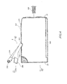
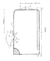
- a supply item 10 for use in an imaging device includes a structural support 12.
- the support defines an interior 14 that contains an initial or refillable supply of ink 16.
- the ink is any of a variety of aqueous inks, such as those based on dye or pigmented formulations. It also can typify varieties of color, such as cyan, magenta, yellow, black, etc. It can be used in many applications such as inkjet printing, medicinal delivery, forming circuit traces, etc.
- the volume of ink depletes downward toward a bottom surface 18 of the interior in a direction of gravity G.
- the bottom surface is generally flat or concaved upward to define a low point area or sump S from which the ink can be drawn.
- the ink flows out of the interior to the imaging device by way of an exit port 20.
- An air venting port 22 vertically aligned and above the exit port provides intake of ambient, recycled or other air to overcome backpressure that increases during imaging operations.
- the air venting port is also optimally at least 2 mm above the ink 16 in the interior when full.
- the exit and venting ports are any of a variety but typify cylindrical tubes 24 with an internal ball 26 and spring 28. They are mated with a septum needle 30 from the imaging device.
- the needle inserts into the port in the direction of the arrow A. It is pushed to overcome the bias of the spring and the ball slides backward. Upon sufficient insertion, openings 32, 34 in the port and needle are communicated so that a fluidic channel opens between the interior 14 and the needle.
- a mixing chamber resides above the sump S. It has a chamber interior 62 in fluid communication between the interior 14 and the fluid exit port 20. It communicates directly with a passageway 72 that flows to the exit port 20 for use in the imaging device. Ink is substantially mixed in the chamber before entering the passageway. The mixture yields an optimal and continual concentration of pigment.
- At least one continual wall or pluralities of wall sections define the size and shape of the mixing chamber.
- Pluralities of fluid inlet ports (F) reside in the wall(s). They are arranged to restrict the passage of a volume of fluid from the interior 14 into the chamber interior at multiple heights above the bottom surface of the interior.
- a first of the fluid inlet ports F1 is defined at an apex of the chamber. It is a topmost opening in a connecting wall defined by two inclined surfaces 63, 65 angling upward from two walls 67, 69 oriented upright from the bottom surface 18. The angle facilitates movement upward and exit at F1 of bubbles trapped in the chamber interior under the inclined surfaces.
- the angle ⁇ is any of a variety but ranges in certain embodiments from about nine to about thirteen degrees from horizontal.
- the angle is about ten to eleven degrees.
- the port F1 also directs flow incoming to the chamber in an upward direction toward an area of less rich concentration.
- the connecting wall has no inclinations and is relatively horizontal across the bottom surface between the upright walls.
- the thickness of the walls are thick enough to provide structural rigidity over the life of a container, but not so thick they consume valuable space in the container that could be otherwise occupied by ink.
- the walls are about 1 - 4 mm thick. Also, each wall is about the same thickness as every other wall and about the same thickness t as the bottom surface 18.
- second and third fluid inlet ports F2, F3 are found. They are located above the bottom surface 18 at a height of at least 2.0 - 3.0 mm. The shape of their ports is roughly the same as one another and the same as the topmost inlet port. They are defined by substantially elongated walls 61, 63 connected together at a distal end by a circular wall section 169. The ports direct flow at these locations toward areas of more rich concentration. At a proximate end, each of the ports defines an opening that fronts a sealing film 70 (inset). The film is staked to an endless boundary B of the container to effectively seal the fluid in the interior, but is otherwise gapped G2 from the proximate openings of the inlet ports F1-F3.
- the film is also gapped from the wall(s) 63, 65, 67, 69 defining the mixing chamber. In this way, the film prevents leakage of fluid from the container, but small amounts of ink can enter the chamber at the gap between the wall and film.
- the gap serves to avoid stranding ink at the bottom of the chamber that would otherwise exist when fluid in the tank is depleted beneath the lowermost inlet ports F2, F3.
- each wall of the mixing chamber support a fluid inlet port, that each port has a specified size or shape, or that only one inlet port exists in a given wall.
- a preferred construction is to provide a ratio of inlet port cross-sectional areas so that the volume of fluid being allowed to pass into the mixing chamber is greater for the higher inlet ports as compared to the lower inlet ports.
- the inlet port F1 on the connecting wall has a greater cross section than the cumulative cross sections remaining for the two inlet ports F2, F3 on the upright walls.
- the ratio of cross-sectional areas for most designs will range from about one (1) to about five (5).
- An optimal ratio exists at about two and one half (2.5). The greater the ratio, the more that fluid is drawn from a top of the mixing chamber where the pigment in the container is more diluted than from lower where the pigment is more concentrated (and vice versa).
- the design also yields slower consumption of the ink in the lower layers of the container near the bottom surface 18 along with faster consumption of the higher layers of ink having a more nominal pigment concentration. In the chamber, the diluted ink and the concentrated ink mix together for delivery to the imaging device. Parent U.S. Patent Application Ser. No. 12/948,122 shows the improved results.
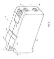
- the shape of the supply item is implicated by good engineering practices, including contemplation of a larger imaging context in which it is used.
- the supply item is generally rectangular and elongated from a back side 39 to a port side 41.
- the port side inserts forward in the direction of Arrow A into a container slot 200 in an imaging device, while the back side is acted upon by users for pushing.
- the shape also includes substantially symmetrical interior and exterior halves IH1, IH2 and EH1, EH2.
- the exterior halves EH1, EH2 join together by snap-fitting, welding, etc. at a seam (S) about the interior halves IH1, IH2 on opposite sides of the central support 40.
- the exterior halves are rigid to maintain the external shape of the housing of the supply item and are durable over a lifetime.
- Their material is any of a variety, but is selected from plastic, glass, metal, etc. and is based on criteria, such as cost, ease of manufacturing, shipping, storage, etc.
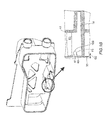
- a notch 225 Along a top exterior surface 210 of the housing is a notch 225.
- the notch mates with a rotating latch of the imaging device to keep in place the supply item during use.
- the notch 225 has a first face 227 to engage a front 231 of the latch and a second face 229 to engage a side 233 of the latch.
- the first face is angled relative to the top exterior surface to allow the latch 300 to swing into and away from contact with the notch (Action Arrow B) while the second face substantially parallels the side of the latch when the latch is engaged with the first face.
- the notch is positioned on the housing such that a force vector (F') from the latch perpendicular to the front face of the notch is aligned to bias forward the port side 41 of the housing that gets inserted first into the imaging device where the fluid exit port resides.
- This securely seats the housing in the imaging device and keeps the exit and air venting ports 20, 22 engaged with the imaging device to flow the volume of fluid to the imaging device without leaking.
- a biasing member 300 of the imaging device pushes upon the supply item at a space between the two ports 20, 22 to eject backward (Action Arrow D) the supply item a sufficient distance to clear the latch from engagement with the notch. Users then engage (pinch) a grasping handle 310 on the back side of the housing to retract fully the supply item from the container slot 200.
- a distance D4 between a center of the fluid exit port 20 and a center of the air venting port 22 is maintained in a range of about 25 mm - 27 mm.
- the center of the fluid exit port resides no more than 20 mm above a bottom surface 355 to minimize stranding the volume of ink in the interior (D3).
- a keying structure 330 resides on the housing to coordinate colors in the supply item with proper container slots based on ink, e.g., 200C, 200M, 200Y.
- a chamfer 350 along the length of the bottom serves as a further locating feature for seating the housing a proper container slot.
- the top exterior surface 210 of the housing is substantially flat and each of the first and second faces of the notch 225 angle from it in substantially differing amounts.
- the first face angles ( ⁇ ) from the top surface in a range of about 124 to about 127 degrees.
- the second face angles ( ⁇ ) from the top surface in a range of about 152 to about 155 degrees.
- the first and second faces define an angle ( ⁇ ) between them in an amount of more than 90 degrees to prevent the latch from binding or catching during de-latching of the supply item and more precisely about 98 to 100 degrees (99.4 degrees optimum).
- the second face of the notch is longer than the front face (D2>D1).
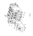
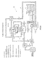
- FIG. 6 a schematic view is given of an ink container 10 deployed in an imaging device 100. Fluid paths extend from the fluid exit port 20 and air vent port 22. The fluid is delivered in a channel 75 to a printhead 80 (PH) for ejection from nozzles 82 for imaging media. The printhead is of the permanent or semi-permanent type. The supply item container is replaced numerous times over the life of the imaging device. At port 22, the container 10 is vented to atmosphere.
- Relatively apparent advantages of the many embodiments include, but are not limited to: (1) delivering essentially all the fluid in a container to an imaging device; (2) delivering the fluid in such a manner that the pigment concentration of the ink exiting the container has uniform properties over the lifetime of the container; (3) providing a mixing chamber at little cost to the container design; (4) providing passive mixing of pigmented ink without needing mechanical stir bars or other complex mechanisms; and (5) appropriately interfacing the container with an imaging device.
Landscapes
- Ink Jet (AREA)
- Details Of Rigid Or Semi-Rigid Containers (AREA)
Applications Claiming Priority (4)
| Application Number | Priority Date | Filing Date | Title |
|---|---|---|---|
| US40806510P | 2010-10-29 | 2010-10-29 | |
| US12/948,122 US8491107B2 (en) | 2010-10-29 | 2010-11-17 | Fluid container having mixing chambers for micro-fluid applications |
| US13/234,660 US8752941B2 (en) | 2010-11-17 | 2011-09-16 | Fluid container having latching interface for micro-fluid applications |
| EP11186892.3A EP2447078B1 (de) | 2010-10-29 | 2011-10-27 | Flüssigkeitsbehälter mit Laschenschnittstelle für mikrofluidische Anwendungen |
Related Parent Applications (2)
| Application Number | Title | Priority Date | Filing Date |
|---|---|---|---|
| EP11186892.3A Division EP2447078B1 (de) | 2010-10-29 | 2011-10-27 | Flüssigkeitsbehälter mit Laschenschnittstelle für mikrofluidische Anwendungen |
| EP11186892.3A Division-Into EP2447078B1 (de) | 2010-10-29 | 2011-10-27 | Flüssigkeitsbehälter mit Laschenschnittstelle für mikrofluidische Anwendungen |
Publications (3)
| Publication Number | Publication Date |
|---|---|
| EP2995460A2 true EP2995460A2 (de) | 2016-03-16 |
| EP2995460A3 EP2995460A3 (de) | 2016-10-26 |
| EP2995460B1 EP2995460B1 (de) | 2020-01-15 |
Family
ID=46047381
Family Applications (2)
| Application Number | Title | Priority Date | Filing Date |
|---|---|---|---|
| EP11186892.3A Active EP2447078B1 (de) | 2010-10-29 | 2011-10-27 | Flüssigkeitsbehälter mit Laschenschnittstelle für mikrofluidische Anwendungen |
| EP15185920.4A Active EP2995460B1 (de) | 2010-10-29 | 2011-10-27 | Flüssigkeitsbehälter mit arretierungsschnittstelle für mikrofluidische anwendungen |
Family Applications Before (1)
| Application Number | Title | Priority Date | Filing Date |
|---|---|---|---|
| EP11186892.3A Active EP2447078B1 (de) | 2010-10-29 | 2011-10-27 | Flüssigkeitsbehälter mit Laschenschnittstelle für mikrofluidische Anwendungen |
Country Status (4)
| Country | Link |
|---|---|
| US (1) | US8752941B2 (de) |
| EP (2) | EP2447078B1 (de) |
| CN (1) | CN102658723B (de) |
| CA (1) | CA2763339A1 (de) |
Cited By (1)
| Publication number | Priority date | Publication date | Assignee | Title |
|---|---|---|---|---|
| EP3501835A1 (de) * | 2017-12-20 | 2019-06-26 | OCE Holding B.V. | Tintenreservoir zur bereitstellung von tinte an einen druckkopf eines tintenstrahldruckers |
Families Citing this family (1)
| Publication number | Priority date | Publication date | Assignee | Title |
|---|---|---|---|---|
| US9662895B1 (en) * | 2016-06-21 | 2017-05-30 | Seiko Epson Corporation | Liquid container and liquid supply apparatus |
Family Cites Families (19)
| Publication number | Priority date | Publication date | Assignee | Title |
|---|---|---|---|---|
| US5825387A (en) | 1995-04-27 | 1998-10-20 | Hewlett-Packard Company | Ink supply for an ink-jet printer |
| US6494630B2 (en) | 1999-10-31 | 2002-12-17 | Hewlett-Packard Company | Datum structure for compact print cartridge |
| US6227663B1 (en) * | 2000-01-05 | 2001-05-08 | Hewlett-Packard Company | Ink-jet print cartridge having a low profile |
| US6457821B1 (en) * | 2001-03-13 | 2002-10-01 | Hewlett-Packard Company | Filter carrier for protecting a filter from being blocked by air bubbles in an inkjet printhead |
| US7585123B2 (en) * | 2001-08-22 | 2009-09-08 | Brother Kogyo Kabushiki Kaisha | Image forming apparatus |
| US6481829B1 (en) | 2001-09-18 | 2002-11-19 | Lexmark International, Inc. | Manually actuated carrier latch mechanism |
| JP3624950B2 (ja) | 2002-11-26 | 2005-03-02 | セイコーエプソン株式会社 | インクカートリッジ |
| US7055941B2 (en) * | 2003-02-14 | 2006-06-06 | Canon Kabushiki Kaisha | Liquid storage container, and liquid discharge recording apparatus using the container |
| JP3995015B2 (ja) | 2003-05-09 | 2007-10-24 | セイコーエプソン株式会社 | 液体噴射装置 |
| US7442180B2 (en) * | 2003-06-10 | 2008-10-28 | Hewlett-Packard Development Company, L.P. | Apparatus and methods for administering bioactive compositions |
| MXPA04012988A (es) | 2003-12-22 | 2005-10-18 | Seiko Epson Corp | Aparato para montar/desmontar un cartucho de tinta, aparato de registro, aparato para expulsion de liquidos y contenedor de liquidos. |
| JP3840237B2 (ja) * | 2004-06-02 | 2006-11-01 | キヤノン株式会社 | 液体収納容器および該液体収納容器を用いた記録装置 |
| US7159973B2 (en) * | 2004-06-10 | 2007-01-09 | Lexmark International, Inc. | Latch release mechanism for printing apparatus components |
| US7360879B2 (en) * | 2004-07-29 | 2008-04-22 | Castle Steven T | Inkjet pen adapter |
| EP1772271B1 (de) | 2005-09-29 | 2008-08-13 | Brother Kogyo Kabushiki Kaisha | Tintenpatrone und Tintenstrahlaufzeichnungsgerät |
| AU310075S (en) * | 2005-11-18 | 2006-09-18 | Brother Ind Ltd | Ink cartridge |
| USD542343S1 (en) * | 2005-11-18 | 2007-05-08 | Brother Industries, Ltd. | Ink cartridge |
| JP4916190B2 (ja) * | 2006-03-03 | 2012-04-11 | キヤノン株式会社 | インクタンクおよびプリンタ |
| DK2039521T4 (da) | 2008-02-28 | 2014-05-05 | Brother Ind Ltd | Blækpatron |
-
2011
- 2011-09-16 US US13/234,660 patent/US8752941B2/en active Active
- 2011-10-27 EP EP11186892.3A patent/EP2447078B1/de active Active
- 2011-10-27 EP EP15185920.4A patent/EP2995460B1/de active Active
- 2011-10-28 CN CN201110463176.7A patent/CN102658723B/zh active Active
-
2012
- 2012-01-05 CA CA2763339A patent/CA2763339A1/en not_active Abandoned
Cited By (1)
| Publication number | Priority date | Publication date | Assignee | Title |
|---|---|---|---|---|
| EP3501835A1 (de) * | 2017-12-20 | 2019-06-26 | OCE Holding B.V. | Tintenreservoir zur bereitstellung von tinte an einen druckkopf eines tintenstrahldruckers |
Also Published As
| Publication number | Publication date |
|---|---|
| CN102658723B (zh) | 2016-01-06 |
| US20120120164A1 (en) | 2012-05-17 |
| CA2763339A1 (en) | 2013-03-16 |
| EP2995460B1 (de) | 2020-01-15 |
| EP2995460A3 (de) | 2016-10-26 |
| EP2447078B1 (de) | 2015-12-30 |
| EP2447078A1 (de) | 2012-05-02 |
| CN102658723A (zh) | 2012-09-12 |
| US8752941B2 (en) | 2014-06-17 |
Similar Documents
| Publication | Publication Date | Title |
|---|---|---|
| EP2447079B1 (de) | Flüssigkeitsbehälter mit Fluidschnittstelle für mikrofluidische Anwendungen | |
| AU2011244868A1 (en) | Fluid container having fluid interface for micro-fluid applications | |
| CN202144145U (zh) | 液体收纳容器和液体喷射系统 | |
| CN103895360B (zh) | 液体收容容器、液体喷射系统、以及液体供给系统 | |
| CN1663803B (zh) | 墨盒和填充墨盒的方法 | |
| KR20020066202A (ko) | 액체 용기와, 이를 활용한 액체 공급 시스템 및 잉크 제트기록 장치와, 기록 장치 상에 액체 용기를 장착하는 방법 | |
| CN104608495A (zh) | 罐单元以及具有罐单元的液体喷射系统 | |
| CN102336062B (zh) | 液体收纳容器、液体喷射系统以及液体供给系统 | |
| US8544991B2 (en) | Consumable supply item, fluid reservoir and recirculation system for micro-fluid applications | |
| JP6627870B2 (ja) | プリントヘッドアセンブリおよびインクジェットプリンタ | |
| EP2995460B1 (de) | Flüssigkeitsbehälter mit arretierungsschnittstelle für mikrofluidische anwendungen | |
| US8590756B2 (en) | Container with tube drawing desired fluid concentrations for micro-fluid applications | |
| US9156272B2 (en) | Liquid supply apparatus for avoiding erroneous installation of liquid cartridge, printer provided with the same and liquid cartridge for the same | |
| US20120169813A1 (en) | Consumable supply item, fluid reservoir and recirculation system for micro-fluid applications | |
| CN102815093A (zh) | 微流体应用的带有流体接合部的流体容器 | |
| JP2006102971A (ja) | 液体噴射装置 | |
| US8430485B2 (en) | Liquid ejecting apparatus | |
| HK1179574A (en) | Fluid container having fluid interface for micro-fluid applications | |
| US20250326227A1 (en) | Liquid storage bottle and liquid replenishment system | |
| JP2007261161A (ja) | インクジェット記録装置のインク供給ユニット | |
| JP4010125B2 (ja) | インクカートリッジおよびこれを用いたインクジェット式記録装置 | |
| US20230054818A1 (en) | Continuous fluid recirculation and recirculation on-demand prior to firing for thermal ejection of fluid having concentration of solids |
Legal Events
| Date | Code | Title | Description |
|---|---|---|---|
| PUAI | Public reference made under article 153(3) epc to a published international application that has entered the european phase |
Free format text: ORIGINAL CODE: 0009012 |
|
| AC | Divisional application: reference to earlier application |
Ref document number: 2447078 Country of ref document: EP Kind code of ref document: P |
|
| AK | Designated contracting states |
Kind code of ref document: A2 Designated state(s): AL AT BE BG CH CY CZ DE DK EE ES FI FR GB GR HR HU IE IS IT LI LT LU LV MC MK MT NL NO PL PT RO RS SE SI SK SM TR |
|
| PUAL | Search report despatched |
Free format text: ORIGINAL CODE: 0009013 |
|
| AK | Designated contracting states |
Kind code of ref document: A3 Designated state(s): AL AT BE BG CH CY CZ DE DK EE ES FI FR GB GR HR HU IE IS IT LI LT LU LV MC MK MT NL NO PL PT RO RS SE SI SK SM TR |
|
| RIC1 | Information provided on ipc code assigned before grant |
Ipc: B41J 2/175 20060101AFI20160921BHEP |
|
| 17P | Request for examination filed |
Effective date: 20170426 |
|
| RBV | Designated contracting states (corrected) |
Designated state(s): AL AT BE BG CH CY CZ DE DK EE ES FI FR GB GR HR HU IE IS IT LI LT LU LV MC MK MT NL NO PL PT RO RS SE SI SK SM TR |
|
| STAA | Information on the status of an ep patent application or granted ep patent |
Free format text: STATUS: REQUEST FOR EXAMINATION WAS MADE |
|
| GRAP | Despatch of communication of intention to grant a patent |
Free format text: ORIGINAL CODE: EPIDOSNIGR1 |
|
| STAA | Information on the status of an ep patent application or granted ep patent |
Free format text: STATUS: GRANT OF PATENT IS INTENDED |
|
| INTG | Intention to grant announced |
Effective date: 20190808 |
|
| RIN1 | Information on inventor provided before grant (corrected) |
Inventor name: WILLIAMSON, RANDAL S. Inventor name: JAMES III, EDMUND H. Inventor name: KOMPLIN, STEVEN R. |
|
| GRAS | Grant fee paid |
Free format text: ORIGINAL CODE: EPIDOSNIGR3 |
|
| GRAA | (expected) grant |
Free format text: ORIGINAL CODE: 0009210 |
|
| STAA | Information on the status of an ep patent application or granted ep patent |
Free format text: STATUS: THE PATENT HAS BEEN GRANTED |
|
| AC | Divisional application: reference to earlier application |
Ref document number: 2447078 Country of ref document: EP Kind code of ref document: P |
|
| AK | Designated contracting states |
Kind code of ref document: B1 Designated state(s): AL AT BE BG CH CY CZ DE DK EE ES FI FR GB GR HR HU IE IS IT LI LT LU LV MC MK MT NL NO PL PT RO RS SE SI SK SM TR |
|
| REG | Reference to a national code |
Ref country code: CH Ref legal event code: EP Ref country code: GB Ref legal event code: FG4D |
|
| REG | Reference to a national code |
Ref country code: IE Ref legal event code: FG4D |
|
| REG | Reference to a national code |
Ref country code: DE Ref legal event code: R096 Ref document number: 602011064692 Country of ref document: DE |
|
| REG | Reference to a national code |
Ref country code: AT Ref legal event code: REF Ref document number: 1224811 Country of ref document: AT Kind code of ref document: T Effective date: 20200215 |
|
| REG | Reference to a national code |
Ref country code: NL Ref legal event code: MP Effective date: 20200115 |
|
| REG | Reference to a national code |
Ref country code: LT Ref legal event code: MG4D |
|
| PG25 | Lapsed in a contracting state [announced via postgrant information from national office to epo] |
Ref country code: PT Free format text: LAPSE BECAUSE OF FAILURE TO SUBMIT A TRANSLATION OF THE DESCRIPTION OR TO PAY THE FEE WITHIN THE PRESCRIBED TIME-LIMIT Effective date: 20200607 Ref country code: NO Free format text: LAPSE BECAUSE OF FAILURE TO SUBMIT A TRANSLATION OF THE DESCRIPTION OR TO PAY THE FEE WITHIN THE PRESCRIBED TIME-LIMIT Effective date: 20200415 Ref country code: NL Free format text: LAPSE BECAUSE OF FAILURE TO SUBMIT A TRANSLATION OF THE DESCRIPTION OR TO PAY THE FEE WITHIN THE PRESCRIBED TIME-LIMIT Effective date: 20200115 Ref country code: FI Free format text: LAPSE BECAUSE OF FAILURE TO SUBMIT A TRANSLATION OF THE DESCRIPTION OR TO PAY THE FEE WITHIN THE PRESCRIBED TIME-LIMIT Effective date: 20200115 Ref country code: RS Free format text: LAPSE BECAUSE OF FAILURE TO SUBMIT A TRANSLATION OF THE DESCRIPTION OR TO PAY THE FEE WITHIN THE PRESCRIBED TIME-LIMIT Effective date: 20200115 |
|
| PG25 | Lapsed in a contracting state [announced via postgrant information from national office to epo] |
Ref country code: BG Free format text: LAPSE BECAUSE OF FAILURE TO SUBMIT A TRANSLATION OF THE DESCRIPTION OR TO PAY THE FEE WITHIN THE PRESCRIBED TIME-LIMIT Effective date: 20200415 Ref country code: GR Free format text: LAPSE BECAUSE OF FAILURE TO SUBMIT A TRANSLATION OF THE DESCRIPTION OR TO PAY THE FEE WITHIN THE PRESCRIBED TIME-LIMIT Effective date: 20200416 Ref country code: IS Free format text: LAPSE BECAUSE OF FAILURE TO SUBMIT A TRANSLATION OF THE DESCRIPTION OR TO PAY THE FEE WITHIN THE PRESCRIBED TIME-LIMIT Effective date: 20200515 Ref country code: HR Free format text: LAPSE BECAUSE OF FAILURE TO SUBMIT A TRANSLATION OF THE DESCRIPTION OR TO PAY THE FEE WITHIN THE PRESCRIBED TIME-LIMIT Effective date: 20200115 Ref country code: LV Free format text: LAPSE BECAUSE OF FAILURE TO SUBMIT A TRANSLATION OF THE DESCRIPTION OR TO PAY THE FEE WITHIN THE PRESCRIBED TIME-LIMIT Effective date: 20200115 Ref country code: SE Free format text: LAPSE BECAUSE OF FAILURE TO SUBMIT A TRANSLATION OF THE DESCRIPTION OR TO PAY THE FEE WITHIN THE PRESCRIBED TIME-LIMIT Effective date: 20200115 |
|
| REG | Reference to a national code |
Ref country code: DE Ref legal event code: R097 Ref document number: 602011064692 Country of ref document: DE |
|
| PG25 | Lapsed in a contracting state [announced via postgrant information from national office to epo] |
Ref country code: ES Free format text: LAPSE BECAUSE OF FAILURE TO SUBMIT A TRANSLATION OF THE DESCRIPTION OR TO PAY THE FEE WITHIN THE PRESCRIBED TIME-LIMIT Effective date: 20200115 Ref country code: CZ Free format text: LAPSE BECAUSE OF FAILURE TO SUBMIT A TRANSLATION OF THE DESCRIPTION OR TO PAY THE FEE WITHIN THE PRESCRIBED TIME-LIMIT Effective date: 20200115 Ref country code: LT Free format text: LAPSE BECAUSE OF FAILURE TO SUBMIT A TRANSLATION OF THE DESCRIPTION OR TO PAY THE FEE WITHIN THE PRESCRIBED TIME-LIMIT Effective date: 20200115 Ref country code: RO Free format text: LAPSE BECAUSE OF FAILURE TO SUBMIT A TRANSLATION OF THE DESCRIPTION OR TO PAY THE FEE WITHIN THE PRESCRIBED TIME-LIMIT Effective date: 20200115 Ref country code: SM Free format text: LAPSE BECAUSE OF FAILURE TO SUBMIT A TRANSLATION OF THE DESCRIPTION OR TO PAY THE FEE WITHIN THE PRESCRIBED TIME-LIMIT Effective date: 20200115 Ref country code: EE Free format text: LAPSE BECAUSE OF FAILURE TO SUBMIT A TRANSLATION OF THE DESCRIPTION OR TO PAY THE FEE WITHIN THE PRESCRIBED TIME-LIMIT Effective date: 20200115 Ref country code: DK Free format text: LAPSE BECAUSE OF FAILURE TO SUBMIT A TRANSLATION OF THE DESCRIPTION OR TO PAY THE FEE WITHIN THE PRESCRIBED TIME-LIMIT Effective date: 20200115 Ref country code: SK Free format text: LAPSE BECAUSE OF FAILURE TO SUBMIT A TRANSLATION OF THE DESCRIPTION OR TO PAY THE FEE WITHIN THE PRESCRIBED TIME-LIMIT Effective date: 20200115 |
|
| REG | Reference to a national code |
Ref country code: AT Ref legal event code: MK05 Ref document number: 1224811 Country of ref document: AT Kind code of ref document: T Effective date: 20200115 |
|
| PLBE | No opposition filed within time limit |
Free format text: ORIGINAL CODE: 0009261 |
|
| STAA | Information on the status of an ep patent application or granted ep patent |
Free format text: STATUS: NO OPPOSITION FILED WITHIN TIME LIMIT |
|
| 26N | No opposition filed |
Effective date: 20201016 |
|
| PG25 | Lapsed in a contracting state [announced via postgrant information from national office to epo] |
Ref country code: IT Free format text: LAPSE BECAUSE OF FAILURE TO SUBMIT A TRANSLATION OF THE DESCRIPTION OR TO PAY THE FEE WITHIN THE PRESCRIBED TIME-LIMIT Effective date: 20200115 Ref country code: AT Free format text: LAPSE BECAUSE OF FAILURE TO SUBMIT A TRANSLATION OF THE DESCRIPTION OR TO PAY THE FEE WITHIN THE PRESCRIBED TIME-LIMIT Effective date: 20200115 |
|
| PG25 | Lapsed in a contracting state [announced via postgrant information from national office to epo] |
Ref country code: PL Free format text: LAPSE BECAUSE OF FAILURE TO SUBMIT A TRANSLATION OF THE DESCRIPTION OR TO PAY THE FEE WITHIN THE PRESCRIBED TIME-LIMIT Effective date: 20200115 Ref country code: SI Free format text: LAPSE BECAUSE OF FAILURE TO SUBMIT A TRANSLATION OF THE DESCRIPTION OR TO PAY THE FEE WITHIN THE PRESCRIBED TIME-LIMIT Effective date: 20200115 |
|
| REG | Reference to a national code |
Ref country code: CH Ref legal event code: PL |
|
| GBPC | Gb: european patent ceased through non-payment of renewal fee |
Effective date: 20201027 |
|
| PG25 | Lapsed in a contracting state [announced via postgrant information from national office to epo] |
Ref country code: LU Free format text: LAPSE BECAUSE OF NON-PAYMENT OF DUE FEES Effective date: 20201027 Ref country code: MC Free format text: LAPSE BECAUSE OF FAILURE TO SUBMIT A TRANSLATION OF THE DESCRIPTION OR TO PAY THE FEE WITHIN THE PRESCRIBED TIME-LIMIT Effective date: 20200115 |
|
| REG | Reference to a national code |
Ref country code: BE Ref legal event code: MM Effective date: 20201031 |
|
| PG25 | Lapsed in a contracting state [announced via postgrant information from national office to epo] |
Ref country code: FR Free format text: LAPSE BECAUSE OF NON-PAYMENT OF DUE FEES Effective date: 20201031 |
|
| PG25 | Lapsed in a contracting state [announced via postgrant information from national office to epo] |
Ref country code: BE Free format text: LAPSE BECAUSE OF NON-PAYMENT OF DUE FEES Effective date: 20201031 Ref country code: CH Free format text: LAPSE BECAUSE OF NON-PAYMENT OF DUE FEES Effective date: 20201031 Ref country code: LI Free format text: LAPSE BECAUSE OF NON-PAYMENT OF DUE FEES Effective date: 20201031 Ref country code: GB Free format text: LAPSE BECAUSE OF NON-PAYMENT OF DUE FEES Effective date: 20201027 |
|
| PG25 | Lapsed in a contracting state [announced via postgrant information from national office to epo] |
Ref country code: IE Free format text: LAPSE BECAUSE OF NON-PAYMENT OF DUE FEES Effective date: 20201027 |
|
| PG25 | Lapsed in a contracting state [announced via postgrant information from national office to epo] |
Ref country code: TR Free format text: LAPSE BECAUSE OF FAILURE TO SUBMIT A TRANSLATION OF THE DESCRIPTION OR TO PAY THE FEE WITHIN THE PRESCRIBED TIME-LIMIT Effective date: 20200115 Ref country code: MT Free format text: LAPSE BECAUSE OF FAILURE TO SUBMIT A TRANSLATION OF THE DESCRIPTION OR TO PAY THE FEE WITHIN THE PRESCRIBED TIME-LIMIT Effective date: 20200115 Ref country code: CY Free format text: LAPSE BECAUSE OF FAILURE TO SUBMIT A TRANSLATION OF THE DESCRIPTION OR TO PAY THE FEE WITHIN THE PRESCRIBED TIME-LIMIT Effective date: 20200115 |
|
| PG25 | Lapsed in a contracting state [announced via postgrant information from national office to epo] |
Ref country code: MK Free format text: LAPSE BECAUSE OF FAILURE TO SUBMIT A TRANSLATION OF THE DESCRIPTION OR TO PAY THE FEE WITHIN THE PRESCRIBED TIME-LIMIT Effective date: 20200115 Ref country code: AL Free format text: LAPSE BECAUSE OF FAILURE TO SUBMIT A TRANSLATION OF THE DESCRIPTION OR TO PAY THE FEE WITHIN THE PRESCRIBED TIME-LIMIT Effective date: 20200115 |
|
| PGFP | Annual fee paid to national office [announced via postgrant information from national office to epo] |
Ref country code: DE Payment date: 20250307 Year of fee payment: 14 |