EP2995355A1 - Exercise device providing adjustable pace length - Google Patents
Exercise device providing adjustable pace length Download PDFInfo
- Publication number
- EP2995355A1 EP2995355A1 EP14187888.4A EP14187888A EP2995355A1 EP 2995355 A1 EP2995355 A1 EP 2995355A1 EP 14187888 A EP14187888 A EP 14187888A EP 2995355 A1 EP2995355 A1 EP 2995355A1
- Authority
- EP
- European Patent Office
- Prior art keywords
- linkage
- arm
- swing
- pedal assembly
- couples
- Prior art date
- Legal status (The legal status is an assumption and is not a legal conclusion. Google has not performed a legal analysis and makes no representation as to the accuracy of the status listed.)
- Withdrawn
Links
Images


Classifications
-
- A—HUMAN NECESSITIES
- A63—SPORTS; GAMES; AMUSEMENTS
- A63B—APPARATUS FOR PHYSICAL TRAINING, GYMNASTICS, SWIMMING, CLIMBING, OR FENCING; BALL GAMES; TRAINING EQUIPMENT
- A63B22/00—Exercising apparatus specially adapted for conditioning the cardio-vascular system, for training agility or co-ordination of movements
- A63B22/0002—Exercising apparatus specially adapted for conditioning the cardio-vascular system, for training agility or co-ordination of movements involving an exercising of arms
- A63B22/001—Exercising apparatus specially adapted for conditioning the cardio-vascular system, for training agility or co-ordination of movements involving an exercising of arms by simultaneously exercising arms and legs, e.g. diagonally in anti-phase
-
- A—HUMAN NECESSITIES
- A63—SPORTS; GAMES; AMUSEMENTS
- A63B—APPARATUS FOR PHYSICAL TRAINING, GYMNASTICS, SWIMMING, CLIMBING, OR FENCING; BALL GAMES; TRAINING EQUIPMENT
- A63B22/00—Exercising apparatus specially adapted for conditioning the cardio-vascular system, for training agility or co-ordination of movements
- A63B22/0015—Exercising apparatus specially adapted for conditioning the cardio-vascular system, for training agility or co-ordination of movements with an adjustable movement path of the support elements
-
- A—HUMAN NECESSITIES
- A63—SPORTS; GAMES; AMUSEMENTS
- A63B—APPARATUS FOR PHYSICAL TRAINING, GYMNASTICS, SWIMMING, CLIMBING, OR FENCING; BALL GAMES; TRAINING EQUIPMENT
- A63B22/00—Exercising apparatus specially adapted for conditioning the cardio-vascular system, for training agility or co-ordination of movements
- A63B22/06—Exercising apparatus specially adapted for conditioning the cardio-vascular system, for training agility or co-ordination of movements with support elements performing a rotating cycling movement, i.e. a closed path movement
- A63B22/0664—Exercising apparatus specially adapted for conditioning the cardio-vascular system, for training agility or co-ordination of movements with support elements performing a rotating cycling movement, i.e. a closed path movement performing an elliptic movement
- A63B2022/0676—Exercising apparatus specially adapted for conditioning the cardio-vascular system, for training agility or co-ordination of movements with support elements performing a rotating cycling movement, i.e. a closed path movement performing an elliptic movement with crank and handles being on the same side of the exercising apparatus with respect to the frontal body-plane of the user, e.g. crank and handles are in front of the user
-
- A—HUMAN NECESSITIES
- A63—SPORTS; GAMES; AMUSEMENTS
- A63B—APPARATUS FOR PHYSICAL TRAINING, GYMNASTICS, SWIMMING, CLIMBING, OR FENCING; BALL GAMES; TRAINING EQUIPMENT
- A63B21/00—Exercising apparatus for developing or strengthening the muscles or joints of the body by working against a counterforce, with or without measuring devices
- A63B21/22—Resisting devices with rotary bodies
- A63B21/225—Resisting devices with rotary bodies with flywheels
-
- A—HUMAN NECESSITIES
- A63—SPORTS; GAMES; AMUSEMENTS
- A63B—APPARATUS FOR PHYSICAL TRAINING, GYMNASTICS, SWIMMING, CLIMBING, OR FENCING; BALL GAMES; TRAINING EQUIPMENT
- A63B22/00—Exercising apparatus specially adapted for conditioning the cardio-vascular system, for training agility or co-ordination of movements
- A63B22/20—Exercising apparatus specially adapted for conditioning the cardio-vascular system, for training agility or co-ordination of movements using rollers, wheels, castors or the like, e.g. gliding means, to be moved over the floor or other surface, e.g. guide tracks, during exercising
- A63B22/201—Exercising apparatus specially adapted for conditioning the cardio-vascular system, for training agility or co-ordination of movements using rollers, wheels, castors or the like, e.g. gliding means, to be moved over the floor or other surface, e.g. guide tracks, during exercising for moving a support element in reciprocating translation, i.e. for sliding back and forth on a guide track
- A63B22/203—Exercising apparatus specially adapted for conditioning the cardio-vascular system, for training agility or co-ordination of movements using rollers, wheels, castors or the like, e.g. gliding means, to be moved over the floor or other surface, e.g. guide tracks, during exercising for moving a support element in reciprocating translation, i.e. for sliding back and forth on a guide track in a horizontal plane
Definitions
- Taiwan Patent Application No. 103129132 filed on August 25, 2014 , from which this application claims priority, are incorporated herein by reference.
- the present invention relates to an exercise device, and more particularly relates to an exercise device providing adjustable pace length.
- An elliptical trainer also called a cross-trainer or an X-trainer, is a stationary exercise machine to simulate stair climbing, walking, or running.
- the elliptical trainer does not cause excessive pressure to the joints as the two legs simultaneously share the burden, hence decreasing the risk of impact injuries.
- the elliptical trainer typically includes two pedals. A user steps on the pedals and the operation of the elliptical trainer cause the pedals to provide a moving path. For conventional elliptical trainers, the moving path of the pedals is invariable.
- Taiwan Patent, Publication No., M403355 entitled “Rising Device for Elliptical Trainers,” discloses an elliptical trainer with a rising device that can adjust the path of the pedals. However, the distance between the two pedals, i.e., the pace length, is still fixed.
- Fig. 1 shows an elliptical trainer 1 having a fixed pace length of 20 inches. Because the users have varied heights, the elliptical trainer 1 could not suitable to all users, and the optimum training effect cannot be achieved.
- the present invention relates to an exercise device, and more particularly relates to exercise device providing elliptical or elliptical-like paths and adjustable pace lengths.
- an exercise device is provided with a frame, a rotational mechanism, a left coupling mechanism and a right coupling mechanism, and a pace-adjusting assembly.
- the frame comprises a supporting structure extended upward from a top portion of the frame.
- the rotational mechanism is placed at the supporting structure.
- the left coupling mechanism and the right coupling mechanism are respectively arranged at a side of the supporting structure.
- the left coupling mechanism and the right coupling mechanism has an end coupled with the rotational mechanism and another end coupled with a left pedal assembly and a right pedal assembly, respectively.
- the pace-adjusting assembly comprises a left linkage structure and a right linkage structure, a left swing structure and a right swing structure, and a driving device.
- the left linkage structure and the right linkage structure have an end coupled with the supporting structure and another end coupled with the left pedal assembly and the right pedal assembly, respectively.
- the left swing structure and the right swing structure comprises a wheel assembly through which the left linkage structure or the right linkage structure passes, and the left swing structure and the right swing structure have an end coupled with the supporting structure and another end coupled with the left pedal assembly and the right pedal assembly, respectively.
- the driving device couples with the left swing structure and the right swing structure for lifting or lowering the left swing structure and the right swing structure so as to determine a pace length.
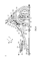
- a preferred embodiment of the present invention provides an exercise device 2 such as an elliptical trainer 2 in which the pace length can be adjusted.
- the elliptical trainer 2 comprises a frame 10, a left/right coupling mechanism 20a/20b, a left/right pace-adjusting mechanism 30a/30b, and a rotational mechanism 40.
- the left coupling mechanism 20a and the right coupling mechanism 20b have the same structure and are symmetrically arranged, in which "a" and “b" denote the left and right components respectively and may be omitted for simplicity.
- the left coupling mechanism 20a and/or the right coupling mechanism 20b can be referred to collectively as the coupling mechanism 20
- the left pace-adjusting mechanism 30a and/or the right pace-adjusting mechanism 30b can be referred to collectively as the pace-adjusting mechanism 30, and so on.
- Figs 3-5 merely show the right coupling mechanism 20b and the right pace-adjusting mechanism 30b, and omit the left coupling mechanism 20a and the left pace-adjusting mechanism 30a for clarity.
- the frame 10 is arranged on a supporting surface or ground.
- a supporting structure 11 is upwardly extended from the top of a front portion of the frame 10.
- the supporting structure 11 means stationary fixing mechanisms arranged at the front portion of the frame 10, for fixing the rotation mechanism 40, the coupling mechanism 40, the pace-adjusting mechanism 30, control panel, and the likes.
- the rear portion of the frame 10 has two tracks 13.
- the supporting structure 11 comprises an axis 111, and the left coupling mechanism 20a and the right coupling mechanism 20b are respectively arranged at a side of the supporting structure 11.
- the left coupling mechanism 20a and the light coupling mechanism 20b may comprise a crank 21, a supporting arm 23, a pedal assembly 25, a handrail 27, and a linkage 29, respectively.
- the supporting arm 23 may comprise a pivot portion 231, a sliding portion 233, and a supporting portion 235.
- the crank 21 has two ends, in which one end rotationally connected to the axis 111 and the other end pivotally coupled to the pivot portion 231 of the supporting arm 23.
- the sliding portion 233 is capable of sliding on the track 13 of the frame 10.
- Each pedal assembly 25 comprises a base 251, a pedal 253, and a slider 255.
- the base 251 pivotally connected with the supporting portion 235 and fixes with an end of the linkage 29.
- the handrail 27 comprises a pivot portion 271, a coupling portion 273, and a holding portion 275.
- the linkage 29 has two ends, in which one end couples to the base 251 of the pedal assembly and another end couples to the pivot portion 271 of the handrail 27.
- the holding portion can be held by the user's hand.
- the coupling portion 273 pivotally couples with the supporting structure 11, so that the handrail 27 can swing around the coupling portion 273.
- the rotational mechanism 40 is arranged at the supporting structure 11 and connects with the left and right pedal assembly 25a/25b via the left coupling mechanism 20a and the right coupling mechanisms 20a/20b, respectively.
- the user drives the rotational mechanism 40 via the pedal assembly 25, which will make a moving path, e.g., an elliptical or elliptical-like moving path.
- the rotational mechanism 40 may comprise, but is not limited to, a driving wheel 41 and a flywheel 43.
- the driving wheel 41 pivotally couples with the axis 111 of the supporting structure 11, and can be driven by the crank 31.
- the flywheel 43 couples to the front portion of the frame 10.
- the driving wheel 41 employs a coupling member (not shown), such as a belt, as a medium to drive the flywheel 43.
- each pace-adjusting mechanism 30, i.e., the left or the right pace-adjusting mechanism comprises a swing structure 31, a linkage structure 33, and a driving device 35.
- Each swing structure 31 comprises a head structure 311, a first swing arm 313, a wheel assembly 315, a second swing arm 317, and a third swing arm 319.
- the linkage structure 33 comprises a first linkage arm 331 and a second linkage arm 333.
- the driving device 35 can lift or lower the swing structure 31.
- the driving device 35 may comprise, but is not limited to, a motor 351, a screw 353, and an internally-thread tube 355.
- the internally-thread tube 355 has an end coupled with the head structure 311.
- the internally-thread tube 355 couples with the screw 353 via its thread.
- the motor 351 can drive the screw 353 to rotate, making the internally-thread tube 355 moving along with the screw 353 in a direction of approaching or leaving the motor 351.
- the head structure 311 has two ends in which one end couples the supporting structure 11 and the other end couples to an end of the first swing arm 313.
- a portion between two ends of the head structures pivotally couples with the internally-thread tube 355 of the driving device 35.
- the first swing arm 313 has two ends, in which one end couples with head structure 311, and the other end couples with an end of the wheel assembly 315, which fixes with the second swing arm 317.
- the second swing arm 317 has two ends, in which one end couples to the wheel assembly 315 and the other end couples to an end of the third swing arm 319.
- the third swing arm 319 has two ends, in which one end couples with second swing arm 317, and the other end pivotally couples with the supporting portion 235.
- the wheel assembly 315 is a hollowed structure and the first linkage arm 331 passes through the wheel assembly 315.
- the first linkage arm 331 has two ends, in which one end pivotally couples with a lever 112 of the supporting structure 11 and the other end couples with the second linkage arm 333.
- the second linkage arm 333 has two ends, in which one end pivotally couples with the first linkage arm 331 and the other end pivotally connects with the slider 255.
- the slider 255 fixes with the pedal 253, and the base 251 comprises a track 2511 on which the slider 255 can move forward or backward.
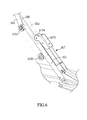
- Fig. 6 is a partially enlarged view showing the detail of the wheel assembly 315 according to the preferred embodiment of the present invention.
- the wheel assembly 315 has a hollowed housing coupled with the second swing arm 317, and the first linkage arm 331 passes through the hollowed housing.
- the wheel assembly 315 may have a plurality of wheels against the first linkage arm 331, so that the wheel assembly 315 can slide along the first linkage arm 331 smoothly.
- the wheel assembly 315 may have a first wheel 3151 and a second wheel 3153.
- the second swing arm 317 may have a hook 3172 pivotally coupled with an end of the second swing arm 317, and the hook 3172 has a third wheel 3174 against the first linkage arm 331.
- first wheel 3151 and the second wheel 3153 are arranged at a side of the first linkage arm 331, and the third wheel 3174 is arranged at the other side of the first linkage arm 331, so that the first linkage arm 331 are sandwiched by the first wheel 3151, the second wheel 3153, and the third wheel 3174.
- Modification may be made for the wheel assembly 315. In other embodiments, the number of the wheel is not limited, and the wheel assembly 315 could have different configuration.
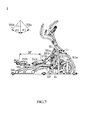
- Figs. 3 , 4 , and 5 merely show the right swing structure 31 and the right linkage structure 33, and omit the left swing structure 31 and the left linkage structure 33.
- Fig 7 and Fig. 8 show both of the left and right swing structure 31 and left/right swing structure 33.
- Fig. 7 when the head structure 33 is lifted, the angle ⁇ 1 between the left linkage arm 331a and the vertical direction of the supporting structure 11 is increased, and the angle ⁇ 2 between the right linkage arm 331b and the vertical direction of the supporting structure 11 is increased, too.
- the slider 255a moves forward, and the slider 255b moves backward. Therefore, the pace length between the two pedals is increased, e.g., increased to 24 inches.
- Fig. 7 shows the exercise device 2 with a maximum pace length
- Fig. 8 shows the exercise device 2 with a minimum pace length.
- the left and right swing structures 31 and the left and right linkage structures 33 are placed between the supporting structure 11 and the pedal assembly 25 and not couple with the cranks 21. Therefore, when changing the pace length, the transverse diameter of the elliptical or elliptical-like moving path will be increased or decreased, and the user needs not to raise his or her legs.
- the posture is ergonomic and the device can fit varied users.
Landscapes
- Health & Medical Sciences (AREA)
- Cardiology (AREA)
- Vascular Medicine (AREA)
- General Health & Medical Sciences (AREA)
- Physical Education & Sports Medicine (AREA)
- Rehabilitation Tools (AREA)
Applications Claiming Priority (1)
| Application Number | Priority Date | Filing Date | Title |
|---|---|---|---|
| TW103129132A TWI542382B (zh) | 2014-08-25 | 2014-08-25 | 可調整行程跨距的運動裝置 |
Publications (1)
| Publication Number | Publication Date |
|---|---|
| EP2995355A1 true EP2995355A1 (en) | 2016-03-16 |
Family
ID=51690851
Family Applications (1)
| Application Number | Title | Priority Date | Filing Date |
|---|---|---|---|
| EP14187888.4A Withdrawn EP2995355A1 (en) | 2014-08-25 | 2014-10-07 | Exercise device providing adjustable pace length |
Country Status (3)
| Country | Link |
|---|---|
| US (1) | US9199116B1 (zh) |
| EP (1) | EP2995355A1 (zh) |
| TW (1) | TWI542382B (zh) |
Families Citing this family (6)
| Publication number | Priority date | Publication date | Assignee | Title |
|---|---|---|---|---|
| US11033767B2 (en) * | 2017-01-03 | 2021-06-15 | Engen Fitness, Inc. | Guided movement exercise machine |
| TWI621463B (zh) * | 2017-03-16 | 2018-04-21 | 力伽實業股份有限公司 | 手足複合式運動機 |
| TWI693086B (zh) * | 2019-05-22 | 2020-05-11 | 肯尼實業有限公司 | 橢圓機的結構 |
| US11673019B2 (en) * | 2020-03-03 | 2023-06-13 | Nautilus, Inc. | Elliptical exercise machine |
| TWI710392B (zh) * | 2020-03-23 | 2020-11-21 | 鼎固健康科技股份有限公司 | 橢圓健身機之電動式行程軌跡調整結構 |
| TWI783411B (zh) * | 2021-03-17 | 2022-11-11 | 力山工業股份有限公司 | 具坡度調整功能的爬坡機 |
Citations (5)
| Publication number | Priority date | Publication date | Assignee | Title |
|---|---|---|---|---|
| US20070238580A1 (en) * | 2006-03-29 | 2007-10-11 | Leao Wang | Pace-adjusting mechanism of an elliptical cross trainer |
| TWM403355U (en) | 2010-12-21 | 2011-05-11 | Dyaco Int Inc | Escalating apparatus of elliptical exercise machine |
| CN201921387U (zh) * | 2010-11-29 | 2011-08-10 | 力伽实业股份有限公司 | 运动机 |
| TWM458233U (zh) * | 2013-02-25 | 2013-08-01 | Dyaco Int Inc | 可改變行程之橢圓機 |
| DE202014101840U1 (de) * | 2014-02-26 | 2014-05-02 | Dyaco International Inc. | Trainingsgerät mit einem verstellbaren Schrittabstand |
Family Cites Families (16)
| Publication number | Priority date | Publication date | Assignee | Title |
|---|---|---|---|---|
| US3432164A (en) * | 1967-02-14 | 1969-03-11 | Hugh A Deeks | Exercising machine |
| US5611758A (en) * | 1996-05-15 | 1997-03-18 | Ccs, Llc | Recumbent exercise apparatus |
| US5947872A (en) * | 1996-06-17 | 1999-09-07 | Brunswick Corporation | Cross training exercise apparatus |
| US7041034B1 (en) * | 1997-04-24 | 2006-05-09 | Stearns Kenneth W | Elliptical exercise methods and apparatus |
| US6689019B2 (en) * | 2001-03-30 | 2004-02-10 | Nautilus, Inc. | Exercise machine |
| US7811205B2 (en) * | 2002-10-09 | 2010-10-12 | The Shifter, Inc. | Spontaneous symmetrical weight shifting trainer device |
| US7731634B2 (en) * | 2005-02-09 | 2010-06-08 | Precor Incorporated | Elliptical exercise equipment with stowable arms |
| TWM283655U (en) | 2005-08-19 | 2005-12-21 | Cycling & Health Tech Ind R&D | Elliptic sport machine with orbit-adjusting function |
| TWM284406U (en) | 2005-09-02 | 2006-01-01 | Chia Ting Foundries Co Ltd | Elliptical exercise machine |
| US7927258B2 (en) * | 2007-08-17 | 2011-04-19 | Real Ryder, LLC | Bicycling exercise apparatus |
| EP2432680A4 (en) * | 2009-05-19 | 2014-07-30 | Pt Motion Works Inc | ADJUSTABLE CRANK ARM FOR ELLIPTICAL BIKE AND METHOD OF USE |
| CN201572487U (zh) | 2009-12-09 | 2010-09-08 | 旭凯国际股份有限公司 | 可调跨距椭圆漫步机 |
| US8628454B2 (en) | 2011-06-20 | 2014-01-14 | Strength Master Fitness Tech Co., Ltd. | Sports training machine and control method thereof |
| EP2537566A1 (en) | 2011-06-24 | 2012-12-26 | Strength Master Fitness Tech Co., Ltd. | Sports training machine and control method thereof |
| US8840529B2 (en) * | 2012-03-14 | 2014-09-23 | Yi-Tzu Chen | Adjustable elliptical trainer |
| CN203763774U (zh) | 2014-03-25 | 2014-08-13 | 岱宇国际股份有限公司 | 可调整行程跨距的运动装置 |
-
2014
- 2014-08-25 TW TW103129132A patent/TWI542382B/zh active
- 2014-09-25 US US14/497,025 patent/US9199116B1/en active Active
- 2014-10-07 EP EP14187888.4A patent/EP2995355A1/en not_active Withdrawn
Patent Citations (5)
| Publication number | Priority date | Publication date | Assignee | Title |
|---|---|---|---|---|
| US20070238580A1 (en) * | 2006-03-29 | 2007-10-11 | Leao Wang | Pace-adjusting mechanism of an elliptical cross trainer |
| CN201921387U (zh) * | 2010-11-29 | 2011-08-10 | 力伽实业股份有限公司 | 运动机 |
| TWM403355U (en) | 2010-12-21 | 2011-05-11 | Dyaco Int Inc | Escalating apparatus of elliptical exercise machine |
| TWM458233U (zh) * | 2013-02-25 | 2013-08-01 | Dyaco Int Inc | 可改變行程之橢圓機 |
| DE202014101840U1 (de) * | 2014-02-26 | 2014-05-02 | Dyaco International Inc. | Trainingsgerät mit einem verstellbaren Schrittabstand |
Also Published As
| Publication number | Publication date |
|---|---|
| TWI542382B (zh) | 2016-07-21 |
| US9199116B1 (en) | 2015-12-01 |
| TW201607585A (zh) | 2016-03-01 |
Similar Documents
| Publication | Publication Date | Title |
|---|---|---|
| US9259610B2 (en) | Exercise device providing adjustable step distance | |
| EP2995355A1 (en) | Exercise device providing adjustable pace length | |
| EP2889056A1 (en) | Exercise device providing elliptical exercising paths | |
| US9186541B1 (en) | Elliptical trainer | |
| US9254414B2 (en) | Exercise device | |
| US9452315B1 (en) | Treadmill | |
| US9849332B1 (en) | Exercise device | |
| US9649529B1 (en) | Elliptical exercise device with moving control tracks | |
| US9566466B2 (en) | Exercise device | |
| US9295874B1 (en) | Elliptical trainer | |
| US10632341B2 (en) | Climbing machine | |
| US9604098B2 (en) | Exercise device | |
| US10518128B2 (en) | Elliptical trainer | |
| US9539464B1 (en) | Exercise device | |
| WO2016029331A1 (zh) | 可调整行程跨距的运动装置 | |
| CN107802986B (zh) | 运动装置 | |
| US9643045B2 (en) | Exercise device | |
| TWI556854B (zh) | 運動裝置 | |
| TWM568717U (zh) | 攀岩機 | |
| TWM483098U (zh) | 可調整行程跨距的運動裝置 | |
| TWI556855B (zh) | 運動裝置 | |
| TWM538406U (zh) | 運動裝置 | |
| WO2015096185A1 (zh) | 具有椭圆运动轨迹的运动装置 |
Legal Events
| Date | Code | Title | Description |
|---|---|---|---|
| PUAI | Public reference made under article 153(3) epc to a published international application that has entered the european phase |
Free format text: ORIGINAL CODE: 0009012 |
|
| AK | Designated contracting states |
Kind code of ref document: A1 Designated state(s): AL AT BE BG CH CY CZ DE DK EE ES FI FR GB GR HR HU IE IS IT LI LT LU LV MC MK MT NL NO PL PT RO RS SE SI SK SM TR |
|
| AX | Request for extension of the european patent |
Extension state: BA ME |
|
| STAA | Information on the status of an ep patent application or granted ep patent |
Free format text: STATUS: THE APPLICATION IS DEEMED TO BE WITHDRAWN |
|
| 18D | Application deemed to be withdrawn |
Effective date: 20160917 |