EP2995240A1 - Apparatus and method for controlling the movement of a capsule endoscope in the digestive tract of a human body - Google Patents
Apparatus and method for controlling the movement of a capsule endoscope in the digestive tract of a human body Download PDFInfo
- Publication number
- EP2995240A1 EP2995240A1 EP15185178.9A EP15185178A EP2995240A1 EP 2995240 A1 EP2995240 A1 EP 2995240A1 EP 15185178 A EP15185178 A EP 15185178A EP 2995240 A1 EP2995240 A1 EP 2995240A1
- Authority
- EP
- European Patent Office
- Prior art keywords
- capsule endoscope
- capsule
- liquid
- magnetic
- external
- Prior art date
- Legal status (The legal status is an assumption and is not a legal conclusion. Google has not performed a legal analysis and makes no representation as to the accuracy of the status listed.)
- Granted
Links
- 239000002775 capsule Substances 0.000 title claims abstract description 301
- 238000000034 method Methods 0.000 title claims abstract description 27
- 210000001035 gastrointestinal tract Anatomy 0.000 title description 4
- 239000007788 liquid Substances 0.000 claims abstract description 93
- 210000001835 viscera Anatomy 0.000 claims description 5
- 238000013519 translation Methods 0.000 abstract description 10
- 230000008859 change Effects 0.000 description 19
- 239000000725 suspension Substances 0.000 description 14
- 238000007667 floating Methods 0.000 description 9
- 230000004044 response Effects 0.000 description 6
- 230000005484 gravity Effects 0.000 description 5
- 238000003384 imaging method Methods 0.000 description 5
- 210000002784 stomach Anatomy 0.000 description 5
- 238000010586 diagram Methods 0.000 description 4
- 238000005516 engineering process Methods 0.000 description 4
- 210000000056 organ Anatomy 0.000 description 4
- XLYOFNOQVPJJNP-UHFFFAOYSA-N water Substances O XLYOFNOQVPJJNP-UHFFFAOYSA-N 0.000 description 4
- 238000004364 calculation method Methods 0.000 description 3
- 238000003745 diagnosis Methods 0.000 description 3
- 230000008855 peristalsis Effects 0.000 description 3
- 230000008569 process Effects 0.000 description 3
- 238000013461 design Methods 0.000 description 2
- 201000010099 disease Diseases 0.000 description 2
- 208000037265 diseases, disorders, signs and symptoms Diseases 0.000 description 2
- 238000001727 in vivo Methods 0.000 description 2
- 238000012986 modification Methods 0.000 description 2
- 230000004048 modification Effects 0.000 description 2
- 238000012360 testing method Methods 0.000 description 2
- 230000003466 anti-cipated effect Effects 0.000 description 1
- 238000013473 artificial intelligence Methods 0.000 description 1
- 238000004891 communication Methods 0.000 description 1
- 230000008602 contraction Effects 0.000 description 1
- 238000001514 detection method Methods 0.000 description 1
- 238000011161 development Methods 0.000 description 1
- 230000002349 favourable effect Effects 0.000 description 1
- 210000001156 gastric mucosa Anatomy 0.000 description 1
- 238000007654 immersion Methods 0.000 description 1
- 208000028774 intestinal disease Diseases 0.000 description 1
- 230000000968 intestinal effect Effects 0.000 description 1
- 230000005415 magnetization Effects 0.000 description 1
- 239000000463 material Substances 0.000 description 1
- 230000003287 optical effect Effects 0.000 description 1
- 238000005192 partition Methods 0.000 description 1
- 239000006187 pill Substances 0.000 description 1
- 239000000843 powder Substances 0.000 description 1
- 238000011160 research Methods 0.000 description 1
- 230000003313 weakening effect Effects 0.000 description 1
Images


Classifications
-
- A—HUMAN NECESSITIES
- A61—MEDICAL OR VETERINARY SCIENCE; HYGIENE
- A61B—DIAGNOSIS; SURGERY; IDENTIFICATION
- A61B1/00—Instruments for performing medical examinations of the interior of cavities or tubes of the body by visual or photographical inspection, e.g. endoscopes; Illuminating arrangements therefor
- A61B1/04—Instruments for performing medical examinations of the interior of cavities or tubes of the body by visual or photographical inspection, e.g. endoscopes; Illuminating arrangements therefor combined with photographic or television appliances
- A61B1/041—Capsule endoscopes for imaging
-
- A—HUMAN NECESSITIES
- A61—MEDICAL OR VETERINARY SCIENCE; HYGIENE
- A61B—DIAGNOSIS; SURGERY; IDENTIFICATION
- A61B1/00—Instruments for performing medical examinations of the interior of cavities or tubes of the body by visual or photographical inspection, e.g. endoscopes; Illuminating arrangements therefor
- A61B1/00147—Holding or positioning arrangements
- A61B1/00158—Holding or positioning arrangements using magnetic field
-
- A—HUMAN NECESSITIES
- A61—MEDICAL OR VETERINARY SCIENCE; HYGIENE
- A61B—DIAGNOSIS; SURGERY; IDENTIFICATION
- A61B5/00—Measuring for diagnostic purposes; Identification of persons
- A61B5/07—Endoradiosondes
- A61B5/073—Intestinal transmitters
Definitions
- the invention relates to medical apparatus and instruments, specifically refers to a system and method to control movement of a capsule endoscope in a human GI track.
- capsule endoscope has been used as an effective way for diagnosis for intestinal diseases.
- M2A produced by Given Imaging, a company in Israel, Endo Capsule researched and developed by Olympus Company in Japan, and products marketed under a Chinese company, Jinshan Science and Technology, all have taken significant market shares in the capsule endoscope marketplace.
- the current available wireless capsules adopted in the medical field are carried by peristalsis through a human digestive tract, as a result the movement speed, movement direction and capsule location is random, which makes it difficult for medical doctors to collect the relevant information for intestinal tract diagnosis.
- Chinese domestic Jinshan Group has manually controlled an external magnet to accomplish the position or navigation of a capsule endoscope in GI track.
- the manual control is low cost, but is less precise than a mechanical robot thus less favorable in a routine testing, which prefers artificial intelligence.
- several scientific research institutions have demonstrated controlling a magnetic capsule endoscope by a strip shaped external magnet. This method is quick and can precisely place the capsule in a direct route, however, because human GI track is not straight but very snaky, it is very difficult to carry out actual positioning of capsule endoscope using such linear magnet in practical clinical setting.
- the present invention overcomes the technology difficulties in the prior arts, and provides a system and method to control the movement of a capsule endoscope in a human GI track.
- the system and method disclosed herein is capable to precisely generate a 5-dimensional moving and rotational magnetic field, to remotely apply force to a magnetic capsule endoscope, which is suspended in a liquid gas interface.
- a capsule endoscope in a first aspect of the present invention, includes a capsule-shaped housing and an imaging unit that is arranged inside the capsule-shaped housing in a fixed manner, and takes an image of an inside of an organ by the imaging unit in a state where the capsule endoscope is suspended at a liquid/gas interface.
- the liquid and gas is introduced inside the organ of a subject.
- the capsule endoscope suspended at the liquid/gas interface comprises a permanent magnetic dipole, wherein the capsule endoscope has a mass center and the permanent magnetic dipole inside the capsule endoscope has a magnetic center.
- the capsule endoscope changes its position or orientation by interacting with an external magnetic.
- the density of capsule endoscope is greater than the density of the liquid. In another embodiment of the present invention, the mass of the capsule endoscope is greater than 3g.
- the distance between the magnetic center and mass center of capsule endoscope is less than 2 mm.
- a method to use a capsule endoscope having a permanent magnetic dipole comprises a step to rotate the capsule endoscope locally when the capsule endoscope forms a tilt angle at a liquid/gas interface to observe an internal organ.
- the method comprises providing a capsule endoscope comprising a permanent magnetic dipole and a camera; suspending the capsule endoscope at the liquid/gas interface; applying magnetic field to the permanent magnet dipole through an external magnet; changing the tilt angle of the capsule endoscope while being suspended at the same position at the liquid/gas interface by rotating and moving the external magnet along one or more axially directions; and receiving constant magnetic field force by the permanent magnetic dipole.
- Ingestible wireless medical capsules are known in the medical arts. Such wireless capsule is swallowed and travels through the digestive tract, collecting and transmitting data during the course of its journey, can also collecting images if equipped with cameras. When a capsule endoscope is equipped with a permanent magnetic dipole, the capsule endoscope can be parked at a target location for a desired period of examination.
- the capsule endoscope in accordance with the present invention, comprises a permanent magnetic dipole.
- the magnetic dipole is a vector.
- the location of a capsule endoscope as referred to in the present invention includes its location with respect to a reference, and angles with respect to some reference.
- the orientation of a capsule endoscope includes its direction with respect to some reference.
- the target location herein, include a liquid and gas, having a definable liquid/gas interface.
- the capsule endoscope can be stable for at least the time duration for taking an image with an acceptable resolution or performing a simple test or procedure.
- the system and methods, disclosed in the present invention are mostly directed to how to use the external magnet to change the orientation of the capsule while it is being suspended in a stable state at a desired location.
- the System disclosed herein comprises a capsule endoscope, which is placed in a target area, consisting essentially of a liquid and a gas.
- the capsule endoscope includes a capsule-shaped housing and an imaging unit that is arranged inside the capsule-shaped casing in a fixed manner, and takes an image of an inside of target area, by the imaging unit in a state where the capsule endoscope is suspended in a liquid/gas interface.
- the capsule endoscope suspended at the liquid/gas interface comprises a permanent magnetic dipole, wherein the capsule endoscope has a mass center and the permanent magnetic dipole has a magnetic center. The capsule endoscope changes its position or orientation by interacting with an external magnetic.
- the target area is an internal organ.
- the target area is a stomach.
- stomach is partially filed with a liquid.
- the liquid and gas are introduced to the target area after the target area has been vacated.
- the liquid is water.
- gas is air.
- gas is air with additional CO 2 , which is generated by oral acrogenic powder.
- the present invention is directed to a capsule endoscope being suspended at a liquid/gas interface.
- Being suspended at a liquid/gas interface does not suggest a limitation on the partition of the capsule in either the liquid or the gas phase.
- the capsule is considered to be as suspended, which includes the capsule is completely immersed and the capsule is mostly exposed, thought these examples are not the best modes to use the present invention.
- the capsule endoscope in the present invention has a housing.
- the capsule endoscope can be of any shape or in any size of a pill as in the general art.
- the capsule is cylindrical shaped with hemispherical ends, spherical, capsule shaped but with size of one end larger than the other end, or an American football shaped.
- the capsule endoscope in the present invention is preferred to be symmetrical along its length direction.
- the capsule endoscope has a mass center, which is the weight center when measured in the air, inherit with the structure of the capsule endoscope and cannot be changed because of the environment it is placed in.
- the capsule endoscope comprises a permanent magnetic dipole, which also has a center of magnetic moment, which is referred as a center of the magnetic dipole.
- the capsule endoscope disclosed herein has a density, which is an inherit property of the capsule due to the material and structural components and does not change because of the environment it is placed in. Unlike most of floating capsule endoscopes disclosed in the prior arts, which requires a density to be less than the density of the liquid, normally 1, the density of the capsule endoscope of the present invention is required to be more than the liquid density, in order to be successfully and accurately suspended at a target location.
- System disclosed herein comprises an external magnet, generating an external magnetic field, 5-dimensional moving and rotational magnetic field, to remotely apply force to a magnetic capsule endoscope.
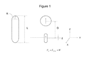
- the capsule endoscope is a basic three-dimensional geometric shape consisting of a cylinder with hemispherical ends. Said capsule has a length of L and a radius of R for the semi-sphere end.
- the capsule endoscope has a permanent magnetic dipole, positioned inside the cylinder portion of the capsule endoscope. Said magnetic dipole of capsule endoscope has a magnetic moment of m.
- the capsule endoscope may further comprise one or more image devices.
- the image device in one example is a camera.
- the camera may be positioned at the end of the capsule endoscope. When there are two cameras positioned on the capsule endoscope, preferably, the two cameras are position at opposite ends of the camera.
- the system further comprises an external magnetic, which is sphere shaped, having a magnetic moment M.
- Such a capsule endoscope suspended at the liquid/gas interface, is subjected to three forces, the gravity of capsule (W), the magnetic force (F m ) from the external magnetic field, and a floating force (F float ) from the liquid.
- the capsule In the stable suspension state, the capsule is supported by the floating force (F float ), and external magnetic field force (F m ).
- the weight of the capsule (W), floating force (F float ) and magnetic force (F m ) has the following relationship (Eq.1).
- F m + F float W
- F m ⁇ 0 4 ⁇ 6 Mm
- F float ⁇ liquid L / 2 + z ⁇ R 2
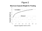
- Figure 2 sets up critical configuration limitation of the capsule endoscope in accordance with the aspects of the present invention.
- the magnetic moment (m) of the magnetic dipole in the capsule endoscope and the weight of the capsule endoscope have to meet the relationship requirement of Figure 2 in order to be able to a functional and useful suspended capsule endoscope system.
- the area underneath the curve is an allowed region and the area above the curve is a forbidden region.
- Figure 2 suggests that, in a system having an external magnet with a magnetic moment at 2000 (Am ⁇ 2), when the magnetic moments of the magnetic dipole inside capsule endoscope is between 0.01-0.6 (Am ⁇ 2), the weight of capsule need to be between 3-8 g in order to be suspended.
- Figure 2 depicts a weight limitation.
- the capsule magnetic moment when the capsule magnetic moment is at 0.1 (Am ⁇ 2), the weight of capsule needs to be fewer than 6 g, otherwise the capsule will be too heavy for suspension.
- the capsule magnetic moment is at 0.2(Am ⁇ 2)
- the weight of capsule needs to be fewer than 6.2 g; otherwise the capsule will be too heavy for suspension.
- the weight of capsule when the capsule magnetic moment is at 0.3 (Am ⁇ 2), the weight of capsule needs to be fewer than 7 g; otherwise the capsule will be too heavy for suspension. In another example, when the capsule magnetic moment is at 0.4 (Am ⁇ 2), the weight of capsule needs to be fewer than 7.5 g, otherwise the capsule will be heavy for suspension. In another example, when the capsule magnetic moment is at 0.5 (Am ⁇ 2), the weight of capsule needs to be fewer than 7.8 g; otherwise the capsule will be too heavy for suspension. In another example, when the capsule magnetic moment is at 0.6 (Am ⁇ 2), the weight of capsule needs to be fewer than 8 g; otherwise the capsule will be too heavy for suspension.
- Figure 2 suggests a limitation of the corresponding strength of the magnetic dipole in the capsule endoscope.
- the magnetic moment of the capsule endoscope needs to be greater than 0.05 (Am ⁇ 2).
- the magnetic moment of the capsule endoscope needs to be greater than 0.15 (Am ⁇ 2).
- the weight target for a capsule is about 7 g
- the magnetic moment of the capsule endoscope needs to be greater than 0.3 (Am ⁇ 2).
- the weight target of a capsule is 8 g, the magnetic moment of the capsule endoscope needs to be greater than 0.55 (A/cm ⁇ 2).
- Equations 1-5 and Figures 1 and 2 suggests how to change the capsule weights or magnetic moments under different circumstances, in order to achieve a stable system. But the aforementioned example should be construed as a limitation. Instead, Equations 1-5 can also be used to design a system that having a capsule endoscope having a fixed weight and magnetic moment, the external magnet can be changed under different circumstance. Like for example, in a portable system, wherein the external magnet is a hand held device, although it may not be a preferred application of the present invention.
- the present invention is directed to a magnetic endoscope system having an external robotic magnet, wherein the capsule endoscope can be suspended in a liquid in a vivo area, the density of the capsule endoscope is greater than the density of the liquid therein.
- the capsule endoscope Without the applied force (F m ) from the external robotic magnet, the capsule will not be able to suspend or float in the liquid. In another words, the capsule endoscope only moves in response to the movement of the external magnet.
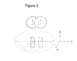
- the magnet capsule endoscope follows the external magnetic to navigate in a XY plane. When the external magnet performs a translation, the magnetic capsule does the same in response to the magnetic field force.
- the magnetic endoscope travels in the same direction of the movement of the external robotic magnet.
- the capsule endoscope also moves to the right.
- the capsule endoscope also moves to the front, which is illustrated as X direction.
- the external magnet performs a translation, the magnetic capsule does the same to follow the magnetic field force.
- the magnet capsule endoscope can also moves vertically, along a namely z direction as illustrated in Figure 4 .
- a patient lies flat on a surface along the XY plane and a capsule endoscope is placed inside the stomach of the patient.
- the capsule endoscope is suspended in the liquid or at liquid /air interface.
- the external robotic magnet moves up and down vertically, capsule endoscope moves vertically too in response to the change of location of the external robotic magnet.
- Figure 4 illustrates the magnetic capsule endoscope moves in the opposite direction of movement of the external robotic magnet.
- the capsule endoscope When the external robotic magnet moves down, it bring the external magnetic field closer to the magnetic dipole in the capsule endoscope, the capsule endoscope is attracted to move up. When the external robotic magnet moves up, it moves away from the magnetic capsule endoscope, the magnetic field weaken as the external magnetic moves up, and the capsule endoscope moves down.
- the capsule's position along z direction can be precisely controlled.
- the capsule When examining a stomach, the capsule can be conveniently positioned to first have a remote view followed by a closer view of the gastric mucosa for the top or bottom wall of thereof.
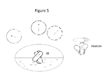
- the magnetic capsule endoscope can also perform rotational movements, including tilts and revolutions under the influence of the external magnetic field generated by the external robotic magnet.
- tilts and revolutions are necessary for the doctor to examine a broader view of the stomach while being suspended as anchored in an elevated position.
- Figure 5 shows the difference between a tilt and revolution movement.
- the capsule endoscope in the present invention When the capsule endoscope in the present invention is suspended at a liquid/gas interface, the capsule forms an angle with the liquid/gas interface. Said angles are referred as a tilt angle.
- the tilt angle is between 0-360 degrees in accordance with the present invention. In one example, said tilt angle is between 45-135 degrees to allow easy and accurate orientation.
- rotation or rotation movements mean the magnetic capsule endoscope changes its orientation in either a 2D plane or a 3D space.
- Rotation or rotational movements include both a tilt, changing the angle between the capsule and gas/liquid interface in a 2D plane, and a revolution, changing the angle between the capsule and gas/liquid interface in a 3D space, wherein the position of the capsule endoscope at the liquid/gas interface is not changed during the movement process, but the tilt angle or the tilt angle in a 2D cross sectional view of the revolution is changed before and after the rotation.
- rotational movement is a tilt.
- Tilt occurs in a plane of z axis and the vertical rotational magnetic moment of the sphere shaped magnet, as shown in Figure 5 , wherein the capsule changes its tilt angle like a hand in a clock.
- rotation movement is a revolution.
- Revolution occurs in a xyz space, wherein the capsule endoscope revolves around its anchor position at the liquid/gas interface as shown in Figure 5 .
- the capsule endoscope revolves according to the horizontal projection in xy-plane of the magnetic moment of the sphere shaped external magnet.
- the angle between the long axis of the capsule endoscope and the surface of the liquid and air interface is kept the same during the revolution.
- the projection of the angle formed between the long axis of the capsule and liquid/gas interface changes in accordance with the movement of the external magnet.
- tilt means the capsule endoscope does not changes its position in the xyz coordinates, but just change the angle between the capsule's long axis and the gravity direction, which is perpendicular to the air/liquid interface.
- revolution means the capsule endoscope also does not change its position in the xyz coordinates, but changes the direction of the capsule's long axis along liquid/gas interface, which results in a change of tilt angle in its corresponding 2D cross sectional view.
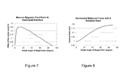
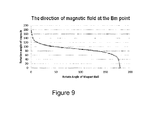
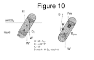
- the external magnet would have to 1) translate while rotate to keep the capsule endoscope still ( Figures 6 and 7 ); 2) to move closer to the liquid/gas interface in order to compensate the weakening of the magnetic field due to the rotation, in order to apply constant magnetic filed force to the capsule during the rotation ( Figure 8 ); and 3 ) to perform rotations between 45-135 degrees when the direction of external magnet field remains relatively small, so that the capsule endoscope will change its tilt angle by following the rotation of the external magnet ( Figure 9 ); or alternatively, 4) changing the tilt angle of the capsule endoscope by changing the direction of the magnetic filed as long as the mass center and magnetic center of the capsule is less than 2mm ( Figure 10 ).
- the external robotic magnet In order to rotate a capsule endoscope to change ONLY its tilt angle, while still maintaining its position, the external robotic magnet in a spherical shape, would have to rotate and translate at the same time. If the external magnet only rotates, the rotational magnetic field generated by the external robotic magnet will not only rotate the capsule endoscope as intended, but also move capsule endoscope in one or both xy coordinates unintentionally, i.e. change the position of the capsule endoscope at the liquid/gas interface, because the maximum magnetic filed on the liquid/gas interface has been altered from one position to another in response to the rotational magnetic field, and the capsule endoscope bearing a permanent magnetic dipole is being attracted to the second maximum magnetic field position in the liquid/gas interface.
- the capsule when the external robotic magnetic rotates, the capsule also rotate to change its tilt angle at the liquid/gas interface. At the same time when the rotation occurs, the capsule endoscope moves horizontally from X 0 to X 1 .
- the dashed ellipse is the equal magnetic field line
- the tangential point at the gas/liquid interface is the maximum magnetic field point Bm
- the distance from X 0 to X 1 is the referred as the offset distance t in Figure 7.
- Figure 7 plots a relationship between the rotation angle of the external magnet (degrees) and the undesired movement of the capsule in a normalized x/d format, wherein d is the distance from the center of external magnet to the liquid/gas interface and x is horizontal distance between the magnet center of the capsule endoscope to the projection point of the center of external magnet at the liquid/gas interface, which is the same distance from X 0 to X 1 .
- d is the distance from the center of external magnet to the liquid/gas interface
- x is horizontal distance between the magnet center of the capsule endoscope to the projection point of the center of external magnet at the liquid/gas interface, which is the same distance from X 0 to X 1 .
- Figure 3 shows that capsule endoscope moves in the x or y direction by following the external magnet.
- the external magnet in the present invention will also move in the x or y direction to offset.
- the direction of the movement of the external magnet will be in the opposite direction of the undesired capsule movement and the distance of movement of the external magnet will be calculated based on the distance of the undesired movement of the capsule endoscope.
- the translation can happen during the rotation or before/ after the rotation.
- the external magnet rotates and performs a translation at the same time.
- a method to maintain a capsule endoscope at the same position while it rotates, wherein the capsule endoscope is suspended at liquid/gas interface having a first tilt angle includes providing a capsule endoscope comprising a permanent magnetic dipole and a camera; suspending the capsule endoscope at a liquid/gas interface, wherein the capsule endoscope forms a tilt angle at a liquid/gas interface to observe an internal organ; applying magnetic field force to the permanent magnet dipole through an external magnet; changing the angle of the tilt angle while being suspended at the same at the same position at the liquid/gas interface by rotating and moving the external magnet along one or more axially directions.
- a method to apply constant magnet field force to a capsule endoscope while it rotates, wherein the capsule endoscope is suspended at liquid/gas interface having a first tilt angle includes providing a capsule endoscope comprising a permanent magnetic dipole and a camera; suspending the capsule endoscope at a liquid/gas interface, wherein the capsule endoscope forms a tilt angle at a liquid/gas interface to observe an internal organ; applying magnetic field force to the permanent magnet dipole through an external magnet; and changing the tilt angle of the capsule endoscope while being suspended at the liquid/gas interface by rotating the external magnet; and adjusting the distance between the external magnet and liquid gas interface to apply constant external magnet field force to the capsule endoscope during the rotation.
- the y-axis is the field angle (direction) of the external magnetic field at the position of the maximum magnetic field in the gas/liquid interface.
- the capsule will follow the external magnetic field direction.
- the capsule endoscope tilt angle will change correspondingly.
- Figure 9 suggests this angle control is relative easier to if the rotation angle of the capsule between 45 degree and 135 degree.
- the distance between the magnetic center of capsule and the mass center of the capsule is very small, changing the direction of the external magnetic field can change the tilt angle of the capsule endoscope.
- the distance between the magnetic center of capsule and the mass center of the capsule is less than 2 mm.
- Said magnetic center of the capsule is the center of small magnetic dipole inside the capsule endoscope.
- F float is the floating force
- W is the gravity of the capsule
- W' is the effective weight of the capsule suspended in the liquid, which is water in this example.
- D 1 is the horizontal distance from the gravity center (mass center) of the liquid occupied or replaced by the part of the capsule to the effective capsule weight center; and D 2 is the horizontal distance from the gravity center (mass center) of the liquid occupied by the part of the capsule to the capsule mass center.
- F m is magnetic field force on the small magnetic dipole in capsule; B is the magnetic field with the ⁇ angle to the horizontal plane, the m is the magnetic moment of the small magnetic dipole inside the capsule.
- the D dm is the distance between the center of small magnet d ipole in the capsule and the effective weight center ( m ass center) of the capsule.
- the ⁇ is the additional tilt angle for the line connecting the small magnet and the effective weight center.
- the D dm should be small, so it is preferred to make the small magnet to be close to the mass center of the capsule, e.g. ⁇ 2mm.
- the capsule endoscope has one camera, the distance between the small magnetic dipole and mass center is less than 2 mm.
- the capsule endoscope has a length of L, and its length is longer than 12 mm when the capsule has two cameras, one on each end of the capsule.
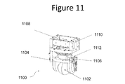
- Figure 11 shows an exemplary external robotic magnet in accordance with the aspects of the present invention, which provides a sphere-shaped external magnet, allowing translation, vertically movement, horizontal and vertical rotation.
Abstract
Description
- The invention relates to medical apparatus and instruments, specifically refers to a system and method to control movement of a capsule endoscope in a human GI track.
- With the development of large-scale integrated circuit technology, MEMS, wireless communications and optical technology, capsule endoscope has been used as an effective way for diagnosis for intestinal diseases. M2A produced by Given Imaging, a company in Israel, Endo Capsule researched and developed by Olympus Company in Japan, and products marketed under a Chinese company, Jinshan Science and Technology, all have taken significant market shares in the capsule endoscope marketplace. The current available wireless capsules adopted in the medical field are carried by peristalsis through a human digestive tract, as a result the movement speed, movement direction and capsule location is random, which makes it difficult for medical doctors to collect the relevant information for intestinal tract diagnosis.
- If positioning and controlling a capsule endoscope in vivo cannot be achieved, navigating it through a human GI track for traversal intestinal diagnosis/examination face multiple issues. Current existing capsule endoscopes mainly rely on peristalsis and organs contraction to accomplish the capsule movement along a GI track in vivo. Such movement is not only slow, leading to low detection efficiency and potential dead zones in the examination, but also makes examination or operation in specific disease region impossible, as the movement based on peristalsis cannot move the capsule endoscope back and forth to a precise target location for a stable examination or operation, and such movement does not allow control of movement speed and direction, and the posture.
- Chinese domestic Jinshan Group has manually controlled an external magnet to accomplish the position or navigation of a capsule endoscope in GI track. The manual control is low cost, but is less precise than a mechanical robot thus less favorable in a routine testing, which prefers artificial intelligence. Furthermore, several scientific research institutions have demonstrated controlling a magnetic capsule endoscope by a strip shaped external magnet. This method is quick and can precisely place the capsule in a direct route, however, because human GI track is not straight but very snaky, it is very difficult to carry out actual positioning of capsule endoscope using such linear magnet in practical clinical setting.
- US patent applications
US20070221233 ,US20100268026 ,US20110054255 , andUS20110184235 disclosed a floating or suspended capsule. As described in these patent applications, a magnetic capsule is suspended by a surrounding liquid, which requires the density of the capsule to be less than the liquid. In clinical practice, since the most commonly used liquid is water, the weight of such floated capsule is limited to be under 3g. If a capsule is equipped with a permanent magnetic dipole to achieve better positioning, the weight of the capsule unfortunately easily go over 3g. For a capsule endoscope whose density is more than water and perhaps weight is over 3g, how to realize stable suspension has not been disclosed. - The present invention overcomes the technology difficulties in the prior arts, and provides a system and method to control the movement of a capsule endoscope in a human GI track. The system and method disclosed herein, is capable to precisely generate a 5-dimensional moving and rotational magnetic field, to remotely apply force to a magnetic capsule endoscope, which is suspended in a liquid gas interface.
- In a first aspect of the present invention, a capsule endoscope includes a capsule-shaped housing and an imaging unit that is arranged inside the capsule-shaped housing in a fixed manner, and takes an image of an inside of an organ by the imaging unit in a state where the capsule endoscope is suspended at a liquid/gas interface. The liquid and gas is introduced inside the organ of a subject. In one embodiment of the present invention, the capsule endoscope suspended at the liquid/gas interface comprises a permanent magnetic dipole, wherein the capsule endoscope has a mass center and the permanent magnetic dipole inside the capsule endoscope has a magnetic center. The capsule endoscope changes its position or orientation by interacting with an external magnetic.
- In one embodiment of the present invention, the density of capsule endoscope is greater than the density of the liquid. In another embodiment of the present invention, the mass of the capsule endoscope is greater than 3g.
- In another embodiment of the present invention, the distance between the magnetic center and mass center of capsule endoscope is less than 2 mm.
- In a second aspect of the present invention, a method to use a capsule endoscope having a permanent magnetic dipole is disclosed. The method comprises a step to rotate the capsule endoscope locally when the capsule endoscope forms a tilt angle at a liquid/gas interface to observe an internal organ. The method comprises providing a capsule endoscope comprising a permanent magnetic dipole and a camera;
suspending the capsule endoscope at the liquid/gas interface; applying magnetic field to the permanent magnet dipole through an external magnet;
changing the tilt angle of the capsule endoscope while being suspended at the same position at the liquid/gas interface by rotating and moving the external magnet along one or more axially directions; and
receiving constant magnetic field force by the permanent magnetic dipole. - The above and other features, advantages and technical and industrial significance of this invention will be better understood by reading the following detailed description of presently preferred embodiments of the invention, when considered in connection with the accompanying drawings.
-
-
FIG. 1 is a schematic diagram showing an example of a capsule endoscope according to one aspect of the present invention; -
FIG. 2 is a relationship between a capsule weight and capsule magnetic moment, explaining the maximum allowable weight for the capsule endoscope in order to achieve stable suspension, in accordance with one aspect of the present invention; -
FIG. 3 is a schematic illustration of a cross section view the system disclosed herein, wherein the capsule endoscope moves horizontally in response to a horizontal movement of an external magnetic; -
FIG. 4 is a schematic illustration of a cross section view of the system disclosed herein, wherein the capsule endoscope moves vertically in response to a vertical movement of the external magnetic; -
FIG. 5 is a schematic diagram of a cross section view of the system disclosed herein, to explain a desired rotational operation of the capsule endoscope inside an organ while being suspended at an gas/liquid interface, wherein combinational movements of the external magnet only change the tilt angles of the capsule leaving its position at the liquid/gas interface mostly unchanged; -
FIG. 6 is a schematic diagram of a cross section view of the system disclosed herein, explaining a simple rotation of the external magnet causes the capsule endoscope to move away from its original position, more than a simple rotation at its original position, when the capsule is being suspended at the gas/liquid interface; -
FIG. 7 is an illustration of the relationship between the vertical rotation angle of the magnetic moment of the external magnet and the undesired movement of the capsule endoscope (in a normalized value); -
FIG. 8 is an illustration of the relationship between the vertical rotation angle of the magnetic moment of the external magnet and the distance (in a normalized value) along a vertical direction to be adjusted in order to apply constant magnetic field force to the capsule endoscope; -
FIG. 9 plots a relationship between rotational angle of the capsule endoscope and the vertical rotation angle of the magnetic moment of the external sphere-shaped magnet; -
FIG. 10 is a schematic diagram to explain the various force experienced by a capsule endoscope while being suspended at a gas/liquid interface having a tilted angle in accordance with the aspect with the present invention; and -
FIG. 11 is an exemplary embodiment of an external robotic magnet, in accordance with the aspect of the present invention. - Exemplary embodiments of a capsule endoscope according to the present invention are explained in detail below with reference to the accompanying drawings. The present invention is not limited to the embodiments.
- Ingestible wireless medical capsules are known in the medical arts. Such wireless capsule is swallowed and travels through the digestive tract, collecting and transmitting data during the course of its journey, can also collecting images if equipped with cameras. When a capsule endoscope is equipped with a permanent magnetic dipole, the capsule endoscope can be parked at a target location for a desired period of examination.
- It is one object of the present invention to place a capsule endoscope in a precise location in a target area, which maybe a disease area, and collect real-time medical related information so that the medical doctors can easily perform diagnose or operation on that precise target location.
- Further when the capsule endoscope is positioned at the target location, the capsule endoscope needs to be fixed at the target location, substantially stable, for a specific period of time, in order to be collect accurate information or non blurred images. Stable, herein, refers to a status of the capsule, which can maintain its position and orientation without a change, or a detectable change, or a noticeable change can be ignored in a desired applicable experimental or clinical settings. The capsule endoscope, in accordance with the present invention, comprises a permanent magnetic dipole. The magnetic dipole is a vector. The location of a capsule endoscope as referred to in the present invention, includes its location with respect to a reference, and angles with respect to some reference. The orientation of a capsule endoscope includes its direction with respect to some reference. The target location, herein, include a liquid and gas, having a definable liquid/gas interface.
- In one embodiment, the capsule endoscope can be stable for at least the time duration for taking an image with an acceptable resolution or performing a simple test or procedure.
- Since various prior arts have provided multiple ways to navigate a capsule endoscope into a precise location, the system and methods, disclosed in the present invention, are mostly directed to how to use the external magnet to change the orientation of the capsule while it is being suspended in a stable state at a desired location.
- System disclosed herein comprises a capsule endoscope, which is placed in a target area, consisting essentially of a liquid and a gas. The capsule endoscope includes a capsule-shaped housing and an imaging unit that is arranged inside the capsule-shaped casing in a fixed manner, and takes an image of an inside of target area, by the imaging unit in a state where the capsule endoscope is suspended in a liquid/gas interface. In one embodiment of the present invention, the capsule endoscope suspended at the liquid/gas interface comprises a permanent magnetic dipole, wherein the capsule endoscope has a mass center and the permanent magnetic dipole has a magnetic center. The capsule endoscope changes its position or orientation by interacting with an external magnetic.
- In one example, the target area is an internal organ. In one instance, the target area is a stomach. In another example, stomach is partially filed with a liquid.
- In one example, the liquid and gas are introduced to the target area after the target area has been vacated. In one example, the liquid is water. In another example, gas is air. In still another example, gas is air with additional CO2, which is generated by oral acrogenic powder.
- The present invention is directed to a capsule endoscope being suspended at a liquid/gas interface. "Being suspended at a liquid/gas interface" does not suggest a limitation on the partition of the capsule in either the liquid or the gas phase. Within the scope of the present invention, as long as the capsule experienced a floating force from the liquid, then the capsule is considered to be as suspended, which includes the capsule is completely immersed and the capsule is mostly exposed, thought these examples are not the best modes to use the present invention.
- The capsule endoscope in the present invention has a housing. The capsule endoscope can be of any shape or in any size of a pill as in the general art. In one example, the capsule is cylindrical shaped with hemispherical ends, spherical, capsule shaped but with size of one end larger than the other end, or an American football shaped. The capsule endoscope in the present invention is preferred to be symmetrical along its length direction. The capsule endoscope has a mass center, which is the weight center when measured in the air, inherit with the structure of the capsule endoscope and cannot be changed because of the environment it is placed in. The capsule endoscope comprises a permanent magnetic dipole, which also has a center of magnetic moment, which is referred as a center of the magnetic dipole.
- The capsule endoscope disclosed herein, has a density, which is an inherit property of the capsule due to the material and structural components and does not change because of the environment it is placed in. Unlike most of floating capsule endoscopes disclosed in the prior arts, which requires a density to be less than the density of the liquid, normally 1, the density of the capsule endoscope of the present invention is required to be more than the liquid density, in order to be successfully and accurately suspended at a target location.
- System disclosed herein comprises an external magnet, generating an external magnetic field, 5-dimensional moving and rotational magnetic field, to remotely apply force to a magnetic capsule endoscope.
- Referring to
Figure 1 , a capsule endoscope in a stable suspension state is schematically illustrated. In this example, as shown, the capsule endoscope is a basic three-dimensional geometric shape consisting of a cylinder with hemispherical ends. Said capsule has a length of L and a radius of R for the semi-sphere end. The capsule endoscope has a permanent magnetic dipole, positioned inside the cylinder portion of the capsule endoscope. Said magnetic dipole of capsule endoscope has a magnetic moment of m. The capsule endoscope may further comprise one or more image devices. The image device, in one example is a camera. The camera may be positioned at the end of the capsule endoscope. When there are two cameras positioned on the capsule endoscope, preferably, the two cameras are position at opposite ends of the camera. The system further comprises an external magnetic, which is sphere shaped, having a magnetic moment M. - Such a capsule endoscope, suspended at the liquid/gas interface, is subjected to three forces, the gravity of capsule (W), the magnetic force (Fm) from the external magnetic field, and a floating force (Ffloat) from the liquid. In the stable suspension state, the capsule is supported by the floating force (Ffloat), and external magnetic field force (Fm). The weight of the capsule (W), floating force (Ffloat) and magnetic force (Fm) has the following relationship (Eq.1).


- Further, under the same condition, floating force (Ffloat) and external magnetic filed force (Fm) are established as in
equations 2 and 3. Wherein M is the magnet moment of the external magnet in the system, m is the magnetic moment of the magnetic dipole in the magnetic capsule. D is the vertical distance from the magnetic center of the external magnet dipole to the magnetic center of the magnetic capsule; z is the vertical distance between the liquid-air interface and the magnetic center of the capsule as inFigure 1 . - When stable suspension is established, the following conditions (Eq. 4 and Eq.5) are met.


- Therefore, the maximum capsule weight allowed (W) in order to achieve a stable suspension can be derived based on Equations 1-5.
Figure 2 sets up critical configuration limitation of the capsule endoscope in accordance with the aspects of the present invention. The magnetic moment (m) of the magnetic dipole in the capsule endoscope and the weight of the capsule endoscope have to meet the relationship requirement ofFigure 2 in order to be able to a functional and useful suspended capsule endoscope system. InFigure 2 , the area underneath the curve is an allowed region and the area above the curve is a forbidden region.Figure 2 suggests that, in a system having an external magnet with a magnetic moment at 2000 (Am^2), when the magnetic moments of the magnetic dipole inside capsule endoscope is between 0.01-0.6 (Am^2), the weight of capsule need to be between 3-8 g in order to be suspended. In one perspective to design a capsule endoscope having a known and fixed magnetic moment,Figure 2 depicts a weight limitation. In another words, in one example, when the capsule magnetic moment is at 0.1 (Am^2), the weight of capsule needs to be fewer than 6 g, otherwise the capsule will be too heavy for suspension. In another example, when the capsule magnetic moment is at 0.2(Am^2), the weight of capsule needs to be fewer than 6.2 g; otherwise the capsule will be too heavy for suspension. In another example, when the capsule magnetic moment is at 0.3 (Am^2), the weight of capsule needs to be fewer than 7 g; otherwise the capsule will be too heavy for suspension. In another example, when the capsule magnetic moment is at 0.4 (Am^2), the weight of capsule needs to be fewer than 7.5 g, otherwise the capsule will be heavy for suspension. In another example, when the capsule magnetic moment is at 0.5 (Am^2), the weight of capsule needs to be fewer than 7.8 g; otherwise the capsule will be too heavy for suspension. In another example, when the capsule magnetic moment is at 0.6 (Am^2), the weight of capsule needs to be fewer than 8 g; otherwise the capsule will be too heavy for suspension. - On the other hand, in some uncommon examples, when configuring a capsule endoscope to have a desired weight or a weight range,
Figure 2 suggests a limitation of the corresponding strength of the magnetic dipole in the capsule endoscope. In one example, when the weight target of a capsule is about 5 g, the magnetic moment of the capsule endoscope needs to be greater than 0.05 (Am^2). In another example, when the weight target for a capsule is about 6 g, the magnetic moment of the capsule endoscope needs to be greater than 0.15 (Am^2). In another example, when the weight target for a capsule is about 7 g, the magnetic moment of the capsule endoscope needs to be greater than 0.3 (Am^2). In another example, when the weight target of a capsule is 8 g, the magnetic moment of the capsule endoscope needs to be greater than 0.55 (A/cm^2). - In the aforementioned examples, it is disclosed a stationary system, wherein the external magnet is stationed with robotic arms with a magnetic moment. Equations 1-5 and
Figures 1 and2 , suggests how to change the capsule weights or magnetic moments under different circumstances, in order to achieve a stable system. But the aforementioned example should be construed as a limitation. Instead, Equations 1-5 can also be used to design a system that having a capsule endoscope having a fixed weight and magnetic moment, the external magnet can be changed under different circumstance. Like for example, in a portable system, wherein the external magnet is a hand held device, although it may not be a preferred application of the present invention. - Referring to
Figures 3 and4 , the present invention is directed to a magnetic endoscope system having an external robotic magnet, wherein the capsule endoscope can be suspended in a liquid in a vivo area, the density of the capsule endoscope is greater than the density of the liquid therein. Without the applied force (Fm) from the external robotic magnet, the capsule will not be able to suspend or float in the liquid. In another words, the capsule endoscope only moves in response to the movement of the external magnet. As shown inFigure 1 , the magnet capsule endoscope follows the external magnetic to navigate in a XY plane. When the external magnet performs a translation, the magnetic capsule does the same in response to the magnetic field force. In the XY plane, the magnetic endoscope travels in the same direction of the movement of the external robotic magnet. When the external robotic magnet moves to the right, the capsule endoscope also moves to the right. When the external robotic magnet moves to the front, the capsule endoscope also moves to the front, which is illustrated as X direction. When the external magnet performs a translation, the magnetic capsule does the same to follow the magnetic field force. - The magnet capsule endoscope can also moves vertically, along a namely z direction as illustrated in
Figure 4 . In one embodiment of the present invention, a patient lies flat on a surface along the XY plane and a capsule endoscope is placed inside the stomach of the patient. The capsule endoscope is suspended in the liquid or at liquid /air interface. When the external robotic magnet moves up and down vertically, capsule endoscope moves vertically too in response to the change of location of the external robotic magnet. Contrary to the movement path illustratedFigure 3 wherein the capsule endoscope moves in the same direction of the external robotic magnet,Figure 4 illustrates the magnetic capsule endoscope moves in the opposite direction of movement of the external robotic magnet. When the external robotic magnet moves down, it bring the external magnetic field closer to the magnetic dipole in the capsule endoscope, the capsule endoscope is attracted to move up. When the external robotic magnet moves up, it moves away from the magnetic capsule endoscope, the magnetic field weaken as the external magnetic moves up, and the capsule endoscope moves down. By controlling the movement of the external robotic magnet along the vertical or z direction, the capsule's position along z direction can be precisely controlled. When examining a stomach, the capsule can be conveniently positioned to first have a remote view followed by a closer view of the gastric mucosa for the top or bottom wall of thereof. - Besides translation along three axes as shown in
Figures 3-4 , the magnetic capsule endoscope can also perform rotational movements, including tilts and revolutions under the influence of the external magnetic field generated by the external robotic magnet. In a clinical environment, tilts and revolutions are necessary for the doctor to examine a broader view of the stomach while being suspended as anchored in an elevated position.Figure 5 shows the difference between a tilt and revolution movement. - When the capsule endoscope in the present invention is suspended at a liquid/gas interface, the capsule forms an angle with the liquid/gas interface. Said angles are referred as a tilt angle. The tilt angle is between 0-360 degrees in accordance with the present invention. In one example, said tilt angle is between 45-135 degrees to allow easy and accurate orientation.
- In accordance with the aspects with the present invention, rotation or rotation movements mean the magnetic capsule endoscope changes its orientation in either a 2D plane or a 3D space. Rotation or rotational movements include both a tilt, changing the angle between the capsule and gas/liquid interface in a 2D plane, and a revolution, changing the angle between the capsule and gas/liquid interface in a 3D space, wherein the position of the capsule endoscope at the liquid/gas interface is not changed during the movement process, but the tilt angle or the tilt angle in a 2D cross sectional view of the revolution is changed before and after the rotation. In one embodiment, rotational movement is a tilt. Tilt occurs in a plane of z axis and the vertical rotational magnetic moment of the sphere shaped magnet, as shown in
Figure 5 , wherein the capsule changes its tilt angle like a hand in a clock. In another embodiment, rotation movement is a revolution. Revolution occurs in a xyz space, wherein the capsule endoscope revolves around its anchor position at the liquid/gas interface as shown inFigure 5 . While the capsule endoscope revolves according to the horizontal projection in xy-plane of the magnetic moment of the sphere shaped external magnet. InFigure 5 , the angle between the long axis of the capsule endoscope and the surface of the liquid and air interface is kept the same during the revolution. In a cross sectional view of a revolution, the projection of the angle formed between the long axis of the capsule and liquid/gas interface changes in accordance with the movement of the external magnet. - For clarify purpose, tilt means the capsule endoscope does not changes its position in the xyz coordinates, but just change the angle between the capsule's long axis and the gravity direction, which is perpendicular to the air/liquid interface. In accordance with the aspects with the present invention, revolution means the capsule endoscope also does not change its position in the xyz coordinates, but changes the direction of the capsule's long axis along liquid/gas interface, which results in a change of tilt angle in its corresponding 2D cross sectional view.
- Unlike the translation movement, wherein a one-step operation of the external robotic magnet can help to navigate the capsule endoscope into a target location; rotational movement is a more complicated process. When the external robotic magnet rotates, an established stable suspension system will be perturbed in many aspects. The maximum magnetic field position at the liquid/gas interface, the external magnetic filed strength at the liquid/gas interface, and the external magnetic field direction (or angle) will all change. The external magnet would have to 1) translate while rotate to keep the capsule endoscope still (
Figures 6 and7 ); 2) to move closer to the liquid/gas interface in order to compensate the weakening of the magnetic field due to the rotation, in order to apply constant magnetic filed force to the capsule during the rotation (Figure 8 ); and3 ) to perform rotations between 45-135 degrees when the direction of external magnet field remains relatively small, so that the capsule endoscope will change its tilt angle by following the rotation of the external magnet (Figure 9 ); or alternatively, 4) changing the tilt angle of the capsule endoscope by changing the direction of the magnetic filed as long as the mass center and magnetic center of the capsule is less than 2mm (Figure 10 ). - In order to rotate a capsule endoscope to change ONLY its tilt angle, while still maintaining its position, the external robotic magnet in a spherical shape, would have to rotate and translate at the same time. If the external magnet only rotates, the rotational magnetic field generated by the external robotic magnet will not only rotate the capsule endoscope as intended, but also move capsule endoscope in one or both xy coordinates unintentionally, i.e. change the position of the capsule endoscope at the liquid/gas interface, because the maximum magnetic filed on the liquid/gas interface has been altered from one position to another in response to the rotational magnetic field, and the capsule endoscope bearing a permanent magnetic dipole is being attracted to the second maximum magnetic field position in the liquid/gas interface. For example, as shown in
Figure 6 , when the external robotic magnetic rotates, the capsule also rotate to change its tilt angle at the liquid/gas interface. At the same time when the rotation occurs, the capsule endoscope moves horizontally from X0 to X1. InFigure 6 , the dashed ellipse is the equal magnetic field line, the tangential point at the gas/liquid interface is the maximum magnetic field point Bm, and the distance from X0 to X1 is the referred as the offset distance t inFigure 7. Figure 7 plots a relationship between the rotation angle of the external magnet (degrees) and the undesired movement of the capsule in a normalized x/d format, wherein d is the distance from the center of external magnet to the liquid/gas interface and x is horizontal distance between the magnet center of the capsule endoscope to the projection point of the center of external magnet at the liquid/gas interface, which is the same distance from X0 to X1. According toFigure 7 , when the external magnet in a sphere shape rotates about 10 degrees, the capsule endoscope will move horizontally at a value of x/d at 0.25, which suggests when a distance d is of 30 cm and the capsule endoscope moves to 7.5 cm unintentionally. - However, such unintentional movement in either x or y coordinates is not desired and hence minimized by the method disclosed herein.
Figure 3 shows that capsule endoscope moves in the x or y direction by following the external magnet. In order to the avoid the undesired movement of the capsule endoscope as a result of the rotation of external magnet, the external magnet in the present invention will also move in the x or y direction to offset. The direction of the movement of the external magnet will be in the opposite direction of the undesired capsule movement and the distance of movement of the external magnet will be calculated based on the distance of the undesired movement of the capsule endoscope. In the same selected example inFigure 7 , when the distance d is of 30 cm, and the external magnet rotates 10 degrees, the anticipated 7.5 cm movement to the left of the capsule will be corrected by translating the external magnet further to the right at 7.5cm, which is equivalent to move the capsule endoscope 7.5 cm to the right. In the control of the suspended capsule, it is directly under the sphere-shaped external magnet when the magnetic moment of the magnet is parallel to the earth, thus it is perpendicular to the liquid/gas interface. When the sphere-shaped external magnet tilts along a horizontal angle, the capsule will exactly follow that the horizontal angle. The plane of line of the capsule's axis and the line of sphere-shaped external magnet magnetization is shown inFigure 5 . The plane is rotating symmetrically. So if we express the compensating translation movement in x,y plane, then

wherein X0,Y0 is the original position of the sphere-shaped external magnet; X,Y is the final position of the sphere-shaped external magnet. a is the horizontal rotation angle, t is the shift distance as shown inFigure 5 . - The translation can happen during the rotation or before/ after the rotation. Preferably the external magnet rotates and performs a translation at the same time.
- In one embodiment of the present invention, it is disclosed a method to maintain a capsule endoscope at the same position while it rotates, wherein the capsule endoscope is suspended at liquid/gas interface having a first tilt angle. The method includes
providing a capsule endoscope comprising a permanent magnetic dipole and a camera;
suspending the capsule endoscope at a liquid/gas interface, wherein the capsule endoscope forms a tilt angle at a liquid/gas interface to observe an internal organ;
applying magnetic field force to the permanent magnet dipole through an external magnet;
changing the angle of the tilt angle while being suspended at the same at the same position at the liquid/gas interface by rotating and moving the external magnet along one or more axially directions. - Further besides maintaining the capsule endoscope at the same position during the translation, it is also desired to subject the capsule endoscope to the same magnetic field force during the rotation process in order to achieve a smooth rotation. When the external magnet rotates, the magnetic field force experienced by the capsule endoscope changes. In order to apply constant magnetic filed force to the capsule endoscope, the distance between the external magnet and magnet capsule need to be changed. The calculation is shown in
Fig.8. Figure 8 plots a calculation of a distance that the external magnet ball needs to be moved relating to its rotational angle. For example, in a system that the distance d from the center of the sphere shaped external magnet to the gas/liquid interface before the rotation is 30 cm, and when the external magnet intends to rotate 90 degrees, then the external magnet needs to be adjusted along its vertical position to achieve a d/z value at 1.18, which means after the rotation the external magnet is at a position wherein z=d/1.18=30/1.18=25.4cm. This calculation further suggests that external magnet needs to be brought closer to the liquid/air interface for 30-25.4=4.6 cm. - In another embodiment of the present invention, it is disclosed a method to apply constant magnet field force to a capsule endoscope while it rotates, wherein the capsule endoscope is suspended at liquid/gas interface having a first tilt angle. The method includes
providing a capsule endoscope comprising a permanent magnetic dipole and a camera;
suspending the capsule endoscope at a liquid/gas interface, wherein the capsule endoscope forms a tilt angle at a liquid/gas interface to observe an internal organ;
applying magnetic field force to the permanent magnet dipole through an external magnet; and
changing the tilt angle of the capsule endoscope while being suspended at the liquid/gas interface by rotating the external magnet;
and adjusting the distance between the external magnet and liquid gas interface to apply constant external magnet field force to the capsule endoscope during the rotation. - Referring to
Figure 9 , during the rotation of the external magnet, its magnetic filed direction could also change depending on the rotation angle. InFigure 9 , the y-axis is the field angle (direction) of the external magnetic field at the position of the maximum magnetic field in the gas/liquid interface. When the magnetic field is strong or the capsule weight center and the small magnet dipole center is close, the capsule will follow the external magnetic field direction. By rotating sphere-shaped external magnet, the capsule endoscope tilt angle will change correspondingly.Figure 9 suggests this angle control is relative easier to if the rotation angle of the capsule between 45 degree and 135 degree. - However sometimes in the clinical settings, maneuver the capsule endoscope through a wide range and accomplish a more horizontal tilt removes the need to reposition the capsule endoscope and allows a quicker and efficient procedure.
- In an alternative embodiment of the present invention, if the distance between the magnetic center of capsule and the mass center of the capsule is very small, changing the direction of the external magnetic field can change the tilt angle of the capsule endoscope. In one example, the distance between the magnetic center of capsule and the mass center of the capsule is less than 2 mm. Said magnetic center of the capsule is the center of small magnetic dipole inside the capsule endoscope.
- Referring to
Figure 10 , the capsule being suspended experiences three forces, Ffloat is the floating force, (W) is the gravity of the capsule and W' is the effective weight of the capsule suspended in the liquid, which is water in this example. D1 is the horizontal distance from the gravity center (mass center) of the liquid occupied or replaced by the part of the capsule to the effective capsule weight center; and D2 is the horizontal distance from the gravity center (mass center) of the liquid occupied by the part of the capsule to the capsule mass center. Further, Fm is magnetic field force on the small magnetic dipole in capsule; B is the magnetic field with the β angle to the horizontal plane, the m is the magnetic moment of the small magnetic dipole inside the capsule. The Ddm is the distance between the center of small magnet dipole in the capsule and the effective weight center (mass center) of the capsule. The θ is the additional tilt angle for the line connecting the small magnet and the effective weight center. In a suspension state, the following equations are established (Equations 6-9).


- It can be derived from the above equations that by changing the direction of external field B, one can control the tilt angle of the floating capsules. Although the effective weight center is changing with immersion volume of capsule, it is still around the mass center. In order to easily control the tilt angle, the Ddm should be small, so it is preferred to make the small magnet to be close to the mass center of the capsule, e.g. <2mm. In one preferred example, when the capsule endoscope has one camera, the distance between the small magnetic dipole and mass center is less than 2 mm. In alternative preferred example, the capsule endoscope has a length of L, and its length is longer than 12 mm when the capsule has two cameras, one on each end of the capsule.
-
Figure 11 , shows an exemplary external robotic magnet in accordance with the aspects of the present invention, which provides a sphere-shaped external magnet, allowing translation, vertically movement, horizontal and vertical rotation. - Additional embodiments and modifications will readily occur to those skilled in the art. Therefore, the invention in its broader aspects is not limited to the specific details and representative embodiments shown and described herein. Accordingly, various modifications may be made without departing from the spirit or scope of the general inventive concept as defined by the appended claims and their equivalents.
Claims (17)
- A capsule endoscope system, comprising
a capsule endoscope suspended in a liquid environment having a liquid/gas interface, comprisinga permanent magnetic dipole, wherein the capsule endoscope has a mass center and the permanent magnetic dipole has a magnetic center; andan external magnetic field, interacting with the permanent magnetic dipole inside the capsule endoscope to position and orient the capsule endoscope at the gas/liquid interface;
wherein the density of capsule endoscope is larger than the density of the liquid. - The capsule endoscope of claim 1, wherein the mass of the capsule endoscope is larger than 3g.
- The capsule endoscope of any of the preceding claims, wherein a magnetic moment of the permanent magnetic dipole inside the capsule endoscope is between 0.001-0.6 Am2,
- The capsule endoscope of any of the preceding claims, wherein a mass of the capsule endoscope is between 3-8 g.
- The capsule endoscope of any of the preceding claims, wherein the magnetic moment of the external magnetic field is at 2000 Am2.
- The capsule endoscope of any of the preceding claims, wherein the distance between the magnetic center and mass center is less than 2 mm.
- The capsule endoscope of any of the preceding claims, wherein the line connecting the magnetic center and mass center is not perpendicular to the gas/liquid interface.
- The capsule endoscope of any of the preceding claims, wherein the capsule has a length of L and L is longer than 12 mm.
- The capsule endoscope of claim 6, wherein the capsule endoscope has only one camera.
- The capsule endoscope of claim 8, wherein the capsule endoscope has two cameras.
- A method to move a capsule endoscope locally, comprising
providing a capsule endoscope comprising a permanent magnetic dipole and a camera;
suspending the capsule endoscope at a liquid/gas interface, wherein the capsule endoscope forms a title angle at a liquid/gas interface to observe an internal organ; and
applying magnetic field force to the permanent magnet dipole through an external magnet to move the capsule endoscope;
wherein the capsule has a density greater than the density of the liquid. - The method of claim 11, further comprising
rotating the capsule endoscope while being suspended at the same position at the liquid/gas interface by rotating and moving the external magnet along one or more axially directions simultaneously. - The method of claim 12, the step of changing the tilt angle of the capsule endoscope while suspending the same at the same position at the liquid/gas interface, further comprises
moving the external magnet to the opposite direction to offset the movement of the capsule endoscope along an axially direction. - The method of claim 11, further comprising changing the tilt angle of the capsule endoscope by rotating the external magnet between 45-135 degrees.
- The method of claim 11, further comprising receiving constant magnetic field force by the permanent magnetic dipole inside the capsule endoscope while the capsule is rotating and being suspended at the liquid/gas interface.
- The method of claim 15, further comprising rotating the external magnet and adjusting the distance from the external magnet to the liquid/gas interface simultaneously.
- The method to move a capsule endoscope, comprising suspending a capsule endoscope of claim 6 at a liquid gas interface; and
changing the tilt angle of the capsule endoscope by changing the direction of the external magnetic field.
Priority Applications (4)
| Application Number | Priority Date | Filing Date | Title |
|---|---|---|---|
| ES19170669T ES2887301T3 (en) | 2013-04-18 | 2015-09-15 | Apparatus and method for controlling the movement of a capsule endoscope in the digestive tract of a human body |
| SI201530838T SI2995240T1 (en) | 2014-09-15 | 2015-09-15 | Apparatus for controlling the movement of a capsule endoscope in the digestive tract of a human body |
| EP19170669.6A EP3539456B1 (en) | 2014-09-15 | 2015-09-15 | Apparatus for controlling the movement of a capsule endoscope in the digestive tract of a human body |
| HRP20191287TT HRP20191287T1 (en) | 2014-09-15 | 2019-07-17 | Apparatus for controlling the movement of a capsule endoscope in the digestive tract of a human body |
Applications Claiming Priority (2)
| Application Number | Priority Date | Filing Date | Title |
|---|---|---|---|
| US14/486,131 US10076234B2 (en) | 2013-04-18 | 2014-09-15 | Apparatus and method for controlling movement of a capsule endoscope in digestive tract of a human body |
| CN201510567611.9A CN105411505B (en) | 2014-09-15 | 2015-09-09 | A kind of device and method that control capsule endoscope is moved in human body alimentary canal |
Related Child Applications (1)
| Application Number | Title | Priority Date | Filing Date |
|---|---|---|---|
| EP19170669.6A Division EP3539456B1 (en) | 2014-09-15 | 2015-09-15 | Apparatus for controlling the movement of a capsule endoscope in the digestive tract of a human body |
Publications (2)
| Publication Number | Publication Date |
|---|---|
| EP2995240A1 true EP2995240A1 (en) | 2016-03-16 |
| EP2995240B1 EP2995240B1 (en) | 2019-04-24 |
Family
ID=54147030
Family Applications (2)
| Application Number | Title | Priority Date | Filing Date |
|---|---|---|---|
| EP19170669.6A Active EP3539456B1 (en) | 2014-09-15 | 2015-09-15 | Apparatus for controlling the movement of a capsule endoscope in the digestive tract of a human body |
| EP15185178.9A Active EP2995240B1 (en) | 2013-04-18 | 2015-09-15 | Apparatus for controlling the movement of a capsule endoscope in the digestive tract of a human body |
Family Applications Before (1)
| Application Number | Title | Priority Date | Filing Date |
|---|---|---|---|
| EP19170669.6A Active EP3539456B1 (en) | 2014-09-15 | 2015-09-15 | Apparatus for controlling the movement of a capsule endoscope in the digestive tract of a human body |
Country Status (4)
| Country | Link |
|---|---|
| EP (2) | EP3539456B1 (en) |
| HR (1) | HRP20191287T1 (en) |
| HU (1) | HUE044961T2 (en) |
| SI (1) | SI2995240T1 (en) |
Cited By (20)
| Publication number | Priority date | Publication date | Assignee | Title |
|---|---|---|---|---|
| CN106725272A (en) * | 2016-12-21 | 2017-05-31 | 重庆金山医疗器械有限公司 | Automatic scanning method of the capsule endoscope in biological cavities |
| RU2632780C1 (en) * | 2016-12-14 | 2017-10-09 | Общество с ограниченной ответственностью "Фармаг" (ООО "Фармаг") | Replacement magnetically controlled frame for active endoscopic capsule for carrying out examination of gastrointestinal tract |
| EP3170442A4 (en) * | 2015-01-06 | 2018-04-04 | Olympus Corporation | Guiding apparatus and capsulated medical apparatus guiding system |
| US10537720B2 (en) | 2018-04-09 | 2020-01-21 | Vibrant Ltd. | Method of enhancing absorption of ingested medicaments for treatment of parkinsonism |
| CN110809425A (en) * | 2018-06-02 | 2020-02-18 | 上海安翰医疗技术有限公司 | Capsule endoscope control apparatus |
| CN111657831A (en) * | 2020-06-16 | 2020-09-15 | 支闻达 | Magnetic control non-contact gastrointestinal endoscope capsule |
| US10814113B2 (en) | 2019-01-03 | 2020-10-27 | Vibrant Ltd. | Device and method for delivering an ingestible medicament into the gastrointestinal tract of a user |
| US10888277B1 (en) | 2017-01-30 | 2021-01-12 | Vibrant Ltd | Method for treating diarrhea and reducing Bristol stool scores using a vibrating ingestible capsule |
| US10905378B1 (en) | 2017-01-30 | 2021-02-02 | Vibrant Ltd | Method for treating gastroparesis using a vibrating ingestible capsule |
| US11020018B2 (en) | 2019-01-21 | 2021-06-01 | Vibrant Ltd. | Device and method for delivering a flowable ingestible medicament into the gastrointestinal tract of a user |
| US11052018B2 (en) | 2019-02-04 | 2021-07-06 | Vibrant Ltd. | Temperature activated vibrating capsule for gastrointestinal treatment, and a method of use thereof |
| CN113116279A (en) * | 2021-04-20 | 2021-07-16 | 河南工学院 | Magnetic coupling starting control device, system and method of magnetic control capsule robot |
| CN113545732A (en) * | 2020-04-23 | 2021-10-26 | 深圳硅基智控科技有限公司 | Capsule endoscope system |
| CN113662496A (en) * | 2019-06-17 | 2021-11-19 | 深圳硅基智控科技有限公司 | Method for three-dimensional modeling of internal space of tissue cavity |
| US11478401B2 (en) | 2016-09-21 | 2022-10-25 | Vibrant Ltd. | Methods and systems for adaptive treatment of disorders in the gastrointestinal tract |
| US11504024B2 (en) | 2018-03-30 | 2022-11-22 | Vibrant Ltd. | Gastrointestinal treatment system including a vibrating capsule, and method of use thereof |
| US11510590B1 (en) | 2018-05-07 | 2022-11-29 | Vibrant Ltd. | Methods and systems for treating gastrointestinal disorders |
| US11638678B1 (en) | 2018-04-09 | 2023-05-02 | Vibrant Ltd. | Vibrating capsule system and treatment method |
| WO2023236492A1 (en) * | 2022-06-09 | 2023-12-14 | 中国科学院深圳先进技术研究院 | Wobble doll-like capsule robot |
| US11894186B2 (en) | 2020-06-17 | 2024-02-06 | Multi-Scale Medical Robotics Center Limited | Parallel mobile coil mechanism for magnetic manipulation in large workspace |
Citations (7)
| Publication number | Priority date | Publication date | Assignee | Title |
|---|---|---|---|---|
| US20070221233A1 (en) | 2005-12-28 | 2007-09-27 | Olympus Medical Systems Corp. | Body-insertable device system and in-vivo observation method |
| US20100268026A1 (en) | 2008-10-24 | 2010-10-21 | Olympus Medical Systems Corp. | Capsule endoscope system |
| US20110054255A1 (en) | 2008-04-14 | 2011-03-03 | Sebastian Schmidt | Method for controlling the movement of an endoscopic capsule |
| US20110184235A1 (en) | 2010-01-22 | 2011-07-28 | Novineon Healthcare Technology Partners Gmbh | Capsule type endoscope including magnetic drive |
| EP2353489A1 (en) * | 2008-11-28 | 2011-08-10 | Olympus Medical Systems Corp. | Encapsulated medical device guiding system |
| DE102011006325A1 (en) * | 2011-03-29 | 2012-10-04 | Siemens Aktiengesellschaft | Method for adjusting density of endoscopic capsule, involves adjusting actual value of density of endoscopic capsule to predetermined target value of density of endoscopic capsule by partial filling of capsule housing with substance |
| CN103222842A (en) * | 2013-04-18 | 2013-07-31 | 安翰光电技术(武汉)有限公司 | Device and method for controlling movement of capsule endoscope in human alimentary canal |
-
2015
- 2015-09-15 HU HUE15185178A patent/HUE044961T2/en unknown
- 2015-09-15 EP EP19170669.6A patent/EP3539456B1/en active Active
- 2015-09-15 SI SI201530838T patent/SI2995240T1/en unknown
- 2015-09-15 EP EP15185178.9A patent/EP2995240B1/en active Active
-
2019
- 2019-07-17 HR HRP20191287TT patent/HRP20191287T1/en unknown
Patent Citations (7)
| Publication number | Priority date | Publication date | Assignee | Title |
|---|---|---|---|---|
| US20070221233A1 (en) | 2005-12-28 | 2007-09-27 | Olympus Medical Systems Corp. | Body-insertable device system and in-vivo observation method |
| US20110054255A1 (en) | 2008-04-14 | 2011-03-03 | Sebastian Schmidt | Method for controlling the movement of an endoscopic capsule |
| US20100268026A1 (en) | 2008-10-24 | 2010-10-21 | Olympus Medical Systems Corp. | Capsule endoscope system |
| EP2353489A1 (en) * | 2008-11-28 | 2011-08-10 | Olympus Medical Systems Corp. | Encapsulated medical device guiding system |
| US20110184235A1 (en) | 2010-01-22 | 2011-07-28 | Novineon Healthcare Technology Partners Gmbh | Capsule type endoscope including magnetic drive |
| DE102011006325A1 (en) * | 2011-03-29 | 2012-10-04 | Siemens Aktiengesellschaft | Method for adjusting density of endoscopic capsule, involves adjusting actual value of density of endoscopic capsule to predetermined target value of density of endoscopic capsule by partial filling of capsule housing with substance |
| CN103222842A (en) * | 2013-04-18 | 2013-07-31 | 安翰光电技术(武汉)有限公司 | Device and method for controlling movement of capsule endoscope in human alimentary canal |
Cited By (26)
| Publication number | Priority date | Publication date | Assignee | Title |
|---|---|---|---|---|
| EP3170442A4 (en) * | 2015-01-06 | 2018-04-04 | Olympus Corporation | Guiding apparatus and capsulated medical apparatus guiding system |
| US10750935B2 (en) | 2015-01-06 | 2020-08-25 | Olympus Corporation | Guidance device and capsule medical device guidance system |
| US11478401B2 (en) | 2016-09-21 | 2022-10-25 | Vibrant Ltd. | Methods and systems for adaptive treatment of disorders in the gastrointestinal tract |
| RU2632780C1 (en) * | 2016-12-14 | 2017-10-09 | Общество с ограниченной ответственностью "Фармаг" (ООО "Фармаг") | Replacement magnetically controlled frame for active endoscopic capsule for carrying out examination of gastrointestinal tract |
| CN106725272A (en) * | 2016-12-21 | 2017-05-31 | 重庆金山医疗器械有限公司 | Automatic scanning method of the capsule endoscope in biological cavities |
| CN106725272B (en) * | 2016-12-21 | 2019-02-12 | 重庆金山医疗器械有限公司 | Capsule endoscope |
| US10888277B1 (en) | 2017-01-30 | 2021-01-12 | Vibrant Ltd | Method for treating diarrhea and reducing Bristol stool scores using a vibrating ingestible capsule |
| US10905378B1 (en) | 2017-01-30 | 2021-02-02 | Vibrant Ltd | Method for treating gastroparesis using a vibrating ingestible capsule |
| US11504024B2 (en) | 2018-03-30 | 2022-11-22 | Vibrant Ltd. | Gastrointestinal treatment system including a vibrating capsule, and method of use thereof |
| US10543348B2 (en) | 2018-04-09 | 2020-01-28 | Vibrant Ltd. | Method of enhancing absorption of ingested medicaments for treatment of an an ailment of the GI tract |
| US10537720B2 (en) | 2018-04-09 | 2020-01-21 | Vibrant Ltd. | Method of enhancing absorption of ingested medicaments for treatment of parkinsonism |
| US11638678B1 (en) | 2018-04-09 | 2023-05-02 | Vibrant Ltd. | Vibrating capsule system and treatment method |
| US11510590B1 (en) | 2018-05-07 | 2022-11-29 | Vibrant Ltd. | Methods and systems for treating gastrointestinal disorders |
| CN110809425A (en) * | 2018-06-02 | 2020-02-18 | 上海安翰医疗技术有限公司 | Capsule endoscope control apparatus |
| CN110809425B (en) * | 2018-06-02 | 2022-05-27 | 上海安翰医疗技术有限公司 | Capsule endoscope control apparatus |
| US10814113B2 (en) | 2019-01-03 | 2020-10-27 | Vibrant Ltd. | Device and method for delivering an ingestible medicament into the gastrointestinal tract of a user |
| US11020018B2 (en) | 2019-01-21 | 2021-06-01 | Vibrant Ltd. | Device and method for delivering a flowable ingestible medicament into the gastrointestinal tract of a user |
| US11052018B2 (en) | 2019-02-04 | 2021-07-06 | Vibrant Ltd. | Temperature activated vibrating capsule for gastrointestinal treatment, and a method of use thereof |
| CN113662496A (en) * | 2019-06-17 | 2021-11-19 | 深圳硅基智控科技有限公司 | Method for three-dimensional modeling of internal space of tissue cavity |
| CN113545732A (en) * | 2020-04-23 | 2021-10-26 | 深圳硅基智控科技有限公司 | Capsule endoscope system |
| CN113545732B (en) * | 2020-04-23 | 2024-01-05 | 深圳硅基智控科技有限公司 | Capsule endoscope system |
| CN111657831B (en) * | 2020-06-16 | 2023-02-28 | 支闻达 | Magnetic control non-contact gastrointestinal endoscope capsule |
| CN111657831A (en) * | 2020-06-16 | 2020-09-15 | 支闻达 | Magnetic control non-contact gastrointestinal endoscope capsule |
| US11894186B2 (en) | 2020-06-17 | 2024-02-06 | Multi-Scale Medical Robotics Center Limited | Parallel mobile coil mechanism for magnetic manipulation in large workspace |
| CN113116279A (en) * | 2021-04-20 | 2021-07-16 | 河南工学院 | Magnetic coupling starting control device, system and method of magnetic control capsule robot |
| WO2023236492A1 (en) * | 2022-06-09 | 2023-12-14 | 中国科学院深圳先进技术研究院 | Wobble doll-like capsule robot |
Also Published As
| Publication number | Publication date |
|---|---|
| SI2995240T1 (en) | 2019-09-30 |
| EP3539456B1 (en) | 2021-06-23 |
| HUE044961T2 (en) | 2019-12-30 |
| EP3539456A1 (en) | 2019-09-18 |
| HRP20191287T1 (en) | 2019-10-18 |
| EP2995240B1 (en) | 2019-04-24 |
Similar Documents
| Publication | Publication Date | Title |
|---|---|---|
| EP2995240B1 (en) | Apparatus for controlling the movement of a capsule endoscope in the digestive tract of a human body | |
| US10076234B2 (en) | Apparatus and method for controlling movement of a capsule endoscope in digestive tract of a human body | |
| CN105411505B (en) | A kind of device and method that control capsule endoscope is moved in human body alimentary canal | |
| EP3515280B1 (en) | System and methoad for using a capsule device | |
| US9156169B2 (en) | System and method for orientation and movement of remote objects | |
| Son et al. | Magnetically actuated soft capsule endoscope for fine-needle aspiration biopsy | |
| Lien et al. | Magnetic control system targeted for capsule endoscopic operations in the stomach—design, fabrication, and in vitro and ex vivo evaluations | |
| JP4767685B2 (en) | In-subject observation system | |
| JP5064018B2 (en) | Intra-subject introduction system | |
| CN211749478U (en) | Magnetic control device | |
| WO2002082979A2 (en) | Navigating and maneuvering of an in vivo vechicle by extracorporeal devices | |
| Kim et al. | Magnetic navigation system composed of dual permanent magnets for accurate position and posture control of a capsule endoscope | |
| KR101256408B1 (en) | A Micro-Robot System And Capsule Endoscope System For Diagnosing Of Tubular Digestive Organ | |
| ITFI20100055A1 (en) | ENDOSCOPIC CAPS FOR OPERATION AND MAGNETIC CONTROL | |
| Zhang et al. | Design and implementation of a highly integrated dual hemisphere capsule robot | |
| Zheng et al. | Magneto‐Responsive Polymeric Soft‐Shell‐Based Capsule Endoscopy for High‐Performance Gastrointestinal Exploration via Morphological Shape Control | |
| Mohd Faudzi et al. | Innovations of Wireless Capsule Robots in Gastrointestinal Endoscopy: A Review | |
| WO2024050882A1 (en) | Omnidirectional observation under-actuated capsule robot and axial flip magnetic control operation method therefor | |
| Hu et al. | Novel Magnetic Propulsion System for Capsule Endoscopy | |
| Mayfield et al. | Preliminary Development of a Novel Amphibious Locomotion System for use in Intra-Luminal Surgical Procedures |
Legal Events
| Date | Code | Title | Description |
|---|---|---|---|
| PUAI | Public reference made under article 153(3) epc to a published international application that has entered the european phase |
Free format text: ORIGINAL CODE: 0009012 |
|
| AK | Designated contracting states |
Kind code of ref document: A1 Designated state(s): AL AT BE BG CH CY CZ DE DK EE ES FI FR GB GR HR HU IE IS IT LI LT LU LV MC MK MT NL NO PL PT RO RS SE SI SK SM TR |
|
| AX | Request for extension of the european patent |
Extension state: BA ME |
|
| 17P | Request for examination filed |
Effective date: 20160916 |
|
| RBV | Designated contracting states (corrected) |
Designated state(s): AL AT BE BG CH CY CZ DE DK EE ES FI FR GB GR HR HU IE IS IT LI LT LU LV MC MK MT NL NO PL PT RO RS SE SI SK SM TR |
|
| STAA | Information on the status of an ep patent application or granted ep patent |
Free format text: STATUS: EXAMINATION IS IN PROGRESS |
|
| 17Q | First examination report despatched |
Effective date: 20170123 |
|
| GRAP | Despatch of communication of intention to grant a patent |
Free format text: ORIGINAL CODE: EPIDOSNIGR1 |
|
| STAA | Information on the status of an ep patent application or granted ep patent |
Free format text: STATUS: GRANT OF PATENT IS INTENDED |
|
| INTG | Intention to grant announced |
Effective date: 20181105 |
|
| GRAS | Grant fee paid |
Free format text: ORIGINAL CODE: EPIDOSNIGR3 |
|
| GRAA | (expected) grant |
Free format text: ORIGINAL CODE: 0009210 |
|
| STAA | Information on the status of an ep patent application or granted ep patent |
Free format text: STATUS: THE PATENT HAS BEEN GRANTED |
|
| AK | Designated contracting states |
Kind code of ref document: B1 Designated state(s): AL AT BE BG CH CY CZ DE DK EE ES FI FR GB GR HR HU IE IS IT LI LT LU LV MC MK MT NL NO PL PT RO RS SE SI SK SM TR |
|
| REG | Reference to a national code |
Ref country code: GB Ref legal event code: FG4D |
|
| REG | Reference to a national code |
Ref country code: CH Ref legal event code: EP |
|
| REG | Reference to a national code |
Ref country code: AT Ref legal event code: REF Ref document number: 1123116 Country of ref document: AT Kind code of ref document: T Effective date: 20190515 Ref country code: IE Ref legal event code: FG4D |
|
| REG | Reference to a national code |
Ref country code: DE Ref legal event code: R096 Ref document number: 602015028756 Country of ref document: DE |
|
| REG | Reference to a national code |
Ref country code: HR Ref legal event code: TUEP Ref document number: P20191287 Country of ref document: HR |
|
| REG | Reference to a national code |
Ref country code: DK Ref legal event code: T3 Effective date: 20190718 |
|
| REG | Reference to a national code |
Ref country code: CH Ref legal event code: NV Representative=s name: E. BLUM AND CO. AG PATENT- UND MARKENANWAELTE , CH |
|
| REG | Reference to a national code |
Ref country code: SE Ref legal event code: TRGR |
|
| REG | Reference to a national code |
Ref country code: NL Ref legal event code: FP |
|
| REG | Reference to a national code |
Ref country code: NO Ref legal event code: T2 Effective date: 20190424 |
|
| REG | Reference to a national code |
Ref country code: HR Ref legal event code: ODRP Ref document number: P20191287 Country of ref document: HR Payment date: 20191003 Year of fee payment: 5 Ref country code: HR Ref legal event code: T1PR Ref document number: P20191287 Country of ref document: HR |
|
| PG25 | Lapsed in a contracting state [announced via postgrant information from national office to epo] |
Ref country code: PT Free format text: LAPSE BECAUSE OF FAILURE TO SUBMIT A TRANSLATION OF THE DESCRIPTION OR TO PAY THE FEE WITHIN THE PRESCRIBED TIME-LIMIT Effective date: 20190824 |
|
| PGFP | Annual fee paid to national office [announced via postgrant information from national office to epo] |
Ref country code: MC Payment date: 20190920 Year of fee payment: 5 Ref country code: SE Payment date: 20190924 Year of fee payment: 5 Ref country code: NL Payment date: 20190923 Year of fee payment: 5 Ref country code: DK Payment date: 20190920 Year of fee payment: 5 Ref country code: LT Payment date: 20190903 Year of fee payment: 5 Ref country code: FI Payment date: 20190918 Year of fee payment: 5 Ref country code: LU Payment date: 20190923 Year of fee payment: 5 Ref country code: NO Payment date: 20190920 Year of fee payment: 5 Ref country code: SI Payment date: 20190904 Year of fee payment: 5 Ref country code: IE Payment date: 20190918 Year of fee payment: 5 |
|
| PG25 | Lapsed in a contracting state [announced via postgrant information from national office to epo] |
Ref country code: PL Free format text: LAPSE BECAUSE OF FAILURE TO SUBMIT A TRANSLATION OF THE DESCRIPTION OR TO PAY THE FEE WITHIN THE PRESCRIBED TIME-LIMIT Effective date: 20190424 Ref country code: RS Free format text: LAPSE BECAUSE OF FAILURE TO SUBMIT A TRANSLATION OF THE DESCRIPTION OR TO PAY THE FEE WITHIN THE PRESCRIBED TIME-LIMIT Effective date: 20190424 Ref country code: GR Free format text: LAPSE BECAUSE OF FAILURE TO SUBMIT A TRANSLATION OF THE DESCRIPTION OR TO PAY THE FEE WITHIN THE PRESCRIBED TIME-LIMIT Effective date: 20190725 Ref country code: BG Free format text: LAPSE BECAUSE OF FAILURE TO SUBMIT A TRANSLATION OF THE DESCRIPTION OR TO PAY THE FEE WITHIN THE PRESCRIBED TIME-LIMIT Effective date: 20190724 |
|
| PGFP | Annual fee paid to national office [announced via postgrant information from national office to epo] |
Ref country code: MK Payment date: 20190910 Year of fee payment: 5 Ref country code: HU Payment date: 20190904 Year of fee payment: 5 Ref country code: LV Payment date: 20190920 Year of fee payment: 5 |
|
| REG | Reference to a national code |
Ref country code: AT Ref legal event code: MK05 Ref document number: 1123116 Country of ref document: AT Kind code of ref document: T Effective date: 20190424 |
|
| REG | Reference to a national code |
Ref country code: HU Ref legal event code: AG4A Ref document number: E044961 Country of ref document: HU |
|
| PGFP | Annual fee paid to national office [announced via postgrant information from national office to epo] |
Ref country code: IS Payment date: 20190919 Year of fee payment: 5 |
|
| REG | Reference to a national code |
Ref country code: ES Ref legal event code: FG2A Ref document number: 2738551 Country of ref document: ES Kind code of ref document: T3 Effective date: 20200123 |
|
| REG | Reference to a national code |
Ref country code: DE Ref legal event code: R097 Ref document number: 602015028756 Country of ref document: DE |
|
| PG25 | Lapsed in a contracting state [announced via postgrant information from national office to epo] |
Ref country code: SK Free format text: LAPSE BECAUSE OF FAILURE TO SUBMIT A TRANSLATION OF THE DESCRIPTION OR TO PAY THE FEE WITHIN THE PRESCRIBED TIME-LIMIT Effective date: 20190424 Ref country code: RO Free format text: LAPSE BECAUSE OF FAILURE TO SUBMIT A TRANSLATION OF THE DESCRIPTION OR TO PAY THE FEE WITHIN THE PRESCRIBED TIME-LIMIT Effective date: 20190424 Ref country code: CZ Free format text: LAPSE BECAUSE OF FAILURE TO SUBMIT A TRANSLATION OF THE DESCRIPTION OR TO PAY THE FEE WITHIN THE PRESCRIBED TIME-LIMIT Effective date: 20190424 Ref country code: AT Free format text: LAPSE BECAUSE OF FAILURE TO SUBMIT A TRANSLATION OF THE DESCRIPTION OR TO PAY THE FEE WITHIN THE PRESCRIBED TIME-LIMIT Effective date: 20190424 Ref country code: EE Free format text: LAPSE BECAUSE OF FAILURE TO SUBMIT A TRANSLATION OF THE DESCRIPTION OR TO PAY THE FEE WITHIN THE PRESCRIBED TIME-LIMIT Effective date: 20190424 |
|
| PGFP | Annual fee paid to national office [announced via postgrant information from national office to epo] |
Ref country code: CH Payment date: 20190924 Year of fee payment: 5 |
|
| PG25 | Lapsed in a contracting state [announced via postgrant information from national office to epo] |
Ref country code: SM Free format text: LAPSE BECAUSE OF FAILURE TO SUBMIT A TRANSLATION OF THE DESCRIPTION OR TO PAY THE FEE WITHIN THE PRESCRIBED TIME-LIMIT Effective date: 20190424 |
|
| PGFP | Annual fee paid to national office [announced via postgrant information from national office to epo] |
Ref country code: BE Payment date: 20190923 Year of fee payment: 5 Ref country code: HR Payment date: 20191003 Year of fee payment: 5 |
|
| PLBE | No opposition filed within time limit |
Free format text: ORIGINAL CODE: 0009261 |
|
| STAA | Information on the status of an ep patent application or granted ep patent |
Free format text: STATUS: NO OPPOSITION FILED WITHIN TIME LIMIT |
|
| PG25 | Lapsed in a contracting state [announced via postgrant information from national office to epo] |
Ref country code: TR Free format text: LAPSE BECAUSE OF FAILURE TO SUBMIT A TRANSLATION OF THE DESCRIPTION OR TO PAY THE FEE WITHIN THE PRESCRIBED TIME-LIMIT Effective date: 20190424 |
|
| 26N | No opposition filed |
Effective date: 20200127 |
|
| REG | Reference to a national code |
Ref country code: HR Ref legal event code: PBON Ref document number: P20191287 Country of ref document: HR Effective date: 20200915 |
|
| REG | Reference to a national code |
Ref country code: FI Ref legal event code: MAE |
|
| REG | Reference to a national code |
Ref country code: NO Ref legal event code: MMEP Ref country code: DK Ref legal event code: EBP Effective date: 20200930 |
|
| PG25 | Lapsed in a contracting state [announced via postgrant information from national office to epo] |
Ref country code: MC Free format text: LAPSE BECAUSE OF NON-PAYMENT OF DUE FEES Effective date: 20200930 Ref country code: FI Free format text: LAPSE BECAUSE OF NON-PAYMENT OF DUE FEES Effective date: 20200915 |
|
| REG | Reference to a national code |
Ref country code: CH Ref legal event code: PL |
|
| REG | Reference to a national code |
Ref country code: NL Ref legal event code: MM Effective date: 20201001 |
|
| PG25 | Lapsed in a contracting state [announced via postgrant information from national office to epo] |
Ref country code: CY Free format text: LAPSE BECAUSE OF FAILURE TO SUBMIT A TRANSLATION OF THE DESCRIPTION OR TO PAY THE FEE WITHIN THE PRESCRIBED TIME-LIMIT Effective date: 20190424 Ref country code: LV Free format text: LAPSE BECAUSE OF NON-PAYMENT OF DUE FEES Effective date: 20200915 |
|
| REG | Reference to a national code |
Ref country code: BE Ref legal event code: MM Effective date: 20200930 |
|
| PG25 | Lapsed in a contracting state [announced via postgrant information from national office to epo] |
Ref country code: LU Free format text: LAPSE BECAUSE OF NON-PAYMENT OF DUE FEES Effective date: 20200915 Ref country code: NL Free format text: LAPSE BECAUSE OF NON-PAYMENT OF DUE FEES Effective date: 20201001 |
|
| PG25 | Lapsed in a contracting state [announced via postgrant information from national office to epo] |
Ref country code: NO Free format text: LAPSE BECAUSE OF NON-PAYMENT OF DUE FEES Effective date: 20200930 Ref country code: MT Free format text: LAPSE BECAUSE OF FAILURE TO SUBMIT A TRANSLATION OF THE DESCRIPTION OR TO PAY THE FEE WITHIN THE PRESCRIBED TIME-LIMIT Effective date: 20190424 Ref country code: HR Free format text: LAPSE BECAUSE OF NON-PAYMENT OF DUE FEES Effective date: 20200915 |
|
| REG | Reference to a national code |
Ref country code: LT Ref legal event code: MM4D Effective date: 20200915 |
|
| PG25 | Lapsed in a contracting state [announced via postgrant information from national office to epo] |
Ref country code: SI Free format text: LAPSE BECAUSE OF NON-PAYMENT OF DUE FEES Effective date: 20200916 Ref country code: SE Free format text: LAPSE BECAUSE OF NON-PAYMENT OF DUE FEES Effective date: 20200916 Ref country code: IE Free format text: LAPSE BECAUSE OF NON-PAYMENT OF DUE FEES Effective date: 20200915 Ref country code: HU Free format text: LAPSE BECAUSE OF NON-PAYMENT OF DUE FEES Effective date: 20200916 Ref country code: LI Free format text: LAPSE BECAUSE OF NON-PAYMENT OF DUE FEES Effective date: 20200930 Ref country code: BE Free format text: LAPSE BECAUSE OF NON-PAYMENT OF DUE FEES Effective date: 20200930 Ref country code: CH Free format text: LAPSE BECAUSE OF NON-PAYMENT OF DUE FEES Effective date: 20200930 |
|
| REG | Reference to a national code |
Ref country code: SI Ref legal event code: KO00 Effective date: 20210812 |
|
| REG | Reference to a national code |
Ref country code: SE Ref legal event code: EUG |
|
| PG25 | Lapsed in a contracting state [announced via postgrant information from national office to epo] |
Ref country code: LT Free format text: LAPSE BECAUSE OF NON-PAYMENT OF DUE FEES Effective date: 20200915 |
|
| PG25 | Lapsed in a contracting state [announced via postgrant information from national office to epo] |
Ref country code: DK Free format text: LAPSE BECAUSE OF NON-PAYMENT OF DUE FEES Effective date: 20200930 |
|
| PG25 | Lapsed in a contracting state [announced via postgrant information from national office to epo] |
Ref country code: AL Free format text: LAPSE BECAUSE OF NON-PAYMENT OF DUE FEES Effective date: 20200915 |
|
| PGFP | Annual fee paid to national office [announced via postgrant information from national office to epo] |
Ref country code: GB Payment date: 20230719 Year of fee payment: 9 |
|
| PGFP | Annual fee paid to national office [announced via postgrant information from national office to epo] |
Ref country code: FR Payment date: 20230719 Year of fee payment: 9 Ref country code: DE Payment date: 20230725 Year of fee payment: 9 |
|
| PGFP | Annual fee paid to national office [announced via postgrant information from national office to epo] |
Ref country code: ES Payment date: 20231019 Year of fee payment: 9 |
|
| PGFP | Annual fee paid to national office [announced via postgrant information from national office to epo] |
Ref country code: IT Payment date: 20230929 Year of fee payment: 9 |