EP2995232A1 - Holder element for insertion into an outlet opening of a shower tray panel and shower tray panel module - Google Patents
Holder element for insertion into an outlet opening of a shower tray panel and shower tray panel module Download PDFInfo
- Publication number
- EP2995232A1 EP2995232A1 EP15002602.9A EP15002602A EP2995232A1 EP 2995232 A1 EP2995232 A1 EP 2995232A1 EP 15002602 A EP15002602 A EP 15002602A EP 2995232 A1 EP2995232 A1 EP 2995232A1
- Authority
- EP
- European Patent Office
- Prior art keywords
- shower
- flat side
- rib
- ribs
- support
- Prior art date
- Legal status (The legal status is an assumption and is not a legal conclusion. Google has not performed a legal analysis and makes no representation as to the accuracy of the status listed.)
- Granted
Links
- 238000003780 insertion Methods 0.000 title claims abstract description 4
- 230000037431 insertion Effects 0.000 title claims abstract description 4
- 239000006260 foam Substances 0.000 claims description 7
- 239000000463 material Substances 0.000 claims description 3
- 239000002313 adhesive film Substances 0.000 claims description 2
- 230000002093 peripheral effect Effects 0.000 abstract 1
- 239000000853 adhesive Substances 0.000 description 12
- 230000001070 adhesive effect Effects 0.000 description 12
- 239000007788 liquid Substances 0.000 description 4
- 239000003566 sealing material Substances 0.000 description 3
- 239000012943 hotmelt Substances 0.000 description 2
- 238000007789 sealing Methods 0.000 description 2
- 229920002430 Fibre-reinforced plastic Polymers 0.000 description 1
- 239000004831 Hot glue Substances 0.000 description 1
- 239000004793 Polystyrene Substances 0.000 description 1
- 239000012790 adhesive layer Substances 0.000 description 1
- 230000005540 biological transmission Effects 0.000 description 1
- 239000011248 coating agent Substances 0.000 description 1
- 238000000576 coating method Methods 0.000 description 1
- 238000010276 construction Methods 0.000 description 1
- 230000001066 destructive effect Effects 0.000 description 1
- 230000018109 developmental process Effects 0.000 description 1
- 235000012489 doughnuts Nutrition 0.000 description 1
- 230000005489 elastic deformation Effects 0.000 description 1
- 239000011151 fibre-reinforced plastic Substances 0.000 description 1
- 229920001903 high density polyethylene Polymers 0.000 description 1
- 238000009434 installation Methods 0.000 description 1
- 210000003734 kidney Anatomy 0.000 description 1
- 239000010410 layer Substances 0.000 description 1
- 238000004519 manufacturing process Methods 0.000 description 1
- 229910052751 metal Inorganic materials 0.000 description 1
- 239000002184 metal Substances 0.000 description 1
- 150000002739 metals Chemical class 0.000 description 1
- 239000004570 mortar (masonry) Substances 0.000 description 1
- 239000004033 plastic Substances 0.000 description 1
- 229920003023 plastic Polymers 0.000 description 1
- 239000004417 polycarbonate Substances 0.000 description 1
- 229920000515 polycarbonate Polymers 0.000 description 1
- 229920002223 polystyrene Polymers 0.000 description 1
- 230000003014 reinforcing effect Effects 0.000 description 1
- 230000011218 segmentation Effects 0.000 description 1
- 239000007787 solid Substances 0.000 description 1
- 230000003068 static effect Effects 0.000 description 1
- 229920003002 synthetic resin Polymers 0.000 description 1
- 239000000057 synthetic resin Substances 0.000 description 1
- 229920001169 thermoplastic Polymers 0.000 description 1
- 229920001187 thermosetting polymer Polymers 0.000 description 1
- 239000004416 thermosoftening plastic Substances 0.000 description 1
- 238000009827 uniform distribution Methods 0.000 description 1
Images

Classifications
-
- A—HUMAN NECESSITIES
- A47—FURNITURE; DOMESTIC ARTICLES OR APPLIANCES; COFFEE MILLS; SPICE MILLS; SUCTION CLEANERS IN GENERAL
- A47K—SANITARY EQUIPMENT NOT OTHERWISE PROVIDED FOR; TOILET ACCESSORIES
- A47K3/00—Baths; Douches; Appurtenances therefor
- A47K3/28—Showers or bathing douches
- A47K3/40—Pans or trays
-
- E—FIXED CONSTRUCTIONS
- E03—WATER SUPPLY; SEWERAGE
- E03F—SEWERS; CESSPOOLS
- E03F5/00—Sewerage structures
- E03F5/04—Gullies inlets, road sinks, floor drains with or without odour seals or sediment traps
- E03F5/0407—Floor drains for indoor use
- E03F5/0408—Floor drains for indoor use specially adapted for showers
-
- Y—GENERAL TAGGING OF NEW TECHNOLOGICAL DEVELOPMENTS; GENERAL TAGGING OF CROSS-SECTIONAL TECHNOLOGIES SPANNING OVER SEVERAL SECTIONS OF THE IPC; TECHNICAL SUBJECTS COVERED BY FORMER USPC CROSS-REFERENCE ART COLLECTIONS [XRACs] AND DIGESTS
- Y02—TECHNOLOGIES OR APPLICATIONS FOR MITIGATION OR ADAPTATION AGAINST CLIMATE CHANGE
- Y02A—TECHNOLOGIES FOR ADAPTATION TO CLIMATE CHANGE
- Y02A30/00—Adapting or protecting infrastructure or their operation
- Y02A30/60—Planning or developing urban green infrastructure
Definitions
- the invention relates to a shower floor panel module, consisting of the shower base plate and there built-receiving element.
- a two-part receiving element of the type mentioned and a shower floor panel module are available from the applicant under the product name "wedi Fundo drain vertical" (two-piece receiving element) and “wedi Fundo” (shower floor panel module) in the market.
- the mentioned products have proved very successful in the German and foreign markets, but there is a need for their further development in order to improve the construction and enrichment of the company's offer.
- the toothing is a mutual arrangement of the circumferential ribs, which are at least partially clamped together or contact each other.
- the rib of the ring body may also be non-contact between two ribs of the support flange, or vice versa, the rib of the support flange may be disposed between the ribs of the Ringkorpusses.
- the ribs of the annular body and the ribs of the support flange in the assembled state can be positively, positively and / or materially connected, if at least one rib is elastically deformable and / or an adhesive is used.
- the cylindrical inner wall of the ring body also act as a rib.
- the two-part receiving element can be fixed via a combined connection, for example via a clamping and adhesive connection in the opening of the shower base plate.
- the adhesive bond ensures a uniform distribution of stress and force transmission over the entire adhesive surface and can withstand greater static and dynamic loads. Moreover, the adhesive bond can assume a sealing function desired with the shower tray panel modules.
- At least one of the ribs of the ring body and / or the support flange may be segmented. Segmentation means that the rib has at its perimeter at least two equidistant or unequal spaced interruptions which divides the rib into two or more spreading elements. As a result, the force application during installation can be evenly distributed and the rib reacts compliant to elastic deformation.
- the described rib arrangement enables a manual, machine or robot-assisted assembly of the two parts, d. H. of the ring body and the support flange to a built-in prefabricated shower base plate unit.
- the present invention also claims a shower floor panel module composed of the prefabricated shower floor panel and the two-piece receptacle installed in the shower floor panel.
- the shower floor panel module can be assembled and offered in this form.
- the shower floor panel can be made of solid plastic, fiber-reinforced plastic, such as synthetic resin, or from a raw foam body coated with reinforcing layer on both sides.
- the shower bottom plate can - in plan view of its flat side - be polygonal, in particular rectangular or round, for example, circular, oval, circular segment, kidney or helical.
- thermoplastics such as PE-HD or polycarbonate
- thermosets or metals may be provided.
- the Fig. 1 shows a shower floor panel 9, comprising a raw foam body 30 made of HCFC-free, water-impermeable and heat-insulating, extruded polystyrene rigid foam, which is bonded permanently removable on both sides with a reinforced Kunststoffmortel für 18, 18 '(plastic-modified coating mortar) removable and non-destructive.
- the shower bottom plate 9 has a slightly concave, a circular drain opening 5 tapered, upper flat side 2 and a flat, lower flat side 3.
- the drain opening 5 has a cylindrical inner surface 14.
- the depth T corresponds to a thickness D of the Kunststoffmortel für 18 or exceeds.
- the reference symbol "G" indicates a gradient.
- the einmontiere shower base plate 9 is still tiled.
- annular body 10 has a support collar 4, an inclined, profiled wall 6, which terminates in a cylindrical, downwardly directed inner wall 8 and two circumferential, also pointing down ribs 11, 12, wherein the rib 11 as outer and the rib 12 may be referred to as middle.
- the middle rib 12 is arranged coaxially between the inner wall 8 and the outer rib 11. Between the ribs 11, 12 and the inner wall 8 are circumferential, annular spaces 23, 24 can be seen.
- the profiled wall 6 has a circumferential groove 25 for receiving an elastomeric sealing element, not shown.
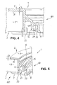
- the outer rib 11 has several introduced at its periphery 19, approximately U-shaped interruptions 16, which divides the rib into elastically deformable expansion elements 17.
- annular support flange 20 can be seen, which has a support collar 7 and two upwardly projecting ribs 21, 22 which are dimensioned so that they are in the assembled state in the aforementioned spaces 23, 24 (see. FIGS. 4 and 5 ) intervene.
- FIGS. 4 and 5 show a composed of the ring body 10 and the support flange 20, placed in the drain opening 5 receiving element 100.
- the ring body 10 is supported with its support collar 4 on the flat recess 31, with the flat side 2 of the shower bottom plate 9 preferably in flight, from and is there glued to the raw foam body 30.
- the top of the support collar 4 is arranged offset to the flat side 2 of the shower base plate 9, so that there is a height offset between the flat side 2 and the top of the support collar.
- the thickness of the support collar 4 is less than the depth T of the flat recess 31.
- the depth T may be designed so that it has a free space for a slight adhesive gap 15, which is for example 0.5 mm in size.
- a hot melt adhesive is used as an alternative to a hot melt, other adhesives come into consideration.
- the segmented rib 11 yields slightly as a result of the pressure force exerted by the upwardly directed rib 21 and presses against the inner surface 14 of the discharge opening 5 (cf. Fig. 5 ).
- the rib 22 of the support flange 20 comes with the downwardly facing inner wall 8 of the ring body 10 in surface contact or presses against them.
- the lower support collar 7 on the bottom (flat side 3) of the shower base plate 9 is tight. An aligned arrangement of the lower support collar 7 and the flat side 3 is also possible.
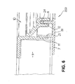
- a similar receiving element (reference numeral 200) is in Fig. 6 shown. Like reference numerals designate the same parts.
- the difference between the receiving elements 100 and 200 is that the space 24 between the inner wall. 8 and the rib 12 of the ring body 10 is narrower so that it can be filled with a liquid adhesive or suitable sealing material.
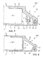
- FIG. 7 running, receiving element 300 is characterized by another rib arrangement. Instead of two, three downwardly pointing ribs 11, 12, 26 are arranged on the ring body 10, the outer rib 11 lying far away from the inner surface 14 (in the mounted state) of the drainage opening.
- the rib 21 of the support flange 20 engages between the downwardly directed ribs 11, 12 and is clamped there by frictional force.
- the second rib (reference numeral 22) of the support flange 20 engages in a filled with a liquid adhesive or suitable sealing material space 27, which is bounded by the inner wall 8 and the rib 26.
- a donut roller 13 laid in an annular manner can also be placed.
- the annular body 10 has two downwardly directed ribs 11 and 12, while the support flange 20 has three ribs 21, 22 and 28.
- the ribs 22 and 28 of the support flange 20 are filled with a liquid adhesive or suitable sealing material into which the rib 12 of the ring body 10 engages in the assembled state, so that there is a corresponding connection.
- the outer ribs 11 and 21 are directed towards each other and rest on the inner surface 14 of the drain opening 5.
- the two outer ribs 11 and 21 can be segmented.
- the shower bottom plate 9 forms together with the inserted receiving element 100; 200, 300; 400 a shower floor panel module 1.
- LIST OF REFERENCE NUMBERS 1.
- Shower floor panels module 2 3 flat side 4th Support collar (v. 10) 5th drain hole 6th inclined wall (v. 10) 7th Support collar (v. 20) 8th.
Landscapes
- Health & Medical Sciences (AREA)
- Public Health (AREA)
- Epidemiology (AREA)
- General Health & Medical Sciences (AREA)
- Life Sciences & Earth Sciences (AREA)
- Engineering & Computer Science (AREA)
- Hydrology & Water Resources (AREA)
- Water Supply & Treatment (AREA)
- Sink And Installation For Waste Water (AREA)
- Bathtubs, Showers, And Their Attachments (AREA)
- Residential Or Office Buildings (AREA)
Abstract
Die Erfindung betrifft ein Aufnahrneelement (100, 200, 300, 400) für ein Brausetassen-Scttraubventil, zum Einsetzen in eine durchgehende Ablauföffnung einer Duschbodenplatte (9), welche eine erste, ebene oder konkave Flachseite (2; 3) und eine zweite, der ersten abgewandte Flachseite (3; 2) aufweist, umfassend: - einen Ringkorpus (10), welcher von der ersten Flachseite (2; 3) in die Ablauföffnung der Duschbodenplatte (9) einlegbar ist und welcher sich mit seinem Auflagekragen (4) an der ersten Flachseite (2; 3) der Duschbodenplatte (9) abstützt, wobei der Auflagekragen (4) in eine geneigte profilierte Wand (6) des Ringkorpusses (10) übergeht und in eine zylindrische Innenwand (8) ausläuft, - und einen Stützflansch (20), welcher von der zweiten Flachseite (3; 2) der Duschbodenplatte (9) in derer Ablauföffnung einlegbar ist und welcher mit seinem Auflagekragen (7) an der zweiten Flachseite (3; 2) der Duschbodenplatte (9) aufliegt. Gemäß Erfindung weist die Wand (6) des Ringkorpusses (10) wenigstens eine umlaufende Rippe (11, 12, 26) auf, welche senkrecht oder geringfügig geneigt zum Auflagekragen (4) des Ringkorpusses (10) angeordnet ist. Der Stützflansch (20) weist ebenso wenigstens eine umlaufende Rippe (21, 22, 28) auf, welche im Wesentlichen senkrecht zum Auflagekragen (7) des Stützflansches (20) gerichtet ist, wobei die Rippen (11, 12, 26) des Ringkorpusses (10) und die Rippen (21, 22, 28) des Stützflansches (20) im zusammengefügten Zustand aufeinander gerichtet sind, und wobei wenigstens eine der Rippen (11, 12) des Ringkorpusses (10) sich mit wenigstens einer Rippe (21, 22) des Stützflansches (20) - im zusammengefügten Zustand - wenigstens teilweise miteinander verzahnen.The invention relates to a Aufnahrneelement (100, 200, 300, 400) for a shower cup Scttraubventil, for insertion into a continuous drain opening of a shower base plate (9), which a first, flat or concave flat side (2, 3) and a second, the first remote flat side (3, 2), comprising: - An annular body (10) which of the first flat side (2, 3) in the drain opening of the shower base plate (9) can be inserted and which with its support collar (4) on the first flat side (2, 3) of the shower bottom plate (9) supported, wherein the support collar (4) merges into an inclined profiled wall (6) of the ring body (10) and terminates in a cylindrical inner wall (8), - and a support flange (20) which of the second flat side (3; 2) of the shower bottom plate (9) in whose drain opening is inserted and which with its support collar (7) on the second flat side (3; 2) of the shower bottom plate (9) rests. According to the invention, the wall (6) of the ring body (10) has at least one peripheral rib (11, 12, 26) which is arranged perpendicular or slightly inclined to the support collar (4) of the ring body (10). The support flange (20) also has at least one circumferential rib (21, 22, 28), which is directed substantially perpendicular to the support collar (7) of the support flange (20), wherein the ribs (11, 12, 26) of the ring body ( 10) and the ribs (21, 22, 28) of the support flange (20) are directed towards each other in the assembled state, and wherein at least one of the ribs (11, 12) of the ring body (10) with at least one rib (21, 22) of the support flange (20) - in the assembled state - at least partially interlock.
Description
Die Erfindung betrifft ein Aufnahmeelement für ein Brausetassen-Schraubventil, zum Einsetzen in eine durchgehende Ablauföffnung einer Duschbodenplatte, welche eine erste, ebene oder konkave Flachseite und eine zweite, der ersten abgewandte Flachseite aufweist, umfassend:
- einen Ringkorpus, welcher von der ersten Flachseite in die Ablauföffnung der Duschbodenplatte einlegbar ist und welcher sich mit seinem Auflagekragen an der ersten Flachseite der Duschbodenplatte abstützt, wobei der Auflagekragen in eine geneigte profilierte Wand des Ringkorpusses übergeht und wobei die geneigte Wand in eine zylindrische Innenwand ausläuft,
- und einen Stützflansch, welcher von der zweiten Flachseite der Duschbodenplatte in derer Ablauföffnung einlegbar ist und welcher mit seinem Auflagekragen an der zweiten Flachseite der Duschbodenplatte aufliegt.
- a ring body, which is inserted from the first flat side into the drain opening of the shower base plate and which is supported with its support collar on the first flat side of the shower base plate, wherein the support collar merges into an inclined profiled wall of the Ringkorpusses and wherein the inclined wall terminates in a cylindrical inner wall .
- and a support flange which can be inserted from the second flat side of the shower base plate in whose drain opening and which rests with its support collar on the second flat side of the shower base plate.
Ferner betrifft die Erfindung einen Duschbodenplatten-Modul, bestehend aus der Duschbodenplatte und dort eingebautem Aufnahmeelement.Furthermore, the invention relates to a shower floor panel module, consisting of the shower base plate and there built-receiving element.
Ein zweiteiliges Aufnahmeelement der eingangs genannten Art sowie ein Duschbodenplatten-Modul sind von der Anmelderin unter der Produktbezeichnung "wedi Fundo Ablauf senkrecht" (zweiteiliges Aufnahmeelement) und "wedi Fundo" (Duschbodenplatten-Modul) im Markt erhältlich. Die genannten Produkte haben sich auf dem deutschen und auf den ausländischen Märkten sehr gut bewährt, jedoch besteht Bedarf an deren Weiterentwicklung zwecks Verbesserung der Konstruktion und Bereicherung des Firmenangebotes.A two-part receiving element of the type mentioned and a shower floor panel module are available from the applicant under the product name "wedi Fundo drain vertical" (two-piece receiving element) and "wedi Fundo" (shower floor panel module) in the market. The mentioned products have proved very successful in the German and foreign markets, but there is a need for their further development in order to improve the construction and enrichment of the company's offer.
Diese Aufgabe ist durch ein zweiteiliges Aufnahmeelement gemäß Oberbegriff dadurch gelöst, dass
- die Wand des Ringkorpusses wenigstens eine umlaufende Rippe aufweist, welche senkrecht oder geringfügig geneigt zum Auflagekragen des Ringkorpusses angeordnet ist,
- der Stützflansch ebenso wenigstens eine umlaufende Rippe aufweist, welche im Wesentlichen senkrecht zum Auflagekragen des Stützflansches gerichtet ist,
- the wall of the ring body has at least one circumferential rib which is arranged perpendicularly or slightly inclined to the support collar of the ring body,
- the support flange also has at least one circumferential rib, which is directed substantially perpendicular to the support collar of the support flange,
Bei der Verzahnung handelt es sich um eine gegenseitige Anordnung der umlaufenden Rippen, die miteinander wenigstens teilweise verklemmt sind oder miteinander kontaktieren. Die Rippe des Ringkorpusses kann auch kontaktfrei zwischen zwei Rippen des Stützflansches, oder umgekehrt, die Rippe des Stützflansches kann zwischen den Rippen des Ringkorpusses angeordnet sein.When the toothing is a mutual arrangement of the circumferential ribs, which are at least partially clamped together or contact each other. The rib of the ring body may also be non-contact between two ribs of the support flange, or vice versa, the rib of the support flange may be disposed between the ribs of the Ringkorpusses.
Auf diese Weise können die Rippen des Ringkorpusses und die Rippen des Stützflansches im zusammengefügten Zustand miteinander kraft-, form- und/oder stoffschlüssig verbunden sein, falls wenigstens eine Rippe elastisch verformbar ist und/oder ein Klebstoff zum Einsatz kommt. Dabei kann die zylindrische Innenwand des Ringkorpusses ebenso zu einer Rippe fungieren.In this way, the ribs of the annular body and the ribs of the support flange in the assembled state can be positively, positively and / or materially connected, if at least one rib is elastically deformable and / or an adhesive is used. In this case, the cylindrical inner wall of the ring body also act as a rib.
Das zweiteilige Aufnahmeelement kann über eine kombinierte Verbindung, beispielsweise über eine Klemm- und Klebeverbindung in der Öffnung der Duschbodenplatte festgelegt sein.The two-part receiving element can be fixed via a combined connection, for example via a clamping and adhesive connection in the opening of the shower base plate.
Es kann auch eine stoffflüssige Verbindung des Ringkorpusses und/oder des Stützflansches mit der Duschbodenplatte, beispielsweise mittels einer Klebeschicht, vorgesehen sein. Die Klebeverbindung gewährleistet eine gleichmäßige Spannungsverteilung und Kraftübertragung über die gesamte Klebfläche und kann größeren statischen und dynamischen Belastungen standhalten. Überdies kann die Klebeverbindung eine bei den Duschbodenplatten-Modulen gewünschte, dichtende Funktion übernehmen.It can also be a substance-liquid connection of the ring body and / or the support flange with the shower floor plate, for example by means of an adhesive layer may be provided. The adhesive bond ensures a uniform distribution of stress and force transmission over the entire adhesive surface and can withstand greater static and dynamic loads. Moreover, the adhesive bond can assume a sealing function desired with the shower tray panel modules.
Wenigstens eine der Rippen des Ringkorpusses und/oder des Stützflansches kann segmentiert sein. Segmentierung bedeutet, dass die Rippe an ihrem Umfang wenigstens zwei in gleichen oder ungleichen Abständen voneinander liegende Unterbrechungen aufweist, welche die Rippe in zwei oder mehrere Spreizelemente teilt. Hierdurch lässt sich der Kraftangriff bei der Montage gleichmäßig verteilen und die Rippe reagiert nachgiebiger auf elastische Verformung.At least one of the ribs of the ring body and / or the support flange may be segmented. Segmentation means that the rib has at its perimeter at least two equidistant or unequal spaced interruptions which divides the rib into two or more spreading elements. As a result, the force application during installation can be evenly distributed and the rib reacts compliant to elastic deformation.
Die beschriebene Rippenanordnung ermöglicht ein manuelles, maschinelles bzw. roboterunterstütztes Zusammenfügen der beiden Teile, d. h. des Ringkorpusses und des Stützflansches zu einer in die vorgefertigte Duschbodenplatte eingebauten Einheit.The described rib arrangement enables a manual, machine or robot-assisted assembly of the two parts, d. H. of the ring body and the support flange to a built-in prefabricated shower base plate unit.
Dementsprechend beansprucht die vorliegende Erfindung auch einen Duschbodenplatten-Modul, welcher sich aus der vorgefertigten Duschbodenplatte und dem in die Duschbodenplatte eingebauten zweiteiligen Aufnahmeelement zusammensetzt. Der Duschbodenplatten-Modul kann in dieser Form konfektioniert und angeboten werden.Accordingly, the present invention also claims a shower floor panel module composed of the prefabricated shower floor panel and the two-piece receptacle installed in the shower floor panel. The shower floor panel module can be assembled and offered in this form.
Die Duschbodenplatte kann aus Vollkunststoff, faserverstärktem Kunststoff, wie Kunstharz, oder aus einem beidseitig mit Verstärkungsschicht belegten Rohschaumkörper bestehen.The shower floor panel can be made of solid plastic, fiber-reinforced plastic, such as synthetic resin, or from a raw foam body coated with reinforcing layer on both sides.
Die Duschbodenplatte kann - in Draufsicht auf ihre Flachseite - polygonal, insbesondere rechteckig oder rund, beispielsweise kreisrund, oval, kreissegment-, nieren- oder schneckenförmig sein.The shower bottom plate can - in plan view of its flat side - be polygonal, in particular rectangular or round, for example, circular, oval, circular segment, kidney or helical.
Als Material zur Herstellung des Ringkorpusses und des Stützflansches können Thermoplaste, wie PE-HD oder Polycarbonat, Duroplaste oder Metalle vorgesehen sein.As material for the production of the Ringkorpusses and the support flange thermoplastics, such as PE-HD or polycarbonate, thermosets or metals may be provided.
Weitere Merkmale und Vorteile der Erfindung sind in mehreren Ausführungsbeispielen anhand der Zeichnung erläutert. Die Figuren zeigen:
- Fig. 1
- eine Duschbodenplatte vor dem Einmontieren des Aufnahmeelementes, in einem vereinfachten, schematischen Schnitt;
- Fig. 2
- einen Ringkorpus in einer perspektivischen Ansicht,
- Fig. 3
- einen Stützflansch in einer perspektivischen Ansicht,
- Fig. 4
- einen Duschbodenplatten-Modul, bestehend aus der Duschbodenplatte gemäß
Fig. 1 und eingebautem Aufnahmeelement, in einem Schnitt; - Fig. 5
- eine perspektivische Ansicht des Duschbodenplatten-Moduls gemäß
Fig. 4 ; - Fig. 6
- den Duschbodenplatten-Modul gemäß
Fig. 4 , mit angedeuteter Klebefüllung, in einem Schnitt und Figuren 7 und 8- andere Ausführungsbeispiele des Duschplatten-Moduls, jeweils in einem Schnitt.
- Fig. 1
- a shower floor plate before Einmontieren the receiving element, in a simplified, schematic section;
- Fig. 2
- a ring body in a perspective view,
- Fig. 3
- a support flange in a perspective view,
- Fig. 4
- a shower floor panel module, consisting of the shower floor panel according to
Fig. 1 and built-in receiving element, in a section; - Fig. 5
- a perspective view of the shower floor panel module according to
Fig. 4 ; - Fig. 6
- the shower floor panel module according to
Fig. 4 , with indicated Klebefüllung, in a cut and - FIGS. 7 and 8
- Other embodiments of the shower module, each in a section.
Die
Die Begriffe: "obere", "untere", "oben", "unten", "oberhalb" etc. beziehen sich auf die übliche Anordnung der Bodenplatte in einer Duschzelle, wie es beispielsweise den
Ein in
In einer vorteilhaften Ausführung weist die äußere Rippe 11 mehrere an ihrem Umfang 19 eingebrachte, etwa U-förmige Unterbrechungen 16 auf, welche die Rippe in elastisch verformbare Spreizelemente 17 teilt.In an advantageous embodiment, the
Der
Die
Beim Zusammenpressen der beiden Teile des Aufnahmeelementes 100 gibt die segmentierte Rippe 11 infolge der von der nach oben gerichteten Rippe 21 ausgeübten Druckkraft etwas nach und drückt gegen die Innenfläche 14 der Ablauföffnung 5 (vgl.
Ein ähnliches Aufnahmeelement (Bezugszahl 200) ist in
Ein anderes, gemäß
In
Die Duschbodenplatte 9 bildet zusammen mit dem eingesetzten Aufnahmeelement 100; 200, 300; 400 einen Duschbodenplatten-Modul 1.
Claims (9)
dadurch gekennzeichnet, dass
wobei die Rippen (11, 12, 26) des Ringkorpusses (10) und die Rippen (21, 22, 28) des Stützflansches (20) im zusammengefügten Zustand aufeinander gerichtet sind, und wobei wenigstens eine der Rippen (11, 12, 26) des Ringkorpusses (10) mit wenigstens einer Rippe (21, 22, 28) des Stützflansches (20) im zusammengefügten Zustand sich wenigstens teilweise miteinander verzahnen.
characterized in that
the ribs (11, 12, 26) of the annular body (10) and the ribs (21, 22, 28) of the supporting flange (20) facing each other in the assembled state, and at least one of the ribs (11, 12, 26) of the ring body (10) with at least one rib (21, 22, 28) of the support flange (20) in the assembled state at least partially interlock with each other.
Priority Applications (1)
| Application Number | Priority Date | Filing Date | Title |
|---|---|---|---|
| PL15002602T PL2995232T3 (en) | 2014-09-11 | 2015-09-04 | Holder element for insertion into an outlet opening of a shower tray panel and shower tray panel module |
Applications Claiming Priority (1)
| Application Number | Priority Date | Filing Date | Title |
|---|---|---|---|
| DE102014113096.0A DE102014113096A1 (en) | 2014-09-11 | 2014-09-11 | Receiving element for insertion into a drain opening of a shower base plate and shower module |
Publications (2)
| Publication Number | Publication Date |
|---|---|
| EP2995232A1 true EP2995232A1 (en) | 2016-03-16 |
| EP2995232B1 EP2995232B1 (en) | 2017-11-08 |
Family
ID=54065643
Family Applications (1)
| Application Number | Title | Priority Date | Filing Date |
|---|---|---|---|
| EP15002602.9A Not-in-force EP2995232B1 (en) | 2014-09-11 | 2015-09-04 | Holder element for insertion into an outlet opening of a shower tray panel and shower tray panel module |
Country Status (9)
| Country | Link |
|---|---|
| US (1) | US9795254B2 (en) |
| EP (1) | EP2995232B1 (en) |
| CA (1) | CA2904231A1 (en) |
| DE (1) | DE102014113096A1 (en) |
| DK (1) | DK2995232T3 (en) |
| ES (1) | ES2657343T3 (en) |
| NO (1) | NO3051027T3 (en) |
| PL (1) | PL2995232T3 (en) |
| PT (1) | PT2995232T (en) |
Citations (2)
| Publication number | Priority date | Publication date | Assignee | Title |
|---|---|---|---|---|
| DE102004036652A1 (en) * | 2003-07-28 | 2005-02-24 | Illbruck Building Systems Gmbh | A shower base element in hard foam material, especially EPP or EPS, with a preferably central drain, telescopic inner and outer parts and a mounting recess generally useful for domestic and other shower installations |
| WO2008009874A1 (en) * | 2006-07-15 | 2008-01-24 | Dlp Limited | Height-adjustable shower waste |
-
2014
- 2014-09-11 DE DE102014113096.0A patent/DE102014113096A1/en not_active Withdrawn
-
2015
- 2015-09-03 US US14/844,782 patent/US9795254B2/en not_active Expired - Fee Related
- 2015-09-04 EP EP15002602.9A patent/EP2995232B1/en not_active Not-in-force
- 2015-09-04 DK DK15002602.9T patent/DK2995232T3/en active
- 2015-09-04 PL PL15002602T patent/PL2995232T3/en unknown
- 2015-09-04 ES ES15002602.9T patent/ES2657343T3/en active Active
- 2015-09-04 PT PT150026029T patent/PT2995232T/en unknown
- 2015-09-11 CA CA2904231A patent/CA2904231A1/en not_active Abandoned
-
2016
- 2016-01-26 NO NO16152736A patent/NO3051027T3/no unknown
Patent Citations (2)
| Publication number | Priority date | Publication date | Assignee | Title |
|---|---|---|---|---|
| DE102004036652A1 (en) * | 2003-07-28 | 2005-02-24 | Illbruck Building Systems Gmbh | A shower base element in hard foam material, especially EPP or EPS, with a preferably central drain, telescopic inner and outer parts and a mounting recess generally useful for domestic and other shower installations |
| WO2008009874A1 (en) * | 2006-07-15 | 2008-01-24 | Dlp Limited | Height-adjustable shower waste |
Also Published As
| Publication number | Publication date |
|---|---|
| PL2995232T3 (en) | 2018-05-30 |
| PT2995232T (en) | 2018-01-09 |
| ES2657343T3 (en) | 2018-03-02 |
| US20160073832A1 (en) | 2016-03-17 |
| US9795254B2 (en) | 2017-10-24 |
| CA2904231A1 (en) | 2016-03-11 |
| EP2995232B1 (en) | 2017-11-08 |
| NO3051027T3 (en) | 2018-04-28 |
| DK2995232T3 (en) | 2018-01-22 |
| DE102014113096A1 (en) | 2016-03-17 |
Similar Documents
| Publication | Publication Date | Title |
|---|---|---|
| DE1750556C3 (en) | Sight glass arrangement | |
| CH649804A5 (en) | DEVICE FOR FASTENING INSULATION ON A METAL ROOF COVER. | |
| DE102013003133A1 (en) | Roof rail holder and roof rail assembly and vehicle with the roof rail assembly | |
| EP1916932B1 (en) | Combination of a rigid foam support element and a plate element, particularly as part of a shower space system | |
| DE2819016C3 (en) | Device and fasteners built into a plastic-coated worktop | |
| EP3199716A1 (en) | Packing sleeve for shower systems with floor drain, sealing system for a shower floor element, set, method for producing a substructure for a wetroom | |
| EP2000681A2 (en) | Support sleeve | |
| WO2006032476A1 (en) | Roof rack system for a motor vehicle | |
| DE102015102247B4 (en) | Shower floor plate module | |
| EP2083125A2 (en) | Drain fittings, in particular for showers or bathtubs | |
| EP2995232B1 (en) | Holder element for insertion into an outlet opening of a shower tray panel and shower tray panel module | |
| EP3453296A1 (en) | Installation of a bathtub on a supporting frame and method for mounting | |
| DE3729378C2 (en) | ||
| DE2856461A1 (en) | INSTALLATION DEVICE FOR HOLDING A PANEL-SHAPED INSTALLATION ELEMENT | |
| DE202013105785U1 (en) | Shower port with integrated drain | |
| DE606503C (en) | Device for the tight sealing of the open ends of pipes laid in the ground, intended for the reception of electrical cables | |
| DE102007010597B4 (en) | Shower tray element and method of making a shower tray element | |
| DE202016000523U1 (en) | suction holding | |
| DE202006012824U1 (en) | Sanitary surface glued to a floor support | |
| DE10308576B4 (en) | Annulus sealing | |
| DE202017104667U1 (en) | Shower base element | |
| DE102010044420A1 (en) | Zentrierdichtring for a sanitary fitting, in particular a sentry fitting | |
| DE202008007983U1 (en) | Floor audit device | |
| DE10322046B4 (en) | support means | |
| EP4470433A1 (en) | Sanitary tub assembly |
Legal Events
| Date | Code | Title | Description |
|---|---|---|---|
| PUAI | Public reference made under article 153(3) epc to a published international application that has entered the european phase |
Free format text: ORIGINAL CODE: 0009012 |
|
| AK | Designated contracting states |
Kind code of ref document: A1 Designated state(s): AL AT BE BG CH CY CZ DE DK EE ES FI FR GB GR HR HU IE IS IT LI LT LU LV MC MK MT NL NO PL PT RO RS SE SI SK SM TR |
|
| AX | Request for extension of the european patent |
Extension state: BA ME |
|
| 17P | Request for examination filed |
Effective date: 20160726 |
|
| RBV | Designated contracting states (corrected) |
Designated state(s): AL AT BE BG CH CY CZ DE DK EE ES FI FR GB GR HR HU IE IS IT LI LT LU LV MC MK MT NL NO PL PT RO RS SE SI SK SM TR |
|
| GRAP | Despatch of communication of intention to grant a patent |
Free format text: ORIGINAL CODE: EPIDOSNIGR1 |
|
| INTG | Intention to grant announced |
Effective date: 20170418 |
|
| GRAS | Grant fee paid |
Free format text: ORIGINAL CODE: EPIDOSNIGR3 |
|
| GRAA | (expected) grant |
Free format text: ORIGINAL CODE: 0009210 |
|
| AK | Designated contracting states |
Kind code of ref document: B1 Designated state(s): AL AT BE BG CH CY CZ DE DK EE ES FI FR GB GR HR HU IE IS IT LI LT LU LV MC MK MT NL NO PL PT RO RS SE SI SK SM TR |
|
| REG | Reference to a national code |
Ref country code: GB Ref legal event code: FG4D Free format text: NOT ENGLISH |
|
| REG | Reference to a national code |
Ref country code: CH Ref legal event code: EP Ref country code: AT Ref legal event code: REF Ref document number: 943350 Country of ref document: AT Kind code of ref document: T Effective date: 20171115 |
|
| REG | Reference to a national code |
Ref country code: IE Ref legal event code: FG4D Free format text: LANGUAGE OF EP DOCUMENT: GERMAN |
|
| REG | Reference to a national code |
Ref country code: DE Ref legal event code: R096 Ref document number: 502015002269 Country of ref document: DE |
|
| REG | Reference to a national code |
Ref country code: PT Ref legal event code: SC4A Ref document number: 2995232 Country of ref document: PT Date of ref document: 20180109 Kind code of ref document: T Free format text: AVAILABILITY OF NATIONAL TRANSLATION Effective date: 20180103 |
|
| REG | Reference to a national code |
Ref country code: CH Ref legal event code: NV Representative=s name: R.A. EGLI AND CO, PATENTANWAELTE, CH |
|
| REG | Reference to a national code |
Ref country code: DK Ref legal event code: T3 Effective date: 20180115 |
|
| REG | Reference to a national code |
Ref country code: SE Ref legal event code: TRGR |
|
| REG | Reference to a national code |
Ref country code: NL Ref legal event code: FP |
|
| REG | Reference to a national code |
Ref country code: ES Ref legal event code: FG2A Ref document number: 2657343 Country of ref document: ES Kind code of ref document: T3 Effective date: 20180302 |
|
| REG | Reference to a national code |
Ref country code: EE Ref legal event code: FG4A Ref document number: E014823 Country of ref document: EE Effective date: 20180131 |
|
| REG | Reference to a national code |
Ref country code: LT Ref legal event code: MG4D |
|
| REG | Reference to a national code |
Ref country code: NO Ref legal event code: T2 Effective date: 20171108 |
|
| PG25 | Lapsed in a contracting state [announced via postgrant information from national office to epo] |
Ref country code: LT Free format text: LAPSE BECAUSE OF FAILURE TO SUBMIT A TRANSLATION OF THE DESCRIPTION OR TO PAY THE FEE WITHIN THE PRESCRIBED TIME-LIMIT Effective date: 20171108 |
|
| PG25 | Lapsed in a contracting state [announced via postgrant information from national office to epo] |
Ref country code: IS Free format text: LAPSE BECAUSE OF FAILURE TO SUBMIT A TRANSLATION OF THE DESCRIPTION OR TO PAY THE FEE WITHIN THE PRESCRIBED TIME-LIMIT Effective date: 20180308 Ref country code: HR Free format text: LAPSE BECAUSE OF FAILURE TO SUBMIT A TRANSLATION OF THE DESCRIPTION OR TO PAY THE FEE WITHIN THE PRESCRIBED TIME-LIMIT Effective date: 20171108 Ref country code: GR Free format text: LAPSE BECAUSE OF FAILURE TO SUBMIT A TRANSLATION OF THE DESCRIPTION OR TO PAY THE FEE WITHIN THE PRESCRIBED TIME-LIMIT Effective date: 20180209 Ref country code: RS Free format text: LAPSE BECAUSE OF FAILURE TO SUBMIT A TRANSLATION OF THE DESCRIPTION OR TO PAY THE FEE WITHIN THE PRESCRIBED TIME-LIMIT Effective date: 20171108 Ref country code: BG Free format text: LAPSE BECAUSE OF FAILURE TO SUBMIT A TRANSLATION OF THE DESCRIPTION OR TO PAY THE FEE WITHIN THE PRESCRIBED TIME-LIMIT Effective date: 20180208 |
|
| PG25 | Lapsed in a contracting state [announced via postgrant information from national office to epo] |
Ref country code: CY Free format text: LAPSE BECAUSE OF FAILURE TO SUBMIT A TRANSLATION OF THE DESCRIPTION OR TO PAY THE FEE WITHIN THE PRESCRIBED TIME-LIMIT Effective date: 20171108 Ref country code: CZ Free format text: LAPSE BECAUSE OF FAILURE TO SUBMIT A TRANSLATION OF THE DESCRIPTION OR TO PAY THE FEE WITHIN THE PRESCRIBED TIME-LIMIT Effective date: 20171108 Ref country code: SK Free format text: LAPSE BECAUSE OF FAILURE TO SUBMIT A TRANSLATION OF THE DESCRIPTION OR TO PAY THE FEE WITHIN THE PRESCRIBED TIME-LIMIT Effective date: 20171108 |
|
| REG | Reference to a national code |
Ref country code: DE Ref legal event code: R097 Ref document number: 502015002269 Country of ref document: DE |
|
| PG25 | Lapsed in a contracting state [announced via postgrant information from national office to epo] |
Ref country code: RO Free format text: LAPSE BECAUSE OF FAILURE TO SUBMIT A TRANSLATION OF THE DESCRIPTION OR TO PAY THE FEE WITHIN THE PRESCRIBED TIME-LIMIT Effective date: 20171108 Ref country code: SM Free format text: LAPSE BECAUSE OF FAILURE TO SUBMIT A TRANSLATION OF THE DESCRIPTION OR TO PAY THE FEE WITHIN THE PRESCRIBED TIME-LIMIT Effective date: 20171108 |
|
| PLBE | No opposition filed within time limit |
Free format text: ORIGINAL CODE: 0009261 |
|
| STAA | Information on the status of an ep patent application or granted ep patent |
Free format text: STATUS: NO OPPOSITION FILED WITHIN TIME LIMIT |
|
| PG25 | Lapsed in a contracting state [announced via postgrant information from national office to epo] |
Ref country code: MT Free format text: LAPSE BECAUSE OF FAILURE TO SUBMIT A TRANSLATION OF THE DESCRIPTION OR TO PAY THE FEE WITHIN THE PRESCRIBED TIME-LIMIT Effective date: 20171108 |
|
| 26N | No opposition filed |
Effective date: 20180809 |
|
| PGFP | Annual fee paid to national office [announced via postgrant information from national office to epo] |
Ref country code: IT Payment date: 20180930 Year of fee payment: 4 |
|
| PG25 | Lapsed in a contracting state [announced via postgrant information from national office to epo] |
Ref country code: SI Free format text: LAPSE BECAUSE OF FAILURE TO SUBMIT A TRANSLATION OF THE DESCRIPTION OR TO PAY THE FEE WITHIN THE PRESCRIBED TIME-LIMIT Effective date: 20171108 |
|
| REG | Reference to a national code |
Ref country code: EE Ref legal event code: MM4A Ref document number: E014823 Country of ref document: EE Effective date: 20180930 |
|
| REG | Reference to a national code |
Ref country code: NO Ref legal event code: MMEP |
|
| PG25 | Lapsed in a contracting state [announced via postgrant information from national office to epo] |
Ref country code: LV Free format text: LAPSE BECAUSE OF NON-PAYMENT OF DUE FEES Effective date: 20180904 Ref country code: MC Free format text: LAPSE BECAUSE OF FAILURE TO SUBMIT A TRANSLATION OF THE DESCRIPTION OR TO PAY THE FEE WITHIN THE PRESCRIBED TIME-LIMIT Effective date: 20171108 Ref country code: FI Free format text: LAPSE BECAUSE OF NON-PAYMENT OF DUE FEES Effective date: 20180904 |
|
| REG | Reference to a national code |
Ref country code: SE Ref legal event code: EUG Ref country code: CH Ref legal event code: PL |
|
| REG | Reference to a national code |
Ref country code: DK Ref legal event code: EBP Effective date: 20180930 |
|
| REG | Reference to a national code |
Ref country code: NL Ref legal event code: MM Effective date: 20181001 |
|
| PG25 | Lapsed in a contracting state [announced via postgrant information from national office to epo] |
Ref country code: SE Free format text: LAPSE BECAUSE OF NON-PAYMENT OF DUE FEES Effective date: 20180905 |
|
| REG | Reference to a national code |
Ref country code: BE Ref legal event code: MM Effective date: 20180930 |
|
| REG | Reference to a national code |
Ref country code: IE Ref legal event code: MM4A |
|
| PG25 | Lapsed in a contracting state [announced via postgrant information from national office to epo] |
Ref country code: NL Free format text: LAPSE BECAUSE OF NON-PAYMENT OF DUE FEES Effective date: 20181001 Ref country code: LU Free format text: LAPSE BECAUSE OF NON-PAYMENT OF DUE FEES Effective date: 20180904 |
|
| PG25 | Lapsed in a contracting state [announced via postgrant information from national office to epo] |
Ref country code: NO Free format text: LAPSE BECAUSE OF NON-PAYMENT OF DUE FEES Effective date: 20180930 Ref country code: PT Free format text: LAPSE BECAUSE OF NON-PAYMENT OF DUE FEES Effective date: 20190604 Ref country code: IE Free format text: LAPSE BECAUSE OF NON-PAYMENT OF DUE FEES Effective date: 20180904 |
|
| PG25 | Lapsed in a contracting state [announced via postgrant information from national office to epo] |
Ref country code: BE Free format text: LAPSE BECAUSE OF NON-PAYMENT OF DUE FEES Effective date: 20180930 Ref country code: EE Free format text: LAPSE BECAUSE OF NON-PAYMENT OF DUE FEES Effective date: 20180930 Ref country code: CH Free format text: LAPSE BECAUSE OF NON-PAYMENT OF DUE FEES Effective date: 20180930 Ref country code: FR Free format text: LAPSE BECAUSE OF NON-PAYMENT OF DUE FEES Effective date: 20180930 Ref country code: LI Free format text: LAPSE BECAUSE OF NON-PAYMENT OF DUE FEES Effective date: 20180930 |
|
| REG | Reference to a national code |
Ref country code: ES Ref legal event code: FD2A Effective date: 20191030 |
|
| PG25 | Lapsed in a contracting state [announced via postgrant information from national office to epo] |
Ref country code: DK Free format text: LAPSE BECAUSE OF NON-PAYMENT OF DUE FEES Effective date: 20180930 |
|
| PG25 | Lapsed in a contracting state [announced via postgrant information from national office to epo] |
Ref country code: PL Free format text: LAPSE BECAUSE OF NON-PAYMENT OF DUE FEES Effective date: 20180904 Ref country code: ES Free format text: LAPSE BECAUSE OF NON-PAYMENT OF DUE FEES Effective date: 20180905 |
|
| PG25 | Lapsed in a contracting state [announced via postgrant information from national office to epo] |
Ref country code: TR Free format text: LAPSE BECAUSE OF FAILURE TO SUBMIT A TRANSLATION OF THE DESCRIPTION OR TO PAY THE FEE WITHIN THE PRESCRIBED TIME-LIMIT Effective date: 20171108 |
|
| PG25 | Lapsed in a contracting state [announced via postgrant information from national office to epo] |
Ref country code: HU Free format text: LAPSE BECAUSE OF FAILURE TO SUBMIT A TRANSLATION OF THE DESCRIPTION OR TO PAY THE FEE WITHIN THE PRESCRIBED TIME-LIMIT; INVALID AB INITIO Effective date: 20150904 Ref country code: MK Free format text: LAPSE BECAUSE OF NON-PAYMENT OF DUE FEES Effective date: 20171108 |
|
| REG | Reference to a national code |
Ref country code: DE Ref legal event code: R082 Ref document number: 502015002269 Country of ref document: DE Representative=s name: DR. TRAEGER & STRAUTMANN PATENTANWAELTE PARTNE, DE |
|
| PG25 | Lapsed in a contracting state [announced via postgrant information from national office to epo] |
Ref country code: AL Free format text: LAPSE BECAUSE OF FAILURE TO SUBMIT A TRANSLATION OF THE DESCRIPTION OR TO PAY THE FEE WITHIN THE PRESCRIBED TIME-LIMIT Effective date: 20171108 |
|
| PG25 | Lapsed in a contracting state [announced via postgrant information from national office to epo] |
Ref country code: IT Free format text: LAPSE BECAUSE OF NON-PAYMENT OF DUE FEES Effective date: 20190904 |
|
| GBPC | Gb: european patent ceased through non-payment of renewal fee |
Effective date: 20190904 |
|
| PG25 | Lapsed in a contracting state [announced via postgrant information from national office to epo] |
Ref country code: GB Free format text: LAPSE BECAUSE OF NON-PAYMENT OF DUE FEES Effective date: 20190904 |
|
| PGFP | Annual fee paid to national office [announced via postgrant information from national office to epo] |
Ref country code: DE Payment date: 20200916 Year of fee payment: 6 |
|
| REG | Reference to a national code |
Ref country code: AT Ref legal event code: MM01 Ref document number: 943350 Country of ref document: AT Kind code of ref document: T Effective date: 20200904 |
|
| PG25 | Lapsed in a contracting state [announced via postgrant information from national office to epo] |
Ref country code: AT Free format text: LAPSE BECAUSE OF NON-PAYMENT OF DUE FEES Effective date: 20200904 |
|
| REG | Reference to a national code |
Ref country code: DE Ref legal event code: R119 Ref document number: 502015002269 Country of ref document: DE |
|
| PG25 | Lapsed in a contracting state [announced via postgrant information from national office to epo] |
Ref country code: DE Free format text: LAPSE BECAUSE OF NON-PAYMENT OF DUE FEES Effective date: 20220401 |