EP2995189B1 - Combined cam and reel arm - Google Patents
Combined cam and reel arm Download PDFInfo
- Publication number
- EP2995189B1 EP2995189B1 EP15183792.9A EP15183792A EP2995189B1 EP 2995189 B1 EP2995189 B1 EP 2995189B1 EP 15183792 A EP15183792 A EP 15183792A EP 2995189 B1 EP2995189 B1 EP 2995189B1
- Authority
- EP
- European Patent Office
- Prior art keywords
- cam
- reel
- header
- tine
- support
- Prior art date
- Legal status (The legal status is an assumption and is not a legal conclusion. Google has not performed a legal analysis and makes no representation as to the accuracy of the status listed.)
- Active
Links
- 230000002093 peripheral effect Effects 0.000 claims description 5
- 238000003306 harvesting Methods 0.000 description 15
- 230000008901 benefit Effects 0.000 description 8
- 230000007246 mechanism Effects 0.000 description 8
- 241000239290 Araneae Species 0.000 description 5
- 239000000463 material Substances 0.000 description 5
- 238000004519 manufacturing process Methods 0.000 description 2
- 230000002411 adverse Effects 0.000 description 1
- 230000003466 anti-cipated effect Effects 0.000 description 1
- 238000010276 construction Methods 0.000 description 1
- 230000001419 dependent effect Effects 0.000 description 1
- 238000006073 displacement reaction Methods 0.000 description 1
- 238000003197 gene knockdown Methods 0.000 description 1
- 230000003993 interaction Effects 0.000 description 1
- 238000012423 maintenance Methods 0.000 description 1
- 238000000034 method Methods 0.000 description 1
- 239000002699 waste material Substances 0.000 description 1
Images


Classifications
-
- A—HUMAN NECESSITIES
- A01—AGRICULTURE; FORESTRY; ANIMAL HUSBANDRY; HUNTING; TRAPPING; FISHING
- A01D—HARVESTING; MOWING
- A01D57/00—Delivering mechanisms for harvesters or mowers
- A01D57/01—Devices for leading crops to the mowing apparatus
- A01D57/02—Devices for leading crops to the mowing apparatus using reels
- A01D57/04—Arrangements for changing the position of the reels
Definitions
- the present invention relates generally to agricultural harvesting machines having crop harvesting headers, such as combines, and, more particularly to harvesting machines having a reel positioned above a cutting mechanism for assisting in feeding of crop material through the harvesting header.
- the reel including a plurality of tine bars having axially spaced tines therealong, guides the crop material to be harvested towards a cutter bar extending between header sidewalls, and the cut crop is transported on a draper or auger transport arrangement into the harvester for further processing.
- the tine bars are mounted for pivotal movement about a respective tine bar axis generally parallel to a reel rotational axis.
- a cam typically mounted between the sidewall and an end of the rotary reel, in cooperation with linkages to each tine bar, controls the pivotal movement of the tine bars and thus the angular orientation of the tines thereon.
- the tines on each tine bar follow a predetermined path defined by the cam for lifting, separating, and guiding crop material towards the cutter bar and beyond.
- the reel may also be supported by a plurality of reel arms which enable adjustment of the position of the reel in relation to the cutterbar.
- the reel positon may be adjusted vertically and/or in a fore-aft direction to provide optimal movement of the crop material.
- One solution to the problem is to shift the lateral position of the reel arm to a position outboard of the header sidewall so that the reel end and cam may be positioned as close as possible to the sidewall.
- This design generally increases the lateral width of the sidewall increases crop knock down (waste) as the sidewall width increases.
- An alternative design splits the reel into two or more portions and relocates the cams and a supporting reel arm to an inboard position between adjacent reel portions.
- Such a design requires two cams (one for each reel portion) and supporting structure needed to connect the cams to a reel arm.
- the resulting structure creates a dead zone in the reel width (gap between adjacent reel portions) of approximately 0,20 m (8 inches) and effectively relocates the crop flow problems from the outboard ends of the reel to the center cam location.
- European patent EP 1297735 discloses an exemplary crop harvesting header using a cam system for controlling the movement trajectory of the reel fingers.
- the present invention in any of the embodiments described herein, may provide one or more of the following advantages: It is an object of the present invention to provide an integrated reel arm and reel cam for use in an agricultural harvesting header that positions both within the same lateral space in order to reduce the width of the integrated assembly.
- the reduced width reel arm and cam may be positioned at an intermediate position long the reel width or it may be positioned at one or both outboard ends where the reduced width enables the non-cutting width of the header to be reduced.
- a reel arm is connected to a reel cam in a manner minimizing the width of the integral assembly.
- An end of the reel arm distal to the reel cam is configured to attach to a reel arm position adjusting mechanism on the header thereby enabling the narrow profile reel cam to be position adjusted as is possible on Applicant's current production headers.
- connection between the reel arm and the reel cam may include a bolted connection with slotted holes on the arm or the cam to allow limited movement of one relative to the other so that the cam may be rotated slightly about the reel axis thereby enabling adjustment of cam timing.
- an integrated reel arm and reel cam for use in an agricultural harvesting header that positions both within the same lateral space in order to reduce the width of the integrated assembly.
- the reel arm connects directly to a rearwardly facing structure on the reel cam and may include adjustment means for varying cam timing.
- the lateral width of the reel arm and connection is configured to be no greater than the lateral width of the reel cam thereby enabling positioning of a reel cam between adjacent reels in little more than the lateral width of the cam itself.
- the integrated reel arm and reel cam may also benefit conventional outboard reel cam configurations by reducing the lateral space requirements at the ends of a header reel.
- any reference herein to the terms “left” or “right” are used as a matter of mere convenience, and are determined by standing at the rear of the machine facing in its normal direction of travel. Likewise, “forward” and “rearward” are determined by the normal direction of travel. “Upward” and “downward” orientations are relative to the ground or operating surface as are any references to “horizontal” or “vertical” planes.
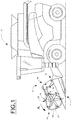
- FIG. 1 illustrates a conventional agricultural harvester, a combine 10 in this instance, having a forwardly mounted header 15 for processing a standing crop as the harvester moves across a field.
- the header 15 is transversely arranged on the harvester and includes a laterally extending cutterbar 17 for severing the standing crop from the ground.
- a transversely arranged tine reel 20 is also provided and positioned generally parallel to and above the cutterbar to guide the standing crop into the header and toward the cutterbar.
- the header 15 is vertically moveable in relation to the harvester so that the header may float over irregularities in the ground and maintain the cutterbar 17 in a desired proximity to the ground. Systems controlling header float are well known in the art and are not discussed further herein.
- Mechanisms capable of repositioning the tine reel 20 vertically as well as in a fore-aft direction may be provided.
- Such mechanisms typically include moveable arms positioned at each end of the tine reel with a bearing disposed on each arm rotatably supporting an axle 52 on which the tine reel rotates.
- the tine reel 20 comprises at least a pair of spaced apart reel spiders 21 engaged on the axle being supported at each end by outboard supports 50 for rotation about a reel axis 101.
- the spiders 21 in turn support a plurality of pivotally moveable tine bars 22 which orbital about reel axis 101 as the spiders 21 rotate about the reel axis. Additional spiders may be intermediately positioned between the outboard spiders for additional tine bar support in wider reels.
- each tine bar 22 To each tine bar 22 is connected a plurality of tines 24, the angle of the tines being varied by pivotal movement of the tine bars 22 to angularly orient the connected tines 24 for most effective crop movement as the reel 20 rotates.
- Pivotal position of the tine bars 22 is managed by one or more cams 28 disposed on a cam support structure 26.
- Each tine bar includes a follower 29 interacting with one of the cams 28 and connected by a linkage 27 to the tine bar 22.
- the followers 29 travel along cam 28 and vary the pivotal position of each tine bar 22, dependent upon the orbital position of the tine bar.
- the cam 28 is fixed in relation to the reel rotational axis 101 by the cam support structure 26 while the followers 29 orbit with the reel and follow the cam contours.
- the cam structure 26 is conventionally connected to the reel support 50 in a manner positioning the cam support laterally adjacent to the reel support arm. Using such a configuration in a center-mounted cam and reel support location requires approximately 8 inches of lateral space. This unfortunately creates an 8 inch wide gap in the tine reel leaving in the incoming standing crop unguided as it enters the header. See FIG. 4 .
- the cam support 26 includes a support bearing for the reel axle generally centrally positioned and a connection for a modified reel support 30 generally positioned at the periphery of the cam.
- the reel support arm for connection to the cam structure and moving the tine reel support bearing from the support arm to the cam support
- the reel support 30 and the cam/cam support structure may be configured to fit within the same lateral space rather than in a laterally adjacent arrangement. This configuration when used in a center-mounted cam and reel support reduces the space required (tine reel dead space) from approximately 0,20 m (8 inches) to approximately 0,05 m (2 inches).
- the reel 20 and cam structure 26 are connected to the header structure 19 by a reel support 30.
- the reel support 30 includes a first member 31 pivotally connected to the header structure at pivot 312 and configured to allow generally vertical positioning of the reel 20 by means of lift actuator 32.
- Pivot 312 is arranged generally parallel to the reel axis 101. While pivoting movement provides a small amount of fore-aft movement of the reel axis 101, the position of the pivot 312 generally behind and beneath the reel axis results in predominately vertical movement of the reel axis as the first member 31 is pivoted.
- a second member 34 interacting with the first member 31 through a sliding interface 342 is connected at one end to the cam structure 26.
- the end opposite of the cam structure connection 37 of the second member 34 engages the sliding interface 342 which allows the second member to be positioned along a sliding axis 103 by reach actuator 36.
- the orientation of the sliding axis 103 is orthogonal to the reel axis and may vary from horizontal depending on the pivoting positon of the first member 31. As a result, a small amount of vertical displacement may accompany the fore-aft movement by sliding the second member; however, fore and aft movement is the predominate movement afforded by the sliding interface 342. Movement of the second member 34 allows the fore-aft position of the tine reel 20 in relation to the cutterbar to be adjusted for optimal performance.
- the present reel support 30 invention is shown disposed in an intermediate position on a header.
- the tine reel 20 comprises two portions, right 20R and left 20L, respectively.
- the present invention minimizes the lateral space "W" necessary for the reel support arm 30 and cams 28R, 28L. Headers having a single tine reel may also benefit as the space requirements for a reel support arm and cam disposed at one end of the reel are similarly reduced thereby allowing the width of the non-crop processing portion of the header ends to be reduced accordingly.
- the cam support 26 is intermediately positioned in a split tine reel, the shared cam support 26 including two cams 28L, 28R, two followers 29R, 29L, and two linkages 27R, 27L, one mechanism for each tine reel portion 20L, 20R.
- This configuration provides the maximum benefit of the present invention as the lateral width necessary to locate the tine bar cam and linkage is minimized and the outboard supports 50 can be configured for minimal lateral width resulting in the minimum dead space across the entirety of the header width.
- the shared cam support 26 reduces the weight of the cam assembly compared to two complete cam and cam support structures without reducing structural capability.
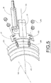
- the cam structure connection 37 of present invention includes a plurality of slotted openings 372 that engage bolts 265 on the peripheral surface 261 of the cam structure 26.
- the slotted openings 372 are oriented to allow finite movement of the cam structure 26 about the tine reel axis 101 thereby enabling cam time adjustment.
Landscapes
- Life Sciences & Earth Sciences (AREA)
- Environmental Sciences (AREA)
- Outside Dividers And Delivering Mechanisms For Harvesters (AREA)
- Harvesting Machines For Root Crops (AREA)
Applications Claiming Priority (1)
| Application Number | Priority Date | Filing Date | Title |
|---|---|---|---|
| US14/479,195 US10201125B2 (en) | 2014-09-05 | 2014-09-05 | Combined center cam and reel arm |
Publications (2)
| Publication Number | Publication Date |
|---|---|
| EP2995189A1 EP2995189A1 (en) | 2016-03-16 |
| EP2995189B1 true EP2995189B1 (en) | 2018-11-14 |
Family
ID=54064198
Family Applications (1)
| Application Number | Title | Priority Date | Filing Date |
|---|---|---|---|
| EP15183792.9A Active EP2995189B1 (en) | 2014-09-05 | 2015-09-04 | Combined cam and reel arm |
Country Status (3)
| Country | Link |
|---|---|
| US (1) | US10201125B2 (pt) |
| EP (1) | EP2995189B1 (pt) |
| BR (1) | BR102015021487B1 (pt) |
Cited By (1)
| Publication number | Priority date | Publication date | Assignee | Title |
|---|---|---|---|---|
| WO2022226246A1 (en) * | 2021-04-21 | 2022-10-27 | Cnh Industrial America Llc | Harvester reel having self-adjusting tine bars |
Families Citing this family (7)
| Publication number | Priority date | Publication date | Assignee | Title |
|---|---|---|---|---|
| LT3307054T (lt) * | 2015-06-11 | 2019-12-10 | Stw S R L | Patobulinta teleskopinė ritė |
| US10238033B2 (en) * | 2017-02-27 | 2019-03-26 | Cnh Industrial America Llc | Reel finger assembly for a harvesting reel |
| US10368490B2 (en) * | 2017-07-28 | 2019-08-06 | Cnh Industrial America Llc | Crop divider for an agricultural harvester header having multiple harvesting reels |
| WO2019055743A1 (en) | 2017-09-15 | 2019-03-21 | Cnh Industrial America Llc | CAM TRACK ADJUSTMENT ASSEMBLY FOR A HARVEST RESTORER |
| CN108738664B (zh) * | 2018-05-02 | 2020-12-18 | 华中农业大学 | 一种梳割式向日葵收割方法及割台 |
| EP3669636B1 (en) * | 2018-12-20 | 2022-08-10 | CNH Industrial Belgium NV | A split reel combine header |
| US11395457B2 (en) * | 2020-02-20 | 2022-07-26 | Cnh Industrial America Llc | Combine headers with fold up cutterbars |
Family Cites Families (15)
| Publication number | Priority date | Publication date | Assignee | Title |
|---|---|---|---|---|
| US4297833A (en) * | 1979-10-11 | 1981-11-03 | Hesston Corporation | Crop pickup with outboard cam control |
| US6442918B1 (en) | 2000-09-27 | 2002-09-03 | Macdon Industries Ltd. | Adjustment of a pickup reel of a crop harvesting header |
| US6868659B2 (en) * | 2001-01-26 | 2005-03-22 | Arbuckle Ranch, Inc. | Native seed harvester with cam design |
| US20020148210A1 (en) | 2001-04-12 | 2002-10-17 | Hcc, Inc. | Harvester pickup reel |
| CA2387898C (en) | 2001-06-18 | 2005-01-11 | Macdon Industries Ltd. | Multi-section header with flexible crop cutting knife |
| US6591598B2 (en) | 2001-10-01 | 2003-07-15 | Macdon Industries Ltd. | Crop harvesting header with cam controlled movement of the reel fingers |
| US6651411B1 (en) * | 2002-08-09 | 2003-11-25 | Deere & Company | Fore/aft position sensor for a harvesting reel |
| DE102004024234A1 (de) | 2004-05-15 | 2005-12-15 | Deere & Company, Moline | Haspelzusammenbau |
| US7426817B2 (en) * | 2006-03-02 | 2008-09-23 | Deere & Company | Independent center reel position adjustment for an agricultural harvesting machine |
| US7805921B2 (en) * | 2006-06-14 | 2010-10-05 | Deere & Company | Reel height control for flexible cutting platform in an agricultural harvesting machine |
| US7866132B2 (en) * | 2009-05-20 | 2011-01-11 | Deere & Company | Harvesting head reel support arrangement including hydraulic cylinders and control circuitry |
| US8176716B2 (en) * | 2010-08-31 | 2012-05-15 | Deere & Company | Flexible reel for an agricultural harvesting head |
| US8863489B2 (en) * | 2011-03-30 | 2014-10-21 | H & S Manufacturing Co., Inc. | Tine drive cam for windrow merger |
| US8590284B2 (en) * | 2011-05-31 | 2013-11-26 | Cnh America Llc | Cam shield for a rotary reel |
| US20130160418A1 (en) * | 2011-12-23 | 2013-06-27 | Agco Corporation | Support for Reel or Auger with Single Piece Tube |
-
2014
- 2014-09-05 US US14/479,195 patent/US10201125B2/en active Active
-
2015
- 2015-09-03 BR BR102015021487-1A patent/BR102015021487B1/pt active IP Right Grant
- 2015-09-04 EP EP15183792.9A patent/EP2995189B1/en active Active
Non-Patent Citations (1)
| Title |
|---|
| None * |
Cited By (1)
| Publication number | Priority date | Publication date | Assignee | Title |
|---|---|---|---|---|
| WO2022226246A1 (en) * | 2021-04-21 | 2022-10-27 | Cnh Industrial America Llc | Harvester reel having self-adjusting tine bars |
Also Published As
| Publication number | Publication date |
|---|---|
| US10201125B2 (en) | 2019-02-12 |
| EP2995189A1 (en) | 2016-03-16 |
| US20160066510A1 (en) | 2016-03-10 |
| BR102015021487A2 (pt) | 2018-05-02 |
| BR102015021487B1 (pt) | 2020-09-29 |
Similar Documents
| Publication | Publication Date | Title |
|---|---|---|
| EP2995189B1 (en) | Combined cam and reel arm | |
| EP3469878B1 (en) | Roll center for harvester attachment frame control arms | |
| EP2529613B1 (en) | Cam shield for a rotary reel | |
| EP2420128B1 (en) | Flexible draper belt drive for an agricultural harvesting machine | |
| EP3258771B1 (en) | Hood divider adjustment apparatus for an agricultural harvester | |
| US9788486B2 (en) | Grain header with swathing and chopping capability | |
| EP3585146B1 (en) | Reel finger assembly for a harvesting reel | |
| EP2420127B1 (en) | Spring assisted translating draper belt drive rollers for an agricultural harvesting machine | |
| JP2011200188A (ja) | コンバイン | |
| EP3469880B1 (en) | Reel header with a rotatable coupler for a reel arm | |
| EP3434097B1 (en) | Crop divider for an agricultural harvester header having multiple harvesting reels | |
| JP2011177075A (ja) | コンバイン | |
| US10537063B2 (en) | Folding agricultural head | |
| JP2011188747A (ja) | コンバイン | |
| CN205336893U (zh) | 联合收割机的拨禾轮的前后移动控制装置 | |
| EP3669636B1 (en) | A split reel combine header | |
| US20220124981A1 (en) | Reel assembly of an agricultural header | |
| KR102352998B1 (ko) | 콤바인 | |
| JP2003000033A (ja) | コンバインの株元移送装置 | |
| JP2878225B2 (ja) | コンバインの刈取前処理装置 | |
| JPH0710204B2 (ja) | 全稈投入型コンバインの刈取ロ−リング装置 | |
| JPH0439287B2 (pt) | ||
| JP2003259716A (ja) | コンバイン | |
| JPH10215642A (ja) | コンバインの刈取部支持構造 | |
| JP2013223444A (ja) | コンバイン |
Legal Events
| Date | Code | Title | Description |
|---|---|---|---|
| PUAI | Public reference made under article 153(3) epc to a published international application that has entered the european phase |
Free format text: ORIGINAL CODE: 0009012 |
|
| AK | Designated contracting states |
Kind code of ref document: A1 Designated state(s): AL AT BE BG CH CY CZ DE DK EE ES FI FR GB GR HR HU IE IS IT LI LT LU LV MC MK MT NL NO PL PT RO RS SE SI SK SM TR |
|
| AX | Request for extension of the european patent |
Extension state: BA ME |
|
| 17P | Request for examination filed |
Effective date: 20160916 |
|
| RBV | Designated contracting states (corrected) |
Designated state(s): AL AT BE BG CH CY CZ DE DK EE ES FI FR GB GR HR HU IE IS IT LI LT LU LV MC MK MT NL NO PL PT RO RS SE SI SK SM TR |
|
| GRAP | Despatch of communication of intention to grant a patent |
Free format text: ORIGINAL CODE: EPIDOSNIGR1 |
|
| STAA | Information on the status of an ep patent application or granted ep patent |
Free format text: STATUS: GRANT OF PATENT IS INTENDED |
|
| INTG | Intention to grant announced |
Effective date: 20180405 |
|
| GRAS | Grant fee paid |
Free format text: ORIGINAL CODE: EPIDOSNIGR3 |
|
| GRAA | (expected) grant |
Free format text: ORIGINAL CODE: 0009210 |
|
| STAA | Information on the status of an ep patent application or granted ep patent |
Free format text: STATUS: THE PATENT HAS BEEN GRANTED |
|
| AK | Designated contracting states |
Kind code of ref document: B1 Designated state(s): AL AT BE BG CH CY CZ DE DK EE ES FI FR GB GR HR HU IE IS IT LI LT LU LV MC MK MT NL NO PL PT RO RS SE SI SK SM TR |
|
| REG | Reference to a national code |
Ref country code: CH Ref legal event code: EP Ref country code: AT Ref legal event code: REF Ref document number: 1063697 Country of ref document: AT Kind code of ref document: T Effective date: 20181115 |
|
| REG | Reference to a national code |
Ref country code: IE Ref legal event code: FG4D |
|
| REG | Reference to a national code |
Ref country code: DE Ref legal event code: R096 Ref document number: 602015019743 Country of ref document: DE |
|
| REG | Reference to a national code |
Ref country code: NL Ref legal event code: MP Effective date: 20181114 |
|
| REG | Reference to a national code |
Ref country code: LT Ref legal event code: MG4D |
|
| REG | Reference to a national code |
Ref country code: AT Ref legal event code: MK05 Ref document number: 1063697 Country of ref document: AT Kind code of ref document: T Effective date: 20181114 |
|
| PG25 | Lapsed in a contracting state [announced via postgrant information from national office to epo] |
Ref country code: LV Free format text: LAPSE BECAUSE OF FAILURE TO SUBMIT A TRANSLATION OF THE DESCRIPTION OR TO PAY THE FEE WITHIN THE PRESCRIBED TIME-LIMIT Effective date: 20181114 Ref country code: FI Free format text: LAPSE BECAUSE OF FAILURE TO SUBMIT A TRANSLATION OF THE DESCRIPTION OR TO PAY THE FEE WITHIN THE PRESCRIBED TIME-LIMIT Effective date: 20181114 Ref country code: NO Free format text: LAPSE BECAUSE OF FAILURE TO SUBMIT A TRANSLATION OF THE DESCRIPTION OR TO PAY THE FEE WITHIN THE PRESCRIBED TIME-LIMIT Effective date: 20190214 Ref country code: LT Free format text: LAPSE BECAUSE OF FAILURE TO SUBMIT A TRANSLATION OF THE DESCRIPTION OR TO PAY THE FEE WITHIN THE PRESCRIBED TIME-LIMIT Effective date: 20181114 Ref country code: BG Free format text: LAPSE BECAUSE OF FAILURE TO SUBMIT A TRANSLATION OF THE DESCRIPTION OR TO PAY THE FEE WITHIN THE PRESCRIBED TIME-LIMIT Effective date: 20190214 Ref country code: AT Free format text: LAPSE BECAUSE OF FAILURE TO SUBMIT A TRANSLATION OF THE DESCRIPTION OR TO PAY THE FEE WITHIN THE PRESCRIBED TIME-LIMIT Effective date: 20181114 Ref country code: HR Free format text: LAPSE BECAUSE OF FAILURE TO SUBMIT A TRANSLATION OF THE DESCRIPTION OR TO PAY THE FEE WITHIN THE PRESCRIBED TIME-LIMIT Effective date: 20181114 Ref country code: IS Free format text: LAPSE BECAUSE OF FAILURE TO SUBMIT A TRANSLATION OF THE DESCRIPTION OR TO PAY THE FEE WITHIN THE PRESCRIBED TIME-LIMIT Effective date: 20190314 Ref country code: ES Free format text: LAPSE BECAUSE OF FAILURE TO SUBMIT A TRANSLATION OF THE DESCRIPTION OR TO PAY THE FEE WITHIN THE PRESCRIBED TIME-LIMIT Effective date: 20181114 |
|
| PG25 | Lapsed in a contracting state [announced via postgrant information from national office to epo] |
Ref country code: GR Free format text: LAPSE BECAUSE OF FAILURE TO SUBMIT A TRANSLATION OF THE DESCRIPTION OR TO PAY THE FEE WITHIN THE PRESCRIBED TIME-LIMIT Effective date: 20190215 Ref country code: PT Free format text: LAPSE BECAUSE OF FAILURE TO SUBMIT A TRANSLATION OF THE DESCRIPTION OR TO PAY THE FEE WITHIN THE PRESCRIBED TIME-LIMIT Effective date: 20190314 Ref country code: NL Free format text: LAPSE BECAUSE OF FAILURE TO SUBMIT A TRANSLATION OF THE DESCRIPTION OR TO PAY THE FEE WITHIN THE PRESCRIBED TIME-LIMIT Effective date: 20181114 Ref country code: RS Free format text: LAPSE BECAUSE OF FAILURE TO SUBMIT A TRANSLATION OF THE DESCRIPTION OR TO PAY THE FEE WITHIN THE PRESCRIBED TIME-LIMIT Effective date: 20181114 Ref country code: AL Free format text: LAPSE BECAUSE OF FAILURE TO SUBMIT A TRANSLATION OF THE DESCRIPTION OR TO PAY THE FEE WITHIN THE PRESCRIBED TIME-LIMIT Effective date: 20181114 Ref country code: SE Free format text: LAPSE BECAUSE OF FAILURE TO SUBMIT A TRANSLATION OF THE DESCRIPTION OR TO PAY THE FEE WITHIN THE PRESCRIBED TIME-LIMIT Effective date: 20181114 |
|
| PG25 | Lapsed in a contracting state [announced via postgrant information from national office to epo] |
Ref country code: CZ Free format text: LAPSE BECAUSE OF FAILURE TO SUBMIT A TRANSLATION OF THE DESCRIPTION OR TO PAY THE FEE WITHIN THE PRESCRIBED TIME-LIMIT Effective date: 20181114 Ref country code: PL Free format text: LAPSE BECAUSE OF FAILURE TO SUBMIT A TRANSLATION OF THE DESCRIPTION OR TO PAY THE FEE WITHIN THE PRESCRIBED TIME-LIMIT Effective date: 20181114 Ref country code: DK Free format text: LAPSE BECAUSE OF FAILURE TO SUBMIT A TRANSLATION OF THE DESCRIPTION OR TO PAY THE FEE WITHIN THE PRESCRIBED TIME-LIMIT Effective date: 20181114 |
|
| REG | Reference to a national code |
Ref country code: DE Ref legal event code: R097 Ref document number: 602015019743 Country of ref document: DE |
|
| PG25 | Lapsed in a contracting state [announced via postgrant information from national office to epo] |
Ref country code: SM Free format text: LAPSE BECAUSE OF FAILURE TO SUBMIT A TRANSLATION OF THE DESCRIPTION OR TO PAY THE FEE WITHIN THE PRESCRIBED TIME-LIMIT Effective date: 20181114 Ref country code: SK Free format text: LAPSE BECAUSE OF FAILURE TO SUBMIT A TRANSLATION OF THE DESCRIPTION OR TO PAY THE FEE WITHIN THE PRESCRIBED TIME-LIMIT Effective date: 20181114 Ref country code: EE Free format text: LAPSE BECAUSE OF FAILURE TO SUBMIT A TRANSLATION OF THE DESCRIPTION OR TO PAY THE FEE WITHIN THE PRESCRIBED TIME-LIMIT Effective date: 20181114 Ref country code: RO Free format text: LAPSE BECAUSE OF FAILURE TO SUBMIT A TRANSLATION OF THE DESCRIPTION OR TO PAY THE FEE WITHIN THE PRESCRIBED TIME-LIMIT Effective date: 20181114 |
|
| PLBE | No opposition filed within time limit |
Free format text: ORIGINAL CODE: 0009261 |
|
| STAA | Information on the status of an ep patent application or granted ep patent |
Free format text: STATUS: NO OPPOSITION FILED WITHIN TIME LIMIT |
|
| 26N | No opposition filed |
Effective date: 20190815 |
|
| PG25 | Lapsed in a contracting state [announced via postgrant information from national office to epo] |
Ref country code: SI Free format text: LAPSE BECAUSE OF FAILURE TO SUBMIT A TRANSLATION OF THE DESCRIPTION OR TO PAY THE FEE WITHIN THE PRESCRIBED TIME-LIMIT Effective date: 20181114 |
|
| PG25 | Lapsed in a contracting state [announced via postgrant information from national office to epo] |
Ref country code: TR Free format text: LAPSE BECAUSE OF FAILURE TO SUBMIT A TRANSLATION OF THE DESCRIPTION OR TO PAY THE FEE WITHIN THE PRESCRIBED TIME-LIMIT Effective date: 20181114 |
|
| PG25 | Lapsed in a contracting state [announced via postgrant information from national office to epo] |
Ref country code: MC Free format text: LAPSE BECAUSE OF FAILURE TO SUBMIT A TRANSLATION OF THE DESCRIPTION OR TO PAY THE FEE WITHIN THE PRESCRIBED TIME-LIMIT Effective date: 20181114 |
|
| REG | Reference to a national code |
Ref country code: CH Ref legal event code: PL |
|
| PG25 | Lapsed in a contracting state [announced via postgrant information from national office to epo] |
Ref country code: LI Free format text: LAPSE BECAUSE OF NON-PAYMENT OF DUE FEES Effective date: 20190930 Ref country code: IE Free format text: LAPSE BECAUSE OF NON-PAYMENT OF DUE FEES Effective date: 20190904 Ref country code: LU Free format text: LAPSE BECAUSE OF NON-PAYMENT OF DUE FEES Effective date: 20190904 Ref country code: CH Free format text: LAPSE BECAUSE OF NON-PAYMENT OF DUE FEES Effective date: 20190930 |
|
| PG25 | Lapsed in a contracting state [announced via postgrant information from national office to epo] |
Ref country code: CY Free format text: LAPSE BECAUSE OF FAILURE TO SUBMIT A TRANSLATION OF THE DESCRIPTION OR TO PAY THE FEE WITHIN THE PRESCRIBED TIME-LIMIT Effective date: 20181114 |
|
| PG25 | Lapsed in a contracting state [announced via postgrant information from national office to epo] |
Ref country code: HU Free format text: LAPSE BECAUSE OF FAILURE TO SUBMIT A TRANSLATION OF THE DESCRIPTION OR TO PAY THE FEE WITHIN THE PRESCRIBED TIME-LIMIT; INVALID AB INITIO Effective date: 20150904 Ref country code: MT Free format text: LAPSE BECAUSE OF FAILURE TO SUBMIT A TRANSLATION OF THE DESCRIPTION OR TO PAY THE FEE WITHIN THE PRESCRIBED TIME-LIMIT Effective date: 20181114 |
|
| PG25 | Lapsed in a contracting state [announced via postgrant information from national office to epo] |
Ref country code: MK Free format text: LAPSE BECAUSE OF FAILURE TO SUBMIT A TRANSLATION OF THE DESCRIPTION OR TO PAY THE FEE WITHIN THE PRESCRIBED TIME-LIMIT Effective date: 20181114 |
|
| PGFP | Annual fee paid to national office [announced via postgrant information from national office to epo] |
Ref country code: IT Payment date: 20230912 Year of fee payment: 9 Ref country code: GB Payment date: 20230920 Year of fee payment: 9 |
|
| PGFP | Annual fee paid to national office [announced via postgrant information from national office to epo] |
Ref country code: FR Payment date: 20230922 Year of fee payment: 9 Ref country code: DE Payment date: 20230928 Year of fee payment: 9 Ref country code: BE Payment date: 20230920 Year of fee payment: 9 |