EP2994765B1 - Erkennung von erdfehlern in energieversorgungsnetzen mit kompensiertem sternpunkt - Google Patents
Erkennung von erdfehlern in energieversorgungsnetzen mit kompensiertem sternpunkt Download PDFInfo
- Publication number
- EP2994765B1 EP2994765B1 EP13729633.1A EP13729633A EP2994765B1 EP 2994765 B1 EP2994765 B1 EP 2994765B1 EP 13729633 A EP13729633 A EP 13729633A EP 2994765 B1 EP2994765 B1 EP 2994765B1
- Authority
- EP
- European Patent Office
- Prior art keywords
- admittance
- energy supply
- system voltage
- supply network
- zero phase
- Prior art date
- Legal status (The legal status is an assumption and is not a legal conclusion. Google has not performed a legal analysis and makes no representation as to the accuracy of the status listed.)
- Active
Links
Images



Classifications
-
- H—ELECTRICITY
- H02—GENERATION; CONVERSION OR DISTRIBUTION OF ELECTRIC POWER
- H02H—EMERGENCY PROTECTIVE CIRCUIT ARRANGEMENTS
- H02H3/00—Emergency protective circuit arrangements for automatic disconnection directly responsive to an undesired change from normal electric working condition with or without subsequent reconnection ; integrated protection
- H02H3/16—Emergency protective circuit arrangements for automatic disconnection directly responsive to an undesired change from normal electric working condition with or without subsequent reconnection ; integrated protection responsive to fault current to earth, frame or mass
- H02H3/162—Emergency protective circuit arrangements for automatic disconnection directly responsive to an undesired change from normal electric working condition with or without subsequent reconnection ; integrated protection responsive to fault current to earth, frame or mass for AC systems
-
- G—PHYSICS
- G01—MEASURING; TESTING
- G01R—MEASURING ELECTRIC VARIABLES; MEASURING MAGNETIC VARIABLES
- G01R31/00—Arrangements for testing electric properties; Arrangements for locating electric faults; Arrangements for electrical testing characterised by what is being tested not provided for elsewhere
- G01R31/50—Testing of electric apparatus, lines, cables or components for short-circuits, continuity, leakage current or incorrect line connections
- G01R31/52—Testing for short-circuits, leakage current or ground faults
-
- H—ELECTRICITY
- H02—GENERATION; CONVERSION OR DISTRIBUTION OF ELECTRIC POWER
- H02H—EMERGENCY PROTECTIVE CIRCUIT ARRANGEMENTS
- H02H7/00—Emergency protective circuit arrangements specially adapted for specific types of electric machines or apparatus or for sectionalised protection of cable or line systems, and effecting automatic switching in the event of an undesired change from normal working conditions
- H02H7/26—Sectionalised protection of cable or line systems, e.g. for disconnecting a section on which a short-circuit, earth fault, or arc discharge has occured
- H02H7/261—Sectionalised protection of cable or line systems, e.g. for disconnecting a section on which a short-circuit, earth fault, or arc discharge has occured involving signal transmission between at least two stations
-
- G—PHYSICS
- G01—MEASURING; TESTING
- G01R—MEASURING ELECTRIC VARIABLES; MEASURING MAGNETIC VARIABLES
- G01R31/00—Arrangements for testing electric properties; Arrangements for locating electric faults; Arrangements for electrical testing characterised by what is being tested not provided for elsewhere
- G01R31/08—Locating faults in cables, transmission lines, or networks
- G01R31/081—Locating faults in cables, transmission lines, or networks according to type of conductors
- G01R31/086—Locating faults in cables, transmission lines, or networks according to type of conductors in power transmission or distribution networks, i.e. with interconnected conductors
Definitions
- the invention relates to a method for detecting a ground fault in an electrical power supply network with compensated neutral point, in which measured values are recorded at at least one measuring point of the power supply network, which characterize a state of the power supply network, from the measured values a zero system voltage and an admittance are determined and the zero system voltage and the Admittanzsupplementary be used to detect the earth fault in the power grid.
- the invention also relates to a corresponding electrical protection device and a protection system.
- Ground faults ie faulty low-resistance electrical connections of a phase conductor to earth, form the majority of the faults in three-phase electrical energy supply networks. They are caused, for example, by contact with trees grown on the line or by lightning or are based on a destruction of the line with subsequent earth contact. In some cases, these are permanent ground faults, sometimes also short-term faults, so-called "ground fault wipers".
- Electric power grids can be operated with different grounding variants with respect to their neutral point.
- Grounded neutral power grids that have an effective electrical connection between their star point and ground ensure high symmetry between the individual phase currents and voltages, but in this variant, high fault currents flow in the event of a single earth fault due to the electrically closed phase-earth loop , which must immediately lead to a shutdown of the faulty line. Therefore, be Power supply networks in certain voltage levels (eg in the range of the medium voltage between 6kV and 110kV) often operated with isolated or compensated ("cleared") star point.
- a method of the type mentioned is, for example, from the international patent application WO 01/22104 A1 known.
- the detection of a ground fault is carried out on the basis of a zero system voltage and an admittance quantity in the form of a phase-earth admittance and a symmetry parameter indicating a degree of asymmetry.
- a grounding device for example a so-called “BUD” circuit
- KNOSPE short low-impedance star point grounding
- ANCF method Active Neutral Current Forcing
- the invention is therefore based on the object of specifying a comparatively simple way of detecting a pending ground fault, with which even high-impedance earth faults are reliably detected.
- the stated object is achieved by a method of the type specified, in which, in the presence of measured values, which indicate an earth fault in the power grid, the neutral point of the power grid is temporarily connected to earth by connecting a grounding device, and a ground fault in the power grid is detected when both the zero system voltage exceeds a predetermined zero system voltage threshold and the Admittanzlik a predetermined admittance threshold during the connected grounding device, wherein the connection of the grounding device causes a reduction of the zero system voltage threshold.
- the invention is based on the finding that possible incorrect decisions in the detection of high-impedance ground fault in compensated power supply networks while using a grounding device, such as the Boss-automatic, often due to the fact that when activated grounding device, ie at the temporary grounding of the neutral point of the power grid , the zero system voltage drops significantly. With increasing fault resistance, this effect increases. Therefore, it is contemplated by the present invention to adaptively adjust the zero system voltage threshold to the status of the grounding device by lowering the zero system voltage threshold when the grounding device is activated. This can also be comparatively clear Breaking the zero system voltage is still a reliable error detection done when the admittance criterion used indicates a ground fault.
- An advantageous development of the method according to the invention provides that the reduction of the zero system voltage threshold value is withdrawn after a predetermined delay time.
- the delay time can be fixed here and e.g. correspond to an activation cycle of the grounding device, i. that period of time that the grounding device usually remains in the activated position and connects the neutral point of the power supply network with ground.
- the delay time can also be set in such a way that after the decision has been made on the existence of a ground fault, i. deciding whether or not there is a ground fault. In the latter case, the duration of the delay time can be different, since its end is triggered in each case by the decision about the ground fault.
- a combination of the two alternatives is also conceivable, for example in such a way that the delay time can be terminated by the decision about the error, however, a maximum of a predetermined period of time takes.
- the use of the above relationship allows a comparatively simple adjustment of the reduction of the zero system voltage threshold, since the operator of a device with which the method is performed, for example an electrical distance protection device, in addition to the already determined zero system voltage threshold only the reduction factor as a parameter in the device must adjust.
- Possible values of the reduction factor are, for example, between 0.5 and 1.
- admittance variable provision can also be made for the admittance variable to be a zero-system admittance or the real part of the zero-system admittance, the so-called “conductance” or “conductance”.
- admittance quantities for example combinations of admittance, conductance and / or susceptance (imaginary part of the admittance) can also be used as admittance variables used.
- the zero system voltage may be compared to the - not reduced - zero system voltage threshold to determine if the zero system voltage is significantly increased.
- the decision to activate the grounding device a separately set threshold for to use the zero system voltage.
- the activation of the grounding device can be effected either by an independent control device or by the same device, which also performs the method for earth fault detection with adaptive adaptation of the zero system voltage threshold.
- the error signal can serve as information for the operator of the power supply network on the one hand, to indicate the affected by the earth fault line.
- the line can be temporarily operated even in the presence of a ground fault due to the comparatively low fault currents until an opportunity for troubleshooting.
- the earth fault must be detected and assigned to a line.
- the error signal causes the switching off of a switching device.
- the switching device may be e.g. to act a circuit breaker, with which the line affected by the earth fault line can be separated from the rest of the power grid.
- the method is carried out for several lines in the electrical energy supply network, wherein the zero system voltage for the power supply network is determined as a whole and the admittance for each line is determined separately, and the line as from affected by the earth fault is detected for which the admittance size exceeds the predetermined admittance threshold.
- an electrical protection device for detecting earth faults in compensated neutral power supply networks with a measuring device for acquiring measured values which characterize a state of the energy supply network, and for determining a zero system voltage and an admittance variable from the measured values and with an error detection device adapted to perform earth fault detection using zero system voltage and admittance magnitude.
- the protective device is set up to cooperate with a grounding device which, in the presence of measured values which indicate an earth fault in the power supply network, connects the neutral point of the power supply network to ground, and the fault detection device is set up to detect a ground fault in the ground fault Detecting the power supply network when both the zero system voltage exceeds a predetermined zero system voltage threshold and the Admittanzlik a predetermined admittance threshold during the connected grounding device, the error detection device is also adapted to make with the connection of the grounding device, a reduction of the zero system voltage threshold.
- a protection system for detecting ground faults in compensated neutral power supply networks with a grounding device which connects the neutral point of the power supply network to earth in the presence of measured values characterizing a state of the energy supply network, which indicate an earth fault in the energy supply network. and at least one electrical protection device formed according to claim 9.
- FIG. 1 is a schematic representation of a part of an electrical energy supply network 10 is shown, which is for example a medium-voltage power supply network.
- a busbar 11 is fed by a transformer 12, the star point of the secondary side of the transformer 12 is connected via an inductance L, for example, a so-called "Petersenspule" to ground, so that the power supply network 10 is operated as a compensated network.
- an ohmic resistance R of a grounding device 13 is arranged, via which the star point of the power supply network 10 can be connected directly to ground if necessary.
- the grounding device 13 has a control device 13a which cooperates with a switching device 13b to switch the current flow through the ohmic resistor R on or off. On the exact operation of the grounding device 13 will be discussed later.
- branch lines 14a-c From the busbar 11 go from three branch lines 14a-c, for example, to in FIG. 1 can lead to electrical loads not shown.
- the branch lines 14a-c are connected to the busbar 11 via switching devices 15a-c.
- electrical protective devices 16a-c respectively arranged, which by means of a in FIG. 1 not explicitly shown measuring device on in FIG. 1 only schematically indicated current and voltage transformers capture current and voltage readings. In this case, the voltage measured values on the busbar for the energy supply network 10 are detected in total, while the current measured values for each branch line 14a-c are detected separately.
- the protection devices 16a-c are also connected to the grounding device 13 to report the state of a status contact of the grounding device 13 to the protection devices 16a-c.
- This can be like in FIG. 1 indicated, for example, via a communication bus 17, via which the state of the grounding device 13 in the form of a telegram, for example of a GOOSE (Generic Object Oriented Substation Event) telegram in accordance with the standard IEC 61850 for communication in switchgear.
- a communication bus 17 via which the state of the grounding device 13 in the form of a telegram, for example of a GOOSE (Generic Object Oriented Substation Event) telegram in accordance with the standard IEC 61850 for communication in switchgear.
- GOOSE Generic Object Oriented Substation Event
- the protective devices serve to monitor the branch lines 14a-c of the power supply network 10 for earth faults. Is exemplary in the FIG. 1 an earth fault with respect to branch line 14b at location 18 is shown.
- the protective devices 16a-c receive measured values with their measuring devices and determine therefrom a zero system voltage U 0 and an admittance variable, for example a zero system admittance Y 0 or a zero system conductance G 0 . Based on the zero system voltage U 0 and the admittance size, the protective devices 16a-c check by means of an error detection device whether there is an earth fault on their respective branch line 14a-c. The presence of a ground fault is detected if and only if both the zero system voltage and the admittance size are above respective threshold values.
- the protection devices 16a-c additionally take into account information about the current state of the grounding device 13, since when the grounding device 13 is activated, ie when the switching device 13a is closed, the zero system voltage U 0 in the power supply network 10 compares to the grounding situation the inductance L drops significantly despite the pending ground fault. In order to take this effect into account, the protective devices 16a-c temporarily lower the zero system voltage threshold U 0P used for evaluating the zero system voltage U 0 when the grounding device 13 is activated.
- U 0 P ' k R ⁇ U 0 P .
- U 0P is the normally used zero voltage threshold
- U ' 0P is the zero-span threshold after the reduction
- k R is an adjustable reduction factor.
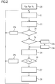
- FIG. 2 a process flow diagram with the individual carried out for Erd Beingerkennung steps.
- a first step 20 the method is initialized once, ie settings required by an operator of the protection devices are defined as parameters, including the values for the zero system voltage threshold U 0P and the admittance threshold G 0P .
- the admittance variable considered is the zero-system conductance or the zero-system conductance G 0 .
- the reduction factor k R is set in step 20, which indicates the factor by which the zero system voltage threshold is to be lowered when the grounding device 13 is activated.
- the reduction factor k R can be selected, for example, between 0.5 and 1.
- the reduced zero system voltage threshold U ' 0P is also set to the same value as the zero system voltage threshold U 0P .
- the actual monitoring phase begins with step 21.
- Measured values are thereby recorded by the protective devices 16a-c by means of integrated measuring devices, which characterize a state of the electrical power supply network.
- the measured values can be, for example, phase currents and voltages and / or zero system currents and voltages.
- the measured values can preferably be detected as so-called phasor measured values, ie pointer measured values in the complex number plane, which include information on both the amplitude and the phase angle of the measured variable under consideration.
- the formation of such phase measured values can be carried out in the respective protective device 16a-c or in an upstream measuring device, for example a so-called "phasor measurement unit" (PMU).
- PMU phase measurement unit
- the variables required for detecting a ground fault ie a zero system voltage U 0 and an admittance variable in the form of the zero-system conductance G 0, are formed from the measured values. This can be done, for example, with a digital signal processor of the respective protective device 16a-c that has been specially adapted to the processing of the measured value.
- step 23 the state of the grounding device 13 is checked below. Specifically, it is checked here whether the grounding device 13 is in an activated (switching device 13a closed) or a non-activated (switching device 13a open) state. This can be indicated for example via a status contact of the grounding device 13 and transmitted via the communication bus 17 to the protective devices 16a-c.
- the grounding device 13 is activated by the control device 13b for measured values which indicate a ground fault in the energy supply network 10. These are the control device 13b, for example, supplied to the busbar of the power grid voltage measured values and evaluated by this. In this case, the evaluation may comprise a determination of a zero system voltage U 0 , it being possible to deduce an earth fault in the energy supply network 10 given an increased zero system voltage U 0 .
- the decision on the activation of the grounding device 13 may deviate from the representation in FIG. 1 be taken by one of the protective devices 16a-c.
- the comparison value for the zero system voltage U 0 with respect to the activation of the grounding device 13 can be set, for example, to the zero system voltage threshold value U 0P , but also to another suitable value.
- the decision on the activation of the grounding device 13 is in the flowchart according to FIG. 2 not explicitly shown.
- step 23 If the test in step 23 shows that the earthing device 13 is not activated, the method restarts in step 21, because the power supply network is considered faultless in this case due to the lack of increase of the zero system voltage U 0 .
- a timer for the delay time T TD is deactivated in step 23a.
- step 24 determines whether the timer check in step 24 indicates that it is already active, ie the expiration of the delay time T TD has already been started. If the timer check in step 24 indicates that it is already active, ie the expiration of the delay time T TD has already been started, the process continues directly at step 25.
- step 25 the earth fault criteria are checked for the presence of a ground fault.
- the admittance quantity in the form of the zero-system conductance G 0 is compared with the admittance threshold value G 0P .
- the admittance threshold G 0P usually does not consist of a single value but of one or more characteristics, as exemplified in FIGS. 3A and 3B are shown. It shows FIG. 3A an admittance diagram in which the zero system conductance G 0 (the real part of the admittance) and the zero system susceptance jB 0 (the imaginary part of the admittance) are plotted in the complex number plane. In addition, characteristic curves are drawn which determine the admittance threshold value G 0 in the positive and negative directions. That puts FIG. 3A the admittance threshold for an undirected earth fault detection, ie the error is detected and displayed regardless of the error direction.
- exceeding the admittance threshold by the admittance G 0 means either exceeding the positive threshold G 0P or below the negative threshold -G 0P .
- the location of the admittance threshold for a directional earth fault detection, ie the error is detected seen only in one direction (forward direction) from the protection device.
- an excess of the admittance threshold value by the admittance G 0 is only caused by exceeding the positive threshold G 0P .
- the zero system voltage U 0 is compared with the reduced zero system voltage threshold U ' 0P . If both the admittance quantity G 0 and the zero system voltage U 0 exceed the respective threshold values, the result is the check in Step 25 generates a start signal indicating an indication of a present earth fault.
- the status of the timer of the delay time T TD is then checked in step 26.
- step 26a If the elapsed time t since the activation of the timer t is smaller than the delay time T TD , then the counter of the timer of the delay time T TD is incrementally increased in step 26a and the process is continued again at step 21.
- step 27 the last pending decision regarding the presence of a ground fault according to step 25 is implemented.
- an error signal is thus generated upon detection of the presence of a ground fault.
- This error signal is emitted by the protective device 16a-c (see FIG. 1) with respect to whose line the error has been detected. In the example off FIG. 1 Consequently, the error signal is output from the protection device 16b with respect to the earth fault on the branch line 14b.
- the error signal can either be used only as a warning to the operator of the power supply network 10, which indicates the presence of the earth fault with respect to the particular branch line, so that the error can be eliminated at the earliest opportunity.
- the error signal can also cause the generation of a switch-off signal or trip signal, which is output from the protective device 16b to the switching device 15b and causes them to open their switch contacts to separate the faulty branch line 14b from the rest of the power grid 10 and a smooth continued operation of the allow error-free part of the power supply network 10.
- step 28 the zero system voltage threshold is raised from its reduced value U ' 0P back to the original value U 0P . Thereafter, the process starts again with step 21.
- the method described above is usually carried out by a protective device by means of a measuring device and an error detection device while processing a device software.
- the steps 20-28 described in this case represent program steps of the device software.
- the individual steps can also be implemented, for example, by electronic elements of the protective device.
- FIGS. 4 and 5 Finally, in a respective diagram show the time course of Erdêtkriterien zero system voltage U 0 and admittance in the form of the zero system conductance G 0 , for example in the case of a high-impedance ground fault with a fault resistance of 5k ⁇ . It shows FIG. 4 the situation without adaptive adjustment of the zero system voltage threshold U 0P during FIG. 5 represents the situation with adaptive adaptation of the zero system voltage threshold U 0P or U ' 0P .
- the activation of the grounding device leads by the grounding of the star point on the one hand to a significant increase in the current flowing through the fault location, as shown by the significant increase of the admittance G 0 .
- the grounding of the star point causes a significant decrease in the zero system voltage U 0 .
- This effect occurs more strongly the higher the fault resistance.
Landscapes
- Engineering & Computer Science (AREA)
- Power Engineering (AREA)
- Physics & Mathematics (AREA)
- General Physics & Mathematics (AREA)
- Testing Of Short-Circuits, Discontinuities, Leakage, Or Incorrect Line Connections (AREA)
Priority Applications (1)
| Application Number | Priority Date | Filing Date | Title |
|---|---|---|---|
| PL13729633T PL2994765T3 (pl) | 2013-06-05 | 2013-06-05 | Wykrywanie usterek uziemienia w sieciach elektroenergetycznych ze skompensowanym punktem neutralnym |
Applications Claiming Priority (1)
| Application Number | Priority Date | Filing Date | Title |
|---|---|---|---|
| PCT/EP2013/061545 WO2014194941A1 (de) | 2013-06-05 | 2013-06-05 | Erkennung von erdfehlern in energieversorgungsnetzen mit kompensiertem sternpunkt |
Publications (2)
| Publication Number | Publication Date |
|---|---|
| EP2994765A1 EP2994765A1 (de) | 2016-03-16 |
| EP2994765B1 true EP2994765B1 (de) | 2018-11-28 |
Family
ID=48651998
Family Applications (1)
| Application Number | Title | Priority Date | Filing Date |
|---|---|---|---|
| EP13729633.1A Active EP2994765B1 (de) | 2013-06-05 | 2013-06-05 | Erkennung von erdfehlern in energieversorgungsnetzen mit kompensiertem sternpunkt |
Country Status (3)
| Country | Link |
|---|---|
| EP (1) | EP2994765B1 (pl) |
| PL (1) | PL2994765T3 (pl) |
| WO (1) | WO2014194941A1 (pl) |
Families Citing this family (11)
| Publication number | Priority date | Publication date | Assignee | Title |
|---|---|---|---|---|
| SE539485C2 (sv) * | 2016-05-20 | 2017-10-03 | Swedish Neutral Holding Ab | System och metod för lokalisering av jordfel i kraftnät |
| AT519450B1 (de) * | 2017-02-09 | 2018-07-15 | Sprecher Automation Gmbh | Verfahren zur Steuerung eines Distanzschutzrelais durch Erkennung von Leiter-Erde-Fehlern |
| EP3389157B1 (en) * | 2017-04-10 | 2020-01-01 | ABB Schweiz AG | Method for improvement of earth-fault protection in compensated mv networks |
| CN108445347A (zh) * | 2018-04-28 | 2018-08-24 | 广东电网有限责任公司 | 一种基于线路等效阻抗值的单相接地故障检测方法 |
| CN109541379B (zh) * | 2019-01-18 | 2020-09-01 | 云南电网有限责任公司电力科学研究院 | 可控电压源接地电流全补偿的选线方法及装置 |
| CN109541380B (zh) * | 2019-01-18 | 2020-04-24 | 云南电网有限责任公司电力科学研究院 | 一种可控电压源接地电流全补偿扰动选线方法及装置 |
| EP3713029A1 (de) * | 2019-03-18 | 2020-09-23 | Siemens Aktiengesellschaft | Orten eines erdschlusses in einem gleichstromnetz mit mehreren lastzonen |
| CN109813997B (zh) * | 2019-04-02 | 2021-02-02 | 云南电网有限责任公司电力科学研究院 | 一种可控电流源接地电流全补偿输出电流计算方法及系统 |
| DE102020002618A1 (de) | 2020-04-30 | 2021-11-04 | A. Eberle Gmbh & Co. Kg | Verfahren zur Erkennung und/oder Ortung von Erdschlüssen |
| CN112130091B (zh) * | 2020-09-24 | 2023-12-12 | 中国南方电网有限责任公司超高压输电公司梧州局 | 基于多源数据的变电站不接地系统单相接地在线监测方法 |
| CN119644046B (zh) * | 2024-12-23 | 2025-09-30 | 国网河南省电力公司郑州供电公司 | 基于零序电压周期差分能量的接地故障识别方法 |
Family Cites Families (10)
| Publication number | Priority date | Publication date | Assignee | Title |
|---|---|---|---|---|
| FI106985B (fi) * | 1999-09-23 | 2001-05-15 | Abb Substation Automation Oy | Menetelmä sähkönjakeluverkon maasulkuvian etäisyyden määrittämiseksi laskennallisesti rengaskytkennässä |
| FI112283B (fi) | 1999-09-23 | 2003-11-14 | Abb Oy | Menetelmä keskijänniteverkon suuri-impedanssisten maasulkuvikojen ilmaisemiseksi |
| AT411937B (de) * | 2000-08-11 | 2004-07-26 | Adaptive Regelsysteme Ges M B | Verfahren und vorrichtung zur erkennung und ortung von hochohmigen einpoligen erdfehlern |
| DE10302451B3 (de) * | 2003-01-22 | 2004-07-15 | Edc Gmbh | Verfahren zur Erkennung der Richtung eines Erdschlusses |
| AT413769B (de) * | 2002-06-26 | 2006-05-15 | Adaptive Regelsysteme Gmbh | Verfahren zur bestimmung eines parameters eines elektrischen netzes |
| DE10307972B4 (de) * | 2003-02-24 | 2007-02-08 | Edc Gmbh | Verfahren zur Erkennung und Ortung von niederohmigen und hochohmigen Erdschlüssen in elektrischen Versorgungsnetzen |
| DE102004008994B4 (de) * | 2004-02-20 | 2005-12-22 | Becker, Wolf, Dipl.-Ing. | Verfahren und Schaltungsanordnung zur Fehlerdiagnose in Hochspannungsnetzen |
| AT503929B1 (de) * | 2007-02-01 | 2008-02-15 | Adaptive Regelsysteme Ges M B | Vorrichtung und ein verfahren zur injektion eines hilfssignals in das nullsystem eines elektrischen verteilnetzes |
| US8462004B2 (en) * | 2008-04-03 | 2013-06-11 | Siemens Aktiengesellschaft | Method and arrangement for generating an error signal |
| EP2756571B1 (de) * | 2011-10-28 | 2016-04-06 | Siemens Aktiengesellschaft | Verfahren und schutzgerät zum erkennen eines erdfehlers in einem mehrphasigen elektrischen energieversorgungsnetz mit kompensiertem oder isoliertem sternpunkt |
-
2013
- 2013-06-05 PL PL13729633T patent/PL2994765T3/pl unknown
- 2013-06-05 WO PCT/EP2013/061545 patent/WO2014194941A1/de not_active Ceased
- 2013-06-05 EP EP13729633.1A patent/EP2994765B1/de active Active
Non-Patent Citations (1)
| Title |
|---|
| None * |
Also Published As
| Publication number | Publication date |
|---|---|
| WO2014194941A1 (de) | 2014-12-11 |
| EP2994765A1 (de) | 2016-03-16 |
| PL2994765T3 (pl) | 2019-07-31 |
Similar Documents
| Publication | Publication Date | Title |
|---|---|---|
| EP2994765B1 (de) | Erkennung von erdfehlern in energieversorgungsnetzen mit kompensiertem sternpunkt | |
| EP2476002B1 (de) | Fehlererkennung in energieversorgungsnetzen mit ungeerdetem oder gelöschtem sternpunkt | |
| DE112012001189B4 (de) | Verfahren, Systeme und Einrichtungen zum Erkennen paralleler elektrischer Fehlerlichtbögen | |
| EP2635911B1 (de) | Überwachung einer einseitig gespeisten energieversorgungsleitung auf erdkurzschlüsse | |
| EP2301128B1 (de) | Verfahren zum erzeugen eines fehlersignals und elektrisches schutzgerät | |
| EP2737330B1 (de) | Verfahren zur adaption eines lichtbogensensors | |
| DE102014204038A1 (de) | Verfahren und Vorrichtungen zur selektiven Isolationsüberwachung in ungeerdeten IT-Stromversorgungssystemen | |
| EP3046197B1 (de) | Verfahren und Vorrichtung zur Erkennung der Erdschlussrichtung in einem elektrischen Drehstromnetz | |
| DE102013218836A1 (de) | Isolationsfehlersuchsystem mit zweigselektiver Einspeisung und selektives Isolationsüberwachungssystem sowie Verfahren zur Bestimmung einer Querverbindungsimpedanz zwischen zwei Subsystemen | |
| DE102007017543B4 (de) | Verfahren zur Entfernungsortung von Erdschlüssen | |
| DE102016106700A1 (de) | Ladestation und Verfahren zum Betreiben einer Ladestation | |
| EP3457522B1 (de) | Verfahren zum ermitteln einer ursache eines fehlers in einem elektrischen energieversorgungsnetz und schutzgerät zur durchführung eines solchen verfahrens | |
| DE102013109767A1 (de) | Energieverteilungssystem und Verfahren zum Betrieb eines Energieverteilungssystems | |
| EP2697878B1 (de) | Verfahren und schutzgerät zum erkennen eines symmetrischen kurzschlusses in einem mehrphasigen elektrischen energieversorgungsnetz | |
| DE112011100449B4 (de) | Verfahren zum Überprüfen eines Kurzschluss-Schutzsystems in einer Abzweigleitung sowie Diagnoseeinrichtung zum Durchführen des Verfahrens | |
| DE102011050346B4 (de) | Verfahren und Schaltungsanordnung zur Fehlerdiagnose in isolierten Hoch- und Mittelspannungsnetzen | |
| EP3108554B1 (de) | Differentialschutzverfahren und differentialschutzeinrichtung | |
| DE102013109939A1 (de) | Energieverteilungssysteme und Verfahren zum Betrieb eines Energieverteilungssystems | |
| EP3207610B1 (de) | Verfahren und schutzeinrichtung zum erzeugen eines eine fehlerart eines fehlers in einem mehrphasigen elektrischen energieversorgungsnetz angebenden fehlersignals | |
| EP3485550B1 (de) | Strombegrenzungsschaltung | |
| AT516240B1 (de) | Verfahren und Prüfsystem zur Prüfung eines Leistungsschalters | |
| DE4026799A1 (de) | Verfahren zur selektiven erfassung von fehlern der leiter in hoch- und hoechstspannungsnetzen | |
| EP3913382B1 (de) | Verfahren und einrichtung zum ermitteln des fehlerortes eines dreipoligen unsymmetrischen fehlers auf einer leitung eines dreiphasigen elektrischen energieversorgungsnetzes | |
| DE102004008994B4 (de) | Verfahren und Schaltungsanordnung zur Fehlerdiagnose in Hochspannungsnetzen | |
| EP1322019B1 (de) | Distanzschutzverfahren und Distanzschutzeinrichtung |
Legal Events
| Date | Code | Title | Description |
|---|---|---|---|
| PUAI | Public reference made under article 153(3) epc to a published international application that has entered the european phase |
Free format text: ORIGINAL CODE: 0009012 |
|
| 17P | Request for examination filed |
Effective date: 20151111 |
|
| AK | Designated contracting states |
Kind code of ref document: A1 Designated state(s): AL AT BE BG CH CY CZ DE DK EE ES FI FR GB GR HR HU IE IS IT LI LT LU LV MC MK MT NL NO PL PT RO RS SE SI SK SM TR |
|
| AX | Request for extension of the european patent |
Extension state: BA ME |
|
| DAX | Request for extension of the european patent (deleted) | ||
| RAP1 | Party data changed (applicant data changed or rights of an application transferred) |
Owner name: SIEMENS AKTIENGESELLSCHAFT |
|
| GRAP | Despatch of communication of intention to grant a patent |
Free format text: ORIGINAL CODE: EPIDOSNIGR1 |
|
| STAA | Information on the status of an ep patent application or granted ep patent |
Free format text: STATUS: GRANT OF PATENT IS INTENDED |
|
| RIC1 | Information provided on ipc code assigned before grant |
Ipc: H02H 7/26 20060101ALI20180628BHEP Ipc: G01R 31/08 20060101ALI20180628BHEP Ipc: H02H 3/16 20060101ALI20180628BHEP Ipc: G01R 31/02 20060101AFI20180628BHEP |
|
| INTG | Intention to grant announced |
Effective date: 20180719 |
|
| GRAS | Grant fee paid |
Free format text: ORIGINAL CODE: EPIDOSNIGR3 |
|
| GRAA | (expected) grant |
Free format text: ORIGINAL CODE: 0009210 |
|
| STAA | Information on the status of an ep patent application or granted ep patent |
Free format text: STATUS: THE PATENT HAS BEEN GRANTED |
|
| AK | Designated contracting states |
Kind code of ref document: B1 Designated state(s): AL AT BE BG CH CY CZ DE DK EE ES FI FR GB GR HR HU IE IS IT LI LT LU LV MC MK MT NL NO PL PT RO RS SE SI SK SM TR |
|
| REG | Reference to a national code |
Ref country code: CH Ref legal event code: EP |
|
| REG | Reference to a national code |
Ref country code: CH Ref legal event code: NV Representative=s name: SIEMENS SCHWEIZ AG, CH |
|
| REG | Reference to a national code |
Ref country code: AT Ref legal event code: REF Ref document number: 1070867 Country of ref document: AT Kind code of ref document: T Effective date: 20181215 |
|
| REG | Reference to a national code |
Ref country code: DE Ref legal event code: R096 Ref document number: 502013011721 Country of ref document: DE |
|
| REG | Reference to a national code |
Ref country code: IE Ref legal event code: FG4D Free format text: LANGUAGE OF EP DOCUMENT: GERMAN |
|
| REG | Reference to a national code |
Ref country code: NL Ref legal event code: MP Effective date: 20181128 |
|
| REG | Reference to a national code |
Ref country code: LT Ref legal event code: MG4D |
|
| PG25 | Lapsed in a contracting state [announced via postgrant information from national office to epo] |
Ref country code: LT Free format text: LAPSE BECAUSE OF FAILURE TO SUBMIT A TRANSLATION OF THE DESCRIPTION OR TO PAY THE FEE WITHIN THE PRESCRIBED TIME-LIMIT Effective date: 20181128 Ref country code: HR Free format text: LAPSE BECAUSE OF FAILURE TO SUBMIT A TRANSLATION OF THE DESCRIPTION OR TO PAY THE FEE WITHIN THE PRESCRIBED TIME-LIMIT Effective date: 20181128 Ref country code: BG Free format text: LAPSE BECAUSE OF FAILURE TO SUBMIT A TRANSLATION OF THE DESCRIPTION OR TO PAY THE FEE WITHIN THE PRESCRIBED TIME-LIMIT Effective date: 20190228 Ref country code: IS Free format text: LAPSE BECAUSE OF FAILURE TO SUBMIT A TRANSLATION OF THE DESCRIPTION OR TO PAY THE FEE WITHIN THE PRESCRIBED TIME-LIMIT Effective date: 20190328 Ref country code: ES Free format text: LAPSE BECAUSE OF FAILURE TO SUBMIT A TRANSLATION OF THE DESCRIPTION OR TO PAY THE FEE WITHIN THE PRESCRIBED TIME-LIMIT Effective date: 20181128 Ref country code: NO Free format text: LAPSE BECAUSE OF FAILURE TO SUBMIT A TRANSLATION OF THE DESCRIPTION OR TO PAY THE FEE WITHIN THE PRESCRIBED TIME-LIMIT Effective date: 20190228 Ref country code: FI Free format text: LAPSE BECAUSE OF FAILURE TO SUBMIT A TRANSLATION OF THE DESCRIPTION OR TO PAY THE FEE WITHIN THE PRESCRIBED TIME-LIMIT Effective date: 20181128 Ref country code: LV Free format text: LAPSE BECAUSE OF FAILURE TO SUBMIT A TRANSLATION OF THE DESCRIPTION OR TO PAY THE FEE WITHIN THE PRESCRIBED TIME-LIMIT Effective date: 20181128 |
|
| PG25 | Lapsed in a contracting state [announced via postgrant information from national office to epo] |
Ref country code: GR Free format text: LAPSE BECAUSE OF FAILURE TO SUBMIT A TRANSLATION OF THE DESCRIPTION OR TO PAY THE FEE WITHIN THE PRESCRIBED TIME-LIMIT Effective date: 20190301 Ref country code: SE Free format text: LAPSE BECAUSE OF FAILURE TO SUBMIT A TRANSLATION OF THE DESCRIPTION OR TO PAY THE FEE WITHIN THE PRESCRIBED TIME-LIMIT Effective date: 20181128 Ref country code: AL Free format text: LAPSE BECAUSE OF FAILURE TO SUBMIT A TRANSLATION OF THE DESCRIPTION OR TO PAY THE FEE WITHIN THE PRESCRIBED TIME-LIMIT Effective date: 20181128 Ref country code: RS Free format text: LAPSE BECAUSE OF FAILURE TO SUBMIT A TRANSLATION OF THE DESCRIPTION OR TO PAY THE FEE WITHIN THE PRESCRIBED TIME-LIMIT Effective date: 20181128 Ref country code: PT Free format text: LAPSE BECAUSE OF FAILURE TO SUBMIT A TRANSLATION OF THE DESCRIPTION OR TO PAY THE FEE WITHIN THE PRESCRIBED TIME-LIMIT Effective date: 20190328 |
|
| PG25 | Lapsed in a contracting state [announced via postgrant information from national office to epo] |
Ref country code: NL Free format text: LAPSE BECAUSE OF FAILURE TO SUBMIT A TRANSLATION OF THE DESCRIPTION OR TO PAY THE FEE WITHIN THE PRESCRIBED TIME-LIMIT Effective date: 20181128 |
|
| PG25 | Lapsed in a contracting state [announced via postgrant information from national office to epo] |
Ref country code: DK Free format text: LAPSE BECAUSE OF FAILURE TO SUBMIT A TRANSLATION OF THE DESCRIPTION OR TO PAY THE FEE WITHIN THE PRESCRIBED TIME-LIMIT Effective date: 20181128 Ref country code: IT Free format text: LAPSE BECAUSE OF FAILURE TO SUBMIT A TRANSLATION OF THE DESCRIPTION OR TO PAY THE FEE WITHIN THE PRESCRIBED TIME-LIMIT Effective date: 20181128 Ref country code: CZ Free format text: LAPSE BECAUSE OF FAILURE TO SUBMIT A TRANSLATION OF THE DESCRIPTION OR TO PAY THE FEE WITHIN THE PRESCRIBED TIME-LIMIT Effective date: 20181128 |
|
| REG | Reference to a national code |
Ref country code: DE Ref legal event code: R097 Ref document number: 502013011721 Country of ref document: DE |
|
| PG25 | Lapsed in a contracting state [announced via postgrant information from national office to epo] |
Ref country code: RO Free format text: LAPSE BECAUSE OF FAILURE TO SUBMIT A TRANSLATION OF THE DESCRIPTION OR TO PAY THE FEE WITHIN THE PRESCRIBED TIME-LIMIT Effective date: 20181128 Ref country code: SM Free format text: LAPSE BECAUSE OF FAILURE TO SUBMIT A TRANSLATION OF THE DESCRIPTION OR TO PAY THE FEE WITHIN THE PRESCRIBED TIME-LIMIT Effective date: 20181128 Ref country code: EE Free format text: LAPSE BECAUSE OF FAILURE TO SUBMIT A TRANSLATION OF THE DESCRIPTION OR TO PAY THE FEE WITHIN THE PRESCRIBED TIME-LIMIT Effective date: 20181128 Ref country code: SK Free format text: LAPSE BECAUSE OF FAILURE TO SUBMIT A TRANSLATION OF THE DESCRIPTION OR TO PAY THE FEE WITHIN THE PRESCRIBED TIME-LIMIT Effective date: 20181128 |
|
| PLBE | No opposition filed within time limit |
Free format text: ORIGINAL CODE: 0009261 |
|
| STAA | Information on the status of an ep patent application or granted ep patent |
Free format text: STATUS: NO OPPOSITION FILED WITHIN TIME LIMIT |
|
| PG25 | Lapsed in a contracting state [announced via postgrant information from national office to epo] |
Ref country code: SI Free format text: LAPSE BECAUSE OF FAILURE TO SUBMIT A TRANSLATION OF THE DESCRIPTION OR TO PAY THE FEE WITHIN THE PRESCRIBED TIME-LIMIT Effective date: 20181128 |
|
| 26N | No opposition filed |
Effective date: 20190829 |
|
| REG | Reference to a national code |
Ref country code: DE Ref legal event code: R079 Ref document number: 502013011721 Country of ref document: DE Free format text: PREVIOUS MAIN CLASS: G01R0031020000 Ipc: G01R0031500000 |
|
| PG25 | Lapsed in a contracting state [announced via postgrant information from national office to epo] |
Ref country code: MC Free format text: LAPSE BECAUSE OF FAILURE TO SUBMIT A TRANSLATION OF THE DESCRIPTION OR TO PAY THE FEE WITHIN THE PRESCRIBED TIME-LIMIT Effective date: 20181128 |
|
| GBPC | Gb: european patent ceased through non-payment of renewal fee |
Effective date: 20190605 |
|
| REG | Reference to a national code |
Ref country code: BE Ref legal event code: MM Effective date: 20190630 |
|
| PG25 | Lapsed in a contracting state [announced via postgrant information from national office to epo] |
Ref country code: TR Free format text: LAPSE BECAUSE OF FAILURE TO SUBMIT A TRANSLATION OF THE DESCRIPTION OR TO PAY THE FEE WITHIN THE PRESCRIBED TIME-LIMIT Effective date: 20181128 |
|
| PG25 | Lapsed in a contracting state [announced via postgrant information from national office to epo] |
Ref country code: IE Free format text: LAPSE BECAUSE OF NON-PAYMENT OF DUE FEES Effective date: 20190605 Ref country code: GB Free format text: LAPSE BECAUSE OF NON-PAYMENT OF DUE FEES Effective date: 20190605 |
|
| PG25 | Lapsed in a contracting state [announced via postgrant information from national office to epo] |
Ref country code: LU Free format text: LAPSE BECAUSE OF NON-PAYMENT OF DUE FEES Effective date: 20190605 Ref country code: BE Free format text: LAPSE BECAUSE OF NON-PAYMENT OF DUE FEES Effective date: 20190630 |
|
| PG25 | Lapsed in a contracting state [announced via postgrant information from national office to epo] |
Ref country code: FR Free format text: LAPSE BECAUSE OF NON-PAYMENT OF DUE FEES Effective date: 20190630 |
|
| PG25 | Lapsed in a contracting state [announced via postgrant information from national office to epo] |
Ref country code: CY Free format text: LAPSE BECAUSE OF FAILURE TO SUBMIT A TRANSLATION OF THE DESCRIPTION OR TO PAY THE FEE WITHIN THE PRESCRIBED TIME-LIMIT Effective date: 20181128 |
|
| PG25 | Lapsed in a contracting state [announced via postgrant information from national office to epo] |
Ref country code: MT Free format text: LAPSE BECAUSE OF FAILURE TO SUBMIT A TRANSLATION OF THE DESCRIPTION OR TO PAY THE FEE WITHIN THE PRESCRIBED TIME-LIMIT Effective date: 20181128 Ref country code: HU Free format text: LAPSE BECAUSE OF FAILURE TO SUBMIT A TRANSLATION OF THE DESCRIPTION OR TO PAY THE FEE WITHIN THE PRESCRIBED TIME-LIMIT; INVALID AB INITIO Effective date: 20130605 |
|
| PG25 | Lapsed in a contracting state [announced via postgrant information from national office to epo] |
Ref country code: MK Free format text: LAPSE BECAUSE OF FAILURE TO SUBMIT A TRANSLATION OF THE DESCRIPTION OR TO PAY THE FEE WITHIN THE PRESCRIBED TIME-LIMIT Effective date: 20181128 |
|
| PGFP | Annual fee paid to national office [announced via postgrant information from national office to epo] |
Ref country code: PL Payment date: 20250523 Year of fee payment: 13 |
|
| PGFP | Annual fee paid to national office [announced via postgrant information from national office to epo] |
Ref country code: AT Payment date: 20250509 Year of fee payment: 13 |
|
| PGFP | Annual fee paid to national office [announced via postgrant information from national office to epo] |
Ref country code: DE Payment date: 20250820 Year of fee payment: 13 |
|
| PGFP | Annual fee paid to national office [announced via postgrant information from national office to epo] |
Ref country code: CH Payment date: 20250903 Year of fee payment: 13 |