EP2994729B1 - Temperatursensorband - Google Patents
Temperatursensorband Download PDFInfo
- Publication number
- EP2994729B1 EP2994729B1 EP14728745.2A EP14728745A EP2994729B1 EP 2994729 B1 EP2994729 B1 EP 2994729B1 EP 14728745 A EP14728745 A EP 14728745A EP 2994729 B1 EP2994729 B1 EP 2994729B1
- Authority
- EP
- European Patent Office
- Prior art keywords
- temperature sensor
- temperature
- workpiece
- temperature sensors
- belt
- Prior art date
- Legal status (The legal status is an assumption and is not a legal conclusion. Google has not performed a legal analysis and makes no representation as to the accuracy of the status listed.)
- Active
Links
Images


Classifications
-
- G—PHYSICS
- G01—MEASURING; TESTING
- G01K—MEASURING TEMPERATURE; MEASURING QUANTITY OF HEAT; THERMALLY-SENSITIVE ELEMENTS NOT OTHERWISE PROVIDED FOR
- G01K1/00—Details of thermometers not specially adapted for particular types of thermometer
- G01K1/14—Supports; Fastening devices; Arrangements for mounting thermometers in particular locations
- G01K1/143—Supports; Fastening devices; Arrangements for mounting thermometers in particular locations for measuring surface temperatures
-
- F—MECHANICAL ENGINEERING; LIGHTING; HEATING; WEAPONS; BLASTING
- F27—FURNACES; KILNS; OVENS; RETORTS
- F27D—DETAILS OR ACCESSORIES OF FURNACES, KILNS, OVENS OR RETORTS, IN SO FAR AS THEY ARE OF KINDS OCCURRING IN MORE THAN ONE KIND OF FURNACE
- F27D21/00—Arrangement of monitoring devices; Arrangement of safety devices
- F27D21/0014—Devices for monitoring temperature
-
- G—PHYSICS
- G01—MEASURING; TESTING
- G01J—MEASUREMENT OF INTENSITY, VELOCITY, SPECTRAL CONTENT, POLARISATION, PHASE OR PULSE CHARACTERISTICS OF INFRARED, VISIBLE OR ULTRAVIOLET LIGHT; COLORIMETRY; RADIATION PYROMETRY
- G01J5/00—Radiation pyrometry, e.g. infrared or optical thermometry
- G01J5/02—Constructional details
- G01J5/04—Casings
- G01J5/046—Materials; Selection of thermal materials
-
- G—PHYSICS
- G01—MEASURING; TESTING
- G01K—MEASURING TEMPERATURE; MEASURING QUANTITY OF HEAT; THERMALLY-SENSITIVE ELEMENTS NOT OTHERWISE PROVIDED FOR
- G01K1/00—Details of thermometers not specially adapted for particular types of thermometer
- G01K1/02—Means for indicating or recording specially adapted for thermometers
- G01K1/026—Means for indicating or recording specially adapted for thermometers arrangements for monitoring a plurality of temperatures, e.g. by multiplexing
-
- F—MECHANICAL ENGINEERING; LIGHTING; HEATING; WEAPONS; BLASTING
- F25—REFRIGERATION OR COOLING; COMBINED HEATING AND REFRIGERATION SYSTEMS; HEAT PUMP SYSTEMS; MANUFACTURE OR STORAGE OF ICE; LIQUEFACTION SOLIDIFICATION OF GASES
- F25D—REFRIGERATORS; COLD ROOMS; ICE-BOXES; COOLING OR FREEZING APPARATUS NOT OTHERWISE PROVIDED FOR
- F25D2201/00—Insulation
- F25D2201/10—Insulation with respect to heat
-
- G—PHYSICS
- G01—MEASURING; TESTING
- G01K—MEASURING TEMPERATURE; MEASURING QUANTITY OF HEAT; THERMALLY-SENSITIVE ELEMENTS NOT OTHERWISE PROVIDED FOR
- G01K7/00—Measuring temperature based on the use of electric or magnetic elements directly sensitive to heat ; Power supply therefor, e.g. using thermoelectric elements
- G01K7/16—Measuring temperature based on the use of electric or magnetic elements directly sensitive to heat ; Power supply therefor, e.g. using thermoelectric elements using resistive elements
- G01K7/22—Measuring temperature based on the use of electric or magnetic elements directly sensitive to heat ; Power supply therefor, e.g. using thermoelectric elements using resistive elements the element being a non-linear resistance, e.g. thermistor
Definitions
- the document CN 202 255 656 U relates to a thermoelectric couple fixing tooling device for thermal treatment of a barrel.
- the device is covered on the barrel and fixes a thermoelectric couple on the barrel.
- the device comprising a steel belt locker, a steel belt and a plurality of thermoelectric couple clamp blocks, wherein two ends of the steel belt are connected with the steel belt locker, so as to form a ring-shaped structure.
- the plurality of thermoelectric couple clamp blocks are clamped between the steel belt and the barrel.
- the invention relates generally to temperature sensors and, more particularly, to a temperature sensor belt that may be used during a welding operation.
- Welding is a process that has increasingly become utilized in various industries and applications. Such processes may be automated in certain contexts, although a large number of applications continue to exist for manual welding operations. In both cases, such welding operations rely on a variety of types of equipment to ensure the supply of welding consumables (e.g., wire feed, shielding gas, etc.) is provided to the weld in appropriate amounts at the desired time.
- welding consumables e.g., wire feed, shielding gas, etc.
- a workpiece may be formed from a carbon steel or a corrosion resistant alloy, such as stainless steel.
- Certain workpieces may be sensitive to heat, such as heat produced during a welding operation. Accordingly, a quality of a weld on a workpiece may depend on temperatures that the workpiece is exposed to during the welding operation.
- it may be difficult to detect the temperature of a workpiece near a joint while a welding operation is occurring on the joint. Thus, it may be difficult to determine temperatures that a workpiece is exposed to during the welding operation.
- the present invention relates to a temperature sensor belt as defined by independent claim 1, wherein further developments of the inventive temperature sensor belt are defined by the sub-claims, respectively.
- a temperature sensor belt includes at least one temperature sensor.
- the temperature sensor is configured to provide an indication representative of a temperature of a workpiece.
- the temperature sensor belt also includes a support material disposed over the at least one temperature sensor.
- the support material is configured to support the at least one temperature sensors on the sensor belt.
- the temperature sensor belt also includes an insulative material at least partially surrounding the at least one temperature sensor, wherein the insulative material is configured to thermally insulate the at least one temperature sensor.
- a temperature sensor belt in another embodiment, includes a plurality of temperature sensors. Each temperature sensor is configured to provide an indication representative of a temperature.
- the temperature sensor belt also includes a first layer having an insulative material, wherein the first layer at least partially thermally insulates the plurality of temperature sensors.
- the temperature sensor belt includes a second layer having a protective material, wherein the first layer is disposed between the plurality of temperature sensors and the second layer.
- a temperature sensor belt includes one or more temperature sensors configured to detect temperatures on a surface of a workpiece.
- the temperature sensor belt also includes a strap having a support material disposed over the one or more temperature sensors.
- the support material is configured to support the one or more temperature sensors.
- FIG. 1 illustrates an arc welding system 10.
- the arc welding system 10 may include a power supply 12 that generates and supplies welding power to an electrode 14 via a conduit 16.
- a direct current (DC) or alternating current (AC) may be used along with the consumable or non-consumable electrode 14 to deliver current to the point of welding.
- an operator 18 may control the location and operation of the electrode 14 by positioning the electrode 14 and triggering the starting and stopping of the current flow.
- a helmet assembly 20 is worn by the welding operator 18.
- the helmet assembly 20 includes a helmet shell 22 and a lens assembly 24 that may be darkened to prevent or limit exposure to the light generated by a welding arc 26.
- the workpiece 28 may be formed from a carbon steel or a corrosion resistant alloy, such as stainless steel, or other metals and alloys (e.g., aluminum, titanium, zirconium, niobium, tantalum, nickel alloys).
- Non-metal (e.g., plastic, polymeric, rubber) workpieces 28 may also be welded or otherwise joined, for example, by stir welding.
- the techniques described herein enable certain operations (e.g., welding, cutting, grinding, induction heating, testing) to be performed on the workpiece 28 by applying power supplied by the power supply 12.
- the workpiece 28 may be disposed in an industrial facility (e.g., industrial plant, shipyard) but may also be disposed in a residential facility, such as a garage or a home.
- the workpiece 28 may include tubular pieces (e.g., pipe), flat sheeting (e.g., metal or plastic sheets and plates), angled workpieces 28 (e.g., angle iron) or any other piece that may be welded, cut, ground, induction heated, or tested, for example, by using power delivered via the power supply 12.
- the electrode 14 and the conduit 16 thus deliver current and voltage sufficient to create the welding arc 26 between the electrode 14 and the work piece 28.
- the welding arc 26 melts the metal (the base material and any filler material added) at the point of welding between the electrode 14 and the work piece 28, thereby providing a joint when the metal cools.
- the welding system 10 may be configured to form a weld joint by any suitable technique, including shielded metal arc welding (SMAW) (i.e., stick welding), gas tungsten arc welding (GTAW), gas metal arc welding (GMAW), flux-cored arc welding (FCAW), metal inert gas welding (MIG), tungsten inert gas welding (TIG), gas welding (e.g., oxyacetylene welding), sub-arc welding (SAW), and/or resistance welding.
- shielding gas may be used in certain applications, such as GTAW, GMAW, and FCAW, for example.
- Waveforms used during welding may include regulated metal deposition (RMD) type waveforms, among others, surface tension transfer (STT), cold metal transfer (CMT).
- RMD regulated metal deposition
- STT surface tension transfer
- CMT cold metal transfer
- heat applied to the workpiece 28 may be detected (e.g., sensed) using a temperature sensor belt.
- a temperature sensor belt By using the temperature sensor belt, temperatures of the workpiece 28 near a welding application may be detected and/or monitored to determine a quality of a welding operation and/or to control temperature of a welding operation being performed.
- a temperature sensor belt may be used in any application where temperature detection is desired, such as welding, cutting, grinding, induction heating, testing, and so forth.
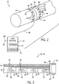
- FIG. 2 is an illustration of an embodiment of the welding system 10 having a temperature sensor belt.
- the workpiece 28 has a joint 30 where joining (e.g., welding) is to be performed.
- a temperature sensor belt 32 is positioned adjacent to the joint 30 to detect one or more temperatures of the workpiece 28 before, during, and/or after the joint 30 is welded.
- the temperature sensor belt 32 may be positioned within one to four inches from the joint 30, in certain embodiments.
- a second temperature sensor belt 34 is positioned adjacent to the joint 30, on an opposite side of the joint 30 relative to the temperature sensor belt 32.
- the temperature sensor belts 32 and 34 are substantially identical. While two temperature sensor belts 32 and 34 are illustrated, the welding system 10 may include 1, 2, 3, 4, 5, or more temperature sensor belts.
- two or more temperature sensor belts may be adjacent to one another on one side of the joint 30.
- the temperature sensor belts 32 and 34 may be formed from any suitable material that enables the belts 32 and 34 to wrap around (e.g., surround the external surface of) the workpiece 28, such as an elastic material, a flexible material, a heat resistant material, a cloth, a material having hook and loop fasteners (e.g., VelcroTM), and so forth. While the workpiece 28 has a circular external surface in the illustrated embodiment, in other embodiments, the workpiece 28 may have an external surface that is triangular, square, rectangular, flat, or any other standard or non-standard shape of exterior surface.
- two or more temperature sensor belts 32 and 34 may be connected in any suitable configuration to enable temperature measurements of any shape joint 30. For example, two or more temperature sensor belts 32 and 34 may be connected together serially.
- the temperature sensor belts 32, 34 include temperature sensors 36 attached to, installed in, installed on, and/or otherwise coupled thereto.
- the temperature sensors 36 may be attached to the temperature sensor belts 32, 34 so that the temperature sensors 36 contact the surface of the workpiece 28 (e.g., exterior surface, interior surface, or the temperature sensors may detect a temperature via conduction with the temperature sensor belts 32, 34.
- the temperature sensors 36 may detect a temperature without contacting the surface of the workpiece 28.
- the temperature sensors 36 may be any suitable devices that can provide indications that correspond to temperatures.
- one or more of the temperature sensors 36 may be a thermocouple, a bimetallic switch, a resistance temperature detector (RTD), a thermistor, a wax motor (e.g., actuator device suitable for converting thermal-to-mechanical energy via phase change behavior of waxes), and/or an infrared sensor.
- the indication representative of a temperature of the workpiece 28 may include a signal, such as a voltage signal, a current signal, a wireless, signal, a magnetic signal and so on.
- the indication may additionally or alternatively be a data packet or packets, or other indications that may include numbers, text, or a combination thereof.
- the temperature sensors 36 are configured to communicate with another device by using a cable 38. Moreover, in other embodiments, the temperature sensors 36 may provide indications (e.g., data or signals) that correspond to temperatures using wired and/or wireless communication.
- a data receiver 40 may receive the indications from the temperature sensors 36 via the cable 38.
- the data receiver 40 may be a stand alone device, or may be incorporated into a computer system, welding power supply (e.g., the power supply 12 illustrated in FIG. 1 ), or any suitable device, including cloud-based devices (e.g., servers accessible as cloud-based services).
- the data receiver 40 may include one or more storage devices 42 for storing the indications from the temperature sensors 36.
- the one or more storage devices 42 may include ROM, flash memory, a hard drive, or any other suitable optical, magnetic, or solid-state storage medium, or a combination thereof.
- the one or more storage devices 42 may store data (e.g., indications from the temperature sensors 36, temperature data, etc.), instructions (e.g., software or firmware for determining temperatures, etc.), and any other suitable data.
- the data receiver 40 may include one or more processors 43 for processing the indications from the temperature sensors 36, such as for converting indications to temperature data.
- the data receiver 40 may receive the indications from the temperature sensors 36 and may provide the indications to another device, without storing the indications.
- the data receiver 40 may function as a pass-through device where the indications from the temperature sensors 36 are provided to a network device, a storage device, a server, and/or any other suitable device for storage and/or processing (e.g., an Internet server, Cloud storage, etc.).
- the temperature sensor belts 32, 34 may also include one or more temperature sensors 44 configured to communicate using wireless signals 46.
- the data receiver 40 may be configured to receive wireless signals 48 for storing and/or processing the indications from the wireless temperature sensor 44.
- the wireless temperature sensor 44 may be a thermocouple, a bimetallic switch, a resistance temperature detector (RTD), a thermistor, a wax motor, and/or an infrared sensor, with a wireless module (e.g., BluetoothTM module, WiFi module, mesh networking module) suitable for transmitting wireless signals.
- the wireless temperature sensor 44 may also communicate using wired communication.
- the workpiece 28 may be configured to rotate during a welding operation.
- the wireless temperature sensor 44 may be used so that temperature sensor leads do not wrap around the workpiece 28.
- the belts 32, 34 may be partially disposed onto the workpiece 28. For example, only a portion of the belts 32, 34 may be positioned to take temperature readings of the workpiece 28. Because of the flexibility of the belts 32, 34, the belts 32, 34 may be positioned on the workpiece 28 to provide for curved belts 32, 34 (e.g., s-curves or any other curves), and/or to encircle certain joints in use. Further, in workpieces 28 of larger sizes, the belts 32, 34 may not completely surround the larger workpiece 28 but may only take readings of certain portions of the workpiece 28.
- the belts 32, 34 may be additionally disposed on inside portions of the workpiece 28, such as inside of a pipe.
- the belts 32, 34 may include magnetic layers or attachment points (e.g., magnets disposed on the belts 32, 34) suitable for magnetically attaching the belts 32, 34 onto the workpiece 28.
- the belts 32, 34 may be clamped inside or outside portions of the workpiece 28.
- the temperature sensor belts 32, 34 may also include a wireless transmitter/receiver system 50.
- the wireless system 50 may receive indications that correspond to temperatures from the temperature sensors 36 and 44 coupled to the temperature sensor belts 32, 34.
- the wireless system 50 may be electrically coupled to the temperature sensors 36, 44 of the temperature sensor belts 32, 34 and/or receive wireless signals from the wireless temperature sensors 44 of the temperature sensor belts 32, 34.
- the wireless system 50 may include a battery to power the temperature sensors 36, 44.
- the wireless system 50 provides wireless signals 52 that may be received by the data receiver 40.
- temperatures of the workpiece 28 may be detected and/or monitored. Accordingly, a quality of a weld performed on the joint 30 may be determined and/or controlled.
- FIG. 3 is a cross-sectional view of an example of a temperature sensor belt, not belonging to the invention.
- the temperature sensor belts 32, 34 may include an insulative layer 54.
- the insulative layer 54 is configured to thermally insulate one or more sides of the temperature sensors 36, 44 that are not arranged to contact the workpiece 28, such as to insulate the temperature sensors 36, 44 from direct heat produced by a welding operation.
- the insulative layer 54 may be configured to protect the temperature sensors 36, 44 and/or improve the accuracy of detected temperatures.
- the insulative layer 54 may be formed from any suitable material, such as a polymer based material, a cloth, a fabric, and so forth.
- connectors 56 are disposed in the insulative layer 54 to facilitate electrically coupling temperature sensor leads 58 to the temperature sensors 36. Furthermore, the temperature sensor leads 58 are disposed in the insulative layer 54.
- the temperature sensor belts 32, 34 may include a connector 60 that couples the temperature sensor leads 58 to the wireless system 50. As illustrated, the wireless system 50 may communicate wirelessly using the wireless signals 52 and/or the wireless system 50 may communicate using a wired connection coupled to the wireless system 50 via a connector 62. Accordingly, the leads 58 may be communicatively coupled to an external device, such as to the power supply 12.
- the connector 62 may be a 90° connector to facilitate coupling to the external device. In other embodiments, the connector 62 may be angled at any angle, including parallel to the belts 32, 34.
- the temperature sensor belts 32, 34 may include a support layer 64 configured to provide support to the insulative layer 54 and/or the temperature sensors 36, 44.
- the support layer 64 may include a protective material to protect the insulative layer 54 and/or the temperature sensors 36, 44 from abrasion and impact with welding spatter and/or other objects.
- the support layer 64 may be formed from any suitable material, such as a flexible material, a metal, a metal alloy, a heat resistive material, a polymeric material, and so forth.
- the support layer 64 may be formed from a braided metal (e.g., braided copper).
- the temperature sensor belts 32, 34 may also include indicators 66 which may be disposed on a side of the support layer 64 opposite the temperature sensors 36, and that may receive an indication (e.g., visual and/or audio indication) representative of the temperature of the workpiece 28 from the temperature sensors 36 via leads 68.
- the visual indicators 66 may provide a visual indication of a temperature or feedback relating to a temperature, such as via a digital display.
- the visual indicators 66 may each include one or more light-emitting diodes (LEDs) configured to illuminate when a threshold temperature is passed (e.g., when the temperature is greater than 300 degrees Celsius, when the temperature is less than 350 degrees Celsius, etc.).
- LEDs light-emitting diodes
- the threshold temperature may be set by an operator, such as using the data receiver 40, the wireless system 50, via setting on the sensors 36, 44 (e.g., jumper settings) and so forth.
- the indication devices 66 may also be disposed on the power supply 12. Accordingly, the power supply 12 may additionally or alternatively indicate to the operator 18 if the operation on the workpiece 28 is proceeding as desired (e.g., at the desired temperature).
- FIG. 3 shows two layers 64 and 54
- the belts 32, 34 may include other layers 64, 54.
- additional protective layers 64 may be disposed on top of layer 54, below layer 54, or between layer 54.
- multiple insulation layers 54 may be used.
- Multiple layers 54 may be stacked on top of each other, and similarly, multiple layers 64 may be stacked on top of each other.
- various combinations of layers 54 and 64 may be used.
- the insulation layer 54 may only partially insulate the sensors 36.
- the layer 54 may be disposed to partially surround the sensors 36 rather than completely surround the sensors 36. In other example, the layer 54 may only insulate a portion of the sensors 36, such a side of the sensors 36 or a portion of the side of the sensor 36. It is also to be noted that multiple layers 64 and 54 may each include different materials. For example, one protective layer 64 may include metal while another protective layer 64 may include KevlarTM. Likewise, one layer 54 may include NomexTM while another layer 54 may include a polymeric composition.
- the temperature sensors 36, 44 may be positioned at predetermined locations along the temperature sensor belts 32, 34.
- the temperature sensors 36, 44 may be positioned (e.g., evenly spaced) at intervals such as every 15, 30, 45, 60 cm, or any other distance.
- a position of the temperature sensors 36, 44 may be adjustable.
- the temperature sensors 36, 44 may be positioned to be located around a circular pipe at intervals such as every 10, 30, or 90 degrees (e.g., 12:00, 3:00, 6:00, 9:00 positions as viewed on a clock face).
- the temperature sensor belts 32, 34 may be manufactured for a specific sized pipe, or the temperature sensor belts 32, 34 may be adjustable.
- the temperature sensor belts 32, 34 may include a portion with hook and loop fasteners (e.g., VelcroTM portion), a locking portion, and/or a buckle portion used to adjust the size of the temperature sensor belts 32, 34.
- FIG. 4 is a perspective view of another example of the temperature sensor belt not belonging to the invention, with a housing for a temperature sensor.
- the temperature sensor belt 32 includes a band 70, which may be formed from a support material, a flexible material, a metal, or a high temperature polymer, for example.
- a temperature sensor housing 72 may be formed in (e.g., stamped, molded, brazed, riveted, etc.) the band 70 so that the temperature sensors 36, 44 may be inserted into and/or removed from the housing 72 (e.g., removable and replaceable sensor embodiments).
- the housing 72 may be formed to enable the temperature sensors 36, 44 to directly contact the workpiece 28 when the temperature sensor belts 32, 34 are attached to the workpiece 28, or the temperature sensors 36, 44 may detect temperatures conducted through the housing 72. That is, the housing 72 may be positioned, in use, to contact the workpiece 28. In certain embodiments, the housing 72 may enable detection of temperatures without the temperature sensors 36, 44 contacting the workpiece 28 (e.g., in embodiments where the sensors 36, 44 include an infrared sensor suitable for detecting temperature through infrared radiation transmitted from the workpiece 28).
- the housing 72 may include one or more openings disposed on a wall of the housing 72 abutting the workpiece 28 when in use, to enable the passage of infrared radiation into the sensors 36, 44. Furthermore, the housing 72 may function as a support layer and/or an insulative layer. In certain embodiments, the housing 72 may be manufactured to include a support layer separate from an insulative layer. Using the temperature sensor belts 32, 34, temperatures of the workpiece 28 may be detected and/or monitored. Accordingly, a quality of a weld performed on the joint 30 may be determined and/or controlled.
- FIG. 5 is a perspective view of an embodiment of the temperature sensor belts 32, 34 with a housing for a temperature sensor.
- the temperature sensor belts 32, 34 may include a strap 74 (e.g., support material, flexible material), such as an elastic strap, a strap having hook and loop fasteners (e.g., VelcroTM strap), a cloth strap, or any other suitable strap.
- Temperature sensor housings 76 are threaded onto the strap 74 and configured to hold temperature sensors 36, 44.
- the sensor housings 76 due at least in part to the threading technique used to mount the housings 76 onto the strap 74, may be repositionable housings 76.
- the welding operator 18 may reposition the housings 76 closer or further apart depending on the desired application (e.g., welding, cutting, grinding, induction heating, testing, and so forth).
- the housings 76 may also be removed from or added to the strap 74, as desired, to incorporate more or less temperature sensor readings for a particular application.
- FIG. 6 is a perspective view of an embodiment of the housing 76 of FIG. 5 having the temperature sensors 36, 44 inserted therein.
- the housing 76 includes openings 78 that enable the strap 74 to be threaded therethrough.
- the housing 76 may be formed from a metal (e.g., via stamping, CNC machining, molding) or a high temperature polymer (e.g., via molding).
- the housing 76 may be formed to enable the temperature sensors 36, 44 to directly contact the workpiece 28 through an opening 80 when the temperature sensor belts 32, 34 are attached to the workpiece 28.
- the temperature sensors 36, 44 may detect temperatures conducted through the housing 76 (e.g., through thermal conduction or thermal convection) or optically transmitted through the opening 80 (e.g., through infrared radiation) in the housing 76.
- the housing 76 may function as a support layer and/or an insulative layer. That is, by cradling the sensor 36, 44 as illustrated, the housing 76 may support the sensor 36, 44 and may also insulate the sensor 36, 44.
- the housing 76 may be manufactured to include a support layer separate from an insulative layer. Using the temperature sensor belts 32, 34, temperatures of the workpiece 28 may be detected and/or monitored. Accordingly, a quality of a weld performed on the joint 30 may be determined and/or controlled. Specifically, temperatures that the workpiece 28 is exposed to during the welding operation may be determined.
Landscapes
- Physics & Mathematics (AREA)
- General Physics & Mathematics (AREA)
- Engineering & Computer Science (AREA)
- Mechanical Engineering (AREA)
- General Engineering & Computer Science (AREA)
- Spectroscopy & Molecular Physics (AREA)
- Lining Or Joining Of Plastics Or The Like (AREA)
- Measuring Temperature Or Quantity Of Heat (AREA)
- Health & Medical Sciences (AREA)
- Life Sciences & Earth Sciences (AREA)
- Chemical & Material Sciences (AREA)
- Analytical Chemistry (AREA)
- Biochemistry (AREA)
- General Health & Medical Sciences (AREA)
- Immunology (AREA)
- Pathology (AREA)
Claims (10)
- Temperatursensorband (32, 34), Folgendes umfassend:- mehrere Temperatursensoren (36, 44), die auf dem Sensorband (32, 34) angeordnet sind, wobei die mehreren Temperatursensoren (36, 44) eingerichtet sind, um eine Angabe bereitzustellen, die für eine Temperatur eines Werkstücks (28) repräsentativ ist;- mehrere Gehäuse (72, 76), in die jeweils ein Temperatursensor der mehreren Temperatursensoren (36, 44) eingerichtet ist, um eingefügt zu werden, wobei jedes Gehäuse der mehreren Gehäuse ein isolierendes Material umfasst, das die mehreren Temperatursensoren (36, 44) umgibt und das eingerichtet ist, um die Seiten der mehreren Temperatursensoren (36, 44), die nicht angeordnet sind, um das Werkstück (28) zu kontaktieren, thermisch zu isolieren, und- ein Trägermaterial, das eingerichtet ist, um über den mehreren Temperatursensoren (36, 44) angeordnet zu sein, wenn die mehreren Temperatursensoren (36, 44) in die mehreren Gehäuse (72, 76) eingefügt sind, wobei das Trägermaterial eingerichtet ist, um die mehreren Temperatursensoren (36, 44) zu tragen,wobei das Sensorband (32, 34) einen Riemen (74) des Trägermaterials umfasst,
wobei jeder der mehreren Temperatursensoren (36, 44) eingerichtet ist, um die Angabe bereitzustellen, die für die Temperatur des Werkstücks (28) repräsentativ ist, während eine Schweißoperation, eine Schneidoperation, eine Schleifoperation oder eine Induktionsheizoperation an dem Werkstück (28) durchgeführt wird, dadurch gekennzeichnet, dass die mehreren Sensorgehäuse (72, 76) eingerichtet sind, um auf den Riemen (74) geschraubt zu werden, um die mehreren Sensorgehäuse (72, 76) repositionierbar und entfernbar auf dem Riemen (74) zu befestigen,
wobei jedes Gehäuse der mehreren Sensorgehäuse (72, 76) Öffnungen (78) umfasst, die ermöglichen, dass der Riemen dadurch verschraubt wird,
wobei das Temperatursensorband (32, 34) eingerichtet ist, um seriell mit mindestens einem zusätzlichen Temperatursensorband (32, 34) zusammen verbunden zu sein. - Temperatursensorband nach Anspruch 1,
wobei die mehreren Temperatursensoren (36, 44) mindestens einen Infrarotsensor, ein Thermoelement, einen Bimetallschalter, einen Widerstandstemperaturdetektor (RTD), einen Thermistor, einen Dehnstoffelementthermostaten oder eine Kombination davon umfassen. - Temperatursensorband nach Anspruch 1 oder 2,
wobei das Trägermaterial ein flexibles Material umfasst. - Temperatursensorband nach einem der vorhergehenden Ansprüche, ein drahtloses System (50) umfassend, das durch das Trägermaterial unterstützt wird und mit mindestens einem der mehreren Temperatursensoren (36, 44) kommunikativ gekoppelt ist, wobei das Temperatursensorband (32, 34) eingerichtet ist, um drahtlos über das drahtlose System (50) zu kommunizieren.
- Temperatursensorband nach einem der vorhergehenden Ansprüche,
wobei mindestens einer der mehreren Temperatursensoren (36, 44) einen drahtlosen Temperatursensor (44) umfasst, der eingerichtet ist, um die Angabe drahtlos zu übertragen, die für die Temperatur des Werkstücks (28) repräsentativ ist. - Temperatursensorband nach einem der vorhergehenden Ansprüche,
wobei das Temperatursensorband (32, 34) eine Länge aufweist, die eingerichtet ist, um mindestens teilweise eine äußere Oberfläche des Werkstücks (28) zu umgeben. - Temperatursensorband nach Anspruch 6,
wobei das Werkstück (28) ein Rohr umfasst. - Temperatursensorband nach einem der vorhergehenden Ansprüche,
wobei jeder Temperatursensor (36, 44) der mehreren Temperatursensoren unregelmäßig von einem jeweiligen benachbarten Temperatursensor (36, 44) beabstandet ist. - Temperatursensorband nach einem der vorhergehenden Ansprüche, Temperatursensoranschlüsse (58) umfassend, die eingerichtet sind, um kommunikativ mit einer externen Vorrichtung gekoppelt zu sein.
- Temperatursensorband nach Anspruch 9,
wobei jeder Temperatursensor (36, 44) der mehreren Temperatursensoren eingerichtet ist, um die Angaben einem drahtlosen Sender bereitzustellen.
Applications Claiming Priority (3)
| Application Number | Priority Date | Filing Date | Title |
|---|---|---|---|
| US201361821959P | 2013-05-10 | 2013-05-10 | |
| US14/258,987 US9733130B2 (en) | 2013-05-10 | 2014-04-22 | Temperature sensor belt |
| PCT/US2014/036170 WO2014182526A1 (en) | 2013-05-10 | 2014-04-30 | Temperature sensor belt |
Publications (2)
| Publication Number | Publication Date |
|---|---|
| EP2994729A1 EP2994729A1 (de) | 2016-03-16 |
| EP2994729B1 true EP2994729B1 (de) | 2020-11-11 |
Family
ID=51864766
Family Applications (1)
| Application Number | Title | Priority Date | Filing Date |
|---|---|---|---|
| EP14728745.2A Active EP2994729B1 (de) | 2013-05-10 | 2014-04-30 | Temperatursensorband |
Country Status (5)
| Country | Link |
|---|---|
| US (2) | US9733130B2 (de) |
| EP (1) | EP2994729B1 (de) |
| CN (2) | CN109974871B (de) |
| CA (1) | CA2902583C (de) |
| WO (1) | WO2014182526A1 (de) |
Families Citing this family (25)
| Publication number | Priority date | Publication date | Assignee | Title |
|---|---|---|---|---|
| US9146172B2 (en) * | 2011-01-03 | 2015-09-29 | Sentinel Hydrosolutions, Llc | Non-invasive thermal dispersion flow meter with chronometric monitor for fluid leak detection |
| FR3041467B1 (fr) * | 2015-09-18 | 2022-01-21 | Electricite De France | Ceinture de mesure de temperature d'un objet |
| FR3041429B1 (fr) * | 2015-09-18 | 2020-03-27 | Electricite De France | Ceinture de mesure de grandeurs physiques d'un objet |
| FR3057664B1 (fr) * | 2016-10-19 | 2018-10-19 | Vallourec Oil And Gas France | Dispositif de determination de la qualite d'assemblage de composants tubulaires filetes |
| CN106768691A (zh) * | 2016-12-27 | 2017-05-31 | 苏州市宏业灯具设备有限公司 | 一种蒸汽发生器用蒸汽泄露检测装置 |
| US10822995B2 (en) * | 2017-01-17 | 2020-11-03 | The Boeing Company | Flexible band electrical component mounts and methods |
| US20190320244A1 (en) * | 2018-04-16 | 2019-10-17 | Nidec Motor Corporation | Sensor module system |
| US11287330B2 (en) * | 2018-08-14 | 2022-03-29 | Watlow Electric Manufacturing Company | Low profile surface temperature sensor |
| CN110849497B (zh) * | 2018-08-20 | 2026-03-27 | 深圳市敏杰电子科技有限公司 | 薄膜温度传感器的安装结构以及温度传感装置 |
| US10899529B2 (en) * | 2018-12-06 | 2021-01-26 | Integreon Global, Inc. | Thermal insulation box with temperature and humidity sensors |
| US10962272B2 (en) * | 2018-12-06 | 2021-03-30 | Tcp Reliable, Inc. | Thermal insulation box with cooling mechanism |
| CN109752111A (zh) * | 2019-01-23 | 2019-05-14 | 杭州嘉诚机械有限公司 | 简易便携式减速机专用轴温检测模块及检测方法 |
| DE102019124604A1 (de) * | 2019-09-12 | 2021-03-18 | Endress + Hauser Wetzer Gmbh + Co. Kg | Nicht invasives Thermometer |
| DE102019124605A1 (de) * | 2019-09-12 | 2021-03-18 | Endress + Hauser Wetzer Gmbh + Co. Kg | Nicht invasives Thermometer |
| WO2021197921A1 (de) * | 2020-03-30 | 2021-10-07 | Sma Solar Technology Ag | Vorrichtung zur temperaturmessung und vorrichtung zur stromermittlung |
| CN115835829B (zh) * | 2020-04-02 | 2025-12-12 | 直观外科手术操作公司 | 用于器械使用记录的设备、记录器械再处理事件的设备及相关系统和方法 |
| US11408778B2 (en) | 2020-07-21 | 2022-08-09 | Apple Inc. | Temperature gradient sensing in portable electronic devices |
| US11771329B2 (en) * | 2020-09-24 | 2023-10-03 | Apple Inc. | Flexible temperature sensing devices for body temperature sensing |
| CN112556865A (zh) * | 2020-12-09 | 2021-03-26 | 翟国强 | 一种锅炉管道内水温检测装置 |
| WO2022245228A1 (en) * | 2021-05-18 | 2022-11-24 | Bpe Sp. Z O.O. | System for measuring temperature distribution in heating network and method of monitoring heating network |
| DE102021117224A1 (de) | 2021-07-05 | 2023-01-05 | Dr. Ing. H.C. F. Porsche Aktiengesellschaft | Anordnung zur Temperaturmessung an einer Batteriezelle sowie Batteriezelle mit einer solchen Anordnung |
| US12575739B2 (en) | 2021-09-21 | 2026-03-17 | Apple Inc. | Distributed sensor network for measurement of biometric parameter |
| US20230265959A1 (en) * | 2022-02-21 | 2023-08-24 | Todd A. Volker | Method and apparatus for reinforcing piping and installing a pipe adapter |
| US12523537B2 (en) | 2023-08-11 | 2026-01-13 | Saudi Arabian Oil Company | Removable sensors system with color indicator for temperature monitoring |
| EP4592659A1 (de) * | 2024-01-29 | 2025-07-30 | Alejandro Torres González | Vorrichtung zur beurteilung des zustandes einer isolierung |
Citations (2)
| Publication number | Priority date | Publication date | Assignee | Title |
|---|---|---|---|---|
| DE20216024U1 (de) * | 2002-10-17 | 2003-01-16 | Sick AG, 79183 Waldkirch | Befestigungsvorrichtung für Sensoren |
| CN202255656U (zh) * | 2011-10-11 | 2012-05-30 | 上海电气核电设备有限公司 | 筒体热处理热电偶固定工装装置 |
Family Cites Families (36)
| Publication number | Priority date | Publication date | Assignee | Title |
|---|---|---|---|---|
| US2737050A (en) * | 1953-05-27 | 1956-03-06 | George W Moninger | Thermometer receptacle for attachment to pipes |
| US3983753A (en) * | 1975-09-29 | 1976-10-05 | The United States Of America As Represented By The United States National Aeronautics And Space Administration | Thermistor holder for skin temperature measurements |
| DE3126931A1 (de) | 1981-07-08 | 1983-02-03 | Ultrakust Gerätebau GmbH & Co KG, 8375 Ruhmannsfelden | Haltevorrichtung fuer einen temperaturfuehler |
| DE3225921C2 (de) * | 1982-07-10 | 1985-10-24 | Barlian, Reinhold, Dipl.-Ing.(FH), 6990 Bad Mergentheim | Überwachungseinrichtung |
| US4569355A (en) * | 1982-05-28 | 1986-02-11 | Hemodynamics Technology, Inc. | Method and apparatus for monitoring and diagnosing peripheral blood flow |
| FR2561382A1 (fr) | 1984-03-16 | 1985-09-20 | Chauvin Arnoux Sa | Capteur thermometrique pour mesure de temperature de surface |
| US4699519A (en) * | 1985-04-08 | 1987-10-13 | Performance Technology, Inc. | Grain temperature monitor |
| CN2042193U (zh) * | 1988-06-15 | 1989-08-02 | 张士洪 | 非插入式铂电阻温度计 |
| US5255979A (en) * | 1993-02-01 | 1993-10-26 | Ferrari R Keith | Medical temperature probe cover |
| US5980102A (en) * | 1994-06-20 | 1999-11-09 | Columbia Gas Of Ohio | Method for measuring physical characteristics in a pipeline without tapping |
| US5632919A (en) * | 1996-01-25 | 1997-05-27 | T.G.M., Inc. | Temperature controlled insulation system |
| AU1198100A (en) * | 1998-09-23 | 2000-04-10 | Keith Bridger | Physiological sensing device |
| JP2000205967A (ja) * | 1999-01-11 | 2000-07-28 | Mitsubishi Heavy Ind Ltd | 熱電対及び同熱電対の取付構造 |
| DE19953654A1 (de) * | 1999-11-08 | 2001-05-23 | Pink Gmbh Vakuumtechnik | Verfahren und Vorrichtung zur Herstellung einer Lotverbindung |
| AU2363502A (en) * | 2000-10-24 | 2002-05-06 | Saipem Spa | Method and apparatus for welding pipes together |
| ITPN20010003U1 (it) * | 2001-01-25 | 2002-07-25 | Sipa Spa | Dispositivo per il rilevamento di variazioni di temperatura con alloggiamento per il sensore |
| CA2460290A1 (en) * | 2001-11-01 | 2003-05-08 | Bliss C. Carkhuff | Techniques for monitoring health of vessels containing fluids |
| FR2833346B1 (fr) | 2001-12-06 | 2004-07-02 | Jules Richard Instr Sa | Dispositif de mesure de la temperature d'un fluide dans un conduit et systeme de controle utilisant un tel dispositif |
| EP1849013B1 (de) * | 2005-02-01 | 2011-11-30 | The Timken Company | Lager mit am käfig angebrachten sensoren |
| US7299963B2 (en) * | 2005-05-23 | 2007-11-27 | Illinois Tool Works Inc. | Temperature sensor for combustion nailer |
| US20100036277A1 (en) * | 2006-07-06 | 2010-02-11 | John Austin | Animal temperature monitor and monitoring method |
| CN201110789Y (zh) * | 2007-11-15 | 2008-09-03 | 王德文 | 一种钢轨焊接温度测控装置 |
| US20090232183A1 (en) * | 2008-03-13 | 2009-09-17 | General Electric Company | System and method to measure temperature in an electric machine |
| WO2010055455A1 (en) * | 2008-11-11 | 2010-05-20 | Koninklijke Philips Electronics N.V. | Medical device comprising a probe for measuring temperature data in a patient's tissue |
| DE102009003848A1 (de) | 2009-04-29 | 2010-11-04 | Infratec Ag | Temperaturkontrolleinrichtung |
| CN201464070U (zh) * | 2009-09-07 | 2010-05-12 | 瓮福(集团)有限责任公司 | 一种测量管道表面温度的热电偶 |
| US9494272B2 (en) * | 2009-10-19 | 2016-11-15 | Embedded Energy Technology, Llc | Insulation jacket and insulation jacket system |
| JP5513208B2 (ja) * | 2010-03-30 | 2014-06-04 | 高砂熱学工業株式会社 | 配管表面多点温度センサ及び流量計測用管 |
| US11072035B2 (en) * | 2010-05-21 | 2021-07-27 | Illinois Tool Works Inc. | Auxiliary welding heating system |
| WO2011150323A2 (en) * | 2010-05-28 | 2011-12-01 | Neurodx Development, Llc | Real time csf flow measurement system & method |
| KR101005692B1 (ko) * | 2010-06-14 | 2011-01-05 | 강성원 | 기능성 복대 |
| CN201772935U (zh) * | 2010-07-01 | 2011-03-23 | 卢映桦 | 婴儿体温监测仪 |
| CN202271525U (zh) * | 2011-07-28 | 2012-06-13 | 广东联塑科技实业有限公司 | 一种带温控的管件焊接机及其温控系统 |
| US9341535B2 (en) * | 2012-02-03 | 2016-05-17 | Kulite Semiconductor Products, Inc. | Pressure belt comprising replaceable sensing elements |
| US20140161151A1 (en) * | 2012-12-12 | 2014-06-12 | John Proctor | Line & pipe flexible temperature sensor assembly |
| US20140299595A1 (en) * | 2013-04-09 | 2014-10-09 | Illinois Tool Works Inc. | System and method for holding a temperature probe in an induction heating system |
-
2014
- 2014-04-22 US US14/258,987 patent/US9733130B2/en active Active
- 2014-04-30 CN CN201910163813.5A patent/CN109974871B/zh not_active Expired - Fee Related
- 2014-04-30 WO PCT/US2014/036170 patent/WO2014182526A1/en not_active Ceased
- 2014-04-30 CA CA2902583A patent/CA2902583C/en active Active
- 2014-04-30 CN CN201480023562.6A patent/CN105143840B/zh not_active Expired - Fee Related
- 2014-04-30 EP EP14728745.2A patent/EP2994729B1/de active Active
-
2017
- 2017-08-03 US US15/668,403 patent/US10458855B2/en active Active
Patent Citations (2)
| Publication number | Priority date | Publication date | Assignee | Title |
|---|---|---|---|---|
| DE20216024U1 (de) * | 2002-10-17 | 2003-01-16 | Sick AG, 79183 Waldkirch | Befestigungsvorrichtung für Sensoren |
| CN202255656U (zh) * | 2011-10-11 | 2012-05-30 | 上海电气核电设备有限公司 | 筒体热处理热电偶固定工装装置 |
Also Published As
| Publication number | Publication date |
|---|---|
| WO2014182526A1 (en) | 2014-11-13 |
| CA2902583C (en) | 2018-11-06 |
| US10458855B2 (en) | 2019-10-29 |
| CN105143840A (zh) | 2015-12-09 |
| CN105143840B (zh) | 2019-03-29 |
| CN109974871B (zh) | 2021-11-12 |
| CA2902583A1 (en) | 2014-11-13 |
| EP2994729A1 (de) | 2016-03-16 |
| CN109974871A (zh) | 2019-07-05 |
| US20140334517A1 (en) | 2014-11-13 |
| US9733130B2 (en) | 2017-08-15 |
| US20170328784A1 (en) | 2017-11-16 |
Similar Documents
| Publication | Publication Date | Title |
|---|---|---|
| US10458855B2 (en) | Temperature sensor belt | |
| US12070821B2 (en) | Welding system for determining a quality of a welding operation | |
| EP3010677B1 (de) | System und verfahren zur bestimmung einer schweisslaufgeschwindigkeit | |
| CA2902580C (en) | Data acquisition using a purge plug | |
| US20160144445A1 (en) | Welding torch with a temperature measurement device | |
| EP2994730B1 (de) | Drehbare temperaturmessvorrichtung | |
| KR20230103564A (ko) | 와이어 피더를 이용한 용접 작업관리 시스템 | |
| EP2547484B1 (de) | Kondensator-leiterplatten-schnittstelle zum schweissen von systemkomponenten |
Legal Events
| Date | Code | Title | Description |
|---|---|---|---|
| PUAI | Public reference made under article 153(3) epc to a published international application that has entered the european phase |
Free format text: ORIGINAL CODE: 0009012 |
|
| 17P | Request for examination filed |
Effective date: 20150825 |
|
| AK | Designated contracting states |
Kind code of ref document: A1 Designated state(s): AL AT BE BG CH CY CZ DE DK EE ES FI FR GB GR HR HU IE IS IT LI LT LU LV MC MK MT NL NO PL PT RO RS SE SI SK SM TR |
|
| AX | Request for extension of the european patent |
Extension state: BA ME |
|
| DAX | Request for extension of the european patent (deleted) | ||
| STAA | Information on the status of an ep patent application or granted ep patent |
Free format text: STATUS: EXAMINATION IS IN PROGRESS |
|
| 17Q | First examination report despatched |
Effective date: 20170301 |
|
| GRAP | Despatch of communication of intention to grant a patent |
Free format text: ORIGINAL CODE: EPIDOSNIGR1 |
|
| STAA | Information on the status of an ep patent application or granted ep patent |
Free format text: STATUS: GRANT OF PATENT IS INTENDED |
|
| RIC1 | Information provided on ipc code assigned before grant |
Ipc: F27D 21/00 20060101ALI20200508BHEP Ipc: G01K 1/14 20060101AFI20200508BHEP |
|
| INTG | Intention to grant announced |
Effective date: 20200612 |
|
| GRAS | Grant fee paid |
Free format text: ORIGINAL CODE: EPIDOSNIGR3 |
|
| GRAA | (expected) grant |
Free format text: ORIGINAL CODE: 0009210 |
|
| STAA | Information on the status of an ep patent application or granted ep patent |
Free format text: STATUS: THE PATENT HAS BEEN GRANTED |
|
| AK | Designated contracting states |
Kind code of ref document: B1 Designated state(s): AL AT BE BG CH CY CZ DE DK EE ES FI FR GB GR HR HU IE IS IT LI LT LU LV MC MK MT NL NO PL PT RO RS SE SI SK SM TR |
|
| REG | Reference to a national code |
Ref country code: GB Ref legal event code: FG4D |
|
| REG | Reference to a national code |
Ref country code: CH Ref legal event code: EP |
|
| REG | Reference to a national code |
Ref country code: AT Ref legal event code: REF Ref document number: 1333937 Country of ref document: AT Kind code of ref document: T Effective date: 20201115 |
|
| REG | Reference to a national code |
Ref country code: DE Ref legal event code: R096 Ref document number: 602014072251 Country of ref document: DE |
|
| REG | Reference to a national code |
Ref country code: IE Ref legal event code: FG4D |
|
| REG | Reference to a national code |
Ref country code: NL Ref legal event code: MP Effective date: 20201111 |
|
| REG | Reference to a national code |
Ref country code: AT Ref legal event code: MK05 Ref document number: 1333937 Country of ref document: AT Kind code of ref document: T Effective date: 20201111 |
|
| PG25 | Lapsed in a contracting state [announced via postgrant information from national office to epo] |
Ref country code: PT Free format text: LAPSE BECAUSE OF FAILURE TO SUBMIT A TRANSLATION OF THE DESCRIPTION OR TO PAY THE FEE WITHIN THE PRESCRIBED TIME-LIMIT Effective date: 20210311 Ref country code: NO Free format text: LAPSE BECAUSE OF FAILURE TO SUBMIT A TRANSLATION OF THE DESCRIPTION OR TO PAY THE FEE WITHIN THE PRESCRIBED TIME-LIMIT Effective date: 20210211 Ref country code: FI Free format text: LAPSE BECAUSE OF FAILURE TO SUBMIT A TRANSLATION OF THE DESCRIPTION OR TO PAY THE FEE WITHIN THE PRESCRIBED TIME-LIMIT Effective date: 20201111 Ref country code: RS Free format text: LAPSE BECAUSE OF FAILURE TO SUBMIT A TRANSLATION OF THE DESCRIPTION OR TO PAY THE FEE WITHIN THE PRESCRIBED TIME-LIMIT Effective date: 20201111 Ref country code: GR Free format text: LAPSE BECAUSE OF FAILURE TO SUBMIT A TRANSLATION OF THE DESCRIPTION OR TO PAY THE FEE WITHIN THE PRESCRIBED TIME-LIMIT Effective date: 20210212 |
|
| PG25 | Lapsed in a contracting state [announced via postgrant information from national office to epo] |
Ref country code: LV Free format text: LAPSE BECAUSE OF FAILURE TO SUBMIT A TRANSLATION OF THE DESCRIPTION OR TO PAY THE FEE WITHIN THE PRESCRIBED TIME-LIMIT Effective date: 20201111 Ref country code: SE Free format text: LAPSE BECAUSE OF FAILURE TO SUBMIT A TRANSLATION OF THE DESCRIPTION OR TO PAY THE FEE WITHIN THE PRESCRIBED TIME-LIMIT Effective date: 20201111 Ref country code: PL Free format text: LAPSE BECAUSE OF FAILURE TO SUBMIT A TRANSLATION OF THE DESCRIPTION OR TO PAY THE FEE WITHIN THE PRESCRIBED TIME-LIMIT Effective date: 20201111 Ref country code: IS Free format text: LAPSE BECAUSE OF FAILURE TO SUBMIT A TRANSLATION OF THE DESCRIPTION OR TO PAY THE FEE WITHIN THE PRESCRIBED TIME-LIMIT Effective date: 20210311 Ref country code: AT Free format text: LAPSE BECAUSE OF FAILURE TO SUBMIT A TRANSLATION OF THE DESCRIPTION OR TO PAY THE FEE WITHIN THE PRESCRIBED TIME-LIMIT Effective date: 20201111 Ref country code: BG Free format text: LAPSE BECAUSE OF FAILURE TO SUBMIT A TRANSLATION OF THE DESCRIPTION OR TO PAY THE FEE WITHIN THE PRESCRIBED TIME-LIMIT Effective date: 20210211 |
|
| REG | Reference to a national code |
Ref country code: LT Ref legal event code: MG9D |
|
| PG25 | Lapsed in a contracting state [announced via postgrant information from national office to epo] |
Ref country code: HR Free format text: LAPSE BECAUSE OF FAILURE TO SUBMIT A TRANSLATION OF THE DESCRIPTION OR TO PAY THE FEE WITHIN THE PRESCRIBED TIME-LIMIT Effective date: 20201111 |
|
| PG25 | Lapsed in a contracting state [announced via postgrant information from national office to epo] |
Ref country code: SK Free format text: LAPSE BECAUSE OF FAILURE TO SUBMIT A TRANSLATION OF THE DESCRIPTION OR TO PAY THE FEE WITHIN THE PRESCRIBED TIME-LIMIT Effective date: 20201111 Ref country code: RO Free format text: LAPSE BECAUSE OF FAILURE TO SUBMIT A TRANSLATION OF THE DESCRIPTION OR TO PAY THE FEE WITHIN THE PRESCRIBED TIME-LIMIT Effective date: 20201111 Ref country code: LT Free format text: LAPSE BECAUSE OF FAILURE TO SUBMIT A TRANSLATION OF THE DESCRIPTION OR TO PAY THE FEE WITHIN THE PRESCRIBED TIME-LIMIT Effective date: 20201111 Ref country code: CZ Free format text: LAPSE BECAUSE OF FAILURE TO SUBMIT A TRANSLATION OF THE DESCRIPTION OR TO PAY THE FEE WITHIN THE PRESCRIBED TIME-LIMIT Effective date: 20201111 Ref country code: EE Free format text: LAPSE BECAUSE OF FAILURE TO SUBMIT A TRANSLATION OF THE DESCRIPTION OR TO PAY THE FEE WITHIN THE PRESCRIBED TIME-LIMIT Effective date: 20201111 Ref country code: SM Free format text: LAPSE BECAUSE OF FAILURE TO SUBMIT A TRANSLATION OF THE DESCRIPTION OR TO PAY THE FEE WITHIN THE PRESCRIBED TIME-LIMIT Effective date: 20201111 |
|
| REG | Reference to a national code |
Ref country code: DE Ref legal event code: R097 Ref document number: 602014072251 Country of ref document: DE |
|
| PG25 | Lapsed in a contracting state [announced via postgrant information from national office to epo] |
Ref country code: DK Free format text: LAPSE BECAUSE OF FAILURE TO SUBMIT A TRANSLATION OF THE DESCRIPTION OR TO PAY THE FEE WITHIN THE PRESCRIBED TIME-LIMIT Effective date: 20201111 |
|
| PLBE | No opposition filed within time limit |
Free format text: ORIGINAL CODE: 0009261 |
|
| STAA | Information on the status of an ep patent application or granted ep patent |
Free format text: STATUS: NO OPPOSITION FILED WITHIN TIME LIMIT |
|
| 26N | No opposition filed |
Effective date: 20210812 |
|
| PG25 | Lapsed in a contracting state [announced via postgrant information from national office to epo] |
Ref country code: AL Free format text: LAPSE BECAUSE OF FAILURE TO SUBMIT A TRANSLATION OF THE DESCRIPTION OR TO PAY THE FEE WITHIN THE PRESCRIBED TIME-LIMIT Effective date: 20201111 Ref country code: NL Free format text: LAPSE BECAUSE OF FAILURE TO SUBMIT A TRANSLATION OF THE DESCRIPTION OR TO PAY THE FEE WITHIN THE PRESCRIBED TIME-LIMIT Effective date: 20201111 |
|
| PG25 | Lapsed in a contracting state [announced via postgrant information from national office to epo] |
Ref country code: SI Free format text: LAPSE BECAUSE OF FAILURE TO SUBMIT A TRANSLATION OF THE DESCRIPTION OR TO PAY THE FEE WITHIN THE PRESCRIBED TIME-LIMIT Effective date: 20201111 Ref country code: MC Free format text: LAPSE BECAUSE OF FAILURE TO SUBMIT A TRANSLATION OF THE DESCRIPTION OR TO PAY THE FEE WITHIN THE PRESCRIBED TIME-LIMIT Effective date: 20201111 Ref country code: ES Free format text: LAPSE BECAUSE OF FAILURE TO SUBMIT A TRANSLATION OF THE DESCRIPTION OR TO PAY THE FEE WITHIN THE PRESCRIBED TIME-LIMIT Effective date: 20201111 |
|
| GBPC | Gb: european patent ceased through non-payment of renewal fee |
Effective date: 20210430 |
|
| PG25 | Lapsed in a contracting state [announced via postgrant information from national office to epo] |
Ref country code: LU Free format text: LAPSE BECAUSE OF NON-PAYMENT OF DUE FEES Effective date: 20210430 |
|
| REG | Reference to a national code |
Ref country code: BE Ref legal event code: MM Effective date: 20210430 |
|
| PG25 | Lapsed in a contracting state [announced via postgrant information from national office to epo] |
Ref country code: LI Free format text: LAPSE BECAUSE OF NON-PAYMENT OF DUE FEES Effective date: 20210430 Ref country code: CH Free format text: LAPSE BECAUSE OF NON-PAYMENT OF DUE FEES Effective date: 20210430 Ref country code: GB Free format text: LAPSE BECAUSE OF NON-PAYMENT OF DUE FEES Effective date: 20210430 Ref country code: FR Free format text: LAPSE BECAUSE OF NON-PAYMENT OF DUE FEES Effective date: 20210430 |
|
| PG25 | Lapsed in a contracting state [announced via postgrant information from national office to epo] |
Ref country code: IE Free format text: LAPSE BECAUSE OF NON-PAYMENT OF DUE FEES Effective date: 20210430 |
|
| PG25 | Lapsed in a contracting state [announced via postgrant information from national office to epo] |
Ref country code: IS Free format text: LAPSE BECAUSE OF FAILURE TO SUBMIT A TRANSLATION OF THE DESCRIPTION OR TO PAY THE FEE WITHIN THE PRESCRIBED TIME-LIMIT Effective date: 20210311 |
|
| PG25 | Lapsed in a contracting state [announced via postgrant information from national office to epo] |
Ref country code: BE Free format text: LAPSE BECAUSE OF NON-PAYMENT OF DUE FEES Effective date: 20210430 |
|
| PG25 | Lapsed in a contracting state [announced via postgrant information from national office to epo] |
Ref country code: HU Free format text: LAPSE BECAUSE OF FAILURE TO SUBMIT A TRANSLATION OF THE DESCRIPTION OR TO PAY THE FEE WITHIN THE PRESCRIBED TIME-LIMIT; INVALID AB INITIO Effective date: 20140430 |
|
| PG25 | Lapsed in a contracting state [announced via postgrant information from national office to epo] |
Ref country code: CY Free format text: LAPSE BECAUSE OF FAILURE TO SUBMIT A TRANSLATION OF THE DESCRIPTION OR TO PAY THE FEE WITHIN THE PRESCRIBED TIME-LIMIT Effective date: 20201111 |
|
| P01 | Opt-out of the competence of the unified patent court (upc) registered |
Effective date: 20230606 |
|
| PG25 | Lapsed in a contracting state [announced via postgrant information from national office to epo] |
Ref country code: MK Free format text: LAPSE BECAUSE OF FAILURE TO SUBMIT A TRANSLATION OF THE DESCRIPTION OR TO PAY THE FEE WITHIN THE PRESCRIBED TIME-LIMIT Effective date: 20201111 |
|
| PG25 | Lapsed in a contracting state [announced via postgrant information from national office to epo] |
Ref country code: TR Free format text: LAPSE BECAUSE OF FAILURE TO SUBMIT A TRANSLATION OF THE DESCRIPTION OR TO PAY THE FEE WITHIN THE PRESCRIBED TIME-LIMIT Effective date: 20201111 |
|
| PG25 | Lapsed in a contracting state [announced via postgrant information from national office to epo] |
Ref country code: MT Free format text: LAPSE BECAUSE OF FAILURE TO SUBMIT A TRANSLATION OF THE DESCRIPTION OR TO PAY THE FEE WITHIN THE PRESCRIBED TIME-LIMIT Effective date: 20201111 |
|
| PGFP | Annual fee paid to national office [announced via postgrant information from national office to epo] |
Ref country code: DE Payment date: 20250429 Year of fee payment: 12 |
|
| PGFP | Annual fee paid to national office [announced via postgrant information from national office to epo] |
Ref country code: IT Payment date: 20250422 Year of fee payment: 12 |