EP2993780A1 - Controller and map file conversion device - Google Patents
Controller and map file conversion device Download PDFInfo
- Publication number
- EP2993780A1 EP2993780A1 EP14791349.5A EP14791349A EP2993780A1 EP 2993780 A1 EP2993780 A1 EP 2993780A1 EP 14791349 A EP14791349 A EP 14791349A EP 2993780 A1 EP2993780 A1 EP 2993780A1
- Authority
- EP
- European Patent Office
- Prior art keywords
- map file
- data
- drive device
- stored
- address
- Prior art date
- Legal status (The legal status is an assumption and is not a legal conclusion. Google has not performed a legal analysis and makes no representation as to the accuracy of the status listed.)
- Withdrawn
Links
Images


Classifications
-
- B—PERFORMING OPERATIONS; TRANSPORTING
- B60—VEHICLES IN GENERAL
- B60L—PROPULSION OF ELECTRICALLY-PROPELLED VEHICLES; SUPPLYING ELECTRIC POWER FOR AUXILIARY EQUIPMENT OF ELECTRICALLY-PROPELLED VEHICLES; ELECTRODYNAMIC BRAKE SYSTEMS FOR VEHICLES IN GENERAL; MAGNETIC SUSPENSION OR LEVITATION FOR VEHICLES; MONITORING OPERATING VARIABLES OF ELECTRICALLY-PROPELLED VEHICLES; ELECTRIC SAFETY DEVICES FOR ELECTRICALLY-PROPELLED VEHICLES
- B60L3/00—Electric devices on electrically-propelled vehicles for safety purposes; Monitoring operating variables, e.g. speed, deceleration or energy consumption
- B60L3/12—Recording operating variables ; Monitoring of operating variables
-
- B—PERFORMING OPERATIONS; TRANSPORTING
- B60—VEHICLES IN GENERAL
- B60L—PROPULSION OF ELECTRICALLY-PROPELLED VEHICLES; SUPPLYING ELECTRIC POWER FOR AUXILIARY EQUIPMENT OF ELECTRICALLY-PROPELLED VEHICLES; ELECTRODYNAMIC BRAKE SYSTEMS FOR VEHICLES IN GENERAL; MAGNETIC SUSPENSION OR LEVITATION FOR VEHICLES; MONITORING OPERATING VARIABLES OF ELECTRICALLY-PROPELLED VEHICLES; ELECTRIC SAFETY DEVICES FOR ELECTRICALLY-PROPELLED VEHICLES
- B60L15/00—Methods, circuits, or devices for controlling the traction-motor speed of electrically-propelled vehicles
- B60L15/20—Methods, circuits, or devices for controlling the traction-motor speed of electrically-propelled vehicles for control of the vehicle or its driving motor to achieve a desired performance, e.g. speed, torque, programmed variation of speed
-
- G—PHYSICS
- G06—COMPUTING OR CALCULATING; COUNTING
- G06F—ELECTRIC DIGITAL DATA PROCESSING
- G06F16/00—Information retrieval; Database structures therefor; File system structures therefor
- G06F16/10—File systems; File servers
- G06F16/11—File system administration, e.g. details of archiving or snapshots
- G06F16/116—Details of conversion of file system types or formats
-
- G—PHYSICS
- G06—COMPUTING OR CALCULATING; COUNTING
- G06F—ELECTRIC DIGITAL DATA PROCESSING
- G06F9/00—Arrangements for program control, e.g. control units
- G06F9/06—Arrangements for program control, e.g. control units using stored programs, i.e. using an internal store of processing equipment to receive or retain programs
- G06F9/44—Arrangements for executing specific programs
- G06F9/445—Program loading or initiating
- G06F9/44521—Dynamic linking or loading; Link editing at or after load time, e.g. Java class loading
-
- G—PHYSICS
- G06—COMPUTING OR CALCULATING; COUNTING
- G06F—ELECTRIC DIGITAL DATA PROCESSING
- G06F9/00—Arrangements for program control, e.g. control units
- G06F9/06—Arrangements for program control, e.g. control units using stored programs, i.e. using an internal store of processing equipment to receive or retain programs
- G06F9/44—Arrangements for executing specific programs
- G06F9/455—Emulation; Interpretation; Software simulation, e.g. virtualisation or emulation of application or operating system execution engines
- G06F9/45504—Abstract machines for programme code execution, e.g. Java virtual machine [JVM], interpreters, emulators
- G06F9/45516—Runtime code conversion or optimisation
-
- B—PERFORMING OPERATIONS; TRANSPORTING
- B60—VEHICLES IN GENERAL
- B60L—PROPULSION OF ELECTRICALLY-PROPELLED VEHICLES; SUPPLYING ELECTRIC POWER FOR AUXILIARY EQUIPMENT OF ELECTRICALLY-PROPELLED VEHICLES; ELECTRODYNAMIC BRAKE SYSTEMS FOR VEHICLES IN GENERAL; MAGNETIC SUSPENSION OR LEVITATION FOR VEHICLES; MONITORING OPERATING VARIABLES OF ELECTRICALLY-PROPELLED VEHICLES; ELECTRIC SAFETY DEVICES FOR ELECTRICALLY-PROPELLED VEHICLES
- B60L2240/00—Control parameters of input or output; Target parameters
- B60L2240/40—Drive Train control parameters
- B60L2240/42—Drive Train control parameters related to electric machines
- B60L2240/421—Speed
-
- B—PERFORMING OPERATIONS; TRANSPORTING
- B60—VEHICLES IN GENERAL
- B60L—PROPULSION OF ELECTRICALLY-PROPELLED VEHICLES; SUPPLYING ELECTRIC POWER FOR AUXILIARY EQUIPMENT OF ELECTRICALLY-PROPELLED VEHICLES; ELECTRODYNAMIC BRAKE SYSTEMS FOR VEHICLES IN GENERAL; MAGNETIC SUSPENSION OR LEVITATION FOR VEHICLES; MONITORING OPERATING VARIABLES OF ELECTRICALLY-PROPELLED VEHICLES; ELECTRIC SAFETY DEVICES FOR ELECTRICALLY-PROPELLED VEHICLES
- B60L2240/00—Control parameters of input or output; Target parameters
- B60L2240/40—Drive Train control parameters
- B60L2240/42—Drive Train control parameters related to electric machines
- B60L2240/423—Torque
-
- B—PERFORMING OPERATIONS; TRANSPORTING
- B60—VEHICLES IN GENERAL
- B60L—PROPULSION OF ELECTRICALLY-PROPELLED VEHICLES; SUPPLYING ELECTRIC POWER FOR AUXILIARY EQUIPMENT OF ELECTRICALLY-PROPELLED VEHICLES; ELECTRODYNAMIC BRAKE SYSTEMS FOR VEHICLES IN GENERAL; MAGNETIC SUSPENSION OR LEVITATION FOR VEHICLES; MONITORING OPERATING VARIABLES OF ELECTRICALLY-PROPELLED VEHICLES; ELECTRIC SAFETY DEVICES FOR ELECTRICALLY-PROPELLED VEHICLES
- B60L2250/00—Driver interactions
- B60L2250/12—Driver interactions by confirmation, e.g. of the input
-
- B—PERFORMING OPERATIONS; TRANSPORTING
- B60—VEHICLES IN GENERAL
- B60L—PROPULSION OF ELECTRICALLY-PROPELLED VEHICLES; SUPPLYING ELECTRIC POWER FOR AUXILIARY EQUIPMENT OF ELECTRICALLY-PROPELLED VEHICLES; ELECTRODYNAMIC BRAKE SYSTEMS FOR VEHICLES IN GENERAL; MAGNETIC SUSPENSION OR LEVITATION FOR VEHICLES; MONITORING OPERATING VARIABLES OF ELECTRICALLY-PROPELLED VEHICLES; ELECTRIC SAFETY DEVICES FOR ELECTRICALLY-PROPELLED VEHICLES
- B60L2250/00—Driver interactions
- B60L2250/16—Driver interactions by display
-
- Y—GENERAL TAGGING OF NEW TECHNOLOGICAL DEVELOPMENTS; GENERAL TAGGING OF CROSS-SECTIONAL TECHNOLOGIES SPANNING OVER SEVERAL SECTIONS OF THE IPC; TECHNICAL SUBJECTS COVERED BY FORMER USPC CROSS-REFERENCE ART COLLECTIONS [XRACs] AND DIGESTS
- Y02—TECHNOLOGIES OR APPLICATIONS FOR MITIGATION OR ADAPTATION AGAINST CLIMATE CHANGE
- Y02T—CLIMATE CHANGE MITIGATION TECHNOLOGIES RELATED TO TRANSPORTATION
- Y02T10/00—Road transport of goods or passengers
- Y02T10/60—Other road transportation technologies with climate change mitigation effect
- Y02T10/64—Electric machine technologies in electromobility
-
- Y—GENERAL TAGGING OF NEW TECHNOLOGICAL DEVELOPMENTS; GENERAL TAGGING OF CROSS-SECTIONAL TECHNOLOGIES SPANNING OVER SEVERAL SECTIONS OF THE IPC; TECHNICAL SUBJECTS COVERED BY FORMER USPC CROSS-REFERENCE ART COLLECTIONS [XRACs] AND DIGESTS
- Y02—TECHNOLOGIES OR APPLICATIONS FOR MITIGATION OR ADAPTATION AGAINST CLIMATE CHANGE
- Y02T—CLIMATE CHANGE MITIGATION TECHNOLOGIES RELATED TO TRANSPORTATION
- Y02T10/00—Road transport of goods or passengers
- Y02T10/60—Other road transportation technologies with climate change mitigation effect
- Y02T10/72—Electric energy management in electromobility
Definitions
- the invention relates to a control technique for a drive device that performs drive control of a motor by controlling the power supplied to the motor.
- a motor such as a three-phase AC motor is installed as a power source.
- a drive device such as an inverter, that converts the DC power supplied from the onboard battery into AC power and supplies the converted power to the motor
- VCU vehicle control unit
- the controller adjusts various command values, such as a torque command, which are provided to the drive device, according to a driver's operation, and the drive device adjusts the power, which is supplied to the motor, according to the command value provided from the controller.
- the controller acquires, through a signal line, various data (for example, parameter information such as motor constants, or data representing a current value of each phase) that have been stored in the memory of the drive device and also executes the processing of controlling the display of various meters on the basis of those data.
- various data for example, parameter information such as motor constants, or data representing a current value of each phase
- the drive can determine a vehicle state.
- various data are exchanged between the drive device and the controller via the signal line.
- a test device such as a personal computer is connected through the controller to the drive device and various tests, such as the observation of motor behavior when the data stored in the memory of the drive device are referred to or updated, are performed.
- the access by an external device such as a test device to the data stored in the memory of the drive device has been conventionally realized by assigning a unique function code to each data and specifying the data which are desired to be read from or written into the memory by using the function code.
- a table in which the function codes of the data have been written in association with the header address (referred to hereinbelow simply as "address") of a storage area where the data are to be stored in the memory is stored in the drive device. Then, the drive device is caused to execute the processing of converting the function code provided from the test device as a code specifying the data which are the object of reading or updating into an address with reference to the contents stored in the table, and reading and returning the data stored in the storage area indicated by the address or updating the data.
- the following problems are associated with the specification of data by the function codes. Firstly, the operation efficiency during maintenance and inspection is poor. Since a function code is mostly assigned as a sequential number, it is difficult to determine which data are represented from the function code, and it is also difficult to cause the tester to analogize the function codes of data which are wished to be read or updated. For this reason, the tester needs to perform various tests while examining, by referring each time to, for example, a manual, which function code has been allocated to the data which are wished to be read or updated. Secondly, each time the data which are the object of reading or updating are appended, modified, and deleted, the table stored in each drive device needs to be updated. Thirdly, an extra processing load is placed on the drive device which is the object of maintenance and inspection due the conversion of the function code to the address, and it is possible that accurate inspection would not be performed.
- the present invention has been created to resolve the above-described problems, and it is an objective of the present invention to provide a technique which is capable of flexibly adapting to addition, modification and deletion of data which are the object of reading or updating and enables intuitive specification of data which are wished to be read or updated, without applying an extra processing load to a drive device.
- a map file is stored and the below-described conversion means is provided in a controller that controls a drive device that performs drive control of a motor according to a control program loaded in a memory.
- the address of a storage area where the data are to be stored is written in association with a symbol name (a string representing a variable name) included in a source code of the control program as an identifier for identifying data that are stored in the memory of the drive device when the control program is loaded and executed.
- the conversion means executes the processing of converting a symbol name provided to indicate the data which are an object of reading or updating to an address with reference to the map file.
- the controller in accordance with the present invention specifies the data which are the object of reading or object of updating by the address obtained by the conversion means and instructs the drive device to read or update the data.
- the controller include a test device that is used when the drive device is maintained or inspected and an onboard controller (the aforementioned VCU).
- the tester can specify the data which are wished to be read or updated by using a symbol name.
- a string such that the meaning of data can be intuitively recognized is most often used as a symbol name corresponding to each data in a source code for a control program. Therefore, in accordance with the present invention, the data which are desired to be read or updated can be specified by the tester by using a symbol name that can be easily intuitively recognized, and the efficiency of maintenance and inspection operations can be increased over the conventional one.
- the conversion from the symbol name to the address is executed at the controller side. Therefore, no extra load is applied to the drive device.
- by updating the map file on the controller side it is possible to adapt flexibly to the addition, modification, and deletion of data that are the object of reading or updating.
- Patent Literatures 1 to 4 disclose the technique by which a symbol name in the source code of a program is associated with the address of storage destination of data identified by the symbol name, and the access based on the symbol name is enabled.
- the inventions disclosed in Patent Literatures 1-4 do not relate to a technique for controlling the drive device of a motor and are different from the invention of the present application.
- the C language is an example of a programming language for describing the source code of the abovementioned control program.
- a specific feature of the C language is that this language can describe a program executing the processing same as that of the assembler or machine language, for example, can realize flexible memory access based on address specification, but the coding is easier than in the assembler or machine language. For this reason, the C language is widely used for coding of programs for control systems.
- the source code of a control program is described using the C language, in addition to the previously prepared data types such as a char type or a short type, it is possible to define a structure type which is a new data type combining those existing data types, and the variable of this structure type (this variable can be also referred to simply as "structure") can be used.
- a structure type which is a new data type combining those existing data types
- the variable of this structure type can be also referred to simply as "structure”
- a map file be used in which the address of a storage area for storing data corresponding to constituent elements (referred to hereinbelow as "members") of this structure be written in association with symbol names representing each of the members.
- the data which are the objects of reading or updating can be specified in member units of the structure.
- the map file is generated together with an executable file in the process of generating the executable file on the basis of a source code and a header file.
- a typical map file only the address of a storage area for storing data on the structure is written in association with the symbol name of the variable of the structure type, and information relating to the members is not included. Therefore, where the typical map file is used, the data which are the object of reading or updating cannot be specified in the member units of the structure. Accordingly, a map file conversion device may be provided for subjecting the typical map file to map file conversion processing of appending the address of the storage area for the data corresponding to a structure member in association with the symbol name of the member, and the map file subjected to such map file conversion processing may be stored in the controller.
- a specific configuration of the map file conversion device may include input means for inputting various data and control means for executing the map file conversion processing.
- the source code of the control program of the drive device that performs drive control of a motor
- a definition file that defines a data type that has been used in the source code (a header file when the source code is described in the C language)
- a map file generated together with the control program on the basis of the source code and definition file are inputted through the input means to the map file conversion device.
- control means executes map file conversion processing of specifying members of the structure with reference to the definition file which has been received through the same input means, and appending an address obtained by adding an offset corresponding to the data type of each preceding member to the address of the storage area in which the structure is stored in the drive device, in association with the symbol name of each member, to the map file received through the same input means.
- version information indicating the version of a control program is stored in advance in the drive device, and the conversion means of the controller acquires the verification information from the drive device and uses a map file corresponding to the version indicated by the version information.
- a map file itself may be used as the version information. More specifically, a map file of versions corresponding to a control program may be stored in advance together with the control program in the drive device, and the map file may be acquired from the drive device and used in the controller. Where the versions of the control program and map file do not match, the correct address sometimes cannot be obtained by the conversion means, but the occurrence of such an incompatibility can be avoided in the present embodiment.
- FIG. 1 illustrates a configuration example of a test system 1 including a test device 10 of one embodiment of the controller in accordance with the present invention.
- the test system 1 serves for maintaining and inspecting a drive device 20 which is installed together with a motor 30 on an electric automobile.
- the test system 1 includes the drive device 20 which is the object of maintenance and inspection, the motor 30 which is drive-controlled by the drive device 20, and the test device 10 which plays the role of a controller that controls the drive device 20 while the maintenance and inspection are executed.
- the motor 30 is a three-phase AC motor.
- the drive device 20 is an inverter that converts DC power supply, for example from an onboard battery, into three-phase AC power and supplies the converted power to the motor 30.
- the drive device 20 includes a control unit (not shown in the figure) which executes, according to a preinstalled control program, the processing of controlling the current value of each phase of a three-phase AC voltage supplied to the motor 30 in response to various commands provided from the controller (VCU in the actual operation; the test device 10 in the present embodiment), and a memory that is used as a work area when the control program is executed.
- the control program stored in the drive device 20 is an executable file obtained by performing compiling and linking with respect to a source code that describes in a predetermined programming language the steps in the processing realized according to the control program.
- the C language is used as the programming language for describing the source code. This is because a specific feature of the C language is that this language can describe a program executing the processing same as that of the assembler or machine language, for example, can realize flexible memory access based on address specification, but the coding is easier than in the assembler or machine language, and this language can be advantageously used for coding the programs for control systems.
- the test device 10 is, for example, a personal computer and connected to the drive device 20 by a signal line such as a twist-pair cable.
- a signal line such as a twist-pair cable.
- changes in the operation of the motor 30 are observed by providing various commands from the test device 10 to the drive device 20 through the signal line, or the maintenance and inspection of the drive device 20 are advanced by reading out the data stored in the memory of the drive device 20 and confirming the values thereof.
- the access from an external device to data stored in the memory of the drive device 20 is typically realized by assigning a unique function code to each data and specifying the data which are the object of reading or updating by using the function codes.
- the tester can specify the data which are the object of reading or updating by using the symbol name of an external variable included in the source code of the control program as an identifier for identifying the data stored in the memory of the drive device 20.
- the reason why the data, which are the object of reading or updating, are specified by the symbol name is that a symbol name, which allows the meaning of data to be intuitively recognized, is often used in a source code and that the data which are desired to be read or updated can be intuitively specified by the tester without referring each time to, for example, a manual.
- FIG. 2 illustrates a configuration example of the test device 10.
- the test device 10 has a control unit 110, a user interface (abbreviated hereinbelow as "I/F") unit 120, a communication I/F unit 130, a storage unit 140, and a bus 150 for exchanging data between those constituent elements.
- I/F user interface
- the control unit 110 is, for example, a CPU (Central Processing Unit).
- the control unit 110 functions as a control center of the test device 10 by executing the test program 144a stored in the storage unit 140 (more accurately, the nonvolatile storage unit 144).
- the user I/F unit 120 includes a display unit and an operation unit (none is depicted in FIG. 2 ).
- the display unit is constituted by a liquid crystal display and a drive circuit thereof.
- Various screens for performing the maintenance and inspection of the drive device 20 are displayed, under the control performed by the control unit 110, on the display unit.
- the operation unit is constituted by a pointing device such as a mouse, or a keyboard.
- the operation unit allows the tester to perform various input operations for performing the maintenance and inspection of the drive device 20 and provides data corresponding to the contents of the operation performed by the pointing device to the control unit 110. As a result, the contents of operations performed by the tester is transmitted to the control unit 110.
- the communication I/F unit 130 is, for example, a NIC (Network Interface Card) and connected to the drive device 20 by a signal line such as a twist-pair cable.
- the communication I/F unit 130 provides the data received from the drive device 20 through the signal line to the control unit 110, and transmits the data provided from the control unit 110 to the drive device 20 through the signal line.
- the storage unit 140 includes a volatile storage unit 142 and a nonvolatile storage unit 144.
- the volatile storage unit 142 is constituted, for example, by a RAM (Random Access Memory).
- the volatile storage unit 142 is used by the control unit 110 as a work area when the test program 144a is executed.
- the nonvolatile storage unit 144 is constituted, for example, by a hard disk or a flash memory.
- the test program 144a and the map file 144b are stored in advance in the nonvolatile storage unit 144.
- OS software that configures an OS is also stored, in addition to the test program 144a and the map file 144b, in the nonvolatile storage unit 144. Due to a weak connection with the present invention, this software is not depicted in the figure.
- the control unit 110 reads the OS software from the nonvolatile storage unit 144 into the volatile storage unit 142 and starts the execution thereof.
- the control unit 110 is instructed through the operation unit of the user I/F unit 120 in this state to execute the test program 144a, the control unit reads the test program 144a from the nonvolatile storage unit 144 into the volatile storage unit 142 and starts the execution thereof.
- the control unit 110 actuated according to the test program 144a displays various screens that support the execution of maintenance and inspection of the drive device 20 on the display unit of the user I/F unit 120. Where a symbol name that indicates data which are the object of reading or updating is inputted by the operation of the operation unit of the user I/F unit 120, the control unit 110 communicates with the drive device 20 in order to read or update the data specified by the symbol name.
- control unit 110 executes the conversion processing of converting, by using the map file 144b, the symbol name inputted to indicate the data which are the object of reading or updating to the address of the storage area in the memory of the drive device 20 for the data indicated by the symbol name, notifies through the signal line the drive device 20 of the address obtained by the conversion processing, and specifies the data which are the object of reading or updating.
- the drive device 20 executes the processing of reading and returning the data stored in the storage area indicated by the address provided in such a manner, or the processing of updating the data stored in this storage area. As a result, the data specified by the tester are read or updated.
- the address of the storage area for storing the data corresponding to the symbol name in the drive device 20 in which the control program is loaded into the memory and executed is written in association with the symbol name of the external variable included in the source code of the control program.
- the symbol name and the address are written in the map file 144b in association with each other only with respect to the external variable from among the variables included in the source code, because with respect to the variables other than the external variable, the storage area is dynamically secured in the process of executing the control program and the address to be associated with the symbol name is not fixed.
- a map file in which the symbol name of the external variable included in the source code is associated with the address of a storage area for storing the data corresponding to the symbol name is generated together with an executable file when the executable file is built by compiling and linking from the source code and header file.
- the map file 144b stored in the nonvolatile storage unit 144 the test device 10 is obtained by subjecting the typical map file to the map file conversion processing with the map file conversion device 40 depicted in FIG. 3 , and is not the typical map file generated together with a control program when the control program is built. This is the second feature of the present embodiment.
- FIG. 3 is a block diagram illustrating a configuration example of the map file conversion device 40.
- the map file conversion device 40 is a personal computer and the hardware configuration thereof is the same as that of the test device 10.
- the map file conversion device 40 has a control unit 410, a user I/F unit 420, a communication I/F unit 430, a storage unit 440, and a bus 450 for exchanging data between those constituent elements.
- the storage unit 440 has a volatile storage unit 442 and a nonvolatile storage unit 444.
- a map file conversion program 444a for realizing the map file conversion processing, which notably represents the feature of the present embodiment, in the control unit 410 is stored in advance in the nonvolatile storage unit 444.
- FIG. 4 illustrates the map file conversion processing executed by the control unit 410 according to the map file conversion program 444a. More specifically, FIG. 4(a) illustrates the summary of the map file conversion processing.
- an executable file is generated by building (compiling and linking) from a source code SC (concerning a specific example, see FIG. 4(b) ) and a header file HF (concerning a specific example, see FIG. 4(b) ) of the control program.
- the executable file is installed as a control program in the drive device 20.
- a typical map file BMF see FIG.
- the source code SC and header file HF of the control program and the map file BMF generated in the process of building the control program are the input data.
- the input data are inputted from the computer device executing the building process to the map file conversion device 40 through the communication I/F unit 430.
- the communication I/F unit 430 depicted in FIG. 3 plays the role of an input means for inputting the input data to the map file conversion device 40.
- a map file AMF is generated by executing the map file conversion processing on the basis of those input data, and the map file AMF is stored as the aforementioned map file 144b in the nonvolatile storage unit 144 of the test device 10.
- FIG. 5 is a flowchart illustrating the flow of map file conversion processing.
- the control unit 410 initially extracts the variable of a structure type from among the external variables included in the source code inputted through the communication I/F unit 430 (step SA100).
- an external variable gAD0_Value of an ADC_AD0_VALUE type is included as the external variable of a structure type in the source code SC. Therefore, the external variable g AD0_Value is extracted in the step SA100.
- the external variable g AD0_Value of the ADC_AD0_VALUE type is an external variable
- the address fff80092 of the storage area for storing the data corresponding to the variable is written in association with the variable name g AD0_Value of the variable.
- the control unit 410 specifies the symbol name and data type of each member of the structure extracted in step SA100 by referring to the header file HF included in the inputted data (step SA110).
- the structure of the ADC_AD0_VALUE type is defined as being constituted by eight members (mIu, mIv, mIw, mAi1, mAi2, mMAi1, mMAi2, and mVDC) of the respective short type, and a name reflecting the meaning of the data which are to be stored in each of the members is assigned to each of those members.
- data representing the electric current of a u phase which is supplied from the drive device 20 to the motor 30 is stored in the member mIu
- data representing the electric current of a v phase which is supplied from the drive device 20 to the motor 30 is stored in the member mIv
- data representing the electric current of a w phase which is supplied from the drive device 20 to the motor 30 is stored in the member mIw.
- step SA110 (gAD0_Value.mIu, short), (gAD0_Value.mIv, short), (gAD0_Value.mIw, short), (gAD0_Value.mAi1, short), (gAD0_Value.mAi2, short), (gAD0_Value.mMAi1, short), (gAD0_Value.mMAi2, short), and (gAD0_Value.mVDC, short) are extracted as the symbol name and data type of the members of the external variable gAD0_Value.
- the member mIw which is the third member, since the data types of the preceding members (the members mIu and mIv) are each a short type (2-byte data type), the offset is 4.
- map file conversion processing in the map file conversion device 40.
- the map file inputted to the map file conversion device 40 is outputted, as is, as the converted map file.
- map file AMF depicted in FIG. 4(b) subjected to the map file conversion processing with the map file conversion device 40, rather than the typical file (for example, the map file BMF depicted in FIG. 4(b) ) generated together with the control program, is stored in the nonvolatile storage unit 144 of the test device 10. The reason therefor is explained below.
- the header address of the storage area for storing a structure is written in association with the symbol name of the variable of the structure type, no information relating to the members of the structure is included. Therefore, even though the typical map file is stored in the test device 10, the data which are the object of reading or updating cannot be specified by the symbol name in the member units of the structure.
- the map file AMF obtained by the map file conversion processing is stored as the map file 144b in the test device 10. Therefore, the data which are the object of reading or updating can be specified by the tester by the symbol names in the member units of the structure.
- the map file subjected to the map file conversion processing with the map file conversion device 40 is stored in the test device 10. It goes without saying that when it is not necessary to specify the data which are the object of reading or updating in the member units of the structure, the typical map file may be stored as the map file 144b in the test device 10.
- the map file subjected to the map file conversion processing performed by the map file conversion device 40 is stored in the nonvolatile storage unit 144 of the test device 10.
- the tester can refer to or update the current value of the u phase, which is supplied from the drive device 20 to the motor 30, by specifying the symbol name (gAD0_Value.mIu).
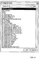
- the processing of displaying the symbol names, which have been written to the map file 144b, as a list as depicted in FIG. 6 may be executed in the control unit 110, and the tester may be caused to select the symbol name of the data which are wished to be read or updated.
- the tester since the meaning of data corresponding to a symbol name is most often reflected in the symbol name, the tester can intuitively select, without referring to a manual or the like, the symbol name of the data which are wished to be read or updated. Since the data which are wished to be read or updated can be specified by the symbol name, without referring each time to a manual, the present embodiment makes it possible to improve the efficiency of maintenance and inspection operation by comparison with the conventional technique which uses a function code for specification.
- the tester can specify intuitively the data which are wished to be read or updated, from among the data stored in the memory of the drive device 20, by using a symbol name. Further, in the present embodiment, since the conversion from a symbol name to an address is executed in the test device 10, no extra processing load is applied to the drive device 20. In addition, even when the data which are the object of reading or updating are appended, modified, or deleted, it is possible to adapt flexibly to those operations by updating the map file 144b stored in the test device 10.
- the map file 144b obtained by executing the map file conversion processing with the map file conversion device 40 with respect to the map file generated in the process of building the control program stored in the drive device 20 is stored in the test device 10. This is because where the version of the control program stored in the drive device 20 and the version of the map file stored in the test device 10 differ from each other (for example, when the version of the source code and header file used when the control program is built and the version of the source code and header file used to generate the map file differ from each other), the correct address is not always obtained by the symbol name/address conversion processing.
- source codes and header files of a plurality of versions are created in response to requests from the user of the drive device 20 (for example, manufacturers of electric automobiles), and a discrepancy often occurs between the version of the control program stored in the drive device 20 and the version of the map file stored in the test device 10. Accordingly, in order to avoid the occurrence of such a discrepancy, it is possible to store version information indicating the version of the control program in the drive device 20, and acquire the version information stored in the drive device 20 and use the map file corresponding to the version indicated by the version information in the test device 10.
- a plurality of map files each of which has a different version are stored in the test device 10, and the processing of selecting and using the map file corresponding to the version indicated by the version information acquired from the drive device 20, from among the plurality of map files, is executed in the control unit 110 of the test device 10.
- the storage destination of the plurality of map files each of which has a different version is not limited to the nonvolatile storage unit 144 of the test device 10 and may be a server device (or a network-adapted hard disk) that can be accessed by the test device 10 through an electric communication circuit such as Internet.
- a map file obtained by subjecting a map file generated in the process of building the control program to the map file conversion processing by the map file conversion device 40 may be stored as the version information in the drive device 20, the version information (map file) may be acquired from the drive device 20 before the test is started (for example, when the connection of the drive device 20 through a signal line is detected) by the test device 10, and this map file may be used therein.
- the present invention may be also applied to a test device for performing tests at the development stage of the drive device 20.
- the present invention may be also applied to a controller that communicates with the drive device 20 and performs the operation control thereof when the drive device 20 is actually used.
- the present invention may be applied to an onboard controller (VCU) that preforms operation control of the drive device 20 in response to the operation performed by the driver of the electric automobile.
- VCU onboard controller
- the application objects of the present invention are not limited to controllers that control drive devices for electric automobiles.
- the present invention may be also applied to a controller for controlling, for example, a drive device that drives a motor that lifts an elevator or a drive device that drives the motor of an air conditioner.
- the source code of the control program of the drive device 20 is described using the C language, but it goes without saying that the source code may be described using another programming language, such as C++.
- any programming language may be used that can assign a symbol name reflecting the meaning of data to be stored in the memory of the drive device 20 in the process of executing the control program and can describe the source code using this symbol name.
- the test program 144a that causes the control unit 110 to execute the symbol name/address conversion processing which notably represents the feature of the present invention (in order words, the program that causes the control unit 110 to function as a conversion means for executing the symbol name/address conversion processing) is stored in advance in the nonvolatile storage unit of the test device 10.
- this program may be also written and distributed on a computer-readable recording medium such as a CD-ROM (Compact Disk-Read Only Memory), or may be distributed by downloading through an electric communication circuit such as Internet.
Landscapes
- Engineering & Computer Science (AREA)
- Software Systems (AREA)
- Theoretical Computer Science (AREA)
- General Engineering & Computer Science (AREA)
- General Physics & Mathematics (AREA)
- Physics & Mathematics (AREA)
- Power Engineering (AREA)
- Transportation (AREA)
- Mechanical Engineering (AREA)
- Life Sciences & Earth Sciences (AREA)
- Sustainable Energy (AREA)
- Sustainable Development (AREA)
- Data Mining & Analysis (AREA)
- Databases & Information Systems (AREA)
- Tests Of Electronic Circuits (AREA)
- Control Of Electric Motors In General (AREA)
- Stored Programmes (AREA)
Abstract
Description
- The invention relates to a control technique for a drive device that performs drive control of a motor by controlling the power supplied to the motor.
- As the interest in environmental issues has been growing in recent years, battery-powered electric automobiles using an onboard battery as a power source (referred to hereinbelow simply as "electric automobiles") have attracted attention. In an electric automobile, a motor such as a three-phase AC motor is installed as a power source. Also installed are a drive device, such as an inverter, that converts the DC power supplied from the onboard battery into AC power and supplies the converted power to the motor, and a controller (VCU (vehicle control unit)) that controls the drive device. The controller adjusts various command values, such as a torque command, which are provided to the drive device, according to a driver's operation, and the drive device adjusts the power, which is supplied to the motor, according to the command value provided from the controller. As a result, the torque or revolution speed of the motor changes and travel control corresponding to the driving operation is realized. Further, the controller acquires, through a signal line, various data (for example, parameter information such as motor constants, or data representing a current value of each phase) that have been stored in the memory of the drive device and also executes the processing of controlling the display of various meters on the basis of those data. As a result, the drive can determine a vehicle state.
- Patent Literature 1:
Japanese Patent Application Publication No. S61-279906 - Patent Literature 2:
Japanese Patent Application Publication No. 2009-245456 - Patent Literature 3:
Japanese Patent Application Publication No. 2005-352612 - Patent Literature 4:
Japanese Patent Application Publication No. 2003-150207 - Thus, various data are exchanged between the drive device and the controller via the signal line. Further, when the drive device is maintained and inspected, a test device such as a personal computer is connected through the controller to the drive device and various tests, such as the observation of motor behavior when the data stored in the memory of the drive device are referred to or updated, are performed. The access by an external device such as a test device to the data stored in the memory of the drive device has been conventionally realized by assigning a unique function code to each data and specifying the data which are desired to be read from or written into the memory by using the function code. More specifically, a table in which the function codes of the data have been written in association with the header address (referred to hereinbelow simply as "address") of a storage area where the data are to be stored in the memory is stored in the drive device. Then, the drive device is caused to execute the processing of converting the function code provided from the test device as a code specifying the data which are the object of reading or updating into an address with reference to the contents stored in the table, and reading and returning the data stored in the storage area indicated by the address or updating the data.
- However, the following problems are associated with the specification of data by the function codes. Firstly, the operation efficiency during maintenance and inspection is poor. Since a function code is mostly assigned as a sequential number, it is difficult to determine which data are represented from the function code, and it is also difficult to cause the tester to analogize the function codes of data which are wished to be read or updated. For this reason, the tester needs to perform various tests while examining, by referring each time to, for example, a manual, which function code has been allocated to the data which are wished to be read or updated. Secondly, each time the data which are the object of reading or updating are appended, modified, and deleted, the table stored in each drive device needs to be updated. Thirdly, an extra processing load is placed on the drive device which is the object of maintenance and inspection due the conversion of the function code to the address, and it is possible that accurate inspection would not be performed.
- The present invention has been created to resolve the above-described problems, and it is an objective of the present invention to provide a technique which is capable of flexibly adapting to addition, modification and deletion of data which are the object of reading or updating and enables intuitive specification of data which are wished to be read or updated, without applying an extra processing load to a drive device.
- In accordance with the present invention, in order to resolve the above-mentioned problems, a map file is stored and the below-described conversion means is provided in a controller that controls a drive device that performs drive control of a motor according to a control program loaded in a memory. In the map file, the address of a storage area where the data are to be stored is written in association with a symbol name (a string representing a variable name) included in a source code of the control program as an identifier for identifying data that are stored in the memory of the drive device when the control program is loaded and executed. The conversion means executes the processing of converting a symbol name provided to indicate the data which are an object of reading or updating to an address with reference to the map file. The controller in accordance with the present invention specifies the data which are the object of reading or object of updating by the address obtained by the conversion means and instructs the drive device to read or update the data.
- Specific examples of the controller include a test device that is used when the drive device is maintained or inspected and an onboard controller (the aforementioned VCU). For example, where the present invention is applied to a test device, the tester can specify the data which are wished to be read or updated by using a symbol name. A string such that the meaning of data can be intuitively recognized is most often used as a symbol name corresponding to each data in a source code for a control program. Therefore, in accordance with the present invention, the data which are desired to be read or updated can be specified by the tester by using a symbol name that can be easily intuitively recognized, and the efficiency of maintenance and inspection operations can be increased over the conventional one. Further, in accordance with the present invention, the conversion from the symbol name to the address is executed at the controller side. Therefore, no extra load is applied to the drive device. In addition, by updating the map file on the controller side, it is possible to adapt flexibly to the addition, modification, and deletion of data that are the object of reading or updating.
-
Patent Literatures 1 to 4 disclose the technique by which a symbol name in the source code of a program is associated with the address of storage destination of data identified by the symbol name, and the access based on the symbol name is enabled. However, the inventions disclosed in Patent Literatures 1-4 do not relate to a technique for controlling the drive device of a motor and are different from the invention of the present application. - The C language is an example of a programming language for describing the source code of the abovementioned control program. A specific feature of the C language is that this language can describe a program executing the processing same as that of the assembler or machine language, for example, can realize flexible memory access based on address specification, but the coding is easier than in the assembler or machine language. For this reason, the C language is widely used for coding of programs for control systems. Where the source code of a control program is described using the C language, in addition to the previously prepared data types such as a char type or a short type, it is possible to define a structure type which is a new data type combining those existing data types, and the variable of this structure type (this variable can be also referred to simply as "structure") can be used. Where the variable of a structure type is used in the source code of a control program, it is preferred that a map file be used in which the address of a storage area for storing data corresponding to constituent elements (referred to hereinbelow as "members") of this structure be written in association with symbol names representing each of the members. Where such a map file is stored in a controller, the data which are the objects of reading or updating can be specified in member units of the structure.
- The map file is generated together with an executable file in the process of generating the executable file on the basis of a source code and a header file. However, in such a typical map file, only the address of a storage area for storing data on the structure is written in association with the symbol name of the variable of the structure type, and information relating to the members is not included. Therefore, where the typical map file is used, the data which are the object of reading or updating cannot be specified in the member units of the structure. Accordingly, a map file conversion device may be provided for subjecting the typical map file to map file conversion processing of appending the address of the storage area for the data corresponding to a structure member in association with the symbol name of the member, and the map file subjected to such map file conversion processing may be stored in the controller.
- A specific configuration of the map file conversion device may include input means for inputting various data and control means for executing the map file conversion processing. Thus, the source code of the control program of the drive device that performs drive control of a motor, a definition file that defines a data type that has been used in the source code (a header file when the source code is described in the C language), and a map file generated together with the control program on the basis of the source code and definition file are inputted through the input means to the map file conversion device. Where the variable of a structure type is included in the source code received through the input means, the control means executes map file conversion processing of specifying members of the structure with reference to the definition file which has been received through the same input means, and appending an address obtained by adding an offset corresponding to the data type of each preceding member to the address of the storage area in which the structure is stored in the drive device, in association with the symbol name of each member, to the map file received through the same input means.
- In another preferred embodiment, version information indicating the version of a control program is stored in advance in the drive device, and the conversion means of the controller acquires the verification information from the drive device and uses a map file corresponding to the version indicated by the version information. For example, an embodiment can be considered in which a plurality of map files with different versions are stored in the controller, and the map file of the versions indicated by the version information acquired from the drive device, which is the control object, is used in the conversion means. Further, a map file itself may be used as the version information. More specifically, a map file of versions corresponding to a control program may be stored in advance together with the control program in the drive device, and the map file may be acquired from the drive device and used in the controller. Where the versions of the control program and map file do not match, the correct address sometimes cannot be obtained by the conversion means, but the occurrence of such an incompatibility can be avoided in the present embodiment.
-
-
FIG. 1 illustrates a configuration example of atest system 1 including atest device 10 of one embodiment of the controller in accordance with the present invention. -
FIG. 2 illustrates a configuration example of thetest device 10. -
FIG. 3 illustrates a configuration example of a mapfile conversion device 40 used for generating amap file 144b stored in thetest device 10. -
FIG. 4 illustrates a step for generating themap file 144b. -
FIG. 5 is a flowchart illustrating the flow of map file generation processing executed by the mapfile conversion device 40. -
FIG. 6 illustrates an example of a symbol name list displayed on a display unit of a user I/F unit 120 of thetest device 10. - An embodiment of the present invention will be described hereinbelow with reference to the drawings.
-
FIG. 1 illustrates a configuration example of atest system 1 including atest device 10 of one embodiment of the controller in accordance with the present invention. Thetest system 1 serves for maintaining and inspecting adrive device 20 which is installed together with amotor 30 on an electric automobile. As depicted inFIG. 1 , thetest system 1 includes thedrive device 20 which is the object of maintenance and inspection, themotor 30 which is drive-controlled by thedrive device 20, and thetest device 10 which plays the role of a controller that controls thedrive device 20 while the maintenance and inspection are executed. - The
motor 30 is a three-phase AC motor. Thedrive device 20 is an inverter that converts DC power supply, for example from an onboard battery, into three-phase AC power and supplies the converted power to themotor 30. Thedrive device 20 includes a control unit (not shown in the figure) which executes, according to a preinstalled control program, the processing of controlling the current value of each phase of a three-phase AC voltage supplied to themotor 30 in response to various commands provided from the controller (VCU in the actual operation; thetest device 10 in the present embodiment), and a memory that is used as a work area when the control program is executed. - The control program stored in the
drive device 20 is an executable file obtained by performing compiling and linking with respect to a source code that describes in a predetermined programming language the steps in the processing realized according to the control program. In the present embodiment, the C language is used as the programming language for describing the source code. This is because a specific feature of the C language is that this language can describe a program executing the processing same as that of the assembler or machine language, for example, can realize flexible memory access based on address specification, but the coding is easier than in the assembler or machine language, and this language can be advantageously used for coding the programs for control systems. - The
test device 10 is, for example, a personal computer and connected to thedrive device 20 by a signal line such as a twist-pair cable. In the present embodiment, changes in the operation of themotor 30 are observed by providing various commands from thetest device 10 to thedrive device 20 through the signal line, or the maintenance and inspection of thedrive device 20 are advanced by reading out the data stored in the memory of thedrive device 20 and confirming the values thereof. - As mentioned hereinabove, in the conventional technique, the access from an external device to data stored in the memory of the
drive device 20 is typically realized by assigning a unique function code to each data and specifying the data which are the object of reading or updating by using the function codes. The difference between the present embodiment and the conventional technique is that in the present embodiment, the tester can specify the data which are the object of reading or updating by using the symbol name of an external variable included in the source code of the control program as an identifier for identifying the data stored in the memory of thedrive device 20. The reason why the data, which are the object of reading or updating, are specified by the symbol name is that a symbol name, which allows the meaning of data to be intuitively recognized, is often used in a source code and that the data which are desired to be read or updated can be intuitively specified by the tester without referring each time to, for example, a manual. -
FIG. 2 illustrates a configuration example of thetest device 10. As depicted inFIG. 2 , thetest device 10 has acontrol unit 110, a user interface (abbreviated hereinbelow as "I/F")unit 120, a communication I/F unit 130, astorage unit 140, and abus 150 for exchanging data between those constituent elements. - The
control unit 110 is, for example, a CPU (Central Processing Unit). Thecontrol unit 110 functions as a control center of thetest device 10 by executing thetest program 144a stored in the storage unit 140 (more accurately, the nonvolatile storage unit 144). - The user I/
F unit 120 includes a display unit and an operation unit (none is depicted inFIG. 2 ). The display unit is constituted by a liquid crystal display and a drive circuit thereof. Various screens for performing the maintenance and inspection of thedrive device 20 are displayed, under the control performed by thecontrol unit 110, on the display unit. The operation unit is constituted by a pointing device such as a mouse, or a keyboard. The operation unit allows the tester to perform various input operations for performing the maintenance and inspection of thedrive device 20 and provides data corresponding to the contents of the operation performed by the pointing device to thecontrol unit 110. As a result, the contents of operations performed by the tester is transmitted to thecontrol unit 110. - The communication I/
F unit 130 is, for example, a NIC (Network Interface Card) and connected to thedrive device 20 by a signal line such as a twist-pair cable. The communication I/F unit 130 provides the data received from thedrive device 20 through the signal line to thecontrol unit 110, and transmits the data provided from thecontrol unit 110 to thedrive device 20 through the signal line. - The
storage unit 140 includes avolatile storage unit 142 and anonvolatile storage unit 144. Thevolatile storage unit 142 is constituted, for example, by a RAM (Random Access Memory). Thevolatile storage unit 142 is used by thecontrol unit 110 as a work area when thetest program 144a is executed. Thenonvolatile storage unit 144 is constituted, for example, by a hard disk or a flash memory. Thetest program 144a and themap file 144b are stored in advance in thenonvolatile storage unit 144. OS software that configures an OS (Operating System) is also stored, in addition to thetest program 144a and themap file 144b, in thenonvolatile storage unit 144. Due to a weak connection with the present invention, this software is not depicted in the figure. - Where the power supply (not depicted in the figure) of the
test device 10 is switched on, thecontrol unit 110 reads the OS software from thenonvolatile storage unit 144 into thevolatile storage unit 142 and starts the execution thereof. Where thecontrol unit 110 is instructed through the operation unit of the user I/F unit 120 in this state to execute thetest program 144a, the control unit reads thetest program 144a from thenonvolatile storage unit 144 into thevolatile storage unit 142 and starts the execution thereof. Thecontrol unit 110 actuated according to thetest program 144a displays various screens that support the execution of maintenance and inspection of thedrive device 20 on the display unit of the user I/F unit 120. Where a symbol name that indicates data which are the object of reading or updating is inputted by the operation of the operation unit of the user I/F unit 120, thecontrol unit 110 communicates with thedrive device 20 in order to read or update the data specified by the symbol name. - More specifically, initially, the
control unit 110 executes the conversion processing of converting, by using themap file 144b, the symbol name inputted to indicate the data which are the object of reading or updating to the address of the storage area in the memory of thedrive device 20 for the data indicated by the symbol name, notifies through the signal line thedrive device 20 of the address obtained by the conversion processing, and specifies the data which are the object of reading or updating. Thedrive device 20 executes the processing of reading and returning the data stored in the storage area indicated by the address provided in such a manner, or the processing of updating the data stored in this storage area. As a result, the data specified by the tester are read or updated. - In the
map file 144b, the address of the storage area for storing the data corresponding to the symbol name in thedrive device 20 in which the control program is loaded into the memory and executed is written in association with the symbol name of the external variable included in the source code of the control program. In this case, the symbol name and the address are written in themap file 144b in association with each other only with respect to the external variable from among the variables included in the source code, because with respect to the variables other than the external variable, the storage area is dynamically secured in the process of executing the control program and the address to be associated with the symbol name is not fixed. - A map file in which the symbol name of the external variable included in the source code is associated with the address of a storage area for storing the data corresponding to the symbol name is generated together with an executable file when the executable file is built by compiling and linking from the source code and header file. However, the
map file 144b stored in thenonvolatile storage unit 144 thetest device 10 is obtained by subjecting the typical map file to the map file conversion processing with the mapfile conversion device 40 depicted inFIG. 3 , and is not the typical map file generated together with a control program when the control program is built. This is the second feature of the present embodiment. -
FIG. 3 is a block diagram illustrating a configuration example of the mapfile conversion device 40. Similarly to thetest device 10, the mapfile conversion device 40 is a personal computer and the hardware configuration thereof is the same as that of thetest device 10. Thus, as depicted inFIG. 4 , the mapfile conversion device 40 has acontrol unit 410, a user I/F unit 420, a communication I/F unit 430, astorage unit 440, and abus 450 for exchanging data between those constituent elements. Thestorage unit 440 has avolatile storage unit 442 and anonvolatile storage unit 444. A mapfile conversion program 444a for realizing the map file conversion processing, which notably represents the feature of the present embodiment, in thecontrol unit 410 is stored in advance in thenonvolatile storage unit 444. -
FIG. 4 illustrates the map file conversion processing executed by thecontrol unit 410 according to the mapfile conversion program 444a. More specifically,FIG. 4(a) illustrates the summary of the map file conversion processing. As depicted inFIG. 4(a) , in the present embodiment, an executable file is generated by building (compiling and linking) from a source code SC (concerning a specific example, seeFIG. 4(b) ) and a header file HF (concerning a specific example, seeFIG. 4(b) ) of the control program. The executable file is installed as a control program in thedrive device 20. In the abovementioned building process, a typical map file BMF (seeFIG. 4(b) ) is generated together with the control program (executable file). The address of the storage area of data corresponding to an external variable included in the source code at the time the executable file is loaded into the memory is written into the map file BMF in association with the symbol name of the external variable. - As depicted in
FIG. 4(a) , in the map file conversion processing of the present embodiment, the source code SC and header file HF of the control program and the map file BMF generated in the process of building the control program are the input data. For example, where a computer device executing the building process is connected by a signal line to the communication I/F unit 430 of the mapfile conversion device 40, the input data are inputted from the computer device executing the building process to the mapfile conversion device 40 through the communication I/F unit 430. In other words, the communication I/F unit 430 depicted inFIG. 3 plays the role of an input means for inputting the input data to the mapfile conversion device 40. In the present embodiment, a map file AMF is generated by executing the map file conversion processing on the basis of those input data, and the map file AMF is stored as theaforementioned map file 144b in thenonvolatile storage unit 144 of thetest device 10. -
FIG. 5 is a flowchart illustrating the flow of map file conversion processing. As depicted inFIG. 5 , in the map file conversion processing, thecontrol unit 410 initially extracts the variable of a structure type from among the external variables included in the source code inputted through the communication I/F unit 430 (step SA100). For example, when the source code SC and header file HF depicted inFIG. 4(b) are inputted, an external variable gAD0_Value of an ADC_AD0_VALUE type (this data type is defined in the header file HF) is included as the external variable of a structure type in the source code SC. Therefore, the external variable g AD0_Value is extracted in the step SA100. Further, since the external variable g AD0_Value of the ADC_AD0_VALUE type is an external variable, in the map file BMF inFIG. 4(b) , the address fff80092 of the storage area for storing the data corresponding to the variable is written in association with the variable name g AD0_Value of the variable. - Then, the
control unit 410 specifies the symbol name and data type of each member of the structure extracted in step SA100 by referring to the header file HF included in the inputted data (step SA110). For example, in the header file HF depicted inFIG. 4(b) , the structure of the ADC_AD0_VALUE type is defined as being constituted by eight members (mIu, mIv, mIw, mAi1, mAi2, mMAi1, mMAi2, and mVDC) of the respective short type, and a name reflecting the meaning of the data which are to be stored in each of the members is assigned to each of those members. For example, data representing the electric current of a u phase which is supplied from thedrive device 20 to themotor 30 is stored in the member mIu, data representing the electric current of a v phase which is supplied from thedrive device 20 to themotor 30 is stored in the member mIv, and data representing the electric current of a w phase which is supplied from thedrive device 20 to themotor 30 is stored in the member mIw. In the step SA110, (gAD0_Value.mIu, short), (gAD0_Value.mIv, short), (gAD0_Value.mIw, short), (gAD0_Value.mAi1, short), (gAD0_Value.mAi2, short), (gAD0_Value.mMAi1, short), (gAD0_Value.mMAi2, short), and (gAD0_Value.mVDC, short) are extracted as the symbol name and data type of the members of the external variable gAD0_Value. - Further, the
control unit 410 appends the address obtained by adding an offset corresponding to the data type of each member preceding the member represented by the symbol name, in association with the symbol name of each member specified in step SA110, to the map file BMF inputted through the communication I/F unit 430 and generates the map file AMF (step SA120). For example, since the member mIu is the first member (that is, there is no preceding member), the offset is 0 and thecontrol unit 410 appends the address (fff80092 + 0 = fff80092) in association with the symbol name (gAD0_Value.mIu) representing this member to the map file BMF. Concerning the member mIv, which is the second member, since the data type of the preceding member (that is, the member mIu) is a short type (2-byte data type), the offset is 2. Therefore, thecontrol unit 410 appends the address (fff80092 + 2 = fff80094) in association with the symbol name (gAD0_Value.mIv) representing the member mIv to the map file BMF. Concerning the member mIw, which is the third member, since the data types of the preceding members (the members mIu and mIv) are each a short type (2-byte data type), the offset is 4. Therefore, thecontrol unit 410 appends the address (fff80092 + 4 = fff80096) in association with the symbol name (gAD0_Value.mIw) representing the member mIw to the map file BMF. Similar processing is performed with respect to the fourth and subsequent members. As a result, the map file AMF depicted inFIG. 4(b) is obtained. Where a char-type variable is included in the members of the structure, the offset may be calculated by performing the so-called boundary adjustment. - Described hereinabove is the flow of map file conversion processing in the map
file conversion device 40. Where no external variable of a structure type is included in the source code inputted to the mapfile conversion device 40, the map file inputted to the mapfile conversion device 40 is outputted, as is, as the converted map file. - It is noteworthy that in the present embodiment, the map file (map file AMF depicted in
FIG. 4(b) ) subjected to the map file conversion processing with the mapfile conversion device 40, rather than the typical file (for example, the map file BMF depicted inFIG. 4(b) ) generated together with the control program, is stored in thenonvolatile storage unit 144 of thetest device 10. The reason therefor is explained below. - In the typical map file, although the header address of the storage area for storing a structure is written in association with the symbol name of the variable of the structure type, no information relating to the members of the structure is included. Therefore, even though the typical map file is stored in the
test device 10, the data which are the object of reading or updating cannot be specified by the symbol name in the member units of the structure. By contrast, in the present embodiment, the map file AMF obtained by the map file conversion processing is stored as themap file 144b in thetest device 10. Therefore, the data which are the object of reading or updating can be specified by the tester by the symbol names in the member units of the structure. To enable such specification of the data which are the object of reading or updating in the member units of the structure, in the present embodiment, the map file subjected to the map file conversion processing with the mapfile conversion device 40 is stored in thetest device 10. It goes without saying that when it is not necessary to specify the data which are the object of reading or updating in the member units of the structure, the typical map file may be stored as themap file 144b in thetest device 10. - Thus, in the present embodiment, the map file subjected to the map file conversion processing performed by the map
file conversion device 40 is stored in thenonvolatile storage unit 144 of thetest device 10. For example, when the map file AMF depicted inFIG. 4(b) is stored as themap file 144b in thenonvolatile storage unit 144 of thetest device 10, the tester can refer to or update the current value of the u phase, which is supplied from thedrive device 20 to themotor 30, by specifying the symbol name (gAD0_Value.mIu). - Further, the processing of displaying the symbol names, which have been written to the
map file 144b, as a list as depicted inFIG. 6 may be executed in thecontrol unit 110, and the tester may be caused to select the symbol name of the data which are wished to be read or updated. As mentioned hereinabove, since the meaning of data corresponding to a symbol name is most often reflected in the symbol name, the tester can intuitively select, without referring to a manual or the like, the symbol name of the data which are wished to be read or updated. Since the data which are wished to be read or updated can be specified by the symbol name, without referring each time to a manual, the present embodiment makes it possible to improve the efficiency of maintenance and inspection operation by comparison with the conventional technique which uses a function code for specification. - As described hereinabove, in the
test system 1 of the present embodiment, the tester can specify intuitively the data which are wished to be read or updated, from among the data stored in the memory of thedrive device 20, by using a symbol name. Further, in the present embodiment, since the conversion from a symbol name to an address is executed in thetest device 10, no extra processing load is applied to thedrive device 20. In addition, even when the data which are the object of reading or updating are appended, modified, or deleted, it is possible to adapt flexibly to those operations by updating themap file 144b stored in thetest device 10. - One embodiment of the present invention is explained hereinabove, but it goes without saying that this embodiment may be changed in the following manner.
- (1) In the embodiment, the
map file 144b obtained by executing the map file conversion processing with the mapfile conversion device 40 with respect to the map file generated in the process of building the control program stored in thedrive device 20 is stored in thetest device 10. This is because where the version of the control program stored in thedrive device 20 and the version of the map file stored in thetest device 10 differ from each other (for example, when the version of the source code and header file used when the control program is built and the version of the source code and header file used to generate the map file differ from each other), the correct address is not always obtained by the symbol name/address conversion processing. - However, in most cases, source codes and header files of a plurality of versions are created in response to requests from the user of the drive device 20 (for example, manufacturers of electric automobiles), and a discrepancy often occurs between the version of the control program stored in the
drive device 20 and the version of the map file stored in thetest device 10. Accordingly, in order to avoid the occurrence of such a discrepancy, it is possible to store version information indicating the version of the control program in thedrive device 20, and acquire the version information stored in thedrive device 20 and use the map file corresponding to the version indicated by the version information in thetest device 10. - For example, a plurality of map files each of which has a different version (map files which have each been subjected to the map file conversion processing by the map file conversion device 40) are stored in the
test device 10, and the processing of selecting and using the map file corresponding to the version indicated by the version information acquired from thedrive device 20, from among the plurality of map files, is executed in thecontrol unit 110 of thetest device 10. The storage destination of the plurality of map files each of which has a different version is not limited to thenonvolatile storage unit 144 of thetest device 10 and may be a server device (or a network-adapted hard disk) that can be accessed by thetest device 10 through an electric communication circuit such as Internet. Further, a map file obtained by subjecting a map file generated in the process of building the control program to the map file conversion processing by the mapfile conversion device 40 may be stored as the version information in thedrive device 20, the version information (map file) may be acquired from thedrive device 20 before the test is started (for example, when the connection of thedrive device 20 through a signal line is detected) by thetest device 10, and this map file may be used therein. - (2) In the embodiment, an example is explained in which the present invention is applied to a test device for performing the maintenance and inspection of the
drive device 20, but it goes without saying that the present invention may be also applied to a test device for performing tests at the development stage of thedrive device 20. Further, the present invention may be also applied to a controller that communicates with thedrive device 20 and performs the operation control thereof when thedrive device 20 is actually used. For example, when themotor 30 and thedrive device 20 are installed on an electric automobile, the present invention may be applied to an onboard controller (VCU) that preforms operation control of thedrive device 20 in response to the operation performed by the driver of the electric automobile. Further, the application objects of the present invention are not limited to controllers that control drive devices for electric automobiles. The present invention may be also applied to a controller for controlling, for example, a drive device that drives a motor that lifts an elevator or a drive device that drives the motor of an air conditioner. - (3) In the embodiment, the case is explained in which the source code of the control program of the
drive device 20 is described using the C language, but it goes without saying that the source code may be described using another programming language, such as C++. Essentially, any programming language may be used that can assign a symbol name reflecting the meaning of data to be stored in the memory of thedrive device 20 in the process of executing the control program and can describe the source code using this symbol name. - (4) In the embodiment, the
test program 144a that causes thecontrol unit 110 to execute the symbol name/address conversion processing which notably represents the feature of the present invention (in order words, the program that causes thecontrol unit 110 to function as a conversion means for executing the symbol name/address conversion processing) is stored in advance in the nonvolatile storage unit of thetest device 10. However, this program may be also written and distributed on a computer-readable recording medium such as a CD-ROM (Compact Disk-Read Only Memory), or may be distributed by downloading through an electric communication circuit such as Internet. This is because by causing the control unit of a typical computer device such as a personal computer to operate according to the program distributed in such a manner, it is possible to cause the computer device to function as thetest device 10 of the embodiment. The same is true with respect to the mapfile conversion program 444a. -
- 1 test system
- 10 test device
- 110, 410 control units
- 120, 420 user I/F units
- 130, 430 communication I/F units
- 140, 440 storage units
- 142, 442 volatile storage units
- 144, 444 nonvolatile storage units
- 144a test program
- 144b map file
- 444a map file conversion program
- 150, 450 buses
- 20 drive device
- 30 motor
- 40 map file conversion device
Claims (5)
- A controller that controls a drive device that executes drive control of a motor according to a control program loaded in a memory,
the controller comprising:a map file in which a symbol name included in a source code of the control program as an identifier for identifying data stored in the memory is associated with an address of a storage area storing the data; andconversion means for converting a symbol name provided to indicate data, which are an object of reading or an object of updating, into an address with reference to the map file, whereinthe controller instructs the drive device to read or update data stored in the storage area indicated by the address obtained by the conversion means. - The controller according to claim 1, wherein
in the map file an address of a storage area that stores data corresponding to a member is written in association with a symbol name of each member with respect to a variable of a structure type. - The controller according to claim 1, wherein
version information indicating a version of a control program is stored in the drive device; and
the conversion means uses a map file corresponding to the version indicated by the version information stored in the drive device. - The controller according to claim 2, wherein version information indicating a version of a control program is stored in the drive device; and
the conversion means uses a map file corresponding to the version indicated by the version information stored in the drive device. - A map file conversion device comprising:input means; andcontrol means, whereinthe control meansreceives through the input means a source code of a control program of a drive device that performs drive control of a motor, a definition file that defines a data type that has been used in the source code, and a map file generated together with the control program on the basis of the source code and the definition file, andwhen a variable of a structure type is included in the source code received through the input means, the control means executes map file conversion processing of specifying members of the variable of the structure type with reference to the definition file which has been received through the input means, and appending to the map file received through the input means an address obtained by adding an offset corresponding to a data type of each preceding member to an address of a storage area in which the variable of the structure type is stored in the drive device, in association with a symbol name of each member.
Applications Claiming Priority (2)
| Application Number | Priority Date | Filing Date | Title |
|---|---|---|---|
| JP2013095383 | 2013-04-30 | ||
| PCT/JP2014/059723 WO2014178255A1 (en) | 2013-04-30 | 2014-04-02 | Controller and map file conversion device |
Publications (2)
| Publication Number | Publication Date |
|---|---|
| EP2993780A1 true EP2993780A1 (en) | 2016-03-09 |
| EP2993780A4 EP2993780A4 (en) | 2017-01-11 |
Family
ID=51843390
Family Applications (1)
| Application Number | Title | Priority Date | Filing Date |
|---|---|---|---|
| EP14791349.5A Withdrawn EP2993780A4 (en) | 2013-04-30 | 2014-04-02 | Controller and map file conversion device |
Country Status (5)
| Country | Link |
|---|---|
| US (1) | US9751410B2 (en) |
| EP (1) | EP2993780A4 (en) |
| JP (1) | JP6028856B2 (en) |
| CN (1) | CN105027425B (en) |
| WO (1) | WO2014178255A1 (en) |
Families Citing this family (11)
| Publication number | Priority date | Publication date | Assignee | Title |
|---|---|---|---|---|
| JP2017016503A (en) * | 2015-07-03 | 2017-01-19 | 富士通株式会社 | Compiler, compiling device, and compiling method |
| TWI571811B (en) * | 2015-11-05 | 2017-02-21 | 財團法人資訊工業策進會 | Variable definition modification device and method for process model integration systems |
| KR20170115696A (en) * | 2016-04-08 | 2017-10-18 | 엘에스산전 주식회사 | Inverter system |
| JP2018055654A (en) * | 2016-09-30 | 2018-04-05 | オムロン株式会社 | Information processing device, and information processing method and program |
| CN109032500B (en) * | 2018-06-11 | 2021-12-14 | 广州视源电子科技股份有限公司 | Data storage method and device of single-chip microcomputer, single-chip computer, and storage medium |
| JP6823027B2 (en) * | 2018-09-18 | 2021-01-27 | ファナック株式会社 | Numerical control device |
| JP7211135B2 (en) * | 2019-02-12 | 2023-01-24 | 富士電機株式会社 | Information processing device, information processing method, and information processing system |
| JP7067520B2 (en) * | 2019-03-28 | 2022-05-16 | オムロン株式会社 | Development support equipment, control methods for development support equipment, information processing programs, and recording media |
| WO2020213059A1 (en) * | 2019-04-16 | 2020-10-22 | 三菱電機株式会社 | Program creation assistance device, program creation assistance method, and program |
| JP7391603B2 (en) * | 2019-10-16 | 2023-12-05 | ファナック株式会社 | Control device with setting data changing function and method for changing setting data of the control device |
| CN115544939A (en) * | 2022-10-28 | 2022-12-30 | 中科亿海微电子科技(苏州)有限公司 | Processing method and device for FPGA configuration file and computer readable storage medium |
Family Cites Families (23)
| Publication number | Priority date | Publication date | Assignee | Title |
|---|---|---|---|---|
| JPS61279906A (en) | 1985-06-05 | 1986-12-10 | Matsushita Electric Ind Co Ltd | Programmable controller |
| JPH0546377A (en) * | 1991-08-08 | 1993-02-26 | Hitachi Ltd | Control program creation method and creation apparatus thereof |
| JPH11338731A (en) * | 1998-05-21 | 1999-12-10 | Oki Electric Ind Co Ltd | Data processor |
| DE19836748C1 (en) * | 1998-08-13 | 2000-04-20 | Siemens Ag | Method for applying control data of an electronic motor vehicle control unit |
| US6718533B1 (en) * | 1999-02-26 | 2004-04-06 | Real-Time Innovations, Inc. | Method for building a real-time control system with mode and logical rate |
| JP2002223586A (en) * | 2001-01-26 | 2002-08-09 | Keyence Corp | Method and apparatus for analyzing operating state of electric motor driver |
| US6854109B2 (en) * | 2001-06-07 | 2005-02-08 | International Business Machines Corporation | Tool for converting .MAP file formats |
| JP5088842B2 (en) * | 2001-08-08 | 2012-12-05 | 株式会社キーエンス | Detailed display method when abnormality occurs in motor drive device and motor drive device |
| JP2003061388A (en) * | 2001-08-10 | 2003-02-28 | Keyence Corp | Method for setting parameters of motor drive and motor drive |
| JP2003070286A (en) * | 2001-08-22 | 2003-03-07 | Keyence Corp | Motor driver having character information display |
| JP2003150207A (en) | 2001-11-12 | 2003-05-23 | Toshiba Corp | Plant control system |
| JP4444677B2 (en) * | 2004-01-20 | 2010-03-31 | クラリオン株式会社 | Search data update method and update system |
| JP4226491B2 (en) * | 2004-02-26 | 2009-02-18 | 株式会社ザナヴィ・インフォマティクス | Search data update system and navigation device |
| JP4420210B2 (en) | 2004-06-08 | 2010-02-24 | オムロン株式会社 | Program development support apparatus and processing method |
| JP5002140B2 (en) * | 2005-08-24 | 2012-08-15 | クラリオン株式会社 | Navigation device and navigation processing method |
| US7853388B2 (en) * | 2006-02-23 | 2010-12-14 | Siemens Industry, Inc. | Devices, systems, and methods for controlling a braking system |
| US20080229165A1 (en) * | 2007-03-16 | 2008-09-18 | Etas, Inc. | Address translation system for use in a simulation environment |
| US8131765B2 (en) * | 2008-10-14 | 2012-03-06 | Lenovo (Singapore) Pte. Ltd. | Apparatus, system and method for caching writes by multiple clients to a virtualized common disk image |
| US8397222B2 (en) * | 2008-12-05 | 2013-03-12 | Peter D. Warren | Any-to-any system for doing computing |
| US8396870B2 (en) * | 2009-06-25 | 2013-03-12 | University Of Tennessee Research Foundation | Method and apparatus for predicting object properties and events using similarity-based information retrieval and modeling |
| JP4888534B2 (en) | 2009-07-27 | 2012-02-29 | オムロン株式会社 | Program development support apparatus and processing method |
| FI124147B (en) * | 2010-05-07 | 2014-03-31 | Abb Oy | Fault diagnosis arrangement for an electric power system and electric power system |
| WO2014172316A1 (en) * | 2013-04-15 | 2014-10-23 | Flextronics Ap, Llc | Building profiles associated with vehicle users |
-
2014
- 2014-04-02 WO PCT/JP2014/059723 patent/WO2014178255A1/en not_active Ceased
- 2014-04-02 CN CN201480012244.XA patent/CN105027425B/en active Active
- 2014-04-02 JP JP2015514791A patent/JP6028856B2/en active Active
- 2014-04-02 EP EP14791349.5A patent/EP2993780A4/en not_active Withdrawn
-
2015
- 2015-09-07 US US14/846,929 patent/US9751410B2/en active Active
Also Published As
| Publication number | Publication date |
|---|---|
| JPWO2014178255A1 (en) | 2017-02-23 |
| EP2993780A4 (en) | 2017-01-11 |
| WO2014178255A1 (en) | 2014-11-06 |
| CN105027425A (en) | 2015-11-04 |
| CN105027425B (en) | 2018-02-13 |
| JP6028856B2 (en) | 2016-11-24 |
| US9751410B2 (en) | 2017-09-05 |
| US20150375624A1 (en) | 2015-12-31 |
Similar Documents
| Publication | Publication Date | Title |
|---|---|---|
| US9751410B2 (en) | Controller and map file conversion device | |
| EP3647941B1 (en) | Engineering apparatus, control method of engineering apparatus, and program | |
| CN103180789B (en) | Log setting device, log setting method | |
| CN110515647A (en) | A kind of static resource management method, device, equipment and storage medium | |
| US20160125037A1 (en) | Information processing apparatus, information processing method, information processing program, and storage medium | |
| CN104204976A (en) | Information processing apparatus, simulation method, and program | |
| US20170262263A1 (en) | Process and system for the generation of an operating program in the form of a mobile application that is capable of operating on a mobile device | |
| JP2009146229A (en) | Programmable controller system | |
| US20230013854A1 (en) | Virtual developmental environment apparatus, method, and recording medium | |
| EP2813909B1 (en) | On-demand device templates for integrating devices in a processing facility | |
| CN119166401A (en) | Repair method, device, equipment and storage medium for diagnostic software | |
| JP2009157533A (en) | Programmable controller system | |
| CN110543113B (en) | Robot hardware assembling and managing method, device, medium, system, front-end assembling client and robot body operation system | |
| CN113366450B (en) | Information processing apparatus, backup method, recovery method, and program | |
| JP5978775B2 (en) | PROGRAMMABLE CONTROLLER, ITS SUPPORT DEVICE, PROGRAM, PROGRAM TRANSFER METHOD | |
| JP7403732B1 (en) | Translation program, translation device and translation method | |
| US20130106335A1 (en) | Motor drive and a method of configuring a motor drive | |
| JP6222369B2 (en) | Test device for testing a drive device for controlling the drive of an electric motor | |
| US12443159B2 (en) | Support device monitoring function blocks of user program, non-transitory storage medium storing support program thereon, and control system | |
| JP2018081607A (en) | Information processing apparatus, information processing apparatus control method, and program | |
| CN117642727B (en) | Computer-readable recording medium, FA control test assisting device, FA control test assisting method, and FA control test assisting system | |
| US20250264853A1 (en) | Setting support apparatus, plc system, and program products | |
| JP2012093979A (en) | Osgi bundle and deployment package automatic creation system, automatic creation method and automatic creation tool | |
| CN118435134B (en) | Image generation program products, image generation devices, programmable controller systems, and image generation methods | |
| CN112394862B (en) | Control method of upper computer |
Legal Events
| Date | Code | Title | Description |
|---|---|---|---|
| PUAI | Public reference made under article 153(3) epc to a published international application that has entered the european phase |
Free format text: ORIGINAL CODE: 0009012 |
|
| 17P | Request for examination filed |
Effective date: 20150813 |
|
| AK | Designated contracting states |
Kind code of ref document: A1 Designated state(s): AL AT BE BG CH CY CZ DE DK EE ES FI FR GB GR HR HU IE IS IT LI LT LU LV MC MK MT NL NO PL PT RO RS SE SI SK SM TR |
|
| AX | Request for extension of the european patent |
Extension state: BA ME |
|
| DAX | Request for extension of the european patent (deleted) | ||
| A4 | Supplementary search report drawn up and despatched |
Effective date: 20161213 |
|
| RIC1 | Information provided on ipc code assigned before grant |
Ipc: G06F 9/445 20060101ALI20161207BHEP Ipc: G06F 9/455 20060101ALI20161207BHEP Ipc: G05B 23/02 20060101ALI20161207BHEP Ipc: H02P 29/00 20160101AFI20161207BHEP Ipc: G06F 13/00 20060101ALI20161207BHEP Ipc: G06F 17/30 20060101ALI20161207BHEP Ipc: B60L 3/12 20060101ALI20161207BHEP |
|
| STAA | Information on the status of an ep patent application or granted ep patent |
Free format text: STATUS: EXAMINATION IS IN PROGRESS |
|
| 17Q | First examination report despatched |
Effective date: 20190321 |
|
| REG | Reference to a national code |
Ref country code: DE Ref legal event code: R079 Free format text: PREVIOUS MAIN CLASS: H02P0029000000 Ipc: B60L0003120000 |
|
| GRAP | Despatch of communication of intention to grant a patent |
Free format text: ORIGINAL CODE: EPIDOSNIGR1 |
|
| STAA | Information on the status of an ep patent application or granted ep patent |
Free format text: STATUS: GRANT OF PATENT IS INTENDED |
|
| RIC1 | Information provided on ipc code assigned before grant |
Ipc: G06F 16/11 20190101ALI20230612BHEP Ipc: G06F 9/455 20060101ALI20230612BHEP Ipc: G06F 9/445 20060101ALI20230612BHEP Ipc: B60L 3/12 20060101AFI20230612BHEP |
|
| INTG | Intention to grant announced |
Effective date: 20230711 |
|
| STAA | Information on the status of an ep patent application or granted ep patent |
Free format text: STATUS: THE APPLICATION IS DEEMED TO BE WITHDRAWN |
|
| 18D | Application deemed to be withdrawn |
Effective date: 20231121 |