EP2993466A1 - Electrophoresis method and electrophoresis device - Google Patents
Electrophoresis method and electrophoresis device Download PDFInfo
- Publication number
- EP2993466A1 EP2993466A1 EP13883485.8A EP13883485A EP2993466A1 EP 2993466 A1 EP2993466 A1 EP 2993466A1 EP 13883485 A EP13883485 A EP 13883485A EP 2993466 A1 EP2993466 A1 EP 2993466A1
- Authority
- EP
- European Patent Office
- Prior art keywords
- electrophoresis
- gel
- temperature gradient
- cassette
- holder
- Prior art date
- Legal status (The legal status is an assumption and is not a legal conclusion. Google has not performed a legal analysis and makes no representation as to the accuracy of the status listed.)
- Granted
Links
Images
Classifications
-
- G—PHYSICS
- G01—MEASURING; TESTING
- G01N—INVESTIGATING OR ANALYSING MATERIALS BY DETERMINING THEIR CHEMICAL OR PHYSICAL PROPERTIES
- G01N27/00—Investigating or analysing materials by the use of electric, electrochemical, or magnetic means
- G01N27/26—Investigating or analysing materials by the use of electric, electrochemical, or magnetic means by investigating electrochemical variables; by using electrolysis or electrophoresis
- G01N27/416—Systems
- G01N27/447—Systems using electrophoresis
- G01N27/44704—Details; Accessories
- G01N27/44717—Arrangements for investigating the separated zones, e.g. localising zones
- G01N27/44721—Arrangements for investigating the separated zones, e.g. localising zones by optical means
-
- G—PHYSICS
- G01—MEASURING; TESTING
- G01N—INVESTIGATING OR ANALYSING MATERIALS BY DETERMINING THEIR CHEMICAL OR PHYSICAL PROPERTIES
- G01N27/00—Investigating or analysing materials by the use of electric, electrochemical, or magnetic means
- G01N27/26—Investigating or analysing materials by the use of electric, electrochemical, or magnetic means by investigating electrochemical variables; by using electrolysis or electrophoresis
- G01N27/416—Systems
- G01N27/447—Systems using electrophoresis
- G01N27/44704—Details; Accessories
-
- G—PHYSICS
- G01—MEASURING; TESTING
- G01N—INVESTIGATING OR ANALYSING MATERIALS BY DETERMINING THEIR CHEMICAL OR PHYSICAL PROPERTIES
- G01N27/00—Investigating or analysing materials by the use of electric, electrochemical, or magnetic means
- G01N27/26—Investigating or analysing materials by the use of electric, electrochemical, or magnetic means by investigating electrochemical variables; by using electrolysis or electrophoresis
- G01N27/416—Systems
- G01N27/447—Systems using electrophoresis
- G01N27/44704—Details; Accessories
- G01N27/44717—Arrangements for investigating the separated zones, e.g. localising zones
- G01N27/44721—Arrangements for investigating the separated zones, e.g. localising zones by optical means
- G01N27/44726—Arrangements for investigating the separated zones, e.g. localising zones by optical means using specific dyes, markers or binding molecules
-
- G—PHYSICS
- G01—MEASURING; TESTING
- G01N—INVESTIGATING OR ANALYSING MATERIALS BY DETERMINING THEIR CHEMICAL OR PHYSICAL PROPERTIES
- G01N27/00—Investigating or analysing materials by the use of electric, electrochemical, or magnetic means
- G01N27/26—Investigating or analysing materials by the use of electric, electrochemical, or magnetic means by investigating electrochemical variables; by using electrolysis or electrophoresis
- G01N27/416—Systems
- G01N27/447—Systems using electrophoresis
- G01N27/44704—Details; Accessories
- G01N27/44708—Cooling
Definitions
- the present invention relates to an electrophoresis method and an electrophoresis device.
- Patent Literatures Various kinds of electrophoretic techniques disclosed in the following Patent Literatures have conventionally been known for example. Techniques of using electrophoresis to analyze proteins and DNA are publicly known, including an imaging technique disclosed in Patent Literature 3. Patent Literature 4 discloses analytical reagents relevant to proteins and the like.
- Electrophoresis is used for analysis of deoxyribonucleic acid (DNA).
- the process of the analysis is as described below.
- a cassette containing gel is prepared.
- the cassette is set in a holder, and a DNA sample is dispensed to the gel.
- the gel is soaked in a migration liquid and a DC voltage is applied thereto to perform electrophoresis.
- the electrophoresis disperses the DNA sample to each position on the gel. By observing the dispersed DNA sample, analysis of the DNA is implemented.
- the sample is stained with a stain solution after electrophoresis. After the DNA sample is stained, the DNA sample is irradiated with excitation light to generate fluorescent light. As a result, DNA is observed from the outside.
- the gel In order to smoothly spread the stain solution into the gel to achieve sufficient staining, the gel is generally taken out from the cassette after electrophoresis and is soaked in the stain solution in an exposed state.
- the gel In order to take out the gel from the cassette, it is necessary to carefully remove the gel from the surface of the cassette. This operation entails a very precise and delicate work, which requires mature technique. That is one of the factors that make the operation difficult.
- an object of the present invention is to provide an electrophoresis method and an electrophoresis device which can reduce the difficulty in operation while implementing sufficient straining.
- An electrophoresis method includes:
- a temperature gradient may be provided to the gel during electrophoresis.
- the electrophoresis method according to the above aspect may further includes:
- the electrophoresis method according to the above aspect may be such that, after the electrophoresis step, the gel is irradiated with the excitation light through the cassette while the gel is held in the cassette, and the gel is imaged with the camera.
- An electrophoresis device includes:
- the electrophoresis method according to the present invention can reduce the difficulty in operation while implementing sufficient straining.
- the electrophoresis device in the present invention a device suitable for automatization of the electrophoresis method according to the present invention is provided.
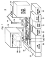
- FIGS 1 to 4 are explanatory views of the configuration of an electrophoresis device 10 according to an embodiment of the present invention.
- the electrophoresis device 10 includes a temperature gradient tank 12, a dispenser 14, a holder storage cabinet 16, a photographing unit 18, a polymerase chain reaction (PCR) device 20, a chip rack 22, a chip disposal box 24, a DC power unit 26, a control unit 30, an arm 32, and a liquid feeder 34.
- PCR polymerase chain reaction
- a holder 100 formed with a thermally conductive material is put on the temperature gradient tank 12.
- a light transmissive cassette 150 is removably attached to the holder 100. Heat can be delivered to a gel side of the cassette 150 via the holder 100.
- the temperature gradient tank 12 is in contact with a bottom surface 106 of the holder 100.
- the temperature gradient tank 12 is provided to perform "temperature gradient electrophoresis", whereby a temperature gradient can be provided in a planar direction of the bottom surface 106. As a consequence, temperature distribution can be generated for the gel in the cassette 150.
- the dispenser 14 is for dispensing a DNA sample 204 to a gel 152.
- the dispenser 14 is mechanically and electrically coupled with the arm 32, so that movement of the dispenser 14, filling in the dispenser 14, and discharge by the dispenser 14 can be performed through the arm 32.
- the holder storage cabinet 16 houses a plurality of holders 100.
- the holder storage cabinet 16 includes a carrying device 16a.
- the carrying device 16a can send out the plurality of holders 100 housed in the holder storage cabinet 16 to a middle position of the temperature gradient tank 12 one by one.
- the carrying device 16a such as the structure of an actuator
- various kinds of publicly known carrying devices may suitably be used. Since the carrying devices including, for example, rails that hold the side surfaces of the holder and conveyors driven by a motor may be used, the detailed description of the carrying device 16a is omitted.
- the photographing unit 18 is placed above the holder 100 so as to overlook the holder 100 from the above.
- the photographing unit 18 includes an excitation light source 18a and a camera 18b.
- the excitation light source 18a is a light source for irradiating the stained DNA with excitation light through the cassette 150.
- the camera 18b can take an image through the cassette 150.
- the photographing unit 18 may be placed at positions where the holder 100 can be overlooked as and when necessary.
- the holder 100 may be configured to be movable on the temperature gradient tank 12 so that the holder 100 can be placed below the photographing unit 18 as and when necessary.
- the photographing unit 18 may be configured so as to be movable by means of a rail or the like and to be positioned above the holder 100 as and when necessary.
- the chip rack 22 houses a plurality of components called chips, which are attached to the dispenser 14 at the time of being used.
- a reagent rack 23 is to set a reagent for use in performing electrophoresis.
- the reagent is what is called a loading buffer.
- the DNA sample 204 and this reagent are mixed, and the mixture is dispensed to the gel 152. This makes it possible to prevent diffusion of the DNA sample 204 and to thereby stabilize the DNA sample 204 when the DNA sample 204 is dispensed to the gel 152.
- the chip disposal box 24 is a storage cabinet which houses used chips.
- the DC power unit 26 is for outputting a DC voltage for electrophoresis.
- the DC power unit 26 includes a pair of output terminals 26a and 26b. When the holder 100 is sent out onto the temperature gradient tank 12, the output terminals 26a and 26b are precisely connected to the electrode terminals 121 and 123 of the holder 100.
- the liquid feeder 34 includes, in its interior, a migration solution tank, a staining solution tank, a mixer to mix the migration solution and the staining solution, and a pump.
- the liquid feeder 34 can feed the migration solution and the staining solution to prescribed positions of the holder 100 via pipelines 36a and 36b.
- the control unit 30 can control the carrying device 16a of the holder storage cabinet 16.
- the control unit 30 can control the carrying device 16a to send out the holder 100 one by one.
- the control unit 30 is connected to the arm 32.
- the control unit 30 can control the dispenser 14 via the arm 32 to execute sucking operation, stirring operation, placing operation, and discharge operation.
- the sucking operation is the operation wherein the dispenser 14 attaches a chip in the chip rack 22 to itself and sucks the DNA sample 204 from the PCR device 20.
- the stirring operation is the operation wherein the dispenser 14 repeats suction and discharge to mix the DNA sample 204 sucked from the PCR device 20 with the reagent in the reagent rack 23.
- the placing operation is the operation to move the dispenser 14 to a prescribed position of the reagent rack 23 and/or a prescribed position in the holder 100 on the temperature gradient tank 12 for stirring operation.
- the discharge operation is the operation wherein the dispenser 14 discharges the DNA sample 204, which was mixed with the reagent in the chip that is attached to the dispenser 14, at a prescribed position in the holder 100.
- the control unit 30 is connected with the liquid feeder 34. By controlling the liquid feeder 34, the migration solution and the mixed liquid are fed to prescribed positions of the holder 100 via the pipelines 36a and 36b at predetermined timing.
- the control unit 30 is connected to the temperature gradient tank 12, the excitation light source 18a and the camera 18b in the photographing unit 18, and to the DC power unit 26.
- the control unit 30 can perform temperature gradient electrophoresis for a predetermined period of time by giving a predetermined temperature gradient to the holder 100 while applying a given direct current voltage from the DC power unit 26. After the electrophoresis is performed for the predetermined period of time, the control unit 30 irradiates the gel 152 with excitation light through the cassette 150, and takes an image with the camera 18b.
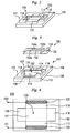
- Figure 2 is a perspective view for describing the configuration of the holder 100 and the cassette 150 according to the embodiment of the present invention
- Figure 3 is an exploded perspective view of Figure 2.
- Figure 4 is a plan view for describing the configuration of the holder 100 and the cassette 150 according to the embodiment of the present invention.
- the cassette 150 is made up of a pair of transparent plates 154 and 156.
- the transparent plates 154 and 156 which are formed of glass or light transmissive resin, can deliver heat to the gel 152 held therebetween.
- a penetrating groove 154a is provided on the transparent plate 154 positioned on the upper side. Part of the gel 152 is exposed from the penetrating groove 154a.
- the holder 100 includes a holder body 102 including an upper surface 104 and a bottom surface 106.
- the holder body 102 is formed of glass or light transmissive resin and has thermal conductivity to conduct the heat received on the bottom surface 106 to the cassette 150.
- a recess portion 110 is provided on the upper surface 104 of the holder body 102.
- the recess portion 110 is a hollow having a cross like outline as a whole. The depth of the recess portion 110 is made equal to or more than the thickness of the entire cassette 150 with the gel 152 held therein.
- the recess portion 110 has a central portion 111 positioned in the middle of the cross like outline.
- the recess portion 110 is provided with liquid supply portions 112 and 114 and frame portions 116 and 118 provided around the central portion 111 at positions perpendicular to each other in a plane view.
- the frame portions 116 and 118 have the same outline as the cassette 150, so that the cassette 150 can be fitted therein.
- the liquid supply portions 112 and 114 are members protruding outward from the frame portions 116 and 118.
- the liquid supply portions 112 and 114 form a space to contain liquid when the cassette 150 is fitted in the recess portion 110.
- the recess portion 110 is provided with electrodes 120 and 122 electrically insulated from each other.
- the electrodes 120 and 122 are exposed to the liquid supply portions 112 and 114 when the cassette 150 is set.
- the electrodes 120 and 122 are coupled with the electrode terminals 121 and 123, and the electrode terminals 121 and 123 are coupled to the DC power unit 26.
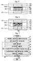
- Figures 5 and 6 are explanatory views of the electrophoresis method and a method for using an electrophoresis device according to the embodiment of the present invention.
- Figures 5 and 6 illustrate the cassette 150 before and after electrophoresis as viewed from the above, respectively.
- the cassette 150 with the gel 152 held therein is attached to the holder 100.
- the migration solution 200 is injected to the liquid supply portion 112, and the mixed liquid 202 is injected to the liquid supply portion 114.
- the mixed liquid 202 is formed by mixing the migration solution 200 with the staining solution.
- the electrode terminals 121 and 123 are coupled with the DC power unit 26 to provide a positive potential to the electrode 120 and a negative potential to the electrode 122. Accordingly, a DC voltage is applied to between the electrodes 120 and 122, and an electric current passes to the migration solution 200 and the mixed liquid 202. As a result, electrophoresis of the DNA sample 204 is performed.
- the staining solution and the migration solution are mixed before electrophoresis is started.
- a charged staining solution is used as the staining solution.
- positively charged staining solution may preferably be used. Using the positively charged staining solution causes the DNA and the staining solution to move in opposite directions during electrophoresis. As a result, the DNA and the staining solution are combined so that reliable staining of the DNA is conducted.
- any one of SYBR (registered trademark) DNA staining dye series including SYBR Green I, SYBR Green II, SYBR Gold, and SYBR Safe, may be used.
- SYBR Green I SYBR Green I
- SYBR Green II SYBR Green II
- SYBR Gold SYBR Safe
- YO Oxazole Yellow
- TO Thiazole Orange
- PG Pico (registered trademark) Green
- the temperature gradient tank 12 is controlled to generate a temperature gradient inside the surface of the gel 152. Accordingly, temperature gradient electrophoresis is performed. By performing the temperature gradient electrophoresis for a predetermined period of time, the DNA sample 204 moves as illustrated in Figure 6 . By analyzing this movement, DNA analysis can be conducted.
- Figure 7 is a flow chart for describing the electrophoresis method and the operation of the electrophoresis device according to the embodiment of the present invention.
- the electrophoresis device 10 is suitable for the electrophoresis method involving mixing of the migration solution and the staining solution. More specifically, the control unit 30 can control the carrying device 16a, the arm 32, the liquid feeder 34, the temperature gradient tank 12, the excitation light source 18a and the camera 18b in the photographing unit 18, and the DC power unit 26. Hereinbelow, control operation performed by the control unit 30 will also be described. The control unit 30 prestores a program for executing the following control operation in its internal memory.
- Step S1 First, the cassette 150 containing the gel 152 is prepared.
- the cassette 150 has light transmission that transmits excitation light and imaging light of the camera.
- the gel 152 has a planar body shape.
- the cassette 150 has the gel 152 held therein so as to expose the end portions 152a and 152b.
- Step S2 the cassette 150 is set in the holder 100.
- the plurality of holders 100 are prepared, and are housed at prescribed positions inside the holder storage cabinet 16. This enables the carrying device 16a to carry the plurality of holders 100 one by one, so that multiple analyzing operations can be performed continuously and automatically.
- Step S3 the holder 100 is carried to the middle position of the temperature gradient tank 12.
- this carrying operation is automatically performed by the carrying device 16a.
- Step S4 the DNA sample 204 is dispensed.
- the control unit 30 controls the dispenser 14 via the arm 32 to execute sucking operation, stirring operation, placing operation, and discharge operation.
- the DNA sample 204 is dispensed from the penetrating groove 154a, so that the DNA sample 204 is dispensed to the end face of the gel 152 on the side of the liquid supply portion 114, i.e., on the end portion 152b side.
- the DNA sample 204 is uniformly dispensed in parallel with the end portion 152b in an extending direction of the end portion 152b.
- step S4 dispensation of the DNA sample 204 in step S4 is implemented when the control unit 30 sends a control signal to the arm 32 as described in the foregoing. As a consequence, automatic dispensation of the DNA sample 204 can be achieved.
- Step S5 the migration solution and the staining solution are put in the holder 100. More specifically, the mixed liquid 202 is put into the liquid supply portion 112, and the migration solution 200 is put into the liquid supply portion 114. Accordingly, two facing portions in the end face of the gel 152, i.e., the end portions 152a and 152b are soaked in the migration solution. Then, the migration solution at least on one side of the end portion 152a and the end portion 152b is infused with the staining solution. According to this embodiment, only the migration solution 200 is put into the liquid supply portion 114, and the mixed liquid 202 formed by mixing the migration solution and the staining solution is put into the liquid supply portion 112. This provides a preparatory state wherein the end face of the gel containing a dispensed DNA is soaked in the mixed liquid 202.
- control unit 30 controls the liquid feeder 34, so that a specified amount of the migration solution 200 and the mixed liquid 202 is each fed to the liquid supply portions 112 and 114 by the pump inside the liquid feeder 34.
- Step S4 and step S5 may reversely be performed.
- Step S6 a DC voltage is applied to the migration solution to perform electrophoresis, while the temperature gradient tank 12 is controlled to provide a temperature gradient to the gel during electrophoresis.
- the staining solution is passed in the planar direction of the gel, and a temperature gradient is provided in the planar direction of the gel.
- control unit 30 controls the temperature gradient tank 12 and the DC power unit 26, so that automatic electrophoresis is performed under predetermined conditions (predetermined temperature inclination, predetermined applied voltage, and predetermined time).
- Step S7 After electrophoresis is performed, the gel 152 is irradiated with excitation light and is imaged with the camera 18b. In this step, after electrophoresis is performed, the gel 152 is irradiated with excitation light through the cassette 150, and is imaged with the camera 18b. In order to avoid a reflection problem, the direction of the excitation light source 18a may be adjusted to irradiate the gel 152 with inclined excitation light. In the electrophoresis device 10, the control unit 30 controls the excitation light source 18a and the camera 18b, so that the operation of step S7 is automatically implemented.
- Step S8 When the process of step S7 is completed, it is determined whether or not the current DNA analysis operation is finished. If one analysis operation is scheduled this time, the current routine is ended. If multiple analysis operations are scheduled, subsequent analysis operations are similarly performed by using other holders 100 until the scheduled number of analysis operations are finished.
- the holder 100 of this time is removed manually or automatically by another machine, and then the carrying device 16a sends out a new holder 100. As a result, replacement of the holder 100 is performed, and the control operation of steps S3 to S8 is repeated.
- electrophoresis and staining of the DNA are collectively performed, while the charged staining solution is injected into the gel with the driving force of electrophoresis, so that sufficient staining can be achieved. Therefore, the difficulty in operation can be reduced, while sufficient staining is implemented.
- the present embodiment provides the electrophoresis device 10 which automates the electrophoresis method according to the present embodiment.
- the gel has a thin planar body, so that an accurate temperature gradient can easily be provided. Therefore, the method is suitable for temperature gradient electrophoresis.
- the staining solution which obtained driving force by the electrophoresis infiltrates into the gel. Accordingly, even in the case of a thin planar gel, the staining solution can sufficiently impregnate the gel in its planar direction.
- sufficient staining can be implemented without removing the gel from the cassette. Accordingly, the difficulty in operation of removing the cassette is eliminated. Furthermore, the gel can be irradiated with excitation light through the cassette and be imaged with a camera. In addition, electrophoresis and staining can be performed in one process, so that the process can be simplified and the speed thereof can be increased.
- staining with the staining solution is performed in analysis operation, so that analysis accuracy and reliability of analysis results are high.
- analysis accuracy and the like are questionable.
- the present embodiment has high superiority.
- the electrophoresis method according to the present embodiment characterized as described before is also adequate for what is called a hyper detection of infectious disease based on genome profiling (HDGP) method as disclosed in Non Patent Document 1 described above.
- HDGP genome profiling
Landscapes
- Health & Medical Sciences (AREA)
- Life Sciences & Earth Sciences (AREA)
- Chemical & Material Sciences (AREA)
- Molecular Biology (AREA)
- Physics & Mathematics (AREA)
- General Health & Medical Sciences (AREA)
- Immunology (AREA)
- Electrochemistry (AREA)
- Analytical Chemistry (AREA)
- Biochemistry (AREA)
- Pathology (AREA)
- General Physics & Mathematics (AREA)
- Chemical Kinetics & Catalysis (AREA)
- Spectroscopy & Molecular Physics (AREA)
- Apparatus Associated With Microorganisms And Enzymes (AREA)
- Investigating Or Analysing Biological Materials (AREA)
- Investigating, Analyzing Materials By Fluorescence Or Luminescence (AREA)
- Investigating Or Analysing Materials By Optical Means (AREA)
- Measuring Or Testing Involving Enzymes Or Micro-Organisms (AREA)
- Automatic Analysis And Handling Materials Therefor (AREA)
Abstract
Description
- The present invention relates to an electrophoresis method and an electrophoresis device.
- Various kinds of electrophoretic techniques disclosed in the following Patent Literatures have conventionally been known for example. Techniques of using electrophoresis to analyze proteins and DNA are publicly known, including an imaging technique disclosed in
Patent Literature 3.Patent Literature 4 discloses analytical reagents relevant to proteins and the like. -
-
Patent Literature 1
Japanese Patent No. 2569474 -
Patent Literature 2
Japanese Patent Laid-Open No. 2004-286453 -
Patent Literature 3
Japanese Patent No. 4424938 -
Patent Literature 4
Japanese Patent Laid-Open No. 2010-14673 - Yoshinori Hatakeyama, Keiichi Hamano and Hidetoshi Iwano, (2008), An Ultimate Method for Detection of Infected Pathogenic Microoganism from Silkworm using HDGP, Journal of Insect Biotechnology and Sericology 77, 1-7
- Electrophoresis is used for analysis of deoxyribonucleic acid (DNA). The process of the analysis is as described below. First, a cassette containing gel is prepared. Then the cassette is set in a holder, and a DNA sample is dispensed to the gel. Then, the gel is soaked in a migration liquid and a DC voltage is applied thereto to perform electrophoresis. The electrophoresis disperses the DNA sample to each position on the gel. By observing the dispersed DNA sample, analysis of the DNA is implemented.
- Here, when electrophoresis is performed on a DNA sample which is not stained, the sample is stained with a stain solution after electrophoresis. After the DNA sample is stained, the DNA sample is irradiated with excitation light to generate fluorescent light. As a result, DNA is observed from the outside.
- In order to smoothly spread the stain solution into the gel to achieve sufficient staining, the gel is generally taken out from the cassette after electrophoresis and is soaked in the stain solution in an exposed state. However, to take out the gel from the cassette, it is necessary to carefully remove the gel from the surface of the cassette. This operation entails a very precise and delicate work, which requires mature technique. That is one of the factors that make the operation difficult.
- The present invention has been made to solve the above-stated problem. Accordingly, an object of the present invention is to provide an electrophoresis method and an electrophoresis device which can reduce the difficulty in operation while implementing sufficient straining.
- An electrophoresis method according to one aspect of the present invention includes:
- a preparation step of providing a preparatory state wherein an end face of a gel that contains dispensed DNA is soaked in a mixed liquid containing a migration solution and a charged staining solution; and
- an electrophoresis step of performing electrophoresis by applying a DC voltage to the mixed liquid in the preparatory state and supplying the charged staining solution to an inside of the gel from the end face of the gel.
- The electrophoresis method according to the above aspect, a temperature gradient may be provided to the gel during electrophoresis.
- The electrophoresis method according to the above aspect may further includes:
- an analysis step of irradiating the gel with excitation light after the electrophoresis and imaging the gel with a camera, wherein
- the preparation step includes: preparing a light transmissive cassette that transmits the excitation light and the imaging light of the camera; holding the gel having a planar body shape inside the cassette to expose the end face of the gel; and soaking two facing portions of the end face in the migration liquid, while infusing the staining solution into the migration liquid at least on one side of the two portions, and
- the electrophoresis step includes applying a voltage to the migration solution having the two portions soaked therein to pass the staining solution to a planar direction of the gel and to provide a temperature gradient to the planar direction of the gel.
- The electrophoresis method according to the above aspect may be such that, after the electrophoresis step, the gel is irradiated with the excitation light through the cassette while the gel is held in the cassette, and the gel is imaged with the camera.
- An electrophoresis device according to other aspect of the present invention includes:
- a temperature gradient tank;
- a holder including a holder body having an upper surface, a recess portion provided on the upper surface to enable a light transmissive cassette to fit therein, an electrode provided on the recess portion, and an electrode terminal coupled to the electrode;
- a carrying device capable of sending out the plurality of holders onto the temperature gradient tank one by one;
- dispensation means including a dispenser and an arm joined to the dispenser;
- a liquid feeder that feeds a mixed liquid containing the migration solution and the staining solution;
- a DC power supply;
- a photographing unit including an excitation light source and a camera; and
- a control unit connected to the carrying device, the arm, the liquid feeding unit, the DC power supply, and the photographing unit, wherein
- the control unit continuously executes:
- first control performed for making the carrying device to carry the holder onto the temperature gradient tank;
- second control performed subsequent to the first control for making the dispenser to perform dispensing to the holder on the temperature gradient tank with the arm and making the liquid feeder to feed the mixed liquid to the recess portion;
- third control performed subsequent to the second control for generating a temperature gradient in the temperature gradient tank and applying a DC voltage to the electrode terminal from the DC power supply; and
- fourth control performed subsequent to the third control for irradiating the cassette with light from the excitation light source and imaging the cassette with the camera.
- The electrophoresis method according to the present invention can reduce the difficulty in operation while implementing sufficient straining.
- According to the electrophoresis device in the present invention, a device suitable for automatization of the electrophoresis method according to the present invention is provided.
-
-
Figure 1 is an explanatory view of the configuration of an electrophoresis device according to an embodiment of the present invention; -
Figure 2 is an explanatory view of the configuration of an electrophoresis device according to an embodiment of the present invention; -
Figure 3 is an explanatory view of the configuration of an electrophoresis device according to an embodiment of the present invention; -
Figure 4 is an explanatory view of the configuration of an electrophoresis device according to an embodiment of the present invention; -
Figure 5 is an explanatory view of the electrophoresis method and a method for using an electrophoresis device according to the embodiment of the present invention; -
Figure 6 is an explanatory view of the electrophoresis method and a method for using an electrophoresis device according to the embodiment of the present invention; and -
Figure 7 is an explanatory view of the electrophoresis method and an operation of an electrophoresis device according to the embodiment of the present invention. -
Figures 1 to 4 are explanatory views of the configuration of anelectrophoresis device 10 according to an embodiment of the present invention. As illustrated inFigure 1 , theelectrophoresis device 10 includes atemperature gradient tank 12, adispenser 14, aholder storage cabinet 16, a photographingunit 18, a polymerase chain reaction (PCR)device 20, achip rack 22, achip disposal box 24, aDC power unit 26, acontrol unit 30, anarm 32, and aliquid feeder 34. - A
holder 100 formed with a thermally conductive material is put on thetemperature gradient tank 12. Alight transmissive cassette 150 is removably attached to theholder 100. Heat can be delivered to a gel side of thecassette 150 via theholder 100. - The
temperature gradient tank 12 is in contact with abottom surface 106 of theholder 100. Thetemperature gradient tank 12 is provided to perform "temperature gradient electrophoresis", whereby a temperature gradient can be provided in a planar direction of thebottom surface 106. As a consequence, temperature distribution can be generated for the gel in thecassette 150. - The
dispenser 14 is for dispensing aDNA sample 204 to agel 152. Thedispenser 14 is mechanically and electrically coupled with thearm 32, so that movement of thedispenser 14, filling in thedispenser 14, and discharge by thedispenser 14 can be performed through thearm 32. - The
holder storage cabinet 16 houses a plurality ofholders 100. Theholder storage cabinet 16 includes a carryingdevice 16a. The carryingdevice 16a can send out the plurality ofholders 100 housed in theholder storage cabinet 16 to a middle position of thetemperature gradient tank 12 one by one. - As for the detailed configuration of the carrying
device 16a, such as the structure of an actuator, various kinds of publicly known carrying devices may suitably be used. Since the carrying devices including, for example, rails that hold the side surfaces of the holder and conveyors driven by a motor may be used, the detailed description of the carryingdevice 16a is omitted. - The photographing
unit 18 is placed above theholder 100 so as to overlook theholder 100 from the above. The photographingunit 18 includes anexcitation light source 18a and acamera 18b. Theexcitation light source 18a is a light source for irradiating the stained DNA with excitation light through thecassette 150. Thecamera 18b can take an image through thecassette 150. - The photographing
unit 18 may be placed at positions where theholder 100 can be overlooked as and when necessary. For example, theholder 100 may be configured to be movable on thetemperature gradient tank 12 so that theholder 100 can be placed below the photographingunit 18 as and when necessary. Or the photographingunit 18 may be configured so as to be movable by means of a rail or the like and to be positioned above theholder 100 as and when necessary. - The chip rack 22 houses a plurality of components called chips, which are attached to the
dispenser 14 at the time of being used. Areagent rack 23 is to set a reagent for use in performing electrophoresis. The reagent is what is called a loading buffer. TheDNA sample 204 and this reagent are mixed, and the mixture is dispensed to thegel 152. This makes it possible to prevent diffusion of theDNA sample 204 and to thereby stabilize theDNA sample 204 when theDNA sample 204 is dispensed to thegel 152. Thechip disposal box 24 is a storage cabinet which houses used chips. - The
DC power unit 26 is for outputting a DC voltage for electrophoresis. TheDC power unit 26 includes a pair ofoutput terminals holder 100 is sent out onto thetemperature gradient tank 12, theoutput terminals electrode terminals holder 100. - The
liquid feeder 34 includes, in its interior, a migration solution tank, a staining solution tank, a mixer to mix the migration solution and the staining solution, and a pump. Theliquid feeder 34 can feed the migration solution and the staining solution to prescribed positions of theholder 100 viapipelines - The
control unit 30 can control the carryingdevice 16a of theholder storage cabinet 16. Thecontrol unit 30 can control the carryingdevice 16a to send out theholder 100 one by one. - The
control unit 30 is connected to thearm 32. Thecontrol unit 30 can control thedispenser 14 via thearm 32 to execute sucking operation, stirring operation, placing operation, and discharge operation. The sucking operation is the operation wherein thedispenser 14 attaches a chip in thechip rack 22 to itself and sucks theDNA sample 204 from thePCR device 20. The stirring operation is the operation wherein thedispenser 14 repeats suction and discharge to mix theDNA sample 204 sucked from thePCR device 20 with the reagent in thereagent rack 23. The placing operation is the operation to move thedispenser 14 to a prescribed position of thereagent rack 23 and/or a prescribed position in theholder 100 on thetemperature gradient tank 12 for stirring operation. The discharge operation is the operation wherein thedispenser 14 discharges theDNA sample 204, which was mixed with the reagent in the chip that is attached to thedispenser 14, at a prescribed position in theholder 100. - The
control unit 30 is connected with theliquid feeder 34. By controlling theliquid feeder 34, the migration solution and the mixed liquid are fed to prescribed positions of theholder 100 via thepipelines - The
control unit 30 is connected to thetemperature gradient tank 12, theexcitation light source 18a and thecamera 18b in the photographingunit 18, and to theDC power unit 26. As a consequence, thecontrol unit 30 can perform temperature gradient electrophoresis for a predetermined period of time by giving a predetermined temperature gradient to theholder 100 while applying a given direct current voltage from theDC power unit 26. After the electrophoresis is performed for the predetermined period of time, thecontrol unit 30 irradiates thegel 152 with excitation light through thecassette 150, and takes an image with thecamera 18b. -
Figure 2 is a perspective view for describing the configuration of theholder 100 and thecassette 150 according to the embodiment of the present invention, andFigure 3 is an exploded perspective view ofFigure 2. Figure 4 is a plan view for describing the configuration of theholder 100 and thecassette 150 according to the embodiment of the present invention. - The
cassette 150 is made up of a pair oftransparent plates transparent plates gel 152 held therebetween. A penetratinggroove 154a is provided on thetransparent plate 154 positioned on the upper side. Part of thegel 152 is exposed from the penetratinggroove 154a. - The
holder 100 includes aholder body 102 including anupper surface 104 and abottom surface 106. Theholder body 102 is formed of glass or light transmissive resin and has thermal conductivity to conduct the heat received on thebottom surface 106 to thecassette 150. Arecess portion 110 is provided on theupper surface 104 of theholder body 102. Therecess portion 110 is a hollow having a cross like outline as a whole. The depth of therecess portion 110 is made equal to or more than the thickness of theentire cassette 150 with thegel 152 held therein. - The
recess portion 110 has acentral portion 111 positioned in the middle of the cross like outline. Therecess portion 110 is provided withliquid supply portions frame portions central portion 111 at positions perpendicular to each other in a plane view. Theframe portions cassette 150, so that thecassette 150 can be fitted therein. Theliquid supply portions frame portions liquid supply portions cassette 150 is fitted in therecess portion 110. Since theend portions gel 152 are exposed from theliquid supply portions liquid supply portions end portions - The
recess portion 110 is provided withelectrodes electrodes liquid supply portions cassette 150 is set. Theelectrodes electrode terminals electrode terminals DC power unit 26. -
Figures 5 and 6 are explanatory views of the electrophoresis method and a method for using an electrophoresis device according to the embodiment of the present invention.Figures 5 and 6 illustrate thecassette 150 before and after electrophoresis as viewed from the above, respectively. Thecassette 150 with thegel 152 held therein is attached to theholder 100. - In performing electrophoresis, the
migration solution 200 is injected to theliquid supply portion 112, and themixed liquid 202 is injected to theliquid supply portion 114. Themixed liquid 202 is formed by mixing themigration solution 200 with the staining solution. - Next, the
electrode terminals DC power unit 26 to provide a positive potential to theelectrode 120 and a negative potential to theelectrode 122. Accordingly, a DC voltage is applied to between theelectrodes migration solution 200 and themixed liquid 202. As a result, electrophoresis of theDNA sample 204 is performed. - The staining solution and the migration solution are mixed before electrophoresis is started. A charged staining solution is used as the staining solution. By performing the electrophoresis in such a state, the staining solution infiltrates into the
gel 152 together with the migration solution based on the principle of electrophoresis. As a result, electrophoresis and staining of theDNA sample 204 can collectively be performed. - Since the DNA is negatively charged, positively charged staining solution may preferably be used. Using the positively charged staining solution causes the DNA and the staining solution to move in opposite directions during electrophoresis. As a result, the DNA and the staining solution are combined so that reliable staining of the DNA is conducted.
- Specifically, any one of SYBR (registered trademark) DNA staining dye series including SYBR Green I, SYBR Green II, SYBR Gold, and SYBR Safe, may be used. Any one of YO (Oxazole Yellow), TO (Thiazole Orange), or PG (Pico (registered trademark) Green) may also be used.
- In this embodiment in particular, the
temperature gradient tank 12 is controlled to generate a temperature gradient inside the surface of thegel 152. Accordingly, temperature gradient electrophoresis is performed. By performing the temperature gradient electrophoresis for a predetermined period of time, theDNA sample 204 moves as illustrated inFigure 6 . By analyzing this movement, DNA analysis can be conducted. -
Figure 7 is a flow chart for describing the electrophoresis method and the operation of the electrophoresis device according to the embodiment of the present invention. - The
electrophoresis device 10 according to the present embodiment is suitable for the electrophoresis method involving mixing of the migration solution and the staining solution. More specifically, thecontrol unit 30 can control the carryingdevice 16a, thearm 32, theliquid feeder 34, thetemperature gradient tank 12, theexcitation light source 18a and thecamera 18b in the photographingunit 18, and theDC power unit 26. Hereinbelow, control operation performed by thecontrol unit 30 will also be described. Thecontrol unit 30 prestores a program for executing the following control operation in its internal memory. - (Step S1) First, the
cassette 150 containing thegel 152 is prepared. In this step, thecassette 150 has light transmission that transmits excitation light and imaging light of the camera. Thegel 152 has a planar body shape. Thecassette 150 has thegel 152 held therein so as to expose theend portions - (Step S2) Next, the
cassette 150 is set in theholder 100. The plurality ofholders 100 are prepared, and are housed at prescribed positions inside theholder storage cabinet 16. This enables the carryingdevice 16a to carry the plurality ofholders 100 one by one, so that multiple analyzing operations can be performed continuously and automatically. - (Step S3) Next, the
holder 100 is carried to the middle position of thetemperature gradient tank 12. In theelectrophoresis device 10 according to the present embodiment, this carrying operation is automatically performed by the carryingdevice 16a. - (Step S4) Next, the
DNA sample 204 is dispensed. As described in the foregoing, thecontrol unit 30 controls thedispenser 14 via thearm 32 to execute sucking operation, stirring operation, placing operation, and discharge operation. In the discharge operation, theDNA sample 204 is dispensed from the penetratinggroove 154a, so that theDNA sample 204 is dispensed to the end face of thegel 152 on the side of theliquid supply portion 114, i.e., on theend portion 152b side. TheDNA sample 204 is uniformly dispensed in parallel with theend portion 152b in an extending direction of theend portion 152b. - In the
electrophoresis device 10, dispensation of theDNA sample 204 in step S4 is implemented when thecontrol unit 30 sends a control signal to thearm 32 as described in the foregoing. As a consequence, automatic dispensation of theDNA sample 204 can be achieved. - (Step S5) Next, the migration solution and the staining solution are put in the
holder 100. More specifically, themixed liquid 202 is put into theliquid supply portion 112, and themigration solution 200 is put into theliquid supply portion 114. Accordingly, two facing portions in the end face of thegel 152, i.e., theend portions end portion 152a and theend portion 152b is infused with the staining solution. According to this embodiment, only themigration solution 200 is put into theliquid supply portion 114, and themixed liquid 202 formed by mixing the migration solution and the staining solution is put into theliquid supply portion 112. This provides a preparatory state wherein the end face of the gel containing a dispensed DNA is soaked in themixed liquid 202. - In the
electrophoresis device 10, thecontrol unit 30 controls theliquid feeder 34, so that a specified amount of themigration solution 200 and themixed liquid 202 is each fed to theliquid supply portions liquid feeder 34. - Step S4 and step S5 may reversely be performed.
- (Step S6) Next, a DC voltage is applied to the migration solution to perform electrophoresis, while the
temperature gradient tank 12 is controlled to provide a temperature gradient to the gel during electrophoresis. By applying a voltage to the migration solution in which theend portions - In the
electrophoresis device 10, thecontrol unit 30 controls thetemperature gradient tank 12 and theDC power unit 26, so that automatic electrophoresis is performed under predetermined conditions (predetermined temperature inclination, predetermined applied voltage, and predetermined time). - (Step S7) After electrophoresis is performed, the
gel 152 is irradiated with excitation light and is imaged with thecamera 18b. In this step, after electrophoresis is performed, thegel 152 is irradiated with excitation light through thecassette 150, and is imaged with thecamera 18b. In order to avoid a reflection problem, the direction of theexcitation light source 18a may be adjusted to irradiate thegel 152 with inclined excitation light. In theelectrophoresis device 10, thecontrol unit 30 controls theexcitation light source 18a and thecamera 18b, so that the operation of step S7 is automatically implemented. - (Step S8) When the process of step S7 is completed, it is determined whether or not the current DNA analysis operation is finished. If one analysis operation is scheduled this time, the current routine is ended. If multiple analysis operations are scheduled, subsequent analysis operations are similarly performed by using
other holders 100 until the scheduled number of analysis operations are finished. - In the
electrophoresis device 10, theholder 100 of this time is removed manually or automatically by another machine, and then the carryingdevice 16a sends out anew holder 100. As a result, replacement of theholder 100 is performed, and the control operation of steps S3 to S8 is repeated. - Then, once the number of analysis operations reaches the scheduled number of operations, the current routine is ended.
- According to the electrophoresis method in the embodiment described above, electrophoresis and staining of the DNA are collectively performed, while the charged staining solution is injected into the gel with the driving force of electrophoresis, so that sufficient staining can be achieved. Therefore, the difficulty in operation can be reduced, while sufficient staining is implemented.
- Moreover, the present embodiment provides the
electrophoresis device 10 which automates the electrophoresis method according to the present embodiment. - According to the electrophoresis method in the present embodiment described above, the gel has a thin planar body, so that an accurate temperature gradient can easily be provided. Therefore, the method is suitable for temperature gradient electrophoresis.
- It is difficult to achieve sufficient staining in a short period of time by simply soaking a thin gel held inside the cassette. However, according to the present embodiment, the staining solution which obtained driving force by the electrophoresis infiltrates into the gel. Accordingly, even in the case of a thin planar gel, the staining solution can sufficiently impregnate the gel in its planar direction.
- According to the present embodiment, sufficient staining can be implemented without removing the gel from the cassette. Accordingly, the difficulty in operation of removing the cassette is eliminated. Furthermore, the gel can be irradiated with excitation light through the cassette and be imaged with a camera. In addition, electrophoresis and staining can be performed in one process, so that the process can be simplified and the speed thereof can be increased.
- Moreover, according to the present embodiment, staining with the staining solution is performed in analysis operation, so that analysis accuracy and reliability of analysis results are high. In the case of using a DNA sample stained (labeled) before electrophoresis, analysis accuracy and the like are questionable. As compared with the above case, the present embodiment has high superiority.
- The electrophoresis method according to the present embodiment characterized as described before is also adequate for what is called a hyper detection of infectious disease based on genome profiling (HDGP) method as disclosed in
Non Patent Document 1 described above. -
- 10 electrophoresis device
- 12 temperature gradient tank
- 14 dispenser
- 16 holder storage cabinet
- 16a carrying device
- 18 photographing unit
- 18a excitation light source
- 18b camera
- 20 polymerase chain reaction (PCR) device
- 22 chip rack
- 23 reagent rack
- 24 chip disposal box
- 26 DC power unit
- 26a, 26b output terminal
- 30 control unit
- 32 arm
- 34 liquid feeder
- 36a, 36b pipeline
- 100 holder
- 102 holder body
- 104 upper surface
- 106 bottom surface
- 110 recess portion
- 111 central portion
- 112, 114 liquid supply portion
- 116 frame portions
- 120, 122 electrodes
- 121, 123 electrode terminal
- 150 cassette
- 152 gel
- 152a, 152b end portion
- 154 transparent plate
- 154a penetrating groove
- 200 migration solution
- 202 mixed liquid
- 204 DNA sample
Claims (5)
- An electrophoresis method, comprising:a preparation step of providing a preparatory state wherein an end face of a gel that contains dispensed DNA is soaked in a mixed liquid containing a migration solution and a charged staining solution; andan electrophoresis step of performing electrophoresis by applying a DC voltage to the mixed liquid in the preparatory state and supplying the charged staining solution to an inside of the gel from the end face of the gel.
- The electrophoresis method according to claim 1, wherein a temperature gradient is provided to the gel during electrophoresis.
- The electrophoresis method according to claim 2, comprising:an analysis step of irradiating the gel with excitation light after the electrophoresis and imaging the gel with a camera, whereinthe preparation step includes: preparing a light transmissive cassette that transmits the excitation light and the imaging light of the camera; holding the gel having a planar body shape inside the cassette to expose the end face of the gel; and soaking two facing portions of the end face in the migration liquid, while infusing the staining solution into the migration liquid at least on one side of the two portions, andthe electrophoresis step includes applying a voltage to the migration solution having the two portions soaked therein to pass the staining solution to a planar direction of the gel and to provide a temperature gradient to the planar direction of the gel.
- The electrophoresis method according to claim 3, wherein
after the electrophoresis step, the gel is irradiated with the excitation light through the cassette while the gel is held in the cassette, and the gel is imaged with the camera. - An electrophoresis device, comprising:a temperature gradient tank;a holder including a holder body having an upper surface, a recess portion provided on the upper surface to enable a light transmissive cassette to fit therein, an electrode provided on the recess portion, and an electrode terminal coupled to the electrode;a carrying device capable of sending out the plurality of holders onto the temperature gradient tank one by one;dispensation means including a dispenser and an arm joined to the dispenser;a liquid feeder that feeds a mixed liquid containing the migration solution and the staining solution;a DC power supply;a photographing unit including an excitation light source and a camera; anda control unit connected to the carrying device, the arm, the liquid feeding unit, the DC power supply, and the photographing unit, whereinthe control unit continuously executes:first control performed for making the carrying device to carry the holder onto the temperature gradient tank;second control performed subsequent to the first control for making the dispenser to perform dispensing to the holder on the temperature gradient tank with the arm and making the liquid feeder to feed the mixed liquid to the recess portion;third control performed subsequent to the second control for generating a temperature gradient in the temperature gradient tank and applying a DC voltage to the electrode terminal from the DC power supply; andfourth control performed subsequent to the third control for irradiating the cassette with light from the excitation light source and imaging the cassette with the camera.
Applications Claiming Priority (1)
| Application Number | Priority Date | Filing Date | Title |
|---|---|---|---|
| PCT/JP2013/062592 WO2014178107A1 (en) | 2013-04-30 | 2013-04-30 | Electrophoresis method and electrophoresis device |
Publications (3)
| Publication Number | Publication Date |
|---|---|
| EP2993466A1 true EP2993466A1 (en) | 2016-03-09 |
| EP2993466A4 EP2993466A4 (en) | 2017-01-11 |
| EP2993466B1 EP2993466B1 (en) | 2018-12-19 |
Family
ID=51843260
Family Applications (1)
| Application Number | Title | Priority Date | Filing Date |
|---|---|---|---|
| EP13883485.8A Not-in-force EP2993466B1 (en) | 2013-04-30 | 2013-04-30 | Electrophoresis device |
Country Status (6)
| Country | Link |
|---|---|
| US (1) | US9702850B2 (en) |
| EP (1) | EP2993466B1 (en) |
| JP (1) | JP6002318B2 (en) |
| KR (1) | KR20150092333A (en) |
| CN (1) | CN105026923A (en) |
| WO (1) | WO2014178107A1 (en) |
Families Citing this family (6)
| Publication number | Priority date | Publication date | Assignee | Title |
|---|---|---|---|---|
| KR102109177B1 (en) * | 2013-01-03 | 2020-05-12 | 대우조선해양 주식회사 | Multi-layered automatic welding method of memory reproducing type |
| JP2016211963A (en) * | 2015-05-08 | 2016-12-15 | システム・インスツルメンツ株式会社 | Electrophoretic gel preparation cassette and method for preparing electrophoretic gel |
| US11237131B2 (en) | 2015-05-20 | 2022-02-01 | ProteinSimple | Systems and methods for electrophoretic separation and analysis of analytes |
| CN107271419B (en) * | 2017-07-24 | 2020-06-19 | 左豫虎 | Gel dyeing scanning imaging device and dyeing imaging method thereof |
| KR20190051884A (en) * | 2017-11-07 | 2019-05-15 | (주)크레용테크놀러지즈 | Method and apparatus of staining biological matrix using electro-focusing |
| CN108970402A (en) * | 2018-07-16 | 2018-12-11 | 陈叶 | An improved medical electrophoresis structure |
Family Cites Families (22)
| Publication number | Priority date | Publication date | Assignee | Title |
|---|---|---|---|---|
| JPS5713346A (en) * | 1980-06-27 | 1982-01-23 | Joko:Kk | Full automatic electrophoresis apparatus of cassette type |
| JPS6082847A (en) * | 1983-10-13 | 1985-05-11 | Dai Ichi Pure Chem Co Ltd | Electrophoresis method and detection dye reagent used in it |
| JP2569474B2 (en) | 1985-11-29 | 1997-01-08 | 株式会社島津製作所 | Electrophoresis device |
| US4810348A (en) * | 1987-03-16 | 1989-03-07 | Helena Laboratories Corporation | Automatic electrophoresis apparatus and method |
| JPH0694676A (en) * | 1992-09-10 | 1994-04-08 | Olympus Optical Co Ltd | Automatic electrophoretic device |
| US5460709A (en) * | 1993-06-21 | 1995-10-24 | Helena Laboratories Corporation | Automatic electrophoresis method and apparatus |
| JP3574811B2 (en) * | 1994-07-22 | 2004-10-06 | 株式会社北里サプライ | Multi-stage temperature gradient transparent plate and electrophoresis apparatus for electrophoresis |
| AU5775696A (en) * | 1995-06-06 | 1996-12-24 | Beltronics Inc | Automatic protein and/or dna analysis system and method |
| US6277259B1 (en) * | 1998-04-24 | 2001-08-21 | Enterprise Partners Ii | High performance multidimensional proteome analyzer |
| US8264680B2 (en) | 1999-05-28 | 2012-09-11 | Yokogawa Electric Corporation | Biochip reader and electrophoresis system |
| JP3695631B2 (en) | 1999-05-28 | 2005-09-14 | 横河電機株式会社 | Electrophoresis device |
| JP2001165903A (en) * | 1999-12-13 | 2001-06-22 | Taitec Kk | Micro support plate for electrophoresis |
| JP2002048765A (en) * | 2000-08-03 | 2002-02-15 | Masabumi Youda | Sample introduction apparatus for horizontal gel electrophoresis apparatus, horizontal gel electrophoresis system, sample introduction method and sample collection method |
| US7261800B1 (en) * | 2002-08-26 | 2007-08-28 | Helena Laboratories | Automatic in situ electrophoresis method and apparatus |
| JP2004286453A (en) * | 2003-03-19 | 2004-10-14 | Aisin Seiki Co Ltd | Fluorescent reader |
| JP4424938B2 (en) | 2003-08-19 | 2010-03-03 | タイテック株式会社 | Microgel cassette for electrophoresis |
| DE112005003114T5 (en) * | 2004-12-06 | 2008-05-08 | Katayanagi Institute, Hachioji | Method of separating protein, method of staining protein and liquid protein stain, and protein staining kit for use in these methods |
| JP4822409B2 (en) * | 2005-10-19 | 2011-11-24 | 独立行政法人産業技術総合研究所 | Protein analysis method |
| EP2105736A1 (en) * | 2008-03-28 | 2009-09-30 | Novartis Ag | Analysis of DNA by means of cappillary electrophoresis |
| JP5182809B2 (en) | 2008-07-07 | 2013-04-17 | 独立行政法人産業技術総合研究所 | Protein analysis method and reagent |
| JP5249988B2 (en) * | 2010-05-07 | 2013-07-31 | 株式会社日立ハイテクノロジーズ | Nucleic acid amplification apparatus and nucleic acid test apparatus using the same |
| US8652316B1 (en) * | 2012-09-24 | 2014-02-18 | Major Science Co., Ltd. | Electrophoresis system with picture taking device |
-
2013
- 2013-04-30 WO PCT/JP2013/062592 patent/WO2014178107A1/en not_active Ceased
- 2013-04-30 US US14/652,583 patent/US9702850B2/en active Active
- 2013-04-30 KR KR1020157018839A patent/KR20150092333A/en not_active Ceased
- 2013-04-30 EP EP13883485.8A patent/EP2993466B1/en not_active Not-in-force
- 2013-04-30 JP JP2015514708A patent/JP6002318B2/en active Active
- 2013-04-30 CN CN201380074109.3A patent/CN105026923A/en active Pending
Also Published As
| Publication number | Publication date |
|---|---|
| KR20150092333A (en) | 2015-08-12 |
| US9702850B2 (en) | 2017-07-11 |
| EP2993466A4 (en) | 2017-01-11 |
| JPWO2014178107A1 (en) | 2017-02-23 |
| WO2014178107A1 (en) | 2014-11-06 |
| US20150346146A1 (en) | 2015-12-03 |
| JP6002318B2 (en) | 2016-10-05 |
| EP2993466B1 (en) | 2018-12-19 |
| CN105026923A (en) | 2015-11-04 |
Similar Documents
| Publication | Publication Date | Title |
|---|---|---|
| US9702850B2 (en) | Electrophoresis method and electrophoresis device | |
| JP5033642B2 (en) | Microfluidic device | |
| JP4441653B2 (en) | Automated two-dimensional electrophoresis apparatus and apparatus components | |
| US6656724B1 (en) | Apparatus for automatic implementation of chemical or biological methods | |
| CN1648670B (en) | Microchip processing method and device | |
| US9599590B2 (en) | Side-eluting molecular fractionator | |
| JP6285859B2 (en) | Automatic size selection of nucleic acids | |
| US20160109406A1 (en) | Pulse-field multiplex capillary electrophoresis system | |
| CN104713858A (en) | Automatic time-resolved fluorescence assay device and application method thereof | |
| JP5696300B1 (en) | Automatic electroimmuno-staining system | |
| US10401322B2 (en) | Biomolecule analyzer | |
| CN118435050A (en) | Electrophoresis system | |
| US7261800B1 (en) | Automatic in situ electrophoresis method and apparatus | |
| JP2005315758A (en) | Microchip analysis method and apparatus | |
| JP2004226408A (en) | Method and apparatus for observing reaction of specimen | |
| US20170299547A1 (en) | Capillary electrophoresis apparatus | |
| WO2014203306A1 (en) | Electrophoresis device and analysis method | |
| JP2020525766A (en) | Pulsed field multiplexed capillary electrophoresis system | |
| CN110412303B (en) | Method for sample analysis | |
| JP2014219218A (en) | Electrophoretic gel holder and electrophoretic method | |
| CN114397348A (en) | Full-automatic all-in-one of liquid-transfering electrophoresis | |
| JP5310605B2 (en) | Microchip electrophoresis method and apparatus | |
| TWI358539B (en) | Integrated electrophoresis device and operation th | |
| US20230313267A1 (en) | Electrophoretic Collection Device and Nucleic Acid Pretreatment Device | |
| JP2016211963A (en) | Electrophoretic gel preparation cassette and method for preparing electrophoretic gel |
Legal Events
| Date | Code | Title | Description |
|---|---|---|---|
| PUAI | Public reference made under article 153(3) epc to a published international application that has entered the european phase |
Free format text: ORIGINAL CODE: 0009012 |
|
| 17P | Request for examination filed |
Effective date: 20150710 |
|
| AK | Designated contracting states |
Kind code of ref document: A1 Designated state(s): AL AT BE BG CH CY CZ DE DK EE ES FI FR GB GR HR HU IE IS IT LI LT LU LV MC MK MT NL NO PL PT RO RS SE SI SK SM TR |
|
| AX | Request for extension of the european patent |
Extension state: BA ME |
|
| DAX | Request for extension of the european patent (deleted) | ||
| RIN1 | Information on inventor provided before grant (corrected) |
Inventor name: HATAKEYAMA, YOSHINORI Inventor name: SHIMURA, NOBUAKI Inventor name: UJIMA, YOSHIHISA |
|
| RIC1 | Information provided on ipc code assigned before grant |
Ipc: G01N 27/447 20060101AFI20161130BHEP |
|
| A4 | Supplementary search report drawn up and despatched |
Effective date: 20161208 |
|
| GRAP | Despatch of communication of intention to grant a patent |
Free format text: ORIGINAL CODE: EPIDOSNIGR1 |
|
| STAA | Information on the status of an ep patent application or granted ep patent |
Free format text: STATUS: GRANT OF PATENT IS INTENDED |
|
| INTG | Intention to grant announced |
Effective date: 20180711 |
|
| GRAS | Grant fee paid |
Free format text: ORIGINAL CODE: EPIDOSNIGR3 |
|
| GRAA | (expected) grant |
Free format text: ORIGINAL CODE: 0009210 |
|
| STAA | Information on the status of an ep patent application or granted ep patent |
Free format text: STATUS: THE PATENT HAS BEEN GRANTED |
|
| AK | Designated contracting states |
Kind code of ref document: B1 Designated state(s): AL AT BE BG CH CY CZ DE DK EE ES FI FR GB GR HR HU IE IS IT LI LT LU LV MC MK MT NL NO PL PT RO RS SE SI SK SM TR |
|
| REG | Reference to a national code |
Ref country code: GB Ref legal event code: FG4D |
|
| REG | Reference to a national code |
Ref country code: CH Ref legal event code: EP |
|
| REG | Reference to a national code |
Ref country code: IE Ref legal event code: FG4D |
|
| REG | Reference to a national code |
Ref country code: DE Ref legal event code: R096 Ref document number: 602013048602 Country of ref document: DE |
|
| REG | Reference to a national code |
Ref country code: AT Ref legal event code: REF Ref document number: 1079255 Country of ref document: AT Kind code of ref document: T Effective date: 20190115 |
|
| REG | Reference to a national code |
Ref country code: NL Ref legal event code: MP Effective date: 20181219 |
|
| PG25 | Lapsed in a contracting state [announced via postgrant information from national office to epo] |
Ref country code: BG Free format text: LAPSE BECAUSE OF FAILURE TO SUBMIT A TRANSLATION OF THE DESCRIPTION OR TO PAY THE FEE WITHIN THE PRESCRIBED TIME-LIMIT Effective date: 20190319 Ref country code: NO Free format text: LAPSE BECAUSE OF FAILURE TO SUBMIT A TRANSLATION OF THE DESCRIPTION OR TO PAY THE FEE WITHIN THE PRESCRIBED TIME-LIMIT Effective date: 20190319 Ref country code: LT Free format text: LAPSE BECAUSE OF FAILURE TO SUBMIT A TRANSLATION OF THE DESCRIPTION OR TO PAY THE FEE WITHIN THE PRESCRIBED TIME-LIMIT Effective date: 20181219 Ref country code: FI Free format text: LAPSE BECAUSE OF FAILURE TO SUBMIT A TRANSLATION OF THE DESCRIPTION OR TO PAY THE FEE WITHIN THE PRESCRIBED TIME-LIMIT Effective date: 20181219 Ref country code: LV Free format text: LAPSE BECAUSE OF FAILURE TO SUBMIT A TRANSLATION OF THE DESCRIPTION OR TO PAY THE FEE WITHIN THE PRESCRIBED TIME-LIMIT Effective date: 20181219 Ref country code: HR Free format text: LAPSE BECAUSE OF FAILURE TO SUBMIT A TRANSLATION OF THE DESCRIPTION OR TO PAY THE FEE WITHIN THE PRESCRIBED TIME-LIMIT Effective date: 20181219 |
|
| REG | Reference to a national code |
Ref country code: LT Ref legal event code: MG4D |
|
| REG | Reference to a national code |
Ref country code: AT Ref legal event code: MK05 Ref document number: 1079255 Country of ref document: AT Kind code of ref document: T Effective date: 20181219 |
|
| PG25 | Lapsed in a contracting state [announced via postgrant information from national office to epo] |
Ref country code: SE Free format text: LAPSE BECAUSE OF FAILURE TO SUBMIT A TRANSLATION OF THE DESCRIPTION OR TO PAY THE FEE WITHIN THE PRESCRIBED TIME-LIMIT Effective date: 20181219 Ref country code: AL Free format text: LAPSE BECAUSE OF FAILURE TO SUBMIT A TRANSLATION OF THE DESCRIPTION OR TO PAY THE FEE WITHIN THE PRESCRIBED TIME-LIMIT Effective date: 20181219 Ref country code: GR Free format text: LAPSE BECAUSE OF FAILURE TO SUBMIT A TRANSLATION OF THE DESCRIPTION OR TO PAY THE FEE WITHIN THE PRESCRIBED TIME-LIMIT Effective date: 20190320 Ref country code: RS Free format text: LAPSE BECAUSE OF FAILURE TO SUBMIT A TRANSLATION OF THE DESCRIPTION OR TO PAY THE FEE WITHIN THE PRESCRIBED TIME-LIMIT Effective date: 20181219 |
|
| PG25 | Lapsed in a contracting state [announced via postgrant information from national office to epo] |
Ref country code: NL Free format text: LAPSE BECAUSE OF FAILURE TO SUBMIT A TRANSLATION OF THE DESCRIPTION OR TO PAY THE FEE WITHIN THE PRESCRIBED TIME-LIMIT Effective date: 20181219 |
|
| PG25 | Lapsed in a contracting state [announced via postgrant information from national office to epo] |
Ref country code: ES Free format text: LAPSE BECAUSE OF FAILURE TO SUBMIT A TRANSLATION OF THE DESCRIPTION OR TO PAY THE FEE WITHIN THE PRESCRIBED TIME-LIMIT Effective date: 20181219 Ref country code: CZ Free format text: LAPSE BECAUSE OF FAILURE TO SUBMIT A TRANSLATION OF THE DESCRIPTION OR TO PAY THE FEE WITHIN THE PRESCRIBED TIME-LIMIT Effective date: 20181219 Ref country code: PT Free format text: LAPSE BECAUSE OF FAILURE TO SUBMIT A TRANSLATION OF THE DESCRIPTION OR TO PAY THE FEE WITHIN THE PRESCRIBED TIME-LIMIT Effective date: 20190419 Ref country code: PL Free format text: LAPSE BECAUSE OF FAILURE TO SUBMIT A TRANSLATION OF THE DESCRIPTION OR TO PAY THE FEE WITHIN THE PRESCRIBED TIME-LIMIT Effective date: 20181219 Ref country code: IT Free format text: LAPSE BECAUSE OF FAILURE TO SUBMIT A TRANSLATION OF THE DESCRIPTION OR TO PAY THE FEE WITHIN THE PRESCRIBED TIME-LIMIT Effective date: 20181219 |
|
| PG25 | Lapsed in a contracting state [announced via postgrant information from national office to epo] |
Ref country code: IS Free format text: LAPSE BECAUSE OF FAILURE TO SUBMIT A TRANSLATION OF THE DESCRIPTION OR TO PAY THE FEE WITHIN THE PRESCRIBED TIME-LIMIT Effective date: 20190419 Ref country code: SK Free format text: LAPSE BECAUSE OF FAILURE TO SUBMIT A TRANSLATION OF THE DESCRIPTION OR TO PAY THE FEE WITHIN THE PRESCRIBED TIME-LIMIT Effective date: 20181219 Ref country code: RO Free format text: LAPSE BECAUSE OF FAILURE TO SUBMIT A TRANSLATION OF THE DESCRIPTION OR TO PAY THE FEE WITHIN THE PRESCRIBED TIME-LIMIT Effective date: 20181219 Ref country code: SM Free format text: LAPSE BECAUSE OF FAILURE TO SUBMIT A TRANSLATION OF THE DESCRIPTION OR TO PAY THE FEE WITHIN THE PRESCRIBED TIME-LIMIT Effective date: 20181219 Ref country code: EE Free format text: LAPSE BECAUSE OF FAILURE TO SUBMIT A TRANSLATION OF THE DESCRIPTION OR TO PAY THE FEE WITHIN THE PRESCRIBED TIME-LIMIT Effective date: 20181219 |
|
| REG | Reference to a national code |
Ref country code: DE Ref legal event code: R097 Ref document number: 602013048602 Country of ref document: DE |
|
| PLBE | No opposition filed within time limit |
Free format text: ORIGINAL CODE: 0009261 |
|
| STAA | Information on the status of an ep patent application or granted ep patent |
Free format text: STATUS: NO OPPOSITION FILED WITHIN TIME LIMIT |
|
| PG25 | Lapsed in a contracting state [announced via postgrant information from national office to epo] |
Ref country code: DK Free format text: LAPSE BECAUSE OF FAILURE TO SUBMIT A TRANSLATION OF THE DESCRIPTION OR TO PAY THE FEE WITHIN THE PRESCRIBED TIME-LIMIT Effective date: 20181219 Ref country code: AT Free format text: LAPSE BECAUSE OF FAILURE TO SUBMIT A TRANSLATION OF THE DESCRIPTION OR TO PAY THE FEE WITHIN THE PRESCRIBED TIME-LIMIT Effective date: 20181219 |
|
| REG | Reference to a national code |
Ref country code: DE Ref legal event code: R119 Ref document number: 602013048602 Country of ref document: DE |
|
| 26N | No opposition filed |
Effective date: 20190920 |
|
| REG | Reference to a national code |
Ref country code: CH Ref legal event code: PL |
|
| REG | Reference to a national code |
Ref country code: BE Ref legal event code: MM Effective date: 20190430 |
|
| GBPC | Gb: european patent ceased through non-payment of renewal fee |
Effective date: 20190430 |
|
| PG25 | Lapsed in a contracting state [announced via postgrant information from national office to epo] |
Ref country code: LU Free format text: LAPSE BECAUSE OF NON-PAYMENT OF DUE FEES Effective date: 20190430 Ref country code: MC Free format text: LAPSE BECAUSE OF FAILURE TO SUBMIT A TRANSLATION OF THE DESCRIPTION OR TO PAY THE FEE WITHIN THE PRESCRIBED TIME-LIMIT Effective date: 20181219 |
|
| PG25 | Lapsed in a contracting state [announced via postgrant information from national office to epo] |
Ref country code: LI Free format text: LAPSE BECAUSE OF NON-PAYMENT OF DUE FEES Effective date: 20190430 Ref country code: CH Free format text: LAPSE BECAUSE OF NON-PAYMENT OF DUE FEES Effective date: 20190430 Ref country code: DE Free format text: LAPSE BECAUSE OF NON-PAYMENT OF DUE FEES Effective date: 20191101 Ref country code: GB Free format text: LAPSE BECAUSE OF NON-PAYMENT OF DUE FEES Effective date: 20190430 |
|
| PG25 | Lapsed in a contracting state [announced via postgrant information from national office to epo] |
Ref country code: FR Free format text: LAPSE BECAUSE OF NON-PAYMENT OF DUE FEES Effective date: 20190430 Ref country code: BE Free format text: LAPSE BECAUSE OF NON-PAYMENT OF DUE FEES Effective date: 20190430 Ref country code: SI Free format text: LAPSE BECAUSE OF FAILURE TO SUBMIT A TRANSLATION OF THE DESCRIPTION OR TO PAY THE FEE WITHIN THE PRESCRIBED TIME-LIMIT Effective date: 20181219 |
|
| PG25 | Lapsed in a contracting state [announced via postgrant information from national office to epo] |
Ref country code: TR Free format text: LAPSE BECAUSE OF FAILURE TO SUBMIT A TRANSLATION OF THE DESCRIPTION OR TO PAY THE FEE WITHIN THE PRESCRIBED TIME-LIMIT Effective date: 20181219 |
|
| PG25 | Lapsed in a contracting state [announced via postgrant information from national office to epo] |
Ref country code: IE Free format text: LAPSE BECAUSE OF NON-PAYMENT OF DUE FEES Effective date: 20190430 |
|
| PG25 | Lapsed in a contracting state [announced via postgrant information from national office to epo] |
Ref country code: CY Free format text: LAPSE BECAUSE OF FAILURE TO SUBMIT A TRANSLATION OF THE DESCRIPTION OR TO PAY THE FEE WITHIN THE PRESCRIBED TIME-LIMIT Effective date: 20181219 |
|
| PG25 | Lapsed in a contracting state [announced via postgrant information from national office to epo] |
Ref country code: HU Free format text: LAPSE BECAUSE OF FAILURE TO SUBMIT A TRANSLATION OF THE DESCRIPTION OR TO PAY THE FEE WITHIN THE PRESCRIBED TIME-LIMIT; INVALID AB INITIO Effective date: 20130430 Ref country code: MT Free format text: LAPSE BECAUSE OF FAILURE TO SUBMIT A TRANSLATION OF THE DESCRIPTION OR TO PAY THE FEE WITHIN THE PRESCRIBED TIME-LIMIT Effective date: 20181219 |
|
| PG25 | Lapsed in a contracting state [announced via postgrant information from national office to epo] |
Ref country code: MK Free format text: LAPSE BECAUSE OF FAILURE TO SUBMIT A TRANSLATION OF THE DESCRIPTION OR TO PAY THE FEE WITHIN THE PRESCRIBED TIME-LIMIT Effective date: 20181219 |