JP2004226408A - Method and apparatus for observing reaction of specimen - Google Patents
Method and apparatus for observing reaction of specimen Download PDFInfo
- Publication number
- JP2004226408A JP2004226408A JP2004012940A JP2004012940A JP2004226408A JP 2004226408 A JP2004226408 A JP 2004226408A JP 2004012940 A JP2004012940 A JP 2004012940A JP 2004012940 A JP2004012940 A JP 2004012940A JP 2004226408 A JP2004226408 A JP 2004226408A
- Authority
- JP
- Japan
- Prior art keywords
- sample
- optical
- injection
- optical axis
- observation
- Prior art date
- Legal status (The legal status is an assumption and is not a legal conclusion. Google has not performed a legal analysis and makes no representation as to the accuracy of the status listed.)
- Withdrawn
Links
Images


Classifications
-
- G—PHYSICS
- G01—MEASURING; TESTING
- G01N—INVESTIGATING OR ANALYSING MATERIALS BY DETERMINING THEIR CHEMICAL OR PHYSICAL PROPERTIES
- G01N21/00—Investigating or analysing materials by the use of optical means, i.e. using sub-millimetre waves, infrared, visible or ultraviolet light
- G01N21/17—Systems in which incident light is modified in accordance with the properties of the material investigated
- G01N21/25—Colour; Spectral properties, i.e. comparison of effect of material on the light at two or more different wavelengths or wavelength bands
- G01N21/251—Colorimeters; Construction thereof
- G01N21/253—Colorimeters; Construction thereof for batch operation, i.e. multisample apparatus
-
- G—PHYSICS
- G01—MEASURING; TESTING
- G01N—INVESTIGATING OR ANALYSING MATERIALS BY DETERMINING THEIR CHEMICAL OR PHYSICAL PROPERTIES
- G01N21/00—Investigating or analysing materials by the use of optical means, i.e. using sub-millimetre waves, infrared, visible or ultraviolet light
- G01N21/62—Systems in which the material investigated is excited whereby it emits light or causes a change in wavelength of the incident light
- G01N21/63—Systems in which the material investigated is excited whereby it emits light or causes a change in wavelength of the incident light optically excited
- G01N21/64—Fluorescence; Phosphorescence
- G01N21/645—Specially adapted constructive features of fluorimeters
- G01N21/6452—Individual samples arranged in a regular 2D-array, e.g. multiwell plates
-
- G—PHYSICS
- G01—MEASURING; TESTING
- G01N—INVESTIGATING OR ANALYSING MATERIALS BY DETERMINING THEIR CHEMICAL OR PHYSICAL PROPERTIES
- G01N21/00—Investigating or analysing materials by the use of optical means, i.e. using sub-millimetre waves, infrared, visible or ultraviolet light
- G01N21/75—Systems in which material is subjected to a chemical reaction, the progress or the result of the reaction being investigated
- G01N21/76—Chemiluminescence; Bioluminescence
Abstract
Description
本発明は、独立請求項1と独立請求項22の前置きに各々対応する、試薬が加えられたサンプルを観察する装置と方法に関する。この場合、このサンプルの反応を観察する装置は、第1の光学軸の方向において、第1の光学軸に貫かれる第1の観察領域内でサンプルを観察する少なくとも1つの第1の光学装置;サンプルが入った容器を受けて、第1の光学軸に対してこれらの容器に入ったサンプルが1列に整列する1つの第1の装置、および液体をサンプルへ加える注入装置を含む。この場合、注入装置は、第1の光学装置の観察領域に位置する少なくとも1つの注入針の注入口、および少なくとも1つの関連する供給ラインを含む。
The present invention relates to an apparatus and a method for observing a sample to which a reagent has been added, corresponding to the preambles of
関連する技術分野で長い間知られているこの種の装置は、試薬を混ぜたサンプルの発光を計測することに基づいている。発光は、一般的にサンプルの化学反応の発生に帰する発光に関係する。これらの試薬が加えられたサンプルの反応を観察する装置は、第1の光学軸の方向へサンプルを観察する少なくとも1つの第1の光学装置を含む。加えて、そのような装置は、サンプルが中に入った容器を受けて、第1の光学軸に対してこれらの容器に入ったサンプルを1列に整列する第1の装置と、第1の光学軸に沿った上記サンプルおよび第1の光学装置の共通の整列した列とを含む。注入装置を使用して、液体および/または試薬が、与えられたサンプルに加えられる。注入装置は、この場合、第1の光学デバイスと容器の間に位置していて、少なくとも1つの第1の光学装置の観察領域に位置する注入針の注入口と、そこに位置する供給ラインとを含む。それ故、注入器は、そのような反応を開始するために使用されて、そのような反応は上記サンプルの発光を誘発する。この場合、注入器を提供される液体サンプルへ使用して、液体試薬のある特定の量が加えられる。例えば活性化溶液や、停止液などの液体は試薬と呼ばれる。この反応により誘発された発光の検出と記録の後で、上記サンプルは、第2の計測地点へ移動して、上記サンプルにより発せられる蛍光発光を誘発して、計測する。蛍光発光は、一般的に光源からのサンプルへの照射によるサンプルの発光を意味する;この場合、励起光の周波数は、典型的には上記サンプルにより発せられる蛍光発光の周波数と異なる。 This type of device, which has been known for a long time in the related technical field, is based on measuring the luminescence of a sample mixed with reagents. Luminescence generally relates to luminescence attributed to the occurrence of a chemical reaction in the sample. The apparatus for observing the reaction of the sample to which these reagents are added includes at least one first optical apparatus for observing the sample in the direction of the first optical axis. In addition, such an apparatus includes a first apparatus that receives containers containing samples therein and aligns the samples contained in these containers in a row with respect to a first optical axis; Including the sample along the optical axis and a common aligned row of first optical devices. Using an injection device, liquids and / or reagents are added to a given sample. The injection device is in this case located between the first optical device and the container, and the injection port of the injection needle located in the observation region of the at least one first optical device, and the supply line located there including. Therefore, an injector is used to initiate such a reaction, which triggers the sample to emit light. In this case, a certain amount of liquid reagent is added using an injector to the provided liquid sample. For example, a liquid such as an activation solution or a stop solution is called a reagent. After detection and recording of the luminescence induced by this reaction, the sample moves to a second measurement point to induce and measure the fluorescence emitted by the sample. Fluorescence emission generally refers to the emission of a sample upon irradiation of the sample from a light source; in this case, the frequency of the excitation light is typically different from the frequency of the fluorescence emission emitted by the sample.
上記サンプルの蛍光発光および/または発光は、サンプル自身の構造に起因する発光かもしれない。しかし、蛍光発光および/または発光は、上記関連する技術分野でよく知られた、または抗体やリガンドを使用してサンプル分子に結合される既知の物質を通じて対応する物質を、サンプルに混合することにより生成されるようにサンプルに加えられた特性である。関連した技術で知られている装置を利用してでは、上記サンプルと試薬との反応に誘発される発光と、励起光による上記サンプルへの照射により誘発される蛍光発光とを同時には探知不可能である。 The fluorescence emission and / or emission of the sample may be emission due to the structure of the sample itself. However, fluorescence and / or luminescence can be achieved by mixing the corresponding substance into the sample through known substances that are well known in the relevant technical field or bound to the sample molecule using antibodies or ligands. A property added to the sample to be generated. Using a device known in the related art, it is impossible to simultaneously detect light emission induced by the reaction between the sample and the reagent and fluorescence light emission induced by irradiation of the sample with excitation light. It is.
加えて、関連する技術で知られている装置においては、注入器の設定および/または取替えは、ハウジングが開いているときのみ実行してよい。注入器および/または注入針は、この注意を要する作業の間に被害を受けるかもしれない。 In addition, in devices known in the relevant art, the injector setting and / or replacement may only be performed when the housing is open. The injector and / or injection needle may be damaged during this sensitive operation.
それ故、本発明の目的は、試薬が混ぜられて励起光を使用して照射されたサンプルの発光および/または蛍光発光が測定されて、その装置内に注入器および/または注入針が位置し容易に交換できる1つの装置を提案することである。 Therefore, the object of the present invention is to measure the luminescence and / or fluorescence emission of a sample that has been mixed with reagents and irradiated using excitation light, and the injector and / or injection needle is located within the device. Propose one device that can be easily replaced.
この目的は独立請求項1の特徴により達成される。本発明の有利な改良と追加の特徴は従属請求項に起因する。
This object is achieved by the features of
本発明の利点は以下を含む。
‐試薬と混合するサンプルの全体的な反応速度、および、それに関連する発光の強度と分布は、サンプルまたは検出器の移動をともなわずに、サンプルの励起および蛍光発光の計測と同時に記録されてもよい。
‐例えばもしマイクロプレートの96、384、1536のくぼみに受けられた全てのサンプルが、蛍光発光と発光とを同時に検査されるとすると、これは、各々が蛍光発光および/または発光を検出する2つの隣りあったくぼみの距離だけ、共有する光学軸に対してマイクロプレートが移動されなければならないという点で実行される。蛍光発光を検出する光学装置の位置から、発光を検出する光学装置の位置への、マイクロプレートの時間を浪費する前後の動きはなしで済まされて、特に1536のくぼみのマイクロプレートでは‐莫大な時間の節約を表わす。
‐注入器および/または注入針は装置から取り外されてもよくて、再びそこへ戻されてもよくて、損傷から守られている。
‐実験を行う前に注入器および/または注入針は、装置外でいずれの方法でも(例えば汚染を通して)装置を損傷させずに完全に機能するように、検査されて、洗浄されて、試験される。
‐注入器および/または注入針を受けて、保護するトレーが、上記サンプルの発光を観察する領域を定義する目的で使用される。
The advantages of the present invention include:
-The overall reaction rate of the sample mixed with the reagent, and the intensity and distribution of the emission associated therewith, can be recorded simultaneously with the sample excitation and fluorescence measurements without sample or detector movement. Good.
-For example, if all samples received in the recesses 96, 384, 1536 of the microplate are examined for fluorescence and luminescence at the same time, this means that each detects fluorescence and / or
The injector and / or injection needle may be removed from the device and may be returned to it and protected from damage.
-Prior to conducting the experiment, the injector and / or needle should be inspected, cleaned and tested out of the device in any way (e.g. through contamination) so that it is fully functional without damaging the device. The
-A tray that receives and protects the injector and / or injection needle is used to define the region in which the emission of the sample is observed.
以下、添付の図を参照して発明の実施の形態を説明する。 Hereinafter, embodiments of the present invention will be described with reference to the accompanying drawings.
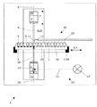
図1は、第1の実施の形態による試薬3が加えられたサンプル2の反応を観察するための装置1を示している。この装置は、第1の光学軸5の方向と、上記第1の光学軸で貫かれる第1の観察領域6とにある、サンプル2を観察する第1の光学装置4を含む。観察領域6は、好ましくは、96、384、または1536のくぼみをもつマイクロプレートのくぼみの内側に正確に対応する。加えて、上記装置は、サンプル2が中に入った容器8を受けるように、および第1の光学軸5に対してこれらの容器に入ったサンプルを1列に整列するように、第1の装置7を含む。特に好ましい容器は上記マイクロプレートであって、装置の中で本質的に水平方向に整列して、多数のサンプルを自動的に処理することを可能にする。第2の装置9は、第1の光学軸5に沿った、サンプル2と第1の光学装置4に共通の整列した列で導入される。この第1の光学軸は好ましくは垂直Z方向で動作する。
FIG. 1 shows an
注入装置10はサンプル2に液体3を加えるために使用される。この注入装置は、好ましくは第1の光学装置4と容器8の間に位置して、第1の光学装置4の観察領域6に位置する注入針12および注入器の少なくとも1つの注入口11を含んで、供給ライン13はそこに配置される。
The
本発明による装置1は、好ましくは、第2の光学軸によって貫かれる、第2の光学軸15の方向と、第2の観察領域16でサンプル2を観察する第2の光学装置14も含む。加えて、本発明による装置1は、第1の波長の励起光でサンプル2を照射する発光装置17を含む。この目的のため、フラッシュランプ17’の光は、好ましくは、第2の光学軸15の光線が通る道に位置するダイクロイックミラーにより上記サンプル2上に偏光される。次に、上記サンプルの蛍光発光の光は、ダイクロイックミラー17”を通して第2の光学装置14の蛍光発光検出器31に達する。注入装置10とサンプル2の入った容器8とは、2つの光学装置4、14の間に位置する。2つの観察領域6、16は本質的に同時に起こり、2つの光学軸5、15は反対の方向へ本質的に互いに平行なように動作する。2つの光学軸5、15は、互いに同一であることが望ましくて、本質的に縦で動作する。第1の光学装置4が上記サンプル2により発せられる発光を検出するために導入されて、第2の光学装置14が上記サンプル2より発せられる蛍光発光を検出するために導入される装置1が特に好ましい。
The
サンプル2が中に入った容器8を受けて、第1の光学軸5に対してこれらの容器8に入ったサンプル2を1列に整列する第1の装置7は、容器8を運ぶ受け部18を含む。この目的のため、この受け部は、XおよびY方向の水平平面上を移動可能なように導入された。本質的に水平なX‐Y領域のこの動きは、メカニカルステージと同様な受け部の装置を使用して、およびモーター駆動(図には示されていない)を通じて実行されることが好ましい。受け部18は、励起光が下からサンプルに達するように、およびこのように誘発されたサンプルの蛍光発光が、蛍光発光検出器31をもった第2の光学装置14に達する。
The first device 7 for receiving the
装置1は、好ましくは、つり下げ部21の第1の光学軸5に沿って、上記サンプル2と第1の光学装置4とに共通の整列した列の第2の装置9を含む。第1の光学装置4はその第2の装置に取り付けられているので、垂直のZ方向に移動可能である。それ故、図1が示すように、第1の光学装置4は、Zの方向(矢印)に移動可能であって、容器8を運ぶ受け部18の上に位置するが、第2の光学装置14は、好ましくは移動不可能なように固定されて、受け部18の下に位置する。
The
本発明の特に好ましい第2の実施の形態は図2および図3で示されている。第1の実施の形態の要素がすでに説明されているにもかかわらず、サンプル2へ液体3を加えるこの装置の注入装置10はトレー24を含み、少なくとも1つの注入針12と供給ライン13を運んで、位置決めするために導入される。上記注入装置10は、特に好ましくは3つの注入針12を持ち、各々が注入口11と供給ライン13をもつ。この場合、2つの注入口11が、96のくぼみのマイクロプレートに調整された第1の観察領域25で、互いに隣り合って位置して、第3の注入口11は、384のくぼみのマイクロプレート(図3の上面図を参照)に調整された第2の観察領域26に位置する。
A particularly preferred second embodiment of the invention is shown in FIGS. Although the elements of the first embodiment have already been described, the
図3に示されたものの代わりに、2つの注入針12は、384のくぼみのマイクロプレートに調整された第2の観察領域26で、互いに隣に位置してもよくて、3本より多いか少ない注入針12(例えば1、2、または4本の針)がトレー24上に置かれてもよい。加えて、例えば、3本か4本の注入針12が観察領域25の1つに、または複数の観察領域(図には示されていない)各々に位置してもよい。
Instead of the one shown in FIG. 3, the two injection needles 12 may be located next to each other in a
この第2の実施の形態は、好ましくは、ビーム・スプリッタ・スライド22と光ファイバー23をもつ照明装置を含んでいて、その光ファイバー経由でビーム・スプリッタ・スライド22が第2の光学装置14に接続される(図2参照)。この発光装置は光源17’(例えばフラッシュランプ)を含み、その光源からの励起光は、好ましくは、第2の光学軸15の光線の通り道に位置する鏡22”を経由して上記サンプル2上へ偏向される。2つの観察領域25、26は、注入装置10のトレー24の口により、および/またはトレー24の下に位置するスクリーン27により定義される。図2に示されているように、スクリーン27が導入されてもよいので、スクリーン27はXまたはYの方向へモーターにより移動されてもよくて、トレー24と上記サンプル2の間(実線で示されている)か、受け部18と第2の光学装置14の間(点線で示されている)に位置する。トレー24自身の底に取り付けられた1つのスクリーン(図には示されていない)も提供されてよくて、スクリーンの使用が完全に免除されてもよい。
This second embodiment preferably includes an illuminator having a
注入装置10のトレー24は、好ましくは第1の光学装置4に接続されていて、取り付けられているので、その高さは、本発明の装置1のこの第2の実施の形態により調整可能である。注入装置10のトレー24は装置1のハウジング部品28に取り付けられていてもよくて、ハウジング部品28に取り付けられているのでその上で高さが調整可能である。この場合、第1の光学装置4を使用した注入装置10の高さを設定するために、注入装置10のトレー24は、好ましくは第1の光学装置4と装置1のハウジング部品28とに弾力的に取り付けられている。特にユーザ・フレンドリーな装置1の種類は、注入針12をもったトレー24が装置1のハウジング部品28に取り付けられているので、スナップで取り付けられるおよび/または引き抜かれてもよい。好ましくは、トレー24は、第1の光学装置4に取り付けられていて、ともにZの方向へ調整可能である。
The
上記の全ての実施の形態による装置1は、このようにはるかに望ましく保護用シールド29を含んで、例えばX方向またはY方向に、注入装置10と第2の光学装置14の間に移動可能なように位置して、ある位置の第2の光学装置14を覆う。これは、容器8および/またはマイクロプレート20の取替え時に、保護用シールド29がいつも第2の光学装置14を覆うように位置してもよいという利点をもっている。保護用シールドを使用することにより、注入口11から繊細な第2の光学装置14への液体の意図しない滴りがうまく防がれる。
The
装置1のどの構成部品も蛍光発光および/または発光の検出への干渉する影響をもたないために、注入針12および/または少なくともその部品が観察領域25、26の中へのびていて、2つの光学装置4、14は、好ましくはそれ自体が発光や蛍光発光しない物質を含むおよび/または表面をもつ。そのような表面は、例えばテフロン(アメリカ合衆国、ウィルミントンのデュポン社の登録商標)などをもつ適切な被膜をもつか、機械的に粗くしてもよい(例えばブラシをかけられるか砂吹き機で磨かれるか)。加えて、注入装置10は、少なくとも3つの注入針12とトレー24を含む。および/または観察領域25、26を定義する少なくともその一部が、発光や蛍光発光しない物質を含みおよび/または発光や蛍光発光しない表面をもつ。
Since no component of the
第1のまたは第2の実施の形態、またはそれらとは異なる1つの実施の形態により、装置1を使用して上記サンプル2の反応を観察する方法では、第1の光学軸5の方向へおよび第1の光学軸5により貫かれる観察領域6内で上記サンプル2を観察する少なくとも1つの第1の光学装置と、サンプル2が中に入った容器8を受けるおよび第1の光学軸5に対してこれらの容器8の中に入ったサンプル2を1列に整列する第1の装置7と、好ましくは第1の光学軸5に沿って上記サンプル2と第1の光学装置4との共通の整列した列に向かう第2の装置9と、サンプル2へ液体3を加える注入装置10とを含む。注入装置10は、好ましくは第1の光学装置4と容器8の間に位置して、第1の光学装置4と関連する供給ライン13の観察領域6に位置する供給針12の少なくとも1つの注入口11を含んで、本発明により、装置1が、好ましくは、第2の光学軸15の方向と第2の光学軸15により貫かれる第2の観察領域16内とでサンプル2を観察する第2の光学装置14、および第1の波長の励起光をサンプル2へ照射する発光装置17を含む。2つの光学装置4、14の間および2つの観察領域6、16の間に位置する注入装置10とサンプル2をもった容器8とは本質的に同時に発生して、2つの光学軸は互いに平行に反対の方向へのびる。
In the method of observing the reaction of the
本発明による方法は以下の動作ステップを含む。
‐液体3をサンプル2へ加えるために少なくとも1つの注入針12とその供給ライン13を運んで位置決めするよう導入される、トレー24を含む装置1の注入装置10を使用して試薬3をサンプル2へ加えるステップ
‐発光装置17を使用して、第1の波長の励起光で上記サンプル2を照射するステップ
‐2つの光学装置4、14を使用して、上記サンプル2の発光と蛍光発光を同時に記録するステップ
‐2つの光学装置4、14のうち1つでサンプル2の発光と蛍光発光を記録するステップ。
The method according to the invention comprises the following operational steps:
The
上記装置のこの使用法に従って、2つの観察領域6、16が、96のくぼみのマイクロプレートに調整された観察領域25へ、または384のくぼみのマイクロプレートに調整された観察領域26へ減らされるように、スクリーン27が注入装置10とサンプル2の間に位置することも提供されるかもしれない。自動的に前後へスイッチが切り替わる(例えば観察領域25と26の間で)モーター駆動の移動可能なスクリーンが特に好ましい。
According to this use of the device, the two
例えば容器8の受け部18への/からの挿入/取り外し、検出器の光学軸5、15に対してXおよび/またはYの方向への上記サンプルの位置決めすること;サンプル2とZ方向の第1の光学装置4の発光検出器30とに共通の位置決めすること;1つ以上の注入器および/または注入針12を使用して液体を加えること;ビーム・スプリッタ・スライド22の移動が、鏡22’を、励起光が光ファイバー23の中へ偏向される位置に置いて、次に鏡22”をさらに、上記サンプル2上への第2の光学軸15の光線の通り道へ置くこと;発光装置17の光源17’を使用した光フラッシュの発光;鏡22”と光ファイバー23と鏡22’を経由した、蛍光発光検出器31に届く、上記サンプル2により発せられる蛍光発光の検知;発光検出器30に届く、上記サンプル2により発せられる発光の検知、および上記検出器により出力される対応する信号の記録と処理と解析および/または出力のように、個々の動作ステップがコンピュータにより制御されて、自動的に実行されおよび/またはモーターにより駆動される装置と方法が特にこのましい。そのような装置は好ましくはそのようなコンピュータを含むか、対応する能力を備えたコンピュータに接続可能である。そのような装置は、例えば吸収、蛍光発光、または発光の値に適した追加の検出器も含んでよい。
For example, insertion / removal to / from the receptacle 18 of the
1 サンプル2の反応を観察する装置
2 サンプル
3 試薬(液体)
4 第1の光学装置
5 第1の光学軸
6 第1の観察領域
7 第1の装置
8 容器
9 第2の装置
10 注入装置
11 注入口
12 注入針
13 供給ライン
14 第2の光学装置
15 第2の光学軸
16 第2の観察領域
17 発光装置
17’ 光源(フラッシュランプ)
17” ダイクロイックミラー
18 容器8を運ぶ受け部
19 マイクロプレートのサンプル2を受けるくぼみ
20 マイクロプレート
21 つり下げ部
22 ビーム・スプリッタ・スライド
22’ 鏡
22” 鏡
23 光ファイバー
24 トレー
25 第1の観察領域
26 第2の観察領域
27 スクリーン
28 ハウジング部品
29 保護用シールド
30 発光検出器
31 蛍光発光検出器
1 Device for observing the reaction of
4 First
17 "Dichroic mirror 18 Receiving part for carrying
Claims (28)
‐第1の光学軸(5)の方向において、第1の光学軸により貫かれた第1の観察領域(6)内で、サンプル(2)を観察する少なくとも1つの第1の光学装置(4);
‐サンプル(2)が中に入った容器(8)を受けて、第1の光学軸(5)に対してこれらの容器の中のサンプルを1列に整列する第1の装置(7);
‐液体(3)をサンプル(2)に加える、少なくとも1つの第1の光学装置(4)の観察領域(6)に位置する注入針(12)の注入口(11)と、そこに位置する供給ライン(13)とを含む注入装置(10);および
‐第1の波長の励起光でサンプル(2)を照射する発光装置(17)を含み;
液体(3)をサンプル(2)に加える注入装置(10)は、少なくとも1つの注入針(12)とその供給ライン(13)を運んで位置決めするために導入されたトレー(24)を含む装置(1)。 An apparatus (1) for observing the reaction of sample (2) to which reagent (3) has been added:
At least one first optical device (4) for observing the sample (2) in a first observation region (6) penetrated by the first optical axis in the direction of the first optical axis (5) );
A first device (7) for receiving the containers (8) in which the samples (2) are contained and aligning the samples in these containers in a row relative to the first optical axis (5);
The liquid (3) is added to the sample (2), the inlet (11) of the injection needle (12) located in the observation area (6) of the at least one first optical device (4) and located there An injection device (10) comprising a supply line (13); and a light emitting device (17) for irradiating the sample (2) with excitation light of a first wavelength;
An injection device (10) for adding liquid (3) to a sample (2) comprises a tray (24) introduced to carry and position at least one injection needle (12) and its supply line (13). (1).
サンプル(2)が入った容器(8)を受ける、また第1の光学軸(5)に対してこれらの容器(8)に入ったサンプル(2)を1列に整列する第1の装置(7);および
第1の波長の励起光でサンプル(2)を照射する発光装置(17)とともに、第1の光学装置(4)の観察領域(6)内に位置する1つの注入針(12)の少なくとも1つの注入口(11)をもつ、液体(3)をサンプル(2)に加える注入装置(10)
を含む請求項1〜21の少なくとも1つに記載の装置(1)を使用したサンプル(2)の反応を観察する方法であって、
装置(1)の注入装置(10)‐液体(3)をサンプル(2)に加えるために、少なくとも1つの注入針(12)とその供給ライン(13)を運んで、位置決めするように導入されるトレー(24)を含む‐を使用してサンプル(2)が試薬(3)と混ぜられて、このサンプル(2)が発光装置(17)を使用して第1の波長の励起光で照射されて、サンプル(2)の発光および/または蛍光発光が第1の光学装置(4)を使用して記録される方法。 At least one first optical device (4) for observing the sample (2) in a first observation region (6) penetrated by the first optical axis (5) in the direction of the first optical axis (5). );
A first device (1) for receiving the containers (8) containing the samples (2) and aligning the samples (2) contained in these containers (8) in a row with respect to the first optical axis (5). 7); and a light emitting device (17) that irradiates the sample (2) with excitation light of the first wavelength, and one injection needle (12) located in the observation region (6) of the first optical device (4) The injection device (10) for adding the liquid (3) to the sample (2) with at least one injection port (11)
A method for observing the reaction of a sample (2) using the apparatus (1) according to at least one of claims 1 to 21 comprising:
Infusion device (10) of device (1)-introduced to carry and position at least one infusion needle (12) and its supply line (13) to add liquid (3) to sample (2) The sample (2) is mixed with the reagent (3) using a tray (24) containing the sample (2), and the sample (2) is irradiated with excitation light of the first wavelength using the light emitting device (17). The luminescence and / or fluorescence emission of the sample (2) is recorded using the first optical device (4).
27. The method according to claim 26, wherein the protective shield (29) is always positioned to cover the second optical device (14) when replacing the container (8) and / or the microplate (20).
Applications Claiming Priority (1)
| Application Number | Priority Date | Filing Date | Title |
|---|---|---|---|
| CH852003 | 2003-01-21 |
Publications (1)
| Publication Number | Publication Date |
|---|---|
| JP2004226408A true JP2004226408A (en) | 2004-08-12 |
Family
ID=32514194
Family Applications (1)
| Application Number | Title | Priority Date | Filing Date |
|---|---|---|---|
| JP2004012940A Withdrawn JP2004226408A (en) | 2003-01-21 | 2004-01-21 | Method and apparatus for observing reaction of specimen |
Country Status (3)
| Country | Link |
|---|---|
| US (1) | US7419836B2 (en) |
| EP (1) | EP1441216A3 (en) |
| JP (1) | JP2004226408A (en) |
Families Citing this family (8)
| Publication number | Priority date | Publication date | Assignee | Title |
|---|---|---|---|---|
| EP1371966A1 (en) * | 2002-06-14 | 2003-12-17 | Stiftung Für Diagnostische Forschung | A cuvette for a reader device for assaying substances using the evanescence field method |
| JP4111223B2 (en) * | 2003-09-26 | 2008-07-02 | 株式会社ニコン | Environmental maintenance device and environmental control analyzer |
| FI20075439A0 (en) * | 2007-06-12 | 2007-06-12 | Wallac Oy | Automated instrumentation and method for measuring samples |
| DE202010010821U1 (en) * | 2010-07-29 | 2010-11-04 | Berthold Technologies Gmbh & Co. Kg | Luminometer or fluorometer with an injection device |
| EP3056894A4 (en) * | 2013-10-07 | 2017-06-28 | Universal Bio Research Co., Ltd. | Chemiluminescence measurement device and method for same |
| CH712847A1 (en) | 2016-08-19 | 2018-02-28 | Tecan Trading Ag | Measuring device with injector and splash guard. |
| CN107941717A (en) * | 2017-11-20 | 2018-04-20 | 徐海峰 | A kind of static state Multi-example pond spectrophotometer |
| US11733251B2 (en) | 2019-02-01 | 2023-08-22 | Amgen Inc. | Methods and systems of performing an assay |
Family Cites Families (14)
| Publication number | Priority date | Publication date | Assignee | Title |
|---|---|---|---|---|
| FI833077A0 (en) * | 1983-08-30 | 1983-08-30 | Labsystems Oy | MED EN VAETSKEDOSERARE FOERSEDD MAETNINGSANORDNING |
| DE4123817C2 (en) * | 1991-07-18 | 1994-06-09 | Berthold Lab Prof Dr | Radiation measuring device, in particular for measuring luminescence |
| US5436718A (en) * | 1993-07-30 | 1995-07-25 | Biolumin Corporation | Mutli-functional photometer with movable linkage for routing optical fibers |
| US5784152A (en) * | 1995-03-16 | 1998-07-21 | Bio-Rad Laboratories | Tunable excitation and/or tunable detection microplate reader |
| JP3561891B2 (en) * | 1995-08-25 | 2004-09-02 | 株式会社三菱化学ヤトロン | Microplate light shielding means and luminescence measuring device |
| FR2738344B1 (en) * | 1995-09-04 | 1997-11-21 | Rech Investissements Sfri Soc | LUMINOMETER ESPECIALLY FOR MEDICAL ANALYSIS |
| FI954511A0 (en) * | 1995-09-22 | 1995-09-22 | Labsystems Oy | fluorometer |
| US5611994A (en) * | 1995-11-22 | 1997-03-18 | Dynatech Laboratories, Inc. | Luminometer |
| FI103434B (en) * | 1996-04-22 | 1999-06-30 | Wallac Oy | Multi Stamp Measuring Instruments |
| JP4147596B2 (en) * | 1997-06-20 | 2008-09-10 | 東洋紡績株式会社 | Incubator and analyzer equipped with the same |
| US6388788B1 (en) * | 1998-03-16 | 2002-05-14 | Praelux, Inc. | Method and apparatus for screening chemical compounds |
| AU5223899A (en) * | 1998-07-27 | 2000-02-21 | Ljl Biosystems, Inc. | Apparatus and methods for spectroscopic measurements |
| US6795189B2 (en) * | 2000-06-15 | 2004-09-21 | Packard Instrument Company | Universal microplate analyzer |
| JP3442357B2 (en) * | 2000-08-25 | 2003-09-02 | 株式会社日立製作所 | Amphibian oocyte sample introduction device, amphibian oocyte sample introduction system, amphibian oocyte sample introduction method, amphibian oocyte production method, amphibian oocyte and method of selling or transferring it, as sensor for screening Method used, container, and analysis method |
-
2004
- 2004-01-17 EP EP04000944A patent/EP1441216A3/en not_active Withdrawn
- 2004-01-20 US US10/760,829 patent/US7419836B2/en not_active Expired - Fee Related
- 2004-01-21 JP JP2004012940A patent/JP2004226408A/en not_active Withdrawn
Also Published As
| Publication number | Publication date |
|---|---|
| US7419836B2 (en) | 2008-09-02 |
| EP1441216A2 (en) | 2004-07-28 |
| EP1441216A3 (en) | 2005-07-20 |
| US20040197926A1 (en) | 2004-10-07 |
Similar Documents
| Publication | Publication Date | Title |
|---|---|---|
| US10670454B2 (en) | System for optically monitoring operating conditions in a sample analyzing apparatus | |
| JP6258353B2 (en) | Optical measurement apparatus and method for analyzing samples contained in droplets | |
| JP2007064942A (en) | Dispenser | |
| KR20180090201A (en) | Automated Device for Analyzing Immunoassay in Liquid | |
| JP2006343163A (en) | Autoanalyzer | |
| CN116577317B (en) | Combined detection device and combined detection method for Raman-laser ablation-mass spectrum | |
| US20200183140A1 (en) | Dual parallel optical axis modules sharing sample stage for bioburden testing | |
| JP2004226408A (en) | Method and apparatus for observing reaction of specimen | |
| US9417176B2 (en) | Method and apparatus for detecting and registering properties of samples | |
| US20220187334A1 (en) | Specimen processing apparatus and specimen processing method | |
| JP2007003351A (en) | Dispensing device | |
| US20220170841A1 (en) | Detection method and detection device | |
| CN112119339A (en) | Method for examining a liquid containing at least one cell and/or at least one particle | |
| US20170307528A1 (en) | Methods and systems for optical-based measurement with selectable excitation light paths | |
| JPH10170444A (en) | Light-measuring apparatus | |
| WO2023149206A1 (en) | Particle size distribution measuring device, particle size distribution measuring method, program for particle size distribution measuring device, and kit for particle size distribution measuring device | |
| US20210299683A1 (en) | Measurement apparatus | |
| US20220163548A1 (en) | Immunoassay device and immunoassay method | |
| JP2007003350A (en) | Perforating implement for dispensing device | |
| JP4058419B2 (en) | Analysis equipment | |
| WO2021074970A1 (en) | Nucleic acid sample processing device and nucleic acid sample processing method | |
| JP2014178252A (en) | Inspection package, detection method and biomolecule array screening method | |
| CN116249892A (en) | Three-dimensional sample scanning system | |
| JP2006258823A (en) | Capillary of capillary electrophoretic analysis system |
Legal Events
| Date | Code | Title | Description |
|---|---|---|---|
| A621 | Written request for application examination |
Free format text: JAPANESE INTERMEDIATE CODE: A621 Effective date: 20061128 |
|
| RD03 | Notification of appointment of power of attorney |
Free format text: JAPANESE INTERMEDIATE CODE: A7423 Effective date: 20061128 |
|
| A761 | Written withdrawal of application |
Free format text: JAPANESE INTERMEDIATE CODE: A761 Effective date: 20080206 |