EP2993436A1 - Dispositif de gestion thermique à matériau à changement de phase pour véhicule automobile - Google Patents
Dispositif de gestion thermique à matériau à changement de phase pour véhicule automobile Download PDFInfo
- Publication number
- EP2993436A1 EP2993436A1 EP15184354.7A EP15184354A EP2993436A1 EP 2993436 A1 EP2993436 A1 EP 2993436A1 EP 15184354 A EP15184354 A EP 15184354A EP 2993436 A1 EP2993436 A1 EP 2993436A1
- Authority
- EP
- European Patent Office
- Prior art keywords
- phase change
- management device
- composite phase
- thermal management
- heat exchanger
- Prior art date
- Legal status (The legal status is an assumption and is not a legal conclusion. Google has not performed a legal analysis and makes no representation as to the accuracy of the status listed.)
- Granted
Links
- 239000000463 material Substances 0.000 title claims description 21
- 230000010363 phase shift Effects 0.000 title 1
- 239000012782 phase change material Substances 0.000 claims abstract description 82
- 239000002131 composite material Substances 0.000 claims abstract description 65
- 238000003860 storage Methods 0.000 claims abstract description 42
- 239000013529 heat transfer fluid Substances 0.000 claims abstract description 18
- 239000002826 coolant Substances 0.000 claims abstract description 11
- 238000004378 air conditioning Methods 0.000 claims description 30
- 125000006850 spacer group Chemical group 0.000 claims description 23
- 230000000295 complement effect Effects 0.000 claims description 4
- 239000007769 metal material Substances 0.000 claims description 4
- 238000007493 shaping process Methods 0.000 claims description 2
- 239000003570 air Substances 0.000 description 59
- 239000012071 phase Substances 0.000 description 19
- 239000003507 refrigerant Substances 0.000 description 19
- 238000001816 cooling Methods 0.000 description 6
- 239000011229 interlayer Substances 0.000 description 6
- 230000003750 conditioning effect Effects 0.000 description 5
- 230000004907 flux Effects 0.000 description 5
- 239000007791 liquid phase Substances 0.000 description 5
- 229910052751 metal Inorganic materials 0.000 description 5
- 239000002184 metal Substances 0.000 description 5
- 238000001704 evaporation Methods 0.000 description 4
- 229910000838 Al alloy Inorganic materials 0.000 description 3
- 229910052782 aluminium Inorganic materials 0.000 description 3
- XAGFODPZIPBFFR-UHFFFAOYSA-N aluminium Chemical compound [Al] XAGFODPZIPBFFR-UHFFFAOYSA-N 0.000 description 3
- 238000009826 distribution Methods 0.000 description 3
- 230000008020 evaporation Effects 0.000 description 3
- 238000007710 freezing Methods 0.000 description 3
- 230000008014 freezing Effects 0.000 description 3
- 238000004519 manufacturing process Methods 0.000 description 3
- 239000007787 solid Substances 0.000 description 3
- 239000007790 solid phase Substances 0.000 description 3
- 229920000049 Carbon (fiber) Polymers 0.000 description 2
- 239000004917 carbon fiber Substances 0.000 description 2
- 239000012530 fluid Substances 0.000 description 2
- 239000007789 gas Substances 0.000 description 2
- 239000007788 liquid Substances 0.000 description 2
- 239000011159 matrix material Substances 0.000 description 2
- 229920005594 polymer fiber Polymers 0.000 description 2
- 239000012080 ambient air Substances 0.000 description 1
- 230000015572 biosynthetic process Effects 0.000 description 1
- 238000005219 brazing Methods 0.000 description 1
- 238000004891 communication Methods 0.000 description 1
- 238000009833 condensation Methods 0.000 description 1
- 230000005494 condensation Effects 0.000 description 1
- 239000004020 conductor Substances 0.000 description 1
- 239000012809 cooling fluid Substances 0.000 description 1
- 230000007423 decrease Effects 0.000 description 1
- 238000004146 energy storage Methods 0.000 description 1
- 239000000446 fuel Substances 0.000 description 1
- 239000007792 gaseous phase Substances 0.000 description 1
- 239000012188 paraffin wax Substances 0.000 description 1
- 230000001737 promoting effect Effects 0.000 description 1
- 230000001105 regulatory effect Effects 0.000 description 1
- 239000007858 starting material Substances 0.000 description 1
- 238000010257 thawing Methods 0.000 description 1
- 230000007704 transition Effects 0.000 description 1
- 238000011144 upstream manufacturing Methods 0.000 description 1
- 235000013311 vegetables Nutrition 0.000 description 1
Images


Classifications
-
- F—MECHANICAL ENGINEERING; LIGHTING; HEATING; WEAPONS; BLASTING
- F28—HEAT EXCHANGE IN GENERAL
- F28D—HEAT-EXCHANGE APPARATUS, NOT PROVIDED FOR IN ANOTHER SUBCLASS, IN WHICH THE HEAT-EXCHANGE MEDIA DO NOT COME INTO DIRECT CONTACT
- F28D1/00—Heat-exchange apparatus having stationary conduit assemblies for one heat-exchange medium only, the media being in contact with different sides of the conduit wall, in which the other heat-exchange medium is a large body of fluid, e.g. domestic or motor car radiators
- F28D1/02—Heat-exchange apparatus having stationary conduit assemblies for one heat-exchange medium only, the media being in contact with different sides of the conduit wall, in which the other heat-exchange medium is a large body of fluid, e.g. domestic or motor car radiators with heat-exchange conduits immersed in the body of fluid
- F28D1/03—Heat-exchange apparatus having stationary conduit assemblies for one heat-exchange medium only, the media being in contact with different sides of the conduit wall, in which the other heat-exchange medium is a large body of fluid, e.g. domestic or motor car radiators with heat-exchange conduits immersed in the body of fluid with plate-like or laminated conduits
- F28D1/0308—Heat-exchange apparatus having stationary conduit assemblies for one heat-exchange medium only, the media being in contact with different sides of the conduit wall, in which the other heat-exchange medium is a large body of fluid, e.g. domestic or motor car radiators with heat-exchange conduits immersed in the body of fluid with plate-like or laminated conduits the conduits being formed by paired plates touching each other
- F28D1/0325—Heat-exchange apparatus having stationary conduit assemblies for one heat-exchange medium only, the media being in contact with different sides of the conduit wall, in which the other heat-exchange medium is a large body of fluid, e.g. domestic or motor car radiators with heat-exchange conduits immersed in the body of fluid with plate-like or laminated conduits the conduits being formed by paired plates touching each other the plates having lateral openings therein for circulation of the heat-exchange medium from one conduit to another
- F28D1/0333—Heat-exchange apparatus having stationary conduit assemblies for one heat-exchange medium only, the media being in contact with different sides of the conduit wall, in which the other heat-exchange medium is a large body of fluid, e.g. domestic or motor car radiators with heat-exchange conduits immersed in the body of fluid with plate-like or laminated conduits the conduits being formed by paired plates touching each other the plates having lateral openings therein for circulation of the heat-exchange medium from one conduit to another the plates having integrated connecting members
-
- B—PERFORMING OPERATIONS; TRANSPORTING
- B60—VEHICLES IN GENERAL
- B60H—ARRANGEMENTS OF HEATING, COOLING, VENTILATING OR OTHER AIR-TREATING DEVICES SPECIALLY ADAPTED FOR PASSENGER OR GOODS SPACES OF VEHICLES
- B60H1/00—Heating, cooling or ventilating [HVAC] devices
- B60H1/00492—Heating, cooling or ventilating [HVAC] devices comprising regenerative heating or cooling means, e.g. heat accumulators
- B60H1/005—Regenerative cooling means, e.g. cold accumulators
-
- B—PERFORMING OPERATIONS; TRANSPORTING
- B60—VEHICLES IN GENERAL
- B60H—ARRANGEMENTS OF HEATING, COOLING, VENTILATING OR OTHER AIR-TREATING DEVICES SPECIALLY ADAPTED FOR PASSENGER OR GOODS SPACES OF VEHICLES
- B60H1/00—Heating, cooling or ventilating [HVAC] devices
- B60H1/32—Cooling devices
- B60H1/3204—Cooling devices using compression
- B60H1/3227—Cooling devices using compression characterised by the arrangement or the type of heat exchanger, e.g. condenser, evaporator
-
- F—MECHANICAL ENGINEERING; LIGHTING; HEATING; WEAPONS; BLASTING
- F28—HEAT EXCHANGE IN GENERAL
- F28D—HEAT-EXCHANGE APPARATUS, NOT PROVIDED FOR IN ANOTHER SUBCLASS, IN WHICH THE HEAT-EXCHANGE MEDIA DO NOT COME INTO DIRECT CONTACT
- F28D20/00—Heat storage plants or apparatus in general; Regenerative heat-exchange apparatus not covered by groups F28D17/00 or F28D19/00
- F28D20/02—Heat storage plants or apparatus in general; Regenerative heat-exchange apparatus not covered by groups F28D17/00 or F28D19/00 using latent heat
-
- F—MECHANICAL ENGINEERING; LIGHTING; HEATING; WEAPONS; BLASTING
- F28—HEAT EXCHANGE IN GENERAL
- F28F—DETAILS OF HEAT-EXCHANGE AND HEAT-TRANSFER APPARATUS, OF GENERAL APPLICATION
- F28F3/00—Plate-like or laminated elements; Assemblies of plate-like or laminated elements
- F28F3/02—Elements or assemblies thereof with means for increasing heat-transfer area, e.g. with fins, with recesses, with corrugations
- F28F3/025—Elements or assemblies thereof with means for increasing heat-transfer area, e.g. with fins, with recesses, with corrugations the means being corrugated, plate-like elements
- F28F3/027—Elements or assemblies thereof with means for increasing heat-transfer area, e.g. with fins, with recesses, with corrugations the means being corrugated, plate-like elements with openings, e.g. louvered corrugated fins; Assemblies of corrugated strips
-
- F—MECHANICAL ENGINEERING; LIGHTING; HEATING; WEAPONS; BLASTING
- F28—HEAT EXCHANGE IN GENERAL
- F28F—DETAILS OF HEAT-EXCHANGE AND HEAT-TRANSFER APPARATUS, OF GENERAL APPLICATION
- F28F2265/00—Safety or protection arrangements; Arrangements for preventing malfunction
- F28F2265/10—Safety or protection arrangements; Arrangements for preventing malfunction for preventing overheating, e.g. heat shields
-
- Y—GENERAL TAGGING OF NEW TECHNOLOGICAL DEVELOPMENTS; GENERAL TAGGING OF CROSS-SECTIONAL TECHNOLOGIES SPANNING OVER SEVERAL SECTIONS OF THE IPC; TECHNICAL SUBJECTS COVERED BY FORMER USPC CROSS-REFERENCE ART COLLECTIONS [XRACs] AND DIGESTS
- Y02—TECHNOLOGIES OR APPLICATIONS FOR MITIGATION OR ADAPTATION AGAINST CLIMATE CHANGE
- Y02E—REDUCTION OF GREENHOUSE GAS [GHG] EMISSIONS, RELATED TO ENERGY GENERATION, TRANSMISSION OR DISTRIBUTION
- Y02E60/00—Enabling technologies; Technologies with a potential or indirect contribution to GHG emissions mitigation
- Y02E60/14—Thermal energy storage
Definitions
- the invention relates to a thermal management device for a motor vehicle and more particularly to a thermal management device comprising a phase change material associated with a heat exchanger.
- a heat exchanger serves to ensure a heat exchange between a first heat transfer fluid circulating inside a plurality of channels, and a second external heat transfer fluid, passing through the heat exchanger within a management circuit.
- thermal For example, in the case of an air conditioning loop, the latter generally comprises at least one heat exchanger arranged on the front face also called external heat exchanger and a heat exchanger arranged to condition the flow of air to the passenger compartment as well. named internal heat exchanger.
- the external heat exchanger allows a heat transfer between the first heat transfer fluid which is generally a refrigerant and the second heat transfer fluid which is the ambient air, such as a flow of air outside the vehicle.
- the internal heat exchanger allows a heat exchange between the refrigerant and the air flow intended to be delivered inside the passenger compartment which passes through the internal heat exchanger. It is usually an internal evaporator for cooling the flow of air passing through before distribution inside the passenger compartment through an air distribution mouth.
- the external heat exchanger acts as a condenser and the internal heat exchanger acts as an evaporator.
- the heat energy taken by the internal heat exchanger to the flow of air to the passenger compartment is released by condensation of refrigerant at the external heat exchanger.
- thermo management device comprising a phase change material associated with a heat exchanger. It is thus known to place a composite phase change material in the flow of the second heat transfer fluid downstream of the heat exchanger.
- phase-change material transfers heat energy to the coolant by passing into the solid phase.
- the air conditioning loop is stopped, the flow of air to the passenger compartment in contact with the phase change material is cooled by the latter which takes heat energy from it in the liquid phase.
- the coolant cools both the air passing through the heat exchanger and the thermal storage means.
- the thermal storage means captures the heat energy of the air passing through the heat exchanger to cool it when the engine is shut down.
- the second coolant is air and the phase change material included in the composite phase change material can undergo some evaporation which over time decreases the efficiency of the thermal storage means.
- One of the aims of the present invention is to at least partially overcome the drawbacks of the prior art and to propose a heat exchanger with an improved thermal storage means.
- This flange serves to protect the phase change material contained in the composite phase change material. The latter is thus less likely to evaporate on contact with the second heat transfer fluid.
- the rim comes from material with at least one of the interleaves of the thermal storage means.
- the flange comes from material with at least one of the spacers makes it possible to achieve it at the same time as said interlayer and thus to save production.
- the rim covering a slice of composite phase change material comes from material with the same interlayer.
- a slice of composite phase-change material is covered by two crenellated and complementary flanges arranged in mutual engagement, said flanges coming from materials with separate spacers located on either side of the material. with composite phase change.
- the spacers are made of metallic material and that their shaping is carried out by stamping.
- each spacer comprises rows of slots arranged parallel to the rim, the rows being alternately offset with respect to each other.
- the thermal storage means comprises interleaves disposed in pairs facing each other so that the slots of one of the spacers extend to the right of the crenels on the other of the dividers.
- the thermal storage means comprises spacers offset in pairs from each other so that the slots of one of the spacers extend to the right of flat surfaces of the other tabs.
- each slot extends projecting out of a base of the interlayer connected to the rim.
- the stack further comprises a flange covering the edge of the composite phase change materials opposite to that vis-à-vis the heat exchanger.
- the present invention also relates to an air conditioning loop comprising a thermal management device as described above.
- the invention relates to a thermal management device 2 comprising a heat exchanger 3 in which a first coolant circulates, and through which a second heat transfer fluid passes and at least one thermal storage means 35.
- a thermal management device 2 is suitable for use in particular in an air conditioning loop for motor vehicle as shown in the figure 1 .
- the first heat transfer fluid can then be a refrigerant and the second coolant a flow of air for example for the passenger compartment in the case where the heat exchanger 3 is an evaporator.
- the air conditioning loop 1 comprises a thermal management device 2 for conditioning a flow of air to the passenger compartment of the motor vehicle, by heat exchange with the refrigerant.
- the thermal management device 2 is for example placed inside an air conditioning unit 7.
- the air conditioning unit 7 is located generally in the passenger compartment of the vehicle.
- the air conditioning loop 1 further comprises an external heat exchanger 5 intended to be placed in contact with the outside air of the vehicle, for example at the front face of the motor vehicle.
- the external heat exchanger 5 may in particular be coupled with a fan 9 which allows the passage of outside air through the external heat exchanger 5, for example in case of low speed or stopping the motor vehicle.
- the refrigerant is circulated by a compressor 11 whose function is to increase the pressure and the temperature of the refrigerant.
- the compressor 11 is according to the example illustrated on the figure 1 placed upstream of the external heat exchanger 5 and downstream of the thermal management device 2 in the direction of circulation of the refrigerant.
- the air conditioning loop 1 may further comprise a motor-fan unit 13 (shown schematically on the figure 1 ) for propelling the flow of air to the passenger compartment through the air conditioning unit 7.
- the flow of air to the passenger compartment can in particular be regulated by one or more mixing devices, such as mixing flaps 15.
- the flow of air to the passenger compartment is distributed to areas of the passenger compartment via air distribution ducts 17, 19 and 21, connected for example to the air outlets under the windscreen, outlets front panel dashboard, or air outlets under the dashboard in the direction of the feet.
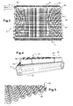
- the figure 2 is a schematic view of the heat exchanger 3 of the thermal management device 2 for conditioning the flow of air to the passenger compartment according to the invention.
- This heat exchanger 3 can be used in particular as an evaporator in an air conditioning loop 1 of a motor vehicle.
- the heat exchanger 3 allows a heat exchange between the refrigerant and the flow of air passing through the thermal management device 2.
- the refrigerant evaporating within the heat exchanger 3, working as an evaporator captures the heat energy of the flow of air to the passenger compartment, to allow the passage of refrigerant from a liquid phase to a gaseous phase.
- the external heat exchanger 5 (visible on the figure 1 ) is for example able to work as a condenser, the refrigerant then yielding heat energy to the outside air flow to allow the passage of refrigerant from the gas phase to a liquid phase.
- the heat exchanger 3 has a generally parallelepipedal general shape.
- the heat exchanger 3 comprises a heat exchange bundle 23.
- the heat exchange bundle 23 comprises in particular a successive stack of heat exchange tubes 25.
- a heat exchange tube 25 may comprise a first plate and a second plate assembled.
- a heat exchange tube 25 according to the embodiment of the figure 2 a general shape of rectangular parallelepiped.
- the heat exchange tubes 25 comprise respectively at least one coolant circulation channel.
- a coolant circulation channel may extend substantially over the entire length of a heat exchange tube 25 to obtain a large exchange surface.
- the heat exchange bundle 23 has at its longitudinal ends two closure plates 27, that is to say arranged on either side of the heat exchange tubes 25.
- the heat exchanger 3 may further comprise disturbing fins 29, each disposed between two adjacent heat exchange tubes 25, also between a heat exchange tube 25 and an adjacent closure plate 27.
- Disturbance fins 29 have the function of increasing the heat exchange surface between the refrigerant circulating in the heat exchange tubes 25 and the gas stream, such as the external air flow through the heat exchanger 3 .
- Such disturbing fins 29 may be formed from a metal strip, for example aluminum alloy.
- the heat exchange tubes 25 and the disturbance fins 29 may be brazed together.
- Disturbance vanes 29 may have a generally undulating shape.
- the disturbance fins 29 may be attached to the heat exchange tubes by their respective undulations, for example by brazing.
- At least one of the closure plates 27 has at least one orifice which opens into a so-called inlet or outlet pipe 31 for the supply or delivery of refrigerant fluid.
- the closure plates 27 comprises inlet and outlet pipes 31.
- the heat exchange tubes 25 are connected to each other in fluid communication via junction flanges 33 formed on the ends of the plates forming the heat exchange tubes 25.
- the junction flanges 33 may have come from material, preferably by stamping, so that they respectively form a projecting ring out of the plane of the plate and defining an opening for the passage of the coolant.
- the thermal management device 2 further comprises at least one thermal storage means 35 (shown schematically on the figure 1 and visible on the Figures 3 and 4 ).
- the thermal storage means 35 is particularly capable of capturing heat energy, for example to cool an air flow to the passenger compartment passing through the thermal storage means 35, in particular during a stop of the loop. air conditioning, and therefore a stop of the heat exchanger 3, here an evaporator 3.
- the thermal storage means 35 is arranged to be in direct contact with the flow of air to the passenger compartment. This makes it possible to efficiently exchange energy with the airflow to improve the comfort of the user in case of stopping the air conditioning loop.
- the thermal storage means 35 serves as a cooling device for the flow of air to the passenger compartment, annexed to the heat exchanger 3 for conditioning the flow of air to the passenger compartment working as an evaporator .
- the thermal storage means 35 is arranged downstream of the heat exchanger 3 for conditioning the flow of air to the passenger compartment, according to the direction of flow of the air flow to the passenger compartment.
- the thermal storage means 35 can be attached to the heat exchanger 3 for conditioning the flow of air to the passenger compartment.
- the thermal storage means 35 can also be arranged in the air conditioning unit 7.
- the cooling fluid cools the flow of air to the passenger compartment through the heat exchanger, the air flow to the cabin cooling in turn the means of Thermal storage 35.
- the thermal storage means 35 which cools the flow of air to the passenger compartment passing therethrough.
- the thermal storage means 35 comprises a composite phase change material 37 ensuring the storage of heat energy and the return thereof, when the air conditioning loop, and therefore the compressor 11 are stopped.
- the first phase-change material transfers heat energy to the airflow to the passenger compartment by passing into the solid phase.
- the air conditioning loop is stopped, the flow of air to the passenger compartment in contact with the phase change material is cooled by the latter which takes heat energy from it in the liquid phase. Also referred to as freeze / thaw phases of the first phase change material.
- the first phase change material used in the composite phase change material 37 is for example selected to have a phase change temperature in the range of 9 ° C to 13 ° C. This temperature range corresponding to the temperature range of the air flow coming from the heat exchanger 3 working in the evaporator when the air conditioning loop is operating, allows a better freezing of the first phase-change material and therefore an increase in the time of thermal comfort.
- a second criterion for selecting the first phase change material is the latent heat of phase change to ensure a large energy storage capacity.
- the first phase-change material used advantageously has a latent heat of between 100 and 300 kJ / kg.
- the first phase change material used in the material to composite phase change 37 may especially be a material with organic or inorganic phase change vegetable or other origin.
- the first phase change material may comprise paraffin.
- the second material or materials are selected to allow the composite phase change material 37 to maintain a solid support structure irrespective of the solid or liquid state of the first phase change material.
- the second material or materials are, for example, also chosen to provide a seal preventing leakage of the first phase change material into the liquid phase.
- a second material it is possible to provide, by way of example, a polymer and / or carbon fibers.
- the composite phase change material 37 can be made in the form of a matrix of polymer and carbon fibers allowing the composite phase change material 37 to be sufficiently solid in the solid phases or liquid of the first phase change material.
- the thermal storage means 35 further comprises at least one thermal conduction means 43 arranged in thermal contact with the composite phase-change material 37 and in order to exchange calories with the flow of heat. air to the passenger compartment, as shown schematically on the figure 5 .
- thermal contact means that thermal conduction is possible between the heat conduction means 43 and the composite phase change material 37.
- the heat conduction means 43 may in particular cool the composite phase change material. 37.
- the heat conduction means 43 is arranged in direct contact with the composite phase change material 37.
- the composite phase change material 37 is thus cooled by both convection and conduction.
- the thermal storage means 35 has a stack of composite phase change materials 37 between which are interposed thermal conduction means 43 called spacers.
- the composite phase change materials 37 are cooled by thermal conduction by the tabs 43 in contact with the composite phase change materials 37 and by the flow of air to the passenger compartment leaving the heat exchanger 3.
- the spacers 43 are advantageously made of a material with high thermal conduction power, for example metal material such as aluminum.
- it may be tabs 43 arranged between the composite phase change materials 37, as illustrated in FIG. figure 7 .
- the spacers 43 may be formed from a metal strip, for example aluminum alloy.
- the tabs 43 respectively have a shape creating disturbances of the flow of air flow to the passenger passing through them. These disturbances make it possible to increase the heat exchange with the flow of air to the passenger compartment. A better exchange with the flow of air to the passenger compartment allows a better efficiency of the freezing / thawing phases of the first phase change material.
- the spacers 43 may have a generally undulating or crenellated general shape as illustrated in FIG. 8.
- the corrugations or crenellations 45 of the spacers 43 are arranged directly in contact with a composite phase-change material.
- the corrugations or crenellations 45 of the spacers have a height of between 2 mm and 5 mm.
- the spacers 43 have rows of corrugations or crenellations 45.
- the corrugations or crenellations 45 from one row to the other are shifted in order to disrupt the flow of air and improve heat exchange.
- the assembly 37, 43 formed by the composite material (s) with phase change (s) and one or more spacers 43 may be mounted in a support 47 also allowing thermal conduction and fixed to the internal heat exchanger 3.
- the thermal storage means may comprise a metal frame 47, for example made of aluminum or aluminum alloy, forming a support for the stack of phase-change materials. composites 37 and tabs 43.
- the metal frame 47 has for example hooks 50 more visible on the figures 7 and 9. These hooks 50 are also made of a thermally conductive material, for example metal such as aluminum.
- the frame 47 forms a thermal conduction link between the heat exchanger 3 working in the evaporator and more precisely the heat exchange tubes 25 in which the refrigerant circulates, and the thermal storage means 35, and more precisely the material (s) (x) with a composite phase change (s) 37.
- the composite phase change material (s) 37 are further cooled by conduction through the frame 47 which is in contact with the heat exchange tubes 25 of the internal heat exchanger 3 working in evaporator mode.
- the thermal storage means 35 comprises at least one rim 49 covering at least one edge of the composite phase change materials 37. Said wafer being disposed opposite the heat exchanger 3. This rim 49 has the This function protects the phase change material contained in the composite phase change material 37. The latter is thus less likely to evaporate on contact with the second heat transfer fluid.
- the flange 49 may preferably be integral with at least one of the tabs 43 located in the thermal storage means 35. This then facilitates the mounting of said flange 49.
- the flange 49 can, according to a first embodiment presented to the figure 6 come from matter with the same interlayer.
- a slice of composite phase change material 37 may be covered by two flanges 49 crenellated and complementary arranged in a mutual interlocking. These flanges 49 come from materials with separate tabs 43 located on either side of the composite phase change material 37 within the stack. The said crenellated rims 49 being nested one in the other.
- This second embodiment makes it possible to produce only one type of complementary interleaves and thus makes it possible to save production costs.
- the spacers 43 may be of metal material, the formation of the corrugations or crenellations 45 and the flange 49 may be for example made in a single stamping step.
- An additional flange 49 may also be disposed on the edge of the composite phase change material 37 opposite that facing the heat exchanger 3 so as to cover it.
- This additional flange 49 may come from a spacer 43 already having a flange 49 coming to cover the edge of the composite phase change materials 37 vis-à-vis the heat exchanger 3.
- this additional flange 49 may come from a spacer 43 that does not already have a flange 49 coming to cover the edge of the composite phase change materials 37 vis-à-vis the heat exchanger 3. This also allows to produce only one type of interleaves and thus allows to save production.
- each insert 43 comprises rows of the slots 45, alternately offset with respect to each other, and distributed parallel to the flange 49.
- Each slot 45 extends projecting out of a base of the interlayer 43
- These tabs 43 are arranged in pairs facing each other so that the slots of one of the tabs 43 extend to the crenellations of the other of the tabs 43.
- thermal storage means 35 it is also possible for the thermal storage means 35 to have tabs 43 offset in pairs from one another so that the slots of one of the tabs 43 extend in line with the flat surfaces of the web. other tabs 43.
- thermal management device 2 avoids evaporation of the phase change material and thus allows it to retain these characteristics over time.
Landscapes
- Engineering & Computer Science (AREA)
- Physics & Mathematics (AREA)
- Thermal Sciences (AREA)
- Mechanical Engineering (AREA)
- General Engineering & Computer Science (AREA)
- Air-Conditioning For Vehicles (AREA)
- Heat-Exchange Devices With Radiators And Conduit Assemblies (AREA)
Abstract
- un échangeur thermique (3) au sein duquel circule un premier fluide caloporteur et destiné à être traversé par un second fluide caloporteur,
- au moins un moyen de stockage thermique (35) comprenant un empilement entre:
• une pluralité de matériaux à changement de phase composite (37), et
• des intercalaires (43) interposés entre les matériaux à changement de phase composites (37) et en contact thermique avec lesdits matériaux à changement de phase composite (37),
ledit empilement étant disposé perpendiculairement au flux du second fluide caloporteur en aval de l'échangeur thermique (3) selon le sens d'écoulement dudit flux du second fluide caloporteur,
ledit moyen de stockage thermique (35) comportant au moins un rebord (49) venant recouvrir au moins une tranche des matériaux à changement de phase composite (37), une telle tranche étant disposée en vis-à-vis dudit échangeur thermique (3).
Description
- L'invention concerne un dispositif de gestion thermique pour véhicule automobile et plus particulièrement un dispositif de gestion thermique comportant un matériau à changement de phase associé à un échangeur thermique.
- Un échangeur thermique a pour fonction d'assurer un échange thermique entre un premier fluide caloporteur en circulation à l'intérieur d'une pluralité de canaux, et un second fluide caloporteur extérieur, traversant l'échangeur thermique au sein d'un circuit de gestion thermique. Par exemple, dans le cas d'une boucle de climatisation, cette dernière comprend généralement au moins un échangeur thermique agencé en face avant aussi appelé échangeur thermique externe et un échangeur thermique agencé pour conditionner le flux d'air à destination de l'habitacle aussi nommé échangeur thermique interne.
- L'échangeur thermique externe permet un transfert thermique entre le premier fluide caloporteur qui est généralement un fluide réfrigérant et le second fluide caloporteur qui est l'air ambiant, tel qu'un flux d'air extérieur au véhicule.
- L'échangeur thermique interne permet un échange thermique entre le fluide réfrigérant et le flux d'air destiné à être délivré à l'intérieur de l'habitacle qui traverse l'échangeur thermique interne. Il s'agit généralement d'un évaporateur interne permettant de refroidir le flux d'air le traversant préalablement à sa distribution à l'intérieur de l'habitacle à travers une bouche de distribution d'air.
- Dans une boucle de climatisation permettant un refroidissement de l'air à destination de l'habitacle, l'échangeur thermique externe joue un rôle de condenseur et l'échangeur thermique interne joue un rôle d'évaporateur. Dans cette configuration, l'énergie calorifique prélevée par l'échangeur thermique interne au flux d'air à destination de l'habitacle est libérée par condensation du fluide réfrigérant au niveau de l'échangeur thermique externe.
- Toutefois, lorsque le moteur du véhicule est arrêté, la circulation du fluide réfrigérant n'a plus lieu, et l'échange thermique entre le flux d'air et le fluide réfrigérant ne peut s'opérer. L'air soufflé dans l'habitacle du véhicule n'est alors plus rafraîchi.
- Cette situation est d'autant plus problématique que des systèmes d'économie de carburant récents prévoient l'arrêt automatique du moteur lorsque la voiture s'immobilise, privant fréquemment l'habitacle d'air rafraîchi. Il s'agit notamment de véhicules automobiles équipés d'un alterno-démarreur pour la mise en oeuvre d'un dispositif d'arrêt et de redémarrage automatique du moteur, par exemple l'arrêt du moteur à un feu tricolore ou à un stop, entraîne l'arrêt du fonctionnement du compresseur de la boucle de climatisation et donc un arrêt du fonctionnement de cette dernière.
- Afin de remédier à l'arrêt du rafraîchissement de l'air soufflé dans l'habitacle lorsque le moteur est stoppé, il est connu d'utiliser dispositif de gestion thermique comportant un matériau à changement de phase associé à un échangeur thermique. Il est ainsi connu de placer un matériau à changement de phase composite, dans le flux du second fluide caloporteur en aval de l'échangeur thermique.
- Lorsque la boucle de climatisation fonctionne, le matériau à changement de phase cède de l'énergie calorifique au fluide réfrigérant en passant en phase solide. Lorsque la boucle de climatisation est à l'arrêt, le flux d'air à destination de l'habitacle circulant au contact du matériau à changement de phase est refroidi par ce dernier qui lui prélève de l'énergie calorifique en passant en phase liquide.
- Ainsi, lorsque le moteur du véhicule est en marche, le fluide réfrigérant refroidit à la fois l'air traversant l'échangeur thermique et le moyen de stockage thermique. Le moyen de stockage thermique capte quant à lui l'énergie calorifique de l'air traversant l'échangeur thermique afin de le refroidir lorsque le moteur est coupé.
- Néanmoins, dans le cas d'une boule de climatisation, le second fluide caloporteur est de l'air et le matériau à changement de phase compris dans le matériau à changement de phase composite peut subir une certaine évaporation ce qui avec le temps diminue l'efficacité du moyen de stockage thermique.
- Un des buts de la présente invention est de remédier au moins partiellement aux inconvénients de l'art antérieur et de proposer un échangeur thermique avec un moyen de stockage thermique amélioré.
- La présente invention concerne donc Dispositif de gestion thermique comportant :
- un échangeur thermique au sein duquel circule un premier fluide caloporteur et destiné à être traversé par un second fluide caloporteur,
- au moins un moyen de stockage thermique comprenant un empilement entre:
- une pluralité de matériaux à changement de phase composite, et
- des intercalaires interposés entre les matériaux à changement de phase composites et en contact thermique avec lesdits matériaux à changement de phase composite,
- Ce rebord a comme fonction la protection du matériau à changement de phase contenu dans le matériau à changement de phase composite. Ce dernier a ainsi moins de risques de s'évaporer au contact du second fluide caloporteur.
- Selon un aspect de l'invention, le rebord vient de matière avec au moins une des intercalaires du moyen de stockage thermique.
- Le fait que le rebord vienne de matière avec au moins une des intercalaires permet de le réaliser en même temps que ladite intercalaire et ainsi d'effectuer des économies de production.
- Selon un autre aspect de l'invention, le rebord recouvrant une tranche de matériau à changement de phase composite vient de matière avec un même intercalaire.
- Selon un autre aspect de l'invention, une tranche de matériau à changement de phase composite est recouverte par deux rebords crénelés et complémentaires agencés selon un emboitement mutuel, lesdits rebords venant de matières avec des intercalaires distinctes situées de part et d'autre du matériau à changement de phase composite.
- Selon un autre aspect de l'invention, les intercalaires sont réalisée en matière métallique et que leur mise en forme est réalisées par emboutissage.
- Selon un autre aspect de l'invention, chaque intercalaire comprend des rangées des créneaux répartis parallèlement au rebord, les rangées étant alternativement décalées l'une par rapport à l'autre.
- Selon un autre aspect de l'invention, le moyen de stockage thermique comporte des intercalaires disposés par paire en vis-à-vis l'un de l'autre de sorte que les créneaux de l'un des intercalaires s'étendent au droit des créneaux de l'autre des intercalaires.
- Selon un autre aspect de l'invention, le moyen de stockage thermique comporte des intercalaires décalés par paire l'un de l'autre de sorte que les créneaux de l'un des intercalaires s'étendent au droit de surfaces planes de l'autre des intercalaires.
- Selon un autre aspect de l'invention, chaque créneau s'étend en saillie hors d'une base de l'intercalaire reliée au rebord.
- Selon un autre aspect de l'invention, l'empilement comporte en outre un rebord recouvrant la tranche des matériaux à changement de phase composite opposée à celle en vis-à-vis de l'échangeur thermique.
- La présente invention concerne également une boucle de climatisation comportant un dispositif de gestion thermique comme décrit précédemment.
- D'autres caractéristiques et avantages de l'invention apparaîtront plus clairement à la lecture de la description suivante, donnée à titre d'exemple illustratif et non limitatif, et des dessins annexés parmi lesquels :
- la
figure 1 montre une représentation schématique d'une boucle de climatisation, - la
figure 2 montre une représentation schématique en perspective d'un échangeur thermique, - la
figure 3 montre une représentation schématique en vue de face d'un dispositif de gestion, - la
figure 4 montre une représentation schématique en vue de côté du dispositif de gestion de lafigure 1 , - la
figure 5 montre une représentation schématique en perspective d'intercalaires, - la
figure 6 montre une représentation schématique en perspective d'une portion d'un moyen de stockage thermique selon un premier mode de réalisation, - la
figure 7 montre une représentation schématique en perspective d'une portion d'un moyen de stockage thermique selon un second mode de réalisation, - Sur ces figures, les éléments sensiblement identiques portent les mêmes références.
- L'invention concerne un dispositif de gestion thermique 2 comportant un échangeur thermique 3 dans lequel circule un premier fluide caloporteur, et traversé par un second fluide caloporteur ainsi qu'au moins un moyen de stockage thermique 35. Un tel dispositif de gestion thermique 2, est apte à être utilisé notamment dans une boucle de climatisation pour véhicule automobile comme illustré à la
figure 1 . Le premier fluide caloporteur peut alors être un fluide réfrigérant et le second fluide caloporteur un flux d'air par exemple destiné à l'habitacle dans le cas ou l'échangeur thermique 3 est un évaporateur. - La boucle de climatisation 1 comporte un dispositif de gestion thermique 2 destiné à conditionner un flux d'air à destination de l'habitacle du véhicule automobile, par échange thermique avec le fluide réfrigérant. Le dispositif de gestion thermique 2 est par exemple placé à l'intérieur d'un boîtier de climatisation 7. Le boîtier de climatisation 7 est situé généralement dans l'habitacle du véhicule.
- La boucle de climatisation 1 comporte en outre un échangeur thermique dit externe 5 destiné à être placé au contact de l'air extérieur du véhicule, par exemple au niveau de la face avant du véhicule automobile. L'échangeur thermique externe 5 peut être notamment couplé avec un ventilateur 9 qui permet le passage de l'air extérieur au travers de l'échangeur thermique externe 5, par exemple en cas de faible vitesse ou d'arrêt du véhicule automobile.
- Le fluide réfrigérant est mis en circulation par un compresseur 11 dont la fonction est d'augmenter la pression et la température du fluide réfrigérant. Le compresseur 11 est selon l'exemple illustré sur la
figure 1 placé amont de l'échangeur thermique externe 5 et en aval du dispositif de gestion thermique 2 selon le sens de circulation du fluide réfrigérant. - Bien entendu, on peut prévoir au moins un organe de détente (non représenté) permettant d'abaisser la pression du fluide réfrigérant avant évaporation.
- La boucle de climatisation 1 peut comprendre en outre un groupe moto-ventilateur 13 (schématisé sur la
figure 1 ) permettant de propulser le flux d'air à destination de l'habitacle à travers le boîtier de climatisation 7. Le flux d'air à destination de l'habitacle peut notamment être régulé par un ou plusieurs organes de mixage, tel que des volets de mixage 15. - Le flux d'air à destination de l'habitacle est distribué à des zones de l'habitacle via des conduits de distributions d'air 17, 19 et 21, reliées par exemple à des sorties d'air sous pare-brise, des sorties en façade du tableau de bord, ou encore des sorties d'air sous le tableau de bord en direction des pieds.
- La
figure 2 est une vue schématique de l'échangeur thermique 3 du dispositif de gestion thermique 2 destiné à conditionner le flux d'air à destination de l'habitacle selon l'invention. Cet échangeur thermique 3 peut être notamment utilisé en tant qu'évaporateur dans une boucle de climatisation 1 d'un véhicule automobile. - En fonctionnement, l'échangeur thermique 3 permet un échange thermique entre le fluide réfrigérant et le flux d'air traversant le dispositif de gestion thermique 2.
- Lorsque la boucle de climatisation 1 fonctionne de façon à refroidir le flux d'air à destination de l'habitacle, le fluide réfrigérant s'évaporant au sein de l'échangeur thermique 3, travaillant en évaporateur, capte de l'énergie calorique du flux d'air à destination de l'habitacle, afin de permettre le passage du fluide réfrigérant d'une phase liquide à une phase gazeuse. Dans ce mode de climatisation, l'échangeur thermique externe 5 (visible sur la
figure 1 ) est par exemple apte à travailler en condenseur, le fluide réfrigérant cédant alors de l'énergie calorifique au flux d'air extérieur afin de permettre le passage du fluide réfrigérant de la phase gazeuse à une phase liquide. - Selon l'exemple illustré sur la
figure 2 , l'échangeur thermique 3 présente une forme générale sensiblement parallélépipédique. - L'échangeur thermique 3 comprend un faisceau d'échange thermique 23.
- Le faisceau d'échange thermique 23 comprend notamment un empilement successif de tubes d'échange thermique 25. Selon un exemple de réalisation, un tube d'échange thermique 25 peut comprendre une première plaque et une deuxième plaque assemblées. Un tube d'échange thermique 25 présente selon l'exemple de réalisation de la
figure 2 une forme générale de parallélépipède rectangle. Les tubes d'échange thermique 25 comprennent respectivement au moins un canal de circulation du fluide réfrigérant. Un canal de circulation du fluide réfrigérant peut s'étendre sensiblement sur la totalité de la longueur d'un tube d'échange thermique 25 pour obtenir une surface d'échange importante. - En outre selon le mode de réalisation illustré, le faisceau d'échange thermique 23 présente à ses extrémités longitudinales deux plaques de fermeture 27, c'est-à-dire agencées de part et d'autre des tubes d'échange thermique 25.
- L'échangeur thermique 3 peut comprendre en outre des ailettes de perturbation 29, disposées à chaque fois entre deux tubes d'échange thermique 25 adjacents, également entre un tube d'échange thermique 25 et une plaque de fermeture 27 adjacente.
- Les ailettes de perturbation 29 ont pour fonction d'augmenter la surface d'échange thermique entre le fluide réfrigérant circulant dans les tubes d'échange thermique 25 et le flux gazeux, tel que le flux d'air extérieur qui traverse l'échangeur thermique 3.
- De telles ailettes de perturbation 29 peuvent être formées à partir d'un feuillard métallique, par exemple en alliage d'aluminium.
- Les tubes d'échange thermique 25 et les ailettes de perturbation 29 peuvent être brasées ensemble. Les ailettes de perturbation 29 peuvent présenter une forme générale sensiblement ondulée. Dans ce cas, les ailettes de perturbation 29 peuvent être fixées aux tubes d'échange thermique par leurs ondulations respectives, par exemple par brasage.
- De plus, au moins l'une des plaques de fermeture 27 présente au moins un orifice qui débouche dans une tubulure 31 dite d'entrée ou de sortie pour l'alimentation ou le refoulement en fluide réfrigérant. Sur la
figure 1 , seule l'une des plaques de fermeture 27 comprend des tubulures 31 d'entrée et de sortie. - Les tubes d'échange thermique 25 sont reliés les uns aux autres en communication de fluide par l'intermédiaire de brides de jonction 33 ménagées sur les extrémités des plaques formant les tubes d'échange thermique 25. Les brides de jonction 33 peuvent être venues de matière, de préférence par emboutissage, de sorte qu'elles forment respectivement un anneau faisant saillie hors du plan de la plaque et délimitant une ouverture pour le passage du fluide réfrigérant.
- Le dispositif de gestion thermique 2 comporte en outre, au moins un moyen de stockage thermique 35 (schématisé sur la
figure 1 et visible sur lesfigures 3 et 4 ). Le moyen de stockage thermique 35 est en particulier capable de capter de l'énergie calorifique par exemple afin de refroidir un flux d'air à destination de l'habitacle traversant le moyen de stockage thermique 35, notamment lors d'un arrêt de la boucle de climatisation, et donc d'un arrêt de l'échangeur thermique 3, ici un évaporateur 3. - À cet effet, le moyen de stockage thermique 35 est agencé de manière à être en contact direct avec le flux d'air à destination de l'habitacle. Ceci permet d'échanger efficacement de l'énergie avec le flux d'air pour améliorer le confort de l'utilisateur en cas d'arrêt de la boucle de climatisation.
- Le moyen de stockage thermique 35 fait office d'un dispositif de refroidissement du flux d'air à destination de l'habitacle, annexe à l'échangeur thermique 3 destiné à conditionner le flux d'air à destination de l'habitacle travaillant en évaporateur.
- Le moyen de stockage thermique 35 est agencé en aval de l'échangeur thermique 3 destiné à conditionner le flux d'air à destination de l'habitacle, selon le sens d'écoulement du flux d'air à destination de l'habitacle. En particulier, le moyen de stockage thermique 35 peut être fixé à l'échangeur thermique 3 destiné à conditionner le flux d'air à destination de l'habitacle.
- En conséquence, le moyen de stockage thermique 35 peut également être agencé dans le boîtier de climatisation 7.
- Ainsi, lorsque le moteur du véhicule est en marche, le fluide réfrigérant refroidit le flux d'air à destination de l'habitacle traversant l'échangeur thermique, le flux d'air à destination de l'habitacle refroidissant à son tour le moyen de stockage thermique 35. Lorsque le moteur est coupé, c'est le moyen de stockage thermique 35 qui refroidit le flux d'air à destination de l'habitacle le traversant.
- Selon l'invention, le moyen de stockage thermique 35 comprend un matériau à changement de phase composite 37 assurant le stockage d'énergie calorifique et la restitution de celle-ci, lorsque la boucle de climatisation, et donc le compresseur 11 sont à l'arrêt.
- Le matériau à changement de phase composite 37 comporte :
- au moins un premier matériau qui est un matériau à changement de phase, connu sous le sigle PCM pour l'anglais « Phase Change Material », et
- au moins un deuxième matériau, choisi(s) de manière à former une matrice de support du premier matériau à changement de phase.
- Lorsque la boucle de climatisation fonctionne, le premier matériau à changement de phase cède de l'énergie calorifique au flux d'air à destination de l'habitacle en passant en phase solide. Lorsque la boucle de climatisation est à l'arrêt, le flux d'air à destination de l'habitacle circulant au contact du matériau à changement de phase est refroidi par ce dernier qui lui prélève de l'énergie calorifique en passant en phase liquide. On parle également de phases de congélation / décongélation du premier matériau à changement de phase.
- Le premier matériau à changement de phase utilisé dans le matériau à changement de phase composite 37 est par exemple sélectionné pour avoir une température de changement de phase de l'ordre comprise entre 9 °C et 13°C. Cette plage de température correspondant à la plage de température du flux d'air provenant de l'échangeur thermique 3 travaillant en évaporateur lorsque la boucle de climatisation fonctionne, permet une meilleure congélation du premier matériau à changement de phase et donc une augmentation du temps de confort thermique.
- Un deuxième critère de sélection du premier matériau à changement de phase est la chaleur latente de changement de phase pour garantir une grande capacité de stockage d'énergie. Selon le mode de réalisation décrit, le premier matériau à changement de phase utilisé présente avantageusement une chaleur latente comprise entre 100 et 300 kJ/kg.
- Le premier matériau à changement de phase utilisé dans le matériau à changement de phase composite 37 peut notamment être un matériau à changement de phase organique ou inorganique végétale ou d'autre origine. À titre d'exemple, le premier matériau à changement de phase peut comporter de la paraffine.
- Le ou les deuxièmes matériaux sont choisis de façon à permettre au matériau à changement de phase composite 37 de conserver une structure de support solide quel que soit l'état solide ou liquide du premier matériau à changement de phase.
- Le ou les deuxièmes matériaux sont par exemple également choisis pour assurer une étanchéité empêchant une fuite du premier matériau à changement de phase dans la phase liquide.
- En deuxième matériau, on peut prévoir à titre d'exemple un polymère et/ou des fibres de carbone.
- Ainsi, selon un exemple particulier, le matériau à changement de phase composite 37 peut être réalisé sous la forme d'une matrice de polymère et de fibres de carbone permettant au matériau à changement de phase composite 37 d'être suffisamment solide dans les phases solide ou liquide du premier matériau à changement de phase.
- Afin d'améliorer les échanges thermiques, le moyen de stockage thermique 35 comporte en outre au moins un moyen de conduction thermique 43 agencé en contact thermique avec le matériau à changement de phase composite 37 et de manière à échanger des calories avec le flux d'air à destination de l'habitacle, comme schématisé sur la
figure 5 . - On entend par « contact thermique », le fait qu'une conduction thermique est possible entre le moyen de conduction thermique 43 et le matériau à changement de phase composite 37. Le moyen de conduction thermique 43 peut notamment refroidir le matériau à changement de phase composite 37.
- Plus précisément, le moyen de conduction thermique 43 est agencé en contact direct avec le matériau à changement de phase composite 37.
- Lorsque la boucle de climatisation fonctionne, le moyen de conduction thermique 43 est refroidi par convection par le flux d'air refroidi par passage dans l'échangeur thermique interne 3 travaillant en évaporateur. Le matériau à changement de phase composite 37 est refroidi par:
- convection par le flux d'air à destination de l'habitacle en sortie de l'échangeur thermique interne 3 travaillant en évaporateur, grâce au contact direct entre le flux d'air à destination de l'habitacle et le matériau à changement de phase composite 37, et également
- par conduction par le moyen de conduction thermique 43 refroidi par le flux d'air à destination de l'habitacle par convection, du fait que le moyen de conduction thermique 43 soit agencé en contact direct avec le matériau à changement de phase composite 37.
- Le matériau à changement de phase composite 37 est donc refroidi à la fois par convection et conduction.
- Lorsque la boucle de climatisation est à l'arrêt, le flux d'air à destination de l'habitacle traversant le moyen de stockage thermique 35 est refroidi par convection par le matériau à changement de phase composite 37 comme expliqué précédemment et en outre par le moyen de conduction thermique 43.
- Selon un mode de réalisation illustré sur les
figures 5 et6 , le moyen de stockage thermique 35 présente un empilement de matériaux à changement de phase composite 37 entre lesquels sont intercalés des moyens de conduction thermique 43 appelés intercalaires. - Ainsi, lorsque la boucle de climatisation fonctionne, les matériaux à changement de phase composite 37 sont refroidis par conduction thermique par les intercalaires 43 en contact avec les matériaux à changement de phase composite 37 et par le flux d'air à destination de l'habitacle sortant de l'échangeur thermique 3.
- Lorsque la boucle de climatisation est à l'arrêt, le flux d'air à destination de l'habitacle est refroidi par convection grâce à la transition de phase du premier matériau à changement de phase utilisé dans les matériaux à changement de phase composites 37, comme expliqué précédemment, et grâce aux intercalaires 43 qui améliorent donc les échanges thermiques avec le flux d'air à destination de l'habitacle.
- Les intercalaires 43 sont avantageusement réalisés en un matériau à fort pouvoir de conduction thermique, par exemple en matériau métallique comme l'aluminium.
- En particulier, il peut s'agir d'intercalaires 43 agencés entre les matériaux à changement de phase composite 37, tel qu'illustré sur la
figure 7 . - Les intercalaires 43 peuvent être formés à partir d'un feuillard métallique, par exemple en alliage d'aluminium.
- Avantageusement, les intercalaires 43 présentent respectivement une forme créant des perturbations de l'écoulement du flux d'air à destination de l'habitacle passant à travers eux. Ces perturbations permettent d'augmenter l'échange thermique avec le flux d'air à destination de l'habitacle. Un meilleur échange avec le flux d'air à destination de l'habitacle permet une meilleure efficacité des phases de congélation / décongélation du premier matériau à changement de phase.
- Les intercalaires 43 peuvent présenter une forme générale sensiblement ondulée ou crénelée comme illustré à la figure 8. Les ondulations ou créneaux 45 des intercalaires 43 sont agencées directement en contact avec un matériau à changement de phase composite. Les ondulations ou créneaux 45 des intercalaires présentent par exemple une hauteur comprise entre 2mm et 5mm.
- Les intercalaires 43 présentent des rangées d'ondulations ou créneaux 45. Les ondulations ou créneaux 45 d'une rangée à l'autre sont décalées afin de perturber le flux d'air et améliorer les échanges thermiques.
- L'ensemble 37, 43 formé par le(s) matériau(x) à changement de phase composite(s) et une ou plusieurs intercalaires 43 peut être monté dans un support 47 permettant également une conduction thermique et fixé à l'échangeur thermique interne 3.
- À titre d'exemple, le moyen de stockage 35 thermique peut comporter un cadre métallique 47, par exemple en aluminium ou en alliage d'aluminium, formant support de l'empilement de matériaux à changement de phase composites 37 et d'intercalaires 43.
- Le cadre métallique 47 présente par exemple des accroches 50 mieux visibles sur les
figures 7 et 9. Ces accroches 50 sont également en un matériau conducteur thermique, par exemple métalliques tel qu'en aluminium. - Ceci permet d'ajouter une conduction thermique entre la source froide formée par l'échangeur thermique 3 travaillant en évaporateur et le ou les matériaux à changement de phase composites 37 du moyen de stockage thermique 35.
- Le cadre 47 forme un lien de conduction thermique entre l'échangeur thermique 3 travaillant en évaporateur et plus précisément les tubes d'échange thermique 25 dans lesquels circule le réfrigérant, et le moyen de stockage thermique 35, et plus précisément le(s) matériau(x) à changement de phase composite(s) 37. On obtient ainsi une conduction thermique des calories, ici des frigories des tubes d'échange thermique 25, vers le ou les matériaux à changement de phase composites 37 du moyen de stockage thermique 35, favorisant ainsi une congélation rapide et donc une meilleure efficacité de stockage du premier matériau à changement de phase utilisé dans le matériau à changement de phase composite 37.
- Ainsi, lorsque la boucle de climatisation fonctionne, le ou les matériaux à changement de phase composites 37 sont en outre refroidis par conduction par l'intermédiaire du cadre 47 qui est en contact avec les tubes d'échanges thermiques 25 de l'échangeur interne 3 travaillant en mode évaporateur.
- Comme montré sur les
figures 6 et 7 , le moyen de stockage thermique 35 comporte au moins un rebord 49 venant recouvrir au moins une tranche des matériaux à changement de phase composite 37. Ladite tranche étant disposée en vis-à-vis de l'échangeur thermique 3. Ce rebord 49 a comme fonction la protection du matériau à changement de phase contenu dans le matériau à changement de phase composite 37. Ce dernier a ainsi moins de risques de s'évaporer au contact du second fluide caloporteur. - Le rebord 49 peut de préférence venir de matière avec au moins une des intercalaires 43 situées du moyen de stockage thermique 35. Cela facilite alors le montage dudit rebord 49. Le rebord 49 peut, selon un premier mode de réalisation présenté à la
figure 6 , venir de matière avec un même intercalaire. - Selon un second mode de réalisation illustré à la
figure 7 , une tranche de matériau à changement de phase composite 37 peut être recouverte par deux rebords 49 crénelés et complémentaires agencés selon un emboitement mutuel. Lesdits rebords 49 viennent de matières avec des intercalaires 43 distincts situés de part et d'autre du matériau à changement de phase composite 37 au sein de l'empilement. Lesdits rebords 49 crénelés étant emboités les un dans les autres. Ce second mode de réalisation permet de ne produire qu'un seul type d'intercalaires complémentaires et ainsi permet de réaliser des économies de productions. - Les intercalaires 43 pouvant être en matière métallique, la formation des ondulations ou créneaux 45 ainsi que du rebord 49 peut être par exemple réalisée en une seule étape d'emboutissage.
- Un rebord 49 supplémentaire peut également être disposé sur la tranche des matériaux à changement de phase composite 37 opposée à celle en vis-à-vis de l'échangeur thermique 3 de sorte à la recouvrir. Ce rebord 49 supplémentaire peut venir d'un intercalaire 43 comportant déjà un rebord 49 venant recouvrir la tranche des matériaux à changement de phase composite 37 en vis-à-vis de l'échangeur thermique 3.
- A contrario, ce rebord 49 supplémentaire peut venir d'un intercalaire 43 ne comportant pas déjà un rebord 49 venant recouvrir la tranche des matériaux à changement de phase composite 37 en vis-à-vis de l'échangeur thermique 3. Cela permet ainsi également de ne produire qu'un seul type d'intercalaires et ainsi permet de réaliser des économies de productions.
- Ainsi, chaque intercalaire 43 comprend des rangées des créneaux 45, alternativement décalées l'une par rapport à l'autre, et répartis parallèlement au rebord 49. Chaque créneau 45 s'étend en saillie hors d'une base de l'intercalaire 43 reliée au rebord 49. Ces intercalaires 43 sont disposés par paire en vis-à-vis l'un de l'autre de sorte que les créneaux de l'un des intercalaires 43 s'étendent au droit des créneaux de l'autre des intercalaires 43.
- A contrario, il est également possible que le moyen de stockage thermique 35 comporte des intercalaires 43 décalés par paire l'un de l'autre de sorte que les créneaux de l'un des intercalaires 43 s'étendent au droit de surfaces planes de l'autre des intercalaires 43.
- Ainsi, on voit bien que le dispositif de gestion thermique 2 selon l'invention permet d'éviter une évaporation du matériau à changement de phase et ainsi lui permet de conserver ces caractéristiques dans le temps.
ledit moyen de stockage thermique comportant au moins un rebord venant recouvrir au moins une tranche des matériaux à changement de phase composite, ladite tranche étant disposée en vis-à-vis dudit échangeur thermique.
Claims (11)
- Dispositif de gestion thermique (2) comportant :- un échangeur thermique (3) au sein duquel circule un premier fluide caloporteur et destiné à être traversé par un second fluide caloporteur,- au moins un moyen de stockage thermique (35) comprenant un empilement entre:ledit empilement étant disposé perpendiculairement au flux du second fluide caloporteur en aval de l'échangeur thermique (3) selon le sens d'écoulement dudit flux du second fluide caloporteur,• une pluralité de matériaux à changement de phase composites (37), et• des intercalaires (43) interposés entre les matériaux à changement de phase composites (37) et en contact thermique avec lesdits matériaux à changement de phase composite (37),
caractérisé en ce que ledit moyen de stockage thermique (35) comporte au moins un rebord (49) venant recouvrir au moins une tranche d'au moins un des matériaux à changement de phase composites (37), une telle tranche étant disposée en vis-à-vis dudit échangeur thermique (3). - Dispositif de gestion thermique (2) selon la revendication précédente, caractérisé en ce que le rebord (49) vient de matière avec au moins un des intercalaires (43) dudit moyen de stockage thermique (35).
- Dispositif de gestion thermique (2) selon la revendication 2, caractérisé en ce que le rebord (49) recouvrant la tranche de matériau à changement de phase composite (37) vient de matière avec un même intercalaire (43).
- Dispositif de gestion thermique (2) selon la revendication 2, caractérisé en ce que la tranche de matériau à changement de phase composite (37) est recouverte par deux rebords (49) crénelés et complémentaires agencés selon un emboîtement mutuel, lesdits rebords (49) venant de matière avec des intercalaires (43) distincts situés de part et d'autre du matériau à changement de phase composite (37).
- Dispositif de gestion thermique (2) selon l'une des revendications 2 à 4, caractérisé en ce que les intercalaires (43) sont réalisés en matière métallique et que leur mise en forme est réalisée par emboutissage.
- Dispositif de gestion thermique (2) selon l'une des revendications 2 à 5, caractérisé en ce que chaque intercalaire (43) comprend des rangées des créneaux (45) répartis parallèlement au rebord (49), les rangées étant alternativement décalées l'une par rapport à l'autre.
- Dispositif de gestion thermique (2) selon la revendication précédente, caractérisé en ce que le moyen de stockage thermique (35) comporte des intercalaires (43) disposés par paire en vis-à-vis l'un de l'autre de sorte que les créneaux de l'un des intercalaires (43) s'étendent au droit des créneaux de l'autre des intercalaires (43).
- Dispositif de gestion thermique (2) selon la revendication 6, caractérisé en ce que le moyen de stockage thermique (35) comporte des intercalaires (43) décalés par paire l'un de l'autre de sorte que les créneaux de l'un des intercalaires (43) s'étendent au droit de surfaces planes de l'autre des intercalaires (43).
- Dispositif de gestion thermique (2) selon l'une quelconque des revendications 6 à 8, caractérisé en ce que chaque créneau (45) s'étend en saillie hors d'une base de l'intercalaire (43) reliée au rebord (49).
- Dispositif de gestion thermique (2) selon l'une des revendications précédentes, caractérisé en ce que l'empilement comporte en outre un rebord (49) recouvrant la tranche des matériaux à changement de phase composite (37) opposée à celle en vis-à-vis de l'échangeur thermique (3).
- Boucle de climatisation (1) caractérisée en ce qu'elle comporte un dispositif de gestion thermique (2) selon l'une des revendications précédentes.
Applications Claiming Priority (1)
| Application Number | Priority Date | Filing Date | Title |
|---|---|---|---|
| FR1458385A FR3025595B1 (fr) | 2014-09-08 | 2014-09-08 | Dispositif de gestion thermique a materiau a changement de phase pour vehicule automobile |
Publications (2)
| Publication Number | Publication Date |
|---|---|
| EP2993436A1 true EP2993436A1 (fr) | 2016-03-09 |
| EP2993436B1 EP2993436B1 (fr) | 2019-07-31 |
Family
ID=52007071
Family Applications (1)
| Application Number | Title | Priority Date | Filing Date |
|---|---|---|---|
| EP15184354.7A Active EP2993436B1 (fr) | 2014-09-08 | 2015-09-08 | Dispositif de gestion thermique à matériau à changement de phase pour véhicule automobile |
Country Status (3)
| Country | Link |
|---|---|
| EP (1) | EP2993436B1 (fr) |
| JP (1) | JP6643015B2 (fr) |
| FR (1) | FR3025595B1 (fr) |
Cited By (1)
| Publication number | Priority date | Publication date | Assignee | Title |
|---|---|---|---|---|
| FR3060863A1 (fr) * | 2016-12-15 | 2018-06-22 | Valeo Systemes Thermiques | Gestion de temperature de batterie |
Citations (4)
| Publication number | Priority date | Publication date | Assignee | Title |
|---|---|---|---|---|
| DE102004035818A1 (de) * | 2004-07-23 | 2006-03-16 | Valeo Klimasysteme Gmbh | Wärmetauscher mit Latentspeicher |
| JP2011133182A (ja) * | 2009-12-25 | 2011-07-07 | Showa Denko Kk | 蓄冷機能付きエバポレータ |
| EP2653329A1 (fr) * | 2012-04-20 | 2013-10-23 | Delphi Technologies, Inc. | Evaporateur avec matériau à changement de phase pour mode d'opération comme thermosiphon |
| EP2875976A1 (fr) * | 2013-11-12 | 2015-05-27 | Valeo Systemes Thermiques | Dispositif de conditionnement thermique d'un flux d'air notamment pour véhicule automobile |
Family Cites Families (7)
| Publication number | Priority date | Publication date | Assignee | Title |
|---|---|---|---|---|
| AU2003223946A1 (en) * | 2002-03-09 | 2003-09-22 | Behr Gmbh And Co. | Heat exchanger |
| JP2010139201A (ja) * | 2008-12-15 | 2010-06-24 | Showa Denko Kk | 蓄冷器およびこれを用いた車両用空調装置 |
| EP2518126B1 (fr) * | 2009-12-25 | 2019-03-20 | JSR Corporation | Composition pour matériau de stockage de chaleur, et matériau de stockage de chaleur |
| JP2013241499A (ja) * | 2012-05-18 | 2013-12-05 | Kuraray Co Ltd | 蓄熱材用組成物及び蓄熱材 |
| JP2014073781A (ja) * | 2012-10-05 | 2014-04-24 | Calsonic Kansei Corp | 蓄冷熱交換器 |
| JP6126361B2 (ja) * | 2012-11-26 | 2017-05-10 | 株式会社日本クライメイトシステムズ | 蓄冷機能付き空気冷却器 |
| JP2014145571A (ja) * | 2013-01-30 | 2014-08-14 | Denso Corp | 排気熱交換器 |
-
2014
- 2014-09-08 FR FR1458385A patent/FR3025595B1/fr not_active Expired - Fee Related
-
2015
- 2015-09-07 JP JP2015175877A patent/JP6643015B2/ja active Active
- 2015-09-08 EP EP15184354.7A patent/EP2993436B1/fr active Active
Patent Citations (4)
| Publication number | Priority date | Publication date | Assignee | Title |
|---|---|---|---|---|
| DE102004035818A1 (de) * | 2004-07-23 | 2006-03-16 | Valeo Klimasysteme Gmbh | Wärmetauscher mit Latentspeicher |
| JP2011133182A (ja) * | 2009-12-25 | 2011-07-07 | Showa Denko Kk | 蓄冷機能付きエバポレータ |
| EP2653329A1 (fr) * | 2012-04-20 | 2013-10-23 | Delphi Technologies, Inc. | Evaporateur avec matériau à changement de phase pour mode d'opération comme thermosiphon |
| EP2875976A1 (fr) * | 2013-11-12 | 2015-05-27 | Valeo Systemes Thermiques | Dispositif de conditionnement thermique d'un flux d'air notamment pour véhicule automobile |
Cited By (1)
| Publication number | Priority date | Publication date | Assignee | Title |
|---|---|---|---|---|
| FR3060863A1 (fr) * | 2016-12-15 | 2018-06-22 | Valeo Systemes Thermiques | Gestion de temperature de batterie |
Also Published As
| Publication number | Publication date |
|---|---|
| FR3025595B1 (fr) | 2016-09-30 |
| EP2993436B1 (fr) | 2019-07-31 |
| FR3025595A1 (fr) | 2016-03-11 |
| JP6643015B2 (ja) | 2020-02-12 |
| JP2016057058A (ja) | 2016-04-21 |
Similar Documents
| Publication | Publication Date | Title |
|---|---|---|
| FR3074272B1 (fr) | Circuit de gestion thermique d'un vehicule hybride ou electrique | |
| FR3056290B1 (fr) | Dispositif de regulation thermique | |
| FR3007514A1 (fr) | Tube a reservoir de materiau a changement de phases pour faisceau d'echange de chaleur, notamment pour un evaporateur d'un circuit de climatisation d'un vehicule | |
| FR3025873A1 (fr) | Evaporateur stockeur avec design plaques gaufrettes facilitant la congelation du pcm | |
| EP2875976A1 (fr) | Dispositif de conditionnement thermique d'un flux d'air notamment pour véhicule automobile | |
| FR3033946B1 (fr) | Batterie thermique, notamment pour vehicule automobile, et utilisation correspondante | |
| EP2993436B1 (fr) | Dispositif de gestion thermique à matériau à changement de phase pour véhicule automobile | |
| EP2809535B1 (fr) | Ensemble comprenant un échangeur de chaleur et un support sur lequel ledit échangeur est monté | |
| EP3002538B1 (fr) | Echangeur de chaleur, notamment pour véhicule automobile | |
| FR3099642A1 (fr) | Dispositif de régulation thermique d’au moins un pack de batteries électriques de véhicules automobile | |
| EP2912397A1 (fr) | Boite collectrice pour échangeur de chaleur, notamment refroidisseur d'air de suralimentation de moteur de véhicule automobile | |
| FR3026477A1 (fr) | Echangeur thermique a degivrage ameliore | |
| FR3066811A1 (fr) | Ailette pour echangeur de chaleur avec bande d'attaque inclinee | |
| FR3099236A1 (fr) | Échangeur thermique pour installation de refroidissement et/ou chauffage et/ou ventilation et/ou climatisation | |
| FR3026474B1 (fr) | Dispositif de stockage thermique, module d'echange d'energie thermique et installation de climatisation comprenant ledit dispositif | |
| FR3052109A1 (fr) | Module d’echange thermique, face avant et vehicule automobile correspondants | |
| EP3732379A1 (fr) | Dispositif de ventilation pour vehicule automobile | |
| WO2023180030A1 (fr) | Dispositif de regulation thermique d'un organe de stockage d'energie electrique | |
| FR3067399A1 (fr) | Systeme de ventilation pour vehicule automobile | |
| FR3112720A1 (fr) | Module de refroidissement pour véhicule automobile électrique ou hybride | |
| FR3126760A1 (fr) | Echangeur de chaleur d’une boucle de fluide refrigerant. | |
| FR3099235A1 (fr) | Échangeur thermique pour installation de refroidissement et/ou chauffage et/ou ventilation et/ou climatisation | |
| FR3088710A1 (fr) | Echangeur de chaleur pour vehicule automobile | |
| FR3077334A1 (fr) | Dispositif de ventilation pour vehicule automobile | |
| FR3052299A1 (fr) | Systeme de generation d'energie pour vehicule comprenant une pile a combustible a refroidissement liquide et les echangeurs thermiques associes, vehicule correspondant. |
Legal Events
| Date | Code | Title | Description |
|---|---|---|---|
| PUAI | Public reference made under article 153(3) epc to a published international application that has entered the european phase |
Free format text: ORIGINAL CODE: 0009012 |
|
| AK | Designated contracting states |
Kind code of ref document: A1 Designated state(s): AL AT BE BG CH CY CZ DE DK EE ES FI FR GB GR HR HU IE IS IT LI LT LU LV MC MK MT NL NO PL PT RO RS SE SI SK SM TR |
|
| AX | Request for extension of the european patent |
Extension state: BA ME |
|
| 17P | Request for examination filed |
Effective date: 20160901 |
|
| RBV | Designated contracting states (corrected) |
Designated state(s): AL AT BE BG CH CY CZ DE DK EE ES FI FR GB GR HR HU IE IS IT LI LT LU LV MC MK MT NL NO PL PT RO RS SE SI SK SM TR |
|
| GRAP | Despatch of communication of intention to grant a patent |
Free format text: ORIGINAL CODE: EPIDOSNIGR1 |
|
| STAA | Information on the status of an ep patent application or granted ep patent |
Free format text: STATUS: GRANT OF PATENT IS INTENDED |
|
| RIC1 | Information provided on ipc code assigned before grant |
Ipc: F28D 1/03 20060101AFI20190211BHEP Ipc: F28F 3/02 20060101ALN20190211BHEP Ipc: B60H 1/00 20060101ALI20190211BHEP Ipc: F28D 20/02 20060101ALI20190211BHEP |
|
| INTG | Intention to grant announced |
Effective date: 20190312 |
|
| GRAS | Grant fee paid |
Free format text: ORIGINAL CODE: EPIDOSNIGR3 |
|
| GRAA | (expected) grant |
Free format text: ORIGINAL CODE: 0009210 |
|
| STAA | Information on the status of an ep patent application or granted ep patent |
Free format text: STATUS: THE PATENT HAS BEEN GRANTED |
|
| AK | Designated contracting states |
Kind code of ref document: B1 Designated state(s): AL AT BE BG CH CY CZ DE DK EE ES FI FR GB GR HR HU IE IS IT LI LT LU LV MC MK MT NL NO PL PT RO RS SE SI SK SM TR |
|
| REG | Reference to a national code |
Ref country code: CH Ref legal event code: EP Ref country code: GB Ref legal event code: FG4D Free format text: NOT ENGLISH |
|
| REG | Reference to a national code |
Ref country code: AT Ref legal event code: REF Ref document number: 1161341 Country of ref document: AT Kind code of ref document: T Effective date: 20190815 |
|
| REG | Reference to a national code |
Ref country code: IE Ref legal event code: FG4D Free format text: LANGUAGE OF EP DOCUMENT: FRENCH |
|
| REG | Reference to a national code |
Ref country code: DE Ref legal event code: R096 Ref document number: 602015034678 Country of ref document: DE |
|
| REG | Reference to a national code |
Ref country code: NL Ref legal event code: MP Effective date: 20190731 |
|
| REG | Reference to a national code |
Ref country code: LT Ref legal event code: MG4D |
|
| REG | Reference to a national code |
Ref country code: AT Ref legal event code: MK05 Ref document number: 1161341 Country of ref document: AT Kind code of ref document: T Effective date: 20190731 |
|
| PG25 | Lapsed in a contracting state [announced via postgrant information from national office to epo] |
Ref country code: PT Free format text: LAPSE BECAUSE OF FAILURE TO SUBMIT A TRANSLATION OF THE DESCRIPTION OR TO PAY THE FEE WITHIN THE PRESCRIBED TIME-LIMIT Effective date: 20191202 Ref country code: NO Free format text: LAPSE BECAUSE OF FAILURE TO SUBMIT A TRANSLATION OF THE DESCRIPTION OR TO PAY THE FEE WITHIN THE PRESCRIBED TIME-LIMIT Effective date: 20191031 Ref country code: SE Free format text: LAPSE BECAUSE OF FAILURE TO SUBMIT A TRANSLATION OF THE DESCRIPTION OR TO PAY THE FEE WITHIN THE PRESCRIBED TIME-LIMIT Effective date: 20190731 Ref country code: FI Free format text: LAPSE BECAUSE OF FAILURE TO SUBMIT A TRANSLATION OF THE DESCRIPTION OR TO PAY THE FEE WITHIN THE PRESCRIBED TIME-LIMIT Effective date: 20190731 Ref country code: LT Free format text: LAPSE BECAUSE OF FAILURE TO SUBMIT A TRANSLATION OF THE DESCRIPTION OR TO PAY THE FEE WITHIN THE PRESCRIBED TIME-LIMIT Effective date: 20190731 Ref country code: HR Free format text: LAPSE BECAUSE OF FAILURE TO SUBMIT A TRANSLATION OF THE DESCRIPTION OR TO PAY THE FEE WITHIN THE PRESCRIBED TIME-LIMIT Effective date: 20190731 Ref country code: AT Free format text: LAPSE BECAUSE OF FAILURE TO SUBMIT A TRANSLATION OF THE DESCRIPTION OR TO PAY THE FEE WITHIN THE PRESCRIBED TIME-LIMIT Effective date: 20190731 Ref country code: BG Free format text: LAPSE BECAUSE OF FAILURE TO SUBMIT A TRANSLATION OF THE DESCRIPTION OR TO PAY THE FEE WITHIN THE PRESCRIBED TIME-LIMIT Effective date: 20191031 Ref country code: NL Free format text: LAPSE BECAUSE OF FAILURE TO SUBMIT A TRANSLATION OF THE DESCRIPTION OR TO PAY THE FEE WITHIN THE PRESCRIBED TIME-LIMIT Effective date: 20190731 |
|
| PG25 | Lapsed in a contracting state [announced via postgrant information from national office to epo] |
Ref country code: AL Free format text: LAPSE BECAUSE OF FAILURE TO SUBMIT A TRANSLATION OF THE DESCRIPTION OR TO PAY THE FEE WITHIN THE PRESCRIBED TIME-LIMIT Effective date: 20190731 Ref country code: ES Free format text: LAPSE BECAUSE OF FAILURE TO SUBMIT A TRANSLATION OF THE DESCRIPTION OR TO PAY THE FEE WITHIN THE PRESCRIBED TIME-LIMIT Effective date: 20190731 Ref country code: IS Free format text: LAPSE BECAUSE OF FAILURE TO SUBMIT A TRANSLATION OF THE DESCRIPTION OR TO PAY THE FEE WITHIN THE PRESCRIBED TIME-LIMIT Effective date: 20191130 Ref country code: LV Free format text: LAPSE BECAUSE OF FAILURE TO SUBMIT A TRANSLATION OF THE DESCRIPTION OR TO PAY THE FEE WITHIN THE PRESCRIBED TIME-LIMIT Effective date: 20190731 Ref country code: GR Free format text: LAPSE BECAUSE OF FAILURE TO SUBMIT A TRANSLATION OF THE DESCRIPTION OR TO PAY THE FEE WITHIN THE PRESCRIBED TIME-LIMIT Effective date: 20191101 Ref country code: RS Free format text: LAPSE BECAUSE OF FAILURE TO SUBMIT A TRANSLATION OF THE DESCRIPTION OR TO PAY THE FEE WITHIN THE PRESCRIBED TIME-LIMIT Effective date: 20190731 |
|
| PG25 | Lapsed in a contracting state [announced via postgrant information from national office to epo] |
Ref country code: TR Free format text: LAPSE BECAUSE OF FAILURE TO SUBMIT A TRANSLATION OF THE DESCRIPTION OR TO PAY THE FEE WITHIN THE PRESCRIBED TIME-LIMIT Effective date: 20190731 |
|
| PG25 | Lapsed in a contracting state [announced via postgrant information from national office to epo] |
Ref country code: RO Free format text: LAPSE BECAUSE OF FAILURE TO SUBMIT A TRANSLATION OF THE DESCRIPTION OR TO PAY THE FEE WITHIN THE PRESCRIBED TIME-LIMIT Effective date: 20190731 Ref country code: PL Free format text: LAPSE BECAUSE OF FAILURE TO SUBMIT A TRANSLATION OF THE DESCRIPTION OR TO PAY THE FEE WITHIN THE PRESCRIBED TIME-LIMIT Effective date: 20190731 Ref country code: DK Free format text: LAPSE BECAUSE OF FAILURE TO SUBMIT A TRANSLATION OF THE DESCRIPTION OR TO PAY THE FEE WITHIN THE PRESCRIBED TIME-LIMIT Effective date: 20190731 Ref country code: EE Free format text: LAPSE BECAUSE OF FAILURE TO SUBMIT A TRANSLATION OF THE DESCRIPTION OR TO PAY THE FEE WITHIN THE PRESCRIBED TIME-LIMIT Effective date: 20190731 Ref country code: IT Free format text: LAPSE BECAUSE OF FAILURE TO SUBMIT A TRANSLATION OF THE DESCRIPTION OR TO PAY THE FEE WITHIN THE PRESCRIBED TIME-LIMIT Effective date: 20190731 |
|
| PG25 | Lapsed in a contracting state [announced via postgrant information from national office to epo] |
Ref country code: CZ Free format text: LAPSE BECAUSE OF FAILURE TO SUBMIT A TRANSLATION OF THE DESCRIPTION OR TO PAY THE FEE WITHIN THE PRESCRIBED TIME-LIMIT Effective date: 20190731 Ref country code: SM Free format text: LAPSE BECAUSE OF FAILURE TO SUBMIT A TRANSLATION OF THE DESCRIPTION OR TO PAY THE FEE WITHIN THE PRESCRIBED TIME-LIMIT Effective date: 20190731 Ref country code: SK Free format text: LAPSE BECAUSE OF FAILURE TO SUBMIT A TRANSLATION OF THE DESCRIPTION OR TO PAY THE FEE WITHIN THE PRESCRIBED TIME-LIMIT Effective date: 20190731 Ref country code: MC Free format text: LAPSE BECAUSE OF FAILURE TO SUBMIT A TRANSLATION OF THE DESCRIPTION OR TO PAY THE FEE WITHIN THE PRESCRIBED TIME-LIMIT Effective date: 20190731 Ref country code: IS Free format text: LAPSE BECAUSE OF FAILURE TO SUBMIT A TRANSLATION OF THE DESCRIPTION OR TO PAY THE FEE WITHIN THE PRESCRIBED TIME-LIMIT Effective date: 20200224 |
|
| REG | Reference to a national code |
Ref country code: CH Ref legal event code: PL |
|
| REG | Reference to a national code |
Ref country code: DE Ref legal event code: R097 Ref document number: 602015034678 Country of ref document: DE |
|
| PLBE | No opposition filed within time limit |
Free format text: ORIGINAL CODE: 0009261 |
|
| STAA | Information on the status of an ep patent application or granted ep patent |
Free format text: STATUS: NO OPPOSITION FILED WITHIN TIME LIMIT |
|
| PG2D | Information on lapse in contracting state deleted |
Ref country code: IS |
|
| PG25 | Lapsed in a contracting state [announced via postgrant information from national office to epo] |
Ref country code: LU Free format text: LAPSE BECAUSE OF NON-PAYMENT OF DUE FEES Effective date: 20190908 Ref country code: IE Free format text: LAPSE BECAUSE OF NON-PAYMENT OF DUE FEES Effective date: 20190908 Ref country code: LI Free format text: LAPSE BECAUSE OF NON-PAYMENT OF DUE FEES Effective date: 20190930 Ref country code: CH Free format text: LAPSE BECAUSE OF NON-PAYMENT OF DUE FEES Effective date: 20190930 Ref country code: IS Free format text: LAPSE BECAUSE OF FAILURE TO SUBMIT A TRANSLATION OF THE DESCRIPTION OR TO PAY THE FEE WITHIN THE PRESCRIBED TIME-LIMIT Effective date: 20191030 |
|
| 26N | No opposition filed |
Effective date: 20200603 |
|
| REG | Reference to a national code |
Ref country code: BE Ref legal event code: MM Effective date: 20190930 |
|
| PG25 | Lapsed in a contracting state [announced via postgrant information from national office to epo] |
Ref country code: BE Free format text: LAPSE BECAUSE OF NON-PAYMENT OF DUE FEES Effective date: 20190930 Ref country code: SI Free format text: LAPSE BECAUSE OF FAILURE TO SUBMIT A TRANSLATION OF THE DESCRIPTION OR TO PAY THE FEE WITHIN THE PRESCRIBED TIME-LIMIT Effective date: 20190731 |
|
| GBPC | Gb: european patent ceased through non-payment of renewal fee |
Effective date: 20191031 |
|
| PG25 | Lapsed in a contracting state [announced via postgrant information from national office to epo] |
Ref country code: GB Free format text: LAPSE BECAUSE OF NON-PAYMENT OF DUE FEES Effective date: 20191031 |
|
| PG25 | Lapsed in a contracting state [announced via postgrant information from national office to epo] |
Ref country code: CY Free format text: LAPSE BECAUSE OF FAILURE TO SUBMIT A TRANSLATION OF THE DESCRIPTION OR TO PAY THE FEE WITHIN THE PRESCRIBED TIME-LIMIT Effective date: 20190731 |
|
| PG25 | Lapsed in a contracting state [announced via postgrant information from national office to epo] |
Ref country code: HU Free format text: LAPSE BECAUSE OF FAILURE TO SUBMIT A TRANSLATION OF THE DESCRIPTION OR TO PAY THE FEE WITHIN THE PRESCRIBED TIME-LIMIT; INVALID AB INITIO Effective date: 20150908 Ref country code: MT Free format text: LAPSE BECAUSE OF FAILURE TO SUBMIT A TRANSLATION OF THE DESCRIPTION OR TO PAY THE FEE WITHIN THE PRESCRIBED TIME-LIMIT Effective date: 20190731 |
|
| PG25 | Lapsed in a contracting state [announced via postgrant information from national office to epo] |
Ref country code: MK Free format text: LAPSE BECAUSE OF FAILURE TO SUBMIT A TRANSLATION OF THE DESCRIPTION OR TO PAY THE FEE WITHIN THE PRESCRIBED TIME-LIMIT Effective date: 20190731 |
|
| P01 | Opt-out of the competence of the unified patent court (upc) registered |
Effective date: 20230528 |
|
| PGFP | Annual fee paid to national office [announced via postgrant information from national office to epo] |
Ref country code: FR Payment date: 20230927 Year of fee payment: 9 Ref country code: DE Payment date: 20230911 Year of fee payment: 9 |