EP2993398A1 - Flue-gas treatment apparatus and operating method therefor - Google Patents
Flue-gas treatment apparatus and operating method therefor Download PDFInfo
- Publication number
- EP2993398A1 EP2993398A1 EP15183249.0A EP15183249A EP2993398A1 EP 2993398 A1 EP2993398 A1 EP 2993398A1 EP 15183249 A EP15183249 A EP 15183249A EP 2993398 A1 EP2993398 A1 EP 2993398A1
- Authority
- EP
- European Patent Office
- Prior art keywords
- heating
- medium
- flue
- gas
- disposed
- Prior art date
- Legal status (The legal status is an assumption and is not a legal conclusion. Google has not performed a legal analysis and makes no representation as to the accuracy of the status listed.)
- Granted
Links
Images





Classifications
-
- F—MECHANICAL ENGINEERING; LIGHTING; HEATING; WEAPONS; BLASTING
- F23—COMBUSTION APPARATUS; COMBUSTION PROCESSES
- F23J—REMOVAL OR TREATMENT OF COMBUSTION PRODUCTS OR COMBUSTION RESIDUES; FLUES
- F23J15/00—Arrangements of devices for treating smoke or fumes
- F23J15/02—Arrangements of devices for treating smoke or fumes of purifiers, e.g. for removing noxious material
-
- F—MECHANICAL ENGINEERING; LIGHTING; HEATING; WEAPONS; BLASTING
- F23—COMBUSTION APPARATUS; COMBUSTION PROCESSES
- F23J—REMOVAL OR TREATMENT OF COMBUSTION PRODUCTS OR COMBUSTION RESIDUES; FLUES
- F23J15/00—Arrangements of devices for treating smoke or fumes
-
- F—MECHANICAL ENGINEERING; LIGHTING; HEATING; WEAPONS; BLASTING
- F23—COMBUSTION APPARATUS; COMBUSTION PROCESSES
- F23J—REMOVAL OR TREATMENT OF COMBUSTION PRODUCTS OR COMBUSTION RESIDUES; FLUES
- F23J15/00—Arrangements of devices for treating smoke or fumes
- F23J15/006—Layout of treatment plant
-
- F—MECHANICAL ENGINEERING; LIGHTING; HEATING; WEAPONS; BLASTING
- F23—COMBUSTION APPARATUS; COMBUSTION PROCESSES
- F23J—REMOVAL OR TREATMENT OF COMBUSTION PRODUCTS OR COMBUSTION RESIDUES; FLUES
- F23J15/00—Arrangements of devices for treating smoke or fumes
- F23J15/06—Arrangements of devices for treating smoke or fumes of coolers
-
- F—MECHANICAL ENGINEERING; LIGHTING; HEATING; WEAPONS; BLASTING
- F23—COMBUSTION APPARATUS; COMBUSTION PROCESSES
- F23J—REMOVAL OR TREATMENT OF COMBUSTION PRODUCTS OR COMBUSTION RESIDUES; FLUES
- F23J15/00—Arrangements of devices for treating smoke or fumes
- F23J15/08—Arrangements of devices for treating smoke or fumes of heaters
-
- Y—GENERAL TAGGING OF NEW TECHNOLOGICAL DEVELOPMENTS; GENERAL TAGGING OF CROSS-SECTIONAL TECHNOLOGIES SPANNING OVER SEVERAL SECTIONS OF THE IPC; TECHNICAL SUBJECTS COVERED BY FORMER USPC CROSS-REFERENCE ART COLLECTIONS [XRACs] AND DIGESTS
- Y02—TECHNOLOGIES OR APPLICATIONS FOR MITIGATION OR ADAPTATION AGAINST CLIMATE CHANGE
- Y02E—REDUCTION OF GREENHOUSE GAS [GHG] EMISSIONS, RELATED TO ENERGY GENERATION, TRANSMISSION OR DISTRIBUTION
- Y02E20/00—Combustion technologies with mitigation potential
- Y02E20/30—Technologies for a more efficient combustion or heat usage
Definitions
- the present invention relates to a flue-gas treatment apparatus for purifying a flue gas discharged from a combustion apparatus, such as a boiler, used in a thermal power system, such as a thermal power plant, and an operating method thereof.
- Fig. 9 is a flow diagram of a wet flue-gas treatment apparatus for use in a thermal power plant disclosed in Japanese Patent No. 4725985 , which is an example of the conventional art. Note that throughout the drawings, the same units are given the same reference signs.
- a flue gas discharged from a boiler 1 disposed in a thermal power plant, an exhaust-gas emission apparatus, or the like is introduced to a denitrification unit 2 so that nitrogen oxides are removed from the flue gas.
- the resulting flue gas is subjected to heat exchange with combustion air to be fed to the boiler 1 in an air preheater 3.
- the resulting flue gas is introduced into an electrostatic precipitator 4 so that dust is mostly removed from the flue gas.
- the resulting flue gas is pressurized by an induced draft fan 5 and introduced into a desulfurization unit 6 so that sulfur oxides (SOx) are removed from the flue gas.
- the resulting flue gas is pressurized by a boost-up fan 7 and discharged from a smokestack 8.
- a heat recovery unit 9 is disposed adjacent to the inlet of the electrostatic precipitator 4 in the flue-gas flow path; a feedwater line 106 for feeding water to the boiler 1 is disposed; a feedwater heater 100 is disposed in the feedwater line 106; a heating-medium circulation pipe 101 for communicating the heat recovery unit 9 and feedwater heater 100 is disposed; a heating-medium bypass pipe 102 which allows the heating medium on the inlet side of the heat recovery unit to circulate to the feedwater heater 100 while bypassing the heat recovery unit 9 is disposed in the heating-medium circulation pipe 101; and a heating-medium flow-rate control valve 103 is disposed in the heating-medium bypass pipe 102.
- a method for operating the flue-gas treatment apparatus constitute of the composition described above includes: when the temperature of the flue gas upstream side of the precipitator 4 in the flue-gas flow path is lower than the dew point of corrosive components in the flue gas, opening the heating-medium flow-rate control valve 103 to cause the heating medium to bypass the heat recovery unit 9 or to reduce the amount of the heating medium flowing into the heat recovery unit 9 so as to reduce the amount of heat exchange therein; subsequently, when the heat is recovered from the flue gas in the heat recovery unit 9 and the outlet flue-gas temperature of the heat recovery unit 9 reaches a set value or more, closing the heating-medium flow-rate control valve 103 in the heating-medium bypass pipe 102 so that the heating medium which has recovered heat from the flue gas in the heat recovery unit 9 is introduced into the feedwater heater 100 through the heating-medium circulation pipe 101; and after heating boiler feedwater, reintroducing the heating medium into the heat recovery unit
- the conditions for a flue gas discharged from a boiler or the conditions of a heating medium used to generate power using turbines are often not as planned.
- the temperature of a heating medium water
- the flue gas must be cooled to the planned temperature (90°C or the like), since the boiler is incinerating fuel.
- flue-gas temperature at the outlet of the heat recovery unit 9 can be controlled in terms of heat calculation.
- a deviation is generated in amounts of heating medium flow into the respective heat transfer pipes of the heat recovery unit 9. This prevents uniform heat exchange in the heat recovery unit 9.
- An object of the present invention is to avoid the destabilization of flue-gas temperature at the outlet of the heat recovery apparatus and the placement in a corrosive environment of the heat recovery apparatus, the wall surface of the flue-gas flow path downstream side of the heat recovery apparatus, and the devices in the downstream side of flue-gas flow path, because of instability of the supply amount and the temperature of the heating-medium caused by an effect of variation of the amount and the temperature of the flue-gas during startup or stop of the thermal power system.
- a first aspect of the present invention provides a flue-gas treatment apparatus in which a precipitator (4) that treats dust contained in a flue gas of a combustion apparatus including a boiler (1) and a desulfurization unit (6) that treats sulfur oxides contained in the flue gas are disposed sequentially from an upstream side of a flue-gas flow path, wherein, a heat recovery unit (9) is disposed in the flue-gas flow path at an inlet of the precipitator (4), a heating-medium using unit (10) is disposed in a region independent of the flue-gas flow path, a heating-medium circulation line (11) through which a heating medium is circulated and fed is disposed between the heat recovery unit (9) and the heating-medium using unit (10), a flue-gas temperature control valve (CV1) for controlling a temperature of the flue gas in the flue-gas flow path is disposed in the heating-medium circulation line (11), a first heating-medium bypass
- a second aspect of the present invention provides a method for operating a flue-gas treatment apparatus during startup of a combustion apparatus including a boiler (1) or immediately after igniting burners of the combustion apparatus, the flue-gas treatment apparatus being a flue-gas treatment apparatus in which a precipitator (4) that treats dust contained in a flue gas of the combustion apparatus including the boiler (1) and a desulfurization unit (6) that treats sulfur oxides contained in the flue gas are disposed sequentially from an upstream side of a flue-gas flow path, a heat recovery unit (9) is disposed in the flue-gas flow path at an inlet of the precipitator (4), a heating-medium using unit (10) is disposed in a region independent of the flue-gas flow path, a heating-medium circulation line (11) through which a heating medium is circulated and fed is disposed between the heat recovery unit (9) and the heating-medium using unit (10), a flue-gas temperature control valve (CV1) for controlling a temperature of the flue gas in the flue-
- a third aspect of the present invention provides a method for operating a flue-gas treatment apparatus during startup of a combustion apparatus including a boiler (1) or immediately after igniting burners of the combustion apparatus, the flue-gas treatment apparatus being a flue-gas treatment apparatus in which a precipitator (4) that treats dust contained in a flue gas of the combustion apparatus including the boiler (1) and a desulfurization unit (6) that treats sulfur oxides contained in the flue gas are disposed sequentially from an upstream side of a flue-gas flow path, a heat recovery unit (9) is disposed in the flue-gas flow path at an inlet of the precipitator (4), a heating-medium using unit (10) is disposed in a region independent of the flue-gas flow path, a heating-medium circulation line (11) through which a heating medium is circulated and fed is disposed between the heat recovery unit (9) and the heating-medium using unit (10), a flue-gas temperature control valve (CV1) for controlling a temperature of the flue gas in the flue-
- a fourth aspect of the present invention provides a flue-gas treatment apparatus in which a precipitator (4) that treats dust contained in a flue gas of a combustion apparatus including a boiler (1) and a desulfurization unit (6) that treats sulfur oxides included in the flue gas are disposed sequentially from an upstream side of a flue-gas flow path, wherein, a heat recovery unit (9) is disposed in the flue-gas flow path at an inlet of the precipitator (4), a heating-medium using unit (10) is disposed in a region independent of the flue-gas flow path, a heating-medium circulation line (11) through which a heating medium is circulated and fed is disposed between the heat recovery unit (9) and the heating-medium using unit (10), a flue-gas temperature control valve (CV1) for controlling a temperature of the flue gas in the flue-gas flow path is disposed in the heating-medium circulation line (11), a first heating-medium bypass line (13) that allows the heating medium from an outlet of the heat recovery unit (
- a fifth aspect of the present invention provides a method for operating a flue-gas treatment apparatus during startup of a combustion apparatus including a boiler (1) or immediately after igniting burners of the combustion apparatus, the flue-gas treatment apparatus being a flue-gas treatment apparatus in which a precipitator (4) that treats dust contained in a flue gas of the combustion apparatus including the boiler (1) and a desulfurization unit (6) that treats sulfur oxides included in the flue gas are disposed sequentially from an upstream side of a flue-gas flow path, a heat recovery unit (9) is disposed in the flue-gas flow path at an inlet of the precipitator (4) are provided, a heating-medium using unit (10) is disposed in a region independent of the flue-gas flow path, a heating-medium circulation line (11) through which a heating medium is circulated and fed is disposed between the heat recovery unit (9) and the heating-medium using unit (10), a flue-gas temperature control valve (CV1) for controlling a temperature of the flue gas in the flu
- a sixth aspect of the present invention provides a method for operating a flue-gas treatment apparatus comprising the method of the fifth aspect, wherein the method comprises, instead of step (b), (d) when the temperature of the flue gas measured by the first flue-gas thermometer (TE1) disposed at the inlet of the heat recovery unit (9) in the flue-gas flow path or the temperature of the flue gas measured by the second flue-gas thermometer (TE2) disposed at the outlet of the heat recovery unit (9) in the flue-gas flow path is lower than a preset temperature (the dew point of corrosive components in the flue-gas; e.g., 90°C), opening the flue-gas temperature control valve (CV1) and opening the second heating-medium flow-rate control valve (CV3) in the second heating-medium bypass line (15) to circulate the heating medium between the second heating-medium bypass line (15) and the heat recovery unit (9), the method further comprising: opening the first heating-medium flow-rate control valve (CV2) in the first heating-medi
- the heating-medium circulation line (11) through which the heating medium is circulated and fed is disposed between the heat recovery unit (9) and heating-medium using unit (10), the first heating-medium bypass line (13) and second heating-medium bypass line (15) that allow the heating medium from the outlet of the heat recovery unit (9) to circulate to the inlet of the heat recovery unit (9) while bypassing the heating-medium using unit (10) are disposed in the heating-medium circulation line (11), and the first heating-medium flow-rate control valve (CV2) and second heating-medium flow-rate control valve (CV3) are disposed in the first heating-medium bypass line (13) and second heating-medium bypass line (15), respectively.
- the first heating-medium flow-rate control valve (CV2) and second heating-medium flow-rate control valve (CV3) are disposed in the first heating-medium bypass line (13) and second heating-medium bypass line (15), respectively.
- the flow rates of the heating-medium flowing through the heating-medium bypass lines (13, 15) can be controlled by controlling the degrees of opening of the first heating-medium flow-rate control valve (CV2) and second heating-medium flow-rate control valve (CV3).
- the heat recovery unit (9) when the heat recovery unit (9) recovers heat from a flue gas from the combustion apparatus such as the boiler (1) during the startup of a thermal power system or the like and when the temperature of the heating medium is low, it is possible to prevent the heating surface of the heat recovery unit (9) from being corroded due to condensation, as well as to stably keep the flue-gas temperature at the outlet of the heat recovery unit (9) in the planned state.
- the planned heating-medium circulation rate of the heat recovery unit (9) can be maintained owing to the first heating-medium bypass line (13) having the auxiliary pump (17) and first heating-medium flow-rate control valve (CV2) thereon, the second heating-medium bypass line (15) having the second heating-medium flow-rate control valve (CV3) thereon, which connect the heat recovery unit (9) and heating-medium using unit (10), the operation of the auxiliary pump (17), and the heating-medium flow-rate control valves (CV2, CV3).
- stable flue-gas temperature at the outlet of the heat recovery unit (9) and stable heating-medium temperature at the inlet of the heat recovery unit (9) can be achieved independently of the variations in the flow rate and temperature of the heating medium from the thermal power system. From these stability of the temperature, it is possible to avoid the heat recovery unit (9), the wall of the flue-gas flow path downstream thereof, and the units in the downstream flue-gas flow path from being placed in a corrosive environment, as well as to achieve stable start of the combustion apparatus.
- the heat recovery unit (9) for recovering heat from the flue gas from the combustion apparatus such as the boiler (1) is disposed independently; there is no heating-medium heating mechanism using steam injection; and heat recovered by the heat recovery unit (9) is used for boiler feedwater, if the flue-gas temperature measured by the first flue-gas thermometer (TE1) or second flue-gas thermometer (TE2) disposed at the inlet or outlet of the heat recovery unit (9) in the flue-gas flow path is lower than the preset temperature (the dew point of corrosive components in the flue gas; e.g., 90°C), the heating-medium circulation system between the heat recovery unit (9) and heating-medium using unit (10) is started in a state in which the heating-medium circulation system between the heat recovery unit (9) and heating-medium using unit (10) is separated.
- the preset temperature the dew point of corrosive components in the flue gas
- the heating medium warmed by the heat of the flue gas in the flue-gas flow path may be naturally convected in the system of the heat recovery unit (9) and thus the heating medium in the heat recovery unit (9) may be warmed locally and flashed (vaporized), as well as to avoid an increase in the time in which the heat recovery unit (9) is placed in a corrosive environment.
- the heating-medium circulation system between the heat recovery unit (9) and heating-medium using unit (10) is started in a state in which the heating-medium circulation system between the heat recovery unit (9) and heating-medium using unit (10) is separated, if the flue-gas temperature measured by the second flue-gas thermometer (TE2) disposed at the outlet of the heat recovery unit (9) in the flue-gas flow path is lower than the preset temperature (the dew point of corrosive components in the flue gas; e. g.
- the heating medium warmed by the heat of the flue gas at the outlet of the air preheater (3) is forcefully convected in the system of the heat recovery unit (9) during the startup of the boiler (1) or the like, during which the flue-gas temperature is low.
- the heating medium in the heat recovery unit (9) it is possible to quickly warm the heating medium in the heat recovery unit (9) locally and to reduce the risk that the heating medium may be flashed (vaporized).
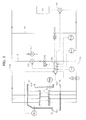
- Fig. 1 is a flow diagram of a flue-gas treatment system of the present embodiment.
- Fig. 2 is a diagram showing an example of a heat recovery unit (gas cooler) 9 included in the flue-gas treatment system in Fig. 1 and composed of heat transfer pipes and a heating-medium flow path system through which a heating medium is fed to the heat recovery unit 9.
- the flue-gas treatment system shown in Fig. 1 uses a heating-medium using unit 10 in place of the feedwater heater 100, which is shown in the flow diagram of the conventional flue-gas treatment system shown in Fig. 9 and which operates using the heat of a flue gas.
- the heating-medium flow path system between the heat recovery unit 9 and heating-medium using unit 10 shown in Fig. 1 differs from that in Fig. 9 only partially.
- feedwater from a feedwater source is fed through a feedwater (heating medium) pipe to the heat recovery unit 9 using a circulation pump 18 and reduces the temperature of the flue gas, and then the feedwater whose temperature has been increased is fed to the heating-medium using unit 10.
- a feedwater heating medium
- multiple heat recovery units 9 may be disposed in parallel in the flue-gas flow path.
- An inlet feedwater pipe 11a through which the heating medium is fed to the heat recovery unit 9 and an outlet feedwater pipe 11b into which the heat recovery unit 9 discharges the heating medium which has recovered heat constitute a heating-medium circulation line 11.
- a flue-gas temperature control valve CV1 and a heating-medium thermometer TE3 are disposed in the inlet feedwater pipe 11a so as to be adjacent to the inlets of the heat transfer pipes of the heat recovery unit 9.
- the flue-gas temperature control valve CV1 controls the gas temperature at the outlet of the heat recovery unit 9 in the flue-gas flow path by controlling the flow rate of the heating medium.
- the heating-medium thermometer TE3 measures the temperature of the heating medium in the inlet feedwater pipe 11a.
- a first heating-medium flowmeter FX1 is disposed in the inlet feedwater pipe 11a between the respective junctions of the inlet feedwater pipe 11a and a first heating-medium bypass line 13 and a second heating-medium bypass line 15 (to be discussed later).
- the first heating-medium flowmeter FX1 measures the flow rate of the heating medium in the inlet feedwater pipe 11a.
- the first heating-medium bypass line 13 and second heating-medium bypass line 15 connect the inlet feedwater pipe 11a and outlet feedwater pipe 11b, which are disposed between the heat recovery unit 9 and heating-medium using unit 10.
- the first heating-medium bypass line 13 connects the inlet feedwater pipe 11a and outlet feedwater pipe 11b in a position closer to the heat recovery unit 9 than to the heating-medium using unit 10.
- the second heating-medium bypass line 15 connects the inlet feedwater pipe 11a and outlet feedwater pipe 11b in a position closer to the heating-medium using unit 10 than to the heat recovery unit 9.
- An auxiliary pump 17 for feeding the heating medium from the outlet feedwater pipe 11b to the inlet feedwater pipe 11a and a first heating-medium flow-rate control valve CV2 are disposed in the first heating-medium bypass line 13.
- a second heating-medium flow-rate control valve CV3 for controlling the amount of the heating medium flowing from the inlet feedwater pipe 11a to the outlet feedwater pipe 11b while bypassing the heat recovery unit 9 and a second heating-medium flowmeter FX2 are disposed in the second heating-medium bypass line 15.
- the heat recovery unit 9 which is disposed in the flue-gas flow path of the boiler, includes an inlet flue-gas thermometer TE1 and an outlet flue-gas thermometer TE2.
- thermometers TE1, TE2, and TE3 and heating-medium flowmeters FX1 and FX2 are transmitted to a controller 20. Based on the measurement values, the controller 20 transmits operation signals to the control valves CV1, CV2, and CV3, auxiliary pump 17, and circulation pump 18.
- the auxiliary pump 17 disposed in the first heating-medium bypass line 13 feeds the heating medium from the outlet feedwater pipe 11b through the first heating-medium bypass line 13 to the inlet feedwater pipe 11a.
- the second heating-medium bypass line 15 connects an upstream portion of the inlet feedwater pipe 11a with respect to the first heating-medium bypass line 13 and a downstream portion of the outlet feedwater pipe 11b with respect thereto.
- the circulation pump 18 disposed in the inlet feedwater pipe 11a the heating medium is fed from the inlet feedwater pipe 11a through the second heating-medium bypass line 15 to the outlet feedwater pipe 11b.
- the second heating-medium bypass line 15 is provided with the second heating-medium flow-rate control valve CV3.
- the second heating-medium flow-rate control valve CV3 controls the flow rate of the heating medium using a value obtained by subtracting the amount of the heating medium used in the heat recovery unit 9 from a feed heating-medium amount request signal from a flue gas source such as the boiler 1, as a heating-medium bypass flow-rate set value in the second heating-medium bypass line 15.
- the flow rate of the heating medium in the second heating-medium bypass line 15 is controlled while measuring it using the second heating-medium flowmeter FX2.
- the second heating-medium flow-rate control valve (bypass heating-medium flow-rate control valve) CV3 is moved in a closing direction to reduce the bypass heating-medium flow rate.
- the bypass heating-medium flow-rate control valve CV3 is moved in an opening direction to increase the bypass heating-medium flow rate.
- the bypass heating-medium flow-rate control valve CV3 also detects the temperature of the heating medium flowing through the inlet feedwater pipe 11a using the heating-medium thermometer TE3 and controls the amount of the bypass heating medium, which is fed through the second heating-medium bypass line 15 to the inlet feedwater pipe 11a, so that the temperature of the heating medium becomes a preset temperature.
- the bypass heating-medium flow-rate control valve CV3 is moved in a closing direction to reduce the flow rate of the bypass heating-medium flowing through the second heating-medium bypass line 15; when the flue-gas temperature measured by the thermometer TE1 or TE2 is lower than the set temperature, the bypass heating-medium flow-rate control valve CV3 is moved in an opening direction to increase the flow rate of the bypass heating medium flowing through the second heating-medium bypass line 15.
- the opening or closing of the bypass heating-medium flow-rate control valve CV3 described above is controlled by performing PI (proportional-integral) control on the difference between the set flue-gas temperature of the heat recovery unit 9 and the actual flue-gas temperature thereof (the temperature measured by the thermometer TE1 or TE2).
- PI proportional-integral
- the temperature at the inlet of the heat recovery unit 9 in the flue-gas flow path (hereafter also simply referred to as the inlet temperature of the heat recovery unit 9) is measured by the thermometer TE1, or the temperature at the outlet of the heat recovery unit 9 in the flue-gas flow path (hereafter also simply referred to as the outlet temperature of the heat recovery unit 9) is measured by the thermometer TE2.
- the flue-gas temperature control valve CV1 in the inlet feedwater pipe 11a is kept closed, since there is no need to exchange heat between the flue gas and heating medium in the heat recovery unit 9.
- the sett temperature of the flue-gas in the flue-gas flow path in which the heat recovery unit 9 is disposed can be set voluntarily in accordance with the load of the boiler. Thus, adjustments are made to the average temperature in the region in which the heat recovery unit 9 is disposed, of the flue-gas flow path be kept at the set temperature.
- the flue-gas temperature control valve CV1 is opened with the degree of opening which is preset with respect to the flue-gas temperature at the inlet of the heat recovery unit 9 in accordance with the program setting.
- the flue-gas temperature control valve CV1 When the flue-gas temperature at the inlet of the heat recovery unit 9 is more than 90°C but the flue-gas temperature at the outlet thereof is less than 90°C (at this time, the heating medium temperature at the inlet of the heat recovery unit 9 is less than the set temperature of 72°C), the flue-gas temperature control valve CV1 is closed, and the second heating-medium flow-rate control valve CV3 in the second heating-medium bypass line 15 is fully opened in order for the outlet flue-gas temperature of the heat recovery unit 9 to be quickly increased to 90°C or more.
- the heating medium having a relatively high temperature from the outlet of the heat recovery unit 9 is passed through the first heating-medium bypass line 13 and circulated and fed to the inlet of the heat recovery unit 9.
- the first heat-medium flow-rate control valve CV2 which controls the flow rate of the heating medium in the first heating-medium bypass line 13, is closed.
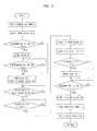
- FIG. 3 a heating-medium flow-rate control process performed from when the boiler is started to when the outlet flue-gas temperature of the heat recovery unit 9 is increased to 90°C or more.
- the circulation pump 18 is started, and the bypass heating-medium flow-rate control valve (second heating-medium flow-rate control valve) CV3 in the second heating-medium bypass line 15 is fully opened.
- the bypass heating-medium flow-rate control valve (second heating-medium flow-rate control valve) CV3 in the second heating-medium bypass line 15 is fully opened.
- all feedwater (heating medium) flowing into the inlet feedwater pipe 11a flows through the second heating-medium bypass line 15 while bypassing the heat recovery unit 9.
- the heat recovery unit 9 does not have to exchange the heat of the flue gas. Accordingly, the flue-gas temperature control valve CV1 in the inlet feedwater pipe 11a is kept closed.
- the flue-gas temperature control valve CV1 When the flue-gas temperature at the inlet or the outlet of the heat recovery unit 9 (the flue-gas temperature measured by the thermometer TE1 or TE2) exceeds 90°C, the flue-gas temperature control valve CV1 is opened with a predetermined degree of opening, and the second heating-medium flow-rate control valve CV3 is moved in a closed direction. At this time, the second heating-medium flow-rate control valve CV3 is controlled in a closing direction so that part of the heating medium fed from the circulation pump 18 to the heat recovery unit 9 flows through the second heating-medium bypass line 15.
- the flue-gas temperature control valve CV1 is controlled to start to open slightly and simultaneously the second heating-medium flow-rate control valve CV3 is controlled to start to close , the degree of opening of the flue-gas temperature control valve CV1 increases as the flue-gas temperature increases, and the amount of the heating medium flowing through the second heating-medium bypass line 15 is controlled to be reduced compared to the amount of the heating medium fed from the circulation pump 18.
- the flue-gas temperature control valve CV1 is opened to a predetermined degree of opening; and when the amount of the heating medium fed from the circulation pump 18 becomes the same as the amount of the heating medium fed to the heat recovery unit 9, the second heating-medium flow-rate control valve CV3 is fully closed.
- the second heating-medium flow-rate control valve CV3 is maintained with a predetermined degree of opening so that the heating medium is circulated to the heating-medium using unit 10 through the second heating-medium bypass line 15.
- the auxiliary pump 17 disposed in the first heating-medium bypass line 13 is automatically started.
- the heating medium from the outlet of the heat recovery unit 9 can be fed to the inlet thereof through the first heating-medium bypass line 13.
- a backup auxiliary pump 17' may be disposed in a position parallel with the auxiliary pump 17.
- the degree of opening of the first heating-medium flow-rate control valve CV2 is prevented from becoming the minimum degree of opening or less.
- the first heating-medium flow-rate control valve CV2 is prevented from being completely closed.
- the first heating-medium flow-rate control valve CV2 controls the flow rate of the heating medium so that the temperature detected by the heating-medium thermometer TE3 disposed in the inlet feedwater pipe 11a becomes a predetermined temperature (e.g., 72°C). Specifically, when the temperature detected by the heating-medium thermometer TE3 falls below 72 °C, part of the heating medium heated by the heat recovery unit 9 is passed through the heating-medium bypass line 13 and added to the heating medium flowing through the inlet feedwater pipe 11a by the auxiliary pump 17. Thus, the temperature of the heating medium flowing through the inlet feedwater pipe 11a is increased.
- a predetermined temperature e.g., 72°C
- the first heating-medium flow-rate control valve CV2 When the temperature measured by the thermometer TE1 or TE2 becomes higher than 90°C by a predetermined temperature (2°C), the first heating-medium flow-rate control valve CV2 is closed, and simultaneously the auxiliary pump 17 is stopped, or the heating medium is fed to a minimum flow line (not shown). Thus, the heating medium heated by the heat recovery unit 9 is fed to another heating-medium using unit 10 (not shown) without flowing through the first heating-medium bypass line 13, and heat is transferred in the other heating-medium using unit 10.
- the first heating-medium flow-rate control valve CV2 may be operated as follows.
- the heating-medium temperature detected by the heating-medium thermometer TE3 falls below 72°C
- part of the heating medium heated by the heat recovery unit 9 is passed through the first heating-medium bypass line 13 and added to the heating medium flowing through the inlet feedwater pipe 11a by the auxiliary pump 17.
- the temperature of the heating medium flowing through the inlet feedwater pipe 11a is increased, so that the temperature detected by the heating-medium thermometer TE3 exceeds 72°C.
- the operation to close the first heating-medium flow-rate control valve CV2 is started; then the auxiliary pump 17 is stopped; and then the first heating-medium flow-rate control valve CV2 is closed.
- the flue-gas temperature is the predetermined temperature or more, even if the temperature of the heating medium fed from the heating-medium circulation line 11 to the heat recovery unit 9 by the circulation pump 18 is reduced to the predetermined temperature or less, it is possible to prevent the inside of the flue-gas flow path downstream of the heat recovery unit 9 from being corroded due to condensation, as well as to stably keep high the temperature of the heating medium flowing through the heat recovery unit 9.
- the second heating-medium flow-rate control valve CV3 in the second heating-medium bypass line 15 is fully opened to circulate the heating medium through the second heating-medium bypass line 15.
- the flue-gas temperature measured by the thermometer TE1 or TE2 disposed at the inlet or outlet of the heat recovery unit 9 in the flue-gas flow path is lower than the preset temperature (e.g., 90°C)
- the flue-gas temperature control valve CV1 in the heating-medium circulation line 11 is kept closed.
- the heating medium confined within the heat recovery unit (gas cooler) 9 recovers heat from the flue gas and thus is gradually warmed.
- the heating medium may be flashed (be vaporized) and thus may cause a water hammer phenomenon, which may damage the heat transfer pipes in the heat recovery unit 9.
- the present embodiment is a configuration for stably operating a heat recovery unit (gas cooler) 9 during the startup of a boiler, without causing a water hammer phenomenon.
- this configuration is characterized in that a third heating-medium bypass line 19 is additionally disposed in the configuration shown in Fig. 2 .
- the third heating-medium bypass line 19 is disposed in parallel with a first heating-medium bypass line 13 and a second heating-medium bypass line 15 and connect an inlet feedwater pipe 11a and an outlet feedwater pipe 11b of a heat medium circulation line 11 so that the heating medium from the outlet of a heating-medium using unit 10 is returned to the inlet thereof while bypassing all of the gas cooler 9, first heating-medium bypass line 13, and second heating-medium bypass line 15.
- a first on/off valve 21 is disposed in the third heating-medium bypass line 19.
- a second on/off valve 22 is disposed in the inlet feedwater pipe 11a between the junction of the second heating-medium bypass line 15 and inlet feedwater pipe 11a and the junction of the third heating-medium bypass line 19 and inlet feedwater pipe 11a.
- a third on/off valve 23 is disposed in the outlet feedwater pipe 11b between the junction of the second heating-medium bypass line 15 and outlet feedwater pipe 11b and the junction of the third heating-medium bypass line 19 and outlet feedwater pipe 11b.
- auxiliary pumps 17 and 17' are disposed in parallel in the first heating-medium bypass line 13.
- a circulation pump 18 for circulating and feeding the heating medium to the gas cooler 9 is disposed in the inlet feedwater pipe 11a upstream of the junction of the third heating-medium bypass line 19 and inlet feedwater pipe 11a.
- a first flue-gas thermometer TE1 for measuring the temperature of the flue gas is disposed adjacent to the inlet of the gas cooler 9 in the flue-gas flow path; a second flue-gas thermometer TE2 for measuring the temperature of the flue gas is disposed adjacent to the outlet of the gas cooler 9 in the flue-gas flow path; and a heating-medium thermometer TE3 for measuring the temperature of the heating medium in the heating-medium circulation line 11 is disposed adjacent to the inlet of the gas cooler 9.
- thermometers TE1 and TE2 and heating-medium thermometer TE3 are inputted to a controller 20. Based on these pieces of information, the controller 20 outputs signals to the flue-gas temperature control valves CV1, CV2, and CV3 and on/off valves 21, 22, and 23.
- a method for operating a flue-gas treatment apparatus having the above configuration and used in a combustion apparatus including a boiler 1 during the startup of a combustion apparatus including a boiler 1 or immediately after igniting the burners of the combustion apparatus includes:
- a flue-gas treatment apparatus operating method which includes, instead of the above (b), when the flue-gas temperature measured by the first flue-gas thermometer TE1 or second flue-gas thermometer TE2 is lower than the preset temperature (the dew point of corrosive components in the flue gas; e.g., 90°C), opening the flue-gas temperature control valve CV1 and opening the second heating-medium flow-rate control valve CV3 in the second heating-medium bypass line 15 to circulate the heating medium between the second heating-medium bypass line 15 and heat recovery unit (gas cooler) 9, further opening the first heating-medium flow-rate control valve CV2 in the first heating-medium bypass line 13, and starting the auxiliary pump 17 to forcefully circulate the heating medium between the first heating-medium bypass line 13 and heat recovery unit 9.
- the preset temperature the dew point of corrosive components in the flue gas
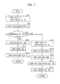
- FIG. 6 and 7 there will be described a heating-medium flow-rate control process according to the second embodiment which is performed until the outlet flue-gas temperature of the heat recovery unit 9 becomes 90°C or more during the startup of the combustion apparatus including the boiler 1 or immediately after igniting the combustion apparatus.
- Initial control steps include fully opening the first on/off valve 21, fully closing the second on/off valve 22 and third on/off valve 23 in the heating-medium circulation line 11, and starting the circulation pump 18 so that the heating medium flowing into the outlet feedwater pipe 11b is circulated through the third heating-medium bypass line 19, heating-medium using unit 10, and inlet feedwater pipe 11a.
- Subsequent control steps include steps according to the flow of Fig. 6 and steps according to the flow of Fig. 7 .
- the control steps includes when the flue-gas temperature measured by the first flue-gas thermometer TE1 or second flue-gas thermometer TE2 disposed at the inlet or outlet of the gas cooler 9 in the flue-gas flow path is lower than or equal to the preset temperature (the dew point of corrosive components in the flue gas; e.g., 90°C), opening the flue-gas temperature control valve CV1 in the heating-medium circulation line 11 and opening the second heating-medium flow-rate control valve CV3 in the second heating-medium bypass line 15 so that the heating medium in the gas cooler 9 naturally circulates between the gas cooler 9 and second heating-medium bypass line 15.
- the preset temperature the dew point of corrosive components in the flue gas
- the control steps also include when the flue-gas temperature measured by the first flue-gas thermometer TE1 or second flue-gas thermometer TE2 at the inlet or outlet of the heat recovery unit 9 in the flue-gas flow path becomes higher than the preset temperature (e.g., 90°C), fully closing the first on/off valve 21 in the third heating-medium bypass line 19, fully opening the second on/off valve 22 and third on/off valve 23 in the heating-medium circulation line 11, opening the flue-gas temperature control valve CV1 in the heating-medium circulation line 11, and starting to close the second heat medium flow rate control valve CV3 so that the flow rates of the heating medium flowing through the heating-medium bypass lines 13 and 15 are gradually reduced.
- the preset temperature e.g. 90°C
- the control steps includes when the flue-gas temperature measured by the first flue-gas thermometer TE1 or second flue-gas thermometer TE2 at the inlet or outlet of the gas cooler 9 in the flue-gas flow path is lower than or equal to the preset temperature (the dew point of corrosive components in the flue gas; e.g., 90°C), opening the flue-gas temperature control valve CV1 in the heating-medium circulation line 11 and the second heating-medium flow-rate control valve CV3 in the second heating-medium bypass line 15 and opening the first heating-medium flow-rate control valve CV2 in the first heating-medium bypass line 13 so that the feedwater (heating medium) is circulated among the gas cooler 9, first heating-medium bypass line 13, and second heating-medium bypass line 15. Since the auxiliary pump 17 is disposed in the second heating-medium bypass line 15, the heating medium can be more smoothly circulated between the heat recovery unit 9 and heating-medium using unit 10 by starting the auxiliary pump 17.
- the preset temperature the dew point
- the control steps also includes when the flue-gas temperature measured by the first flue-gas thermometer TE1 or second flue-gas thermometer TE2 at the inlet or outlet of the gas cooler 9 in the flue-gas flow path becomes higher than the preset temperature (e.g., 90°C), fully closing the first on/off valve 21 in the third heating-medium bypass line 19, fully opening the second on/off valve 22 and third on/off valve 23 in the heating-medium circulation line 11, starting to open the flue-gas temperature control valve CV1, stopping the operating auxiliary pump 17, and simultaneously starting to close the first heating-medium flow-rate control valve CV2 and second heating-medium flow-rate control valve CV3 so that the flow rates of the heating medium flowing through the heating medium bypass lines 13 and 15 are gradually reduced.
- the preset temperature e.g. 90°C
- a second heating-medium flow-rate control valve CV3 as shown in Fig. 8 may be disposed in place of the auxiliary pump 17' in Fig. 5 , which is a backup of the auxiliary pump 17.
- the second heating-medium bypass line 15 can be removed. Even in this case, advantageous effects similar to those of the configuration in Fig. 5 can be obtained.
Landscapes
- Engineering & Computer Science (AREA)
- Mechanical Engineering (AREA)
- General Engineering & Computer Science (AREA)
- Treating Waste Gases (AREA)
- Chimneys And Flues (AREA)
- Air Supply (AREA)
Abstract
Description
- The present invention relates to a flue-gas treatment apparatus for purifying a flue gas discharged from a combustion apparatus, such as a boiler, used in a thermal power system, such as a thermal power plant, and an operating method thereof.
-
Fig. 9 is a flow diagram of a wet flue-gas treatment apparatus for use in a thermal power plant disclosed in Japanese Patent No.4725985 - In
Fig. 9 , a flue gas discharged from aboiler 1 disposed in a thermal power plant, an exhaust-gas emission apparatus, or the like is introduced to adenitrification unit 2 so that nitrogen oxides are removed from the flue gas. The resulting flue gas is subjected to heat exchange with combustion air to be fed to theboiler 1 in anair preheater 3. The resulting flue gas is introduced into anelectrostatic precipitator 4 so that dust is mostly removed from the flue gas. The resulting flue gas is pressurized by an induceddraft fan 5 and introduced into adesulfurization unit 6 so that sulfur oxides (SOx) are removed from the flue gas. The resulting flue gas is pressurized by a boost-upfan 7 and discharged from asmokestack 8. - Further, in the configuration shown in
Fig. 9 , aheat recovery unit 9 is disposed adjacent to the inlet of theelectrostatic precipitator 4 in the flue-gas flow path; afeedwater line 106 for feeding water to theboiler 1 is disposed; afeedwater heater 100 is disposed in thefeedwater line 106; a heating-medium circulation pipe 101 for communicating theheat recovery unit 9 andfeedwater heater 100 is disposed; a heating-medium bypass pipe 102 which allows the heating medium on the inlet side of the heat recovery unit to circulate to thefeedwater heater 100 while bypassing theheat recovery unit 9 is disposed in the heating-medium circulation pipe 101; and a heating-medium flow-rate control valve 103 is disposed in the heating-medium bypass pipe 102. - A method for operating the flue-gas treatment apparatus constitute of the composition described above is; during the startup of the
boiler 1 or immediately after igniting theboiler 1 includes: when the temperature of the flue gas upstream side of theprecipitator 4 in the flue-gas flow path is lower than the dew point of corrosive components in the flue gas, opening the heating-medium flow-rate control valve 103 to cause the heating medium to bypass theheat recovery unit 9 or to reduce the amount of the heating medium flowing into theheat recovery unit 9 so as to reduce the amount of heat exchange therein; subsequently, when the heat is recovered from the flue gas in theheat recovery unit 9 and the outlet flue-gas temperature of theheat recovery unit 9 reaches a set value or more, closing the heating-medium flow-rate control valve 103 in the heating-medium bypass pipe 102 so that the heating medium which has recovered heat from the flue gas in theheat recovery unit 9 is introduced into thefeedwater heater 100 through the heating-medium circulation pipe 101; and after heating boiler feedwater, reintroducing the heating medium into theheat recovery unit 9 through the heating-medium circulation pipe 101 so that the flue-gas treatment apparatus is placed in a normal operating state. - Other known configurations include configurations in which a heat recovery unit is disposed in the flue-gas flow path of a boiler and in which a heating-medium circulation pipe through which a heating medium (water) that has recovered heat in the heat recovery unit is disposed and the heating medium is circulated and supplied to a boiler condensate heater (
Patent Literatures 2 and 3). - 1
- [Patent Literature 1] Japanese Patent No.
4725985 - [Patent Literature 2] Japanese Patent No.
4959156 - [Patent Literature 3] Japanese Unexamined Patent Application Publication No.
2011-94962 - For the above flue-gas treatment apparatuses of the conventional art upon recovering heat of flue-gas discharged from boiler using
heat recovery unit 9, when a heating medium (feedwater) which is fed to theheat recovery unit 9 has a low temperature during the startup of the boiler, during which the flue-gas temperature is gradually increased, theheat recovery unit 9 discharges a flue gas having a low and unstable temperature. - During the startup or stop of a thermal power system, the conditions for a flue gas discharged from a boiler or the conditions of a heating medium used to generate power using turbines are often not as planned. In particular, during the startup of a thermal power system, the temperature of a heating medium (water) is often lower than the planned temperature. Even immediately after the thermal power system is started, the flue gas must be cooled to the planned temperature (90°C or the like), since the boiler is incinerating fuel. In this case, by causing the heating medium to bypass the
heat recovery unit 9 and thus reducing the amount of the heating medium fed thereto, flue-gas temperature at the outlet of theheat recovery unit 9 can be controlled in terms of heat calculation. However, in actually, when the amount of the heating medium flowing into theheat recovery unit 9 is reduced, a deviation is generated in amounts of heating medium flow into the respective heat transfer pipes of theheat recovery unit 9. This prevents uniform heat exchange in theheat recovery unit 9. - An object of the present invention is to avoid the destabilization of flue-gas temperature at the outlet of the heat recovery apparatus and the placement in a corrosive environment of the heat recovery apparatus, the wall surface of the flue-gas flow path downstream side of the heat recovery apparatus, and the devices in the downstream side of flue-gas flow path, because of instability of the supply amount and the temperature of the heating-medium caused by an effect of variation of the amount and the temperature of the flue-gas during startup or stop of the thermal power system.
- The above obj ect is achieved by the following solving means. A first aspect of the present invention provides a flue-gas treatment apparatus in which a precipitator (4) that treats dust contained in a flue gas of a combustion apparatus including a boiler (1) and a desulfurization unit (6) that treats sulfur oxides contained in the flue gas are disposed sequentially from an upstream side of a flue-gas flow path, wherein, a heat recovery unit (9) is disposed in the flue-gas flow path at an inlet of the precipitator (4), a heating-medium using unit (10) is disposed in a region independent of the flue-gas flow path, a heating-medium circulation line (11) through which a heating medium is circulated and fed is disposed between the heat recovery unit (9) and the heating-medium using unit (10), a flue-gas temperature control valve (CV1) for controlling a temperature of the flue gas in the flue-gas flow path is disposed in the heating-medium circulation line (11), a first heating-medium bypass line (13) that allows the heating medium from an outlet of the heat recovery unit (9) to circulate to an inlet of the heat recovery unit (9) while bypassing the heating-medium using unit (10) is disposed in the heating-medium circulation line (11), a first heating-medium flow-rate control valve (CV2) and an auxiliary pump (17) that feed the heating medium from the outlet of the heat recovery unit (9) to the inlet of the heat recovery unit (9) are disposed in the first heating-medium bypass line (13), a second heating-medium bypass line (15) that allows the heating medium from an outlet of the heating-medium using unit (10) to return to an inlet of the heating-medium using unit (10) while bypassing the heat recovery unit (9) and the first heating-medium bypass line (13) is disposed in the heating-medium circulation line (11), a second heating-medium flow-rate control valve (CV3) is disposed in the second heating-medium bypass line (15), a circulation pump (18) that circulates and feeds the heating medium to the heat recovery unit (9) is disposed in the heating-medium circulation line (11) upstream of a junction of the heating-medium circulation line (11) and the second heating-medium bypass line (15), a first flue-gas thermometer (TE1) that measures the temperature of the flue gas is disposed at the inlet of the heat recovery unit (9) in the flue-gas flow path, a second flue-gas thermometer (TE2) that measures the temperature of the flue gas is disposed at the outlet of the heat recovery unit (9) in the flue-gas flow path, and a heating-medium thermometer (TE3) that measures the temperature of the heating medium is disposed in the heating-medium circulation line (11) at the inlet of the heat recovery unit (9).
- A second aspect of the present invention provides a method for operating a flue-gas treatment apparatus during startup of a combustion apparatus including a boiler (1) or immediately after igniting burners of the combustion apparatus, the flue-gas treatment apparatus being a flue-gas treatment apparatus in which a precipitator (4) that treats dust contained in a flue gas of the combustion apparatus including the boiler (1) and a desulfurization unit (6) that treats sulfur oxides contained in the flue gas are disposed sequentially from an upstream side of a flue-gas flow path, a heat recovery unit (9) is disposed in the flue-gas flow path at an inlet of the precipitator (4), a heating-medium using unit (10) is disposed in a region independent of the flue-gas flow path, a heating-medium circulation line (11) through which a heating medium is circulated and fed is disposed between the heat recovery unit (9) and the heating-medium using unit (10), a flue-gas temperature control valve (CV1) for controlling a temperature of the flue gas in the flue-gas flow path is disposed in the heating-medium circulation line (11), a first heating-medium bypass line (13) that allows the heating medium from an outlet of the heat recovery unit (9) to circulate to an inlet of the heat recovery unit (9) while bypassing the heating-medium using unit (10) is disposed in the heating-medium circulation line (11), a first heating-medium flow-rate control valve (CV2) and an auxiliary pump (17) that feed the heating medium from the outlet of the heat recovery unit (9) to the inlet of the heat recovery unit (9) are disposed in the first heating-medium bypass line (13), a second heating-medium bypass line (15) that allows the heating medium from an outlet of the heating-medium using unit (10) to return to an inlet of the heating-medium using unit (10) while bypassing the heat recovery unit (9) and the first heating-medium bypass line (13) is disposed in the heating-medium circulation line (11), a second heating-medium flow-rate control valve (CV3) is disposed in the second heating-medium bypass line (15), a circulation pump (18) that circulates and feeds the heating medium to the heat recovery unit (9) is disposed in the heating-medium circulation line (11) upstream of a junction of the heating-medium circulation line (11) and the second heating-medium bypass line (15), a first flue-gas thermometer (TE1) that measures the temperature of the flue gas is disposed at the inlet of the heat recovery unit (9) in the flue-gas flow path, a second flue-gas thermometer (TE2) that measures the temperature of the flue gas is disposed at the outlet of the heat recovery unit (9) in the flue-gas flow path, and a heating-medium thermometer (TE3) that measures the temperature of the heating medium is disposed in the heating-medium circulation line (11) at the inlet of the heat recovery unit (9), wherein, the method comprising: (a) starting the circulation pump (18) in the heating-medium circulation line (11) and fully opening the second heating-medium flow-rate control valve (CV3) in the second heating-medium bypass line (15) to circulate the heating medium through the second heating-medium bypass line (15) ; (b) when the temperature of the flue gas measured by the first flue-gas thermometer (TE1) disposed at the inlet of the heat recovery unit (9) or the temperature of the flue gas measured by the second flue-gas thermometer (TE2) disposed at the outlet of the heat recovery unit (9) in the flue-gas flow path is lower than a preset temperature (the dew point of corrosive components in the flue-gas; e.g., 90°C) keeping the flue-gas temperature control valve (CV1) in the heating-medium circulation line (11) closed; (c) when the temperature of the flue gas measured by the first flue-gas thermometer (TE1) at the inlet of the heat recovery unit (9) in the flue-gas flow path or the temperature of the flue gas measured by the second flue-gas thermometer (TE2) at the outlet of the heat recovery unit (9) in the flue-gas flow path becomes higher than the preset temperature, starting to open the flue-gas temperature control valve (CV1) to start to circulate the heating medium through the heating-medium circulation line (11) and simultaneously starting to close the second heating-medium flow-rate control valve (CV3) in the second heating-medium bypass line (15); (d) starting to open the first heating-medium flow-rate control valve (CV2) in the first heating-medium bypass line (13) with the second heating-medium flow-rate control valve (CV3) not completely closed and simultaneously starting the auxiliary pump (17) to feed the heating medium into the first heating-medium bypass line (13); (e) controlling the degree of opening of the first heating-medium flow-rate control valve (CV2) in the first heating-medium bypass line (13) so that the temperature of the heating medium does not fall below a specified temperature (e.g. , 72°C), on the basis of the temperature of the heating medium measured by the heating-medium thermometer (TE3) disposed in the heating-medium circulation line (11) at the inlet of the heat recovery unit (9); and (f) when the temperature of the flue gas measured by the first flue-gas thermometer (TE1) disposed at the inlet of the heat recovery unit (9) or the temperature of the flue gas measured by the second flue-gas thermometer (TE2) disposed at the outlet of the heat recovery unit (9) in the flue-gas flow path becomes higher than the preset temperature (the dew point of corrosive components in the flue-gas; e.g., 90°C) by a predetermined temperature (e.g., 2°C), stopping to operate the auxiliary pump (17) in the first heating-medium bypass line (13) and subsequently closing the first heating-medium flow-rate control valve (CV2).
- A third aspect of the present invention provides a method for operating a flue-gas treatment apparatus during startup of a combustion apparatus including a boiler (1) or immediately after igniting burners of the combustion apparatus, the flue-gas treatment apparatus being a flue-gas treatment apparatus in which a precipitator (4) that treats dust contained in a flue gas of the combustion apparatus including the boiler (1) and a desulfurization unit (6) that treats sulfur oxides contained in the flue gas are disposed sequentially from an upstream side of a flue-gas flow path, a heat recovery unit (9) is disposed in the flue-gas flow path at an inlet of the precipitator (4), a heating-medium using unit (10) is disposed in a region independent of the flue-gas flow path, a heating-medium circulation line (11) through which a heating medium is circulated and fed is disposed between the heat recovery unit (9) and the heating-medium using unit (10), a flue-gas temperature control valve (CV1) for controlling a temperature of the flue gas in the flue-gas flow path is disposed in the heating-medium circulation line (11), a first heating-medium bypass line (13) that allows the heating medium from an outlet of the heat recovery unit (9) to circulate to an inlet of the heat recovery unit (9) while bypassing the heating-medium using unit (10) is disposed in the heating-medium circulation line (11), a first heating-medium flow-rate control valve (CV2) and an auxiliary pump (17) that feed the heating medium from the outlet of the heat recovery unit (9) to the inlet of the heat recovery unit (9) are disposed in the first heating-medium bypass line (13), a second heating-medium bypass line (15) that allows the heating medium from an outlet of the heating-medium using unit (10) to return to an inlet of the heating-medium using unit (10) while bypassing the heat recovery unit (9) and the first heating-medium bypass line (13) is disposed in the heating-medium circulation line (11), a second heating-medium flow-rate control valve (CV3) is disposed in the second heating-medium bypass line (15), a circulation pump (18) that circulates and feeds the heating medium to the heat recovery unit (9) is disposed in the heating-medium circulation line (11) upstream of a junction of the heating-medium circulation line (11) and the second heating-medium bypass line (15), a first flue-gas thermometer (TE1) that measures the temperature of the flue gas is disposed at the inlet of the heat recovery unit (9) in the flue-gas flow path, a second flue-gas thermometer (TE2) that measures the temperature of the flue gas is disposed at the outlet of the heat recovery unit (9) in the flue-gas flow path, and a heating-medium thermometer (TE3) that measures the temperature of the heating medium is disposed in the heating-medium circulation line (11) at the inlet of the heat recovery unit (9), wherein, the method comprising: (a) starting the circulation pump (18) in the heating-medium circulation line (11) and fully opening the second heating-medium flow-rate control valve (CV3) in the second heating-medium bypass line (15) to circulate the heating medium through the second heating-medium bypass line (15); (b) when the temperature of the flue gas measured by the first flue-gas thermometer (TE1) disposed at the inlet of the heat recovery unit (9) or the temperature of the flue gas measured by the second flue-gas thermometer (TE2) disposed at the outlet of the heat recovery unit (9) in the flue-gas flow path is lower than a preset temperature (the dew point of corrosive components in the flue-gas; e.g., 90°C), keeping the flue-gas temperature control valve (CV1) in the heating-medium circulation line (11) closed; (c) when the temperature of the flue gas measured by the first flue-gas thermometer (TE1) at the inlet of the heat recovery unit (9) in the flue-gas flow path or the temperature of the flue gas measured by the second flue-gas thermometer (TE2) at the outlet of the heat recovery unit (9) in the flue-gas flow path becomes higher than the preset temperature, starting to open the flue-gas temperature control valve (CV1) to start to circulate the heating medium through the heating-medium circulation line (11) and simultaneously starting to close the second heating-medium flow-rate control valve (CV3) in the second heating-medium bypass line (15); (d) starting to open the first heating-medium flow-rate control valve (CV2) in the first heating-medium bypass line (13) with the second heating-medium flow-rate control valve (CV3) not completely closed and simultaneously starting the auxiliary pump (17) to feed the heating medium into the first heating-medium bypass line (13); (e) controlling the degree of opening of the first heating-medium flow-rate control valve (CV2) in the first heating-medium bypass line (13) so that the temperature of the heating medium does not fall below a specified temperature (e. g. , 72°C), on the basis of the temperature of the heating medium measured by the heating-medium thermometer (TE3) disposed in the heating-medium circulation line (11) at the inlet of the heat recovery unit (9); and (f) when the temperature of the heating medium measured by the heating-medium thermometer (TE3) disposed in the heating-medium circulation line (11) at the inlet of the heat recovery unit (9) becomes higher than the preset temperature(e.g., 72°C) by a predetermined temperature(e.g., 2°C), stopping to operate the auxiliary pump (17) in the first heating-medium bypass line (13) and subsequently closing the first heating-medium flow-rate control valve (CV2).
- A fourth aspect of the present invention provides a flue-gas treatment apparatus in which a precipitator (4) that treats dust contained in a flue gas of a combustion apparatus including a boiler (1) and a desulfurization unit (6) that treats sulfur oxides included in the flue gas are disposed sequentially from an upstream side of a flue-gas flow path, wherein, a heat recovery unit (9) is disposed in the flue-gas flow path at an inlet of the precipitator (4), a heating-medium using unit (10) is disposed in a region independent of the flue-gas flow path, a heating-medium circulation line (11) through which a heating medium is circulated and fed is disposed between the heat recovery unit (9) and the heating-medium using unit (10), a flue-gas temperature control valve (CV1) for controlling a temperature of the flue gas in the flue-gas flow path is disposed in the heating-medium circulation line (11), a first heating-medium bypass line (13) that allows the heating medium from an outlet of the heat recovery unit (9) to circulate to an inlet of the heat recovery unit (9) while bypassing the heating-medium using unit (10) is disposed in the heating-medium circulation line (11), a first heating-medium flow-rate control valve (CV2) and an auxiliary pump (17) that feed the heating medium from the outlet of the heat recovery unit (9) to the inlet of the heat recovery unit (9) are disposed in the first heating-medium bypass line (13), a second heating-medium bypass line (15) that allows the heating medium from an outlet of the heating-medium using unit (10) to return to an inlet of the heating-medium using unit (10) while bypassing the heat recovery unit (9) and the first heating-medium bypass line (13) is disposed in the heating-medium circulation line (11), a second heating-medium flow-rate control valve (CV3) is disposed in the second heating-medium bypass line (15), a circulation pump (18) that circulates and feeds the heating medium to the heat recovery unit (9) is disposed in the heating-medium circulation line (11) upstream of a junction of the heating-medium circulation line (11) and the second heating-medium bypass line (15), a first flue-gas thermometer (TE1) that measures the temperature of the flue gas is disposed at the inlet of the heat recovery unit (9) in the flue-gas flow path, a second flue-gas thermometer (TE2) that measures the temperature of the flue gas is disposed at the outlet of the heat recovery unit (9) in the flue-gas flow path, a heating-medium thermometer (TE3) that measures the temperature of the heating medium is disposed in the heating-medium circulation line (11) at the inlet of the heat recovery unit (9), a third heating-medium bypass line (19) that allows the heating medium from the outlet of the heating-medium using unit (10) to return to the inlet of the heating-medium using unit (10) while bypassing the heat recovery unit (9), the first heating-medium bypass line (13), and the second heating-medium bypass line (15) is disposed in the heating-medium circulation line (11), a first on/off valve (21) is disposed in the third heating-medium bypass line (19), a second on/off valve (22) is disposed in the heating-medium circulation line (11) between a junction of the heating-medium circulation line (11) and the second heating-medium bypass line (15) and a junction of the heat medium circulation line (11) and the third heating-medium bypass line (19), a third on/off valve (23) is disposed in the heating-medium circulation line (11) between a junction of the heating-medium circulation line (11) and the second heating-medium bypass line (15) and a junction of the heat medium circulation line (11) and the third heating-medium bypass line (19), and the second on/off valve (22) and third on/off valve (23) are disposed upstream and downstream, respectively, in the heating-medium circulation line (11).
- A fifth aspect of the present invention provides a method for operating a flue-gas treatment apparatus during startup of a combustion apparatus including a boiler (1) or immediately after igniting burners of the combustion apparatus, the flue-gas treatment apparatus being a flue-gas treatment apparatus in which a precipitator (4) that treats dust contained in a flue gas of the combustion apparatus including the boiler (1) and a desulfurization unit (6) that treats sulfur oxides included in the flue gas are disposed sequentially from an upstream side of a flue-gas flow path, a heat recovery unit (9) is disposed in the flue-gas flow path at an inlet of the precipitator (4) are provided, a heating-medium using unit (10) is disposed in a region independent of the flue-gas flow path, a heating-medium circulation line (11) through which a heating medium is circulated and fed is disposed between the heat recovery unit (9) and the heating-medium using unit (10), a flue-gas temperature control valve (CV1) for controlling a temperature of the flue gas in the flue-gas flow path is disposed in the heating-medium circulation line (11), a first heating-medium bypass line (13) that allows the heating medium from an outlet of the heat recovery unit (9) to circulate to an inlet of the heat recovery unit (9) while bypassing the heating-medium using unit (10) is disposed in the heating-medium circulation line (11), a first heating-medium flow-rate control valve (CV2) and an auxiliary pump (17) that feed the heating medium from the outlet of the heat recovery unit (9) to the inlet of the heat recovery unit (9) are disposed in the first heating-medium bypass line (13), a second heating-medium bypass line (15) that allows the heating medium from an outlet of the heating-medium using unit (10) to return to an inlet of the heating-medium using unit (10) while bypassing the heat recovery unit (9) and the first heating-medium bypass line (13) is disposed in the heating-medium circulation line (11), a second heating-medium flow-rate control valve (CV3) is disposed in the second heating-medium bypass line (15), a circulation pump (18) that circulates and feeds the heating medium to the heat recovery unit (9) is disposed in the heating-medium circulation line (11) upstream of a junction of the heating-medium circulation line (11) and the second heating-medium bypass line (15), a first flue-gas thermometer (TE1) that measures the temperature of the flue gas is disposed at the inlet of the heat recovery unit (9) in the flue-gas flow path, a second flue-gas thermometer (TE2) that measures the temperature of the flue gas is disposed at the outlet of the heat recovery unit (9) in the flue-gas flow path, a heating-medium thermometer (TE3) that measures the temperature of the heating medium is disposed in the heating-medium circulation line (11) at the inlet of the heat recovery unit (9), a third heating-medium bypass line (19) that allows the heating medium from the outlet of the heating-medium using unit (10) to return to the inlet of the heating-medium using unit (10) while bypassing the heat recovery unit (9), the first heating-medium bypass line (13), and the second heating-medium bypass line (15) is disposed in the heating-medium circulation line (11), a first on/off valve (21) is disposed in the third heating-medium bypass line (19), a second on/off valve (22) is disposed in the heating-medium circulation line (11) between a junction of the heating-medium circulation line (11) and the second heating-medium bypass line (15) and a junction of the heat medium circulation line (11) and the third heating-medium bypass line (19), a third on/off valve (23) is disposed in the heating-medium circulation line (11) between a junction of the heating-medium circulation line (11) and the second heating-medium bypass line (15) and a junction of the heat medium circulation line (11) and the third heating-medium bypass line (19), and the second on/off valve (22) and third on/off valve (23) are disposed upstream and downstream, respectively, in the heating-medium circulation line (11), wherein, the method comprising: (a) fully opening the first on/off valve (21), fully closing the second on/off valve (22) and the third on/off valve (23), and starting the circulation pump (18) in the heating-medium circulation line (11) to circulate the heating medium between the third heating-medium bypass line (19) and the heating-medium using unit (10) ; (b) when the temperature of the flue gas measured by the first flue-gas thermometer (TE1) disposed at the inlet of the heat recovery unit (9) in the flue-gas flow path or the temperature of the flue gas measured by the second flue-gas thermometer (TE2) disposed at the outlet of the heat recovery unit (9) in the flue-gas flow path is lower than a preset temperature (the dew point of corrosive components in the flue-gas; e.g., 90°C), opening the flue-gas temperature control valve (CV1) and opening the second heating-medium flow-rate control valve (CV3) in the second heating-medium bypass line (15) so that the heating medium naturally circulates between the second heating-medium bypass line (15) and the heat recovery unit (9); and (c) when the temperature of the flue gas measured by the first flue-gas thermometer (TE1) at the inlet of the heat recovery unit (9) in the flue-gas flow path or the temperature of the flue gas measured by the second flue gas thermometer (TE2) at the outlet of the heat recovery unit (9) in the flue-gas flow path becomes higher than the preset temperature (the dew point of corrosive components in the flue-gas; e. g. , 90°C), opening the second on/off valve (22) and the third on/off valve (23), closing the first on/off valve (21), and simultaneously starting to close the first heating-medium flow-rate control valve (CV2) in the first heating-medium bypass line (13) and the second heating-medium flow-rate control valve (CV3) in the second heating-medium bypass line (15) to start to circulate the heating medium between the heat recovery unit (9) and the heating-medium using unit (10) through the heating-medium circulation line (11).
- A sixth aspect of the present invention provides a method for operating a flue-gas treatment apparatus comprising the method of the fifth aspect, wherein the method comprises, instead of step (b), (d) when the temperature of the flue gas measured by the first flue-gas thermometer (TE1) disposed at the inlet of the heat recovery unit (9) in the flue-gas flow path or the temperature of the flue gas measured by the second flue-gas thermometer (TE2) disposed at the outlet of the heat recovery unit (9) in the flue-gas flow path is lower than a preset temperature (the dew point of corrosive components in the flue-gas; e.g., 90°C), opening the flue-gas temperature control valve (CV1) and opening the second heating-medium flow-rate control valve (CV3) in the second heating-medium bypass line (15) to circulate the heating medium between the second heating-medium bypass line (15) and the heat recovery unit (9), the method further comprising: opening the first heating-medium flow-rate control valve (CV2) in the first heating-medium bypass line (13) and starting the auxiliary pump (17) to forcefully circulate the heating medium between the first heating-medium bypass line (13) and the heat recovery unit (9).
- According to the first, second, or third aspect of the present invention, the heating-medium circulation line (11) through which the heating medium is circulated and fed is disposed between the heat recovery unit (9) and heating-medium using unit (10), the first heating-medium bypass line (13) and second heating-medium bypass line (15) that allow the heating medium from the outlet of the heat recovery unit (9) to circulate to the inlet of the heat recovery unit (9) while bypassing the heating-medium using unit (10) are disposed in the heating-medium circulation line (11), and the first heating-medium flow-rate control valve (CV2) and second heating-medium flow-rate control valve (CV3) are disposed in the first heating-medium bypass line (13) and second heating-medium bypass line (15), respectively. During the startup of the combustion apparatus including the boiler (1) or immediately after igniting burners of the combustion apparatus, the flow rates of the heating-medium flowing through the heating-medium bypass lines (13, 15) can be controlled by controlling the degrees of opening of the first heating-medium flow-rate control valve (CV2) and second heating-medium flow-rate control valve (CV3).
- Thus, according to the first, second, or third aspect of the present invention, when the heat recovery unit (9) recovers heat from a flue gas from the combustion apparatus such as the boiler (1) during the startup of a thermal power system or the like and when the temperature of the heating medium is low, it is possible to prevent the heating surface of the heat recovery unit (9) from being corroded due to condensation, as well as to stably keep the flue-gas temperature at the outlet of the heat recovery unit (9) in the planned state.
- In other words, according to the present invention, the planned heating-medium circulation rate of the heat recovery unit (9) can be maintained owing to the first heating-medium bypass line (13) having the auxiliary pump (17) and first heating-medium flow-rate control valve (CV2) thereon, the second heating-medium bypass line (15) having the second heating-medium flow-rate control valve (CV3) thereon, which connect the heat recovery unit (9) and heating-medium using unit (10), the operation of the auxiliary pump (17), and the heating-medium flow-rate control valves (CV2, CV3). Further, owing to the circulation pump (18) disposed in the heating-medium circulation line (11), stable flue-gas temperature at the outlet of the heat recovery unit (9) and stable heating-medium temperature at the inlet of the heat recovery unit (9) can be achieved independently of the variations in the flow rate and temperature of the heating medium from the thermal power system. From these stability of the temperature, it is possible to avoid the heat recovery unit (9), the wall of the flue-gas flow path downstream thereof, and the units in the downstream flue-gas flow path from being placed in a corrosive environment, as well as to achieve stable start of the combustion apparatus.
- According to the fourth or fifth aspects of the present invention, in the system configuration in which the heat recovery unit (9) for recovering heat from the flue gas from the combustion apparatus such as the boiler (1) is disposed independently; there is no heating-medium heating mechanism using steam injection; and heat recovered by the heat recovery unit (9) is used for boiler feedwater, if the flue-gas temperature measured by the first flue-gas thermometer (TE1) or second flue-gas thermometer (TE2) disposed at the inlet or outlet of the heat recovery unit (9) in the flue-gas flow path is lower than the preset temperature (the dew point of corrosive components in the flue gas; e.g., 90°C), the heating-medium circulation system between the heat recovery unit (9) and heating-medium using unit (10) is started in a state in which the heating-medium circulation system between the heat recovery unit (9) and heating-medium using unit (10) is separated. Thus, during the startup of the boiler (1) or the like, it is possible to reduce the risk that the heating medium warmed by the heat of the flue gas in the flue-gas flow path may be naturally convected in the system of the heat recovery unit (9) and thus the heating medium in the heat recovery unit (9) may be warmed locally and flashed (vaporized), as well as to avoid an increase in the time in which the heat recovery unit (9) is placed in a corrosive environment.
- According to the sixth aspect of the present invention, when the heating-medium circulation system between the heat recovery unit (9) and heating-medium using unit (10) is started in a state in which the heating-medium circulation system between the heat recovery unit (9) and heating-medium using unit (10) is separated, if the flue-gas temperature measured by the second flue-gas thermometer (TE2) disposed at the outlet of the heat recovery unit (9) in the flue-gas flow path is lower than the preset temperature (the dew point of corrosive components in the flue gas; e. g. , 90°C), the heating medium warmed by the heat of the flue gas at the outlet of the air preheater (3) is forcefully convected in the system of the heat recovery unit (9) during the startup of the boiler (1) or the like, during which the flue-gas temperature is low. Thus, compared to the fifth aspect of the present invention, it is possible to quickly warm the heating medium in the heat recovery unit (9) locally and to reduce the risk that the heating medium may be flashed (vaporized).
-
-
Fig. 1 is a flow diagram of a flue-gas treatment system of a first embodiment of the present invention. -
Fig. 2 is a diagram showing details of a heating-medium flow path system for a heat recovery unit of the flue-gas treatment system inFig. 1 . -
Fig. 3 is a flowchart showing a control process of the heating-medium flow path system for the heat recovery unit inFig. 1 . -
Fig. 4 is a flowchart showing another control process of the heating-medium flow path system of the heat recovery unit inFig. 1 . -
Fig. 5 is a diagram showing details of a heating-medium flow path system for a heat recovery unit of a flue-gas treatment system of a second embodiment of the present invention. -
Fig. 6 is a flowchart showing a control process of the heating-medium flow path system for the heat recovery unit inFig. 5 . -
Fig. 7 is a flowchart showing a control process of the heating-medium flow path system for the heat recovery unit inFig. 5 . -
Fig. 8 is a diagram showing details of the heating-medium flow path system for a heat recovery unit of a flue-gas treatment system, which is a modification of the second embodiment of the present invention. -
Fig. 9 is a flow diagram of a flue-gas treatment system of the conventional art. - Embodiments of the present invention will be described with reference to the drawings.
-
Fig. 1 is a flow diagram of a flue-gas treatment system of the present embodiment.Fig. 2 is a diagram showing an example of a heat recovery unit (gas cooler) 9 included in the flue-gas treatment system inFig. 1 and composed of heat transfer pipes and a heating-medium flow path system through which a heating medium is fed to theheat recovery unit 9. The flue-gas treatment system shown inFig. 1 uses a heating-medium using unit 10 in place of thefeedwater heater 100, which is shown in the flow diagram of the conventional flue-gas treatment system shown inFig. 9 and which operates using the heat of a flue gas. The heating-medium flow path system between theheat recovery unit 9 and heating-medium using unit 10 shown inFig. 1 differs from that inFig. 9 only partially. - As shown in
Figs. 1 and2 , feedwater from a feedwater source is fed through a feedwater (heating medium) pipe to theheat recovery unit 9 using acirculation pump 18 and reduces the temperature of the flue gas, and then the feedwater whose temperature has been increased is fed to the heating-medium using unit 10. While the singleheat recovery unit 9 is disposed in the flue-gas flow path through which a flue gas G flows inFig. 1 , multipleheat recovery units 9 may be disposed in parallel in the flue-gas flow path. - An
inlet feedwater pipe 11a through which the heating medium is fed to theheat recovery unit 9 and anoutlet feedwater pipe 11b into which theheat recovery unit 9 discharges the heating medium which has recovered heat constitute a heating-medium circulation line 11. A flue-gas temperature control valve CV1 and a heating-medium thermometer TE3 are disposed in theinlet feedwater pipe 11a so as to be adjacent to the inlets of the heat transfer pipes of theheat recovery unit 9. The flue-gas temperature control valve CV1 controls the gas temperature at the outlet of theheat recovery unit 9 in the flue-gas flow path by controlling the flow rate of the heating medium. The heating-medium thermometer TE3 measures the temperature of the heating medium in theinlet feedwater pipe 11a. A first heating-medium flowmeter FX1 is disposed in theinlet feedwater pipe 11a between the respective junctions of theinlet feedwater pipe 11a and a first heating-medium bypass line 13 and a second heating-medium bypass line 15 (to be discussed later). The first heating-medium flowmeter FX1 measures the flow rate of the heating medium in theinlet feedwater pipe 11a. - The first heating-
medium bypass line 13 and second heating-medium bypass line 15 connect theinlet feedwater pipe 11a andoutlet feedwater pipe 11b, which are disposed between theheat recovery unit 9 and heating-medium using unit 10. The first heating-medium bypass line 13 connects theinlet feedwater pipe 11a andoutlet feedwater pipe 11b in a position closer to theheat recovery unit 9 than to the heating-medium using unit 10. The second heating-medium bypass line 15 connects theinlet feedwater pipe 11a andoutlet feedwater pipe 11b in a position closer to the heating-medium using unit 10 than to theheat recovery unit 9. - An
auxiliary pump 17 for feeding the heating medium from theoutlet feedwater pipe 11b to theinlet feedwater pipe 11a and a first heating-medium flow-rate control valve CV2 are disposed in the first heating-medium bypass line 13. A second heating-medium flow-rate control valve CV3 for controlling the amount of the heating medium flowing from theinlet feedwater pipe 11a to theoutlet feedwater pipe 11b while bypassing theheat recovery unit 9 and a second heating-medium flowmeter FX2 are disposed in the second heating-medium bypass line 15. - The
heat recovery unit 9, which is disposed in the flue-gas flow path of the boiler, includes an inlet flue-gas thermometer TE1 and an outlet flue-gas thermometer TE2. - In the present embodiment, all the measurement results of the thermometers TE1, TE2, and TE3 and heating-medium flowmeters FX1 and FX2 are transmitted to a
controller 20. Based on the measurement values, thecontroller 20 transmits operation signals to the control valves CV1, CV2, and CV3,auxiliary pump 17, andcirculation pump 18. - The
auxiliary pump 17 disposed in the first heating-medium bypass line 13 feeds the heating medium from theoutlet feedwater pipe 11b through the first heating-medium bypass line 13 to theinlet feedwater pipe 11a. The second heating-medium bypass line 15 connects an upstream portion of theinlet feedwater pipe 11a with respect to the first heating-medium bypass line 13 and a downstream portion of theoutlet feedwater pipe 11b with respect thereto. Thus, by using thecirculation pump 18 disposed in theinlet feedwater pipe 11a, the heating medium is fed from theinlet feedwater pipe 11a through the second heating-medium bypass line 15 to theoutlet feedwater pipe 11b. - The second heating-
medium bypass line 15 is provided with the second heating-medium flow-rate control valve CV3. The second heating-medium flow-rate control valve CV3 controls the flow rate of the heating medium using a value obtained by subtracting the amount of the heating medium used in theheat recovery unit 9 from a feed heating-medium amount request signal from a flue gas source such as theboiler 1, as a heating-medium bypass flow-rate set value in the second heating-medium bypass line 15. The flow rate of the heating medium in the second heating-medium bypass line 15 is controlled while measuring it using the second heating-medium flowmeter FX2. - Specifically, when the flow rate of the heating medium flowing through the second heating-
medium bypass line 15 measured by the second heating-medium flowmeter FX2 is higher than the preset bypass heating-medium flow rate of the second heating-medium bypass line 15, the second heating-medium flow-rate control valve (bypass heating-medium flow-rate control valve) CV3 is moved in a closing direction to reduce the bypass heating-medium flow rate. When the flow rate of the heating medium flowing through the second heating-medium bypass line 15 is lower than the set flow rate, the bypass heating-medium flow-rate control valve CV3 is moved in an opening direction to increase the bypass heating-medium flow rate. Thus, the flow rate of the heating medium flowing through the second heating-medium bypass line 15 is controlled. - The bypass heating-medium flow-rate control valve CV3 also detects the temperature of the heating medium flowing through the
inlet feedwater pipe 11a using the heating-medium thermometer TE3 and controls the amount of the bypass heating medium, which is fed through the second heating-medium bypass line 15 to theinlet feedwater pipe 11a, so that the temperature of the heating medium becomes a preset temperature. - Further, when the input or outlet flue-gas temperature of the
heat recovery unit 9 measured by the thermometer TE1 or TE2 (if there are multipleheat recovery units 9, the average of the flue-gas temperatures of theheat recovery units 9 measured by the thermometers TE1 or TE2) is higher than the set temperature of theheat recovery unit 9, the bypass heating-medium flow-rate control valve CV3 is moved in a closing direction to reduce the flow rate of the bypass heating-medium flowing through the second heating-medium bypass line 15; when the flue-gas temperature measured by the thermometer TE1 or TE2 is lower than the set temperature, the bypass heating-medium flow-rate control valve CV3 is moved in an opening direction to increase the flow rate of the bypass heating medium flowing through the second heating-medium bypass line 15. - The opening or closing of the bypass heating-medium flow-rate control valve CV3 described above is controlled by performing PI (proportional-integral) control on the difference between the set flue-gas temperature of the
heat recovery unit 9 and the actual flue-gas temperature thereof (the temperature measured by the thermometer TE1 or TE2). Although not shown, the set temperature value with respect to the load of the boiler may be corrected by disposing a bias setting device. - The temperature at the inlet of the
heat recovery unit 9 in the flue-gas flow path (hereafter also simply referred to as the inlet temperature of the heat recovery unit 9) is measured by the thermometer TE1, or the temperature at the outlet of theheat recovery unit 9 in the flue-gas flow path (hereafter also simply referred to as the outlet temperature of the heat recovery unit 9) is measured by the thermometer TE2. When the measured temperature is lower than or equal to the set temperature (e.g., 90°C), the flue-gas temperature control valve CV1 in theinlet feedwater pipe 11a is kept closed, since there is no need to exchange heat between the flue gas and heating medium in theheat recovery unit 9. - The sett temperature of the flue-gas in the flue-gas flow path in which the
heat recovery unit 9 is disposed can be set voluntarily in accordance with the load of the boiler. Thus, adjustments are made to the average temperature in the region in which theheat recovery unit 9 is disposed, of the flue-gas flow path be kept at the set temperature. - As the flue-gas temperature is low during the startup of the
boiler 1, it is necessary to recover heat from the flue gas of the boiler when theheat recovery unit 9 included in the above configuration during such a period, while preventing the inside of the flue-gas flow path downstream of theheat recovery unit 9 from being corroded due to condensation and it is also necessary to stably maintain the temperature of the heating medium flowing through theheat recovery unit 9. - For these reasons, while the temperature of the flue gas flowing through the
heat recovery unit 9 is rising after the startup of theboiler 1, if the inlet or outlet flue-gas temperature of theheat recovery unit 9 is 90°C or less, the flue-gas temperature control valve CV1 is closed, and the second heating-medium flow-rate control valve CV3 is fully opened, even after starting thecirculation pump 18 in the heating-medium circulation line 11. - When the flue-gas temperature at the inlet of the
heat recovery unit 9 exceeds 90°C, the flue-gas temperature control valve CV1 is opened with the degree of opening which is preset with respect to the flue-gas temperature at the inlet of theheat recovery unit 9 in accordance with the program setting. When the flue-gas temperature at the inlet of theheat recovery unit 9 is more than 90°C but the flue-gas temperature at the outlet thereof is less than 90°C (at this time, the heating medium temperature at the inlet of theheat recovery unit 9 is less than the set temperature of 72°C), the flue-gas temperature control valve CV1 is closed, and the second heating-medium flow-rate control valve CV3 in the second heating-medium bypass line 15 is fully opened in order for the outlet flue-gas temperature of theheat recovery unit 9 to be quickly increased to 90°C or more. - Subsequently, by opening the first heat-medium flow-rate control valve CV2, which controls the flow rate of the heating medium in the first heating-
medium bypass line 13, and by operating theauxiliary pump 17, the heating medium having a relatively high temperature from the outlet of theheat recovery unit 9 is passed through the first heating-medium bypass line 13 and circulated and fed to the inlet of theheat recovery unit 9. Thus, it is possible to prevent the inside of the flue-gas flow path downstream of theheat recovery unit 9 from being corroded due to condensation, as well as to stably maintain the temperature of the heating medium flowing through theheat recovery unit 9. - When the outlet flue-gas temperature of the
heat recovery unit 9 exceeds 90 °C, there is no worry that condensation may occur in theheat recovery unit 9 and the inside of the flue-gas flow path downstream thereof. Accordingly, the first heat-medium flow-rate control valve CV2, which controls the flow rate of the heating medium in the first heating-medium bypass line 13, is closed. - Referring to a flowchart shown in
Fig. 3 , there will be described a heating-medium flow-rate control process performed from when the boiler is started to when the outlet flue-gas temperature of theheat recovery unit 9 is increased to 90°C or more. - First, the
circulation pump 18 is started, and the bypass heating-medium flow-rate control valve (second heating-medium flow-rate control valve) CV3 in the second heating-medium bypass line 15 is fully opened. Thus, all feedwater (heating medium) flowing into theinlet feedwater pipe 11a flows through the second heating-medium bypass line 15 while bypassing theheat recovery unit 9. And then, as long as the flue-gas temperature measured by the thermometer TE1 disposed at the flue-gas inlet of theheat recovery unit 9 or the thermometer TE2 disposed at the flue-gas outlet thereof is 90°C or less, theheat recovery unit 9 does not have to exchange the heat of the flue gas. Accordingly, the flue-gas temperature control valve CV1 in theinlet feedwater pipe 11a is kept closed. - When the flue-gas temperature at the inlet or the outlet of the heat recovery unit 9 (the flue-gas temperature measured by the thermometer TE1 or TE2) exceeds 90°C, the flue-gas temperature control valve CV1 is opened with a predetermined degree of opening, and the second heating-medium flow-rate control valve CV3 is moved in a closed direction. At this time, the second heating-medium flow-rate control valve CV3 is controlled in a closing direction so that part of the heating medium fed from the
circulation pump 18 to theheat recovery unit 9 flows through the second heating-medium bypass line 15. - At this time, the flue-gas temperature control valve CV1 is controlled to start to open slightly and simultaneously the second heating-medium flow-rate control valve CV3 is controlled to start to close , the degree of opening of the flue-gas temperature control valve CV1 increases as the flue-gas temperature increases, and the amount of the heating medium flowing through the second heating-
medium bypass line 15 is controlled to be reduced compared to the amount of the heating medium fed from thecirculation pump 18. When the flue-gas temperature control valve CV1 is opened to a predetermined degree of opening; and when the amount of the heating medium fed from thecirculation pump 18 becomes the same as the amount of the heating medium fed to theheat recovery unit 9, the second heating-medium flow-rate control valve CV3 is fully closed. - However, when the amount of the heating medium flowing from the
circulation pump 18 into the heating-medium circulation line 11 exceeds the amount of the heating medium fed to theheat recovery unit 9, the second heating-medium flow-rate control valve CV3 is maintained with a predetermined degree of opening so that the heating medium is circulated to the heating-medium using unit 10 through the second heating-medium bypass line 15. - Subsequently, when it is confirmed that the amount of the heating medium flowing through the
inlet feedwater pipe 11a has reached a predetermined flow rate (e.g., 250m3/h) or more, using the first heating-medium flowmeter FX1, theauxiliary pump 17 disposed in the first heating-medium bypass line 13 is automatically started. Thus, the heating medium from the outlet of theheat recovery unit 9 can be fed to the inlet thereof through the first heating-medium bypass line 13. Note that a backup auxiliary pump 17' may be disposed in a position parallel with theauxiliary pump 17. - When the
auxiliary pump 17 is in operation, the degree of opening of the first heating-medium flow-rate control valve CV2 is prevented from becoming the minimum degree of opening or less. Thus, the first heating-medium flow-rate control valve CV2 is prevented from being completely closed. - The first heating-medium flow-rate control valve CV2 controls the flow rate of the heating medium so that the temperature detected by the heating-medium thermometer TE3 disposed in the
inlet feedwater pipe 11a becomes a predetermined temperature (e.g., 72°C). Specifically, when the temperature detected by the heating-medium thermometer TE3 falls below 72 °C, part of the heating medium heated by theheat recovery unit 9 is passed through the heating-medium bypass line 13 and added to the heating medium flowing through theinlet feedwater pipe 11a by theauxiliary pump 17. Thus, the temperature of the heating medium flowing through theinlet feedwater pipe 11a is increased. - Further, by circulating the heating medium heated by the
heat recovery unit 9 to theheat recovery unit 9 through the first heating-medium bypass line 13 with the first heating-medium flow-rate control valve CV2 opened, it is possible to increase the temperature of the heating medium and thus to keep the outlet flue-gas temperature of the heat recovery unit 9 a little too high. - When the temperature measured by the thermometer TE1 or TE2 becomes higher than 90°C by a predetermined temperature (2°C), the first heating-medium flow-rate control valve CV2 is closed, and simultaneously the
auxiliary pump 17 is stopped, or the heating medium is fed to a minimum flow line (not shown). Thus, the heating medium heated by theheat recovery unit 9 is fed to another heating-medium using unit 10 (not shown) without flowing through the first heating-medium bypass line 13, and heat is transferred in the other heating-medium using unit 10. - As shown in
Fig. 4 , after the heating-medium temperature detected by the heating-medium thermometer TE3 disposed in theinlet feedwater pipe 11a is controlled to become the predetermined temperature (e.g., 72°C), the first heating-medium flow-rate control valve CV2 may be operated as follows. - That is, when the heating-medium temperature detected by the heating-medium thermometer TE3 falls below 72°C, part of the heating medium heated by the
heat recovery unit 9 is passed through the first heating-medium bypass line 13 and added to the heating medium flowing through theinlet feedwater pipe 11a by theauxiliary pump 17. Thus, the temperature of the heating medium flowing through theinlet feedwater pipe 11a is increased, so that the temperature detected by the heating-medium thermometer TE3 exceeds 72°C. When the temperature detected by the first heating-medium thermometer TE3 exceeds 72°C, the operation to close the first heating-medium flow-rate control valve CV2 is started; then theauxiliary pump 17 is stopped; and then the first heating-medium flow-rate control valve CV2 is closed. - According to the series of steps shown in
Figs. 3 and4 , during the startup of the boiler, during which the flue-gas temperature is low, the heating medium whose temperature is low is prevented from being fed to theheat recovery unit 9. Thus, the inside of the flue-gas flow path downstream of theheat recovery unit 9 is prevented from being corroded due to condensation. Further, when the flue-gas temperature is the predetermined temperature or more, even if the temperature of the heating medium fed from the heating-medium circulation line 11 to theheat recovery unit 9 by thecirculation pump 18 is reduced to the predetermined temperature or less, it is possible to prevent the inside of the flue-gas flow path downstream of theheat recovery unit 9 from being corroded due to condensation, as well as to stably keep high the temperature of the heating medium flowing through theheat recovery unit 9. - In the flue-gas treatment apparatus of the first embodiment, during the startup of the
boiler 1, the second heating-medium flow-rate control valve CV3 in the second heating-medium bypass line 15 is fully opened to circulate the heating medium through the second heating-medium bypass line 15. When the flue-gas temperature measured by the thermometer TE1 or TE2 disposed at the inlet or outlet of theheat recovery unit 9 in the flue-gas flow path is lower than the preset temperature (e.g., 90°C), the flue-gas temperature control valve CV1 in the heating-medium circulation line 11 is kept closed. The heating medium confined within the heat recovery unit (gas cooler) 9 recovers heat from the flue gas and thus is gradually warmed. However, when the temperature of the heating medium reaches a certain temperature, the heating medium may be flashed (be vaporized) and thus may cause a water hammer phenomenon, which may damage the heat transfer pipes in theheat recovery unit 9. - The present embodiment is a configuration for stably operating a heat recovery unit (gas cooler) 9 during the startup of a boiler, without causing a water hammer phenomenon. As shown in
Fig. 5 , this configuration is characterized in that a third heating-medium bypass line 19 is additionally disposed in the configuration shown inFig. 2 . - The third heating-
medium bypass line 19 is disposed in parallel with a first heating-medium bypass line 13 and a second heating-medium bypass line 15 and connect aninlet feedwater pipe 11a and anoutlet feedwater pipe 11b of a heatmedium circulation line 11 so that the heating medium from the outlet of a heating-medium using unit 10 is returned to the inlet thereof while bypassing all of thegas cooler 9, first heating-medium bypass line 13, and second heating-medium bypass line 15. - A first on/off
valve 21 is disposed in the third heating-medium bypass line 19. A second on/offvalve 22 is disposed in theinlet feedwater pipe 11a between the junction of the second heating-medium bypass line 15 andinlet feedwater pipe 11a and the junction of the third heating-medium bypass line 19 andinlet feedwater pipe 11a. A third on/offvalve 23 is disposed in theoutlet feedwater pipe 11b between the junction of the second heating-medium bypass line 15 andoutlet feedwater pipe 11b and the junction of the third heating-medium bypass line 19 andoutlet feedwater pipe 11b. - As in the configuration shown in
Fig. 2 , auxiliary pumps 17 and 17' are disposed in parallel in the first heating-medium bypass line 13. Acirculation pump 18 for circulating and feeding the heating medium to thegas cooler 9 is disposed in theinlet feedwater pipe 11a upstream of the junction of the third heating-medium bypass line 19 andinlet feedwater pipe 11a. - Further, as in the configuration of the first embodiment, a first flue-gas thermometer TE1 for measuring the temperature of the flue gas is disposed adjacent to the inlet of the
gas cooler 9 in the flue-gas flow path; a second flue-gas thermometer TE2 for measuring the temperature of the flue gas is disposed adjacent to the outlet of thegas cooler 9 in the flue-gas flow path; and a heating-medium thermometer TE3 for measuring the temperature of the heating medium in the heating-medium circulation line 11 is disposed adjacent to the inlet of thegas cooler 9. - As in the configuration shown in
Fig. 2 , in the configuration shown inFig. 5 also, signals measured by the flue-gas thermometers TE1 and TE2 and heating-medium thermometer TE3 are inputted to acontroller 20. Based on these pieces of information, thecontroller 20 outputs signals to the flue-gas temperature control valves CV1, CV2, and CV3 and on/offvalves - A method for operating a flue-gas treatment apparatus having the above configuration and used in a combustion apparatus including a
boiler 1 during the startup of a combustion apparatus including aboiler 1 or immediately after igniting the burners of the combustion apparatus includes: - (a) fully opening the first on/off
valve 21, fully closing the second on/offvalve 22 and third on/offvalve 23, starting thecirculation pump 18 in the heating-medium circulation line 11, and circulating the heating medium between the third heating-medium bypass line 19 and heating-medium using unit 10; - (b) when the flue-gas temperature measured by the first flue-gas thermometer TE1 or second flue-gas thermometer TE2 disposed at the inlet or outlet of the heat recovery unit (gas cooler) 9 in the flue-gas flow path is lower than a preset temperature (the dew point of corrosive components in the flue gas; e.g., 90°C), fully opening the first on/off
valve 21 in the third heating-medium bypass line 19, keeping fully closed the second on/offvalve 22 and third on/offvalve 23 in the heating-medium circulation line 11, opening the flue-gas temperature control valve CV1 in the heating-medium circulation line 11, and opening the first heating-medium flow-rate control valve CV2 and second heating-medium flow-rate control valve CV3 so that the heating medium naturally circulates among the first heating-medium bypass line 13, second heating-medium bypass line 15, andheat recovery unit 9; and - (c) when the flue-gas temperature measured by the first flue-gas thermometer TE1 or second flue-gas thermometer TE2 at the inlet or outlet of the
heat recovery unit 9 in the flue-gas flow path becomes higher than the preset temperature (90°C), opening the second on/offvalve 22 and third on/offvalve 23, closing the first on/offvalve 21, and simultaneously starting to close the first heating-medium flow-rate control valve CV2 in the first heating-medium bypass line 13 and the second heating-medium flow-rate control valve CV3 of the second heating-medium bypass line 15 to start to circulate the heating medium between theheat recovery unit 9 and heating-medium using unit 10 through the heating-medium circulation line 11. - There may be employed a flue-gas treatment apparatus operating method which includes, instead of the above (b), when the flue-gas temperature measured by the first flue-gas thermometer TE1 or second flue-gas thermometer TE2 is lower than the preset temperature (the dew point of corrosive components in the flue gas; e.g., 90°C), opening the flue-gas temperature control valve CV1 and opening the second heating-medium flow-rate control valve CV3 in the second heating-
medium bypass line 15 to circulate the heating medium between the second heating-medium bypass line 15 and heat recovery unit (gas cooler) 9, further opening the first heating-medium flow-rate control valve CV2 in the first heating-medium bypass line 13, and starting theauxiliary pump 17 to forcefully circulate the heating medium between the first heating-medium bypass line 13 andheat recovery unit 9. - Referring to flowcharts shown in
Figs. 6 and7 , there will be described a heating-medium flow-rate control process according to the second embodiment which is performed until the outlet flue-gas temperature of theheat recovery unit 9 becomes 90°C or more during the startup of the combustion apparatus including theboiler 1 or immediately after igniting the combustion apparatus. - Initial control steps include fully opening the first on/off
valve 21, fully closing the second on/offvalve 22 and third on/offvalve 23 in the heating-medium circulation line 11, and starting thecirculation pump 18 so that the heating medium flowing into theoutlet feedwater pipe 11b is circulated through the third heating-medium bypass line 19, heating-medium using unit 10, andinlet feedwater pipe 11a. - Subsequent control steps include steps according to the flow of
Fig. 6 and steps according to the flow ofFig. 7 . - First, the control steps according to the flow of
Fig. 6 will be described. The control steps includes when the flue-gas temperature measured by the first flue-gas thermometer TE1 or second flue-gas thermometer TE2 disposed at the inlet or outlet of thegas cooler 9 in the flue-gas flow path is lower than or equal to the preset temperature (the dew point of corrosive components in the flue gas; e.g., 90°C), opening the flue-gas temperature control valve CV1 in the heating-medium circulation line 11 and opening the second heating-medium flow-rate control valve CV3 in the second heating-medium bypass line 15 so that the heating medium in thegas cooler 9 naturally circulates between thegas cooler 9 and second heating-medium bypass line 15. - The control steps also include when the flue-gas temperature measured by the first flue-gas thermometer TE1 or second flue-gas thermometer TE2 at the inlet or outlet of the
heat recovery unit 9 in the flue-gas flow path becomes higher than the preset temperature (e.g., 90°C), fully closing the first on/offvalve 21 in the third heating-medium bypass line 19, fully opening the second on/offvalve 22 and third on/offvalve 23 in the heating-medium circulation line 11, opening the flue-gas temperature control valve CV1 in the heating-medium circulation line 11, and starting to close the second heat medium flow rate control valve CV3 so that the flow rates of the heating medium flowing through the heating-medium bypass lines - Thus, during the startup of the boiler, it is possible to avoid an increase in the time in which the flue-gas temperature is low and thus a corrosive environment is generated. Further, by controlling the degrees of opening of the flue-gas temperature control valve CV1 and second heating-medium flow-rate control valve CV3 in the gas cooler system (the entire heating-medium circulation system between the
heat recovery unit 9 and heating-medium using unit 10), it is possible to reduce the risk that, during the startup of theboiler 1, the heating medium warmed by heat exhausted from the outlet of theair preheater 3 may be convected naturally and the heating medium within thegas cooler 9 may be warmed locally and flashed (vaporized). - Next, the control steps according to the flow of
Fig. 7 will be described. - The control steps includes when the flue-gas temperature measured by the first flue-gas thermometer TE1 or second flue-gas thermometer TE2 at the inlet or outlet of the
gas cooler 9 in the flue-gas flow path is lower than or equal to the preset temperature (the dew point of corrosive components in the flue gas; e.g., 90°C), opening the flue-gas temperature control valve CV1 in the heating-medium circulation line 11 and the second heating-medium flow-rate control valve CV3 in the second heating-medium bypass line 15 and opening the first heating-medium flow-rate control valve CV2 in the first heating-medium bypass line 13 so that the feedwater (heating medium) is circulated among thegas cooler 9, first heating-medium bypass line 13, and second heating-medium bypass line 15. Since theauxiliary pump 17 is disposed in the second heating-medium bypass line 15, the heating medium can be more smoothly circulated between theheat recovery unit 9 and heating-medium using unit 10 by starting theauxiliary pump 17. - The control steps also includes when the flue-gas temperature measured by the first flue-gas thermometer TE1 or second flue-gas thermometer TE2 at the inlet or outlet of the
gas cooler 9 in the flue-gas flow path becomes higher than the preset temperature (e.g., 90°C), fully closing the first on/offvalve 21 in the third heating-medium bypass line 19, fully opening the second on/offvalve 22 and third on/offvalve 23 in the heating-medium circulation line 11, starting to open the flue-gas temperature control valve CV1, stopping the operatingauxiliary pump 17, and simultaneously starting to close the first heating-medium flow-rate control valve CV2 and second heating-medium flow-rate control valve CV3 so that the flow rates of the heating medium flowing through the heatingmedium bypass lines - Alternatively, a second heating-medium flow-rate control valve CV3 as shown in
Fig. 8 may be disposed in place of the auxiliary pump 17' inFig. 5 , which is a backup of theauxiliary pump 17. Thus, the second heating-medium bypass line 15 can be removed. Even in this case, advantageous effects similar to those of the configuration inFig. 5 can be obtained. -
- 1
boiler 1 - 2 denitrification unit
- 3 air preheater
- 4 electrostatic precipitator
- 5 induced draft fan
- 6 desulfurization unit
- 7 boost-up fan
- 8 smokestack
- 9 heat recovery unit
- 10 heating-medium using unit
- 11a inlet feedwater pipe
- 11b outlet feedwater pipe
- 13 first heating-medium bypass line
- 15 second heating-medium bypass line
- 17, 17' auxiliary pump
- 18 circulation pump
- 19 third heating-medium bypass line
- 20 controller
- 21 first on/off valve
- 22 second on/off valve
- 23 third on/off valve
- CV1 flue-gas temperature control valve
- CV2 first heating-medium flow-rate control valve
- CV3 second heating-medium flow-rate control valve (bypass heating-medium flow-rate control valve)
- TE1, TE2 gas thermometer
- TE3 heating-medium thermometer
- FX1 first heating-medium flowmeter
- FX2 second heating-medium flowmeter
Claims (6)
- A flue-gas treatment apparatus in which a precipitator (4) that treats dust contained in a flue gas of a combustion apparatus including a boiler (1) and a desulfurization unit (6) that treats sulfur oxides contained in the flue gas are disposed sequentially from an upstream side of a flue-gas flow path, wherein,
a heat recovery unit (9) is disposed in the flue-gas flow path at an inlet of the precipitator (4),
a heating-medium using unit (10) is disposed in a region independent of the flue-gas flow path,
a heating-medium circulation line (11) through which a heating medium is circulated and fed is disposed between the heat recovery unit (9) and the heating-medium using unit (10),
a flue-gas temperature control valve (CV1) for controlling a temperature of the flue gas in the flue-gas flow path is disposed in the heating-medium circulation line (11),
a first heating-medium bypass line (13) that allows the heating medium from an outlet of the heat recovery unit (9) to circulate to an inlet of the heat recovery unit (9) while bypassing the heating-medium using unit (10) is disposed in the heating-medium circulation line (11),
a first heating-medium flow-rate control valve (CV2) and an auxiliary pump (17) that feed the heating medium from the outlet of the heat recovery unit (9) to the inlet of the heat recovery unit (9) are disposed in the first heating-medium bypass line (13),
a second heating-medium bypass line (15) that allows the heating medium from an outlet of the heating-medium using unit (10) to return to an inlet of the heating-medium using unit (10) while bypassing the heat recovery unit (9) and the first heating-medium bypass line (13) is disposed in the heating-medium circulation line (11),
a second heating-medium flow-rate control valve (CV3) is disposed in the second heating-medium bypass line (15),
a circulation pump (18) that circulates and feeds the heating medium to the heat recovery unit (9) is disposed in the heating-medium circulation line (11) upstream of a junction of the heating-medium circulation line (11) and the second heating-medium bypass line (15),
a first flue-gas thermometer (TE1) that measures the temperature of the flue gas is disposed at the inlet of the heat recovery unit (9) in the flue-gas flow path,
a second flue-gas thermometer (TE2) that measures the temperature of the flue gas is disposed at the outlet of the heat recovery unit (9) in the flue-gas flow path, and
a heating-medium thermometer (TE3) that measures the temperature of the heating medium is disposed in the heating-medium circulation line (11) at the inlet of the heat recovery unit (9). - A method for operating a flue-gas treatment apparatus, during startup of a combustion apparatus including a boiler (1) or immediately after igniting burners of the combustion apparatus, the flue-gas treatment apparatus being a flue-gas treatment apparatus in which a precipitator (4) that treats dust contained in a flue gas of the combustion apparatus including the boiler (1) and a desulfurization unit (6) that treats sulfur oxides contained in the flue gas are disposed sequentially from an upstream side of a flue-gas flow path,
a heat recovery unit (9) is disposed in the flue-gas flow path at an inlet of the precipitator (4),
a heating-medium using unit (10) is disposed in a region independent of the flue-gas flow path,
a heating-medium circulation line (11) through which a heating medium is circulated and fed is disposed between the heat recovery unit (9) and the heating-medium using unit (10),
a flue-gas temperature control valve (CV1) for controlling a temperature of the flue gas in the flue-gas flow path is disposed in the heating-medium circulation line (11),
a first heating-medium bypass line (13) that allows the heating medium from an outlet of the heat recovery unit (9) to circulate to an inlet of the heat recovery unit (9) while bypassing the heating-medium using unit (10) is disposed in the heating-medium circulation line (11),
a first heating-medium flow-rate control valve (CV2) and an auxiliary pump (17) that feed the heating medium from the outlet of the heat recovery unit (9) to the inlet of the heat recovery unit (9) are disposed in the first heating-medium bypass line (13),
a second heating-medium bypass line (15) that allows the heating medium from an outlet of the heating-medium using unit (10) to return to an inlet of the heating-medium using unit (10) while bypassing the heat recovery unit (9) and the first heating-medium bypass line (13) is disposed in the heating-medium circulation line (11),
a second heating-medium flow-rate control valve (CV3) is disposed in the second heating-medium bypass line (15),
a circulation pump (18) that circulates and feeds the heating medium to the heat recovery unit (9) is disposed in the heating-medium circulation line (11) upstream of a junction of the heating-medium circulation line (11) and the second heating-medium bypass line (15),
a first flue-gas thermometer (TE1) that measures the temperature of the flue gas is disposed at the inlet of the heat recovery unit (9) in the flue-gas flow path,
a second flue-gas thermometer (TE2) that measures the temperature of the flue gas is disposed at the outlet of the heat recovery unit (9) in the flue-gas flow path, and
a heating-medium thermometer (TE3) that measures the temperature of the heating medium is disposed in the heating-medium circulation line (11) at the inlet of the heat recovery unit (9), wherein, the method comprising:(a) starting the circulation pump (18) in the heating-medium circulation line (11) and fully opening the second heating-medium flow-rate control valve (CV3) in the second heating-medium bypass line (15) to circulate the heating medium through the second heating-medium bypass line (15);(b) when the temperature of the flue gas measured by the first flue-gas thermometer (TE1) disposed at the inlet of the heat recovery unit (9) or the temperature of the flue gas measured by the second flue-gas thermometer (TE2) disposed at the outlet of the heat recovery unit (9) in the flue-gas flow path is lower than a preset temperature, keeping the flue-gas temperature control valve (CV1) in the heating-medium circulation line (11) closed;(c) when the temperature of the flue gas measured by the first flue-gas thermometer (TE1) at the inlet of the heat recovery unit (9) in the flue-gas flow path or the temperature of the flue gas measured by the second flue-gas thermometer (TE2) at the outlet of the heat recovery unit (9) in the flue-gas flow path becomes higher than the preset temperature, starting to open the flue-gas temperature control valve (CV1) to start to circulate the heating medium through the heating-medium circulation line (11) and simultaneously starting to close the second heating-medium flow-rate control valve (CV3) in the second heating-medium bypass line (15);(d) starting to open the first heating-medium flow-rate control valve (CV2) in the first heating-medium bypass line (13) with the second heating-medium flow-rate control valve (CV3) not completely closed and simultaneously starting the auxiliary pump (17) to feed the heating medium into the first heating-medium bypass line (13);(e) controlling the degree of opening of the first heating-medium flow-rate control valve (CV2) in the first heating-medium bypass line (13) so that the temperature of the heating medium does not fall below a specified temperature, on the basis of the temperature of the heating medium measured by the heating-medium thermometer (TE3) disposed in the heating-medium circulation line (11) at the inlet of the heat recovery unit (9); and(f) when the temperature of the flue gas measured by the first flue-gas thermometer (TE1) disposed at the inlet of the heat recovery unit (9) or the temperature of the flue gas measured by the second flue-gas thermometer (TE2) disposed at the outlet of the heat recovery unit (9) in the flue-gas flow path becomes higher than the preset temperature by a predetermined temperature, stopping to operate the auxiliary pump (17) in the first heating-medium bypass line (13) and subsequently closing the first heating-medium flow-rate control valve (CV2). - A method for operating a flue-gas treatment apparatus, during startup of a combustion apparatus including a boiler (1) or immediately after igniting burners of the combustion apparatus, the flue-gas treatment apparatus being a flue-gas treatment apparatus in which a precipitator (4) that treats dust contained in a flue gas of the combustion apparatus including the boiler (1) and a desulfurization unit (6) that treats sulfur oxides contained in the flue gas are disposed sequentially from an upstream side of a flue-gas flow path,
a heat recovery unit (9) is disposed in the flue-gas flow path at an inlet of the precipitator (4),
a heating-medium using unit (10) is disposed in a region independent of the flue-gas flow path,
a heating-medium circulation line (11) through which a heating medium is circulated and fed is disposed between the heat recovery unit (9) and the heating-medium using unit (10),
a flue-gas temperature control valve (CV1) for controlling a temperature of the flue gas in the flue-gas flow path is disposed in the heating-medium circulation line (11),
a first heating-medium bypass line (13) that allows the heating medium from an outlet of the heat recovery unit (9) to circulate to an inlet of the heat recovery unit (9) while bypassing the heating-medium using unit (10) is disposed in the heating-medium circulation line (11),
a first heating-medium flow-rate control valve (CV2) and an auxiliary pump (17) that feed the heating medium from the outlet of the heat recovery unit (9) to the inlet of the heat recovery unit (9) are disposed in the first heating-medium bypass line (13),
a second heating-medium bypass line (15) that allows the heating medium from an outlet of the heating-medium using unit (10) to return to an inlet of the heating-medium using unit (10) while bypassing the heat recovery unit (9) and the first heating-medium bypass line (13) is disposed in the heating-medium circulation line (11),
a second heating-medium flow-rate control valve (CV3) is disposed in the second heating-medium bypass line (15),
a circulation pump (18) that circulates and feeds the heating medium to the heat recovery unit (9) is disposed in the heating-medium circulation line (11) upstream of a junction of the heating-medium circulation line (11) and the second heating-medium bypass line (15),
a first flue-gas thermometer (TE1) that measures the temperature of the flue gas is disposed at the inlet of the heat recovery unit (9) in the flue-gas flow path,
a second flue-gas thermometer (TE2) that measures the temperature of the flue gas is disposed at the outlet of the heat recovery unit (9) in the flue-gas flow path, and
a heating-medium thermometer (TE3) that measures the temperature of the heating medium is disposed in the heating-medium circulation line (11) at the inlet of the heat recovery unit (9), wherein, the method comprising:(a) starting the circulation pump (18) in the heating-medium circulation line (11) and fully opening the second heating-medium flow-rate control valve (CV3) in the second heating-medium bypass line (15) to circulate the heating medium through the second heating-medium bypass line (15);(b) when the temperature of the flue gas measured by the first flue-gas thermometer (TE1) disposed at the inlet of the heat recovery unit (9) or the temperature of the flue gas measured by the second flue-gas thermometer (TE2) disposed at the outlet of the heat recovery unit (9) in the flue-gas flow path is lower than a preset temperature, keeping the flue-gas temperature control valve (CV1) in the heating-medium circulation line (11) closed;(c) when the temperature of the flue gas measured by the first flue-gas thermometer (TE1) at the inlet of the heat recovery unit (9) in the flue-gas flow path or the temperature of the flue gas measured by the second flue-gas thermometer (TE2) at the outlet of the heat recovery unit (9) in the flue-gas flow path becomes higher than the preset temperature, starting to open the flue-gas temperature control valve (CV1) to start to circulate the heating medium through the heating-medium circulation line (11) and simultaneously starting to close the second heating-medium flow-rate control valve (CV3) in the second heating-medium bypass line (15);(d) starting to open the first heating-medium flow-rate control valve (CV2) in the first heating-medium bypass line (13) with the second heating-medium flow-rate control valve (CV3) not completely closed and simultaneously starting the auxiliary pump (17) to feed the heating medium into the first heating-medium bypass line (13);(e) controlling the degree of opening of the first heating-medium flow-rate control valve (CV2) in the first heating-medium bypass line (13) so that the temperature of the heating medium does not fall below a specified temperature, on the basis of the temperature of the heating medium measured by the heating-medium thermometer (TE3) disposed in the heating-medium circulation line (11) at the inlet of the heat recovery unit (9); and(f) when the temperature of the heating medium measured by the heating-medium thermometer (TE3) disposed in the heating-medium circulation line (11) at the inlet of the heat recovery unit (9) becomes higher than the preset temperature by a predetermined temperature, stopping to operate the auxiliary pump (17) in the first heating-medium bypass line (13) and subsequently closing the first heating-medium flow-rate control valve (CV2). - A flue-gas treatment apparatus in which a precipitator (4) that treats dust contained in a flue gas of a combustion apparatus including a boiler (1) and a desulfurization unit (6) that treats sulfur oxides included in the flue gas are disposed sequentially from an upstream side of a flue-gas flow path, wherein,
a heat recovery unit (9) is disposed in the flue-gas flow path at an inlet of the precipitator (4),
a heating-medium using unit (10) is disposed in a region independent of the flue-gas flow path,
a heating-medium circulation line (11) through which a heating medium is circulated and fed is disposed between the heat recovery unit (9) and the heating-medium using unit (10),
a flue-gas temperature control valve (CV1) for controlling a temperature of the flue gas in the flue-gas flow path is disposed in the heating-medium circulation line (11),
a first heating-medium bypass line (13) that allows the heating medium from an outlet of the heat recovery unit (9) to circulate to an inlet of the heat recovery unit (9) while bypassing the heating-medium using unit (10) is disposed in the heating-medium circulation line (11),
a first heating-medium flow-rate control valve (CV2) and an auxiliary pump (17) that feed the heating medium from the outlet of the heat recovery unit (9) to the inlet of the heat recovery unit (9) are disposed in the first heating-medium bypass line (13),
a second heating-medium bypass line (15) that allows the heating medium from an outlet of the heating-medium using unit (10) to return to an inlet of the heating-medium using unit (10) while bypassing the heat recovery unit (9) and the first heating-medium bypass line (13) is disposed in the heating-medium circulation line (11),
a second heating-medium flow-rate control valve (CV3) is disposed in the second heating-medium bypass line (15),
a circulation pump (18) that circulates and feeds the heating medium to the heat recovery unit (9) is disposed in the heating-medium circulation line (11) upstream of a junction of the heating-medium circulation line (11) and the second heating-medium bypass line (15),
a first flue-gas thermometer (TE1) that measures the temperature of the flue gas is disposed at the inlet of the heat recovery unit (9) in the flue-gas flow path,
a second flue-gas thermometer (TE2) that measures the temperature of the flue gas is disposed at the outlet of the heat recovery unit (9) in the flue-gas flow path,
a heating-medium thermometer (TE3) that measures the temperature of the heating medium is disposed in the heating-medium circulation line (11) at the inlet of the heat recovery unit (9),
a third heating-medium bypass line (19) that allows the heating medium from the outlet of the heating-medium using unit (10) to return to the inlet of the heating-medium using unit (10) while bypassing the heat recovery unit (9), the first heating-medium bypass line (13), and the second heating-medium bypass line (15) is disposed in the heating-medium circulation line (11),
a first on/off valve (21) is disposed in the third heating-medium bypass line (19),
a second on/off valve (22) is disposed in the heating-medium circulation line (11) between a junction of the heating-medium circulation line (11) and the second heating-medium bypass line (15) and a junction of the heat medium circulation line (11) and the third heating-medium bypass line (19),
a third on/off valve (23) is disposed in the heating-medium circulation line (11) between a junction of the heating-medium circulation line (11) and the second heating-medium bypass line (15) and a junction of the heat medium circulation line (11) and the third heating-medium bypass line (19), and
the second on/off valve (22) and third on/off valve (23) are disposed upstream and downstream, respectively, in the heating-medium circulation line (11). - A method for operating a flue-gas treatment apparatus, during startup of a combustion apparatus including a boiler (1) or immediately after igniting burners of the combustion apparatus, the flue-gas treatment apparatus being a flue-gas treatment apparatus in which a precipitator (4) that treats dust contained in a flue gas of the combustion apparatus including the boiler (1) and a desulfurization unit (6) that treats sulfur oxides included in the flue gas are disposed sequentially from an upstream side of a flue-gas flow path,
a heat recovery unit (9) is disposed in the flue-gas flow path at an inlet of the precipitator (4),
a heating-medium using unit (10) is disposed in a region independent of the flue-gas flow path,
a heating-medium circulation line (11) through which a heating medium is circulated and fed is disposed between the heat recovery unit (9) and the heating-medium using unit (10),
a flue-gas temperature control valve (CV1) for controlling a temperature of the flue gas in the flue-gas flow path is disposed in the heating-medium circulation line (11),
a first heating-medium bypass line (13) that allows the heating medium from an outlet of the heat recovery unit (9) to circulate to an inlet of the heat recovery unit (9) while bypassing the heating-medium using unit (10) is disposed in the heating-medium circulation line (11),
a first heating-medium flow-rate control valve (CV2) and an auxiliary pump (17) that feed the heating medium from the outlet of the heat recovery unit (9) to the inlet of the heat recovery unit (9) are disposed in the first heating-medium bypass line (13),
a second heating-medium bypass line (15) that allows the heating medium from an outlet of the heating-medium using unit (10) to return to an inlet of the heating-medium using unit (10) while bypassing the heat recovery unit (9) and the first heating-medium bypass line (13) is disposed in the heating-medium circulation line (11),
a second heating-medium flow-rate control valve (CV3) is disposed in the second heating-medium bypass line (15),
a circulation pump (18) that circulates and feeds the heating medium to the heat recovery unit (9) is disposed in the heating-medium circulation line (11) upstream of a junction of the heating-medium circulation line (11) and the second heating-medium bypass line (15),
a first flue-gas thermometer (TE1) that measures the temperature of the flue gas is disposed at the inlet of the heat recovery unit (9) in the flue-gas flow path,
a second flue-gas thermometer (TE2) that measures the temperature of the flue gas is disposed at the outlet of the heat recovery unit (9) in the flue-gas flow path,
a heating-medium thermometer (TE3) that measures the temperature of the heating medium is disposed in the heating-medium circulation line (11) at the inlet of the heat recovery unit (9),
a third heating-medium bypass line (19) that allows the heating medium from the outlet of the heating-medium using unit (10) to return to the inlet of the heating-medium using unit (10) while bypassing the heat recovery unit (9), the first heating-medium bypass line (13), and the second heating-medium bypass line (15) is disposed in the heating-medium circulation line (11),
a first on/off valve (21) is disposed in the third heating-medium bypass line (19),
a second on/off valve (22) is disposed in the heating-medium circulation line (11) between a junction of the heating-medium circulation line (11) and the second heating-medium bypass line (15) and a junction of the heat medium circulation line (11) and the third heating-medium bypass line (19),
a third on/off valve (23) is disposed in the heating-medium circulation line (11) between a junction of the heating-medium circulation line (11) and the second heating-medium bypass line (15) and a junction of the heat medium circulation line (11) and the third heating-medium bypass line (19), and
the second on/off valve (22) and third on/off valve (23) are disposed upstream and downstream, respectively, in the heating-medium circulation line (11), the method comprising:(a) fully opening the first on/off valve (21), fully closing the second on/off valve (22) and the third on/off valve (23), and starting the circulation pump (18) in the heating-medium circulation line (11) to circulate the heating medium between the third heating-medium bypass line (19) and the heating-medium using unit (10);(b) when the temperature of the flue gas measured by the first flue-gas thermometer (TE1) disposed at the inlet of the heat recovery unit (9) or the temperature of the flue gas measured by the second flue-gas thermometer (TE2) disposed at the outlet of the heat recovery unit (9) in the flue-gas flow path is lower than a preset temperature, opening the flue-gas temperature control valve (CV1) and opening the second heating-medium flow-rate control valve (CV3) in the second heating-medium bypass line (15) so that the heating medium naturally circulates between the second heating-medium bypass line (15) and the heat recovery unit (9); and(c) when the temperature of the flue gas measured by the first flue-gas thermometer (TE1) at the inlet of the heat recovery unit (9) in the flue-gas flow path or the temperature of the flue gas measured by the second flue gas thermometer (TE2) at the outlet of the heat recovery unit (9) in the flue-gas flow path becomes higher than the preset temperature, opening the second on/off valve (22) and the third on/off valve (23), closing the first on/off valve (21), and simultaneously starting to close the first heating-medium flow-rate control valve (CV2) in the first heating-medium bypass line (13) and the second heating-medium flow-rate control valve (CV3) in the second heating-medium bypass line (15) to start to circulate the heating medium between the heat recovery unit (9) and the heating-medium using unit (10) through the heating-medium circulation line (11). - A method for operating a flue-gas treatment apparatus comprising the method of Claim 5, wherein the method comprises, instead of step (b),(d) when the temperature of the flue gas measured by the first flue-gas thermometer (TE1) disposed at the inlet of the heat recovery unit (9) or the temperature of the flue gas measured by the second flue-gas thermometer (TE2) disposed at the outlet of the heat recovery unit (9) in the flue-gas flow path is lower than a preset temperature, opening the flue-gas temperature control valve (CV1), opening the second heating-medium flow-rate control valve (CV3) in the second heating-medium bypass line (15) to circulate the heating medium between the second heating-medium bypass line (15) and the heat recovery unit (9), the method further comprising
opening the first heating-medium flow-rate control valve (CV2) in the first heating-medium bypass line (13) and starting the auxiliary pump (17) to forcefully circulate the heating medium between the first heating-medium bypass line (13) and the heat recovery unit (9).
Priority Applications (1)
| Application Number | Priority Date | Filing Date | Title |
|---|---|---|---|
| PL15183249T PL2993398T3 (en) | 2014-09-04 | 2015-09-01 | Flue-gas treatment apparatus and its method of operation |
Applications Claiming Priority (1)
| Application Number | Priority Date | Filing Date | Title |
|---|---|---|---|
| JP2014179803A JP2016005830A (en) | 2014-05-30 | 2014-09-04 | Flue gas treatment apparatus, and operational method of flue gas treatment apparatus |
Publications (2)
| Publication Number | Publication Date |
|---|---|
| EP2993398A1 true EP2993398A1 (en) | 2016-03-09 |
| EP2993398B1 EP2993398B1 (en) | 2019-01-30 |
Family
ID=54251285
Family Applications (1)
| Application Number | Title | Priority Date | Filing Date |
|---|---|---|---|
| EP15183249.0A Not-in-force EP2993398B1 (en) | 2014-09-04 | 2015-09-01 | Flue-gas treatment apparatus and its method of operation |
Country Status (2)
| Country | Link |
|---|---|
| EP (1) | EP2993398B1 (en) |
| PL (1) | PL2993398T3 (en) |
Cited By (4)
| Publication number | Priority date | Publication date | Assignee | Title |
|---|---|---|---|---|
| EP3516307A4 (en) * | 2016-09-26 | 2020-11-04 | Clean Bio Heat Sverige AB | Flue gas treatment system and method |
| CN112902210A (en) * | 2021-03-18 | 2021-06-04 | 西安热工研究院有限公司 | Cold end heat exchange device for flue gas waste heat of thermal power station and control method |
| CN113739584A (en) * | 2021-09-23 | 2021-12-03 | 龙科天成(厦门)科技有限公司 | Energy-saving equipment for boiler |
| CN114941901A (en) * | 2022-05-27 | 2022-08-26 | 华能(浙江)能源开发有限公司长兴分公司 | Accurate temperature control system of flue gas heating conduction oil |
Citations (5)
| Publication number | Priority date | Publication date | Assignee | Title |
|---|---|---|---|---|
| JPH09122438A (en) * | 1995-10-31 | 1997-05-13 | Babcock Hitachi Kk | Exhaust gas treatment system and operating method thereof |
| JP2011094962A (en) | 2004-11-29 | 2011-05-12 | Mitsubishi Heavy Ind Ltd | Heat recovery equipment |
| JP4725985B2 (en) | 2000-03-03 | 2011-07-13 | バブコック日立株式会社 | Operation method of flue gas treatment equipment |
| JP4959156B2 (en) | 2004-11-29 | 2012-06-20 | 三菱重工業株式会社 | Heat recovery equipment |
| JP2014009877A (en) * | 2012-06-29 | 2014-01-20 | Babcock-Hitachi Co Ltd | Flue gas treatment equipment and method |
-
2015
- 2015-09-01 EP EP15183249.0A patent/EP2993398B1/en not_active Not-in-force
- 2015-09-01 PL PL15183249T patent/PL2993398T3/en unknown
Patent Citations (5)
| Publication number | Priority date | Publication date | Assignee | Title |
|---|---|---|---|---|
| JPH09122438A (en) * | 1995-10-31 | 1997-05-13 | Babcock Hitachi Kk | Exhaust gas treatment system and operating method thereof |
| JP4725985B2 (en) | 2000-03-03 | 2011-07-13 | バブコック日立株式会社 | Operation method of flue gas treatment equipment |
| JP2011094962A (en) | 2004-11-29 | 2011-05-12 | Mitsubishi Heavy Ind Ltd | Heat recovery equipment |
| JP4959156B2 (en) | 2004-11-29 | 2012-06-20 | 三菱重工業株式会社 | Heat recovery equipment |
| JP2014009877A (en) * | 2012-06-29 | 2014-01-20 | Babcock-Hitachi Co Ltd | Flue gas treatment equipment and method |
Cited By (5)
| Publication number | Priority date | Publication date | Assignee | Title |
|---|---|---|---|---|
| EP3516307A4 (en) * | 2016-09-26 | 2020-11-04 | Clean Bio Heat Sverige AB | Flue gas treatment system and method |
| CN112902210A (en) * | 2021-03-18 | 2021-06-04 | 西安热工研究院有限公司 | Cold end heat exchange device for flue gas waste heat of thermal power station and control method |
| CN113739584A (en) * | 2021-09-23 | 2021-12-03 | 龙科天成(厦门)科技有限公司 | Energy-saving equipment for boiler |
| CN114941901A (en) * | 2022-05-27 | 2022-08-26 | 华能(浙江)能源开发有限公司长兴分公司 | Accurate temperature control system of flue gas heating conduction oil |
| CN114941901B (en) * | 2022-05-27 | 2023-06-30 | 华能(浙江)能源开发有限公司长兴分公司 | Flue gas heating heat conduction oil accurate temperature control system |
Also Published As
| Publication number | Publication date |
|---|---|
| EP2993398B1 (en) | 2019-01-30 |
| PL2993398T3 (en) | 2019-08-30 |
Similar Documents
| Publication | Publication Date | Title |
|---|---|---|
| CN102239363B (en) | Method for operating a waste heat steam generator | |
| JP5523810B2 (en) | Combined cycle power generation facility and its feed water heating method | |
| EP2993398B1 (en) | Flue-gas treatment apparatus and its method of operation | |
| US12338996B2 (en) | System for recovering heat from flue gas, control arrangement for use in such a system and a method performed by such a control arrangement | |
| US10436096B2 (en) | Heat exchanger and method for controlling heat exchanger | |
| JP2007205187A (en) | Heat recovery system attached to boiler-steam turbine system | |
| CN107250666A (en) | Boiler water supply system, boiler provided with same, and boiler water supply method | |
| JP2010002079A (en) | Boiler and control method of boiler | |
| US10975771B2 (en) | Gas turbine combined cycle plant and method for controlling gas turbine combined cycle plant | |
| JP6323286B2 (en) | Exhaust heat recovery equipment for heating furnace and exhaust heat recovery method for heating furnace | |
| WO1998059158A1 (en) | Steam cooling apparatus for gas turbine | |
| JP6701577B2 (en) | Waste incineration system | |
| EP2762776A1 (en) | Method and apparatus for reheat steam temperature control of oxy-fired boilers | |
| JP2016005830A (en) | Flue gas treatment apparatus, and operational method of flue gas treatment apparatus | |
| JP6707058B2 (en) | Waste heat boiler, waste heat recovery system, and waste heat recovery method | |
| JP6595403B2 (en) | Waste heat recovery device and waste heat recovery method | |
| CN204165066U (en) | Exhaust smoke processing device | |
| JP2000213374A (en) | Gas turbine fuel heating system | |
| RU2738154C2 (en) | Method for preliminary heating of fluid medium upstream of furnace | |
| JP5183649B2 (en) | Forced cooling method for once-through boiler | |
| JP2014159910A (en) | Soot blower warming device and soot blower warming method | |
| JP2018105595A (en) | Coal burning boiler | |
| JP7131575B2 (en) | Steam delivery method and steam delivery system | |
| KR20190046498A (en) | Apparatus for regulating flow rate of heat exchanger | |
| JPH07167401A (en) | Compound pressure type exhaust heat recovery boiler water supply device |
Legal Events
| Date | Code | Title | Description |
|---|---|---|---|
| PUAI | Public reference made under article 153(3) epc to a published international application that has entered the european phase |
Free format text: ORIGINAL CODE: 0009012 |
|
| AK | Designated contracting states |
Kind code of ref document: A1 Designated state(s): AL AT BE BG CH CY CZ DE DK EE ES FI FR GB GR HR HU IE IS IT LI LT LU LV MC MK MT NL NO PL PT RO RS SE SI SK SM TR |
|
| AX | Request for extension of the european patent |
Extension state: BA ME |
|
| 17P | Request for examination filed |
Effective date: 20160829 |
|
| RBV | Designated contracting states (corrected) |
Designated state(s): AL AT BE BG CH CY CZ DE DK EE ES FI FR GB GR HR HU IE IS IT LI LT LU LV MC MK MT NL NO PL PT RO RS SE SI SK SM TR |
|
| GRAP | Despatch of communication of intention to grant a patent |
Free format text: ORIGINAL CODE: EPIDOSNIGR1 |
|
| STAA | Information on the status of an ep patent application or granted ep patent |
Free format text: STATUS: GRANT OF PATENT IS INTENDED |
|
| INTG | Intention to grant announced |
Effective date: 20180718 |
|
| GRAJ | Information related to disapproval of communication of intention to grant by the applicant or resumption of examination proceedings by the epo deleted |
Free format text: ORIGINAL CODE: EPIDOSDIGR1 |
|
| STAA | Information on the status of an ep patent application or granted ep patent |
Free format text: STATUS: REQUEST FOR EXAMINATION WAS MADE |
|
| GRAR | Information related to intention to grant a patent recorded |
Free format text: ORIGINAL CODE: EPIDOSNIGR71 |
|
| GRAS | Grant fee paid |
Free format text: ORIGINAL CODE: EPIDOSNIGR3 |
|
| STAA | Information on the status of an ep patent application or granted ep patent |
Free format text: STATUS: GRANT OF PATENT IS INTENDED |
|
| GRAA | (expected) grant |
Free format text: ORIGINAL CODE: 0009210 |
|
| STAA | Information on the status of an ep patent application or granted ep patent |
Free format text: STATUS: THE PATENT HAS BEEN GRANTED |
|
| INTC | Intention to grant announced (deleted) | ||
| INTG | Intention to grant announced |
Effective date: 20181218 |
|
| AK | Designated contracting states |
Kind code of ref document: B1 Designated state(s): AL AT BE BG CH CY CZ DE DK EE ES FI FR GB GR HR HU IE IS IT LI LT LU LV MC MK MT NL NO PL PT RO RS SE SI SK SM TR |
|
| REG | Reference to a national code |
Ref country code: GB Ref legal event code: FG4D |
|
| REG | Reference to a national code |
Ref country code: CH Ref legal event code: EP |
|
| REG | Reference to a national code |
Ref country code: AT Ref legal event code: REF Ref document number: 1093578 Country of ref document: AT Kind code of ref document: T Effective date: 20190215 |
|
| REG | Reference to a national code |
Ref country code: IE Ref legal event code: FG4D |
|
| REG | Reference to a national code |
Ref country code: DE Ref legal event code: R096 Ref document number: 602015023912 Country of ref document: DE |
|
| REG | Reference to a national code |
Ref country code: ES Ref legal event code: FG2A Ref document number: 2715697 Country of ref document: ES Kind code of ref document: T3 Effective date: 20190605 |
|
| REG | Reference to a national code |
Ref country code: LT Ref legal event code: MG4D |
|
| REG | Reference to a national code |
Ref country code: NL Ref legal event code: MP Effective date: 20190130 |
|
| PG25 | Lapsed in a contracting state [announced via postgrant information from national office to epo] |
Ref country code: PT Free format text: LAPSE BECAUSE OF FAILURE TO SUBMIT A TRANSLATION OF THE DESCRIPTION OR TO PAY THE FEE WITHIN THE PRESCRIBED TIME-LIMIT Effective date: 20190530 Ref country code: SE Free format text: LAPSE BECAUSE OF FAILURE TO SUBMIT A TRANSLATION OF THE DESCRIPTION OR TO PAY THE FEE WITHIN THE PRESCRIBED TIME-LIMIT Effective date: 20190130 Ref country code: FI Free format text: LAPSE BECAUSE OF FAILURE TO SUBMIT A TRANSLATION OF THE DESCRIPTION OR TO PAY THE FEE WITHIN THE PRESCRIBED TIME-LIMIT Effective date: 20190130 Ref country code: NO Free format text: LAPSE BECAUSE OF FAILURE TO SUBMIT A TRANSLATION OF THE DESCRIPTION OR TO PAY THE FEE WITHIN THE PRESCRIBED TIME-LIMIT Effective date: 20190430 Ref country code: NL Free format text: LAPSE BECAUSE OF FAILURE TO SUBMIT A TRANSLATION OF THE DESCRIPTION OR TO PAY THE FEE WITHIN THE PRESCRIBED TIME-LIMIT Effective date: 20190130 Ref country code: LT Free format text: LAPSE BECAUSE OF FAILURE TO SUBMIT A TRANSLATION OF THE DESCRIPTION OR TO PAY THE FEE WITHIN THE PRESCRIBED TIME-LIMIT Effective date: 20190130 |
|
| REG | Reference to a national code |
Ref country code: AT Ref legal event code: MK05 Ref document number: 1093578 Country of ref document: AT Kind code of ref document: T Effective date: 20190130 |
|
| PG25 | Lapsed in a contracting state [announced via postgrant information from national office to epo] |
Ref country code: IS Free format text: LAPSE BECAUSE OF FAILURE TO SUBMIT A TRANSLATION OF THE DESCRIPTION OR TO PAY THE FEE WITHIN THE PRESCRIBED TIME-LIMIT Effective date: 20190530 Ref country code: HR Free format text: LAPSE BECAUSE OF FAILURE TO SUBMIT A TRANSLATION OF THE DESCRIPTION OR TO PAY THE FEE WITHIN THE PRESCRIBED TIME-LIMIT Effective date: 20190130 Ref country code: GR Free format text: LAPSE BECAUSE OF FAILURE TO SUBMIT A TRANSLATION OF THE DESCRIPTION OR TO PAY THE FEE WITHIN THE PRESCRIBED TIME-LIMIT Effective date: 20190501 Ref country code: LV Free format text: LAPSE BECAUSE OF FAILURE TO SUBMIT A TRANSLATION OF THE DESCRIPTION OR TO PAY THE FEE WITHIN THE PRESCRIBED TIME-LIMIT Effective date: 20190130 Ref country code: RS Free format text: LAPSE BECAUSE OF FAILURE TO SUBMIT A TRANSLATION OF THE DESCRIPTION OR TO PAY THE FEE WITHIN THE PRESCRIBED TIME-LIMIT Effective date: 20190130 Ref country code: BG Free format text: LAPSE BECAUSE OF FAILURE TO SUBMIT A TRANSLATION OF THE DESCRIPTION OR TO PAY THE FEE WITHIN THE PRESCRIBED TIME-LIMIT Effective date: 20190430 |
|
| PG25 | Lapsed in a contracting state [announced via postgrant information from national office to epo] |
Ref country code: SK Free format text: LAPSE BECAUSE OF FAILURE TO SUBMIT A TRANSLATION OF THE DESCRIPTION OR TO PAY THE FEE WITHIN THE PRESCRIBED TIME-LIMIT Effective date: 20190130 Ref country code: RO Free format text: LAPSE BECAUSE OF FAILURE TO SUBMIT A TRANSLATION OF THE DESCRIPTION OR TO PAY THE FEE WITHIN THE PRESCRIBED TIME-LIMIT Effective date: 20190130 Ref country code: EE Free format text: LAPSE BECAUSE OF FAILURE TO SUBMIT A TRANSLATION OF THE DESCRIPTION OR TO PAY THE FEE WITHIN THE PRESCRIBED TIME-LIMIT Effective date: 20190130 Ref country code: CZ Free format text: LAPSE BECAUSE OF FAILURE TO SUBMIT A TRANSLATION OF THE DESCRIPTION OR TO PAY THE FEE WITHIN THE PRESCRIBED TIME-LIMIT Effective date: 20190130 Ref country code: DK Free format text: LAPSE BECAUSE OF FAILURE TO SUBMIT A TRANSLATION OF THE DESCRIPTION OR TO PAY THE FEE WITHIN THE PRESCRIBED TIME-LIMIT Effective date: 20190130 Ref country code: AL Free format text: LAPSE BECAUSE OF FAILURE TO SUBMIT A TRANSLATION OF THE DESCRIPTION OR TO PAY THE FEE WITHIN THE PRESCRIBED TIME-LIMIT Effective date: 20190130 |
|
| REG | Reference to a national code |
Ref country code: DE Ref legal event code: R097 Ref document number: 602015023912 Country of ref document: DE |
|
| PG25 | Lapsed in a contracting state [announced via postgrant information from national office to epo] |
Ref country code: SM Free format text: LAPSE BECAUSE OF FAILURE TO SUBMIT A TRANSLATION OF THE DESCRIPTION OR TO PAY THE FEE WITHIN THE PRESCRIBED TIME-LIMIT Effective date: 20190130 |
|
| PLBE | No opposition filed within time limit |
Free format text: ORIGINAL CODE: 0009261 |
|
| STAA | Information on the status of an ep patent application or granted ep patent |
Free format text: STATUS: NO OPPOSITION FILED WITHIN TIME LIMIT |
|
| PG25 | Lapsed in a contracting state [announced via postgrant information from national office to epo] |
Ref country code: AT Free format text: LAPSE BECAUSE OF FAILURE TO SUBMIT A TRANSLATION OF THE DESCRIPTION OR TO PAY THE FEE WITHIN THE PRESCRIBED TIME-LIMIT Effective date: 20190130 |
|
| 26N | No opposition filed |
Effective date: 20191031 |
|
| PG25 | Lapsed in a contracting state [announced via postgrant information from national office to epo] |
Ref country code: SI Free format text: LAPSE BECAUSE OF FAILURE TO SUBMIT A TRANSLATION OF THE DESCRIPTION OR TO PAY THE FEE WITHIN THE PRESCRIBED TIME-LIMIT Effective date: 20190130 |
|
| PG25 | Lapsed in a contracting state [announced via postgrant information from national office to epo] |
Ref country code: MC Free format text: LAPSE BECAUSE OF FAILURE TO SUBMIT A TRANSLATION OF THE DESCRIPTION OR TO PAY THE FEE WITHIN THE PRESCRIBED TIME-LIMIT Effective date: 20190130 |
|
| REG | Reference to a national code |
Ref country code: CH Ref legal event code: PL |
|
| PG25 | Lapsed in a contracting state [announced via postgrant information from national office to epo] |
Ref country code: CH Free format text: LAPSE BECAUSE OF NON-PAYMENT OF DUE FEES Effective date: 20190930 Ref country code: LI Free format text: LAPSE BECAUSE OF NON-PAYMENT OF DUE FEES Effective date: 20190930 Ref country code: LU Free format text: LAPSE BECAUSE OF NON-PAYMENT OF DUE FEES Effective date: 20190901 Ref country code: IE Free format text: LAPSE BECAUSE OF NON-PAYMENT OF DUE FEES Effective date: 20190901 |
|
| REG | Reference to a national code |
Ref country code: BE Ref legal event code: MM Effective date: 20190930 |
|
| PG25 | Lapsed in a contracting state [announced via postgrant information from national office to epo] |
Ref country code: BE Free format text: LAPSE BECAUSE OF NON-PAYMENT OF DUE FEES Effective date: 20190930 |
|
| GBPC | Gb: european patent ceased through non-payment of renewal fee |
Effective date: 20190901 |
|
| PG25 | Lapsed in a contracting state [announced via postgrant information from national office to epo] |
Ref country code: FR Free format text: LAPSE BECAUSE OF NON-PAYMENT OF DUE FEES Effective date: 20190930 Ref country code: GB Free format text: LAPSE BECAUSE OF NON-PAYMENT OF DUE FEES Effective date: 20190901 |
|
| REG | Reference to a national code |
Ref country code: DE Ref legal event code: R082 Ref document number: 602015023912 Country of ref document: DE Representative=s name: TBK, DE Ref country code: DE Ref legal event code: R081 Ref document number: 602015023912 Country of ref document: DE Owner name: MITSUBISHI POWER, LTD., JP Free format text: FORMER OWNER: MITSUBISHI HITACHI POWER SYSTEMS, LTD., YOKOHAMA-SHI, KANAGAWA, JP |
|
| REG | Reference to a national code |
Ref country code: ES Ref legal event code: PC2A Owner name: MITSUBISHI POWER, LTD. Effective date: 20210421 |
|
| PG25 | Lapsed in a contracting state [announced via postgrant information from national office to epo] |
Ref country code: CY Free format text: LAPSE BECAUSE OF FAILURE TO SUBMIT A TRANSLATION OF THE DESCRIPTION OR TO PAY THE FEE WITHIN THE PRESCRIBED TIME-LIMIT Effective date: 20190130 |
|
| PG25 | Lapsed in a contracting state [announced via postgrant information from national office to epo] |
Ref country code: MT Free format text: LAPSE BECAUSE OF FAILURE TO SUBMIT A TRANSLATION OF THE DESCRIPTION OR TO PAY THE FEE WITHIN THE PRESCRIBED TIME-LIMIT Effective date: 20190130 Ref country code: HU Free format text: LAPSE BECAUSE OF FAILURE TO SUBMIT A TRANSLATION OF THE DESCRIPTION OR TO PAY THE FEE WITHIN THE PRESCRIBED TIME-LIMIT; INVALID AB INITIO Effective date: 20150901 |
|
| PG25 | Lapsed in a contracting state [announced via postgrant information from national office to epo] |
Ref country code: MK Free format text: LAPSE BECAUSE OF FAILURE TO SUBMIT A TRANSLATION OF THE DESCRIPTION OR TO PAY THE FEE WITHIN THE PRESCRIBED TIME-LIMIT Effective date: 20190130 |
|
| PGFP | Annual fee paid to national office [announced via postgrant information from national office to epo] |
Ref country code: TR Payment date: 20220831 Year of fee payment: 8 Ref country code: IT Payment date: 20220811 Year of fee payment: 8 Ref country code: DE Payment date: 20220621 Year of fee payment: 8 |
|
| PGFP | Annual fee paid to national office [announced via postgrant information from national office to epo] |
Ref country code: PL Payment date: 20220811 Year of fee payment: 8 |
|
| PGFP | Annual fee paid to national office [announced via postgrant information from national office to epo] |
Ref country code: ES Payment date: 20221004 Year of fee payment: 8 |
|
| REG | Reference to a national code |
Ref country code: DE Ref legal event code: R119 Ref document number: 602015023912 Country of ref document: DE |
|
| PG25 | Lapsed in a contracting state [announced via postgrant information from national office to epo] |
Ref country code: DE Free format text: LAPSE BECAUSE OF NON-PAYMENT OF DUE FEES Effective date: 20240403 |
|
| REG | Reference to a national code |
Ref country code: ES Ref legal event code: FD2A Effective date: 20241025 |
|
| PG25 | Lapsed in a contracting state [announced via postgrant information from national office to epo] |
Ref country code: IT Free format text: LAPSE BECAUSE OF NON-PAYMENT OF DUE FEES Effective date: 20230901 |
|
| PG25 | Lapsed in a contracting state [announced via postgrant information from national office to epo] |
Ref country code: IT Free format text: LAPSE BECAUSE OF NON-PAYMENT OF DUE FEES Effective date: 20230901 |
|
| PG25 | Lapsed in a contracting state [announced via postgrant information from national office to epo] |
Ref country code: ES Free format text: LAPSE BECAUSE OF NON-PAYMENT OF DUE FEES Effective date: 20230902 |
|
| PG25 | Lapsed in a contracting state [announced via postgrant information from national office to epo] |
Ref country code: ES Free format text: LAPSE BECAUSE OF NON-PAYMENT OF DUE FEES Effective date: 20230902 |
|
| PG25 | Lapsed in a contracting state [announced via postgrant information from national office to epo] |
Ref country code: PL Free format text: LAPSE BECAUSE OF NON-PAYMENT OF DUE FEES Effective date: 20230901 |
|
| PG25 | Lapsed in a contracting state [announced via postgrant information from national office to epo] |
Ref country code: TR Free format text: LAPSE BECAUSE OF NON-PAYMENT OF DUE FEES Effective date: 20230901 |