EP2993360A1 - Hydraulisches system - Google Patents
Hydraulisches system Download PDFInfo
- Publication number
- EP2993360A1 EP2993360A1 EP15002207.7A EP15002207A EP2993360A1 EP 2993360 A1 EP2993360 A1 EP 2993360A1 EP 15002207 A EP15002207 A EP 15002207A EP 2993360 A1 EP2993360 A1 EP 2993360A1
- Authority
- EP
- European Patent Office
- Prior art keywords
- hydraulic system
- cylinder
- hydraulic
- housing
- piston
- Prior art date
- Legal status (The legal status is an assumption and is not a legal conclusion. Google has not performed a legal analysis and makes no representation as to the accuracy of the status listed.)
- Granted
Links
Images


Classifications
-
- F—MECHANICAL ENGINEERING; LIGHTING; HEATING; WEAPONS; BLASTING
- F15—FLUID-PRESSURE ACTUATORS; HYDRAULICS OR PNEUMATICS IN GENERAL
- F15B—SYSTEMS ACTING BY MEANS OF FLUIDS IN GENERAL; FLUID-PRESSURE ACTUATORS, e.g. SERVOMOTORS; DETAILS OF FLUID-PRESSURE SYSTEMS, NOT OTHERWISE PROVIDED FOR
- F15B15/00—Fluid-actuated devices for displacing a member from one position to another; Gearing associated therewith
- F15B15/20—Other details, e.g. assembly with regulating devices
- F15B15/28—Means for indicating the position, e.g. end of stroke
- F15B15/2815—Position sensing, i.e. means for continuous measurement of position, e.g. LVDT
- F15B15/2861—Position sensing, i.e. means for continuous measurement of position, e.g. LVDT using magnetic means
-
- F—MECHANICAL ENGINEERING; LIGHTING; HEATING; WEAPONS; BLASTING
- F15—FLUID-PRESSURE ACTUATORS; HYDRAULICS OR PNEUMATICS IN GENERAL
- F15B—SYSTEMS ACTING BY MEANS OF FLUIDS IN GENERAL; FLUID-PRESSURE ACTUATORS, e.g. SERVOMOTORS; DETAILS OF FLUID-PRESSURE SYSTEMS, NOT OTHERWISE PROVIDED FOR
- F15B15/00—Fluid-actuated devices for displacing a member from one position to another; Gearing associated therewith
- F15B15/20—Other details, e.g. assembly with regulating devices
- F15B15/202—Externally-operated valves mounted in or on the actuator
Definitions
- the invention relates to a hydraulic system, comprising at least one hydraulic working cylinder, a hydraulic control block, an electronic controller and a sensor device.
- the overall system will in most cases have a plurality of working cylinders, for example corresponding to the number of axles, suspensions or other vehicle components to be actuated.
- This requires a correspondingly large amount of electronic and hydraulic connecting lines, which are to be laid by a central control unit, which concerns the electronics side of a main controller to the individual working cylinders.
- a field bus belonging to the serial bus system the CAN bus (Controller Area Network), was developed.
- the invention provides the task, while maintaining the achieved by the CAN bus system improvement of networking of actuators, such as working cylinders, to provide a hydraulic system, which is characterized by a further reduction of the cost of networking distinguishes the actuators and thus is particularly cost feasible.
- an essential feature of the invention is that in the respective working cylinder, the hydraulic control block, the controller and the sensor device are defined as mounted or as built-in parts on the working cylinder.
- Each cylinder has its own function and control unit, d. h., Each working cylinder forms, so to speak, a self-sufficient functional unit, so that for each cylinder only the connection to the CAN bus and, for pressure supply, the connection to the hydraulic system of the relevant mobile device / vehicle are required.
- the system according to the invention can thereby be realized at a reduced cost.
- At least the controller and the hydraulic control block are installed in a housing attached to the working cylinder, so that these parts are protected against moisture and stone chipping and thereby also the otherwise for moisture protection and securing against falling rocks costs incurred are avoided.
- the sensor device can be integrated with particular advantage as a built-in part in the respective working cylinder, so that the sensor device is equally protected against external influences.
- each working cylinder thereby forms a so-called smart cylinder, which can form an independent control element, for example for position control, level compensation or the like, by controlling the position of the piston rod.
- the housing may advantageously form a tight enclosure of the components contained therein, wherein a ventilation element is arranged on a housing part, which allows a protected against liquid passage pressure equalization.
- a ventilation element is arranged on a housing part, which allows a protected against liquid passage pressure equalization.
- liquid-protected pressure compensation elements also provide effective protection against spray, for example, in cleaning with water jet, so that in the otherwise hermetically sealed housing, the components contained are securely protected against moisture.
- the hydraulic control block on electromagnetically actuated way switching valves, for example in the form of 2/2-way valves.
- the arrangement can advantageously be made so that the housing moisture-proof bushings for electrical and / or electronic connections for the supply of the coils of the switching valves, the controller and the sensor device. Except for the connections and an optionally existing, a drainage of the working cylinder enabling drain screw all components are encapsulated and tidied up in the example, provided with a removable lid housing and optically hidden, so that an attractive design is feasible.
- the path measuring system may comprise a rod-like hollow body which is fixed to the bottom part of the working cylinder and extends axially through the piston-side working space, wherein a locking screw for the hollow body from the interior of the housing is accessible. With the tightly sealed housing, a separate seal is unnecessary for the locking screw positioning the measuring system.
- the arrangement may advantageously be made so that the hollow body is designed as a protective tube for the waveguide of a magnetostrictive linear displacement sensor system, wherein the piston of the working cylinder is provided with a permanent magnetic element, the position sensor of Systems forms.
- the respective working cylinder may be provided in the form of a suspension cylinder in which piston-side working space and rod-side working space are in fluid communication with one another via a connecting line.
- suspension cylinders are often used with advantage in mobile machines for cabin suspensions or the like, wherein by means of the suspension cylinder additionally a level or position control can be done.
- the suspension cylinder may have an inner cylinder tube guiding the suspension piston and a surrounding, outer cylinder tube, wherein an annular space formed between the inner tube and the outer tube forms a large part of the length of the connection line.
- the invention is described by way of example with reference to a double-acting working cylinder 1, wherein between the rod-side working space 3 and piston-side working space 5, a fluid connection is formed via a connecting line.
- Such working cylinder 1 can be used as a suspension cylinder or for the position control of a load.
- the working cylinder 1 is executed in a double-tube construction, in which the connection between the working spaces 3 and 5 is integrated into the cylinder housing, so that an otherwise existing for this purpose external pipeline is eliminated, therefore no problems can arise with stone chipping and. Danger of the formation of leaks is avoided.
- the outer diameter of the inner cylinder tube 11 is smaller than the inner diameter of the outer tube 17 forming a coaxial outer cylinder, so that an annular space 21 extending along the outer side of the inner cylinder tube 11 is formed.
- the working space 3 is connected via a gap formed at the closing part 15 23 with the annular space 21, so that it forms an internal connection line to the bottom part 13 out.
- About in Fig. 2 invisible, trained in the bottom part 13 fluid paths are the end of the annular space 21 and adjacent to the bottom part 13 working space 5 in fluid communication with a hydraulic control block 25. This is, as explained below, together with other components in a as an attachment on Bottom part 13 fixed housing 27th
- the piston rod 9 forms a hollow tube, so that a coaxially extending cavity 29 is formed for a sensor device in the form of a displacement measuring system 31.
- This comprises a rod-like hollow body 33 which extends from the bottom part 13 into the cavity 29 of the piston rod 9 and forms a protective tube for the waveguide of a magnetostrictive linear position sensor unit, as sold by the applicant under the name HLT1100.
- the piston 7 has a permanent magnet element 35.
- the lower end of the hollow body 33 is fixed by means of a clamping screw 37, which sits in a bore 39 opening into the interior of the housing 27, so that the clamping screw 37 is accessible from the interior of the housing.
- An access 41 for lines for signal transmission from the path measuring system 31 also opens into the interior of the housing 27th
- the housing 27 has the overall shape of a cuboid with a rectangular plan, see in particular Fig. 4 , formed from a one-piece cap 43, in the example shown in the form of an aluminum part.
- the cap 43 is detachably fixed at the four corner regions by means of screws 45 in threaded bores 47 of the bottom part 13.
- a peripheral edge sealing strip 49 By means of a peripheral edge sealing strip 49, the housing 27 forms a tight enclosure for the components contained.
- a controller 51 is arranged in the housing 27, the board in Fig. 6 is shown separately. This has mounting holes 53 for sealed screw with the cap 43.
- the hydraulic control block located in the housing 27 has two way switching valves 57 and 59 in the form of 2/2-way valves which are electromagnetically actuated and the coil terminals denoted by 61 and 63 (see in particular Fig. 4 ) and to the controller 51, to which the signal terminals of the path measuring system 31 are also connected via the access 41.
- the cap 43 of the housing 27 forms a tight enclosure for the controller 51 and directional control valves 57 and 59, however, moisture-proof bushings 67 and 69 are provided in the cap 43 for electronic and electrical inputs and outputs. Since the housing 27 tightly encloses an air volume with the cap 43 sealed on the bottom part 13, a pressure compensation element 71 is arranged in a side wall of the cap 43, which corresponds to the state of the art and enables pressure compensation protected against spray water and jet water and prevents pressure increases with temperature increases.
- the Fig. 5 shows an example of the hydraulic circuit of the control block 25 for a design of the working cylinder 1 as a suspension cylinder or for regulating the position of a load acting on the piston rod 9, wherein in Fig. 5 the internal connection of the working spaces 5 and 3 in the working cylinder 1 is not shown. Trained as 2/2-way valves switching valves 57 and 59 are shown in a basic switching position. Remains the valve 57 in his in the Fig. 5 shown position, is brought from the pump side P of the supply network pressurized fluid through the aperture 77 and the check valve 79 in the rod-side working space 3 and by switching the valve 59 in his direction of the Fig. 5 seen right switching representation of the piston-side working space 5 is relieved to the tank side T of the supply network out. This has the consequence that the piston rod 9 retracts with piston 7 in the cylinder housing of the working cylinder 1.
- valve 59 remains unactuated, ie in his in Fig. 5 shown blocking position, and the valve 57 is brought into its passage position according to the symbol shown on the right, passes through the pressure supply port P, the aperture 77 and the check valves 79 and 79 'fluid with the inclusion of the valve 57 in the piston-side working chamber 5 of the working cylinder 1 and this one leaves.
- the hereby displaced excess fluid in the rod-side working space 3 is at least partially on the already mentioned, in the Fig. 5 for simplicity, not shown internal connection between the working spaces 3 and 5 balanced in the working cylinder 1.
- the in Fig. 5 illustrated hydraulic supply circuit protected by a pressure relief valve 83, which has a drain plug 85 in the bypass.
- FIGS. 1 and 4 show the combination of pressure relief valve 83 and drain plug 85 is installed as a screw in the bottom part 13, in which the fluid connections with side pressure port P and tank port T are located.
- FIG. 7 shows a corresponding example of the networking of multiple cylinders 1 with a CAN bus 87 as the main controller. It is the respective control block 89 of the working cylinder 1 spatially offset from these, as well as the respectively associated controller 91, which in turn are connected to the central CAN bus 87 in connection.
- external connecting lines 93 between the controllers 91 and the control blocks 89 and an external sensor line 95 are required, wherein a controller connected to the CAN bus 87 functions as a so-called "master" and controls the actuation of the other controllers 91.
- the Fig. 8 shows a different connection structure when using the hydraulic system according to the invention with smart cylinders 97, which require only an external connection 99 with the central CAN bus 87 or with each other, apart from the hydraulic supply, so that the networking with reduced effort is feasible. Similar to the "looping in" of the CAN bus system 87 for the individual smart cylinders 97 and their respective controllers 91, this is realized for the supply network with the P and T fluid lines, which may optionally be supplemented by control lines, for example in the form of load-sensing control lines. How the particular Fig. 7 shows is an electric bus system comparable to each hydraulic control block 89 of a working cylinder 1 to the pump pressure supply line P is also connected as to the tank return line T. Dergestalt is a modular bus system from both the electronic and the hydraulic control side in the branch for reached the respective consumer to be connected. This has no equivalent in the prior art.
Landscapes
- Engineering & Computer Science (AREA)
- Physics & Mathematics (AREA)
- Fluid Mechanics (AREA)
- Mechanical Engineering (AREA)
- General Engineering & Computer Science (AREA)
- Vehicle Body Suspensions (AREA)
- Fluid-Pressure Circuits (AREA)
Abstract
Description
- Die Erfindung betrifft ein hydraulisches System, bestehend aus mindestens einem hydraulischen Arbeitszylinder, einem hydraulischen Steuerblock, einem elektronischen Controller und einer Sensoreinrichtung.
- Systeme dieser Art sind Stand der Technik. Weit verbreitet und mit Vorteil kommen derartige Systeme in der Fahrzeugtechnik zum Einsatz, insbesondere bei mobilen Arbeitsmaschinen oder anderen Fahrzeugen, wobei Arbeitszylinder als Aktoren für unterschiedliche Aufgaben dienen, beispielsweise zur Positionsregelung von Arbeitsgerätschaften (
DE 10 2011 108 874 A1 ), für hydraulische Lenk-, Brems- oder Federungssysteme oder zur Niveauregelung, Wankstabilisierung oder dergleichen (DE 10 2010 054 108 A1 ). Die Sensoreinrichtung bildet bei derartigen Anwendungen in der Regel ein Wegmesssystem, das die Position der Kolben-Stangeneinheit des jeweils betreffenden Arbeitszylinders erkennt. - Das Gesamtsystem weist bei derartigen Anwendungen in den meisten Fällen eine Mehrzahl von Arbeitszylindern auf, beispielsweise entsprechend der Anzahl von Achsen, Radaufhängungen oder anderen, zu betätigenden Fahrzeugkomponenten. Dies bedingt einen entsprechend großen Aufwand an elektronischen und hydraulischen Verbindungsleitungen, die von einer zentralen Steuereinheit, was die Elektronikseite betrifft von einem Hauptcontroller, zu den einzelnen Arbeitszylindern zu verlegen sind. Um die Länge und dadurch das Gewicht von zu verlegenden Kabelbäumen zu reduzieren, wurde für die Vernetzung von Steuergeräten in Kraftfahrzeugen ein zu den Feldbussen gehörendes serielles Bussystem, der CAN-Bus (Controller Area Network), entwickelt. Ausgehend von diesem Stand der Technik stellt sich die Erfindung die Aufgabe, unter Beibehalten der durch das CAN-Bussystem erreichten Verbesserung der Vernetzung von Aktoren, wie Arbeitszylindern, ein hydraulisches System zur Verfügung zu stellen, das sich durch eine weitere Verringerung des Aufwandes für die Vernetzung der Aktoren auszeichnet und dadurch besonders kostengünstig realisierbar ist.
- Erfindungsgemäß ist diese Aufgabe durch ein hydraulisches System gelöst, das die Merkmale des Patentanspruches 1 in seiner Gesamtheit aufweist.
- Gemäß dem kennzeichnenden Teil des Anspruches 1 besteht eine wesentliche Besonderheit der Erfindung darin, dass bei dem jeweiligen Arbeitszylinder der hydraulische Steuerblock, der Controller und die Sensoreinrichtung als Anbau- bzw. als Einbauteile am Arbeitszylinder festgelegt sind.
- Jeder Arbeitszylinder besitzt dadurch seine eigene Funktions- und Steuereinheit, d. h., jeder Arbeitszylinder bildet sozusagen eine autarke Funktionseinheit, so dass für jeden Arbeitszylinder lediglich die Anbindung an den CAN-Bus sowie, zur Druckversorgung, der Anschluss an das Hydrauliksystem des betreffenden mobilen Geräts/Fahrzeugs erforderlich sind. Das erfindungsgemäße System ist dadurch mit verringertem Kostenaufwand realisierbar.
- Bei vorteilhaften Ausführungsbeispielen sind zumindest der Controller und der hydraulische Steuerblock in einem als Anbauteil am Arbeitszylinder festgelegten Gehäuse eingebaut, so dass diese Teile vor Feuchtigkeit und Steinschlag geschützt sind und dadurch auch die ansonsten für Feuchtigkeitsschutz und Sicherung gegen Steinschlag anfallenden Kosten vermieden sind.
- Die Sensoreinrichtung kann mit besonderem Vorteil als Einbauteil in den jeweiligen Arbeitszylinder integriert sein, so dass die Sensoreinrichtung gleichermaßen gegen äußere Einwirkungen geschützt ist.
- Dabei kann mit besonderem Vorteil eine Sensoreinrichtung in Form eines die Position der Kolben-Stangeneinheit des Arbeitszylinders erkennenden Weg-Messsystems vorgesehen sein. Mittels des eigens zugehörigen Controllers bildet dadurch jeder Arbeitszylinder einen sogenannten Smart-Zylinder, der durch Steuerung der Position der Kolbenstange ein eigenständiges Steuerelement, beispielsweise für eine Positionsregelung, Niveauausgleich oder dergleichen bilden kann.
- Das Gehäuse kann mit Vorteil einen dichten Einschluss der in ihm befindlichen Komponenten bilden, wobei an einem Gehäuseteil ein Be- und Entlüftungselement angeordnet ist, das einen gegen Flüssigkeitsdurchtritt geschützten Druckausgleich ermöglicht. Im Stand der Technik bekannte, flüssigkeitsgeschützte Druckausgleichselemente bieten auch einen wirksamen Schutz gegen Spritzwasser, beispielsweise bei Reinigungsarbeiten mit Wasserstrahl, so dass bei dem ansonsten hermetisch geschlossenen Gehäuse die enthaltenen Komponenten gegen Feuchtigkeit sicher geschützt sind.
- Bei vorteilhaften Ausführungsbeispielen weist der hydraulische Steuerblock elektromagnetisch betätigbare Wege-Schaltventile auf, beispielsweise in Form von 2/2-Wegeventilen.
- Dabei kann die Anordnung mit Vorteil so getroffen sein, dass das Gehäuse feuchtigkeitsdichte Durchführungen für elektrische und/oder elektronische Anschlüsse für die Versorgung der Spulen der Schaltventile, des Controllers und der Sensoreinrichtung aufweist. Bis auf die Anschlüsse und eine gegebenenfalls vorhandene, eine Entleerung des Arbeitszylinders ermöglichende Ablassschraube sind dadurch sämtliche Komponenten gekapselt und in dem beispielsweise mit einem abnehmbaren Deckel versehenen Gehäuse aufgeräumt und optisch versteckt, so dass auch eine ansprechende Formgestaltung realisierbar ist.
- Bei vorteilhaften Ausführungsbeispielen kann das Weg-Messsystem einen stangenartigen Hohlkörper aufweisen, der am Bodenteil des Arbeitszylinders festgelegt ist und sich axial durch dessen kolbenseitigen Arbeitsraum erstreckt, wobei eine Feststellschraube für den Hohlkörper vom Inneren des Gehäuses her zugänglich ist. Bei dem dicht geschlossenen Gehäuse erübrigt sich so auch eine separate Abdichtung für die das Messsystem positionierende Feststellschraube.
- Hinsichtlich der Ausbildung des Weg-Messsystems kann die Anordnung mit Vorteil so getroffen sein, dass der Hohlkörper als Schutzrohr für den Wellenleiter eines magnetostriktiv arbeitenden Linear-Wegsensorsystems ausgebildet ist, bei dem der Kolben des Arbeitszylinders mit einem permanentmagnetischen Element versehen ist, das den Positionssensor des Systems bildet.
- Der jeweilige Arbeitszylinder kann in Form eines Federungszylinders vorgesehen sein, bei dem kolbenseitiger Arbeitsraum und stangenseitiger Arbeitsraum über eine Verbindungsleitung miteinander in Fluidverbindung stehen. Derartige Federungszylinder kommen mit Vorteil häufig bei mobilen Arbeitsmaschinen für Kabinenfederungen oder dergleichen zum Einsatz, wobei mittels des Federungszylinders zusätzlich eine Niveau- oder Positionsregelung erfolgen kann.
- Mit besonderem Vorteil kann der Federungszylinder ein den Federungskolben führendes inneres Zylinderrohr und ein umgebendes, äußeres Zylinderrohr aufweisen, wobei ein zwischen innerem Rohr und äußerem Rohr gebildeter Ringraum einen Großteil der Länge der Verbindungsleitung bildet. Bei einer derartigen Doppelrohr-Bauweise, wie sie in einer einen nachveröffentlichten Stand der Technik darstellenden Patentanmeldung
DE 10 2014 007 641.5 aufgezeigt ist, kommt die bei Federungszylindern an sich vorhandene äußere Verbindung in Form einer entlang der Außenseite des Zylinders geführten Rohrleitung in Wegfall, so dass keine Probleme durch Beschädigung durch Steinschlag aufkommen können, die Gefahr von Leckstellenbildung vermieden ist und eine kompaktere Bauform möglich ist, die auch optisch ansprechend ist. - Nachstehend ist die Erfindung anhand der beigefügten Zeichnung im Einzelnen erläutert. Es zeigen:
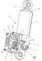
- Fig. 1
- eine perspektivische Schrägansicht eines Ausführungsbeispieles der Erfindung;
- Fig. 2
- einen Längsschnitt des Ausführungsbeispieles;
- Fig. 3
- eine abgebrochene und gegenüber
Fig. 1 und2 leicht vergrößert gezeichnete perspektivische Schrägansicht des Bereichs des Bodenteiles des Ausführungsbeispieles mit durchsichtig gezeichnetem Gehäuse des Anbauteiles; - Fig. 4
- eine Seitenansicht auf den Bereich des Anbauteiles mit geöffnetem Gehäuse, wobei lediglich Schaltventile des hydraulischen Steuerblocks sichtbar sind und die zugehörige hydraulische Schaltung teilweise symbolhaft angedeutet ist;
- Fig. 5
- eine Symboldarstellung der hydraulischen Schaltung;
- Fig. 6
- eine vergrößerte perspektivische Schrägansicht des dem Ausführungsbeispiel zugehörigen Controllers;
- Fig. 7
- eine diagrammartige Darstellung des Beispiels einer entsprechenden Vernetzung mehrerer Arbeitszylinder mit einem CAN-Bus, und
- Fig. 8
- ein weiteres diagrammartig dargestelltes Beispiel der Vernetzung bei Benutzung des erfindungsgemäßen Systems.
- Mit Bezug auf die beigefügte Zeichnung ist die Erfindung beispielhaft anhand eines doppelt wirkenden Arbeitszylinders 1 beschrieben, bei dem zwischen stangenseitigem Arbeitsraum 3 und kolbenseitigem Arbeitsraum 5 eine Fluidverbindung über eine Verbindungsleitung gebildet ist. Derartige Arbeitszylinder 1 sind als Federungszylinder oder für die Positionsregelung einer Last einsetzbar. Bei dem gezeigten Beispiel ist der Arbeitszylinder 1 in Doppelrohrbauweise ausgeführt, bei der die Verbindung zwischen den Arbeitsräumen 3 und 5 in das Zylindergehäuse integriert ist, so dass eine ansonsten zu diesem Zweck vorhandene externe Rohrleitung entfällt, daher keine Probleme bei Steinschlag aufkommen können und die.Gefahr der Bildung von Leckstellen vermieden ist.
- Eine derartige, kompakte Bauform ist in der einen diesbezüglichen, nachveröffentlichten Stand der Technik aufzeigenden Anmeldung
DE 10 2014 007 641.5 offenbart. Der grundsätzliche mechanische Aufbau des vorliegend beschriebenen Zylinders 1 entspricht dieser Bauweise. Dabei ist zur Führung eines Kolbens 7, der mit einer Kolbenstange 9 verbunden ist, ein inneres Zylinderrohr 11 vorgesehen, das sich zwischen einem in der Zeichnung unten liegenden Bodenteil 13 und einem oberen Abschlussteil 15 erstreckt, das den Verschluss des angrenzenden Arbeitsraumes 3 bildet und durch das die Kolbenstange 9 abgedichtet nach außen hindurch geführt ist. Vom Bodenteil 13 ausgehend, ist das innere Zylinderrohr 11 koaxial von einem Außenrohr 17 umgeben, das sich über das obere Ende des inneren Zylinderrohres 11 hinaus erstreckt und mit dem oberen Abschlussteil 15 verschraubt ist. Das Abschlussteil 15 bildet an seinem inneren Endbereich eine Abstützung 19 für das innere Zylinderrohr 11, um dieses am Bodenteil 13 festzulegen. - Der Außendurchmesser des inneren Zylinderrohres 11 ist geringer als der Innendurchmesser des einen koaxialen Außenzylinder bildenden Außenrohres 17, so dass ein sich entlang der Außenseite des inneren Zylinderrohres 11 erstreckender Ringraum 21 gebildet ist. Der Arbeitsraum 3 ist über einen am Abschlussteil 15 gebildeten Spalt 23 mit dem Ringraum 21 in Verbindung, so dass dieser eine interne Verbindungsleitung zum Bodenteil 13 hin bildet. Über in
Fig. 2 nicht sichtbare, im Bodenteil 13 ausgebildete Fluidwege sind das Ende des Ringraums 21 sowie der an das Bodenteil 13 angrenzende Arbeitsraum 5 in Fluidverbindung mit einem hydraulischen Steuerblock 25. Dieser befindet sich, wie unten näher ausgeführt ist, zusammen mit weiteren Komponenten in einem als Anbauteil am Bodenteil 13 festgelegten Gehäuse 27. - In einem an den Kolben 7 anschließenden Längenabschnitt bildet die Kolbenstange 9 ein Hohlrohr, so dass ein sich koaxial erstreckender Hohlraum 29 für eine Sensoreinrichtung in Form eines Weg-Messsystems 31 gebildet ist. Dieses weist einen stangenartigen Hohlkörper 33 auf, der sich vom Bodenteil 13 in den Hohlraum 29 der Kolbenstange 9 erstreckt und ein Schutzrohr für den Wellenleiter einer magnetostriktiv arbeitenden Linearwegsensoreinheit bildet, wie sie von der Anmelderin unter der Bezeichnung HLT1100 vertrieben wird. Als Positionssensor dieses Systems 31 weist der Kolben 7 ein Permanentmagnetelement 35 auf. Das untere Ende des Hohlkörpers 33 ist mittels einer Klemmschraube 37 festgelegt, die in einer ins Innere des Gehäuses 27 mündenden Bohrung 39 sitzt, so dass die Klemmschraube 37 vom Gehäuseinneren her zugänglich ist. Ein Zugang 41 für Leitungen zur Signalübertragung vom Weg-Messsystem 31 mündet ebenfalls ins Innere des Gehäuses 27.
- Das Gehäuse 27 hat im großen Ganzen die Form eines Quaders mit rechteckförmigem Grundriss, siehe insbesondere
Fig. 4 , gebildet aus einer einteiligen Kappe 43, beim gezeigten Beispiel in Form eines Aluminiumteils. Die Kappe 43 ist an den vier Eckbereichen mittels Schrauben 45 in Gewindebohrungen 47 des Bodenteils 13 abnehmbar festgelegt. Mittels einer am Rand umlaufenden Dichtleiste 49 bildet das Gehäuse 27 einen dichten Einschluss für die enthaltenen Komponenten. - Neben dem hydraulischen Steuerblock 25 ist im Gehäuse 27 ein Controller 51 angeordnet, dessen Platine in
Fig. 6 gesondert dargestellt ist. Diese weist Befestigungslöcher 53 für abgedichtete Schraubverbindungen mit der Kappe 43 auf. Der im Gehäuse 27 befindliche hydraulische Steuerblock weist zwei Wege-Schaltventile 57 und 59 in Form von 2/2-Wegeventilen auf, die elektromagnetisch betätigbar sind und deren Spulenanschlüsse mit 61 bzw. 63 bezeichnet (siehe insbesondereFig. 4 ) und mit dem Controller 51 verbunden sind, mit dem auch über den Zugang 41 die Signalanschlüsse des Weg-Messsystems 31 in Verbindung sind. - Wie erwähnt, bildet die Kappe 43 des Gehäuses 27 einen dichten Einschluss für Controller 51 und Wege-Schaltventile 57 und 59, wobei jedoch für elektronische und elektrische Ein- und Ausgänge feuchtigkeitsdichte Durchführungen 67 und 69 in der Kappe 43 vorgesehen sind. Da das Gehäuse 27 mit der am Bodenteil 13 abgedichteten Kappe 43 ein Luftvolumen dicht einschließt, ist in einer Seitenwand der Kappe 43 ein Druckausgleichselement 71 angeordnet, das dem Stand der Technik entspricht und einen gegen Spritzwasser und Strahlwasser geschützten Druckausgleich ermöglicht und Druckanstiege bei Temperaturerhöhungen verhindert.
- Die
Fig. 5 zeigt ein Beispiel der hydraulischen Schaltung des Steuerblocks 25 für eine Auslegung des Arbeitszylinders 1 als Federungszylinder oder zur Positionsregelung einer an der Kolbenstange 9 angreifenden Last, wobei inFig. 5 die interne Verbindung der Arbeitsräume 5 und 3 im Arbeitszylinder 1 nicht dargestellt ist. Die als 2/2-Wegeventile ausgebildeten Schaltventile 57 und 59 sind in einer Grund-Schaltstellung dargestellt. Verbleibt das Ventil 57 in seiner in derFig. 5 gezeigten Stellung, wird von der Pumpenseite P des Versorgungsnetzes unter Druck stehendes Fluid über die Blende 77 sowie über das Rückschlagventil 79 in den stangenseitigen Arbeitsraum 3 gebracht und durch Schalten des Ventils 59 in seine in Blickrichtung auf dieFig. 5 gesehene rechte Schaltdarstellung wird der kolbenseitige Arbeitsraum 5 zur Tankseite T des Versorgungsnetzes hin entlastet. Dies hat zur Folge, dass die Kolbenstange 9 mit Kolben 7 in das Zylindergehäuse des Arbeitszylinders 1 einfährt. - Bleibt das Ventil 59 unbetätigt, also in seiner in
Fig. 5 gezeigten sperrenden Stellung, und wird das Ventil 57 in seine Durchlassstellung gemäß dem rechts dargestellten Schaltsymbol gebracht, gelangt über den Druckversorgungsanschluss P, die Blende 77 sowie die Rückschlagventile 79 und 79' Fluid unter Einbezug des Ventiles 57 in den kolbenseitigen Arbeitsraum 5 des Arbeitszylinders 1 und dieser fährt aus. Das hierbei verdrängte überschüssige Fluid im stangenseitigen Arbeitsraum 3 wird zumindest teilweise über die bereits angesprochene, in derFig. 5 der Einfachheit halber nicht dargestellte interne Verbindung zwischen den Arbeitsräumen 3 und 5 im Arbeitszylinder 1 ausgeglichen. Des Weiteren ist der inFig. 5 dargestellte hydraulische Versorgungskreis über ein Druckbegrenzungsventil 83 abgesichert, das im Bypass eine Ablassschraube 85 aufweist. Wie dieFiguren 1 und4 zeigen, ist die Kombination aus Druckbegrenzungsventil 83 und Ablassschraube 85 als Schraubeinsatz in das Bodenteil 13 eingebaut, in dem sich die Fluidverbindungen mit seitlichem Druckanschluss P und Tankanschluss T befinden. - Die
Figur 7 zeigt ein entsprechendes Beispiel der Vernetzung mehrerer Arbeitszylinder 1 mit einem CAN-Bus 87 als Hauptcontroller. Dabei ist der jeweilige Steuerblock 89 der Arbeitszylinder 1 von diesen räumlich abgesetzt, ebenso wie der jeweils zugeordnete Controller 91, die wiederum mit dem zentralen CAN-Bus 87 in Verbindung sind. Somit sind zusätzlich zur jeweiligen Hydraulikversorgung äußere Verbindungsleitungen 93 zwischen den Controllern 91 und den Steuerblöcken 89 sowie jeweils eine externe Sensorleitung 95 erforderlich, wobei ein an dem CAN-Bus 87 angeschlossener Controller als sogenannte "Master" funktioniert und die Ansteuerung der anderen Controller 91 steuert. - Die
Fig. 8 zeigt einen anderen Verbindungsaufbau bei Benutzung des erfindungsgemäßen hydraulischen Systems mit Smart-Zylindern 97, die außer der hydraulischen Versorgung lediglich eine externe Verbindung 99 mit dem zentralen CAN-Bus 87 oder untereinander benötigen, so dass die Vernetzung mit verringertem Aufwand realisierbar ist. Ähnlich wie die "Einschleifung" des CAN-Bussystems 87 für die einzelnen Smart-Zylinder 97 und deren jeweilige Controller 91 erfolgt, ist dies für das Versorgungsnetz mit der P- und der T-Fluidleitung realisiert, das gegebenenfalls noch um Steuerleitungen ergänzt sein kann, beispielsweise in Form von Load-Sensing-Steuerleitungen. Wie insbesondere dieFig. 7 zeigt, ist dabei einem elektrischen Bussystem vergleichbar jeder hydraulische Steuerblock 89 eines Arbeitszylinders 1 an die Pumpendruck-Versorgungsleitung P ebenso angeschlossen wie an die Tankrücklauf-Leitung T. Dergestalt ist ein modular aufgebautes Bussystem sowohl von der elektronischen als auch von der hydraulischen Ansteuerseite im Abzweig für den jeweils anzuschließenden Verbraucher erreicht. Dies hat so keine Entsprechung im Stand der Technik.
Claims (11)
- Hydraulisches System, bestehend aus mindestens einem hydraulischen Arbeitszylinder (1), einem hydraulischen Steuerblock (25), einem elektronischen Controller (51) und einer Sensoreinrichtung (31), dadurch gekennzeichnet, dass der Steuerblock (25), der Controller (51) und die Sensoreinrichtung (31) als Anbau- bzw. als Einbauteile am Arbeitszylinder (1) festgelegt sind.
- Hydraulisches System nach Anspruch 1, dadurch gekennzeichnet, dass zumindest der Controller (51) und der Steuerblock (25) in einem als Anbauteil am Arbeitszylinder (1) festgelegten Gehäuse (27) eingebaut sind.
- Hydraulisches System nach Anspruch 1 oder 2, dadurch gekennzeichnet, dass die Sensoreinrichtung (31) als Einbauteil in den Arbeitszylinder (1) integriert ist.
- Hydraulisches System nach einem der vorstehenden Ansprüche, dadurch gekennzeichnet, dass eine Sensoreinrichtung in Form eines die Position der Kolben-Stangeneinheit (7, 9) des Arbeitszylinders (1) erkennenden Weg-Messsystems (31) vorgesehen ist.
- Hydraulisches System nach einem der vorstehenden Ansprüche, dadurch gekennzeichnet, dass das Gehäuse (27) einen dichten Einschluss der in ihm befindlichen Komponenten bildet, und dass an einem Gehäuseteil (43) ein Be- und Entlüftungselement (71) angeordnet ist, das einen gegen Flüssigkeitsdurchtritt geschützten Druckausgleich ermöglicht.
- Hydraulisches System nach einem der vorstehenden Ansprüche, dadurch gekennzeichnet, dass der hydraulische Steuerblock (25) elektromagnetisch betätigbare Wege-Schaltventile (57, 59) aufweist.
- Hydraulisches System nach einem der vorstehenden Ansprüche, dadurch gekennzeichnet, dass das Gehäuse (27) feuchtigkeitsdichte Durchführungen (67, 69) für elektrische und/oder elektronische Anschlüsse für die Versorgung der Spulen (61, 63) der Schaltventile (57, 59), des Controllers (51) und der Sensoreinrichtung (31) aufweist.
- Hydraulisches System nach einem der vorstehenden Ansprüche, dadurch gekennzeichnet, dass das Weg-Messsystem (31) einen stangenartigen Hohlkörper (33) aufweist, der am Bodenteil (13) des Arbeitszylinders (1) festgelegt ist und sich axial durch dessen kolbenseitigen Arbeitsraum (5) erstreckt, und dass eine Feststellschraube (37) für den Hohlkörper (33) vom Inneren des Gehäuses (27) her zugänglich ist.
- Hydraulisches System nach einem der vorstehenden Ansprüche, dadurch gekennzeichnet, dass der Hohlkörper (33) als Schutzrohr für den Wellenleiter eines magnetostriktiv arbeitenden Linear-Wegsensorsystems (31) ist, bei dem der Kolben (7) des Arbeitszylinders (1) mit einem permanentmagnetischen Element (35) versehen ist, das den Positionssensor des Systems (31) bildet.
- Hydraulisches System nach einem der vorstehenden Ansprüche, dadurch gekennzeichnet, dass ein Arbeitszylinder in Form eines Federungszylinders (1) vorgesehen ist, bei dem kolbenseitiger Arbeitsraum (5) und stangenseitiger Arbeitsraum (3) über eine Verbindungsleitung (21) miteinander in Fluidverbindung stehen.
- Hydraulisches System nach einem der vorstehenden Ansprüche, dadurch gekennzeichnet, dass der Federungszylinder (1) ein den Kolben (7) führendes inneres Zylinderrohr (11) und ein umgebendes, äußeres Zylinderrohr (17) aufweist, und dass ein zwischen innerem Rohr (11) und äußerem Rohr (17) gebildeter Ringraum (21) einen Großteil der Länge der Verbindungsleitung bildet.
Applications Claiming Priority (1)
| Application Number | Priority Date | Filing Date | Title |
|---|---|---|---|
| DE102014013018.5A DE102014013018A1 (de) | 2014-09-02 | 2014-09-02 | Hydraulisches System |
Publications (2)
| Publication Number | Publication Date |
|---|---|
| EP2993360A1 true EP2993360A1 (de) | 2016-03-09 |
| EP2993360B1 EP2993360B1 (de) | 2022-11-09 |
Family
ID=53871797
Family Applications (1)
| Application Number | Title | Priority Date | Filing Date |
|---|---|---|---|
| EP15002207.7A Active EP2993360B1 (de) | 2014-09-02 | 2015-07-25 | Hydraulisches system |
Country Status (3)
| Country | Link |
|---|---|
| EP (1) | EP2993360B1 (de) |
| DE (1) | DE102014013018A1 (de) |
| PL (1) | PL2993360T3 (de) |
Cited By (1)
| Publication number | Priority date | Publication date | Assignee | Title |
|---|---|---|---|---|
| CN114518066A (zh) * | 2022-04-01 | 2022-05-20 | 北京特倍福电子技术有限公司 | 一种双拉杆式外置磁致伸缩位移传感器 |
Families Citing this family (3)
| Publication number | Priority date | Publication date | Assignee | Title |
|---|---|---|---|---|
| DE102016215071A1 (de) * | 2016-08-12 | 2018-02-15 | Robert Bosch Gmbh | Kraftsensor, insbesondere geeignet für eine elektrohydraulische Hubwerksregelung eines Ackerschleppers |
| DE102019216083B4 (de) * | 2019-10-18 | 2024-11-21 | Hawe Hydraulik Se | Fahrgast-Rückhaltevorrichtung und Fahrgeschäft-Fahrgasteinheit |
| DE102022004564A1 (de) * | 2022-12-06 | 2024-06-06 | Bümach Engineering International B.V. | Verfahren zur Herstellung eines Arbeitszylinders mit einem Positionssensor |
Citations (9)
| Publication number | Priority date | Publication date | Assignee | Title |
|---|---|---|---|---|
| US2761425A (en) * | 1952-06-17 | 1956-09-04 | Gen Motors Corp | Reciprocatory fluid actuated device |
| DE3524414A1 (de) * | 1985-04-16 | 1986-10-23 | GAS Gesellschaft für Antriebs- und Steuerungstechnik mbH & Co KG, 7742 St Georgen | Linearantrieb |
| DE29818075U1 (de) * | 1998-10-09 | 1998-12-24 | Kuhnke GmbH, 23714 Malente | Fluidischer Aktuator |
| EP1217220A2 (de) * | 2000-12-20 | 2002-06-26 | Caterpillar Inc. | Fluidzylinder mit integriertem Positionsensor |
| DE202005006795U1 (de) * | 2005-04-22 | 2005-07-21 | Festo Ag & Co. | Antriebsvorrichtung mit Stellungsregler |
| DE102010054108A1 (de) | 2010-12-10 | 2012-06-14 | Hydac System Gmbh | Ventilanordnung zur Steuerung eines Zusatz-Lenksystems bei mehrachsigen Fahrzeugen, insbesondere Mobilkranen |
| DE102011108874A1 (de) | 2011-07-28 | 2013-01-31 | Hydac System Gmbh | Steuervorrichtung |
| DE102011086108A1 (de) * | 2011-11-10 | 2013-05-16 | Zf Friedrichshafen Ag | Druckausgleichsvorrichtung, Gehäuse und Verfahren zum Herstellen einer Druckausgleichsvorrichtung |
| CA2878141A1 (en) * | 2012-08-13 | 2014-02-20 | Kayaba Industry Co., Ltd. | Actuator |
Family Cites Families (2)
| Publication number | Priority date | Publication date | Assignee | Title |
|---|---|---|---|---|
| DE3430045C2 (de) * | 1984-08-16 | 1986-07-17 | Boge Gmbh, 5208 Eitorf | Vorrichtung zur Wegbestimmung eines Kolbens |
| DE102014007641A1 (de) | 2014-05-22 | 2015-11-26 | Hydac System Gmbh | Federelement |
-
2014
- 2014-09-02 DE DE102014013018.5A patent/DE102014013018A1/de not_active Withdrawn
-
2015
- 2015-07-25 EP EP15002207.7A patent/EP2993360B1/de active Active
- 2015-07-25 PL PL15002207.7T patent/PL2993360T3/pl unknown
Patent Citations (9)
| Publication number | Priority date | Publication date | Assignee | Title |
|---|---|---|---|---|
| US2761425A (en) * | 1952-06-17 | 1956-09-04 | Gen Motors Corp | Reciprocatory fluid actuated device |
| DE3524414A1 (de) * | 1985-04-16 | 1986-10-23 | GAS Gesellschaft für Antriebs- und Steuerungstechnik mbH & Co KG, 7742 St Georgen | Linearantrieb |
| DE29818075U1 (de) * | 1998-10-09 | 1998-12-24 | Kuhnke GmbH, 23714 Malente | Fluidischer Aktuator |
| EP1217220A2 (de) * | 2000-12-20 | 2002-06-26 | Caterpillar Inc. | Fluidzylinder mit integriertem Positionsensor |
| DE202005006795U1 (de) * | 2005-04-22 | 2005-07-21 | Festo Ag & Co. | Antriebsvorrichtung mit Stellungsregler |
| DE102010054108A1 (de) | 2010-12-10 | 2012-06-14 | Hydac System Gmbh | Ventilanordnung zur Steuerung eines Zusatz-Lenksystems bei mehrachsigen Fahrzeugen, insbesondere Mobilkranen |
| DE102011108874A1 (de) | 2011-07-28 | 2013-01-31 | Hydac System Gmbh | Steuervorrichtung |
| DE102011086108A1 (de) * | 2011-11-10 | 2013-05-16 | Zf Friedrichshafen Ag | Druckausgleichsvorrichtung, Gehäuse und Verfahren zum Herstellen einer Druckausgleichsvorrichtung |
| CA2878141A1 (en) * | 2012-08-13 | 2014-02-20 | Kayaba Industry Co., Ltd. | Actuator |
Cited By (1)
| Publication number | Priority date | Publication date | Assignee | Title |
|---|---|---|---|---|
| CN114518066A (zh) * | 2022-04-01 | 2022-05-20 | 北京特倍福电子技术有限公司 | 一种双拉杆式外置磁致伸缩位移传感器 |
Also Published As
| Publication number | Publication date |
|---|---|
| DE102014013018A1 (de) | 2016-03-03 |
| EP2993360B1 (de) | 2022-11-09 |
| PL2993360T3 (pl) | 2023-03-20 |
Similar Documents
| Publication | Publication Date | Title |
|---|---|---|
| EP0854982B1 (de) | Ventilsystem | |
| EP3394454B1 (de) | Ventil, insbesondere 4/2-wegeschieberventil | |
| EP2220380B1 (de) | Hydraulische ventilvorrichtung | |
| EP2993360B1 (de) | Hydraulisches system | |
| DE102004056418A1 (de) | Hydraulische Anordnung | |
| EP3142906A1 (de) | Hydraulikblock für ein hydraulikaggregat einer schlupfregelung einer hydraulischen fahrzeugbremsanlage | |
| EP3781819B1 (de) | Steuervorrichtung | |
| DE202011110940U1 (de) | Kompaktes Zweiwege-Einbauventil mit kombiniertem Flanschdeckel | |
| EP2628959B1 (de) | Servoventil | |
| DE3347000A1 (de) | Elektrohydraulische einrichtung zur steuerung eines doppeltwirkenden hydromotors | |
| EP3058236B1 (de) | Steuervorrichtung | |
| DE60015589T2 (de) | Unterwassersystem mit vorrichtung zur kontrolle eines hydraulischen betätigungswerkzeuges und mit einem solchen werkzeug | |
| DE102008014539A1 (de) | Hydromechanisches System | |
| EP2875268B1 (de) | Hydrauliksystem mit einer druckwaage in form eines ventils, insbesondere eines stetigventils | |
| DE102016106589A1 (de) | Elektrohydraulischer Steuerkreis mit Schrittmotor | |
| DE102010054108A1 (de) | Ventilanordnung zur Steuerung eines Zusatz-Lenksystems bei mehrachsigen Fahrzeugen, insbesondere Mobilkranen | |
| EP2952419B1 (de) | Feder-dämpferelement für die kabinenfederung von fahrzeugen | |
| EP2466154B1 (de) | Elektrohydraulische Steuervorrichtung | |
| DE102015008837A1 (de) | Hydraulikaggregat | |
| DE102016118576B4 (de) | Schaltventileinheit für eine Luftfedereinheit einer Luftfederanlage | |
| EP2220378B1 (de) | Hydraulische ventilvorrichtung | |
| DE102009034286B3 (de) | Hydraulische Schaltungsanordnung zum Steuern eines doppelt wirkenden Arbeitszylinders mittels eine fünf Anschlüsse aufweisenden Steuerventils | |
| DE102004010053A1 (de) | Federungsvorrichtung | |
| EP2761189B1 (de) | Hydraulikzylinder mit ventileinrichtung | |
| DE19724432C1 (de) | Hydraulischer Steuerblock für Teleskopzylinder von Kippfahrzeugen oder ähnlichen Vorrichtungen |
Legal Events
| Date | Code | Title | Description |
|---|---|---|---|
| PUAI | Public reference made under article 153(3) epc to a published international application that has entered the european phase |
Free format text: ORIGINAL CODE: 0009012 |
|
| AK | Designated contracting states |
Kind code of ref document: A1 Designated state(s): AL AT BE BG CH CY CZ DE DK EE ES FI FR GB GR HR HU IE IS IT LI LT LU LV MC MK MT NL NO PL PT RO RS SE SI SK SM TR |
|
| AX | Request for extension of the european patent |
Extension state: BA ME |
|
| 17P | Request for examination filed |
Effective date: 20160310 |
|
| STAA | Information on the status of an ep patent application or granted ep patent |
Free format text: STATUS: EXAMINATION IS IN PROGRESS |
|
| RAP1 | Party data changed (applicant data changed or rights of an application transferred) |
Owner name: HYDAC SYSTEMS & SERVICES GMBH |
|
| 17Q | First examination report despatched |
Effective date: 20180706 |
|
| GRAP | Despatch of communication of intention to grant a patent |
Free format text: ORIGINAL CODE: EPIDOSNIGR1 |
|
| STAA | Information on the status of an ep patent application or granted ep patent |
Free format text: STATUS: GRANT OF PATENT IS INTENDED |
|
| INTG | Intention to grant announced |
Effective date: 20220719 |
|
| GRAS | Grant fee paid |
Free format text: ORIGINAL CODE: EPIDOSNIGR3 |
|
| GRAA | (expected) grant |
Free format text: ORIGINAL CODE: 0009210 |
|
| STAA | Information on the status of an ep patent application or granted ep patent |
Free format text: STATUS: THE PATENT HAS BEEN GRANTED |
|
| AK | Designated contracting states |
Kind code of ref document: B1 Designated state(s): AL AT BE BG CH CY CZ DE DK EE ES FI FR GB GR HR HU IE IS IT LI LT LU LV MC MK MT NL NO PL PT RO RS SE SI SK SM TR |
|
| REG | Reference to a national code |
Ref country code: GB Ref legal event code: FG4D Free format text: NOT ENGLISH |
|
| REG | Reference to a national code |
Ref country code: CH Ref legal event code: EP Ref country code: AT Ref legal event code: REF Ref document number: 1530541 Country of ref document: AT Kind code of ref document: T Effective date: 20221115 |
|
| REG | Reference to a national code |
Ref country code: DE Ref legal event code: R096 Ref document number: 502015016142 Country of ref document: DE |
|
| REG | Reference to a national code |
Ref country code: IE Ref legal event code: FG4D Free format text: LANGUAGE OF EP DOCUMENT: GERMAN |
|
| REG | Reference to a national code |
Ref country code: NL Ref legal event code: FP |
|
| REG | Reference to a national code |
Ref country code: LT Ref legal event code: MG9D |
|
| PG25 | Lapsed in a contracting state [announced via postgrant information from national office to epo] |
Ref country code: SE Free format text: LAPSE BECAUSE OF FAILURE TO SUBMIT A TRANSLATION OF THE DESCRIPTION OR TO PAY THE FEE WITHIN THE PRESCRIBED TIME-LIMIT Effective date: 20221109 Ref country code: PT Free format text: LAPSE BECAUSE OF FAILURE TO SUBMIT A TRANSLATION OF THE DESCRIPTION OR TO PAY THE FEE WITHIN THE PRESCRIBED TIME-LIMIT Effective date: 20230309 Ref country code: NO Free format text: LAPSE BECAUSE OF FAILURE TO SUBMIT A TRANSLATION OF THE DESCRIPTION OR TO PAY THE FEE WITHIN THE PRESCRIBED TIME-LIMIT Effective date: 20230209 Ref country code: LT Free format text: LAPSE BECAUSE OF FAILURE TO SUBMIT A TRANSLATION OF THE DESCRIPTION OR TO PAY THE FEE WITHIN THE PRESCRIBED TIME-LIMIT Effective date: 20221109 Ref country code: FI Free format text: LAPSE BECAUSE OF FAILURE TO SUBMIT A TRANSLATION OF THE DESCRIPTION OR TO PAY THE FEE WITHIN THE PRESCRIBED TIME-LIMIT Effective date: 20221109 Ref country code: ES Free format text: LAPSE BECAUSE OF FAILURE TO SUBMIT A TRANSLATION OF THE DESCRIPTION OR TO PAY THE FEE WITHIN THE PRESCRIBED TIME-LIMIT Effective date: 20221109 |
|
| PG25 | Lapsed in a contracting state [announced via postgrant information from national office to epo] |
Ref country code: RS Free format text: LAPSE BECAUSE OF FAILURE TO SUBMIT A TRANSLATION OF THE DESCRIPTION OR TO PAY THE FEE WITHIN THE PRESCRIBED TIME-LIMIT Effective date: 20221109 Ref country code: LV Free format text: LAPSE BECAUSE OF FAILURE TO SUBMIT A TRANSLATION OF THE DESCRIPTION OR TO PAY THE FEE WITHIN THE PRESCRIBED TIME-LIMIT Effective date: 20221109 Ref country code: IS Free format text: LAPSE BECAUSE OF FAILURE TO SUBMIT A TRANSLATION OF THE DESCRIPTION OR TO PAY THE FEE WITHIN THE PRESCRIBED TIME-LIMIT Effective date: 20230309 Ref country code: HR Free format text: LAPSE BECAUSE OF FAILURE TO SUBMIT A TRANSLATION OF THE DESCRIPTION OR TO PAY THE FEE WITHIN THE PRESCRIBED TIME-LIMIT Effective date: 20221109 Ref country code: GR Free format text: LAPSE BECAUSE OF FAILURE TO SUBMIT A TRANSLATION OF THE DESCRIPTION OR TO PAY THE FEE WITHIN THE PRESCRIBED TIME-LIMIT Effective date: 20230210 |
|
| PG25 | Lapsed in a contracting state [announced via postgrant information from national office to epo] |
Ref country code: SM Free format text: LAPSE BECAUSE OF FAILURE TO SUBMIT A TRANSLATION OF THE DESCRIPTION OR TO PAY THE FEE WITHIN THE PRESCRIBED TIME-LIMIT Effective date: 20221109 Ref country code: RO Free format text: LAPSE BECAUSE OF FAILURE TO SUBMIT A TRANSLATION OF THE DESCRIPTION OR TO PAY THE FEE WITHIN THE PRESCRIBED TIME-LIMIT Effective date: 20221109 Ref country code: EE Free format text: LAPSE BECAUSE OF FAILURE TO SUBMIT A TRANSLATION OF THE DESCRIPTION OR TO PAY THE FEE WITHIN THE PRESCRIBED TIME-LIMIT Effective date: 20221109 Ref country code: DK Free format text: LAPSE BECAUSE OF FAILURE TO SUBMIT A TRANSLATION OF THE DESCRIPTION OR TO PAY THE FEE WITHIN THE PRESCRIBED TIME-LIMIT Effective date: 20221109 Ref country code: CZ Free format text: LAPSE BECAUSE OF FAILURE TO SUBMIT A TRANSLATION OF THE DESCRIPTION OR TO PAY THE FEE WITHIN THE PRESCRIBED TIME-LIMIT Effective date: 20221109 |
|
| REG | Reference to a national code |
Ref country code: DE Ref legal event code: R097 Ref document number: 502015016142 Country of ref document: DE |
|
| PG25 | Lapsed in a contracting state [announced via postgrant information from national office to epo] |
Ref country code: SK Free format text: LAPSE BECAUSE OF FAILURE TO SUBMIT A TRANSLATION OF THE DESCRIPTION OR TO PAY THE FEE WITHIN THE PRESCRIBED TIME-LIMIT Effective date: 20221109 Ref country code: AL Free format text: LAPSE BECAUSE OF FAILURE TO SUBMIT A TRANSLATION OF THE DESCRIPTION OR TO PAY THE FEE WITHIN THE PRESCRIBED TIME-LIMIT Effective date: 20221109 |
|
| PLBE | No opposition filed within time limit |
Free format text: ORIGINAL CODE: 0009261 |
|
| STAA | Information on the status of an ep patent application or granted ep patent |
Free format text: STATUS: NO OPPOSITION FILED WITHIN TIME LIMIT |
|
| 26N | No opposition filed |
Effective date: 20230810 |
|
| PG25 | Lapsed in a contracting state [announced via postgrant information from national office to epo] |
Ref country code: SI Free format text: LAPSE BECAUSE OF FAILURE TO SUBMIT A TRANSLATION OF THE DESCRIPTION OR TO PAY THE FEE WITHIN THE PRESCRIBED TIME-LIMIT Effective date: 20221109 |
|
| PG25 | Lapsed in a contracting state [announced via postgrant information from national office to epo] |
Ref country code: MC Free format text: LAPSE BECAUSE OF FAILURE TO SUBMIT A TRANSLATION OF THE DESCRIPTION OR TO PAY THE FEE WITHIN THE PRESCRIBED TIME-LIMIT Effective date: 20221109 |
|
| PG25 | Lapsed in a contracting state [announced via postgrant information from national office to epo] |
Ref country code: MC Free format text: LAPSE BECAUSE OF FAILURE TO SUBMIT A TRANSLATION OF THE DESCRIPTION OR TO PAY THE FEE WITHIN THE PRESCRIBED TIME-LIMIT Effective date: 20221109 |
|
| REG | Reference to a national code |
Ref country code: CH Ref legal event code: PL |
|
| REG | Reference to a national code |
Ref country code: BE Ref legal event code: MM Effective date: 20230731 |
|
| PG25 | Lapsed in a contracting state [announced via postgrant information from national office to epo] |
Ref country code: LU Free format text: LAPSE BECAUSE OF NON-PAYMENT OF DUE FEES Effective date: 20230725 |
|
| PG25 | Lapsed in a contracting state [announced via postgrant information from national office to epo] |
Ref country code: LU Free format text: LAPSE BECAUSE OF NON-PAYMENT OF DUE FEES Effective date: 20230725 |
|
| REG | Reference to a national code |
Ref country code: IE Ref legal event code: MM4A |
|
| PG25 | Lapsed in a contracting state [announced via postgrant information from national office to epo] |
Ref country code: CH Free format text: LAPSE BECAUSE OF NON-PAYMENT OF DUE FEES Effective date: 20230731 |
|
| PG25 | Lapsed in a contracting state [announced via postgrant information from national office to epo] |
Ref country code: BE Free format text: LAPSE BECAUSE OF NON-PAYMENT OF DUE FEES Effective date: 20230731 |
|
| PG25 | Lapsed in a contracting state [announced via postgrant information from national office to epo] |
Ref country code: IE Free format text: LAPSE BECAUSE OF NON-PAYMENT OF DUE FEES Effective date: 20230725 |
|
| PG25 | Lapsed in a contracting state [announced via postgrant information from national office to epo] |
Ref country code: IE Free format text: LAPSE BECAUSE OF NON-PAYMENT OF DUE FEES Effective date: 20230725 |
|
| PG25 | Lapsed in a contracting state [announced via postgrant information from national office to epo] |
Ref country code: BG Free format text: LAPSE BECAUSE OF FAILURE TO SUBMIT A TRANSLATION OF THE DESCRIPTION OR TO PAY THE FEE WITHIN THE PRESCRIBED TIME-LIMIT Effective date: 20221109 |
|
| PG25 | Lapsed in a contracting state [announced via postgrant information from national office to epo] |
Ref country code: BG Free format text: LAPSE BECAUSE OF FAILURE TO SUBMIT A TRANSLATION OF THE DESCRIPTION OR TO PAY THE FEE WITHIN THE PRESCRIBED TIME-LIMIT Effective date: 20221109 |
|
| PGFP | Annual fee paid to national office [announced via postgrant information from national office to epo] |
Ref country code: PL Payment date: 20250506 Year of fee payment: 11 |
|
| PGFP | Annual fee paid to national office [announced via postgrant information from national office to epo] |
Ref country code: GB Payment date: 20250509 Year of fee payment: 11 |
|
| PGFP | Annual fee paid to national office [announced via postgrant information from national office to epo] |
Ref country code: FR Payment date: 20250610 Year of fee payment: 11 |
|
| PG25 | Lapsed in a contracting state [announced via postgrant information from national office to epo] |
Ref country code: CY Free format text: LAPSE BECAUSE OF FAILURE TO SUBMIT A TRANSLATION OF THE DESCRIPTION OR TO PAY THE FEE WITHIN THE PRESCRIBED TIME-LIMIT; INVALID AB INITIO Effective date: 20150725 |
|
| PG25 | Lapsed in a contracting state [announced via postgrant information from national office to epo] |
Ref country code: HU Free format text: LAPSE BECAUSE OF FAILURE TO SUBMIT A TRANSLATION OF THE DESCRIPTION OR TO PAY THE FEE WITHIN THE PRESCRIBED TIME-LIMIT; INVALID AB INITIO Effective date: 20150725 |
|
| PGFP | Annual fee paid to national office [announced via postgrant information from national office to epo] |
Ref country code: NL Payment date: 20250724 Year of fee payment: 11 |
|
| PGFP | Annual fee paid to national office [announced via postgrant information from national office to epo] |
Ref country code: DE Payment date: 20250731 Year of fee payment: 11 |
|
| PGFP | Annual fee paid to national office [announced via postgrant information from national office to epo] |
Ref country code: IT Payment date: 20250704 Year of fee payment: 11 |
|
| PGFP | Annual fee paid to national office [announced via postgrant information from national office to epo] |
Ref country code: AT Payment date: 20250715 Year of fee payment: 11 |
|
| PG25 | Lapsed in a contracting state [announced via postgrant information from national office to epo] |
Ref country code: TR Free format text: LAPSE BECAUSE OF FAILURE TO SUBMIT A TRANSLATION OF THE DESCRIPTION OR TO PAY THE FEE WITHIN THE PRESCRIBED TIME-LIMIT Effective date: 20221109 |