EP2993246A1 - Flat steel wire - Google Patents
Flat steel wire Download PDFInfo
- Publication number
- EP2993246A1 EP2993246A1 EP14791514.4A EP14791514A EP2993246A1 EP 2993246 A1 EP2993246 A1 EP 2993246A1 EP 14791514 A EP14791514 A EP 14791514A EP 2993246 A1 EP2993246 A1 EP 2993246A1
- Authority
- EP
- European Patent Office
- Prior art keywords
- steel wire
- flat steel
- cross
- section
- mpa
- Prior art date
- Legal status (The legal status is an assumption and is not a legal conclusion. Google has not performed a legal analysis and makes no representation as to the accuracy of the status listed.)
- Granted
Links
Images

Classifications
-
- C—CHEMISTRY; METALLURGY
- C22—METALLURGY; FERROUS OR NON-FERROUS ALLOYS; TREATMENT OF ALLOYS OR NON-FERROUS METALS
- C22C—ALLOYS
- C22C38/00—Ferrous alloys, e.g. steel alloys
- C22C38/18—Ferrous alloys, e.g. steel alloys containing chromium
- C22C38/40—Ferrous alloys, e.g. steel alloys containing chromium with nickel
- C22C38/54—Ferrous alloys, e.g. steel alloys containing chromium with nickel with boron
-
- C—CHEMISTRY; METALLURGY
- C21—METALLURGY OF IRON
- C21D—MODIFYING THE PHYSICAL STRUCTURE OF FERROUS METALS; GENERAL DEVICES FOR HEAT TREATMENT OF FERROUS OR NON-FERROUS METALS OR ALLOYS; MAKING METAL MALLEABLE, e.g. BY DECARBURISATION OR TEMPERING
- C21D9/00—Heat treatment, e.g. annealing, hardening, quenching or tempering, adapted for particular articles; Furnaces therefor
- C21D9/52—Heat treatment, e.g. annealing, hardening, quenching or tempering, adapted for particular articles; Furnaces therefor for wires; for strips ; for rods of unlimited length
- C21D9/525—Heat treatment, e.g. annealing, hardening, quenching or tempering, adapted for particular articles; Furnaces therefor for wires; for strips ; for rods of unlimited length for wire, for rods
-
- C—CHEMISTRY; METALLURGY
- C22—METALLURGY; FERROUS OR NON-FERROUS ALLOYS; TREATMENT OF ALLOYS OR NON-FERROUS METALS
- C22C—ALLOYS
- C22C38/00—Ferrous alloys, e.g. steel alloys
- C22C38/001—Ferrous alloys, e.g. steel alloys containing N
-
- C—CHEMISTRY; METALLURGY
- C22—METALLURGY; FERROUS OR NON-FERROUS ALLOYS; TREATMENT OF ALLOYS OR NON-FERROUS METALS
- C22C—ALLOYS
- C22C38/00—Ferrous alloys, e.g. steel alloys
- C22C38/002—Ferrous alloys, e.g. steel alloys containing In, Mg, or other elements not provided for in one single group C22C38/001 - C22C38/60
-
- C—CHEMISTRY; METALLURGY
- C22—METALLURGY; FERROUS OR NON-FERROUS ALLOYS; TREATMENT OF ALLOYS OR NON-FERROUS METALS
- C22C—ALLOYS
- C22C38/00—Ferrous alloys, e.g. steel alloys
- C22C38/02—Ferrous alloys, e.g. steel alloys containing silicon
-
- C—CHEMISTRY; METALLURGY
- C22—METALLURGY; FERROUS OR NON-FERROUS ALLOYS; TREATMENT OF ALLOYS OR NON-FERROUS METALS
- C22C—ALLOYS
- C22C38/00—Ferrous alloys, e.g. steel alloys
- C22C38/04—Ferrous alloys, e.g. steel alloys containing manganese
-
- C—CHEMISTRY; METALLURGY
- C22—METALLURGY; FERROUS OR NON-FERROUS ALLOYS; TREATMENT OF ALLOYS OR NON-FERROUS METALS
- C22C—ALLOYS
- C22C38/00—Ferrous alloys, e.g. steel alloys
- C22C38/06—Ferrous alloys, e.g. steel alloys containing aluminium
-
- C—CHEMISTRY; METALLURGY
- C22—METALLURGY; FERROUS OR NON-FERROUS ALLOYS; TREATMENT OF ALLOYS OR NON-FERROUS METALS
- C22C—ALLOYS
- C22C38/00—Ferrous alloys, e.g. steel alloys
- C22C38/12—Ferrous alloys, e.g. steel alloys containing tungsten, tantalum, molybdenum, vanadium, or niobium
-
- C—CHEMISTRY; METALLURGY
- C22—METALLURGY; FERROUS OR NON-FERROUS ALLOYS; TREATMENT OF ALLOYS OR NON-FERROUS METALS
- C22C—ALLOYS
- C22C38/00—Ferrous alloys, e.g. steel alloys
- C22C38/14—Ferrous alloys, e.g. steel alloys containing titanium or zirconium
-
- C—CHEMISTRY; METALLURGY
- C22—METALLURGY; FERROUS OR NON-FERROUS ALLOYS; TREATMENT OF ALLOYS OR NON-FERROUS METALS
- C22C—ALLOYS
- C22C38/00—Ferrous alloys, e.g. steel alloys
- C22C38/16—Ferrous alloys, e.g. steel alloys containing copper
-
- C—CHEMISTRY; METALLURGY
- C22—METALLURGY; FERROUS OR NON-FERROUS ALLOYS; TREATMENT OF ALLOYS OR NON-FERROUS METALS
- C22C—ALLOYS
- C22C38/00—Ferrous alloys, e.g. steel alloys
- C22C38/18—Ferrous alloys, e.g. steel alloys containing chromium
-
- C—CHEMISTRY; METALLURGY
- C22—METALLURGY; FERROUS OR NON-FERROUS ALLOYS; TREATMENT OF ALLOYS OR NON-FERROUS METALS
- C22C—ALLOYS
- C22C38/00—Ferrous alloys, e.g. steel alloys
- C22C38/18—Ferrous alloys, e.g. steel alloys containing chromium
- C22C38/20—Ferrous alloys, e.g. steel alloys containing chromium with copper
-
- C—CHEMISTRY; METALLURGY
- C22—METALLURGY; FERROUS OR NON-FERROUS ALLOYS; TREATMENT OF ALLOYS OR NON-FERROUS METALS
- C22C—ALLOYS
- C22C38/00—Ferrous alloys, e.g. steel alloys
- C22C38/18—Ferrous alloys, e.g. steel alloys containing chromium
- C22C38/24—Ferrous alloys, e.g. steel alloys containing chromium with vanadium
-
- C—CHEMISTRY; METALLURGY
- C22—METALLURGY; FERROUS OR NON-FERROUS ALLOYS; TREATMENT OF ALLOYS OR NON-FERROUS METALS
- C22C—ALLOYS
- C22C38/00—Ferrous alloys, e.g. steel alloys
- C22C38/18—Ferrous alloys, e.g. steel alloys containing chromium
- C22C38/28—Ferrous alloys, e.g. steel alloys containing chromium with titanium or zirconium
-
- C—CHEMISTRY; METALLURGY
- C22—METALLURGY; FERROUS OR NON-FERROUS ALLOYS; TREATMENT OF ALLOYS OR NON-FERROUS METALS
- C22C—ALLOYS
- C22C38/00—Ferrous alloys, e.g. steel alloys
- C22C38/18—Ferrous alloys, e.g. steel alloys containing chromium
- C22C38/32—Ferrous alloys, e.g. steel alloys containing chromium with boron
-
- D—TEXTILES; PAPER
- D07—ROPES; CABLES OTHER THAN ELECTRIC
- D07B—ROPES OR CABLES IN GENERAL
- D07B1/00—Constructional features of ropes or cables
- D07B1/06—Ropes or cables built-up from metal wires, e.g. of section wires around a hemp core
- D07B1/0606—Reinforcing cords for rubber or plastic articles
- D07B1/066—Reinforcing cords for rubber or plastic articles the wires being made from special alloy or special steel composition
-
- C—CHEMISTRY; METALLURGY
- C21—METALLURGY OF IRON
- C21D—MODIFYING THE PHYSICAL STRUCTURE OF FERROUS METALS; GENERAL DEVICES FOR HEAT TREATMENT OF FERROUS OR NON-FERROUS METALS OR ALLOYS; MAKING METAL MALLEABLE, e.g. BY DECARBURISATION OR TEMPERING
- C21D2211/00—Microstructure comprising significant phases
- C21D2211/009—Pearlite
-
- D—TEXTILES; PAPER
- D07—ROPES; CABLES OTHER THAN ELECTRIC
- D07B—ROPES OR CABLES IN GENERAL
- D07B2201/00—Ropes or cables
- D07B2201/20—Rope or cable components
- D07B2201/2001—Wires or filaments
- D07B2201/2002—Wires or filaments characterised by their cross-sectional shape
- D07B2201/2003—Wires or filaments characterised by their cross-sectional shape flat
Definitions
- the present invention relates to a flat steel wire having high strength and excellent secondary workability, the flat steel wire being utilized for improving the pressure resistance and the tensile strength of electrical cables, communication cables, pipes, hoses, or the like.
- Patent Document 1 discloses a high strength flat steel wire including the carbon of 0.90 mass% or more.
- the flat steel wire shows the high strength such as the tensile strength in the longitudinal direction is approximately 200 kgf/mm 2 .
- the secondary workability of the flat steel wire generally decreases with an increase in the strength of the flat steel wire.
- the workability already reaches critical limit, and thus, it may be difficult to subject the flat steel wire to the secondary working such as bending and twisting.
- the flat steel wire is mainly utilized for reinforcing flexible pipes or the like.
- the flexible pipes are utilized for drawing crude oil from offshore oil field, and are required to have high pressure resistance and high tensile strength.
- the flat steel wire is required to have high strength.
- the flat steel wire is utilized by being deformed in a spiral shape for the flexible pipes.
- the flat steel wire is required to have excellent secondary workability against the twisting or the like.
- cracks may initiate from a periphery and may propagate resulting in the longitudinal cracks during being deformed in the spiral shape.
- the flat steel wire is excellent in the strength and the secondary workability, it is possible to actualize the flexible pipes having high pressure resistance and high tensile strength.
- Patent Document 1 Japanese Patent (Granted) Publication No. 3298688
- the present invention is to provide the flat steel wire having high strength and excellent secondary workability.
- the strength indicates the yield strength by tensile test, the 0.2% proof stress by tensile test, the ultimate strength by tensile test, or the like.
- the secondary workability indicates the twisting properties, the total tensile elongation, or the like.
- An aspect of the present invention employs the following.
- the shape of the flat steel wire or the like is preferably controlled, and thus, it is possible to suppress the initiation of cracks from the periphery of the flat steel wire and the propagation of cracks resulting in the longitudinal cracks of the flat steel wire during being twisted or the like. As a result, it is possible to provide the flat steel wire having high strength and excellent secondary workability as compared with the high strength flat steel wire in the related art.
- the limitation range as described below includes a lower limit and an upper limit thereof.
- the present inventors have found that the twisting properties of flat steel wire are capable of being improved by controlling a cross section to be a rectangular shape with rounded corners and by controlling a ratio of a long side of the cross section to a short side of the cross section (long side / short side) to be more than 4 to 8, when the cross section perpendicular to a longitudinal direction is viewed. It seems that, since the cracks from the periphery of the flat steel wire, especially the cracks from the corners, are suppressed and the non-uniform deformation is suppressed, the twisting properties are improved.
- the present inventors have found that the twisting properties of flat steel wire are capable of being preferably improved by controlling residual stress in a surface layer of the flat steel wire to be under compressive stress states. It seems that, since the area where the residual stress in the surface layer of the flat steel wire is under tensile stress states may act as the fracture origin, the twisting properties are preferably improved by reducing the area under the tensile stress states in the surface layer.
- the present inventors have found that the twisting properties of flat steel wire are capable of being further preferably improved by controlling the C content to be 1.00% or less in mass% or by including the alloying elements fixing N as chemical composition of the flat steel wire. It seems that, since the pearlitic structure which is uniform and fine is formed by controlling the C content even under the heat treatment conditions which are industrially applicable, the twisting properties are further preferably improved. Moreover, it seems that, since age hardening of the flat steel wire is suppressed by fixing N in the steel and thereby the non-uniform deformation caused by the local hardening in the flat steel wire is suppressed, the twisting properties are further preferably improved.
- the flat steel wire according to the embodiment shows high strength such that the yield strength or the 0.2% proof stress obtained by tensile test is 1600 MPa or more and the ultimate tensile strength (tensile strength) obtained by the tensile test is 1900 MPa or more, and shows excellent secondary workability such that the total elongation obtained by the tensile test is 2% or more and the twisting value obtained by twist test is 12 times or more.
- the structural steel having the tensile strength of 1000 MPa or more is regarded as being high strength.
- the round steel wire having the twisting value of 12 times or more is regarded as being excellent in the twisting properties. Therefore, it can be said that the flat steel wire according to the embodiment concurrently satisfies the two contrary properties which are the strength and the secondary workability. For example, by using the flat steel wire according to the embodiment, it is possible to actualize the flexible pipes having high pressure resistance and high tensile strength.
- the flat steel wire according to the embodiment has the rectangular shape with rounded corners when the cross section perpendicular to the longitudinal direction is viewed, wherein: the short side of the cross section is 2 mm to 7 mm; the long side of the cross section is longer than 8 mm to 56 mm; and the ratio of the long side to the short side is more than 4 to 8.
- the shorter line (short side) is referred to as "thickness” and the longer line (long side) is referred to as "width” in the flat steel wire.
- the shorter side in the cross section which is the rectangular shape with rounded corners is regarded as the short side (thickness).
- the length of the short side is defined as the length from a corner to a corner when the corners of the cross section are presumed to be the substantially right angles without rotundity.
- the longer side in the cross section which is the rectangular shape with rounded corners is regarded as the long side (width).
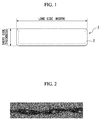
- Fig. 1 schematically shows the short side (thickness) and the long side (width) in the cross section of the flat steel wire 1 according to the embodiment.
- the flat steel wire 1 has the rectangular shape, and each corner has arc shape, when the cross section perpendicular to the longitudinal direction is viewed.
- the cross-sectional shape is the rectangular shape with rounded corners where each corner is roundish. Since the cross-sectional shape is the rectangular shape with rounded corners, the fracture such that the corners act as the fracture origin is suppressed at the secondary working. In addition, since the cross-sectional shape is the rectangular shape with rounded corners, the interference in each corner of adjacent flat steel wires 1 is suppressed when the flat steel wire 1 is deformed in the spiral shape to the pipe.
- an upper limit of the thickness of the flat steel wire 1 is to be 7 mm.
- the thickness of the flat steel wire 1 is to be 2 mm or longer.
- the thickness of the flat steel wire 1 is to be 2 mm to 7 mm.
- the ratio of width to thickness is to be more than 4 to 8.
- the ratio of long side to short side is 8 or less, the non-uniform deformation is suppressed, and thereby, the twisting properties are improved.
- carbon and alloying elements need to be included more than necessary to ensure the strength, and as a result, the ductility and the secondary workability of the flat steel wire 1 decrease.
- the width (long side) of the flat steel wire 1 may be longer than 8 mm to 56 mm.
- the short side of the cross section is 2 mm to 6 mm and the long side of the cross section is longer than 8 mm to 48 mm, and it is more preferable that the short side of the cross section is 2 mm to 5 mm and the long side of the cross section is longer than 8 mm to 40 mm.
- a lower limit of the ratio of width to thickness is 5 or more and an upper limit of the ratio of width to thickness is 7 or less.
- the tensile strength is 1900 MPa or more.
- an upper limit of the tensile strength is not particularly limited, the upper limit may be 2400 MPa.
- the total elongation is to be 2% or more to ensure the ductility.
- an upper limit of the total elongation is not particularly limited, the upper limit may be 5%.
- the yield strength or the 0.2% proof stress is to be 1600 MPa or more.
- an upper limit of the yield strength or the 0.2% proof stress is not particularly limited, the upper limit may be 2000 MPa. It is preferable that the yield strength or the 0.2% proof stress is less than the tensile strength. Specifically, it is preferable that the ration of the yield strength or the 0.2% proof stress to the tensile strength (the yield strength or the 0.2% proof stress / the tensile strength) is 0.8 to 0.95.
- the above mechanical properties may be controlled by the production conditions such as rolling conditions.
- the above mechanical properties may be controlled by controlling the rod diameter of steel wire rod before the rolling and by controlling the rolling temperature and the rolling reduction at the rolling.
- the above mechanical properties may be controlled by controlling the chemical composition of the flat steel wire 1.
- the flat steel wire 1 according to the embodiment shows excellent secondary workability. Specifically, it is possible to conduct the twisting of 12 times or more by the twist test under the condition of chuck distance of 500 mm. In this manner, in the flat steel wire 1 according to the embodiment, the strength and the secondary workability are concurrently excellent.
- Fig. 2 shows the flat steel wire 1 according to the embodiment after being twisted. As shown in Fig. 2 , the flat steel wire 1 according to the embodiment is excellent in the twisting properties in addition to high strength.
- an upper limit of the twisting value is not particularly limited, the upper limit may be 25 times.
- the residual stress having positive value is regarded as the tensile residual stress
- the residual stress having negative value is regarded as the compressive residual stress
- the twisting properties of the flat steel wire 1 are preferably improved.
- the surface layer 2 of the flat steel wire 1 is the area within 1 ⁇ m in depth from the contour line of the cross section toward the centroid of the cross section in case that the cross section perpendicular to the longitudinal direction is viewed
- the average residual stress in the longitudinal direction may be -200 MPa or less in the surface layer 2.
- the twisting properties of the flat steel wire 1 are preferably improved.
- the average residual stress of -200 MPa or less expresses that the average residual stress is, for example, -220 MPa, -250 MPa, or the like.
- a lower limit of the average residual stress is not particularly limited, the lower limit may be -1200 MPa.
- the average residual stress is -1200 MPa to -200 MPa. Even when the residual stress of the local area in the surface layer 2 of the flat steel wire 1 is under tensile stress states, it is possible to preferably obtain the above effect when the average residual stress in the surface layer 2 of the flat steel wire 1 is under compressive stress states and -200 MPa or less.
- Fig. 1 schematically shows the surface layer 2 when the cross section perpendicular to the longitudinal direction is viewed.
- Fig. 3 shows the relationship between the average residual stress in the surface layer 2 and the twisting value obtained by the twist test. As shown in Fig. 3 , the twisting properties of the flat steel wire 1 are critically improved when the average compressive residual stress in the surface layer 2 is -200 MPa or less.
- the average compressive residual stress in the surface layer 2 is -200 MPa or less.
- the average compressive residual stress in the surface layer 2 is -300 MPa or less or -400 MPa or less.
- the surface layer 2 of the flat steel wire 1 is the area within 2 ⁇ m or 3 ⁇ m in depth toward the above centroid.
- the flat steel wire 1 includes, as the chemical composition, by mass %, 0.85% to 1.00% of C, 0.80% to 1.30% of Si, 0.30% to 0.90% of Mn, 0.017% or less of P, 0.010% or less of S, 0.20% or less of Cu, 0% to 0.10% of Al, 0% to 0.05% of Ti, 0% to 0.0040% of B, 0% to 0.0060% of N, 0% to 0.5% of Cr, 0% to 0.50% of V, and a balance consisting of Fe and impurities.
- C, Si, and Mn are base elements.
- C (carbon) is an element which increases the cementite fraction in pearlitic steel, and thereby, increases the strength of the pearlitic steel. In general, it is possible to improve the strength of the pearlitic steel by work hardening or by controlling the lamellar spacing of perlite under the optimum production conditions for the patenting or the like.
- the C content is 0.85% or more, it is possible to preferably control the tensile strength to be 1900 MPa or more in addition to ensuring the ductility. Thus, a lower limit of the C content may be 0.85%.
- the C content is 1.00% or less, it is possible to preferably suppress the local segregation, and thereby, suppress the cracks during the deforming.
- an upper limit of the C content may be 1.00%.
- Si is a deoxidizing element for steelmaking and is an element which is effective in solid solution strengthening for ferrite.
- a lower limit of the Si content may be 0.80%.
- an upper limit of the Si content may be 1.30%.
- Mn manganese
- Mn manganese
- a lower limit of the Mn content may be 0.30%.
- an upper limit of the Mn content may be 0.90%.
- the flat steel wire 1 includes, as the chemical composition, the impurities.
- impurities represent elements which are contaminated during industrial production of the steel from ores and scarp that are used as a raw material of the steel, or from environment of a production process.
- P, S, and Cu are limited to the following in order to sufficiently obtain the above mentioned effects.
- the amount of respective impurities is low, a lower limit does not need to be limited, and the lower limit of the respective impurities may be 0%.
- P (phosphorus) is an impurity
- the P content is 0.017% or less, it is possible to preferably suppress the steel embrittlement and the cracks during the deforming of the flat steel wire 1.
- the P content may be limited to 0.017% or less.
- S sulfur
- S is an impurity. S bonds to Mn and forms MnS in the steel. Also, S segregates at the center of steel piece in the steel making and solidification and forms excessive MnS in the center. Thereby, the steel is embrittled.
- the S content is 0.010% or less, it is possible to preferably suppress the fracture which is initiated at the center of the flat steel wire 1. Thus, the S content may be limited to 0.010% or less.
- Cu is an impurity which is mainly contaminated from the scarp or the like. Cu is effective in solid solution strengthening for the steel. However, when the Cu content is 0.20% or less, it is possible to preferably suppress a large decrease in the workability of the flat steel wire 1. Thus, the Cu content may be limited to 0.20% or less.
- the chemical composition of the flat steel wire 1 according to the embodiment includes the above mentioned base elements and the balance consists of Fe and the above mentioned impurities.
- the flat steel wire 1 according to the embodiment may further include the optional element such as Al, Ti, B, N, Cr, and V in substitution for a part of Fe which is the balance.
- the optional elements may be included as necessary.
- a lower limit of the respective optional elements does not need to be limited, and the lower limit may be 0%.
- the optional elements may be included as impurities, the above mentioned effects are not affected.
- A1 (aluminum) is a deoxidizing element for steelmaking and is an element which bonds to N and forms the compounds in the steel. Since A1 fixes N in the steel, it is possible to suppress the age hardening of the flat steel wire 1. Moreover, when Al and B are simultaneously included, since Al fixes N in the steel, the amount of solid-soluted B increases in the steel. Thus, as necessary, the A1 content may be 0% to 0.10%. A preferable lower limit of the A1 content may be 0.005%. When the A1 content is 0.10% or less, it is possible to preferably suppress the formation of Al 2 O 3 cluster, and thereby, suppress the cracks during the deforming.
- Ti Since Ti has the same effect as Al, it is possible to decrease the A1 content depending on the Ti content. In the case, it is possible to obtain the same effect.
- Ti titanium
- Ti titanium
- the Ti content may be 0% to 0.05%.
- a preferable lower limit of the Ti content may be 0.003%.
- B is an element which is solid-soluted in austenite and improves the hardenability.
- the B content may be 0% to 0.0040%.
- a preferable lower limit of the B content may be 0.0005%.
- the B content is 0.0040% or less, it is possible to preferably suppress the formation of Fe 23 (C, B) 6 precipitates or the like, and thereby, suppress the cracks during the deforming.
- N nitrogen
- the N content may be 0% to 0.0060%.
- a preferable lower limit of the N content may be 0.0015%.
- the N content is 0.0060% or less, it is possible to preferably suppress the age hardening caused by the excessive free N which does not bond to Al, Ti, or B, and thereby, suppress a decrease in the ductility of the flat steel wire 1.
- Cr chromium
- Cr is an element which decreases the lamellar spacing of perlite, and thereby, improves the strength of pearlitic steel.
- Cr is an element which contributes to an increase in the strength during the wire-drawing.
- the Cr content may be 0% to 0.5%.
- a preferable lower limit of the Cr content may be 0.1%. When the Cr content is 0.5% or less, it is possible to preferably suppress the prolongation of the time for finishing the pearlitic transformation, and thereby, suppress a decrease in the productivity.
- V 0% to 0.50%
- V vanadium
- the V content may be 0% to 0.5%.
- a preferable lower limit of the V content may be 0.005%.
- the flat steel wire 1 according to the embodiment may have the coating layer, the overlayer, or the like on the surface thereof.
- the preferable layer such as the coating layer and the overlayer will be described in detail.
- the flat steel wire 1 according to the embodiment may have the Zn or Ni included coating layer whose thickness is 10 ⁇ m or less on the surface thereof.
- the coating layer it is possible to preferably suppress the corrosion of the flat steel wire 1 and suppress the delayed fracture caused by the interstitial hydrogen derived from the corrosion and the environment.
- the thickness of coating layer is 10 ⁇ m or less, it is possible to preferably suppress the exfoliation of coating layer during the secondary working.
- the flat steel wire 1 according to the embodiment may have the overlayer such as resin which has the anticorrosive effect on the surface thereof.
- the overlayer By the overlayer, it is possible to obtain the same effect as the coating layer.
- the tensile properties of the flat steel wire 1 according to the embodiment may be obtained by the tensile test based on JIS Z2241:2011 or ISO 6892-1:2009.
- the yield strength or 0.2% proof stress, the ultimate tensile strength (tensile strength), and the total elongation are obtained by the tensile test result.
- the twisting properties of the flat steel wire 1 according to the embodiment may be obtained by the twist test in which both ends of the steel wire are chucked by the flat blade chuck, and thereafter, one end rotates.
- the flat steel wire 1 is twisted under the condition such that the chuck distance is 500 mm, the twisting speed is 10 rpm, and the test temperature is room temperature.
- the twisting value is defined as the twisting times until being broken and separated.
- the residual stress in the surface layer 2 of the flat steel wire 1 may be obtained by the X-ray diffraction. It is possible to obtain the residual stress in the longitudinal direction in the surface layer 2 of the flat steel wire 1 by conducting the X-ray diffraction on the measuring plane which is the plane parallel to the longitudinal direction of the flat steel wire 1 and by analyzing the X-ray diffraction result. The average residual stress may be calculated from the measuring results by obtaining the residual stresses of plural points in the surface layer 2.
- the measuring points are at 3 points obtained by equally dividing the long side (width) of the flat steel wire 1 into four and by excluding both sides from the above equally divided points, and were at 2 points obtained by equally dividing the short side (thickness) into three and by excluding both sides from the above equally divided points.
- the total 10 measuring points are obtained by setting the measuring points in the same method at each opposite side of the above measuring points.
- the average residual stress in the longitudinal direction of the flat steel wire 1 is obtained by measuring each residual stress in the longitudinal direction perpendicular to the cross section in the 10 measuring points.
- the surface layer 2 of the flat steel wire 1 is defined as the area within 1 ⁇ m in depth from the contour line of the cross section toward the centroid of the cross section.
- the diffraction angle is measured by using the Cr target.
- the residual stress is obtained from the slope of the approximate straight line based on the plots of the relation between the X-ray diffraction angle ⁇ and the angle ⁇ , the angle ⁇ being between the normal direction of sample plane and the normal direction of crystal plane.
- the method for producing the flat steel wire 1 according to the embodiment is not particularly limited.
- the flat steel wire 1 according to the embodiment may be produced by a steel making process, a casting process, a wire rod rolling process, an isothermal transforming process, a wire drawing process, or the like.
- a shot blasting process or a surface treating process may be conducted after the wire drawing process.
- the steel may be made in order to obtain the molten steel which consists of the above base elements, the above optional elements, and the above impurities.
- the steel making method is not particularly limited, the molten steel may be obtained by the blast furnace method using the raw material such as the ores or by the electric furnace method using the raw material such as the scarp.
- ⁇ T degree of superheat
- ⁇ T degree of superheat
- the molten steel after the steel making process may be cast in order to obtain the cast piece.
- the casting method is not particularly limited, the vacuum casting method, the continuous casting method, or the like may be conducted.
- the cast piece after the casting process and before the wire rod rolling process may be subjected to a soaking process, a hot rough rolling process (blooming process), or the like.
- the cast piece after casting process may be wire-rod-rolled in order to obtain the wire rod.
- the wire rod rolling conditions are not particularly limited, for example, the starting temperature of wire rod rolling may be within the temperature range of 1050 to 1150°C, the finishing temperature of wire rod rolling may be within the temperature range of 900 to 1050°C, and the cumulative reduction of wire rod rolling may be within the range of 98.7 to 99.8%.
- the wire rod after the wire rod rolling process and before the isothermal transforming process may be wound.
- the wire rod after the wire rod rolling process may be held in the isothermal transformation temperature, and the wire rod after the isothermal transformation treatment may be cooled to the room temperature.
- the wire rod after the wire rod rolling process may be directly subjected to the isothermal transformation treatment without the cooling to the room temperature, or the wire rod after the wire rod rolling process may be subjected to the isothermal transformation treatment after the cooling to the room temperature and the reheating.
- the isothermal transforming conditions are not particularly limited, for example, the wire rod may be immersed for the time of 60 to 90 seconds in the molten salt which is kept in the temperature range of 530 to 550°C.
- the flat steel wire 1 mainly includes the pearlitic structure as the metallographic structure. Moreover, in the isothermal transformation treatment, it is unnecessary to completely control the wire rod temperature to be a constant temperature, and the wire rod temperature may be fluctuated within the above temperature range. Moreover, when the isothermal transformation treatment is directly conducted after the wire rod rolling process, the wire rod may be cooled as necessary under the condition such that the cooling rate is 12 to 30 °C/second in the temperature range from the finishing temperature of wire rod rolling to the isothermal transformation temperature.
- the wire rod after the isothermal transformation is wire-drawn in order to obtain the flat steel wire 1.
- the wire rod after the isothermal transformation is wire-drawn so as to obtain the flat steel wire 1 in which the short side of the cross section is 2 mm to 7 mm, the long side of the cross section is longer than 8 mm to 56 mm, and the ratio of the long side to the short side is more than 4 to 8 when a cross section perpendicular to a longitudinal direction of flat steel wire 1 is viewed.
- the wire drawing method is not particularly limited, for example, the flat rolling and the wire drawing using the wire drawing dies may be combined.
- the wire rod after the isothermal transformation may be wire-drawn by using the general wire drawing dies, and thereafter, the flat rolling and the wire drawing using the dies whose cross-sectional shape is a circle or a rectangle may be combined as necessary.
- the strength increases with an increase in the reduction in the wire drawing process.
- the reduction of area is 50 to 90% in the wire drawing process.
- the flat steel wire 1 after the wire drawing process may be subjected to the shot blasting as necessary.
- the shot blasting conditions are not particularly limited, for example, the shot blasting particles may be the inorganic polishing material, the particle size of shot blasting may be 340 to 400 ⁇ m, the pressure of shot blasting may be 1 to 3 kg/cm 2 , and the time of shot blasting may be 10 to 20 seconds. Specifically, the particle size of shot blasting may be 370 ⁇ m, the pressure of shot blasting may be 2 kg/cm 2 , and the time of shot blasting may be 15 seconds.
- the average compressive residual stress in the longitudinal direction in the surface layer 2 of the flat steel wire 1 may be -200 MPa or less.
- the flat steel wire 1 after the wire drawing process or after the shot blasting process may be subjected to the surface treatment as necessary. It is preferable that the coating layer or the overlayer is applied to the flat steel wire 1.
- the surface treating conditions are not particularly limited, and the general coating treatment or the general overlaying treatment may be conducted.
- condition in the examples is an example condition employed to confirm the operability and the effects of the present invention, so that the present invention is not limited to the example condition.
- the present invention can employ various types of conditions as long as the conditions do not depart from the scope of the present invention and can achieve the object of the present invention.
- the flat steel wires were produced as the inventive examples of Nos. 1 to 18 and the comparative examples of Nos. 19 to 30 as shown in Tables 1 to 4.
- the metallographic structure of the flat steel wires was controlled to be fine pearlitic structure in the isothermal transforming process after the wire rod rolling process.
- the wire drawing was conducted by using the general wire drawing dies, and thereafter, the working was conducted by at least one from the flat rolling and the wire drawing using the dies whose cross-sectional shape was the circle or the rectangle.
- the flat steel wires were subjected to the shot blasting as necessary.
- the flat steel wires were subjected to the shot blasting under the condition such that the inorganic polishing material was used for the shot blasting particles, the particle size of shot blasting was 340 to 400 ⁇ m, the pressure of shot blasting was 1 to 3 kg/cm 2 , and the time of shot blasting was 10 to 20 seconds.
- the tensile properties were measured by conducting the tensile test based on JIS Z2241:2011 or ISO 6892-1:2009. The yield strength or 0.2% proof stress, the ultimate tensile strength (tensile strength), and the total elongation were obtained by the tensile test result.
- the twisting properties were measured by conducting the twist test in which both ends of the steel wire were chucked by the flat blade chuck, and thereafter, one end rotated.
- the flat steel wires were twisted under the condition such that the chuck distance was 500 mm, the twisting speed was 10 rpm, and the test temperature was room temperature.
- the twisting value was regarded as the twisting times until being broken and separated.
- the residual stress was obtained by analyzing the X-ray diffraction result for the surface layer of the flat steel wire. Specifically, the measuring points were at 3 points obtained by equally dividing the long side (width) of the flat steel wire into four and by excluding both sides from the above equally divided points, and were at 2 points obtained by equally dividing the short side (thickness) into three and by excluding both sides from the above equally divided points. The measuring points were set in the same method at each opposite side of the above measuring points, and the X-ray diffraction was conducted at the total 10 measuring points. The average residual stress in the longitudinal direction perpendicular to the cross section was obtained by analyzing the X-ray diffraction results.
- the Cr target was used, and the residual stress was obtained from the slope of the approximate straight line based on the plots of the relation between the X-ray diffraction angle ⁇ and the angle ⁇ , the angle ⁇ being between the normal direction of sample plane and the normal direction of crystal plane.
- any one of the long side (width), the short side (thickness), the ratio of width to thickness (ratio of long side to short side), and the twisting properties have been insufficient.
- the shape of the flat steel wire or the like is preferably controlled, and thus, it is possible to suppress the initiation of cracks from the periphery of the flat steel wire and the propagation of cracks resulting in the longitudinal cracks of the flat steel wire during being twisted or the like. As a result, it is possible to provide the flat steel wire having high strength and excellent secondary workability as compared with the high strength flat steel wire in the related art. Accordingly, the present invention has significant industrial applicability.
Landscapes
- Chemical & Material Sciences (AREA)
- Engineering & Computer Science (AREA)
- Materials Engineering (AREA)
- Mechanical Engineering (AREA)
- Metallurgy (AREA)
- Organic Chemistry (AREA)
- Physics & Mathematics (AREA)
- Thermal Sciences (AREA)
- Crystallography & Structural Chemistry (AREA)
- Heat Treatment Of Steel (AREA)
- Heat Treatment Of Strip Materials And Filament Materials (AREA)
Abstract
Description
- The present invention relates to a flat steel wire having high strength and excellent secondary workability, the flat steel wire being utilized for improving the pressure resistance and the tensile strength of electrical cables, communication cables, pipes, hoses, or the like.
- Priority is claimed on Japanese Patent Application No.
2013-095774, filed on April 30, 2013 - With respect to a high strength flat steel wire, for example, Patent Document 1 discloses a high strength flat steel wire including the carbon of 0.90 mass% or more. The flat steel wire shows the high strength such as the tensile strength in the longitudinal direction is approximately 200 kgf/mm2. However, the secondary workability of the flat steel wire generally decreases with an increase in the strength of the flat steel wire. In the flat steel wire in the related art, even when the strength is excellent, the workability already reaches critical limit, and thus, it may be difficult to subject the flat steel wire to the secondary working such as bending and twisting.
- In general, the flat steel wire is mainly utilized for reinforcing flexible pipes or the like. For example, the flexible pipes are utilized for drawing crude oil from offshore oil field, and are required to have high pressure resistance and high tensile strength. Thus, the flat steel wire is required to have high strength. On the other hand, the flat steel wire is utilized by being deformed in a spiral shape for the flexible pipes. Thus, the flat steel wire is required to have excellent secondary workability against the twisting or the like. In the flat steel wire having poor secondary workability, cracks may initiate from a periphery and may propagate resulting in the longitudinal cracks during being deformed in the spiral shape. When the flat steel wire is excellent in the strength and the secondary workability, it is possible to actualize the flexible pipes having high pressure resistance and high tensile strength.
- [Patent Document 1] Japanese Patent (Granted) Publication No.
3298688 - The present invention is to provide the flat steel wire having high strength and excellent secondary workability. Herein, the strength indicates the yield strength by tensile test, the 0.2% proof stress by tensile test, the ultimate strength by tensile test, or the like. The secondary workability indicates the twisting properties, the total tensile elongation, or the like.
- An aspect of the present invention employs the following.
-
- (1) A flat steel wire according to an aspect of the present invention has a rectangular shape with rounded corners when a cross section perpendicular to a longitudinal direction is viewed, wherein: a short side of the cross section is 2 mm to 7 mm; a long side of the cross section is longer than 8 mm to 56 mm; a ratio of the long side to the short side is more than 4 to 8; an yield strength or a 0.2% proof stress obtained by a tensile test is 1600 MPa to 2000 MPa, a tensile strength obtained by the tensile test is 1900 MPa or more, and a total elongation obtained by the tensile test is 2% or more; and a twisting value obtained by a twist test under a condition of a chuck distance of 500 mm is 12 times or more.
- (2) In the flat steel wire according to (1), when a surface layer of the flat steel wire is an area within 1 µm in depth from a contour line of the cross section toward a centroid of the cross section in case that the cross section is viewed, an average compressive residual stress in the longitudinal direction may be -200 MPa or less in the surface layer.
- (3) The flat steel wire according to (1) or (2) may include, as a chemical composition, by mass %, 0.85% to 1.00% of C, 0.80% to 1.30% of Si, 0.30% to 0.90% of Mn, 0.017% or less of P, 0.010% or less of S, 0.20% or less of Cu, 0% to 0.10% of Al, 0% to 0.05% of Ti, 0% to 0.0040% of B, 0% to 0.0060% of N, 0% to 0.5% of Cr, 0% to 0.50% of V, and a balance consisting of Fe and impurities.
- (4) The flat steel wire according to any one of (1) to (3) may include, as the chemical composition, by mass %, at least one selected from a group consisting of 0.005% to 0.10% ofAl, 0.003% to 0.05% ofTi, 0.0005% to 0.0040% of B, and 0.0015% to 0.0060% of N.
- (5) The flat steel wire according to any one of (1) to (4) may include, as the chemical composition, by mass %, at least one selected from a group consisting of 0.1% to 0.5% of Cr and 0.005% to 0.50% of V.
- (6) In the flat steel wire according to any one of (1) to (5), the short side of the cross section may be 2 mm to 6 mm and the long side of the cross section may be longer than 8 mm to 48 mm.
- (7) In the flat steel wire according to (6), the short side of the cross section may be 2 mm to 5 mm and the long side of the cross section may be longer than 8 mm to 40 mm.
- According to the above aspects of the present invention, the shape of the flat steel wire or the like is preferably controlled, and thus, it is possible to suppress the initiation of cracks from the periphery of the flat steel wire and the propagation of cracks resulting in the longitudinal cracks of the flat steel wire during being twisted or the like. As a result, it is possible to provide the flat steel wire having high strength and excellent secondary workability as compared with the high strength flat steel wire in the related art.
-
-
Fig. 1 is a schema of a flat steel wire according to an embodiment of the present invention when a cross section perpendicular to a longitudinal direction is viewed. -
Fig. 2 is a photograph of an appearance after being twisted of the flat steel wire according to the embodiment. -
Fig. 3 is a graph showing a relationship between an average residual stress in a surface layer of the flat steel wire and a twisting value obtained by a twist test. - Hereinafter, a preferable embodiment of the invention will be described in detail referring to the drawings. In addition, the limitation range as described below includes a lower limit and an upper limit thereof. However, the limitation range in which the lower limit is shown as "more than" does not include the lower limit, and the limitation range in which the upper limit is shown as "less than" does not include the upper limit.
- The present inventors have found that the twisting properties of flat steel wire are capable of being improved by controlling a cross section to be a rectangular shape with rounded corners and by controlling a ratio of a long side of the cross section to a short side of the cross section (long side / short side) to be more than 4 to 8, when the cross section perpendicular to a longitudinal direction is viewed. It seems that, since the cracks from the periphery of the flat steel wire, especially the cracks from the corners, are suppressed and the non-uniform deformation is suppressed, the twisting properties are improved.
- In addition, the present inventors have found that the twisting properties of flat steel wire are capable of being preferably improved by controlling residual stress in a surface layer of the flat steel wire to be under compressive stress states. It seems that, since the area where the residual stress in the surface layer of the flat steel wire is under tensile stress states may act as the fracture origin, the twisting properties are preferably improved by reducing the area under the tensile stress states in the surface layer.
- In addition, the present inventors have found that the twisting properties of flat steel wire are capable of being further preferably improved by controlling the C content to be 1.00% or less in mass% or by including the alloying elements fixing N as chemical composition of the flat steel wire. It seems that, since the pearlitic structure which is uniform and fine is formed by controlling the C content even under the heat treatment conditions which are industrially applicable, the twisting properties are further preferably improved. Moreover, it seems that, since age hardening of the flat steel wire is suppressed by fixing N in the steel and thereby the non-uniform deformation caused by the local hardening in the flat steel wire is suppressed, the twisting properties are further preferably improved.
- The flat steel wire according to the embodiment shows high strength such that the yield strength or the 0.2% proof stress obtained by tensile test is 1600 MPa or more and the ultimate tensile strength (tensile strength) obtained by the tensile test is 1900 MPa or more, and shows excellent secondary workability such that the total elongation obtained by the tensile test is 2% or more and the twisting value obtained by twist test is 12 times or more.
- In general, the structural steel having the tensile strength of 1000 MPa or more is regarded as being high strength. Moreover, in general, the round steel wire having the twisting value of 12 times or more is regarded as being excellent in the twisting properties. Therefore, it can be said that the flat steel wire according to the embodiment concurrently satisfies the two contrary properties which are the strength and the secondary workability. For example, by using the flat steel wire according to the embodiment, it is possible to actualize the flexible pipes having high pressure resistance and high tensile strength.
- Hereinafter, the shape of the flat steel wire according to the embodiment will be described in detail.
- The flat steel wire according to the embodiment has the rectangular shape with rounded corners when the cross section perpendicular to the longitudinal direction is viewed, wherein: the short side of the cross section is 2 mm to 7 mm; the long side of the cross section is longer than 8 mm to 56 mm; and the ratio of the long side to the short side is more than 4 to 8.
- In general, when the cross section perpendicular to the longitudinal direction of the flat steel wire is viewed, the shorter line (short side) is referred to as "thickness" and the longer line (long side) is referred to as "width" in the flat steel wire. In the flat steel wire according to the embodiment, the shorter side in the cross section which is the rectangular shape with rounded corners is regarded as the short side (thickness). Moreover, the length of the short side is defined as the length from a corner to a corner when the corners of the cross section are presumed to be the substantially right angles without rotundity. Also, in the flat steel wire according to the embodiment, the longer side in the cross section which is the rectangular shape with rounded corners is regarded as the long side (width). Moreover, the length of the long side is defined as the length from a corner to a corner when the corners of the cross section are presumed to be the substantially right angles without rotundity.
Fig. 1 schematically shows the short side (thickness) and the long side (width) in the cross section of the flat steel wire 1 according to the embodiment. - The flat steel wire 1 according to the embodiment has the rectangular shape, and each corner has arc shape, when the cross section perpendicular to the longitudinal direction is viewed. In other word, the cross-sectional shape is the rectangular shape with rounded corners where each corner is roundish. Since the cross-sectional shape is the rectangular shape with rounded corners, the fracture such that the corners act as the fracture origin is suppressed at the secondary working. In addition, since the cross-sectional shape is the rectangular shape with rounded corners, the interference in each corner of adjacent flat steel wires 1 is suppressed when the flat steel wire 1 is deformed in the spiral shape to the pipe.
- In the flat steel wire 1 according to the embodiment, considering the surface stability of rolling mill roll at the production and the counterforce at the rolling, and considering the control of strength of the flat steel wire 1, an upper limit of the thickness of the flat steel wire 1 is to be 7 mm. On the other hand, in order to stably conduct the twisting, the thickness of the flat steel wire 1 is to be 2 mm or longer. Thus, the thickness of the flat steel wire 1 is to be 2 mm to 7 mm.
- In addition, as a result of the investigation to ensure the twisting value of 12 times or more, the present inventors have found that the ratio of width to thickness (ratio of long side to short side) is to be more than 4 to 8. When the ratio of long side to short side is 8 or less, the non-uniform deformation is suppressed, and thereby, the twisting properties are improved. On the other hand, when the ratio of long side to short side is 4 or less, carbon and alloying elements need to be included more than necessary to ensure the strength, and as a result, the ductility and the secondary workability of the flat steel wire 1 decrease.
- Based on the thickness (short side) of the flat steel wire 1 and the ratio of width to thickness (ratio of long side to short side), the width (long side) of the flat steel wire 1 according to the embodiment may be longer than 8 mm to 56 mm.
- In the flat steel wire 1 according to the embodiment, when the cross section perpendicular to the longitudinal direction is viewed, it is preferable that the short side of the cross section is 2 mm to 6 mm and the long side of the cross section is longer than 8 mm to 48 mm, and it is more preferable that the short side of the cross section is 2 mm to 5 mm and the long side of the cross section is longer than 8 mm to 40 mm. Moreover, in the flat steel wire 1 according to the embodiment, it is preferable that a lower limit of the ratio of width to thickness is 5 or more and an upper limit of the ratio of width to thickness is 7 or less.
- Hereinafter, the strength and the twisting properties of the flat steel wire 1 according to the embodiment will be described in detail.
- In the flat steel wire 1 according to the embodiment, the tensile strength is 1900 MPa or more. Although an upper limit of the tensile strength is not particularly limited, the upper limit may be 2400 MPa.
- In the flat steel wire 1 according to the embodiment, the total elongation is to be 2% or more to ensure the ductility. Although an upper limit of the total elongation is not particularly limited, the upper limit may be 5%. Moreover, in the flat steel wire 1 according to the embodiment, the yield strength or the 0.2% proof stress is to be 1600 MPa or more. Although an upper limit of the yield strength or the 0.2% proof stress is not particularly limited, the upper limit may be 2000 MPa. It is preferable that the yield strength or the 0.2% proof stress is less than the tensile strength. Specifically, it is preferable that the ration of the yield strength or the 0.2% proof stress to the tensile strength (the yield strength or the 0.2% proof stress / the tensile strength) is 0.8 to 0.95.
- The above mechanical properties may be controlled by the production conditions such as rolling conditions. For example, the above mechanical properties may be controlled by controlling the rod diameter of steel wire rod before the rolling and by controlling the rolling temperature and the rolling reduction at the rolling. As necessary, the above mechanical properties may be controlled by controlling the chemical composition of the flat steel wire 1.
- Since the shape or the like is preferably controlled, the flat steel wire 1 according to the embodiment shows excellent secondary workability. Specifically, it is possible to conduct the twisting of 12 times or more by the twist test under the condition of chuck distance of 500 mm. In this manner, in the flat steel wire 1 according to the embodiment, the strength and the secondary workability are concurrently excellent.
Fig. 2 shows the flat steel wire 1 according to the embodiment after being twisted. As shown inFig. 2 , the flat steel wire 1 according to the embodiment is excellent in the twisting properties in addition to high strength. Although an upper limit of the twisting value is not particularly limited, the upper limit may be 25 times. - Hereinafter, the states of residual stress of the flat steel wire 1 according to the embodiment will be described in detail. Herein, the residual stress having positive value is regarded as the tensile residual stress, and the residual stress having negative value is regarded as the compressive residual stress.
- In the flat steel wire 1 according to the embodiment, by controlling the average residual stress in the
surface layer 2 of the flat steel wire 1 to be under compressive stress states, the twisting properties of the flat steel wire 1 are preferably improved. Specifically, when thesurface layer 2 of the flat steel wire 1 is the area within 1 µm in depth from the contour line of the cross section toward the centroid of the cross section in case that the cross section perpendicular to the longitudinal direction is viewed, the average residual stress in the longitudinal direction may be -200 MPa or less in thesurface layer 2. When the average residual stress in thesurface layer 2 is -200 MPa or less, the twisting properties of the flat steel wire 1 are preferably improved. Herein, the average residual stress of -200 MPa or less expresses that the average residual stress is, for example, -220 MPa, -250 MPa, or the like. Although a lower limit of the average residual stress is not particularly limited, the lower limit may be -1200 MPa. Specifically, it is preferable that the average residual stress is -1200 MPa to -200 MPa. Even when the residual stress of the local area in thesurface layer 2 of the flat steel wire 1 is under tensile stress states, it is possible to preferably obtain the above effect when the average residual stress in thesurface layer 2 of the flat steel wire 1 is under compressive stress states and -200 MPa or less. -
Fig. 1 schematically shows thesurface layer 2 when the cross section perpendicular to the longitudinal direction is viewed.Fig. 3 shows the relationship between the average residual stress in thesurface layer 2 and the twisting value obtained by the twist test. As shown inFig. 3 , the twisting properties of the flat steel wire 1 are critically improved when the average compressive residual stress in thesurface layer 2 is -200 MPa or less. - Since the area where the residual stress in the
surface layer 2 of the flat steel wire 1 is under tensile stress states may act as the fracture origin, it is preferable to control the average compressive residual stress in thesurface layer 2 to be -200 MPa or less. In order to control the residual stress in thesurface layer 2 of the flat steel wire 1 to be under compressive stress states, it is preferable to conduct the shot blasting or the like. It is more preferable that the average compressive residual stress in thesurface layer 2 is -300 MPa or less or -400 MPa or less. Moreover, it is more preferable that thesurface layer 2 of the flat steel wire 1 is the area within 2 µm or 3 µm in depth toward the above centroid. - Hereinafter, the preferable chemical composition of the flat steel wire 1 according to the embodiment will be described in detail. Hereinafter, "%" of the amount of respective elements as described below expresses "mass%".
- It is preferable that the flat steel wire 1 according to the embodiment includes, as the chemical composition, by mass %, 0.85% to 1.00% of C, 0.80% to 1.30% of Si, 0.30% to 0.90% of Mn, 0.017% or less of P, 0.010% or less of S, 0.20% or less of Cu, 0% to 0.10% of Al, 0% to 0.05% of Ti, 0% to 0.0040% of B, 0% to 0.0060% of N, 0% to 0.5% of Cr, 0% to 0.50% of V, and a balance consisting of Fe and impurities.
- In the chemical composition of the flat steel wire 1 according to the embodiment, C, Si, and Mn are base elements.
- C (carbon) is an element which increases the cementite fraction in pearlitic steel, and thereby, increases the strength of the pearlitic steel. In general, it is possible to improve the strength of the pearlitic steel by work hardening or by controlling the lamellar spacing of perlite under the optimum production conditions for the patenting or the like. When the C content is 0.85% or more, it is possible to preferably control the tensile strength to be 1900 MPa or more in addition to ensuring the ductility. Thus, a lower limit of the C content may be 0.85%. When the C content is 1.00% or less, it is possible to preferably suppress the local segregation, and thereby, suppress the cracks during the deforming. Thus, an upper limit of the C content may be 1.00%.
- Si (silicon) is a deoxidizing element for steelmaking and is an element which is effective in solid solution strengthening for ferrite. In order to obtain the effects, a lower limit of the Si content may be 0.80%. When the Si content is 1.30% or less, it is possible to preferably control the nose temperature of isothermal transformation during heat treatment. Thus, an upper limit of the Si content may be 1.30%.
- Mn (manganese) is an element which is effective in solid solution strengthening and which improves the toughness and hardenability. In order to obtain the effects, a lower limit of the Mn content may be 0.30%. When the Mn content is 0.90% or less, it is possible to preferably suppress the delay of transformation at the center of the flat steel wire 1. Thus, an upper limit of the Mn content may be 0.90%.
- The flat steel wire 1 according to the embodiment includes, as the chemical composition, the impurities. Herein, "impurities" represent elements which are contaminated during industrial production of the steel from ores and scarp that are used as a raw material of the steel, or from environment of a production process. Among the impurities, it is preferable that P, S, and Cu are limited to the following in order to sufficiently obtain the above mentioned effects. Moreover, since it is preferable that the amount of respective impurities is low, a lower limit does not need to be limited, and the lower limit of the respective impurities may be 0%.
- P (phosphorus) is an impurity When the P content is 0.017% or less, it is possible to preferably suppress the steel embrittlement and the cracks during the deforming of the flat steel wire 1. Thus, the P content may be limited to 0.017% or less.
- S (sulfur) is an impurity. S bonds to Mn and forms MnS in the steel. Also, S segregates at the center of steel piece in the steel making and solidification and forms excessive MnS in the center. Thereby, the steel is embrittled. When the S content is 0.010% or less, it is possible to preferably suppress the fracture which is initiated at the center of the flat steel wire 1. Thus, the S content may be limited to 0.010% or less.
- Cu (copper) is an impurity which is mainly contaminated from the scarp or the like. Cu is effective in solid solution strengthening for the steel. However, when the Cu content is 0.20% or less, it is possible to preferably suppress a large decrease in the workability of the flat steel wire 1. Thus, the Cu content may be limited to 0.20% or less.
- The chemical composition of the flat steel wire 1 according to the embodiment includes the above mentioned base elements and the balance consists of Fe and the above mentioned impurities. However, the flat steel wire 1 according to the embodiment may further include the optional element such as Al, Ti, B, N, Cr, and V in substitution for a part of Fe which is the balance. The optional elements may be included as necessary. Thus, a lower limit of the respective optional elements does not need to be limited, and the lower limit may be 0%. Moreover, even if the optional elements may be included as impurities, the above mentioned effects are not affected.
- A1 (aluminum) is a deoxidizing element for steelmaking and is an element which bonds to N and forms the compounds in the steel. Since A1 fixes N in the steel, it is possible to suppress the age hardening of the flat steel wire 1. Moreover, when Al and B are simultaneously included, since Al fixes N in the steel, the amount of solid-soluted B increases in the steel. Thus, as necessary, the A1 content may be 0% to 0.10%. A preferable lower limit of the A1 content may be 0.005%. When the A1 content is 0.10% or less, it is possible to preferably suppress the formation of Al2O3 cluster, and thereby, suppress the cracks during the deforming.
- Since Ti has the same effect as Al, it is possible to decrease the A1 content depending on the Ti content. In the case, it is possible to obtain the same effect.
- In common with Al, Ti (titanium) is a deoxidizing element for steelmaking and is an element which bonds to N and forms the compounds in the steel. Since Ti fixes N in the steel, it is possible to suppress the age hardening of the flat steel wire 1. Moreover, when Ti and B are simultaneously included, since Ti fixes N in the steel, the amount of solid-soluted B increases in the steel. Thus, as necessary, the Ti content may be 0% to 0.05%. A preferable lower limit of the Ti content may be 0.003%. When the Ti content is 0.05% or less, it is possible to preferably suppress an increase in TiC, and thereby, suppress the cracks during the deforming.
- B (boron) is an element which is solid-soluted in austenite and improves the hardenability. Thus, as necessary, the B content may be 0% to 0.0040%. A preferable lower limit of the B content may be 0.0005%. When the B content is 0.0040% or less, it is possible to preferably suppress the formation of Fe23(C, B)6 precipitates or the like, and thereby, suppress the cracks during the deforming.
- N (nitrogen) is an element which bonds to Al, Ti, or B, forms the nitrides in the steel, and thereby, suppresses the grain coarsening of austenite during the heating. Thus, as necessary, the N content may be 0% to 0.0060%. A preferable lower limit of the N content may be 0.0015%. When the N content is 0.0060% or less, it is possible to preferably suppress the age hardening caused by the excessive free N which does not bond to Al, Ti, or B, and thereby, suppress a decrease in the ductility of the flat steel wire 1.
- Cr (chromium) is an element which decreases the lamellar spacing of perlite, and thereby, improves the strength of pearlitic steel. Also, Cr is an element which contributes to an increase in the strength during the wire-drawing. Thus, as necessary, the Cr content may be 0% to 0.5%. A preferable lower limit of the Cr content may be 0.1%. When the Cr content is 0.5% or less, it is possible to preferably suppress the prolongation of the time for finishing the pearlitic transformation, and thereby, suppress a decrease in the productivity.
- V (vanadium) is an element which bonds to C and forms the carbides in ferrite in the steel. The carbides harden the ferrite. Thus, as necessary, the V content may be 0% to 0.5%. A preferable lower limit of the V content may be 0.005%. When the V content is 0.50% or less, it is possible to preferably suppress the formation of the coarse carbides, and thereby, suppress the cracks during the deforming.
- The flat steel wire 1 according to the embodiment may have the coating layer, the overlayer, or the like on the surface thereof. Hereinafter, the preferable layer such as the coating layer and the overlayer will be described in detail.
- The flat steel wire 1 according to the embodiment may have the Zn or Ni included coating layer whose thickness is 10 µm or less on the surface thereof. By the coating layer, it is possible to preferably suppress the corrosion of the flat steel wire 1 and suppress the delayed fracture caused by the interstitial hydrogen derived from the corrosion and the environment. When the thickness of coating layer is 10 µm or less, it is possible to preferably suppress the exfoliation of coating layer during the secondary working.
- Moreover, the flat steel wire 1 according to the embodiment may have the overlayer such as resin which has the anticorrosive effect on the surface thereof. By the overlayer, it is possible to obtain the same effect as the coating layer.
- Hereinafter, the methods for measuring the tensile properties, the twisting properties, and the residual stress which are important for the flat steel wire 1 according to the embodiment will be described in detail.
- The tensile properties of the flat steel wire 1 according to the embodiment may be obtained by the tensile test based on JIS Z2241:2011 or ISO 6892-1:2009. The yield strength or 0.2% proof stress, the ultimate tensile strength (tensile strength), and the total elongation are obtained by the tensile test result.
- The twisting properties of the flat steel wire 1 according to the embodiment may be obtained by the twist test in which both ends of the steel wire are chucked by the flat blade chuck, and thereafter, one end rotates. In the test, the flat steel wire 1 is twisted under the condition such that the chuck distance is 500 mm, the twisting speed is 10 rpm, and the test temperature is room temperature. The twisting value is defined as the twisting times until being broken and separated.
- The residual stress in the
surface layer 2 of the flat steel wire 1 according to the embodiment may be obtained by the X-ray diffraction. It is possible to obtain the residual stress in the longitudinal direction in thesurface layer 2 of the flat steel wire 1 by conducting the X-ray diffraction on the measuring plane which is the plane parallel to the longitudinal direction of the flat steel wire 1 and by analyzing the X-ray diffraction result. The average residual stress may be calculated from the measuring results by obtaining the residual stresses of plural points in thesurface layer 2. Specifically, it is preferable that the measuring points are at 3 points obtained by equally dividing the long side (width) of the flat steel wire 1 into four and by excluding both sides from the above equally divided points, and were at 2 points obtained by equally dividing the short side (thickness) into three and by excluding both sides from the above equally divided points. As a result, it is preferable that the total 10 measuring points are obtained by setting the measuring points in the same method at each opposite side of the above measuring points. It is preferable that the average residual stress in the longitudinal direction of the flat steel wire 1 is obtained by measuring each residual stress in the longitudinal direction perpendicular to the cross section in the 10 measuring points. Herein, thesurface layer 2 of the flat steel wire 1 is defined as the area within 1 µm in depth from the contour line of the cross section toward the centroid of the cross section. The diffraction angle is measured by using the Cr target. The residual stress is obtained from the slope of the approximate straight line based on the plots of the relation between the X-ray diffraction angle θ and the angle ϕ, the angle ϕ being between the normal direction of sample plane and the normal direction of crystal plane. - Hereinafter, the method for producing the flat steel wire 1 according to the embodiment will be described.
- The method for producing the flat steel wire 1 according to the embodiment is not particularly limited. For example, the flat steel wire 1 according to the embodiment may be produced by a steel making process, a casting process, a wire rod rolling process, an isothermal transforming process, a wire drawing process, or the like. As necessary, a shot blasting process or a surface treating process may be conducted after the wire drawing process.
- In the steel making process, the steel may be made in order to obtain the molten steel which consists of the above base elements, the above optional elements, and the above impurities. Although the steel making method is not particularly limited, the molten steel may be obtained by the blast furnace method using the raw material such as the ores or by the electric furnace method using the raw material such as the scarp. For example, as the steel making condition, ΔT (degree of superheat) may be 15 to 20°C. By the above condition, it is possible to preferably control the center segregation of the flat steel wire 1.
- In the casting process, the molten steel after the steel making process may be cast in order to obtain the cast piece. Although the casting method is not particularly limited, the vacuum casting method, the continuous casting method, or the like may be conducted. For example, it is possible to preferably control the center segregation of the flat steel wire 1 by properly pressing the crater end and by suppressing the suction of the molten steel in which the concentrate segregation occurs during the solidification shrinkage. As necessary, the cast piece after the casting process and before the wire rod rolling process may be subjected to a soaking process, a hot rough rolling process (blooming process), or the like.
- In the wire rod rolling process, the cast piece after casting process may be wire-rod-rolled in order to obtain the wire rod. Although the wire rod rolling conditions are not particularly limited, for example, the starting temperature of wire rod rolling may be within the temperature range of 1050 to 1150°C, the finishing temperature of wire rod rolling may be within the temperature range of 900 to 1050°C, and the cumulative reduction of wire rod rolling may be within the range of 98.7 to 99.8%. By the above conditions, it is possible to preferably control the center segregation of the flat steel wire 1. As necessary, the wire rod after the wire rod rolling process and before the isothermal transforming process may be wound.
- In the isothermal transforming (patenting) process, the wire rod after the wire rod rolling process may be held in the isothermal transformation temperature, and the wire rod after the isothermal transformation treatment may be cooled to the room temperature. The wire rod after the wire rod rolling process may be directly subjected to the isothermal transformation treatment without the cooling to the room temperature, or the wire rod after the wire rod rolling process may be subjected to the isothermal transformation treatment after the cooling to the room temperature and the reheating. Although the isothermal transforming conditions are not particularly limited, for example, the wire rod may be immersed for the time of 60 to 90 seconds in the molten salt which is kept in the temperature range of 530 to 550°C. By the above conditions, it is possible to preferably control the pearlitic structure of the flat steel wire 1. The flat steel wire 1 according to the embodiment mainly includes the pearlitic structure as the metallographic structure. Moreover, in the isothermal transformation treatment, it is unnecessary to completely control the wire rod temperature to be a constant temperature, and the wire rod temperature may be fluctuated within the above temperature range. Moreover, when the isothermal transformation treatment is directly conducted after the wire rod rolling process, the wire rod may be cooled as necessary under the condition such that the cooling rate is 12 to 30 °C/second in the temperature range from the finishing temperature of wire rod rolling to the isothermal transformation temperature.
- In the wire drawing process, the wire rod after the isothermal transformation is wire-drawn in order to obtain the flat steel wire 1. The wire rod after the isothermal transformation is wire-drawn so as to obtain the flat steel wire 1 in which the short side of the cross section is 2 mm to 7 mm, the long side of the cross section is longer than 8 mm to 56 mm, and the ratio of the long side to the short side is more than 4 to 8 when a cross section perpendicular to a longitudinal direction of flat steel wire 1 is viewed. Although the wire drawing method is not particularly limited, for example, the flat rolling and the wire drawing using the wire drawing dies may be combined. Specifically, the wire rod after the isothermal transformation may be wire-drawn by using the general wire drawing dies, and thereafter, the flat rolling and the wire drawing using the dies whose cross-sectional shape is a circle or a rectangle may be combined as necessary.
- In the flat steel wire 1 according to the embodiment, the strength increases with an increase in the reduction in the wire drawing process. However, in order to concurrently satisfy the strength and the secondary workability, it is preferable that the reduction of area is 50 to 90% in the wire drawing process. Herein, the reduction of area in the wire drawing process is defined as the following: Reduction of area = 100 - (Cross-sectional area after wire drawing) / (Cross-sectional area after isothermal transformation treatment) x 100, on the basis of the cross section perpendicular to the longitudinal direction.
- In the shot blasting process, the flat steel wire 1 after the wire drawing process may be subjected to the shot blasting as necessary. Although the shot blasting conditions are not particularly limited, for example, the shot blasting particles may be the inorganic polishing material, the particle size of shot blasting may be 340 to 400 µm, the pressure of shot blasting may be 1 to 3 kg/cm2, and the time of shot blasting may be 10 to 20 seconds. Specifically, the particle size of shot blasting may be 370 µm, the pressure of shot blasting may be 2 kg/cm2, and the time of shot blasting may be 15 seconds. By the above conditions, it is possible to preferably control the average compressive residual stress in the longitudinal direction in the
surface layer 2 of the flat steel wire 1 to be -200 MPa or less. - In the surface treating process, the flat steel wire 1 after the wire drawing process or after the shot blasting process may be subjected to the surface treatment as necessary. It is preferable that the coating layer or the overlayer is applied to the flat steel wire 1. The surface treating conditions are not particularly limited, and the general coating treatment or the general overlaying treatment may be conducted.
- Hereinafter, the effects of an aspect of the present invention will be described in detail with reference to the following examples. However, the condition in the examples is an example condition employed to confirm the operability and the effects of the present invention, so that the present invention is not limited to the example condition. The present invention can employ various types of conditions as long as the conditions do not depart from the scope of the present invention and can achieve the object of the present invention.
- The flat steel wires were produced as the inventive examples of Nos. 1 to 18 and the comparative examples of Nos. 19 to 30 as shown in Tables 1 to 4. The metallographic structure of the flat steel wires was controlled to be fine pearlitic structure in the isothermal transforming process after the wire rod rolling process. Moreover, in the wire drawing process, in order to improve the strength, the wire drawing was conducted by using the general wire drawing dies, and thereafter, the working was conducted by at least one from the flat rolling and the wire drawing using the dies whose cross-sectional shape was the circle or the rectangle. Moreover, in the shot blasting process, the flat steel wires were subjected to the shot blasting as necessary. The flat steel wires were subjected to the shot blasting under the condition such that the inorganic polishing material was used for the shot blasting particles, the particle size of shot blasting was 340 to 400 µm, the pressure of shot blasting was 1 to 3 kg/cm2, and the time of shot blasting was 10 to 20 seconds.
- In addition, for the inventive examples and the comparative examples, the measurements of the tensile properties, the twisting properties, and the residual stress were conducted.
- The tensile properties were measured by conducting the tensile test based on JIS Z2241:2011 or ISO 6892-1:2009. The yield strength or 0.2% proof stress, the ultimate tensile strength (tensile strength), and the total elongation were obtained by the tensile test result.
- The twisting properties were measured by conducting the twist test in which both ends of the steel wire were chucked by the flat blade chuck, and thereafter, one end rotated. In the test, the flat steel wires were twisted under the condition such that the chuck distance was 500 mm, the twisting speed was 10 rpm, and the test temperature was room temperature. The twisting value was regarded as the twisting times until being broken and separated.
- The residual stress was obtained by analyzing the X-ray diffraction result for the surface layer of the flat steel wire. Specifically, the measuring points were at 3 points obtained by equally dividing the long side (width) of the flat steel wire into four and by excluding both sides from the above equally divided points, and were at 2 points obtained by equally dividing the short side (thickness) into three and by excluding both sides from the above equally divided points. The measuring points were set in the same method at each opposite side of the above measuring points, and the X-ray diffraction was conducted at the total 10 measuring points. The average residual stress in the longitudinal direction perpendicular to the cross section was obtained by analyzing the X-ray diffraction results. The Cr target was used, and the residual stress was obtained from the slope of the approximate straight line based on the plots of the relation between the X-ray diffraction angle θ and the angle ϕ, the angle ϕ being between the normal direction of sample plane and the normal direction of crystal plane.
- The measurement results are also shown in Tables 1 to 4. In the Tables, underlined values indicate out of the range of the present invention. Moreover, in the Tables, "-" with respect to the chemical composition indicates that no alloying element was intentionally added or that the value was less than detection limit. In the inventive examples of Nos. 1 to 18, the long side (width), the short side (thickness), and the ratio of width to thickness (ratio of long side to short side) have satisfied the range of the present invention, and the tensile properties and the twisting properties have also satisfied the range of the present invention.
- On the other hand, in the comparative examples of Nos. 19 to 30, any one of the long side (width), the short side (thickness), the ratio of width to thickness (ratio of long side to short side), and the twisting properties have been insufficient.
- [Table 1]
Table 1 No. CHEMICAL COMPOSITION (mass%) C Si Mn P S Cu Al Ti B N Cr V 1 0.85 0.80 0.76 0.017 0.010 0.18 0.005 0.038 0.0024 0.0031 - - 2 0.85 0.85 0.72 0.015 0.010 0.07 0.098 0.040 0.0037 0.0036 - 0.12 3 0.85 0.90 0.60 0.01 0.005 0.04 - - - - - - 4 0.88 0.90 0.72 0.008 0.006 0.03 0.030 0.048 0.0039 0.0047 - - 5 0.88 1.00 0.73 0.006 0.009 0.04 0.025 0.005 0.0035 0.0041 0.27 0.32 6 0.90 0.90 0.80 0.009 0.007 0.08 0.042 0.010 0.0019 0.0060 0.23 0.21 7 0.92 0.85 0.90 0.010 0.010 0.02 0.032 0.018 0.0020 0.0045 - 0.03 8 0.92 0.85 0.72 0.012 - 0.10 0.033 0.025 0.0040 0.0022 0.15 - 9 0.95 1.30 0.70 0.015 0.005 0.01 0.040 0.035 0.0036 0.0015 - - 10 0.95 0.95 0.71 0.015 0.006 0.03 0.085 0.031 0.0028 0.0036 - 11 0.98 0.96 0.74 0.011 0.009 0.04 0.064 0.029 0.0031 0.0025 - 0.12 12 0.98 0.98 0.75 0.013 0.007 0.02 0.032 0.015 0.0030 0.0042 0.16 - 13 0.98 1.00 0.40 0.016 0.009 0.04 0.040 0.011 0.0029 0.0036 0.41 - 14 1.00 0.82 0.38 0.009 0.008 0.05 0.035 0.005 0.0028 0.0039 - - 15 1.00 0.85 0.35 0.007 0.010 0.02 0.028 0.023 0.0033 0.0029 0.48 0.01 - [Table 2]
Table 2 No. CHEMICAL COMPOSITION (mass%) C Si Mn P S Cu Al Ti B N Cr V 16 0.86 0.92 0.58 0.009 0.007 - - - - - - - 17 0.99 0.83 0.36 0.006 0.009 0.02 0.027 0.024 0.0030 0.0030 0.46 0.01 18 1.00 0.84 0.34 0.008 0.010 0.03 0.030 0.022 0.0030 0.0029 0.45 0.02 19 0.83 0.85 0.35 0.020 0.022 0.11 0.024 0.110 - 0.0045 0.22 - 20 0.87 0.75 0.81 0.022 0.019 0.2 0.030 0.160 - 0.0040 - 0.52 21 0.88 0.91 0.75 0.035 0.023 0.15 - - - - - - 22 0.91 0.92 0.73 0.018 0.032 0.11 0.041 0.060 0.0030 0.0035 0.32 - 23 0.92 0.85 0.25 0.023 0.026 0.12 0.120 0.021 0.0025 0.0045 0.61 - 24 0.95 0.88 0.60 0.032 0.011 0.32 0.027 0.034 - 0.0051 0.41 - 25 0.98 1.31 0.45 0.025 0.015 0.15 0.023 0.011 - 0.0023 0.32 0.10 26 1.00 1.00 0.76 0.022 0.020 0.21 0.003 0.000 - 0.0036 0.70 0.20 27 1.05 1.20 0.85 0.027 0.019 0.18 0.027 0.019 0.0054 0.0037 - 0.25 28 1.10 0.96 0.79 0.019 0.011 0.14 0.025 0.023 - 0.0073 - 0.33 29 0.89 0.81 0.35 0.016 0.009 0.11 0.009 0.020 0.0024 0.0046 0.48 - 30 0.87 0.85 0.81 0.015 0.008 0.20 0.030 0.048 - 0.0040 - 0.48 - [Table 3]
Table 3 No. LONG SIDE (WIDTH) SHORT SIDE (THICKNESS) RATIO OF WIDTH TO THICKNESS YIELD STRENGTH or 0.2% PROOF STRESS TENSILE STRENGTH TOTAL ELONGATION RESIDUAL STRESS IN SURFACE LAYER TWISTING VALUE REMARKS mm mm MPa MPa % MPa times 1 10 2 5.0 1615 1934 4.6 -700 22 INVENTIVE EXAMPLE 2 10 2 5.0 1692 1990 4.5 -420 20 INVENTIVE EXAMPLE 3 14 2 7.0 1701 1955 4.5 -450 21 INVENTIVE EXAMPLE 4 14.5 3 4.8 1886 1996 4.2 -400 18 INVENTIVE EXAMPLE 5 12.5 3 4.2 1756 2018 4.1 -390 18 INVENTIVE EXAMPLE 6 16 2 8.0 1802 2047 4.0 -380 17 INVENTIVE EXAMPLE 7 20 3 6.7 1816 2161 4.0 -360 16 INVENTIVE EXAMPLE 8 22 3 7.3 1862 2190 3.5 -370 16.3 INVENTIVE EXAMPLE 9 16.5 4 4.1 1800 2142 4.0 -240 13.8 INVENTIVE EXAMPLE 10 20 4 5.0 1885 2140 3.3 -250 14 INVENTIVE EXAMPLE 11 22 4 5.5 1895 2153 3.2 -220 13 INVENTIVE EXAMPLE 12 21 4 5.3 1888 2160 3.3 -230 13.2 INVENTIVE EXAMPLE 13 21 5 4.2 1900 2210 3.1 -225 12.8 INVENTIVE EXAMPLE 14 22 5 4.4 1930 2270 3.0 -200 12 INVENTIVE EXAMPLE 15 22 5 4.4 1960 2279 3.2 -210 12.5 INVENTIVE EXAMPLE - [Table 4]
Table 4 No. LONG SIDE (WIDTH) SHORT SIDE (THICKNESS) RATIO OF WIDTH TO THICKNESS YIELD STRENGTH or 0.2% PROOF STRESS TENSILE STRENGTH TOTAL ELONGATION RESIDUAL STRESS IN SURFACE LAYER TWISTING VALUE REMARKS mm mm MPa MPa % MPa times 16 13 3 4.3 1730 1975 4.1 -420 19 INVENTIVE EXAMPLE 171 26 6 4.3 1950 2270 3.2 -210 12 INVENTIVE EXAMPLE 18 29 7 4.1 1955 2270 3.1 -210 12 INVENTIVE EXAMPLE 19 15 3.2 4.7 1692 2014 3 -180 9.5 COMPARATIVE EXAMPLE 20 13 4 3.3 1750 2083 3.3 -180 9 COMPARATIVE EXAMPLE 21 8 2 4.0 1790 2092 3.5 -170 8.5 COMPARATIVE EXAMPLE 22 9 3.1 2.9 1810 2129 3.4 -160 7 COMPARATIVE EXAMPLE 23 8 1.3 6.2 1829 2151 3.2 -150 6.9 COMPARATIVE EXAMPLE 24 22 2.5 8.8 1832 2148 3.2 -50 5 COMPARATIVE EXAMPLE 25 20 3.5 5.7 1850 2163 3.0 30 4.2 COMPARAT1VE EXAMPLE 26 18 4.2 4.3 1920 2232 2.8 50 3.2 COMPARATIVE EXAMPLE 27 20 6 3.3 1970 2240 2.7 280 2.1 COMPARATIVE EXAMPLE 28 15 3.8 3.9 1986 2305 2.6 300 1.5 COMPARATIVE EXAMPLE. 29 9 1.2 7.5 1810 2145 3.1 -140 7 COMPARATIVE 30 14 4 3.5 1780 2053 3.1 -180 9 COMPARATIVE EXAMPLE - According to the above aspects of the present invention, the shape of the flat steel wire or the like is preferably controlled, and thus, it is possible to suppress the initiation of cracks from the periphery of the flat steel wire and the propagation of cracks resulting in the longitudinal cracks of the flat steel wire during being twisted or the like. As a result, it is possible to provide the flat steel wire having high strength and excellent secondary workability as compared with the high strength flat steel wire in the related art. Accordingly, the present invention has significant industrial applicability.
-
- 1: FLAT STEEL WIRE
- 2: SURFACE LAYER
Claims (7)
- A flat steel wire comprising a rectangular shape with rounded corners when a cross section perpendicular to a longitudinal direction is viewed,
wherein: a short side of the cross section is 2 mm to 7 mm;
a long side of the cross section is longer than 8 mm to 56 mm;
a ratio of the long side to the short side is more than 4 to 8;
an yield strength or a 0.2% proof stress obtained by a tensile test is 1600 MPa to 2000 MPa, a tensile strength obtained by the tensile test is 1900 MPa or more, and a total elongation obtained by the tensile test is 2% or more; and
a twisting value obtained by a twist test under a condition of a chuck distance of 500 mm is 12 times or more. - The flat steel wire according to claim 1,
wherein, when a surface layer of the flat steel wire is an area within 1 µm in depth from a contour line of the cross section toward a centroid of the cross section in case that the cross section is viewed,
an average compressive residual stress in the longitudinal direction is -200 MPa or less in the surface layer. - The flat steel wire according to claim 1 or 2, comprising as a chemical composition, by mass %,
0.85% to 1.00% of C,
0.80% to 1.30% of Si,
0.30% to 0.90% of Mn,
0.017% or less of P,
0.010% or less of S,
0.20% or less of Cu,
0% to 0.10% of Al,
0% to 0.05% of Ti,
0% to 0.0040% of B,
0% to 0.0060% of N,
0% to 0.5% of Cr,
0% to 0.50% of V, and
a balance consisting of Fe and impurities. - The flat steel wire according to any one of claims 1 to 3, comprising as the chemical composition, by mass %, at least one selected from a group consisting of
0.005% to 0.10% of Al,
0.003% to 0.05% of Ti,
0.0005% to 0.0040% of B, and
0.0015% to 0.0060% of N. - The flat steel wire according to any one of claims 1 to 4, comprising as the chemical composition, by mass %, at least one selected from a group consisting of
0.1% to 0.5% of Cr, and
0.005% to 0.50% of V. - The flat steel wire according to any one of claims 1 to 5,
wherein: the short side of the cross section is 2 mm to 6 mm; and
the long side of the cross section is longer than 8 mm to 48 mm. - The flat steel wire according to claim 6,
wherein: the short side of the cross section is 2 mm to 5 mm; and
the long side of the cross section is longer than 8 mm to 40 mm.
Applications Claiming Priority (2)
| Application Number | Priority Date | Filing Date | Title |
|---|---|---|---|
| JP2013095774 | 2013-04-30 | ||
| PCT/JP2014/061228 WO2014178303A1 (en) | 2013-04-30 | 2014-04-22 | Flat steel wire |
Publications (3)
| Publication Number | Publication Date |
|---|---|
| EP2993246A1 true EP2993246A1 (en) | 2016-03-09 |
| EP2993246A4 EP2993246A4 (en) | 2017-01-04 |
| EP2993246B1 EP2993246B1 (en) | 2019-03-20 |
Family
ID=51843437
Family Applications (1)
| Application Number | Title | Priority Date | Filing Date |
|---|---|---|---|
| EP14791514.4A Not-in-force EP2993246B1 (en) | 2013-04-30 | 2014-04-22 | Flat steel wire |
Country Status (4)
| Country | Link |
|---|---|
| EP (1) | EP2993246B1 (en) |
| JP (1) | JP6116680B2 (en) |
| DK (1) | DK2993246T3 (en) |
| WO (1) | WO2014178303A1 (en) |
Cited By (1)
| Publication number | Priority date | Publication date | Assignee | Title |
|---|---|---|---|---|
| WO2023075660A1 (en) * | 2021-10-28 | 2023-05-04 | Suzuki Garphyttan Ab | Flat wire and method for production thereof |
Families Citing this family (1)
| Publication number | Priority date | Publication date | Assignee | Title |
|---|---|---|---|---|
| JP2024029554A (en) * | 2022-08-22 | 2024-03-06 | 神鋼鋼線工業株式会社 | galvanized steel wire |
Family Cites Families (8)
| Publication number | Priority date | Publication date | Assignee | Title |
|---|---|---|---|---|
| JPS63145713A (en) * | 1986-12-09 | 1988-06-17 | Nippon Steel Corp | Production of high-strength steel wire having excellent hydrogen induced cracking resistance characteristic |
| JP2840977B2 (en) * | 1990-04-19 | 1998-12-24 | 新日本製鐵株式会社 | Manufacturing method of high strength steel wire for sour environment |
| JP3298688B2 (en) * | 1993-02-09 | 2002-07-02 | 新日本製鐵株式会社 | Manufacturing method of high strength deformed steel wire |
| JP4520660B2 (en) * | 2001-04-13 | 2010-08-11 | 新日本製鐵株式会社 | Metal sheet and rubber product using flat wire |
| EP1713946A1 (en) * | 2004-02-13 | 2006-10-25 | NV Bekaert SA | Steel wire with metal layer and roughnesses |
| JP2010229469A (en) * | 2009-03-26 | 2010-10-14 | Nippon Steel Corp | High-strength wire rod excellent in cold working characteristics and method for producing the same |
| JP5284842B2 (en) * | 2009-03-26 | 2013-09-11 | 新日鐵住金株式会社 | High strength flat steel wire |
| TWI412608B (en) * | 2009-06-22 | 2013-10-21 | 新日鐵住金股份有限公司 | High-strength ultra-fine steel wire and manufacturing method thereof |
-
2014
- 2014-04-22 DK DK14791514.4T patent/DK2993246T3/en active
- 2014-04-22 EP EP14791514.4A patent/EP2993246B1/en not_active Not-in-force
- 2014-04-22 JP JP2015514815A patent/JP6116680B2/en active Active
- 2014-04-22 WO PCT/JP2014/061228 patent/WO2014178303A1/en not_active Ceased
Cited By (1)
| Publication number | Priority date | Publication date | Assignee | Title |
|---|---|---|---|---|
| WO2023075660A1 (en) * | 2021-10-28 | 2023-05-04 | Suzuki Garphyttan Ab | Flat wire and method for production thereof |
Also Published As
| Publication number | Publication date |
|---|---|
| DK2993246T3 (en) | 2019-05-13 |
| EP2993246A4 (en) | 2017-01-04 |
| EP2993246B1 (en) | 2019-03-20 |
| JPWO2014178303A1 (en) | 2017-02-23 |
| WO2014178303A1 (en) | 2014-11-06 |
| JP6116680B2 (en) | 2017-04-19 |
Similar Documents
| Publication | Publication Date | Title |
|---|---|---|
| CN101331243B (en) | High strength steel wire for good wire drawability property and the manufacture method thereof | |
| JP5233281B2 (en) | High strength steel wire with excellent ductility and method for producing the same | |
| KR101655006B1 (en) | Steel wire rod or bar steel | |
| CN102959115B (en) | Steel wire material and process for producing same | |
| EP3015563B1 (en) | High-carbon steel wire rod and method for manufacturing same | |
| EP3366802B1 (en) | Steel wire rod for wire drawing | |
| EP2796587A1 (en) | High-strength seamless steel pipe with excellent resistance to sulfide stress cracking for oil well, and process for producing same | |
| EP4083241A1 (en) | Hot-rolled steel sheet | |
| CN106574343B (en) | High carbon steel wire rod with excellent wire drawing workability | |
| JP6798643B2 (en) | Hot-rolled steel sheet | |
| EP3181713A1 (en) | Steel wire for wire drawing | |
| CN103649351A (en) | High strength hot-rolled steel sheet for welded steel line pipe having excellent souring resistance, and method for producing same | |
| EP1897964B1 (en) | High-strength wire rod excelling in wire drawing performance and process for producing the same | |
| EP3486345A1 (en) | Steel wire | |
| EP2927339B1 (en) | Hot-rolled steel plate for high-strength line pipe | |
| EP3246424B1 (en) | High-strength steel sheet and production method therefor | |
| CN110225987B (en) | Electric resistance welded steel pipe for coiled tubing and method for producing the same | |
| KR20170043662A (en) | Steel strip for electric-resistance-welded steel pipe or tube, electric-resistance-welded steel pipe or tube, and process for producing steel strip for electric-resistance-welded steel pipe or tube | |
| JP2007131945A (en) | High strength steel wire with excellent ductility and method for producing the same | |
| EP2993246B1 (en) | Flat steel wire | |
| RU2712159C1 (en) | Hot-rolled steel sheet for coiled tubing |
Legal Events
| Date | Code | Title | Description |
|---|---|---|---|
| PUAI | Public reference made under article 153(3) epc to a published international application that has entered the european phase |
Free format text: ORIGINAL CODE: 0009012 |
|
| 17P | Request for examination filed |
Effective date: 20151123 |
|
| AK | Designated contracting states |
Kind code of ref document: A1 Designated state(s): AL AT BE BG CH CY CZ DE DK EE ES FI FR GB GR HR HU IE IS IT LI LT LU LV MC MK MT NL NO PL PT RO RS SE SI SK SM TR |
|
| AX | Request for extension of the european patent |
Extension state: BA ME |
|
| DAX | Request for extension of the european patent (deleted) | ||
| A4 | Supplementary search report drawn up and despatched |
Effective date: 20161202 |
|
| RIC1 | Information provided on ipc code assigned before grant |
Ipc: C22C 38/14 20060101ALI20161128BHEP Ipc: C22C 38/04 20060101ALI20161128BHEP Ipc: C22C 38/02 20060101ALI20161128BHEP Ipc: C22C 38/06 20060101ALI20161128BHEP Ipc: C22C 38/24 20060101ALI20161128BHEP Ipc: C22C 38/32 20060101ALI20161128BHEP Ipc: C21D 9/52 20060101ALI20161128BHEP Ipc: C22C 38/54 20060101ALI20161128BHEP Ipc: C22C 38/16 20060101ALI20161128BHEP Ipc: C22C 38/20 20060101ALI20161128BHEP Ipc: C22C 38/12 20060101ALI20161128BHEP Ipc: C22C 38/00 20060101AFI20161128BHEP Ipc: D07B 1/06 20060101ALI20161128BHEP Ipc: C22C 38/18 20060101ALI20161128BHEP Ipc: C22C 38/28 20060101ALI20161128BHEP |
|
| STAA | Information on the status of an ep patent application or granted ep patent |
Free format text: STATUS: EXAMINATION IS IN PROGRESS |
|
| 17Q | First examination report despatched |
Effective date: 20180205 |
|
| GRAP | Despatch of communication of intention to grant a patent |
Free format text: ORIGINAL CODE: EPIDOSNIGR1 |
|
| STAA | Information on the status of an ep patent application or granted ep patent |
Free format text: STATUS: GRANT OF PATENT IS INTENDED |
|
| INTG | Intention to grant announced |
Effective date: 20180926 |
|
| GRAS | Grant fee paid |
Free format text: ORIGINAL CODE: EPIDOSNIGR3 |
|
| GRAA | (expected) grant |
Free format text: ORIGINAL CODE: 0009210 |
|
| STAA | Information on the status of an ep patent application or granted ep patent |
Free format text: STATUS: THE PATENT HAS BEEN GRANTED |
|
| AK | Designated contracting states |
Kind code of ref document: B1 Designated state(s): AL AT BE BG CH CY CZ DE DK EE ES FI FR GB GR HR HU IE IS IT LI LT LU LV MC MK MT NL NO PL PT RO RS SE SI SK SM TR |
|
| REG | Reference to a national code |
Ref country code: GB Ref legal event code: FG4D |
|
| REG | Reference to a national code |
Ref country code: CH Ref legal event code: EP |
|
| REG | Reference to a national code |
Ref country code: DE Ref legal event code: R096 Ref document number: 602014043317 Country of ref document: DE |
|
| REG | Reference to a national code |
Ref country code: AT Ref legal event code: REF Ref document number: 1110594 Country of ref document: AT Kind code of ref document: T Effective date: 20190415 |
|
| REG | Reference to a national code |
Ref country code: IE Ref legal event code: FG4D |
|
| REG | Reference to a national code |
Ref country code: DK Ref legal event code: T3 Effective date: 20190506 |
|
| RAP2 | Party data changed (patent owner data changed or rights of a patent transferred) |
Owner name: NIPPON STEEL CORPORATION Owner name: NAMITEI CO., LTD. |
|
| REG | Reference to a national code |
Ref country code: NL Ref legal event code: MP Effective date: 20190320 |
|
| PG25 | Lapsed in a contracting state [announced via postgrant information from national office to epo] |
Ref country code: NO Free format text: LAPSE BECAUSE OF FAILURE TO SUBMIT A TRANSLATION OF THE DESCRIPTION OR TO PAY THE FEE WITHIN THE PRESCRIBED TIME-LIMIT Effective date: 20190620 Ref country code: FI Free format text: LAPSE BECAUSE OF FAILURE TO SUBMIT A TRANSLATION OF THE DESCRIPTION OR TO PAY THE FEE WITHIN THE PRESCRIBED TIME-LIMIT Effective date: 20190320 Ref country code: SE Free format text: LAPSE BECAUSE OF FAILURE TO SUBMIT A TRANSLATION OF THE DESCRIPTION OR TO PAY THE FEE WITHIN THE PRESCRIBED TIME-LIMIT Effective date: 20190320 Ref country code: LT Free format text: LAPSE BECAUSE OF FAILURE TO SUBMIT A TRANSLATION OF THE DESCRIPTION OR TO PAY THE FEE WITHIN THE PRESCRIBED TIME-LIMIT Effective date: 20190320 |
|
| REG | Reference to a national code |
Ref country code: LT Ref legal event code: MG4D |
|
| PG25 | Lapsed in a contracting state [announced via postgrant information from national office to epo] |
Ref country code: LV Free format text: LAPSE BECAUSE OF FAILURE TO SUBMIT A TRANSLATION OF THE DESCRIPTION OR TO PAY THE FEE WITHIN THE PRESCRIBED TIME-LIMIT Effective date: 20190320 Ref country code: NL Free format text: LAPSE BECAUSE OF FAILURE TO SUBMIT A TRANSLATION OF THE DESCRIPTION OR TO PAY THE FEE WITHIN THE PRESCRIBED TIME-LIMIT Effective date: 20190320 Ref country code: HR Free format text: LAPSE BECAUSE OF FAILURE TO SUBMIT A TRANSLATION OF THE DESCRIPTION OR TO PAY THE FEE WITHIN THE PRESCRIBED TIME-LIMIT Effective date: 20190320 Ref country code: GR Free format text: LAPSE BECAUSE OF FAILURE TO SUBMIT A TRANSLATION OF THE DESCRIPTION OR TO PAY THE FEE WITHIN THE PRESCRIBED TIME-LIMIT Effective date: 20190621 Ref country code: BG Free format text: LAPSE BECAUSE OF FAILURE TO SUBMIT A TRANSLATION OF THE DESCRIPTION OR TO PAY THE FEE WITHIN THE PRESCRIBED TIME-LIMIT Effective date: 20190620 Ref country code: RS Free format text: LAPSE BECAUSE OF FAILURE TO SUBMIT A TRANSLATION OF THE DESCRIPTION OR TO PAY THE FEE WITHIN THE PRESCRIBED TIME-LIMIT Effective date: 20190320 |
|
| REG | Reference to a national code |
Ref country code: AT Ref legal event code: MK05 Ref document number: 1110594 Country of ref document: AT Kind code of ref document: T Effective date: 20190320 |
|
| PG25 | Lapsed in a contracting state [announced via postgrant information from national office to epo] |
Ref country code: ES Free format text: LAPSE BECAUSE OF FAILURE TO SUBMIT A TRANSLATION OF THE DESCRIPTION OR TO PAY THE FEE WITHIN THE PRESCRIBED TIME-LIMIT Effective date: 20190320 Ref country code: EE Free format text: LAPSE BECAUSE OF FAILURE TO SUBMIT A TRANSLATION OF THE DESCRIPTION OR TO PAY THE FEE WITHIN THE PRESCRIBED TIME-LIMIT Effective date: 20190320 Ref country code: CZ Free format text: LAPSE BECAUSE OF FAILURE TO SUBMIT A TRANSLATION OF THE DESCRIPTION OR TO PAY THE FEE WITHIN THE PRESCRIBED TIME-LIMIT Effective date: 20190320 Ref country code: RO Free format text: LAPSE BECAUSE OF FAILURE TO SUBMIT A TRANSLATION OF THE DESCRIPTION OR TO PAY THE FEE WITHIN THE PRESCRIBED TIME-LIMIT Effective date: 20190320 Ref country code: SK Free format text: LAPSE BECAUSE OF FAILURE TO SUBMIT A TRANSLATION OF THE DESCRIPTION OR TO PAY THE FEE WITHIN THE PRESCRIBED TIME-LIMIT Effective date: 20190320 Ref country code: IT Free format text: LAPSE BECAUSE OF FAILURE TO SUBMIT A TRANSLATION OF THE DESCRIPTION OR TO PAY THE FEE WITHIN THE PRESCRIBED TIME-LIMIT Effective date: 20190320 Ref country code: PT Free format text: LAPSE BECAUSE OF FAILURE TO SUBMIT A TRANSLATION OF THE DESCRIPTION OR TO PAY THE FEE WITHIN THE PRESCRIBED TIME-LIMIT Effective date: 20190720 Ref country code: AL Free format text: LAPSE BECAUSE OF FAILURE TO SUBMIT A TRANSLATION OF THE DESCRIPTION OR TO PAY THE FEE WITHIN THE PRESCRIBED TIME-LIMIT Effective date: 20190320 |
|
| REG | Reference to a national code |
Ref country code: DE Ref legal event code: R119 Ref document number: 602014043317 Country of ref document: DE |
|
| PG25 | Lapsed in a contracting state [announced via postgrant information from national office to epo] |
Ref country code: PL Free format text: LAPSE BECAUSE OF FAILURE TO SUBMIT A TRANSLATION OF THE DESCRIPTION OR TO PAY THE FEE WITHIN THE PRESCRIBED TIME-LIMIT Effective date: 20190320 Ref country code: SM Free format text: LAPSE BECAUSE OF FAILURE TO SUBMIT A TRANSLATION OF THE DESCRIPTION OR TO PAY THE FEE WITHIN THE PRESCRIBED TIME-LIMIT Effective date: 20190320 |
|
| REG | Reference to a national code |
Ref country code: CH Ref legal event code: PL |
|
| REG | Reference to a national code |
Ref country code: BE Ref legal event code: MM Effective date: 20190430 |
|
| PG25 | Lapsed in a contracting state [announced via postgrant information from national office to epo] |
Ref country code: AT Free format text: LAPSE BECAUSE OF FAILURE TO SUBMIT A TRANSLATION OF THE DESCRIPTION OR TO PAY THE FEE WITHIN THE PRESCRIBED TIME-LIMIT Effective date: 20190320 Ref country code: LU Free format text: LAPSE BECAUSE OF NON-PAYMENT OF DUE FEES Effective date: 20190422 Ref country code: IS Free format text: LAPSE BECAUSE OF FAILURE TO SUBMIT A TRANSLATION OF THE DESCRIPTION OR TO PAY THE FEE WITHIN THE PRESCRIBED TIME-LIMIT Effective date: 20190720 |
|
| PLBE | No opposition filed within time limit |
Free format text: ORIGINAL CODE: 0009261 |
|
| STAA | Information on the status of an ep patent application or granted ep patent |
Free format text: STATUS: NO OPPOSITION FILED WITHIN TIME LIMIT |
|
| PG25 | Lapsed in a contracting state [announced via postgrant information from national office to epo] |
Ref country code: CH Free format text: LAPSE BECAUSE OF NON-PAYMENT OF DUE FEES Effective date: 20190430 Ref country code: LI Free format text: LAPSE BECAUSE OF NON-PAYMENT OF DUE FEES Effective date: 20190430 Ref country code: MC Free format text: LAPSE BECAUSE OF FAILURE TO SUBMIT A TRANSLATION OF THE DESCRIPTION OR TO PAY THE FEE WITHIN THE PRESCRIBED TIME-LIMIT Effective date: 20190320 Ref country code: DE Free format text: LAPSE BECAUSE OF NON-PAYMENT OF DUE FEES Effective date: 20191101 |
|
| 26N | No opposition filed |
Effective date: 20200102 |
|
| PG25 | Lapsed in a contracting state [announced via postgrant information from national office to epo] |
Ref country code: BE Free format text: LAPSE BECAUSE OF NON-PAYMENT OF DUE FEES Effective date: 20190430 Ref country code: SI Free format text: LAPSE BECAUSE OF FAILURE TO SUBMIT A TRANSLATION OF THE DESCRIPTION OR TO PAY THE FEE WITHIN THE PRESCRIBED TIME-LIMIT Effective date: 20190320 |
|
| PG25 | Lapsed in a contracting state [announced via postgrant information from national office to epo] |
Ref country code: TR Free format text: LAPSE BECAUSE OF FAILURE TO SUBMIT A TRANSLATION OF THE DESCRIPTION OR TO PAY THE FEE WITHIN THE PRESCRIBED TIME-LIMIT Effective date: 20190320 |
|
| PG25 | Lapsed in a contracting state [announced via postgrant information from national office to epo] |
Ref country code: IE Free format text: LAPSE BECAUSE OF NON-PAYMENT OF DUE FEES Effective date: 20190422 |
|
| PGFP | Annual fee paid to national office [announced via postgrant information from national office to epo] |
Ref country code: FR Payment date: 20200312 Year of fee payment: 7 |
|
| PGFP | Annual fee paid to national office [announced via postgrant information from national office to epo] |
Ref country code: DK Payment date: 20200414 Year of fee payment: 7 |
|
| PGFP | Annual fee paid to national office [announced via postgrant information from national office to epo] |
Ref country code: GB Payment date: 20200416 Year of fee payment: 7 |
|
| PG25 | Lapsed in a contracting state [announced via postgrant information from national office to epo] |
Ref country code: CY Free format text: LAPSE BECAUSE OF FAILURE TO SUBMIT A TRANSLATION OF THE DESCRIPTION OR TO PAY THE FEE WITHIN THE PRESCRIBED TIME-LIMIT Effective date: 20190320 |
|
| PG25 | Lapsed in a contracting state [announced via postgrant information from national office to epo] |
Ref country code: MT Free format text: LAPSE BECAUSE OF FAILURE TO SUBMIT A TRANSLATION OF THE DESCRIPTION OR TO PAY THE FEE WITHIN THE PRESCRIBED TIME-LIMIT Effective date: 20190320 Ref country code: HU Free format text: LAPSE BECAUSE OF FAILURE TO SUBMIT A TRANSLATION OF THE DESCRIPTION OR TO PAY THE FEE WITHIN THE PRESCRIBED TIME-LIMIT; INVALID AB INITIO Effective date: 20140422 |
|
| REG | Reference to a national code |
Ref country code: DK Ref legal event code: EBP Effective date: 20210430 |
|
| GBPC | Gb: european patent ceased through non-payment of renewal fee |
Effective date: 20210422 |
|
| PG25 | Lapsed in a contracting state [announced via postgrant information from national office to epo] |
Ref country code: FR Free format text: LAPSE BECAUSE OF NON-PAYMENT OF DUE FEES Effective date: 20210430 Ref country code: GB Free format text: LAPSE BECAUSE OF NON-PAYMENT OF DUE FEES Effective date: 20210422 |
|
| PG25 | Lapsed in a contracting state [announced via postgrant information from national office to epo] |
Ref country code: DK Free format text: LAPSE BECAUSE OF NON-PAYMENT OF DUE FEES Effective date: 20210430 |
|
| PG25 | Lapsed in a contracting state [announced via postgrant information from national office to epo] |
Ref country code: MK Free format text: LAPSE BECAUSE OF FAILURE TO SUBMIT A TRANSLATION OF THE DESCRIPTION OR TO PAY THE FEE WITHIN THE PRESCRIBED TIME-LIMIT Effective date: 20190320 |