EP2993072A1 - In-vehicle display device - Google Patents
In-vehicle display device Download PDFInfo
- Publication number
- EP2993072A1 EP2993072A1 EP15183675.6A EP15183675A EP2993072A1 EP 2993072 A1 EP2993072 A1 EP 2993072A1 EP 15183675 A EP15183675 A EP 15183675A EP 2993072 A1 EP2993072 A1 EP 2993072A1
- Authority
- EP
- European Patent Office
- Prior art keywords
- vehicle
- display part
- transmissivity
- unit
- low
- Prior art date
- Legal status (The legal status is an assumption and is not a legal conclusion. Google has not performed a legal analysis and makes no representation as to the accuracy of the status listed.)
- Withdrawn
Links
Images


Classifications
-
- H—ELECTRICITY
- H04—ELECTRIC COMMUNICATION TECHNIQUE
- H04N—PICTORIAL COMMUNICATION, e.g. TELEVISION
- H04N23/00—Cameras or camera modules comprising electronic image sensors; Control thereof
- H04N23/60—Control of cameras or camera modules
- H04N23/63—Control of cameras or camera modules by using electronic viewfinders
-
- B—PERFORMING OPERATIONS; TRANSPORTING
- B60—VEHICLES IN GENERAL
- B60K—ARRANGEMENT OR MOUNTING OF PROPULSION UNITS OR OF TRANSMISSIONS IN VEHICLES; ARRANGEMENT OR MOUNTING OF PLURAL DIVERSE PRIME-MOVERS IN VEHICLES; AUXILIARY DRIVES FOR VEHICLES; INSTRUMENTATION OR DASHBOARDS FOR VEHICLES; ARRANGEMENTS IN CONNECTION WITH COOLING, AIR INTAKE, GAS EXHAUST OR FUEL SUPPLY OF PROPULSION UNITS IN VEHICLES
- B60K35/00—Instruments specially adapted for vehicles; Arrangement of instruments in or on vehicles
- B60K35/10—Input arrangements, i.e. from user to vehicle, associated with vehicle functions or specially adapted therefor
-
- B—PERFORMING OPERATIONS; TRANSPORTING
- B60—VEHICLES IN GENERAL
- B60K—ARRANGEMENT OR MOUNTING OF PROPULSION UNITS OR OF TRANSMISSIONS IN VEHICLES; ARRANGEMENT OR MOUNTING OF PLURAL DIVERSE PRIME-MOVERS IN VEHICLES; AUXILIARY DRIVES FOR VEHICLES; INSTRUMENTATION OR DASHBOARDS FOR VEHICLES; ARRANGEMENTS IN CONNECTION WITH COOLING, AIR INTAKE, GAS EXHAUST OR FUEL SUPPLY OF PROPULSION UNITS IN VEHICLES
- B60K35/00—Instruments specially adapted for vehicles; Arrangement of instruments in or on vehicles
- B60K35/20—Output arrangements, i.e. from vehicle to user, associated with vehicle functions or specially adapted therefor
- B60K35/21—Output arrangements, i.e. from vehicle to user, associated with vehicle functions or specially adapted therefor using visual output, e.g. blinking lights or matrix displays
- B60K35/213—Virtual instruments
-
- B—PERFORMING OPERATIONS; TRANSPORTING
- B60—VEHICLES IN GENERAL
- B60K—ARRANGEMENT OR MOUNTING OF PROPULSION UNITS OR OF TRANSMISSIONS IN VEHICLES; ARRANGEMENT OR MOUNTING OF PLURAL DIVERSE PRIME-MOVERS IN VEHICLES; AUXILIARY DRIVES FOR VEHICLES; INSTRUMENTATION OR DASHBOARDS FOR VEHICLES; ARRANGEMENTS IN CONNECTION WITH COOLING, AIR INTAKE, GAS EXHAUST OR FUEL SUPPLY OF PROPULSION UNITS IN VEHICLES
- B60K35/00—Instruments specially adapted for vehicles; Arrangement of instruments in or on vehicles
- B60K35/20—Output arrangements, i.e. from vehicle to user, associated with vehicle functions or specially adapted therefor
- B60K35/21—Output arrangements, i.e. from vehicle to user, associated with vehicle functions or specially adapted therefor using visual output, e.g. blinking lights or matrix displays
- B60K35/22—Display screens
-
- B—PERFORMING OPERATIONS; TRANSPORTING
- B60—VEHICLES IN GENERAL
- B60K—ARRANGEMENT OR MOUNTING OF PROPULSION UNITS OR OF TRANSMISSIONS IN VEHICLES; ARRANGEMENT OR MOUNTING OF PLURAL DIVERSE PRIME-MOVERS IN VEHICLES; AUXILIARY DRIVES FOR VEHICLES; INSTRUMENTATION OR DASHBOARDS FOR VEHICLES; ARRANGEMENTS IN CONNECTION WITH COOLING, AIR INTAKE, GAS EXHAUST OR FUEL SUPPLY OF PROPULSION UNITS IN VEHICLES
- B60K35/00—Instruments specially adapted for vehicles; Arrangement of instruments in or on vehicles
- B60K35/20—Output arrangements, i.e. from vehicle to user, associated with vehicle functions or specially adapted therefor
- B60K35/21—Output arrangements, i.e. from vehicle to user, associated with vehicle functions or specially adapted therefor using visual output, e.g. blinking lights or matrix displays
- B60K35/23—Head-up displays [HUD]
-
- B—PERFORMING OPERATIONS; TRANSPORTING
- B60—VEHICLES IN GENERAL
- B60K—ARRANGEMENT OR MOUNTING OF PROPULSION UNITS OR OF TRANSMISSIONS IN VEHICLES; ARRANGEMENT OR MOUNTING OF PLURAL DIVERSE PRIME-MOVERS IN VEHICLES; AUXILIARY DRIVES FOR VEHICLES; INSTRUMENTATION OR DASHBOARDS FOR VEHICLES; ARRANGEMENTS IN CONNECTION WITH COOLING, AIR INTAKE, GAS EXHAUST OR FUEL SUPPLY OF PROPULSION UNITS IN VEHICLES
- B60K35/00—Instruments specially adapted for vehicles; Arrangement of instruments in or on vehicles
- B60K35/20—Output arrangements, i.e. from vehicle to user, associated with vehicle functions or specially adapted therefor
- B60K35/28—Output arrangements, i.e. from vehicle to user, associated with vehicle functions or specially adapted therefor characterised by the type of the output information, e.g. video entertainment or vehicle dynamics information; characterised by the purpose of the output information, e.g. for attracting the attention of the driver
-
- B—PERFORMING OPERATIONS; TRANSPORTING
- B60—VEHICLES IN GENERAL
- B60K—ARRANGEMENT OR MOUNTING OF PROPULSION UNITS OR OF TRANSMISSIONS IN VEHICLES; ARRANGEMENT OR MOUNTING OF PLURAL DIVERSE PRIME-MOVERS IN VEHICLES; AUXILIARY DRIVES FOR VEHICLES; INSTRUMENTATION OR DASHBOARDS FOR VEHICLES; ARRANGEMENTS IN CONNECTION WITH COOLING, AIR INTAKE, GAS EXHAUST OR FUEL SUPPLY OF PROPULSION UNITS IN VEHICLES
- B60K35/00—Instruments specially adapted for vehicles; Arrangement of instruments in or on vehicles
- B60K35/20—Output arrangements, i.e. from vehicle to user, associated with vehicle functions or specially adapted therefor
- B60K35/29—Instruments characterised by the way in which information is handled, e.g. showing information on plural displays or prioritising information according to driving conditions
-
- B—PERFORMING OPERATIONS; TRANSPORTING
- B60—VEHICLES IN GENERAL
- B60K—ARRANGEMENT OR MOUNTING OF PROPULSION UNITS OR OF TRANSMISSIONS IN VEHICLES; ARRANGEMENT OR MOUNTING OF PLURAL DIVERSE PRIME-MOVERS IN VEHICLES; AUXILIARY DRIVES FOR VEHICLES; INSTRUMENTATION OR DASHBOARDS FOR VEHICLES; ARRANGEMENTS IN CONNECTION WITH COOLING, AIR INTAKE, GAS EXHAUST OR FUEL SUPPLY OF PROPULSION UNITS IN VEHICLES
- B60K35/00—Instruments specially adapted for vehicles; Arrangement of instruments in or on vehicles
- B60K35/50—Instruments characterised by their means of attachment to or integration in the vehicle
-
- B—PERFORMING OPERATIONS; TRANSPORTING
- B60—VEHICLES IN GENERAL
- B60K—ARRANGEMENT OR MOUNTING OF PROPULSION UNITS OR OF TRANSMISSIONS IN VEHICLES; ARRANGEMENT OR MOUNTING OF PLURAL DIVERSE PRIME-MOVERS IN VEHICLES; AUXILIARY DRIVES FOR VEHICLES; INSTRUMENTATION OR DASHBOARDS FOR VEHICLES; ARRANGEMENTS IN CONNECTION WITH COOLING, AIR INTAKE, GAS EXHAUST OR FUEL SUPPLY OF PROPULSION UNITS IN VEHICLES
- B60K35/00—Instruments specially adapted for vehicles; Arrangement of instruments in or on vehicles
- B60K35/60—Instruments characterised by their location or relative disposition in or on vehicles
-
- B—PERFORMING OPERATIONS; TRANSPORTING
- B60—VEHICLES IN GENERAL
- B60K—ARRANGEMENT OR MOUNTING OF PROPULSION UNITS OR OF TRANSMISSIONS IN VEHICLES; ARRANGEMENT OR MOUNTING OF PLURAL DIVERSE PRIME-MOVERS IN VEHICLES; AUXILIARY DRIVES FOR VEHICLES; INSTRUMENTATION OR DASHBOARDS FOR VEHICLES; ARRANGEMENTS IN CONNECTION WITH COOLING, AIR INTAKE, GAS EXHAUST OR FUEL SUPPLY OF PROPULSION UNITS IN VEHICLES
- B60K35/00—Instruments specially adapted for vehicles; Arrangement of instruments in or on vehicles
- B60K35/80—Arrangements for controlling instruments
- B60K35/81—Arrangements for controlling instruments for controlling displays
-
- B—PERFORMING OPERATIONS; TRANSPORTING
- B60—VEHICLES IN GENERAL
- B60K—ARRANGEMENT OR MOUNTING OF PROPULSION UNITS OR OF TRANSMISSIONS IN VEHICLES; ARRANGEMENT OR MOUNTING OF PLURAL DIVERSE PRIME-MOVERS IN VEHICLES; AUXILIARY DRIVES FOR VEHICLES; INSTRUMENTATION OR DASHBOARDS FOR VEHICLES; ARRANGEMENTS IN CONNECTION WITH COOLING, AIR INTAKE, GAS EXHAUST OR FUEL SUPPLY OF PROPULSION UNITS IN VEHICLES
- B60K35/00—Instruments specially adapted for vehicles; Arrangement of instruments in or on vehicles
- B60K35/85—Arrangements for transferring vehicle- or driver-related data
-
- B—PERFORMING OPERATIONS; TRANSPORTING
- B60—VEHICLES IN GENERAL
- B60R—VEHICLES, VEHICLE FITTINGS, OR VEHICLE PARTS, NOT OTHERWISE PROVIDED FOR
- B60R1/00—Optical viewing arrangements; Real-time viewing arrangements for drivers or passengers using optical image capturing systems, e.g. cameras or video systems specially adapted for use in or on vehicles
- B60R1/20—Real-time viewing arrangements for drivers or passengers using optical image capturing systems, e.g. cameras or video systems specially adapted for use in or on vehicles
- B60R1/22—Real-time viewing arrangements for drivers or passengers using optical image capturing systems, e.g. cameras or video systems specially adapted for use in or on vehicles for viewing an area outside the vehicle, e.g. the exterior of the vehicle
- B60R1/23—Real-time viewing arrangements for drivers or passengers using optical image capturing systems, e.g. cameras or video systems specially adapted for use in or on vehicles for viewing an area outside the vehicle, e.g. the exterior of the vehicle with a predetermined field of view
- B60R1/26—Real-time viewing arrangements for drivers or passengers using optical image capturing systems, e.g. cameras or video systems specially adapted for use in or on vehicles for viewing an area outside the vehicle, e.g. the exterior of the vehicle with a predetermined field of view to the rear of the vehicle
-
- B—PERFORMING OPERATIONS; TRANSPORTING
- B60—VEHICLES IN GENERAL
- B60R—VEHICLES, VEHICLE FITTINGS, OR VEHICLE PARTS, NOT OTHERWISE PROVIDED FOR
- B60R1/00—Optical viewing arrangements; Real-time viewing arrangements for drivers or passengers using optical image capturing systems, e.g. cameras or video systems specially adapted for use in or on vehicles
- B60R1/20—Real-time viewing arrangements for drivers or passengers using optical image capturing systems, e.g. cameras or video systems specially adapted for use in or on vehicles
- B60R1/22—Real-time viewing arrangements for drivers or passengers using optical image capturing systems, e.g. cameras or video systems specially adapted for use in or on vehicles for viewing an area outside the vehicle, e.g. the exterior of the vehicle
- B60R1/28—Real-time viewing arrangements for drivers or passengers using optical image capturing systems, e.g. cameras or video systems specially adapted for use in or on vehicles for viewing an area outside the vehicle, e.g. the exterior of the vehicle with an adjustable field of view
-
- G—PHYSICS
- G02—OPTICS
- G02B—OPTICAL ELEMENTS, SYSTEMS OR APPARATUS
- G02B27/00—Optical systems or apparatus not provided for by any of the groups G02B1/00 - G02B26/00, G02B30/00
- G02B27/01—Head-up displays
- G02B27/0101—Head-up displays characterised by optical features
-
- G—PHYSICS
- G02—OPTICS
- G02B—OPTICAL ELEMENTS, SYSTEMS OR APPARATUS
- G02B27/00—Optical systems or apparatus not provided for by any of the groups G02B1/00 - G02B26/00, G02B30/00
- G02B27/01—Head-up displays
- G02B27/0149—Head-up displays characterised by mechanical features
-
- G—PHYSICS
- G02—OPTICS
- G02F—OPTICAL DEVICES OR ARRANGEMENTS FOR THE CONTROL OF LIGHT BY MODIFICATION OF THE OPTICAL PROPERTIES OF THE MEDIA OF THE ELEMENTS INVOLVED THEREIN; NON-LINEAR OPTICS; FREQUENCY-CHANGING OF LIGHT; OPTICAL LOGIC ELEMENTS; OPTICAL ANALOGUE/DIGITAL CONVERTERS
- G02F1/00—Devices or arrangements for the control of the intensity, colour, phase, polarisation or direction of light arriving from an independent light source, e.g. switching, gating or modulating; Non-linear optics
- G02F1/01—Devices or arrangements for the control of the intensity, colour, phase, polarisation or direction of light arriving from an independent light source, e.g. switching, gating or modulating; Non-linear optics for the control of the intensity, phase, polarisation or colour
- G02F1/0121—Operation of devices; Circuit arrangements, not otherwise provided for in this subclass
-
- G—PHYSICS
- G06—COMPUTING; CALCULATING OR COUNTING
- G06T—IMAGE DATA PROCESSING OR GENERATION, IN GENERAL
- G06T3/00—Geometric image transformations in the plane of the image
- G06T3/40—Scaling of whole images or parts thereof, e.g. expanding or contracting
-
- B—PERFORMING OPERATIONS; TRANSPORTING
- B60—VEHICLES IN GENERAL
- B60K—ARRANGEMENT OR MOUNTING OF PROPULSION UNITS OR OF TRANSMISSIONS IN VEHICLES; ARRANGEMENT OR MOUNTING OF PLURAL DIVERSE PRIME-MOVERS IN VEHICLES; AUXILIARY DRIVES FOR VEHICLES; INSTRUMENTATION OR DASHBOARDS FOR VEHICLES; ARRANGEMENTS IN CONNECTION WITH COOLING, AIR INTAKE, GAS EXHAUST OR FUEL SUPPLY OF PROPULSION UNITS IN VEHICLES
- B60K2360/00—Indexing scheme associated with groups B60K35/00 or B60K37/00 relating to details of instruments or dashboards
- B60K2360/16—Type of output information
- B60K2360/173—Reversing assist
-
- B—PERFORMING OPERATIONS; TRANSPORTING
- B60—VEHICLES IN GENERAL
- B60K—ARRANGEMENT OR MOUNTING OF PROPULSION UNITS OR OF TRANSMISSIONS IN VEHICLES; ARRANGEMENT OR MOUNTING OF PLURAL DIVERSE PRIME-MOVERS IN VEHICLES; AUXILIARY DRIVES FOR VEHICLES; INSTRUMENTATION OR DASHBOARDS FOR VEHICLES; ARRANGEMENTS IN CONNECTION WITH COOLING, AIR INTAKE, GAS EXHAUST OR FUEL SUPPLY OF PROPULSION UNITS IN VEHICLES
- B60K2360/00—Indexing scheme associated with groups B60K35/00 or B60K37/00 relating to details of instruments or dashboards
- B60K2360/16—Type of output information
- B60K2360/176—Camera images
-
- B—PERFORMING OPERATIONS; TRANSPORTING
- B60—VEHICLES IN GENERAL
- B60K—ARRANGEMENT OR MOUNTING OF PROPULSION UNITS OR OF TRANSMISSIONS IN VEHICLES; ARRANGEMENT OR MOUNTING OF PLURAL DIVERSE PRIME-MOVERS IN VEHICLES; AUXILIARY DRIVES FOR VEHICLES; INSTRUMENTATION OR DASHBOARDS FOR VEHICLES; ARRANGEMENTS IN CONNECTION WITH COOLING, AIR INTAKE, GAS EXHAUST OR FUEL SUPPLY OF PROPULSION UNITS IN VEHICLES
- B60K2360/00—Indexing scheme associated with groups B60K35/00 or B60K37/00 relating to details of instruments or dashboards
- B60K2360/16—Type of output information
- B60K2360/177—Augmented reality
-
- B—PERFORMING OPERATIONS; TRANSPORTING
- B60—VEHICLES IN GENERAL
- B60K—ARRANGEMENT OR MOUNTING OF PROPULSION UNITS OR OF TRANSMISSIONS IN VEHICLES; ARRANGEMENT OR MOUNTING OF PLURAL DIVERSE PRIME-MOVERS IN VEHICLES; AUXILIARY DRIVES FOR VEHICLES; INSTRUMENTATION OR DASHBOARDS FOR VEHICLES; ARRANGEMENTS IN CONNECTION WITH COOLING, AIR INTAKE, GAS EXHAUST OR FUEL SUPPLY OF PROPULSION UNITS IN VEHICLES
- B60K2360/00—Indexing scheme associated with groups B60K35/00 or B60K37/00 relating to details of instruments or dashboards
- B60K2360/16—Type of output information
- B60K2360/178—Warnings
-
- B—PERFORMING OPERATIONS; TRANSPORTING
- B60—VEHICLES IN GENERAL
- B60K—ARRANGEMENT OR MOUNTING OF PROPULSION UNITS OR OF TRANSMISSIONS IN VEHICLES; ARRANGEMENT OR MOUNTING OF PLURAL DIVERSE PRIME-MOVERS IN VEHICLES; AUXILIARY DRIVES FOR VEHICLES; INSTRUMENTATION OR DASHBOARDS FOR VEHICLES; ARRANGEMENTS IN CONNECTION WITH COOLING, AIR INTAKE, GAS EXHAUST OR FUEL SUPPLY OF PROPULSION UNITS IN VEHICLES
- B60K2360/00—Indexing scheme associated with groups B60K35/00 or B60K37/00 relating to details of instruments or dashboards
- B60K2360/18—Information management
- B60K2360/186—Displaying information according to relevancy
- B60K2360/1868—Displaying information according to relevancy according to driving situations
-
- B—PERFORMING OPERATIONS; TRANSPORTING
- B60—VEHICLES IN GENERAL
- B60K—ARRANGEMENT OR MOUNTING OF PROPULSION UNITS OR OF TRANSMISSIONS IN VEHICLES; ARRANGEMENT OR MOUNTING OF PLURAL DIVERSE PRIME-MOVERS IN VEHICLES; AUXILIARY DRIVES FOR VEHICLES; INSTRUMENTATION OR DASHBOARDS FOR VEHICLES; ARRANGEMENTS IN CONNECTION WITH COOLING, AIR INTAKE, GAS EXHAUST OR FUEL SUPPLY OF PROPULSION UNITS IN VEHICLES
- B60K2360/00—Indexing scheme associated with groups B60K35/00 or B60K37/00 relating to details of instruments or dashboards
- B60K2360/20—Optical features of instruments
- B60K2360/21—Optical features of instruments using cameras
-
- B—PERFORMING OPERATIONS; TRANSPORTING
- B60—VEHICLES IN GENERAL
- B60K—ARRANGEMENT OR MOUNTING OF PROPULSION UNITS OR OF TRANSMISSIONS IN VEHICLES; ARRANGEMENT OR MOUNTING OF PLURAL DIVERSE PRIME-MOVERS IN VEHICLES; AUXILIARY DRIVES FOR VEHICLES; INSTRUMENTATION OR DASHBOARDS FOR VEHICLES; ARRANGEMENTS IN CONNECTION WITH COOLING, AIR INTAKE, GAS EXHAUST OR FUEL SUPPLY OF PROPULSION UNITS IN VEHICLES
- B60K2360/00—Indexing scheme associated with groups B60K35/00 or B60K37/00 relating to details of instruments or dashboards
- B60K2360/20—Optical features of instruments
- B60K2360/33—Illumination features
- B60K2360/334—Projection means
-
- B—PERFORMING OPERATIONS; TRANSPORTING
- B60—VEHICLES IN GENERAL
- B60K—ARRANGEMENT OR MOUNTING OF PROPULSION UNITS OR OF TRANSMISSIONS IN VEHICLES; ARRANGEMENT OR MOUNTING OF PLURAL DIVERSE PRIME-MOVERS IN VEHICLES; AUXILIARY DRIVES FOR VEHICLES; INSTRUMENTATION OR DASHBOARDS FOR VEHICLES; ARRANGEMENTS IN CONNECTION WITH COOLING, AIR INTAKE, GAS EXHAUST OR FUEL SUPPLY OF PROPULSION UNITS IN VEHICLES
- B60K2360/00—Indexing scheme associated with groups B60K35/00 or B60K37/00 relating to details of instruments or dashboards
- B60K2360/20—Optical features of instruments
- B60K2360/33—Illumination features
- B60K2360/343—Illumination of matrix displays
- B60K2360/344—Illumination of matrix displays for additionally illuminating mechanical elements, e.g. pointers or control knobs
-
- B—PERFORMING OPERATIONS; TRANSPORTING
- B60—VEHICLES IN GENERAL
- B60K—ARRANGEMENT OR MOUNTING OF PROPULSION UNITS OR OF TRANSMISSIONS IN VEHICLES; ARRANGEMENT OR MOUNTING OF PLURAL DIVERSE PRIME-MOVERS IN VEHICLES; AUXILIARY DRIVES FOR VEHICLES; INSTRUMENTATION OR DASHBOARDS FOR VEHICLES; ARRANGEMENTS IN CONNECTION WITH COOLING, AIR INTAKE, GAS EXHAUST OR FUEL SUPPLY OF PROPULSION UNITS IN VEHICLES
- B60K2360/00—Indexing scheme associated with groups B60K35/00 or B60K37/00 relating to details of instruments or dashboards
- B60K2360/20—Optical features of instruments
- B60K2360/33—Illumination features
- B60K2360/347—Optical elements for superposition of display information
-
- B—PERFORMING OPERATIONS; TRANSPORTING
- B60—VEHICLES IN GENERAL
- B60K—ARRANGEMENT OR MOUNTING OF PROPULSION UNITS OR OF TRANSMISSIONS IN VEHICLES; ARRANGEMENT OR MOUNTING OF PLURAL DIVERSE PRIME-MOVERS IN VEHICLES; AUXILIARY DRIVES FOR VEHICLES; INSTRUMENTATION OR DASHBOARDS FOR VEHICLES; ARRANGEMENTS IN CONNECTION WITH COOLING, AIR INTAKE, GAS EXHAUST OR FUEL SUPPLY OF PROPULSION UNITS IN VEHICLES
- B60K2360/00—Indexing scheme associated with groups B60K35/00 or B60K37/00 relating to details of instruments or dashboards
- B60K2360/60—Structural details of dashboards or instruments
- B60K2360/66—Projection screens or combiners
-
- B—PERFORMING OPERATIONS; TRANSPORTING
- B60—VEHICLES IN GENERAL
- B60K—ARRANGEMENT OR MOUNTING OF PROPULSION UNITS OR OF TRANSMISSIONS IN VEHICLES; ARRANGEMENT OR MOUNTING OF PLURAL DIVERSE PRIME-MOVERS IN VEHICLES; AUXILIARY DRIVES FOR VEHICLES; INSTRUMENTATION OR DASHBOARDS FOR VEHICLES; ARRANGEMENTS IN CONNECTION WITH COOLING, AIR INTAKE, GAS EXHAUST OR FUEL SUPPLY OF PROPULSION UNITS IN VEHICLES
- B60K2360/00—Indexing scheme associated with groups B60K35/00 or B60K37/00 relating to details of instruments or dashboards
- B60K2360/77—Instrument locations other than the dashboard
- B60K2360/785—Instrument locations other than the dashboard on or in relation to the windshield or windows
-
- B—PERFORMING OPERATIONS; TRANSPORTING
- B60—VEHICLES IN GENERAL
- B60R—VEHICLES, VEHICLE FITTINGS, OR VEHICLE PARTS, NOT OTHERWISE PROVIDED FOR
- B60R2300/00—Details of viewing arrangements using cameras and displays, specially adapted for use in a vehicle
- B60R2300/20—Details of viewing arrangements using cameras and displays, specially adapted for use in a vehicle characterised by the type of display used
- B60R2300/205—Details of viewing arrangements using cameras and displays, specially adapted for use in a vehicle characterised by the type of display used using a head-up display
-
- B—PERFORMING OPERATIONS; TRANSPORTING
- B60—VEHICLES IN GENERAL
- B60R—VEHICLES, VEHICLE FITTINGS, OR VEHICLE PARTS, NOT OTHERWISE PROVIDED FOR
- B60R2300/00—Details of viewing arrangements using cameras and displays, specially adapted for use in a vehicle
- B60R2300/30—Details of viewing arrangements using cameras and displays, specially adapted for use in a vehicle characterised by the type of image processing
- B60R2300/301—Details of viewing arrangements using cameras and displays, specially adapted for use in a vehicle characterised by the type of image processing combining image information with other obstacle sensor information, e.g. using RADAR/LIDAR/SONAR sensors for estimating risk of collision
-
- B—PERFORMING OPERATIONS; TRANSPORTING
- B60—VEHICLES IN GENERAL
- B60R—VEHICLES, VEHICLE FITTINGS, OR VEHICLE PARTS, NOT OTHERWISE PROVIDED FOR
- B60R2300/00—Details of viewing arrangements using cameras and displays, specially adapted for use in a vehicle
- B60R2300/30—Details of viewing arrangements using cameras and displays, specially adapted for use in a vehicle characterised by the type of image processing
- B60R2300/307—Details of viewing arrangements using cameras and displays, specially adapted for use in a vehicle characterised by the type of image processing virtually distinguishing relevant parts of a scene from the background of the scene
- B60R2300/308—Details of viewing arrangements using cameras and displays, specially adapted for use in a vehicle characterised by the type of image processing virtually distinguishing relevant parts of a scene from the background of the scene by overlaying the real scene, e.g. through a head-up display on the windscreen
-
- B—PERFORMING OPERATIONS; TRANSPORTING
- B60—VEHICLES IN GENERAL
- B60R—VEHICLES, VEHICLE FITTINGS, OR VEHICLE PARTS, NOT OTHERWISE PROVIDED FOR
- B60R2300/00—Details of viewing arrangements using cameras and displays, specially adapted for use in a vehicle
- B60R2300/80—Details of viewing arrangements using cameras and displays, specially adapted for use in a vehicle characterised by the intended use of the viewing arrangement
- B60R2300/802—Details of viewing arrangements using cameras and displays, specially adapted for use in a vehicle characterised by the intended use of the viewing arrangement for monitoring and displaying vehicle exterior blind spot views
-
- B—PERFORMING OPERATIONS; TRANSPORTING
- B60—VEHICLES IN GENERAL
- B60W—CONJOINT CONTROL OF VEHICLE SUB-UNITS OF DIFFERENT TYPE OR DIFFERENT FUNCTION; CONTROL SYSTEMS SPECIALLY ADAPTED FOR HYBRID VEHICLES; ROAD VEHICLE DRIVE CONTROL SYSTEMS FOR PURPOSES NOT RELATED TO THE CONTROL OF A PARTICULAR SUB-UNIT
- B60W50/00—Details of control systems for road vehicle drive control not related to the control of a particular sub-unit, e.g. process diagnostic or vehicle driver interfaces
- B60W50/08—Interaction between the driver and the control system
- B60W50/14—Means for informing the driver, warning the driver or prompting a driver intervention
- B60W2050/146—Display means
-
- G—PHYSICS
- G02—OPTICS
- G02B—OPTICAL ELEMENTS, SYSTEMS OR APPARATUS
- G02B27/00—Optical systems or apparatus not provided for by any of the groups G02B1/00 - G02B26/00, G02B30/00
- G02B27/01—Head-up displays
- G02B27/0101—Head-up displays characterised by optical features
- G02B2027/0118—Head-up displays characterised by optical features comprising devices for improving the contrast of the display / brillance control visibility
-
- G—PHYSICS
- G02—OPTICS
- G02B—OPTICAL ELEMENTS, SYSTEMS OR APPARATUS
- G02B27/00—Optical systems or apparatus not provided for by any of the groups G02B1/00 - G02B26/00, G02B30/00
- G02B27/01—Head-up displays
- G02B27/0101—Head-up displays characterised by optical features
- G02B2027/0138—Head-up displays characterised by optical features comprising image capture systems, e.g. camera
-
- G—PHYSICS
- G02—OPTICS
- G02B—OPTICAL ELEMENTS, SYSTEMS OR APPARATUS
- G02B27/00—Optical systems or apparatus not provided for by any of the groups G02B1/00 - G02B26/00, G02B30/00
- G02B27/01—Head-up displays
- G02B27/0101—Head-up displays characterised by optical features
- G02B2027/014—Head-up displays characterised by optical features comprising information/image processing systems
-
- G—PHYSICS
- G02—OPTICS
- G02B—OPTICAL ELEMENTS, SYSTEMS OR APPARATUS
- G02B27/00—Optical systems or apparatus not provided for by any of the groups G02B1/00 - G02B26/00, G02B30/00
- G02B27/01—Head-up displays
- G02B27/0101—Head-up displays characterised by optical features
- G02B2027/0141—Head-up displays characterised by optical features characterised by the informative content of the display
-
- G—PHYSICS
- G02—OPTICS
- G02B—OPTICAL ELEMENTS, SYSTEMS OR APPARATUS
- G02B27/00—Optical systems or apparatus not provided for by any of the groups G02B1/00 - G02B26/00, G02B30/00
- G02B27/01—Head-up displays
- G02B27/0149—Head-up displays characterised by mechanical features
- G02B2027/0154—Head-up displays characterised by mechanical features with movable elements
- G02B2027/0159—Head-up displays characterised by mechanical features with movable elements with mechanical means other than scaning means for positioning the whole image
Definitions
- the present invention relates to an in-vehicle display device.
- JP 2008-209724 A describes an in-vehicle head-up display that reflects a display image on a display unit onto the front windshield to allow a driver to view the virtual image of the reflected display image.
- a reflection screen that can be switched between the transparent state and the non-transparent state is provided on the front windshield and a display image (for example, an image of vehicle information such as the vehicle speed or the route guidance) is reflected on the reflection screen in the non-transparent state to show the driver the virtual image of the reflected display image.
- the transparent state and the non-transparent state are switched for each part on the reflection screen according to the vehicle speed such that the virtual image is displayed in the upper position of the vehicle as the vehicle speed increases.
- the spatial distribution of the real-space scene ahead of the vehicle is not constant in brightness and color tone and, in addition, the spatial distribution of brightness and color tone varies as the time elapses. Therefore, when an image is superimposed on the real-space scene ahead of the vehicle by means of the in-vehicle head-up display, the visibility varies because it is affected by the brightness and the color tone of the real-space scene ahead of the vehicle.
- the visibility of some of the images displayed on the in-vehicle head-up display is easily decreased by the effect of the brightness and the color tone of the real-space scene ahead of the vehicle. Therefore, there is a possibility that superimposing these types of images on the real-space scene ahead of the vehicle significantly decreases the visibility, makes it difficult to transmit information to the driver smoothly, and hinders the driver's visibility of the real-space scene ahead of the vehicle.
- the present invention provides an in-vehicle display device that can display information, not suitable for being superimposed on the real-space scene ahead of a vehicle, while ensuring visibility and safety.
- a first aspect of the invention relates to an in-vehicle display device including: a display unit that includes a transparent display part and a low-transmissivity display part, and that changes an area ratio of an area of the low-transmissivity display part to an area of the transparent display part, the transparent display part being a part through which a light from a real space ahead of a vehicle transmits and in which an image is superimposed on a scene in the real space, the low-transmissivity display part being a part a light transmissivity of which for a light from the real space is lower than a light transmissivity of the transparent display part and in which an image is displayed; an image capturing unit that captures a space around the vehicle as an image; and a first display control unit configured to control the display unit such that the area ratio is increased when a predetermined condition is satisfied as compared to when the predetermined condition is not satisfied, and the image captured by the image capturing unit is displayed in the low-transmissivity display part after the area ratio has been increased.
- an image obtained by capturing the space around the vehicle is very useful information for the driver.
- the image described above is an image that represents the situation of the space in back of the vehicle based on the spatial distribution of the brightness and the color tone of each pixel as well as their changes over time. Therefore, when this image is superimposed on the scene in the real space ahead of the vehicle, the visibility is easily decreased by the effect of the brightness and the color tone of the scene in the real space ahead of the vehicle, meaning that this image is not suitable for being superimposed on the scene in the real space ahead of the vehicle.
- the display unit includes the transparent display part, which is a part through which a light from the real space ahead of a vehicle transmits and in which an image can be superimposed on a scene in the real space, and the low-transmissivity display part, which is a part the light transmissivity of which for a light from the real space is lower than the light transmissivity of the transparent display part and in which an image can be displayed.
- the area ratio of the area the low-transmissivity display part to the area the transparent display part can be changed in the display unit.
- the display unit is controlled such that the area ratio is increased when the predetermined condition is satisfied as compared to when the predetermined condition is not satisfied, and the image of the space around the vehicle is displayed in the low-transmissivity display part after the area ratio has been increased. This allows the information (the image of the space around the vehicle), which is not suitable for being superimposed on the scene in the real space ahead of the vehicle, to be displayed while ensuring visibility and safety.
- the image capturing unit may include a first image capturing unit that captures a space in back of the vehicle as an image.
- the first display control unit may be configured to control the display unit such that the area ratio is increased when a shift position of the vehicle is a reverse position as compared to when the shift position is not the reverse position, and the image captured by the first image capturing unit is displayed in the low-transmissivity display part after the area ratio has been increased.
- An image obtained by capturing the space in back of the vehicle is very useful information for the driver when driving the vehicle in the reverse direction.
- the image described above is an image that represents the situation of the space in back of the vehicle based on the spatial distribution of the brightness and the color tone of each pixel as well as their changes over time. Therefore, when this image is superimposed on the scene in the real space ahead of the vehicle, the visibility is easily decreased by the effect of the brightness and the color tone of the scene in the real space ahead of the vehicle, meaning that this image is not suitable for being superimposed on the scene in the real space ahead of the vehicle.
- the shift position of the vehicle is the reverse position, the driver is required to know the situation in back of the vehicle.
- the display unit includes the transparent display part, which is a part through which a light from the real space ahead of a vehicle transmits and in which an image can be superimposed on a scene in the real space, and the low-transmissivity display part, which is a part the light transmissivity of which for a light from the real space is lower than the light transmissivity of the transparent display part and in which an image can be displayed.
- the area ratio of the area the low-transmissivity display part to the area the transparent display part can be changed in the display unit.
- the display unit is controlled such that the area ratio is increased when the shift position of the vehicle is the reverse position as compared to when the shift position is not the reverse position, and the image of the space in back of the vehicle is displayed in the low-transmissivity display part after the area ratio has been increased. This allows the information (the image of the space in back of the vehicle), which is not suitable for being superimposed on the scene in the real space ahead of the vehicle, to be displayed while ensuring visibility and safety.
- the in-vehicle display device may further include an object detection unit that detects an object in a blind spot of a driver, on a side of the vehicle, and the image capturing unit may include a second image capturing unit that captures a space on the side of the vehicle, which includes the blind spot, as an image.
- the first display control unit may be configured to control the display unit such that the area ratio is increased when an object in the blind spot is detected by the object detection unit as compared to when an object in the blind spot is not detected, and the image captured by the second image capturing unit is displayed in the low-transmissivity display part after the area ratio has been increased.
- An image, obtained by capturing a space on a side of the vehicle, which includes a blind spot of the driver, is very useful information for the driver especially when there is an object in the blind spot.
- the image described above is also an image that represents the situation of the space on side of the vehicle based on the spatial distribution of the brightness and the color tone of each pixel as well as their changes over time. Therefore, when this image is superimposed on the scene in the real space ahead of the vehicle, the visibility is easily decreased by the effect of the brightness and the color tone of the scene in the real space ahead of the vehicle, meaning that this image is not suitable for being superimposed on the scene in the real space ahead of the vehicle.
- the driver is required to recognize the object in the blond spot and to pay attention to the object.
- the display unit includes the transparent display part, which is a part through which a light from the real space ahead of a vehicle transmits and in which an image can be superimposed on a scene in the real space, and the low-transmissivity display part, which is a part the light transmissivity of which for a light from the real space is lower than the light transmissivity of the transparent display part and in which an image can be displayed.
- the area ratio of the area of the low-transmissivity display part to the area of the transparent display part and can be changed in the display unit.
- the display unit is controlled such that the area ratio is increased when an object in the blind spot of the driver is detected by the object detection unit as compared when an object in the blind spot is not detected, and the image of a space on side of the vehicle, which includes the blind spot of the driver, is displayed in the low-transmissivity display part after the area ratio has been increased.
- This allows the information (the image of a space on side of the vehicle, which includes a blind spot of the driver), which is not suitable for being superimposed on the scene in the real space ahead of the vehicle, to be displayed while ensuring visibility and safety.
- a second aspect of the invention relates to an in-vehicle display device including: a display unit that includes a transparent display part and a low-transmissivity display part, and that changes an area ratio of an area of the low-transmissivity display part to an area of the transparent display part, the transparent display part being a part through which a light from a real space ahead of a vehicle transmits and in which an image is superimposed on a scene in the real space, the low-transmissivity display part being a part a light transmissivity of which for a light from the real space is lower than a light transmissivity of the transparent display part and in which an image is displayed; a warning determination unit configured to determine whether a warning is to be issued to a driver; and a second display control unit configured to control the display unit such that the area ratio is increased when the warning determination unit determines that a warning is to be issued to the driver as compared to when the warning determination unit does not determine that a warning is to be issued to the driver, and information indicating the warning to be issued to
- the information indicating the warning to be issued to the driver is superimposed on the scene of the real space ahead of the vehicle as an image and if the visibility of the image is decreased by the effect of the brightness and the color tone of the scene in the real space ahead of the vehicle, there is a possibility that the warning is not recognized by the driver or is wrongly recognized by the driver as a low-warning-level warning.
- the display unit includes the transparent display part, which is a part through which a light from the real space ahead of a vehicle transmits and in which an image can be superimposed on a scene in the real space, and the low-transmissivity display part, which is a part the light transmissivity of which for a light from the real space is lower than the light transmissivity of the transparent display part and in which an image can be displayed.
- the area ratio of the area the low-transmissivity display part to the area of the transparent display part can be changed in the display unit.
- the display unit is controlled such that the area ratio is increased when the warning determination unit determines that a warning is to be issued to a driver as compared to when the warning determination unit does not determine that a warning is to be issued to a driver, and information, which indicates the warning to be issued to the driver, is displayed as an image in the low-transmissivity display part after the area ratio has been increased.
- This allows the information (the image of the information indicating the warning to be issued to the driver), which is not suitable for being superimposed on the scene in the real space ahead of the vehicle, to be displayed while ensuring visibility and safety.
- a third aspect of the invention relates to an in-vehicle display device including: a display unit that includes a transparent display part and a low-transmissivity display part, and that changes an area ratio of an area of the low-transmissivity display part to an area of the transparent display part, the transparent display part being a part through which a light from a real space ahead of a vehicle transmits and in which an image is superimposed on a scene in the real space, the low-transmissivity display part being a part a light transmissivity of which for a light from the real space is lower than a light transmissivity of the transparent display part and in which an image is displayed; a drive assist unit configured to perform drive assist processing that assists a driver in driving the vehicle; and a third display control unit configured to control the display unit such that the area ratio is increased when the drive assist unit performs the drive assist processing as compared to when the drive assist unit does not perform the drive assist processing, and information other than information indicating a state of the vehicle is displayed as an image in the low-transmiss
- the display unit includes the transparent display part, which is a part through which a light from the real space ahead of a vehicle transmits and in which an image can be superimposed on a scene in the real space, and the low-transmissivity display part, which is a part the light transmissivity of which for a light from the real space is lower than the light transmissivity of the transparent display part and in which an image can be displayed.
- the area ratio of the area of the low-transmissivity display part to the area of the transparent display part can be changed.
- the display unit is controlled such that the area ratio is increased when the drive assist processing that assists the driver in driving the vehicle is performed as compared to when the drive assist processing is not performed, and the information, which indicates the information other than the information indicating the state of the vehicle, is displayed as an image in the low-transmissivity display part after the area ratio has been increased.
- This allows the information (the image of the information other than the information indicating the state of the vehicle), which is not suitable for being superimposed on the scene in the real space ahead of the vehicle, to be displayed while ensuring visibility and safety.
- the display unit may include a combiner, provided between a windshield glass and an instrument panel of the vehicle, and a low-transmissivity part increase/decrease unit that changes the area ratio.
- a display part of the combiner may be divided into the transparent display part and the low-transmissivity display part.
- the low-transmissivity part increase/decrease unit may include a low-transparency member that shields or reduces a part of a lower side of a light flux, directed from the real space toward the driver through the combiner, and an actuator that moves the low-transparency member with respect to the combiner.
- the transparent display part may correspond to a part of the light flux not shielded or reduced by the low-transparency member
- the low-transmissivity display part may correspond to the part of the light flux shielded or reduced by the low-transparency member, and the area ratio may be changed when the low-transparency member is moved with respect to the combiner.
- the actuator may move the low-transparency member with respect to the combiner along an up-down direction of the combiner, and the area ratio may be changed when the low-transparency member is moved along the up-down direction.
- the actuator may rotate the low-transparency member with respect to the combiner about an axis along a transverse direction of the vehicle or an axis along a longitudinal direction of the vehicle, and the area ratio may be changed when the low-transparency member is rotated.
- the low-transmissivity part increase/decrease unit may include a plurality of transmissivity changing parts provided along an up-down direction of the combiner, and a driving circuit.
- a light transmissivity of each of the plurality of transmissivity changing parts may be changed by turning on or off an application of voltage, and the driving circuit may control turning on or off the application of voltage to the plurality of transmissivity changing parts.
- the area ratio may be changed when the number of the transmissivity changing parts the light transmissivity of which is decreased is changed by the driving circuit.
- the information not suitable for being superimposed on the real-space scene ahead of a vehicle, can be displayed while ensuring visibility and safety.
- FIG. 1 shows the general configuration of an in-vehicle system 10 mounted on a vehicle.
- This in-vehicle system 10 functions also as an in-vehicle display device according to the present invention.
- FIG. 1 the figure of a part, included in the in-vehicle system 10 but not related to the present invention, is omitted.
- the in-vehicle system 10 includes a surrounding situation acquisition unit 12, a vehicle traveling state acquisition unit 14, a driver state acquisition unit 16, a map information storage unit 18, an automatic drive control ECU 20, a display control ECU 22, an input unit 24, a display unit 26, and an audio device 27.
- the surrounding situation acquisition unit 12, vehicle traveling state acquisition unit 14, driver state acquisition unit 16, automatic drive control ECU 20, display control ECU 22, input unit 24, display unit 26, and audio device 27 are interconnected via a bus 11.
- the surrounding situation acquisition unit 12 acquires information indicating the situation of the vehicle's surrounding environment.
- the surrounding situation acquisition unit 12 includes a GPS device 28, an in-vehicle communication unit 30, a back image capturing camera 31, a side image capturing camera 33, an object detection sensor 32, and a navigation system 34.
- the Global Positioning System (GPS) device 28 receives GPS signals from a plurality of GPS satellites to measure the position of the vehicle. The greater the number of GPS signals, the higher the measuring accuracy of the GPS device 28.
- the in-vehicle communication unit 30 is a communication device that carries out at least one of the vehicle-vehicle communication with another vehicle and the road-vehicle communication with a roadside unit.
- the back image capturing camera 31 captures the space in back of the vehicle as an image.
- the back image capturing camera 31 is an example of a first image capturing unit.
- the side image capturing camera 33 captures the space on a side of the vehicle as an image.
- the image capturing range of the side image capturing camera 33 includes a blind spot of the driver.
- the blind spot is a space around the vehicle, not directly observed by the driver.
- the side image capturing camera 33 is an example of a second image capturing unit.
- the object detection sensor 32 which includes at least one of a millimeter wave radar and an ultrasonic sonar, detects the position and the movement speed of an object around the vehicle, such as a vehicle, pedestrian, store, and obstacle.
- the object detection range of the object detection sensor 32 includes a blind spot of the driver on a side of the vehicle.
- the object detection sensor 32 is an example of an object detection unit.
- the navigation system 34 displays the position of the vehicle on the map, or a suggested route to a traveling destination, based on the position information from the GPS device 28 and the map information.
- the vehicle traveling state acquisition unit 14 acquires information indicating the traveling state and the operation state of the vehicle.
- the vehicle traveling state acquisition unit 14 includes a steering angle sensor 36, a vehicle speed sensor 38, a shift position sensor 39, a blinker sensor 40, and a light sensor 42.
- the steering angle sensor 36 is a sensor that detects the steering angle of the vehicle
- the vehicle speed sensor 38 is a sensor that detects the traveling speed of the vehicle.
- the shift position sensor 39 is a sensor that detects the shift position of the vehicle (for example, the gear positions of the transmission).
- the blinker sensor 40 is a sensor that detects the direction indicated by the direction indicator switch lever of the vehicle
- the light sensor 42 is a sensor that detects the on/off state of the light of the vehicle.
- a sensor that detects at least one of the brake pedal depression amount and the wiper operation state may also be provided.
- the driver state acquisition unit 16 acquires the information indicating the driver state.
- the driver state is a state indicating whether the driver is drowsy, inattentive, excited, or calm.
- the driver state acquisition unit 16 which includes an in-vehicle camera 44, senses bio-information, including at least one of driver's line of sight, face direction, movement of the eyes, and movement of the face, through image recognition and, based on the sensed bio-information, senses the driver state.
- a directional microphone that acquires sounds in the vehicle, a biosensor provided on the steering wheel, or a brain wave sensor may be used to sense the driver state.
- the automatic drive control ECU 20 includes an automatic drive control unit 46 that performs the automatic drive control processing.
- the automatic drive control processing enables the vehicle (host vehicle), on which the in-vehicle system 10 is mounted, to travel automatically without driver's driving operation.
- the automatic drive control ECU 20 includes a CPU 48, a memory 50, a nonvolatile storage unit 52 that stores an automatic drive control program 56, and a communication interface (I/F) unit 58 that carries out communication with the sensors and actuators. These components are interconnected via a bus 60.
- the automatic drive control ECU 20 works as the automatic drive control unit 46 when the automatic drive control program 56 is read from the storage unit 52 for expansion into the memory 50 and the automatic drive control program 56, expanded in the memory 50, is executed by the CPU 48.
- the automatic drive control unit 46 determines the situation of the vehicle and its surroundings based on the information obtained from the sensors and performs the automatic drive control processing that controls the accelerator amount, brake amount, and steering angle amount.
- the automatic drive control processing performed by the automatic drive control unit 46 includes the processing for determining whether the state of the vehicle and its surroundings is in a situation in which a warning to the driver is required and, if so, for outputting the warning information indicating a warning to be issued to the driver.
- the situation in which a warning is required to the driver includes a case in which an emergency vehicle is approaching the vehicle, in which the entrance of the road the vehicle is going to enter is the exit of a one-way road, and in which the distance between the preceding vehicle traveling ahead and the vehicle becomes smaller than a predetermined distance. Because the automatic drive control processing by the automatic drive control unit 46 can be implemented by a known technology, its detailed description is omitted.
- the automatic drive control unit 46 is an example of a warning determination unit and a drive assist unit.
- the display control ECU 22 includes a display control unit 62 that controls image display on a head-up display (hereinafter called a HUD 76) that will be described later.
- the display control ECU 22 includes a CPU 64, a memory 66, a nonvolatile storage unit 68 that stores a display control program 70, and a communication interface (I/F) unit 72 that carries out communication with an external device. These components are interconnected via a bus 74.
- the display control ECU 22 works as the display control unit 62 when the display control program 70 is read from the storage unit 68 for expansion into the memory 66 and the display control program 70, expanded in the memory 66, is executed by the CPU 64.
- the display control unit 62 is an example of a first display control unit to a third display control unit.
- the input unit 24, used by the driver to enter information into the automatic drive control ECU 20, includes at least one of a button, a switch, and a touch screen.
- the driver enters an automatic drive start instruction and an automatic drive termination instruction into the automatic drive control ECU 20 via the input unit 24.
- the display unit 26 includes the HUD 76, which presents information from the automatic drive control ECU 20 to the driver, and a non-transparent part increase/decrease unit 78.
- the HUD 76 includes a display panel 82 and a combiner 84 as shown in FIG. 3 .
- the display panel 82 embedded in an instrument panel 80, emits a light flux spatially modulated according to a display image to be projected on the HUD 76.
- the combiner 84 formed of a material the light transmissivity of which is equal to or higher than a predetermined value, is installed between a windshield glass 79 of the vehicle and the instrument panel 80. On this combiner 84, a display image, represented by the light flux emitted from the display panel 82, is projected in the driver's visual field in front of the driver's seat.
- the HUD 76 receives an instruction, which specifies an image to be displayed on the combiner 84, from the display control ECU 22 and controls the driving of the display panel 82 according to the specified image. Then, the light flux, emitted from the display panel 82, is focused on the combiner 84, and the image, specified by the display control ECU 22, is enlarged and projected on the combiner 84. This allows the driver to visually recognize the enlarged and projected image that is superimposed on the scene in the real space ahead of the vehicle.
- the configuration of the HUD 76 is not limited to the configuration shown in FIG. 3 , but another known configuration may also be used.
- the non-transparent part increase/decrease unit 78 has a non-transparent plate 86 that is made of a non-transparent material and has a flat, rectangular shape.
- the non-transparent plate 86 provided in roughly parallel with the combiner 84 at a predetermined interval, can move in the up-down direction of the vehicle while keeping roughly parallel to the combiner 84.
- the combiner 84 has a shape slightly curved in the longitudinal direction of the vehicle and, in conformity with the combiner 84, the non-transparent plate 86 also has a shape slightly curved in the longitudinal direction of the vehicle.
- the non-transparent plate 86 has a rack 88 formed at one end of the transverse direction of the vehicle.
- the rack 88 is engaged with a pinion gear 92 mounted on the rotation axis of a motor 90.
- the non-transparent plate 86 moves downward when the pinion gear 92 is turned counterclockwise in FIG. 4 (in the direction indicated by arrow A in FIG. 4 ) by the motor 90, and moves upward when the pinion gear 92 is turned clockwise in FIG. 4 (in the direction indicated by arrow B in FIG. 4 ) by the motor 90.
- the non-transparent plate 86 shields a part of a lower side of a light flux that is directed from the space ahead of the vehicle to the driver's eyes through the combiner 84 (a light flux directed from the space ahead of the vehicle toward the driver through the combiner 84).
- the light-flux shielding amount cross-section area that is shielded
- the area of the display part corresponding to the non-transparent plate 86 (non-transparent display part 96) varies.
- the motor 90 of the non-transparent part increase/decrease unit 78 moves the non-transparent plate 86 to the lower position around the lower-limit position in the up-down movement of the non-transparent plate 86 or to the upper position around the upper-limit position in the up-down movement of the non-transparent plate 86.
- a transparent display part 94 is a part of the whole display part and corresponds to the light flux directed from the space ahead of the vehicle to the driver's eyes through the combiner 84 without being shielded by the non-transparent plate 86.
- the non-transparent display part 96 is a part of the whole display part and corresponds to the non-transparent plate 86 (the light flux shielded by the non-transparent plate 86).
- the above whole display part corresponds to the whole surface of the combiner 84.
- the position of the boundary between the transparent display part 94 and the non-transparent display part 96 is approximately equal in height to the position of the boundary between the windshield glass 79 of the vehicle, as viewed by the driver, and the instrument panel 80 as shown in FIG. 5 .
- the non-transparent plate 86 when the non-transparent plate 86 is positioned at the upper position, the area of the transparent display part 94 is decreased and the area of the non-transparent display part 96 is increased, as compared to the case in which the non-transparent plate 86 is positioned in the lower position, as shown in FIG. 6 .
- the position of the boundary between the transparent display part 94 and the non-transparent display part 96 is higher than the position of the boundary between the windshield glass 79 of the vehicle, as viewed from the driver, and the instrument panel 80.
- the scene in the real space ahead of the vehicle is not visually recognized by the driver in the non-transparent display part 96 when viewed from the driver. Instead, only the image enlarged and projected in the non-transparent display part 96 of the combiner 84 is visually recognized.
- the HUD 76 and the non-transparent part increase/decrease unit 78 are an example of a display unit.
- the low-transmissivity display part 96 is not limited to a non-transparent part. Any part may be used if the light transmissivity for the light from the real space ahead of the vehicle is lower than that of the transparent display part 94 (display part in which the effect of the brightness and the color tone of the scene in the real space ahead of the vehicle can be reduced).
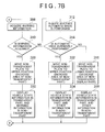
- the display control processing is performed by the display control unit 62 (display control ECU 22) while the ignition switch of a vehicle, on which the in-vehicle system 10 is mounted, is on.
- step 300 of the display control processing the display control unit 62 acquires the information, which indicates the current shift position of the vehicle, from the shift position sensor 39 of the vehicle traveling state acquisition unit 14. This information may be acquired via the automatic drive control ECU 20 rather than directly from the shift position sensor 39.
- step 302 based on the information acquired in step 300, the display control unit 62 determines whether the current shift position of the vehicle is the reverse position.
- step 304 the display control unit 62 acquires the object detection information, which indicates the detection result of the position and the movement speed of an object around the vehicle, from the object detection sensor 32 of the surrounding situation acquisition unit 12. This information may also be obtained via the automatic drive control ECU 20 rather than directly from the object detection sensor 32.
- step 306 based on the object detection information acquired in step 304, the display control unit 62 determines whether there is an object in a blind spot of the driver on a side of the vehicle.
- step 306 the processing proceeds to step 308.
- step 308 the display control unit 62 tries to acquire warning information from the automatic drive control ECU 20.
- step 310 the display control unit 62 determines in step 308 whether warning information could be acquired from the automatic drive control ECU 20, that is, whether warning information was output from the automatic drive control ECU 20.
- step 310 the processing proceeds to step 312.
- step 312 the display control unit 62 inquires of the automatic drive control ECU 20 whether the automatic drive control processing is performed by the automatic drive control unit 46.
- step 314 that follows, based on the inquiry result obtained in step 312, the display control unit 62 determines whether the automatic drive control processing is currently performed for the vehicle.
- step 316 the display control unit 62 controls the non-transparent part increase/decrease unit 78 to move the non-transparent plate 86 to the lower position (the position shown in FIG. 5 ) to increase the area of the transparent display part 94 and to decrease the area of the non-transparent display part 96 (to decrease the area ratio of the area of the non-transparent display part 96 to the area of the transparent display part 94). If the non-transparent plate 86 is already positioned at the lower position, step 316 is skipped.
- step 318 the display control unit 62 controls the driving of the display panel 82 of the HUD 76 such that the vehicle state information indicating the state of the vehicle is displayed in the transparent display part 94 and the other information is displayed in the non-transparent display part 96. That is, the display control unit 62 divides the display part of the display panel 82 into two parts with a division line that corresponds to the boundary between the current transparent display part 94 and the current non-transparent display part 96.
- the display control unit 62 displays the image of information, which is to be displayed in the transparent display part 94, in the part corresponding to the transparent display part 94 that is one of the two parts, and the image of information, which is to be displayed in the non-transparent display part 96, in the part corresponding to the non-transparent display part 96.
- the image displayed in the transparent display part 94 is visually recognized by the driver such that the image is superimposed on the scene in the real space ahead of the vehicle.
- the non-transparent display part 96 the scene in the real space ahead of the vehicle is not visually recognized, but only the image displayed in the non-transparent display part 96 is visually recognized by the driver.
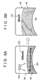
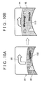
- FIG. 5 and FIG. 10A show the state in which a direction indication mark 98 is displayed
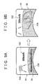
- FIG. 8A , FIG. 9A , and FIG. 11A show the state in which a vehicle icon 100 and a vehicle speed display 102 are displayed.
- FIG. 8A , FIG. 9A , and FIG. 11A show the state in which a music title display 104 being played back on the audio device 27 is displayed
- FIG. 10A shows the state in which the vehicle speed display 102 is displayed.
- step 320 the display control unit 62 controls the non-transparent part increase/decrease unit 78 to move the non-transparent plate 86 to the upper position (the position indicated in FIG. 6 ) to decrease the area of the transparent display part 94 and to increase the area of the non-transparent display part 96 (to increase the area ratio of the area of the non-transparent display part 96 to the area of the transparent display part 94). If the non-transparent plate 86 is already positioned at the upper position, step 320 is skipped.
- step 322 the display control unit 62 controls the driving of the display panel 82 of the HUD 76 such that the vehicle state information, which indicates the state of the vehicle, is displayed in the transparent display part 94 the area of which is decreased (in the transparent display part 94 after the area has been decreased) and such that the image, which is captured by the back image capturing camera 31 and which indicates the situation in back of the vehicle, is displayed in the non-transparent display part 96 the area of which is increased (in the non-transparent display part 94 after the area has been increased).
- FIG. 8B shows an example in which the vehicle speed display 102 is displayed in the transparent display part 94 the area of which is decreased and the rear image 106 indicating the situation in back of the vehicle is displayed in the non-transparent display part 96 the area of which is increased.
- an image displayed in the transparent display part 94 such as the vehicle speed display 102
- the driver is visually recognized by the driver as an image superimposed on the scene in the real space ahead of the vehicle.
- a rear image 106 which indicates the situation of the space in back of the vehicle displayed in the non-transparent display part 96, is visually recognized by the driver with high visibility without being affected by the brightness and the color tone of the scene in the real space ahead of the vehicle.
- the driver has a need to know the situation in back of the vehicle.
- the area of the non-transparent display part 96 is increased and, in the non-transparent display part 96 the area of which is increased, the rear image 106 indicating the situation in back of the vehicle is displayed with high visibility. This allows the driver, who references the displayed rear image 106, to know the situation in back of the vehicle, thus increasing safety.
- step 306 determines whether there is an object in a blind spot on a side of the vehicle. If it is determined, based on the object detection information acquired in step 304, that there is an object in a blind spot on a side of the vehicle, the determination in step 306 is affirmative and the processing proceeds to step 324.
- the display control unit 62 controls the non-transparent part increase/decrease unit 78 to move the non-transparent plate 86 to the upper position (the position indicated in FIG. 6 ) to decrease the area of the transparent display part 94 and to increase the area of the non-transparent display part 96. If the non-transparent plate 86 is already positioned at the upper position, step 324 is skipped.
- step 326 the display control unit 62 controls the driving of the display panel 82 of the HUD 76 such that the vehicle state information, which indicates the state of the vehicle, is displayed in the transparent display part 94 the area of which is decreased and such that the image, which is captured by the side image capturing camera 33 and which indicates the situation on side of the vehicle including the blind spot of the driver, is displayed in the non-transparent display part 96 the area of which is increased.
- FIG. 9B shows an example in which the vehicle speed display 102 is displayed in the transparent display part 94 the area of which is decreased and a side image 108 indicating the situation on side of the vehicle is displayed in the non-transparent display part 96 the area of which is increased.
- an image displayed in the transparent display part 94 such as the vehicle speed display 102
- the driver is visually recognized by the driver as an image superimposed on the scene in the real space ahead of the vehicle.
- the side image 108 which indicates the situation on side of the vehicle displayed in the non-transparent display part 96, is visually recognized by the driver with high visibility without being affected by the brightness and the color tone of the scene in the real space ahead of the vehicle.
- the driver is required to recognize the object in the blind spot and to pay attention to the object.
- the area of the non-transparent display part 96 is increased and, in the non-transparent display part 96 the area of which is increased, the side image 108, which indicates the situation on the side of the vehicle that includes the blind spot of the driver, is displayed with high visibility. This allows the driver, who references the displayed side image 108, to recognize the object in the blind spot on the side of the vehicle and to pay attention to that object, thus increasing safety.
- step 328 the display control unit 62 controls the non-transparent part increase/decrease unit 78 to move the non-transparent plate 86 to the upper position (the position indicated in FIG. 6 ) to decrease the area of the transparent display part 94 and to increase the area of the non-transparent display part 96. If the non-transparent plate 86 is already positioned at the upper position, step 328 is skipped.
- step 330 the display control unit 62 controls the driving of the display panel 82 of the HUD 76 such that the vehicle state information, which indicates the state of the vehicle, is displayed in the transparent display part 94 the area of which is decreased and such that the image of the warning to the driver, which indicates the warning information acquired from the automatic drive control ECU 20, is displayed in the non-transparent display part 96 the area of which is increased.
- FIG. 330 the display control unit 62 controls the driving of the display panel 82 of the HUD 76 such that the vehicle state information, which indicates the state of the vehicle, is displayed in the transparent display part 94 the area of which is decreased and such that the image of the warning to the driver, which indicates the warning information acquired from the automatic drive control ECU 20, is displayed in the non-transparent display part 96 the area of which is increased.
- FIG. 10B shows an example in which the direction indication mark 98 is displayed in the transparent display part 94 the area of which is decreased and a warning image 110, which indicates an abnormal exhaust-gas temperature and an engine malfunction (for example, an image in which the brightness of the characters of "Warning" is periodically switched between high brightness and low brightness), is displayed in the non-transparent display part 96 the area of which is increased.
- a warning image 110 which indicates an abnormal exhaust-gas temperature and an engine malfunction (for example, an image in which the brightness of the characters of "Warning" is periodically switched between high brightness and low brightness), is displayed in the non-transparent display part 96 the area of which is increased.
- an image displayed in the transparent display part 94 is visually recognized by the driver as an image superimposed on the scene in the real space ahead of the vehicle.
- the warning image 110 displayed in the non-transparent display part 96 is visually recognized by the driver with high visibility without being affected by the brightness and the color tone of the scene in the real space ahead of the vehicle.
- the warning image 110 described above is displayed in the transparent display part 94, its visibility may be decreased due to the effect of the brightness and the color tone of the scene in the real space ahead of the vehicle. A decrease in the visibility of the warning image 110 may lead to a situation in which the warning is not recognized by the driver or is wrongly recognized by the driver as a low-warning-level warning.
- warning information is output from the automatic drive control ECU 20
- the area of the non-transparent display part 96 is increased in this embodiment and, in the non-transparent display part 96 the area of which is increased, the warning image 110 indicating warning information is displayed with high visibility.
- the warning image 110 displayed in this manner allows the driver to recognize the warning, thus increasing safety.
- step 314 the determination in step 314 is affirmative and the processing proceeds to step 332.
- the display control unit 62 controls the non-transparent part increase/decrease unit 78 to move the non-transparent plate 86 to the upper position (the position indicated in FIG. 6 ) to decrease the area of the transparent display part 94 and to increase the area of the non-transparent display part 96. If the non-transparent plate 86 is already positioned at the upper position, step 332 is skipped.
- step 334 the display control unit 62 controls the driving of the display panel 82 of the HUD 76 such that the vehicle state information, which indicates the state of the vehicle, is displayed in the transparent display part 94 the area of which is decreased and such that the image, which indicates the information other than the information about the state of the vehicle, such as car navigation information or announcement/entertainment related information received from the audio device, is displayed in the non-transparent display part 96 the area of which is increased.
- FIG. 11B shows an example in which the vehicle speed display 102 is displayed in the transparent display part 94 the area of which is decreased and a spectrum analyzer image 112 of the music played back on the audio device 27 is displayed in the non-transparent display part 96 the area of which is increased.
- an image displayed in the transparent display part 94 such as the vehicle speed display 102, is visually recognized by the driver as an image superimposed on the scene in the real space ahead of the vehicle.
- the spectrum analyzer image 112 which is displayed in the non-transparent display part 96, is visually recognized by the driver with high visibility without being affected by the brightness and the color tone of the scene in the real space ahead of the vehicle.
- the automatic drive control processing is performed by the automatic drive control unit 46, it is assumed that the load on the driver is reduced and that the amount of information to be transmitted to the driver, which indicates the state of the vehicle is reduced. Accordingly, if the automatic drive control processing is performed by the automatic drive control unit 46, the area of the non-transparent display part 96 is increased and, in the non-transparent display part 96 the area of which is increased, the image of announcement/entertainment related information such as the spectrum analyzer image 112 is displayed with high visibility. This allows the image of information/entertainment related information to be displayed with high visibility without compromising safety.
- the configuration of the non-transparent part increase/decrease unit 78 is not limited to the configuration shown in FIG. 4 .
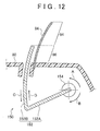
- Other configurations of the non-transparent part increase/decrease unit 78 are described below with reference to FIG. 12 to FIG. 15 .
- a non-transparent part increase/decrease unit 150 shown in FIG. 12 has a non-transparent member 152 that is made of a non-transparent material and has a flat, rectangular shape.
- the non-transparent member 152 is bent at the intermediate portion in the short side direction to form a base part 152A and an arc part 152B.
- the arc part 152B of the non-transparent member 152 is slightly curved in the longitudinal direction of the vehicle, and the non-transparent member 152 is arranged such that the arc part 152B is roughly parallel with the combiner 84.
- the base part 152A of the non-transparent member 152 has the end, on the side opposite to the arc part 152B, mounted on the rotation axis of a motor 154.
- the non-transparent member 152 can move rotationally about the rotation axis of the motor 154.
- the rotation axis of the motor 154 rotates counterclockwise in FIG. 12 (in the direction indicated by arrow A in FIG. 12 )
- the non-transparent member 152 moves rotationally in the direction in which the arc part 152B lowers (in the direction indicated by arrow C in FIG. 12 ).
- the rotation axis of the motor 154 rotates clockwise in FIG. 12 (in the direction indicated by arrow B in FIG. 12 )
- the non-transparent member 152 moves rotationally in the direction in which the arc part 152B rises (in the direction indicated by arrow D in FIG. 12 ).
- the arc part 152B of the non-transparent member 152 shields a part of a lower side of a light flux that is directed from the space ahead of the vehicle to the driver's eyes through the combiner 84.
- the shielding amount of a light flux varies and, as this amount varies, the area of the non-transparent display part 96 corresponding to the arc part 152B of the non-transparent member 152 varies.
- the non-transparent part increase/decrease unit 150 controls the rotation direction and the rotation amount of the rotation axis of the motor 154 to change the area ratio between the transparent display part 94 and the non-transparent display part 96.
- a non-transparent part increase/decrease unit 160 shown in FIG. 13 has a non-transparent plate 162 that is made of a non-transparent material and has a flat, rectangular shape.
- the non-transparent plate 162 has one of long sides mounted on the rotation axis of a motor 164. Therefore, the non-transparent plate 162 can move rotationally about the rotation axis of the motor 164.
- the shielding amount (area of the non-transparent display part 96) of a light flux that is directed from the space ahead of the vehicle to the driver's eyes through the combiner 84 varies.
- the non-transparent part increase/decrease unit 160 controls the rotation direction and the rotation amount of the rotation axis of the motor 164 to change the area ratio between the transparent display part 94 and the non-transparent display part 96.
- a non-transparent part increase/decrease unit 170 shown in FIGS. 14A to 14C has a non-transparent plate 172 that is made of a non-transparent material and has a flat, almost-rectangular shape.
- This non-transparent plate 172 has a cutout 172A.
- the non-transparent plate 172 has a rotation center 172E at a position the distances of which to the three sides 172B to 172D, other than the side on which the cutout 172A is provided, are different from each other (dB ⁇ dC ⁇ dD : see FIG. 14A ).
- the non-transparent plate 172 is mounted with this rotation center 172E on the rotation axis of a motor 190.
- the non-transparent plate 172 when the non-transparent plate 172 is positioned at the position indicated in FIG. 14A , the amount of its protrusion (shielding amount of a light flux) into the optical path of a light flux, directed from the space ahead of the vehicle to the driver's eyes through the combiner 84, is minimized and, as this amount is minimized, the area of the non-transparent display part 96 is also minimized.
- the non-transparent plate 172 is positioned at the position indicated in FIG.
- the amount of its protrusion (shielding amount of a light flux) into the optical path of a light flux, directed from the space ahead of the vehicle to the driver's eyes through the combiner 84, is intermediate and, as this amount is intermediate, the area of the non-transparent display part 96 is also intermediate.
- the non-transparent plate 172 is positioned at the position indicated in FIG. 14C , the amount of its protrusion (shielding amount of a light flux) into the optical path of a light flux, directed from the space ahead of the vehicle to the driver's eyes through the combiner 84, is maximized and, as this amount is maximized, the area of the non-transparent display part 96 is also maximized.
- the non-transparent part increase/decrease unit 170 controls the rotation direction and the rotation amount of the rotation axis of the motor to change the area ratio between the transparent display part 94 and the non-transparent display part 96.
- a non-transparent part increase/decrease unit 180 shown in FIG. 15 has a plurality of transmissivity changing parts 182A to 182D each of which is rectangular with the transverse direction of the combiner 84 as the longitudinal direction.
- the transmissivity changing parts 182A to 182D arranged along the up-down direction of the combiner 84, change the light transmissivity by turning on or off the application of voltage to electrodes 184 and 186 provided on both sides in the transverse direction of the combiner 84.
- the non-transparent part increase/decrease unit 180 has a driving circuit 192 that independently controls turning on or off the application of voltage to the transmissivity changing parts 182A to 182D.
- the non-transparent part increase/decrease unit 180 decreases the light transmissivity of a predetermined number of transmissivity changing parts 182, sequentially in order of the vehicle's up-down direction beginning with the transmissivity changing part 182A positioned at the lower position, so that the number of transmissivity changing parts 182 for decreasing the light transmissivity will be increased. This decreases the area of the transparent display part 94 and increases the area of the non-transparent display part 96.
- the non-transparent part increase/decrease unit 180 increases the light transmissivity of a predetermined number of transmissivity changing parts 182, sequentially in order of the vehicle's up-down direction beginning with the transmissivity changing part 182D positioned at the upper position, so that the number of transmissivity changing parts 182 for decreasing the light transmissivity will be decreased. This increases the area of the transparent display part 94 and decreases the area of the non-transparent display part 96.
- the display control program 70 in this embodiment may also be provided as a form stored in a storage medium such as a CD-ROM or a DVD-ROM.
- the present invention is not limited to this configuration. Another configuration is also possible in which one ECU performs each of the automatic drive control processing and the display control processing.
Landscapes
- Engineering & Computer Science (AREA)
- Mechanical Engineering (AREA)
- Chemical & Material Sciences (AREA)
- Combustion & Propulsion (AREA)
- Transportation (AREA)
- Physics & Mathematics (AREA)
- Multimedia (AREA)
- General Physics & Mathematics (AREA)
- Optics & Photonics (AREA)
- Nonlinear Science (AREA)
- Signal Processing (AREA)
- Theoretical Computer Science (AREA)
- Instrument Panels (AREA)
- Fittings On The Vehicle Exterior For Carrying Loads, And Devices For Holding Or Mounting Articles (AREA)
Abstract
An embodiment of an in-vehicle display device includes: a display unit (26) that includes a transparent display part and a low-transmissivity display part, and that changes an area ratio of an area of the low-transmissivity display part to an area of the transparent display part; an image capturing unit (31, 33) that captures a space around the vehicle as an image; and a first display control unit (22) configured to control the display unit (26) such that the area ratio is increased when a predetermined condition is satisfied as compared to when the predetermined condition is not satisfied, and the image captured by the image capturing unit is displayed in the low-transmissivity display part after the area ratio has been increased.

Description
- The present invention relates to an in-vehicle display device.
- Japanese Patent Application Publication No.
2008-209724 JP 2008-209724 A - The spatial distribution of the real-space scene ahead of the vehicle is not constant in brightness and color tone and, in addition, the spatial distribution of brightness and color tone varies as the time elapses. Therefore, when an image is superimposed on the real-space scene ahead of the vehicle by means of the in-vehicle head-up display, the visibility varies because it is affected by the brightness and the color tone of the real-space scene ahead of the vehicle. The visibility of some of the images displayed on the in-vehicle head-up display is easily decreased by the effect of the brightness and the color tone of the real-space scene ahead of the vehicle. Therefore, there is a possibility that superimposing these types of images on the real-space scene ahead of the vehicle significantly decreases the visibility, makes it difficult to transmit information to the driver smoothly, and hinders the driver's visibility of the real-space scene ahead of the vehicle.
- The present invention provides an in-vehicle display device that can display information, not suitable for being superimposed on the real-space scene ahead of a vehicle, while ensuring visibility and safety.
- A first aspect of the invention relates to an in-vehicle display device including: a display unit that includes a transparent display part and a low-transmissivity display part, and that changes an area ratio of an area of the low-transmissivity display part to an area of the transparent display part, the transparent display part being a part through which a light from a real space ahead of a vehicle transmits and in which an image is superimposed on a scene in the real space, the low-transmissivity display part being a part a light transmissivity of which for a light from the real space is lower than a light transmissivity of the transparent display part and in which an image is displayed; an image capturing unit that captures a space around the vehicle as an image; and a first display control unit configured to control the display unit such that the area ratio is increased when a predetermined condition is satisfied as compared to when the predetermined condition is not satisfied, and the image captured by the image capturing unit is displayed in the low-transmissivity display part after the area ratio has been increased.
- An image obtained by capturing the space around the vehicle is very useful information for the driver. However, the image described above is an image that represents the situation of the space in back of the vehicle based on the spatial distribution of the brightness and the color tone of each pixel as well as their changes over time. Therefore, when this image is superimposed on the scene in the real space ahead of the vehicle, the visibility is easily decreased by the effect of the brightness and the color tone of the scene in the real space ahead of the vehicle, meaning that this image is not suitable for being superimposed on the scene in the real space ahead of the vehicle.
- According to the configuration described above, the display unit includes the transparent display part, which is a part through which a light from the real space ahead of a vehicle transmits and in which an image can be superimposed on a scene in the real space, and the low-transmissivity display part, which is a part the light transmissivity of which for a light from the real space is lower than the light transmissivity of the transparent display part and in which an image can be displayed. In addition, the area ratio of the area the low-transmissivity display part to the area the transparent display part can be changed in the display unit. The display unit is controlled such that the area ratio is increased when the predetermined condition is satisfied as compared to when the predetermined condition is not satisfied, and the image of the space around the vehicle is displayed in the low-transmissivity display part after the area ratio has been increased. This allows the information (the image of the space around the vehicle), which is not suitable for being superimposed on the scene in the real space ahead of the vehicle, to be displayed while ensuring visibility and safety.
- The image capturing unit may include a first image capturing unit that captures a space in back of the vehicle as an image. In this case, the first display control unit may be configured to control the display unit such that the area ratio is increased when a shift position of the vehicle is a reverse position as compared to when the shift position is not the reverse position, and the image captured by the first image capturing unit is displayed in the low-transmissivity display part after the area ratio has been increased.
- An image obtained by capturing the space in back of the vehicle is very useful information for the driver when driving the vehicle in the reverse direction. However, the image described above is an image that represents the situation of the space in back of the vehicle based on the spatial distribution of the brightness and the color tone of each pixel as well as their changes over time. Therefore, when this image is superimposed on the scene in the real space ahead of the vehicle, the visibility is easily decreased by the effect of the brightness and the color tone of the scene in the real space ahead of the vehicle, meaning that this image is not suitable for being superimposed on the scene in the real space ahead of the vehicle. On the other hand, when the shift position of the vehicle is the reverse position, the driver is required to know the situation in back of the vehicle.
- According to the configuration described above, the display unit includes the transparent display part, which is a part through which a light from the real space ahead of a vehicle transmits and in which an image can be superimposed on a scene in the real space, and the low-transmissivity display part, which is a part the light transmissivity of which for a light from the real space is lower than the light transmissivity of the transparent display part and in which an image can be displayed. In addition, the area ratio of the area the low-transmissivity display part to the area the transparent display part can be changed in the display unit. The display unit is controlled such that the area ratio is increased when the shift position of the vehicle is the reverse position as compared to when the shift position is not the reverse position, and the image of the space in back of the vehicle is displayed in the low-transmissivity display part after the area ratio has been increased. This allows the information (the image of the space in back of the vehicle), which is not suitable for being superimposed on the scene in the real space ahead of the vehicle, to be displayed while ensuring visibility and safety.
- The in-vehicle display device may further include an object detection unit that detects an object in a blind spot of a driver, on a side of the vehicle, and the image capturing unit may include a second image capturing unit that captures a space on the side of the vehicle, which includes the blind spot, as an image. In this case, the first display control unit may be configured to control the display unit such that the area ratio is increased when an object in the blind spot is detected by the object detection unit as compared to when an object in the blind spot is not detected, and the image captured by the second image capturing unit is displayed in the low-transmissivity display part after the area ratio has been increased.
- An image, obtained by capturing a space on a side of the vehicle, which includes a blind spot of the driver, is very useful information for the driver especially when there is an object in the blind spot. However, the image described above is also an image that represents the situation of the space on side of the vehicle based on the spatial distribution of the brightness and the color tone of each pixel as well as their changes over time. Therefore, when this image is superimposed on the scene in the real space ahead of the vehicle, the visibility is easily decreased by the effect of the brightness and the color tone of the scene in the real space ahead of the vehicle, meaning that this image is not suitable for being superimposed on the scene in the real space ahead of the vehicle. On the other hand, when there is an object in a blind spot of the driver, the driver is required to recognize the object in the blond spot and to pay attention to the object.
- According to the configuration described above, the display unit includes the transparent display part, which is a part through which a light from the real space ahead of a vehicle transmits and in which an image can be superimposed on a scene in the real space, and the low-transmissivity display part, which is a part the light transmissivity of which for a light from the real space is lower than the light transmissivity of the transparent display part and in which an image can be displayed. In addition, the area ratio of the area of the low-transmissivity display part to the area of the transparent display part and can be changed in the display unit. The display unit is controlled such that the area ratio is increased when an object in the blind spot of the driver is detected by the object detection unit as compared when an object in the blind spot is not detected, and the image of a space on side of the vehicle, which includes the blind spot of the driver, is displayed in the low-transmissivity display part after the area ratio has been increased. This allows the information (the image of a space on side of the vehicle, which includes a blind spot of the driver), which is not suitable for being superimposed on the scene in the real space ahead of the vehicle, to be displayed while ensuring visibility and safety.
- A second aspect of the invention relates to an in-vehicle display device including: a display unit that includes a transparent display part and a low-transmissivity display part, and that changes an area ratio of an area of the low-transmissivity display part to an area of the transparent display part, the transparent display part being a part through which a light from a real space ahead of a vehicle transmits and in which an image is superimposed on a scene in the real space, the low-transmissivity display part being a part a light transmissivity of which for a light from the real space is lower than a light transmissivity of the transparent display part and in which an image is displayed; a warning determination unit configured to determine whether a warning is to be issued to a driver; and a second display control unit configured to control the display unit such that the area ratio is increased when the warning determination unit determines that a warning is to be issued to the driver as compared to when the warning determination unit does not determine that a warning is to be issued to the driver, and information indicating the warning to be issued to the driver is displayed as an image in the low-transmissivity display part after the area ratio has been increased.
- If, when a warning is to be issued to the driver, the information indicating the warning to be issued to the driver is superimposed on the scene of the real space ahead of the vehicle as an image and if the visibility of the image is decreased by the effect of the brightness and the color tone of the scene in the real space ahead of the vehicle, there is a possibility that the warning is not recognized by the driver or is wrongly recognized by the driver as a low-warning-level warning.
- According to the configuration described above, the display unit includes the transparent display part, which is a part through which a light from the real space ahead of a vehicle transmits and in which an image can be superimposed on a scene in the real space, and the low-transmissivity display part, which is a part the light transmissivity of which for a light from the real space is lower than the light transmissivity of the transparent display part and in which an image can be displayed. In addition, the area ratio of the area the low-transmissivity display part to the area of the transparent display part can be changed in the display unit. The display unit is controlled such that the area ratio is increased when the warning determination unit determines that a warning is to be issued to a driver as compared to when the warning determination unit does not determine that a warning is to be issued to a driver, and information, which indicates the warning to be issued to the driver, is displayed as an image in the low-transmissivity display part after the area ratio has been increased. This allows the information (the image of the information indicating the warning to be issued to the driver), which is not suitable for being superimposed on the scene in the real space ahead of the vehicle, to be displayed while ensuring visibility and safety.
- A third aspect of the invention relates to an in-vehicle display device including: a display unit that includes a transparent display part and a low-transmissivity display part, and that changes an area ratio of an area of the low-transmissivity display part to an area of the transparent display part, the transparent display part being a part through which a light from a real space ahead of a vehicle transmits and in which an image is superimposed on a scene in the real space, the low-transmissivity display part being a part a light transmissivity of which for a light from the real space is lower than a light transmissivity of the transparent display part and in which an image is displayed; a drive assist unit configured to perform drive assist processing that assists a driver in driving the vehicle; and a third display control unit configured to control the display unit such that the area ratio is increased when the drive assist unit performs the drive assist processing as compared to when the drive assist unit does not perform the drive assist processing, and information other than information indicating a state of the vehicle is displayed as an image in the low-transmissivity display part after the area ratio has been increased.
- When the information other than the information indicating the state of the vehicle is superimposed on the scene in the real space ahead of the vehicle, there is a high possibility that the visibility is easily decreased by the effect of the brightness and the color tone of the scene in the real space ahead of the vehicle. On the other hand, while the drive assist processing that assists the driver in driving the vehicle is performed by the drive assist unit, it is assumed that the load on the driver is reduced and that the amount of information that indicates the state of the vehicle and is to be transmitted to the driver is reduced.
- According to the configuration described above, the display unit includes the transparent display part, which is a part through which a light from the real space ahead of a vehicle transmits and in which an image can be superimposed on a scene in the real space, and the low-transmissivity display part, which is a part the light transmissivity of which for a light from the real space is lower than the light transmissivity of the transparent display part and in which an image can be displayed. In addition, the area ratio of the area of the low-transmissivity display part to the area of the transparent display part can be changed. The display unit is controlled such that the area ratio is increased when the drive assist processing that assists the driver in driving the vehicle is performed as compared to when the drive assist processing is not performed, and the information, which indicates the information other than the information indicating the state of the vehicle, is displayed as an image in the low-transmissivity display part after the area ratio has been increased. This allows the information (the image of the information other than the information indicating the state of the vehicle), which is not suitable for being superimposed on the scene in the real space ahead of the vehicle, to be displayed while ensuring visibility and safety.
- The display unit may include a combiner, provided between a windshield glass and an instrument panel of the vehicle, and a low-transmissivity part increase/decrease unit that changes the area ratio. A display part of the combiner may be divided into the transparent display part and the low-transmissivity display part.
- The low-transmissivity part increase/decrease unit may include a low-transparency member that shields or reduces a part of a lower side of a light flux, directed from the real space toward the driver through the combiner, and an actuator that moves the low-transparency member with respect to the combiner. In this case, the transparent display part may correspond to a part of the light flux not shielded or reduced by the low-transparency member, and the low-transmissivity display part may correspond to the part of the light flux shielded or reduced by the low-transparency member, and the area ratio may be changed when the low-transparency member is moved with respect to the combiner.
- The actuator may move the low-transparency member with respect to the combiner along an up-down direction of the combiner, and the area ratio may be changed when the low-transparency member is moved along the up-down direction.
- The actuator may rotate the low-transparency member with respect to the combiner about an axis along a transverse direction of the vehicle or an axis along a longitudinal direction of the vehicle, and the area ratio may be changed when the low-transparency member is rotated.
- The low-transmissivity part increase/decrease unit may include a plurality of transmissivity changing parts provided along an up-down direction of the combiner, and a driving circuit. A light transmissivity of each of the plurality of transmissivity changing parts may be changed by turning on or off an application of voltage, and the driving circuit may control turning on or off the application of voltage to the plurality of transmissivity changing parts. The area ratio may be changed when the number of the transmissivity changing parts the light transmissivity of which is decreased is changed by the driving circuit.
- According to the configurations described above, the information, not suitable for being superimposed on the real-space scene ahead of a vehicle, can be displayed while ensuring visibility and safety.
- Features, advantages, and technical and industrial significance of exemplary embodiments of the invention will be described below with reference to the accompanying drawings, in which like numerals denote like elements, and wherein:
-
FIG. 1 is a block diagram showing a general configuration of an in-vehicle system in an embodiment; -
FIG. 2A is a block diagram showing a general configuration of an automatic drive control ECU, andFIG. 2B is a block diagram showing a general configuration of a display control ECU; -
FIG. 3 is a general configuration diagram showing a head-up display (HUD); -
FIG. 4 is a cross section diagram showing an example of a non-transparent part increase/decrease unit; -
FIG. 5 is an image diagram showing the driver's visual field when a non-transparent plate is positioned in a lower position; -
FIG. 6 is an image diagram showing the driver's visual field when a non-transparent plate is positioned in an upper position; -
FIG. 7A and7B are flowcharts showing the contents of the display control processing; -
FIGS. 8A and 8B are image diagrams showing an example of change in the display on the HUD when the shift position is the reverse position; -
FIGS. 9A and 9B are image diagrams showing an example of change in the display on the HUD when an object appears in a blind spot; -
FIGS. 10A and 10B are image diagrams showing an example of change in the display on the HUD when warning information is output; -
FIGS. 11A and 11B are image diagrams showing an example of change in the display on the HUD when an automatic drive is started; -
FIG. 12 is a cross section diagram showing another example of the non-transparent part increase/decrease unit; -
FIG. 13 is a cross section diagram showing another example of the non-transparent part increase/decrease unit; -
FIGS. 14A to 14C are cross section diagrams showing another example of the non-transparent part increase/decrease unit; and -
FIG. 15 is a plan view showing another example of the non-transparent part increase/decrease unit. - An example of an embodiment of the present invention is described below in detail with reference to the drawings.
FIG. 1 shows the general configuration of an in-vehicle system 10 mounted on a vehicle. This in-vehicle system 10 functions also as an in-vehicle display device according to the present invention. InFIG. 1 , the figure of a part, included in the in-vehicle system 10 but not related to the present invention, is omitted. - The in-
vehicle system 10 includes a surroundingsituation acquisition unit 12, a vehicle travelingstate acquisition unit 14, a driverstate acquisition unit 16, a mapinformation storage unit 18, an automaticdrive control ECU 20, adisplay control ECU 22, aninput unit 24, adisplay unit 26, and anaudio device 27. The surroundingsituation acquisition unit 12, vehicle travelingstate acquisition unit 14, driverstate acquisition unit 16, automaticdrive control ECU 20,display control ECU 22,input unit 24,display unit 26, andaudio device 27 are interconnected via a bus 11. - The surrounding
situation acquisition unit 12 acquires information indicating the situation of the vehicle's surrounding environment. The surroundingsituation acquisition unit 12 includes aGPS device 28, an in-vehicle communication unit 30, a backimage capturing camera 31, a sideimage capturing camera 33, anobject detection sensor 32, and anavigation system 34. - The Global Positioning System (GPS)
device 28 receives GPS signals from a plurality of GPS satellites to measure the position of the vehicle. The greater the number of GPS signals, the higher the measuring accuracy of theGPS device 28. The in-vehicle communication unit 30 is a communication device that carries out at least one of the vehicle-vehicle communication with another vehicle and the road-vehicle communication with a roadside unit. - The back
image capturing camera 31 captures the space in back of the vehicle as an image. The backimage capturing camera 31 is an example of a first image capturing unit. The sideimage capturing camera 33 captures the space on a side of the vehicle as an image. The image capturing range of the sideimage capturing camera 33 includes a blind spot of the driver. The blind spot is a space around the vehicle, not directly observed by the driver. The sideimage capturing camera 33 is an example of a second image capturing unit. - The
object detection sensor 32, which includes at least one of a millimeter wave radar and an ultrasonic sonar, detects the position and the movement speed of an object around the vehicle, such as a vehicle, pedestrian, store, and obstacle. The object detection range of theobject detection sensor 32 includes a blind spot of the driver on a side of the vehicle. Theobject detection sensor 32 is an example of an object detection unit. Thenavigation system 34 displays the position of the vehicle on the map, or a suggested route to a traveling destination, based on the position information from theGPS device 28 and the map information. - The vehicle traveling
state acquisition unit 14 acquires information indicating the traveling state and the operation state of the vehicle. The vehicle travelingstate acquisition unit 14 includes asteering angle sensor 36, avehicle speed sensor 38, ashift position sensor 39, ablinker sensor 40, and alight sensor 42. Thesteering angle sensor 36 is a sensor that detects the steering angle of the vehicle, and thevehicle speed sensor 38 is a sensor that detects the traveling speed of the vehicle. Theshift position sensor 39 is a sensor that detects the shift position of the vehicle (for example, the gear positions of the transmission). Theblinker sensor 40 is a sensor that detects the direction indicated by the direction indicator switch lever of the vehicle, and thelight sensor 42 is a sensor that detects the on/off state of the light of the vehicle. In addition to the sensors described above, a sensor that detects at least one of the brake pedal depression amount and the wiper operation state may also be provided. - The driver
state acquisition unit 16 acquires the information indicating the driver state. The driver state is a state indicating whether the driver is drowsy, inattentive, excited, or calm. The driverstate acquisition unit 16, which includes an in-vehicle camera 44, senses bio-information, including at least one of driver's line of sight, face direction, movement of the eyes, and movement of the face, through image recognition and, based on the sensed bio-information, senses the driver state. In addition to the in-vehicle camera 44, a directional microphone that acquires sounds in the vehicle, a biosensor provided on the steering wheel, or a brain wave sensor may be used to sense the driver state. - The automatic
drive control ECU 20 includes an automaticdrive control unit 46 that performs the automatic drive control processing. As the drive assist processing that assists the driver in driving the vehicle, the automatic drive control processing enables the vehicle (host vehicle), on which the in-vehicle system 10 is mounted, to travel automatically without driver's driving operation. As shown inFIG. 2A , the automaticdrive control ECU 20 includes aCPU 48, amemory 50, anonvolatile storage unit 52 that stores an automaticdrive control program 56, and a communication interface (I/F)unit 58 that carries out communication with the sensors and actuators. These components are interconnected via abus 60. The automaticdrive control ECU 20 works as the automaticdrive control unit 46 when the automaticdrive control program 56 is read from thestorage unit 52 for expansion into thememory 50 and the automaticdrive control program 56, expanded in thememory 50, is executed by theCPU 48. - To allow the vehicle to travel automatically, the automatic
drive control unit 46 determines the situation of the vehicle and its surroundings based on the information obtained from the sensors and performs the automatic drive control processing that controls the accelerator amount, brake amount, and steering angle amount. In this embodiment, the automatic drive control processing performed by the automaticdrive control unit 46 includes the processing for determining whether the state of the vehicle and its surroundings is in a situation in which a warning to the driver is required and, if so, for outputting the warning information indicating a warning to be issued to the driver. The situation in which a warning is required to the driver includes a case in which an emergency vehicle is approaching the vehicle, in which the entrance of the road the vehicle is going to enter is the exit of a one-way road, and in which the distance between the preceding vehicle traveling ahead and the vehicle becomes smaller than a predetermined distance. Because the automatic drive control processing by the automaticdrive control unit 46 can be implemented by a known technology, its detailed description is omitted. The automaticdrive control unit 46 is an example of a warning determination unit and a drive assist unit. - On the other hand, as shown in
FIG. 1 , thedisplay control ECU 22 includes adisplay control unit 62 that controls image display on a head-up display (hereinafter called a HUD 76) that will be described later. As shown inFIG. 2B , thedisplay control ECU 22 includes aCPU 64, amemory 66, anonvolatile storage unit 68 that stores adisplay control program 70, and a communication interface (I/F)unit 72 that carries out communication with an external device. These components are interconnected via abus 74. Thedisplay control ECU 22 works as thedisplay control unit 62 when thedisplay control program 70 is read from thestorage unit 68 for expansion into thememory 66 and thedisplay control program 70, expanded in thememory 66, is executed by theCPU 64. Thedisplay control unit 62 is an example of a first display control unit to a third display control unit. - The
input unit 24, used by the driver to enter information into the automaticdrive control ECU 20, includes at least one of a button, a switch, and a touch screen. The driver enters an automatic drive start instruction and an automatic drive termination instruction into the automaticdrive control ECU 20 via theinput unit 24. - The
display unit 26 includes theHUD 76, which presents information from the automaticdrive control ECU 20 to the driver, and a non-transparent part increase/decrease unit 78. TheHUD 76 includes adisplay panel 82 and acombiner 84 as shown inFIG. 3 . Thedisplay panel 82, embedded in aninstrument panel 80, emits a light flux spatially modulated according to a display image to be projected on theHUD 76. Thecombiner 84, formed of a material the light transmissivity of which is equal to or higher than a predetermined value, is installed between awindshield glass 79 of the vehicle and theinstrument panel 80. On thiscombiner 84, a display image, represented by the light flux emitted from thedisplay panel 82, is projected in the driver's visual field in front of the driver's seat. - The
HUD 76 receives an instruction, which specifies an image to be displayed on thecombiner 84, from thedisplay control ECU 22 and controls the driving of thedisplay panel 82 according to the specified image. Then, the light flux, emitted from thedisplay panel 82, is focused on thecombiner 84, and the image, specified by thedisplay control ECU 22, is enlarged and projected on thecombiner 84. This allows the driver to visually recognize the enlarged and projected image that is superimposed on the scene in the real space ahead of the vehicle. The configuration of theHUD 76 is not limited to the configuration shown inFIG. 3 , but another known configuration may also be used. - On the other hand, the non-transparent part increase/
decrease unit 78 has anon-transparent plate 86 that is made of a non-transparent material and has a flat, rectangular shape. Thenon-transparent plate 86, provided in roughly parallel with thecombiner 84 at a predetermined interval, can move in the up-down direction of the vehicle while keeping roughly parallel to thecombiner 84. As shown inFIG. 4 , thecombiner 84 has a shape slightly curved in the longitudinal direction of the vehicle and, in conformity with thecombiner 84, thenon-transparent plate 86 also has a shape slightly curved in the longitudinal direction of the vehicle. Thenon-transparent plate 86 has arack 88 formed at one end of the transverse direction of the vehicle. Therack 88 is engaged with apinion gear 92 mounted on the rotation axis of amotor 90. Thenon-transparent plate 86 moves downward when thepinion gear 92 is turned counterclockwise inFIG. 4 (in the direction indicated by arrow A inFIG. 4 ) by themotor 90, and moves upward when thepinion gear 92 is turned clockwise inFIG. 4 (in the direction indicated by arrow B inFIG. 4 ) by themotor 90. - The
non-transparent plate 86 shields a part of a lower side of a light flux that is directed from the space ahead of the vehicle to the driver's eyes through the combiner 84 (a light flux directed from the space ahead of the vehicle toward the driver through the combiner 84). As thenon-transparent plate 86 is moved in the up-down direction by the driving force of themotor 90, the light-flux shielding amount (cross-section area that is shielded) varies and, as this amount varies, the area of the display part corresponding to the non-transparent plate 86 (non-transparent display part 96) varies. Themotor 90 of the non-transparent part increase/decrease unit 78 moves thenon-transparent plate 86 to the lower position around the lower-limit position in the up-down movement of thenon-transparent plate 86 or to the upper position around the upper-limit position in the up-down movement of thenon-transparent plate 86. - A
transparent display part 94 is a part of the whole display part and corresponds to the light flux directed from the space ahead of the vehicle to the driver's eyes through thecombiner 84 without being shielded by thenon-transparent plate 86. Thenon-transparent display part 96 is a part of the whole display part and corresponds to the non-transparent plate 86 (the light flux shielded by the non-transparent plate 86). The above whole display part corresponds to the whole surface of thecombiner 84. When thenon-transparent plate 86 is positioned at the lower position, the position of the boundary between thetransparent display part 94 and thenon-transparent display part 96 is approximately equal in height to the position of the boundary between thewindshield glass 79 of the vehicle, as viewed by the driver, and theinstrument panel 80 as shown inFIG. 5 . - On the other hand, when the
non-transparent plate 86 is positioned at the upper position, the area of thetransparent display part 94 is decreased and the area of thenon-transparent display part 96 is increased, as compared to the case in which thenon-transparent plate 86 is positioned in the lower position, as shown inFIG. 6 . In this case, the position of the boundary between thetransparent display part 94 and thenon-transparent display part 96 is higher than the position of the boundary between thewindshield glass 79 of the vehicle, as viewed from the driver, and theinstrument panel 80. Because the light flux from the space ahead of the vehicle is shielded in thenon-transparent display part 96, the scene in the real space ahead of the vehicle is not visually recognized by the driver in thenon-transparent display part 96 when viewed from the driver. Instead, only the image enlarged and projected in thenon-transparent display part 96 of thecombiner 84 is visually recognized. - The
HUD 76 and the non-transparent part increase/decrease unit 78 are an example of a display unit. The low-transmissivity display part 96 is not limited to a non-transparent part. Any part may be used if the light transmissivity for the light from the real space ahead of the vehicle is lower than that of the transparent display part 94 (display part in which the effect of the brightness and the color tone of the scene in the real space ahead of the vehicle can be reduced). - Next, the operation of this embodiment is described below with reference to the flowchart shown
FIG. 7 . In the operation of this embodiment, the display control processing is performed by the display control unit 62 (display control ECU 22) while the ignition switch of a vehicle, on which the in-vehicle system 10 is mounted, is on. - In
step 300 of the display control processing, thedisplay control unit 62 acquires the information, which indicates the current shift position of the vehicle, from theshift position sensor 39 of the vehicle travelingstate acquisition unit 14. This information may be acquired via the automaticdrive control ECU 20 rather than directly from theshift position sensor 39. Instep 302 that follows, based on the information acquired instep 300, thedisplay control unit 62 determines whether the current shift position of the vehicle is the reverse position. - If the determination in
step 302 is negative, the processing proceeds to step 304. Instep 304, thedisplay control unit 62 acquires the object detection information, which indicates the detection result of the position and the movement speed of an object around the vehicle, from theobject detection sensor 32 of the surroundingsituation acquisition unit 12. This information may also be obtained via the automaticdrive control ECU 20 rather than directly from theobject detection sensor 32. Instep 306 that follows, based on the object detection information acquired instep 304, thedisplay control unit 62 determines whether there is an object in a blind spot of the driver on a side of the vehicle. - If the determination in
step 306 is negative, the processing proceeds to step 308. Instep 308, thedisplay control unit 62 tries to acquire warning information from the automaticdrive control ECU 20. Instep 310 that follows, thedisplay control unit 62 determines instep 308 whether warning information could be acquired from the automaticdrive control ECU 20, that is, whether warning information was output from the automaticdrive control ECU 20. - If the determination in
step 310 is negative, the processing proceeds to step 312. Instep 312, thedisplay control unit 62 inquires of the automaticdrive control ECU 20 whether the automatic drive control processing is performed by the automaticdrive control unit 46. Instep 314 that follows, based on the inquiry result obtained instep 312, thedisplay control unit 62 determines whether the automatic drive control processing is currently performed for the vehicle. - If all determinations in
steps step 316, thedisplay control unit 62 controls the non-transparent part increase/decrease unit 78 to move thenon-transparent plate 86 to the lower position (the position shown inFIG. 5 ) to increase the area of thetransparent display part 94 and to decrease the area of the non-transparent display part 96 (to decrease the area ratio of the area of thenon-transparent display part 96 to the area of the transparent display part 94). If thenon-transparent plate 86 is already positioned at the lower position,step 316 is skipped. - In
step 318 that follows, thedisplay control unit 62 controls the driving of thedisplay panel 82 of theHUD 76 such that the vehicle state information indicating the state of the vehicle is displayed in thetransparent display part 94 and the other information is displayed in thenon-transparent display part 96. That is, thedisplay control unit 62 divides the display part of thedisplay panel 82 into two parts with a division line that corresponds to the boundary between the currenttransparent display part 94 and the currentnon-transparent display part 96. Then, thedisplay control unit 62 displays the image of information, which is to be displayed in thetransparent display part 94, in the part corresponding to thetransparent display part 94 that is one of the two parts, and the image of information, which is to be displayed in thenon-transparent display part 96, in the part corresponding to thenon-transparent display part 96. As a result, the image displayed in thetransparent display part 94 is visually recognized by the driver such that the image is superimposed on the scene in the real space ahead of the vehicle. On the other hand, in thenon-transparent display part 96, the scene in the real space ahead of the vehicle is not visually recognized, but only the image displayed in thenon-transparent display part 96 is visually recognized by the driver. - As an example of the vehicle state information displayed in the
transparent display part 94,FIG. 5 andFIG. 10A show the state in which adirection indication mark 98 is displayed, andFIG. 8A ,FIG. 9A , andFIG. 11A show the state in which avehicle icon 100 and avehicle speed display 102 are displayed. As an example of other information displayed in thenon-transparent display part 96,FIG. 8A ,FIG. 9A , andFIG. 11A show the state in which amusic title display 104 being played back on theaudio device 27 is displayed, andFIG. 10A shows the state in which thevehicle speed display 102 is displayed. - On the other hand, if vehicle's current shift position indicated by the information acquired in
step 300 is the reverse position, the determination instep 302 is affirmative and the processing proceeds to step 320. Instep 320, thedisplay control unit 62 controls the non-transparent part increase/decrease unit 78 to move thenon-transparent plate 86 to the upper position (the position indicated inFIG. 6 ) to decrease the area of thetransparent display part 94 and to increase the area of the non-transparent display part 96 (to increase the area ratio of the area of thenon-transparent display part 96 to the area of the transparent display part 94). If thenon-transparent plate 86 is already positioned at the upper position,step 320 is skipped. - In
step 322 that follows, thedisplay control unit 62 controls the driving of thedisplay panel 82 of theHUD 76 such that the vehicle state information, which indicates the state of the vehicle, is displayed in thetransparent display part 94 the area of which is decreased (in thetransparent display part 94 after the area has been decreased) and such that the image, which is captured by the backimage capturing camera 31 and which indicates the situation in back of the vehicle, is displayed in thenon-transparent display part 96 the area of which is increased (in thenon-transparent display part 94 after the area has been increased). For example,FIG. 8B shows an example in which thevehicle speed display 102 is displayed in thetransparent display part 94 the area of which is decreased and therear image 106 indicating the situation in back of the vehicle is displayed in thenon-transparent display part 96 the area of which is increased. - Thus, an image displayed in the
transparent display part 94, such as thevehicle speed display 102, is visually recognized by the driver as an image superimposed on the scene in the real space ahead of the vehicle. On the other hand, because the scene in the real space ahead of the vehicle is not visually recognized in thenon-transparent display part 96, arear image 106, which indicates the situation of the space in back of the vehicle displayed in thenon-transparent display part 96, is visually recognized by the driver with high visibility without being affected by the brightness and the color tone of the scene in the real space ahead of the vehicle. - If the vehicle's shift position is the reverse position, the driver has a need to know the situation in back of the vehicle. In such a case, the area of the
non-transparent display part 96 is increased and, in thenon-transparent display part 96 the area of which is increased, therear image 106 indicating the situation in back of the vehicle is displayed with high visibility. This allows the driver, who references the displayedrear image 106, to know the situation in back of the vehicle, thus increasing safety. - If it is determined, based on the object detection information acquired in
step 304, that there is an object in a blind spot on a side of the vehicle, the determination instep 306 is affirmative and the processing proceeds to step 324. Instep 324, thedisplay control unit 62 controls the non-transparent part increase/decrease unit 78 to move thenon-transparent plate 86 to the upper position (the position indicated inFIG. 6 ) to decrease the area of thetransparent display part 94 and to increase the area of thenon-transparent display part 96. If thenon-transparent plate 86 is already positioned at the upper position,step 324 is skipped. - In
step 326 that follows, thedisplay control unit 62 controls the driving of thedisplay panel 82 of theHUD 76 such that the vehicle state information, which indicates the state of the vehicle, is displayed in thetransparent display part 94 the area of which is decreased and such that the image, which is captured by the sideimage capturing camera 33 and which indicates the situation on side of the vehicle including the blind spot of the driver, is displayed in thenon-transparent display part 96 the area of which is increased. For example,FIG. 9B shows an example in which thevehicle speed display 102 is displayed in thetransparent display part 94 the area of which is decreased and aside image 108 indicating the situation on side of the vehicle is displayed in thenon-transparent display part 96 the area of which is increased. - Thus, an image displayed in the
transparent display part 94, such as thevehicle speed display 102, is visually recognized by the driver as an image superimposed on the scene in the real space ahead of the vehicle. On the other hand, because the scene in the real space ahead of the vehicle is not visually recognized in thenon-transparent display part 96, theside image 108, which indicates the situation on side of the vehicle displayed in thenon-transparent display part 96, is visually recognized by the driver with high visibility without being affected by the brightness and the color tone of the scene in the real space ahead of the vehicle. - If there is an object in the blind spot of the driver, the driver is required to recognize the object in the blind spot and to pay attention to the object. In such a case, the area of the
non-transparent display part 96 is increased and, in thenon-transparent display part 96 the area of which is increased, theside image 108, which indicates the situation on the side of the vehicle that includes the blind spot of the driver, is displayed with high visibility. This allows the driver, who references the displayedside image 108, to recognize the object in the blind spot on the side of the vehicle and to pay attention to that object, thus increasing safety. - If the warning information can be acquired from the automatic
drive control ECU 20 instep 308, the determination instep 310 is affirmative and the processing proceeds to step 328. Instep 328, thedisplay control unit 62 controls the non-transparent part increase/decrease unit 78 to move thenon-transparent plate 86 to the upper position (the position indicated inFIG. 6 ) to decrease the area of thetransparent display part 94 and to increase the area of thenon-transparent display part 96. If thenon-transparent plate 86 is already positioned at the upper position,step 328 is skipped. - In
step 330 that follows, thedisplay control unit 62 controls the driving of thedisplay panel 82 of theHUD 76 such that the vehicle state information, which indicates the state of the vehicle, is displayed in thetransparent display part 94 the area of which is decreased and such that the image of the warning to the driver, which indicates the warning information acquired from the automaticdrive control ECU 20, is displayed in thenon-transparent display part 96 the area of which is increased. For example,FIG. 10B shows an example in which thedirection indication mark 98 is displayed in thetransparent display part 94 the area of which is decreased and awarning image 110, which indicates an abnormal exhaust-gas temperature and an engine malfunction (for example, an image in which the brightness of the characters of "Warning" is periodically switched between high brightness and low brightness), is displayed in thenon-transparent display part 96 the area of which is increased. - Thus, an image displayed in the
transparent display part 94, such as thedirection indication mark 98, is visually recognized by the driver as an image superimposed on the scene in the real space ahead of the vehicle. On the other hand, because the scene in the real space ahead of the vehicle is not visually recognized in thenon-transparent display part 96, thewarning image 110 displayed in thenon-transparent display part 96 is visually recognized by the driver with high visibility without being affected by the brightness and the color tone of the scene in the real space ahead of the vehicle. - If the
warning image 110 described above is displayed in thetransparent display part 94, its visibility may be decreased due to the effect of the brightness and the color tone of the scene in the real space ahead of the vehicle. A decrease in the visibility of thewarning image 110 may lead to a situation in which the warning is not recognized by the driver or is wrongly recognized by the driver as a low-warning-level warning. In contrast, if warning information is output from the automaticdrive control ECU 20, the area of thenon-transparent display part 96 is increased in this embodiment and, in thenon-transparent display part 96 the area of which is increased, thewarning image 110 indicating warning information is displayed with high visibility. Thewarning image 110 displayed in this manner allows the driver to recognize the warning, thus increasing safety. - If the result indicating that the automatic drive control processing is being performed is received from the automatic
drive control unit 46 in response to the inquiry issued instep 312, the determination instep 314 is affirmative and the processing proceeds to step 332. Instep 332, thedisplay control unit 62 controls the non-transparent part increase/decrease unit 78 to move thenon-transparent plate 86 to the upper position (the position indicated inFIG. 6 ) to decrease the area of thetransparent display part 94 and to increase the area of thenon-transparent display part 96. If thenon-transparent plate 86 is already positioned at the upper position,step 332 is skipped. - In
step 334 that follows, thedisplay control unit 62 controls the driving of thedisplay panel 82 of theHUD 76 such that the vehicle state information, which indicates the state of the vehicle, is displayed in thetransparent display part 94 the area of which is decreased and such that the image, which indicates the information other than the information about the state of the vehicle, such as car navigation information or announcement/entertainment related information received from the audio device, is displayed in thenon-transparent display part 96 the area of which is increased. For example,FIG. 11B shows an example in which thevehicle speed display 102 is displayed in thetransparent display part 94 the area of which is decreased and aspectrum analyzer image 112 of the music played back on theaudio device 27 is displayed in thenon-transparent display part 96 the area of which is increased. - Thus, an image displayed in the
transparent display part 94, such as thevehicle speed display 102, is visually recognized by the driver as an image superimposed on the scene in the real space ahead of the vehicle. On the other hand, because the scene in the real space ahead of the vehicle is not visually recognized in thenon-transparent display part 96, thespectrum analyzer image 112, which is displayed in thenon-transparent display part 96, is visually recognized by the driver with high visibility without being affected by the brightness and the color tone of the scene in the real space ahead of the vehicle. - While the automatic drive control processing is performed by the automatic
drive control unit 46, it is assumed that the load on the driver is reduced and that the amount of information to be transmitted to the driver, which indicates the state of the vehicle is reduced. Accordingly, if the automatic drive control processing is performed by the automaticdrive control unit 46, the area of thenon-transparent display part 96 is increased and, in thenon-transparent display part 96 the area of which is increased, the image of announcement/entertainment related information such as thespectrum analyzer image 112 is displayed with high visibility. This allows the image of information/entertainment related information to be displayed with high visibility without compromising safety. - The configuration of the non-transparent part increase/
decrease unit 78 is not limited to the configuration shown inFIG. 4 . Other configurations of the non-transparent part increase/decrease unit 78 are described below with reference toFIG. 12 to FIG. 15 . - A non-transparent part increase/
decrease unit 150 shown inFIG. 12 has anon-transparent member 152 that is made of a non-transparent material and has a flat, rectangular shape. Thenon-transparent member 152 is bent at the intermediate portion in the short side direction to form abase part 152A and anarc part 152B. In conformity with thecombiner 84, thearc part 152B of thenon-transparent member 152 is slightly curved in the longitudinal direction of the vehicle, and thenon-transparent member 152 is arranged such that thearc part 152B is roughly parallel with thecombiner 84. Thebase part 152A of thenon-transparent member 152 has the end, on the side opposite to thearc part 152B, mounted on the rotation axis of amotor 154. - Therefore, the
non-transparent member 152 can move rotationally about the rotation axis of themotor 154. When the rotation axis of themotor 154 rotates counterclockwise inFIG. 12 (in the direction indicated by arrow A inFIG. 12 ), thenon-transparent member 152 moves rotationally in the direction in which thearc part 152B lowers (in the direction indicated by arrow C inFIG. 12 ). When the rotation axis of themotor 154 rotates clockwise inFIG. 12 (in the direction indicated by arrow B inFIG. 12 ), thenon-transparent member 152 moves rotationally in the direction in which thearc part 152B rises (in the direction indicated by arrow D inFIG. 12 ). - The
arc part 152B of thenon-transparent member 152 shields a part of a lower side of a light flux that is directed from the space ahead of the vehicle to the driver's eyes through thecombiner 84. As thearc part 152B is moved in the up-down direction by the driving force of themotor 154, the shielding amount of a light flux varies and, as this amount varies, the area of thenon-transparent display part 96 corresponding to thearc part 152B of thenon-transparent member 152 varies. The non-transparent part increase/decrease unit 150 controls the rotation direction and the rotation amount of the rotation axis of themotor 154 to change the area ratio between thetransparent display part 94 and thenon-transparent display part 96. - A non-transparent part increase/
decrease unit 160 shown inFIG. 13 has anon-transparent plate 162 that is made of a non-transparent material and has a flat, rectangular shape. Thenon-transparent plate 162 has one of long sides mounted on the rotation axis of amotor 164. Therefore, thenon-transparent plate 162 can move rotationally about the rotation axis of themotor 164. As thenon-transparent plate 162 moves rotationally, the shielding amount (area of the non-transparent display part 96) of a light flux that is directed from the space ahead of the vehicle to the driver's eyes through thecombiner 84 varies. - That is, when the rotation axis of the
motor 164 rotates counterclockwise inFIG. 13 (in the direction indicated by arrow A inFIG. 13 ), the amount of protrusion (shielding amount of a light flux) of thenon-transparent plate 162 into the optical path of a light flux, directed from the space ahead of the vehicle to the driver's eyes through thecombiner 84, is decreased. As this amount is decreased, the area of thenon-transparent display part 96 is decreased. Conversely, when the rotation axis of themotor 164 rotates clockwise inFIG. 13 (in the direction indicated by arrow B inFIG. 13 ), the amount of protrusion (shielding amount of a light flux) of thenon-transparent plate 162 into the optical path of a light flux, directed from the space ahead of the vehicle to the driver's eyes through thecombiner 84 is increased. As this amount is increased, the area of thenon-transparent display part 96 is increased. In this manner, the non-transparent part increase/decrease unit 160 controls the rotation direction and the rotation amount of the rotation axis of themotor 164 to change the area ratio between thetransparent display part 94 and thenon-transparent display part 96. - A non-transparent part increase/
decrease unit 170 shown inFIGS. 14A to 14C has anon-transparent plate 172 that is made of a non-transparent material and has a flat, almost-rectangular shape. Thisnon-transparent plate 172 has acutout 172A. Thenon-transparent plate 172 has arotation center 172E at a position the distances of which to the threesides 172B to 172D, other than the side on which thecutout 172A is provided, are different from each other (dB ≠ dC ≠ dD : seeFIG. 14A ). Thenon-transparent plate 172 is mounted with thisrotation center 172E on the rotation axis of amotor 190. Therefore, as thenon-transparent plate 172 is rotated by the driving force of themotor 190, the shielding amount (area of the non-transparent display part 96) of a light flux, directed from the space ahead of the vehicle to the driver's eyes through thecombiner 84, varies accordingly. - That is, when the
non-transparent plate 172 is positioned at the position indicated inFIG. 14A , the amount of its protrusion (shielding amount of a light flux) into the optical path of a light flux, directed from the space ahead of the vehicle to the driver's eyes through thecombiner 84, is minimized and, as this amount is minimized, the area of thenon-transparent display part 96 is also minimized. When thenon-transparent plate 172 is positioned at the position indicated inFIG. 14B , the amount of its protrusion (shielding amount of a light flux) into the optical path of a light flux, directed from the space ahead of the vehicle to the driver's eyes through thecombiner 84, is intermediate and, as this amount is intermediate, the area of thenon-transparent display part 96 is also intermediate. When thenon-transparent plate 172 is positioned at the position indicated inFIG. 14C , the amount of its protrusion (shielding amount of a light flux) into the optical path of a light flux, directed from the space ahead of the vehicle to the driver's eyes through thecombiner 84, is maximized and, as this amount is maximized, the area of thenon-transparent display part 96 is also maximized. In this manner, the non-transparent part increase/decrease unit 170 controls the rotation direction and the rotation amount of the rotation axis of the motor to change the area ratio between thetransparent display part 94 and thenon-transparent display part 96. - A non-transparent part increase/
decrease unit 180 shown inFIG. 15 has a plurality oftransmissivity changing parts 182A to 182D each of which is rectangular with the transverse direction of thecombiner 84 as the longitudinal direction. Thetransmissivity changing parts 182A to 182D, arranged along the up-down direction of thecombiner 84, change the light transmissivity by turning on or off the application of voltage toelectrodes combiner 84. The non-transparent part increase/decrease unit 180 has adriving circuit 192 that independently controls turning on or off the application of voltage to thetransmissivity changing parts 182A to 182D. - To increase the area of the
non-transparent display part 96, the non-transparent part increase/decrease unit 180 decreases the light transmissivity of a predetermined number of transmissivity changing parts 182, sequentially in order of the vehicle's up-down direction beginning with thetransmissivity changing part 182A positioned at the lower position, so that the number of transmissivity changing parts 182 for decreasing the light transmissivity will be increased. This decreases the area of thetransparent display part 94 and increases the area of thenon-transparent display part 96. To decrease the area of thenon-transparent display part 96, the non-transparent part increase/decrease unit 180 increases the light transmissivity of a predetermined number of transmissivity changing parts 182, sequentially in order of the vehicle's up-down direction beginning with thetransmissivity changing part 182D positioned at the upper position, so that the number of transmissivity changing parts 182 for decreasing the light transmissivity will be decreased. This increases the area of thetransparent display part 94 and decreases the area of thenon-transparent display part 96. - Although stored (installed) in advance in the
storage unit 68 in the above description, thedisplay control program 70 in this embodiment may also be provided as a form stored in a storage medium such as a CD-ROM or a DVD-ROM. - Although the automatic
drive control ECU 20 that performs the automatic drive control processing and thedisplay control ECU 22 that controls the display of an image on theHUD 76 are provided separately, the present invention is not limited to this configuration. Another configuration is also possible in which one ECU performs each of the automatic drive control processing and the display control processing.
Claims (10)
- An in-vehicle display device characterized by comprising:a display unit (26) that includes a transparent display part (94) and a low-transmissivity display part (96), and that changes an area ratio of an area of the low-transmissivity display part (96) to an area of the transparent display part (94), the transparent display part (94) being a part through which a light from a real space ahead of a vehicle transmits and in which an image is superimposed on a scene in the real space, the low-transmissivity display part (96) being a part a light transmissivity of which for a light from the real space is lower than a light transmissivity of the transparent display part (94) and in which an image is displayed;an image capturing unit that captures a space around the vehicle as an image; anda first display control unit (22) configured to control the display unit (26) such that the area ratio is increased when a predetermined condition is satisfied as compared to when the predetermined condition is not satisfied, and the image captured by the image capturing unit is displayed in the low-transmissivity display part (96) after the area ratio has been increased.
- The in-vehicle display device according to claim 1, wherein:the image capturing unit includes a first image capturing unit (31) that captures a space in back of the vehicle as an image; andthe first display control unit (22) is configured to control the display unit (26) such that the area ratio is increased when a shift position of the vehicle is a reverse position as compared to when the shift position is not the reverse position, and the image captured by the first image capturing unit (21) is displayed in the low-transmissivity display part (96) after the area ratio has been increased.
- The in-vehicle display device according to claim 1 or 2, further comprising an object detection unit (32) that detects an object in a blind spot of a driver, on a side of the vehicle, wherein:the image capturing unit includes a second image capturing unit (33) that captures a space on the side of the vehicle, which includes the blind spot, as an image; andthe first display control unit (22) is configured to control the display unit (26) such that the area ratio is increased when an object in the blind spot is detected by the object detection unit (32) as compared to when an object in the blind spot is not detected, and the image captured by the second image capturing unit (33) is displayed in the low-transmissivity display part (96) after the area ratio has been increased.
- An in-vehicle display device characterized by comprising:a display unit (26) that includes a transparent display part (94) and a low-transmissivity display part (96), and that changes an area ratio of an area of the low-transmissivity display part (96) to an area of the transparent display part (94), the transparent display part (94) being a part through which a light from a real space ahead of a vehicle transmits and in which an image is superimposed on a scene in the real space, the low-transmissivity display part (96) being a part a light transmissivity of which for a light from the real space is lower than a light transmissivity of the transparent display part (94) and in which an image is displayed;a warning determination unit (20) configured to determine whether a warning is to be issued to a driver; anda second display control unit (22) configured to control the display unit (26) such that the area ratio is increased when the warning determination unit (20) determines that a warning is to be issued to the driver as compared to when the warning determination unit (20) does not determine that a warning is to be issued to the driver, and information indicating the warning to be issued to the driver is displayed as an image in the low-transmissivity display part (96) after the area ratio has been increased.
- An in-vehicle display device characterized by comprising:a display unit (26) that includes a transparent display part (94) and a low-transmissivity display part (96), and that changes an area ratio of an area of the low-transmissivity display part (96) to an area of the transparent display part (94), the transparent display part (94) being a part through which a light from a real space ahead of a vehicle transmits and in which an image is superimposed on a scene in the real space, the low-transmissivity display part (96) being a part a light transmissivity of which for a light from the real space is lower than a light transmissivity of the transparent display part (94) and in which an image is displayed;a drive assist unit (20) configured to perform drive assist processing that assists a driver in driving the vehicle; anda third display control unit (22) configured to control the display unit (26) such that the area ratio is increased when the drive assist unit (20) performs the drive assist processing as compared to when the drive assist unit (20) does not perform the drive assist processing, and information other than information indicating a state of the vehicle is displayed as an image in the low-transmissivity display part (96) after the area ratio has been increased.
- The in-vehicle display device according to any one of claims 1 to 5, wherein:the display unit (26) includes a combiner (84), provided between a windshield glass (79) and an instrument panel (80) of the vehicle, and a low-transmissivity part increase/decrease unit (78; 150; 160; 170; 180) that changes the area ratio; anda display part of the combiner is divided into the transparent display part (94) and the low-transmissivity display part (96).
- The in-vehicle display device according to claim 6, wherein:the low-transmissivity part increase/decrease unit (78; 150; 160; 170) includes a low-transparency member (86; 152; 162; 172) that shields or reduces a part of a lower side of a light flux, directed from the real space toward the driver through the combiner (84), and an actuator (90; 154; 164; 190) that moves the low-transparency member (86; 152; 162; 172) with respect to the combiner (84);the transparent display part (94) corresponds to a part of the light flux not shielded or reduced by the low-transparency member (86; 152; 162; 172), and the low-transmissivity display part (96) corresponds to the part of the light flux shielded or reduced by the low-transparency member (86; 152; 162; 172); andthe area ratio is changed when the low-transparency member (86; 152; 162; 172) is moved with respect to the combiner (84).
- The in-vehicle display device according to claim 7, wherein:the actuator (90; 154) moves the low-transparency member (86; 152) with respect to the combiner (84) along an up-down direction of the combiner (84); andthe area ratio is changed when the low-transparency member (86; 152) is moved along the up-down direction.
- The in-vehicle display device according to claim 7, wherein:the actuator (164; 190) rotates the low-transparency member (162; 172) with respect to the combiner (84) about an axis along a transverse direction of the vehicle or an axis along a longitudinal direction of the vehicle; andthe area ratio is changed when the low-transparency member (162; 172) is rotated.
- The in-vehicle display device according to claim 6, wherein:the low-transmissivity part increase/decrease unit (180) includes a plurality of transmissivity changing parts (182) provided along an up-down direction of the combiner, and a driving circuit (192);a light transmissivity of each of the plurality of transmissivity changing parts (182) is changed by turning on or off an application of voltage, and the driving circuit (192) controls turning on or off the application of voltage to the plurality of transmissivity changing parts (182); andthe area ratio is changed when the number of the transmissivity changing parts (182) the light transmissivity of which is decreased is changed by the driving circuit (192).
Applications Claiming Priority (1)
| Application Number | Priority Date | Filing Date | Title |
|---|---|---|---|
| JP2014181433A JP6123761B2 (en) | 2014-09-05 | 2014-09-05 | Vehicle display device |
Publications (1)
| Publication Number | Publication Date |
|---|---|
| EP2993072A1 true EP2993072A1 (en) | 2016-03-09 |
Family
ID=54151070
Family Applications (1)
| Application Number | Title | Priority Date | Filing Date |
|---|---|---|---|
| EP15183675.6A Withdrawn EP2993072A1 (en) | 2014-09-05 | 2015-09-03 | In-vehicle display device |
Country Status (4)
| Country | Link |
|---|---|
| US (1) | US10362230B2 (en) |
| EP (1) | EP2993072A1 (en) |
| JP (1) | JP6123761B2 (en) |
| CN (1) | CN105404003A (en) |
Cited By (4)
| Publication number | Priority date | Publication date | Assignee | Title |
|---|---|---|---|---|
| EP3231668A1 (en) * | 2016-04-14 | 2017-10-18 | MAN Truck & Bus AG | Vehicle, in particular commercial vehicle, with a mirror replacement system |
| US9944183B2 (en) | 2016-09-06 | 2018-04-17 | Denso Korea Electronics Corporation | HUD integrated cluster system for vehicle camera |
| FR3090140A1 (en) * | 2018-12-12 | 2020-06-19 | Robert Bosch Gmbh | Projection device |
| EP3670230A1 (en) * | 2018-12-19 | 2020-06-24 | Audi Ag | Method for operating a display device of a motor vehicle, control unit, display device, and motor vehicle |
Families Citing this family (26)
| Publication number | Priority date | Publication date | Assignee | Title |
|---|---|---|---|---|
| JP6661883B2 (en) * | 2015-02-09 | 2020-03-11 | 株式会社デンソー | Vehicle display control device and vehicle display control method |
| US10453426B2 (en) * | 2015-12-22 | 2019-10-22 | Kyocera Corporation | Vehicular head-up display apparatus having first and second luminance areas |
| JP6294905B2 (en) * | 2016-03-31 | 2018-03-14 | 株式会社Subaru | Display device |
| EP3248824B1 (en) * | 2016-05-20 | 2020-09-16 | Ricoh Company, Ltd. | Head-up display |
| JP6511015B2 (en) * | 2016-05-25 | 2019-05-08 | 株式会社ミツバ | Vehicle monitoring system |
| WO2018051573A1 (en) | 2016-09-16 | 2018-03-22 | 富士フイルム株式会社 | Projective display device, display control method, and display control program |
| WO2018056058A1 (en) | 2016-09-26 | 2018-03-29 | 富士フイルム株式会社 | Projection-type display device, projection display method, and projection display program |
| FR3060138B1 (en) * | 2016-12-08 | 2019-07-05 | Alstom Transport Technologies | RAILWAY VEHICLE COMPRISING A HIGH HEAD DISPLAY |
| KR102685268B1 (en) * | 2017-01-17 | 2024-07-16 | 엘지전자 주식회사 | Vehicle and method for controlling display thereof |
| JP2018127127A (en) * | 2017-02-09 | 2018-08-16 | パイオニア株式会社 | Display device |
| JP7029908B2 (en) * | 2017-09-08 | 2022-03-04 | 株式会社Subaru | Visibility control device |
| JP2019061559A (en) * | 2017-09-27 | 2019-04-18 | 本田技研工業株式会社 | Display device, display control device and vehicle |
| TW201914876A (en) * | 2017-09-30 | 2019-04-16 | 大陸商上海蔚蘭動力科技有限公司 | Vehicle status indication system and method |
| KR102479540B1 (en) | 2017-12-21 | 2022-12-21 | 삼성전자주식회사 | Method for controlling display based on driving context and electronic device therefor |
| JP2019119248A (en) * | 2017-12-28 | 2019-07-22 | 株式会社小糸製作所 | Head-up display device |
| JP6973141B2 (en) * | 2018-02-07 | 2021-11-24 | トヨタ自動車株式会社 | Display device for vehicles |
| JP2020079917A (en) * | 2018-11-14 | 2020-05-28 | 株式会社デンソー | Display device |
| CN112150952A (en) * | 2019-06-26 | 2020-12-29 | 比亚迪股份有限公司 | Vehicle-mounted head-up display device, display control method and device thereof, and vehicle |
| US11034298B2 (en) * | 2019-11-18 | 2021-06-15 | Continental Automotive Systems, Inc. | Vehicle surround view system for identifying unobservable regions while reversing a trailer |
| CN111422129A (en) * | 2020-03-17 | 2020-07-17 | 博众成(武汉)科技有限公司 | Automobile, and eliminating device and eliminating method for eliminating automobile A column blind area |
| CN111483540B (en) * | 2020-04-07 | 2022-04-15 | 合肥工业大学 | An electric drive open-top scooter |
| JP2021187420A (en) * | 2020-06-05 | 2021-12-13 | 株式会社小糸製作所 | Display device for vehicle and display method |
| US11562576B2 (en) * | 2020-08-05 | 2023-01-24 | GM Global Technology Operations LLC | Dynamic adjustment of augmented reality image |
| DE102021202666A1 (en) * | 2021-03-18 | 2022-09-22 | Volkswagen Aktiengesellschaft | Dynamic AR hint |
| JP2023034268A (en) * | 2021-08-30 | 2023-03-13 | 日産自動車株式会社 | Display control method and display control device |
| WO2024253231A1 (en) * | 2023-06-09 | 2024-12-12 | 엘지전자 주식회사 | Display device and color difference correction method thereof |
Citations (3)
| Publication number | Priority date | Publication date | Assignee | Title |
|---|---|---|---|---|
| JP2008209724A (en) | 2007-02-27 | 2008-09-11 | Calsonic Kansei Corp | Headup display device for vehicle |
| JP2010179854A (en) * | 2009-02-07 | 2010-08-19 | Calsonic Kansei Corp | Head-up display for vehicle |
| DE102012019508A1 (en) * | 2012-10-05 | 2014-04-10 | GM Global Technology Operations LLC (n. d. Gesetzen des Staates Delaware) | Vehicle i.e. passenger car, has control unit provided with monitoring unit for monitoring direction of view of driver of vehicle, where monitoring unit judges whether driver observes display on basis of gaze direction |
Family Cites Families (21)
| Publication number | Priority date | Publication date | Assignee | Title |
|---|---|---|---|---|
| JPH05104980A (en) * | 1991-10-17 | 1993-04-27 | Fujitsu Ltd | Vehicle display |
| JPH06936U (en) * | 1992-06-15 | 1994-01-11 | 市光工業株式会社 | Multi-information device for automobile |
| US6891563B2 (en) * | 1996-05-22 | 2005-05-10 | Donnelly Corporation | Vehicular vision system |
| JPH0971198A (en) * | 1995-09-06 | 1997-03-18 | Mazda Motor Corp | Obstacle confirming device |
| JP4140110B2 (en) * | 1999-01-14 | 2008-08-27 | 株式会社デンソー | Display system |
| JP2001301486A (en) | 2000-04-18 | 2001-10-31 | Honda Motor Co Ltd | Vehicle head-up display device |
| JP4305318B2 (en) * | 2003-12-17 | 2009-07-29 | 株式会社デンソー | Vehicle information display system |
| JP2006065091A (en) | 2004-08-27 | 2006-03-09 | Denso Corp | Head-up display |
| CN100520148C (en) * | 2007-07-06 | 2009-07-29 | 深圳路美特科技有限公司 | Vehicle-carrying display screen lifting gear |
| US20090225434A1 (en) * | 2008-03-10 | 2009-09-10 | Nicholas Clayton L | Vehicle rear view apparatus utilizing heads up display and rear looking sensors |
| JP4968132B2 (en) * | 2008-03-27 | 2012-07-04 | 三菱自動車工業株式会社 | Vehicle monitoring device |
| DE102008053734A1 (en) * | 2008-10-29 | 2010-05-06 | Brose Fahrzeugteile Gmbh & Co. Kommanditgesellschaft, Coburg | Screen adjustment device for a motor vehicle |
| JP5522653B2 (en) * | 2009-07-07 | 2014-06-18 | アルパイン株式会社 | In-vehicle AV equipment |
| WO2011010346A1 (en) * | 2009-07-22 | 2011-01-27 | トヨタ自動車株式会社 | Driving support device |
| JP2011079345A (en) * | 2009-10-02 | 2011-04-21 | Denso Corp | Head-up display for vehicle |
| JP5878712B2 (en) * | 2011-09-06 | 2016-03-08 | 矢崎総業株式会社 | Vehicle display device |
| JP5817843B2 (en) * | 2011-12-14 | 2015-11-18 | トヨタ自動車株式会社 | Vehicle information transmission device |
| JP6077210B2 (en) * | 2011-12-22 | 2017-02-08 | トヨタ自動車株式会社 | Vehicle rearward monitoring device |
| JP6046368B2 (en) * | 2012-04-06 | 2016-12-14 | 矢崎総業株式会社 | Vehicle display device |
| JP5917257B2 (en) * | 2012-04-19 | 2016-05-11 | 矢崎総業株式会社 | Head-up display device |
| JP5797155B2 (en) * | 2012-05-24 | 2015-10-21 | 三菱電機株式会社 | Driving support display device for rear window |
-
2014
- 2014-09-05 JP JP2014181433A patent/JP6123761B2/en not_active Expired - Fee Related
-
2015
- 2015-08-28 US US14/839,267 patent/US10362230B2/en active Active
- 2015-09-02 CN CN201510557255.2A patent/CN105404003A/en active Pending
- 2015-09-03 EP EP15183675.6A patent/EP2993072A1/en not_active Withdrawn
Patent Citations (3)
| Publication number | Priority date | Publication date | Assignee | Title |
|---|---|---|---|---|
| JP2008209724A (en) | 2007-02-27 | 2008-09-11 | Calsonic Kansei Corp | Headup display device for vehicle |
| JP2010179854A (en) * | 2009-02-07 | 2010-08-19 | Calsonic Kansei Corp | Head-up display for vehicle |
| DE102012019508A1 (en) * | 2012-10-05 | 2014-04-10 | GM Global Technology Operations LLC (n. d. Gesetzen des Staates Delaware) | Vehicle i.e. passenger car, has control unit provided with monitoring unit for monitoring direction of view of driver of vehicle, where monitoring unit judges whether driver observes display on basis of gaze direction |
Cited By (5)
| Publication number | Priority date | Publication date | Assignee | Title |
|---|---|---|---|---|
| EP3231668A1 (en) * | 2016-04-14 | 2017-10-18 | MAN Truck & Bus AG | Vehicle, in particular commercial vehicle, with a mirror replacement system |
| US9944183B2 (en) | 2016-09-06 | 2018-04-17 | Denso Korea Electronics Corporation | HUD integrated cluster system for vehicle camera |
| FR3090140A1 (en) * | 2018-12-12 | 2020-06-19 | Robert Bosch Gmbh | Projection device |
| EP3670230A1 (en) * | 2018-12-19 | 2020-06-24 | Audi Ag | Method for operating a display device of a motor vehicle, control unit, display device, and motor vehicle |
| WO2020126683A1 (en) * | 2018-12-19 | 2020-06-25 | Audi Ag | Method for operating a display device of a motor vehicle, control unit, display device, and motor vehicle |
Also Published As
| Publication number | Publication date |
|---|---|
| JP2016055674A (en) | 2016-04-21 |
| CN105404003A (en) | 2016-03-16 |
| US10362230B2 (en) | 2019-07-23 |
| US20160073031A1 (en) | 2016-03-10 |
| JP6123761B2 (en) | 2017-05-10 |
Similar Documents
| Publication | Publication Date | Title |
|---|---|---|
| US10362230B2 (en) | In-vehicle display device | |
| US9649936B2 (en) | In-vehicle device, control method of in-vehicle device, and computer-readable storage medium | |
| JP6346614B2 (en) | Information display system | |
| JP5114550B2 (en) | How to display roadway progress | |
| CN113784861B (en) | Display control method and display control device | |
| EP3505381B1 (en) | Display system and display control program | |
| JP2017144889A (en) | On-vehicle device, control method and control program thereof | |
| US11400812B2 (en) | Display unit | |
| CN103608207A (en) | Method and display device for displaying a driving state of a vehicle and corresponding computer program product | |
| WO2011125135A1 (en) | Collision prevention support device | |
| JP6448714B2 (en) | Information display system | |
| JP2020041915A (en) | Display device, display control method, and program | |
| JP2022020688A (en) | Vehicle display control device, vehicle display control method, and control program | |
| US11897499B2 (en) | Autonomous driving vehicle information presentation device | |
| WO2019189393A1 (en) | Image control apparatus, display apparatus, movable body, and image control method | |
| US11214197B2 (en) | Vehicle surrounding area monitoring device, vehicle surrounding area monitoring method, vehicle, and storage medium storing program for the vehicle surrounding area monitoring device | |
| KR20190066114A (en) | Vehicle and method for controlling thereof | |
| WO2019239709A1 (en) | Moving body display control device, moving body display control method, and control program | |
| EP3776152B1 (en) | Image control apparatus, display apparatus, movable body, and image control method | |
| JP2021149319A (en) | Display control device, display control method, and program | |
| JP4375153B2 (en) | Vehicle display device | |
| JP5073703B2 (en) | Vehicle display device | |
| JP2022041286A (en) | Display control device, display control method, and display control program | |
| JP2023003663A (en) | Virtual image display device | |
| JP2022126240A (en) | vehicle display |
Legal Events
| Date | Code | Title | Description |
|---|---|---|---|
| PUAI | Public reference made under article 153(3) epc to a published international application that has entered the european phase |
Free format text: ORIGINAL CODE: 0009012 |
|
| 17P | Request for examination filed |
Effective date: 20150903 |
|
| AK | Designated contracting states |
Kind code of ref document: A1 Designated state(s): AL AT BE BG CH CY CZ DE DK EE ES FI FR GB GR HR HU IE IS IT LI LT LU LV MC MK MT NL NO PL PT RO RS SE SI SK SM TR |
|
| AX | Request for extension of the european patent |
Extension state: BA ME |
|
| STAA | Information on the status of an ep patent application or granted ep patent |
Free format text: STATUS: THE APPLICATION IS DEEMED TO BE WITHDRAWN |
|
| 18D | Application deemed to be withdrawn |
Effective date: 20160910 |