EP2992985B1 - Nickel-chromium alloy and method of making the same - Google Patents
Nickel-chromium alloy and method of making the same Download PDFInfo
- Publication number
- EP2992985B1 EP2992985B1 EP15183897.6A EP15183897A EP2992985B1 EP 2992985 B1 EP2992985 B1 EP 2992985B1 EP 15183897 A EP15183897 A EP 15183897A EP 2992985 B1 EP2992985 B1 EP 2992985B1
- Authority
- EP
- European Patent Office
- Prior art keywords
- strip
- chromium
- alloy
- nickel
- alloy strip
- Prior art date
- Legal status (The legal status is an assumption and is not a legal conclusion. Google has not performed a legal analysis and makes no representation as to the accuracy of the status listed.)
- Active
Links
- 238000004519 manufacturing process Methods 0.000 title claims description 13
- 229910000623 nickel–chromium alloy Inorganic materials 0.000 title description 4
- 229910045601 alloy Inorganic materials 0.000 claims description 72
- 239000000956 alloy Substances 0.000 claims description 72
- 239000011651 chromium Substances 0.000 claims description 67
- PXHVJJICTQNCMI-UHFFFAOYSA-N Nickel Chemical compound [Ni] PXHVJJICTQNCMI-UHFFFAOYSA-N 0.000 claims description 63
- 229910052804 chromium Inorganic materials 0.000 claims description 63
- VYZAMTAEIAYCRO-UHFFFAOYSA-N Chromium Chemical compound [Cr] VYZAMTAEIAYCRO-UHFFFAOYSA-N 0.000 claims description 62
- 239000000843 powder Substances 0.000 claims description 39
- 229910052759 nickel Inorganic materials 0.000 claims description 32
- 238000000034 method Methods 0.000 claims description 27
- 238000005097 cold rolling Methods 0.000 claims description 20
- 238000005245 sintering Methods 0.000 claims description 16
- 229910052710 silicon Inorganic materials 0.000 claims description 13
- 238000000137 annealing Methods 0.000 claims description 10
- 238000005275 alloying Methods 0.000 claims description 9
- 229910052748 manganese Inorganic materials 0.000 claims description 9
- 229910018487 Ni—Cr Inorganic materials 0.000 description 27
- 238000003466 welding Methods 0.000 description 21
- 239000000203 mixture Substances 0.000 description 16
- 239000000463 material Substances 0.000 description 12
- 230000004907 flux Effects 0.000 description 9
- 238000001953 recrystallisation Methods 0.000 description 9
- 238000005056 compaction Methods 0.000 description 8
- 229910052739 hydrogen Inorganic materials 0.000 description 8
- 239000001257 hydrogen Substances 0.000 description 8
- 238000002844 melting Methods 0.000 description 8
- 230000008018 melting Effects 0.000 description 8
- XEEYBQQBJWHFJM-UHFFFAOYSA-N iron Substances [Fe] XEEYBQQBJWHFJM-UHFFFAOYSA-N 0.000 description 7
- 239000011572 manganese Substances 0.000 description 7
- UFHFLCQGNIYNRP-UHFFFAOYSA-N Hydrogen Chemical compound [H][H] UFHFLCQGNIYNRP-UHFFFAOYSA-N 0.000 description 6
- 239000000654 additive Substances 0.000 description 6
- QVGXLLKOCUKJST-UHFFFAOYSA-N atomic oxygen Chemical compound [O] QVGXLLKOCUKJST-UHFFFAOYSA-N 0.000 description 5
- 238000005266 casting Methods 0.000 description 5
- 229910052760 oxygen Inorganic materials 0.000 description 5
- 239000001301 oxygen Substances 0.000 description 5
- 239000011324 bead Substances 0.000 description 4
- 238000005260 corrosion Methods 0.000 description 4
- 230000007797 corrosion Effects 0.000 description 4
- 229910052742 iron Inorganic materials 0.000 description 4
- 239000010936 titanium Substances 0.000 description 4
- 229910052782 aluminium Inorganic materials 0.000 description 3
- 229910052799 carbon Inorganic materials 0.000 description 3
- 239000000788 chromium alloy Substances 0.000 description 3
- 229910052751 metal Inorganic materials 0.000 description 3
- 239000002184 metal Substances 0.000 description 3
- 229910052750 molybdenum Inorganic materials 0.000 description 3
- 230000003647 oxidation Effects 0.000 description 3
- 238000007254 oxidation reaction Methods 0.000 description 3
- 238000005096 rolling process Methods 0.000 description 3
- 229910052717 sulfur Inorganic materials 0.000 description 3
- 229910052719 titanium Inorganic materials 0.000 description 3
- IJGRMHOSHXDMSA-UHFFFAOYSA-N Atomic nitrogen Chemical compound N#N IJGRMHOSHXDMSA-UHFFFAOYSA-N 0.000 description 2
- 229910017082 Fe-Si Inorganic materials 0.000 description 2
- 229910017133 Fe—Si Inorganic materials 0.000 description 2
- NINIDFKCEFEMDL-UHFFFAOYSA-N Sulfur Chemical compound [S] NINIDFKCEFEMDL-UHFFFAOYSA-N 0.000 description 2
- 238000007792 addition Methods 0.000 description 2
- 239000011575 calcium Substances 0.000 description 2
- VNNRSPGTAMTISX-UHFFFAOYSA-N chromium nickel Chemical compound [Cr].[Ni] VNNRSPGTAMTISX-UHFFFAOYSA-N 0.000 description 2
- 238000007596 consolidation process Methods 0.000 description 2
- 239000000470 constituent Substances 0.000 description 2
- 150000002431 hydrogen Chemical class 0.000 description 2
- 239000012535 impurity Substances 0.000 description 2
- 239000011261 inert gas Substances 0.000 description 2
- 239000011777 magnesium Substances 0.000 description 2
- 238000002156 mixing Methods 0.000 description 2
- 229910052758 niobium Inorganic materials 0.000 description 2
- 239000010955 niobium Substances 0.000 description 2
- 239000002245 particle Substances 0.000 description 2
- 238000004663 powder metallurgy Methods 0.000 description 2
- YGSDEFSMJLZEOE-UHFFFAOYSA-N salicylic acid Chemical compound OC(=O)C1=CC=CC=C1O YGSDEFSMJLZEOE-UHFFFAOYSA-N 0.000 description 2
- 239000011593 sulfur Substances 0.000 description 2
- 238000010998 test method Methods 0.000 description 2
- 229910052721 tungsten Inorganic materials 0.000 description 2
- DSSYKIVIOFKYAU-XCBNKYQSSA-N (R)-camphor Chemical compound C1C[C@@]2(C)C(=O)C[C@@H]1C2(C)C DSSYKIVIOFKYAU-XCBNKYQSSA-N 0.000 description 1
- OYPRJOBELJOOCE-UHFFFAOYSA-N Calcium Chemical compound [Ca] OYPRJOBELJOOCE-UHFFFAOYSA-N 0.000 description 1
- OKTJSMMVPCPJKN-UHFFFAOYSA-N Carbon Chemical compound [C] OKTJSMMVPCPJKN-UHFFFAOYSA-N 0.000 description 1
- 241000723346 Cinnamomum camphora Species 0.000 description 1
- 229910000599 Cr alloy Inorganic materials 0.000 description 1
- 235000002918 Fraxinus excelsior Nutrition 0.000 description 1
- FYYHWMGAXLPEAU-UHFFFAOYSA-N Magnesium Chemical compound [Mg] FYYHWMGAXLPEAU-UHFFFAOYSA-N 0.000 description 1
- ZOKXTWBITQBERF-UHFFFAOYSA-N Molybdenum Chemical compound [Mo] ZOKXTWBITQBERF-UHFFFAOYSA-N 0.000 description 1
- OAICVXFJPJFONN-UHFFFAOYSA-N Phosphorus Chemical compound [P] OAICVXFJPJFONN-UHFFFAOYSA-N 0.000 description 1
- 235000021355 Stearic acid Nutrition 0.000 description 1
- RTAQQCXQSZGOHL-UHFFFAOYSA-N Titanium Chemical compound [Ti] RTAQQCXQSZGOHL-UHFFFAOYSA-N 0.000 description 1
- XAGFODPZIPBFFR-UHFFFAOYSA-N aluminium Chemical compound [Al] XAGFODPZIPBFFR-UHFFFAOYSA-N 0.000 description 1
- 239000002956 ash Substances 0.000 description 1
- 239000011230 binding agent Substances 0.000 description 1
- 230000015572 biosynthetic process Effects 0.000 description 1
- 229910052791 calcium Inorganic materials 0.000 description 1
- 229960000846 camphor Drugs 0.000 description 1
- 229930008380 camphor Natural products 0.000 description 1
- 239000001913 cellulose Substances 0.000 description 1
- 229920002678 cellulose Polymers 0.000 description 1
- 239000010883 coal ash Substances 0.000 description 1
- 238000000576 coating method Methods 0.000 description 1
- 239000000084 colloidal system Substances 0.000 description 1
- 238000004320 controlled atmosphere Methods 0.000 description 1
- 238000000280 densification Methods 0.000 description 1
- 238000000151 deposition Methods 0.000 description 1
- 239000002270 dispersing agent Substances 0.000 description 1
- 230000003628 erosive effect Effects 0.000 description 1
- 239000011888 foil Substances 0.000 description 1
- 239000000446 fuel Substances 0.000 description 1
- 238000010438 heat treatment Methods 0.000 description 1
- 238000000265 homogenisation Methods 0.000 description 1
- 150000004668 long chain fatty acids Chemical class 0.000 description 1
- 229910052749 magnesium Inorganic materials 0.000 description 1
- WPBNNNQJVZRUHP-UHFFFAOYSA-L manganese(2+);methyl n-[[2-(methoxycarbonylcarbamothioylamino)phenyl]carbamothioyl]carbamate;n-[2-(sulfidocarbothioylamino)ethyl]carbamodithioate Chemical compound [Mn+2].[S-]C(=S)NCCNC([S-])=S.COC(=O)NC(=S)NC1=CC=CC=C1NC(=S)NC(=O)OC WPBNNNQJVZRUHP-UHFFFAOYSA-L 0.000 description 1
- 239000000155 melt Substances 0.000 description 1
- 238000010309 melting process Methods 0.000 description 1
- 239000007769 metal material Substances 0.000 description 1
- 239000011733 molybdenum Substances 0.000 description 1
- GUCVJGMIXFAOAE-UHFFFAOYSA-N niobium atom Chemical compound [Nb] GUCVJGMIXFAOAE-UHFFFAOYSA-N 0.000 description 1
- 229910052757 nitrogen Inorganic materials 0.000 description 1
- QIQXTHQIDYTFRH-UHFFFAOYSA-N octadecanoic acid Chemical compound CCCCCCCCCCCCCCCCCC(O)=O QIQXTHQIDYTFRH-UHFFFAOYSA-N 0.000 description 1
- OQCDKBAXFALNLD-UHFFFAOYSA-N octadecanoic acid Natural products CCCCCCCC(C)CCCCCCCCC(O)=O OQCDKBAXFALNLD-UHFFFAOYSA-N 0.000 description 1
- FJKROLUGYXJWQN-UHFFFAOYSA-N papa-hydroxy-benzoic acid Natural products OC(=O)C1=CC=C(O)C=C1 FJKROLUGYXJWQN-UHFFFAOYSA-N 0.000 description 1
- 229940056211 paraffin Drugs 0.000 description 1
- 239000012188 paraffin wax Substances 0.000 description 1
- 229910052698 phosphorus Inorganic materials 0.000 description 1
- 239000011574 phosphorus Substances 0.000 description 1
- 230000000704 physical effect Effects 0.000 description 1
- 239000004014 plasticizer Substances 0.000 description 1
- 238000010248 power generation Methods 0.000 description 1
- 229960004889 salicylic acid Drugs 0.000 description 1
- 238000005204 segregation Methods 0.000 description 1
- 239000010703 silicon Substances 0.000 description 1
- 238000007655 standard test method Methods 0.000 description 1
- 239000008117 stearic acid Substances 0.000 description 1
- 238000005482 strain hardening Methods 0.000 description 1
- 239000000126 substance Substances 0.000 description 1
- 238000006467 substitution reaction Methods 0.000 description 1
- 238000012360 testing method Methods 0.000 description 1
- WFKWXMTUELFFGS-UHFFFAOYSA-N tungsten Chemical compound [W] WFKWXMTUELFFGS-UHFFFAOYSA-N 0.000 description 1
- 239000010937 tungsten Substances 0.000 description 1
- 229910052720 vanadium Inorganic materials 0.000 description 1
- LEONUFNNVUYDNQ-UHFFFAOYSA-N vanadium atom Chemical compound [V] LEONUFNNVUYDNQ-UHFFFAOYSA-N 0.000 description 1
- 239000011800 void material Substances 0.000 description 1
Images
Classifications
-
- B—PERFORMING OPERATIONS; TRANSPORTING
- B23—MACHINE TOOLS; METAL-WORKING NOT OTHERWISE PROVIDED FOR
- B23K—SOLDERING OR UNSOLDERING; WELDING; CLADDING OR PLATING BY SOLDERING OR WELDING; CUTTING BY APPLYING HEAT LOCALLY, e.g. FLAME CUTTING; WORKING BY LASER BEAM
- B23K35/00—Rods, electrodes, materials, or media, for use in soldering, welding, or cutting
- B23K35/22—Rods, electrodes, materials, or media, for use in soldering, welding, or cutting characterised by the composition or nature of the material
- B23K35/24—Selection of soldering or welding materials proper
- B23K35/30—Selection of soldering or welding materials proper with the principal constituent melting at less than 1550 degrees C
- B23K35/3033—Ni as the principal constituent
- B23K35/304—Ni as the principal constituent with Cr as the next major constituent
-
- B—PERFORMING OPERATIONS; TRANSPORTING
- B22—CASTING; POWDER METALLURGY
- B22F—WORKING METALLIC POWDER; MANUFACTURE OF ARTICLES FROM METALLIC POWDER; MAKING METALLIC POWDER; APPARATUS OR DEVICES SPECIALLY ADAPTED FOR METALLIC POWDER
- B22F3/00—Manufacture of workpieces or articles from metallic powder characterised by the manner of compacting or sintering; Apparatus specially adapted therefor ; Presses and furnaces
- B22F3/18—Manufacture of workpieces or articles from metallic powder characterised by the manner of compacting or sintering; Apparatus specially adapted therefor ; Presses and furnaces by using pressure rollers
-
- C—CHEMISTRY; METALLURGY
- C21—METALLURGY OF IRON
- C21D—MODIFYING THE PHYSICAL STRUCTURE OF FERROUS METALS; GENERAL DEVICES FOR HEAT TREATMENT OF FERROUS OR NON-FERROUS METALS OR ALLOYS; MAKING METAL MALLEABLE, e.g. BY DECARBURISATION OR TEMPERING
- C21D9/00—Heat treatment, e.g. annealing, hardening, quenching or tempering, adapted for particular articles; Furnaces therefor
- C21D9/52—Heat treatment, e.g. annealing, hardening, quenching or tempering, adapted for particular articles; Furnaces therefor for wires; for strips ; for rods of unlimited length
-
- C—CHEMISTRY; METALLURGY
- C22—METALLURGY; FERROUS OR NON-FERROUS ALLOYS; TREATMENT OF ALLOYS OR NON-FERROUS METALS
- C22C—ALLOYS
- C22C1/00—Making non-ferrous alloys
- C22C1/04—Making non-ferrous alloys by powder metallurgy
- C22C1/0433—Nickel- or cobalt-based alloys
-
- C—CHEMISTRY; METALLURGY
- C22—METALLURGY; FERROUS OR NON-FERROUS ALLOYS; TREATMENT OF ALLOYS OR NON-FERROUS METALS
- C22C—ALLOYS
- C22C19/00—Alloys based on nickel or cobalt
- C22C19/03—Alloys based on nickel or cobalt based on nickel
- C22C19/05—Alloys based on nickel or cobalt based on nickel with chromium
- C22C19/051—Alloys based on nickel or cobalt based on nickel with chromium and Mo or W
- C22C19/052—Alloys based on nickel or cobalt based on nickel with chromium and Mo or W with the maximum Cr content being at least 40%
-
- C—CHEMISTRY; METALLURGY
- C22—METALLURGY; FERROUS OR NON-FERROUS ALLOYS; TREATMENT OF ALLOYS OR NON-FERROUS METALS
- C22C—ALLOYS
- C22C27/00—Alloys based on rhenium or a refractory metal not mentioned in groups C22C14/00 or C22C16/00
- C22C27/06—Alloys based on chromium
-
- B—PERFORMING OPERATIONS; TRANSPORTING
- B22—CASTING; POWDER METALLURGY
- B22F—WORKING METALLIC POWDER; MANUFACTURE OF ARTICLES FROM METALLIC POWDER; MAKING METALLIC POWDER; APPARATUS OR DEVICES SPECIALLY ADAPTED FOR METALLIC POWDER
- B22F3/00—Manufacture of workpieces or articles from metallic powder characterised by the manner of compacting or sintering; Apparatus specially adapted therefor ; Presses and furnaces
- B22F3/18—Manufacture of workpieces or articles from metallic powder characterised by the manner of compacting or sintering; Apparatus specially adapted therefor ; Presses and furnaces by using pressure rollers
- B22F2003/185—Manufacture of workpieces or articles from metallic powder characterised by the manner of compacting or sintering; Apparatus specially adapted therefor ; Presses and furnaces by using pressure rollers by hot rolling, below sintering temperature
-
- B—PERFORMING OPERATIONS; TRANSPORTING
- B22—CASTING; POWDER METALLURGY
- B22F—WORKING METALLIC POWDER; MANUFACTURE OF ARTICLES FROM METALLIC POWDER; MAKING METALLIC POWDER; APPARATUS OR DEVICES SPECIALLY ADAPTED FOR METALLIC POWDER
- B22F3/00—Manufacture of workpieces or articles from metallic powder characterised by the manner of compacting or sintering; Apparatus specially adapted therefor ; Presses and furnaces
- B22F3/24—After-treatment of workpieces or articles
- B22F2003/248—Thermal after-treatment
-
- B—PERFORMING OPERATIONS; TRANSPORTING
- B22—CASTING; POWDER METALLURGY
- B22F—WORKING METALLIC POWDER; MANUFACTURE OF ARTICLES FROM METALLIC POWDER; MAKING METALLIC POWDER; APPARATUS OR DEVICES SPECIALLY ADAPTED FOR METALLIC POWDER
- B22F2998/00—Supplementary information concerning processes or compositions relating to powder metallurgy
- B22F2998/10—Processes characterised by the sequence of their steps
-
- B—PERFORMING OPERATIONS; TRANSPORTING
- B22—CASTING; POWDER METALLURGY
- B22F—WORKING METALLIC POWDER; MANUFACTURE OF ARTICLES FROM METALLIC POWDER; MAKING METALLIC POWDER; APPARATUS OR DEVICES SPECIALLY ADAPTED FOR METALLIC POWDER
- B22F2999/00—Aspects linked to processes or compositions used in powder metallurgy
-
- B—PERFORMING OPERATIONS; TRANSPORTING
- B22—CASTING; POWDER METALLURGY
- B22F—WORKING METALLIC POWDER; MANUFACTURE OF ARTICLES FROM METALLIC POWDER; MAKING METALLIC POWDER; APPARATUS OR DEVICES SPECIALLY ADAPTED FOR METALLIC POWDER
- B22F3/00—Manufacture of workpieces or articles from metallic powder characterised by the manner of compacting or sintering; Apparatus specially adapted therefor ; Presses and furnaces
- B22F3/24—After-treatment of workpieces or articles
Definitions
- the invention relates to nickel-chromium alloys and methods of making nickel-chromium alloys having improved ductility that may be provided in strip form.
- the strip may be used in a variety of applications including the manufacture of sheaths for flux cored welding electrodes.
- Ni-Cr alloys are used in many applications requiring high temperature oxidation and corrosion resistance. Ni-Cr alloys, with high chromium content (35%-60%) are used in cast form for applications in power plants and boilers where resistance to fuels, ashes, and deposits high in sulfur and vanadium content is required. Various alloys in strip form are widely used in many diverse applications, including the manufacture of welding consumables which can also be used for overlay coatings.
- Ni-Cr alloy strip typically include adding nickel- and chromium-containing melt stocks into a suitable melting furnace (along with any desired alloying elements and other elements required to deoxidize and fluidize the melt), melting the charge, and casting it into an ingot.
- This ingot may then be processed by hot and cold working into strip, or may be re-melted to purify the composition and refine the cast grain structure prior to being hot and cold worked into strip.
- This strip may then be used as the outer sheath of a flux cored welding consumable, and as such its chemical composition needs to be tightly controlled because the elements contained in the strip will be incorporated into the weld bead or overlay when the welding consumable is subsequently used.
- WO 2008/064214 A1 discloses an alloy for use as a welding overlay for boiler tubes in a low NOx coal-fired boiler comprising in % by weight: 36 to 43% Cr, 0.2 to 5.0% Fe, 0-2.0% Nb, 0-1% Mo, 0.3 to 1% Ti, 0.5 to 2% Al, 0.005 to 0.05% C, 0.005 to 0.020% (Mg + Ca), 0-1% Mn, 0-0.5% Si, less than 0.01% S, balance substantially Ni and trace additions and impurities.
- the alloy provides exceptional coal ash corrosion resistance in low partial pressures of oxygen.
- the alloy also increases in hardness and in thermal conductivity at service temperature over time. The increased hardness improves erosion resistance of the tubes while the increased thermal conductivity improves the thermal efficiency of the boiler and its power generation capabilities.
- Ni-Cr alloys with high Cr content (greater than 30%) made by conventional means (melting and casting) are difficult to work and therefore generally not processed into strip form.
- the ductility of the Ni-Cr alloy is inversely proportional to the concentration of chromium because the chromium has a phase structure which is brittle.
- Ni-Cr alloys having a chromium content greater than 30% are generally only suited to casting.
- welding consumable manufacturers desire to make products containing high chromium levels because these high chromium materials can produce weld beads or overlays that exhibit enhanced corrosion resistance and wear resistance.
- a cheaper base material can be overlaid with a layer of high chromium Ni-Cr alloy so that it will have sufficient corrosion or wear resistance in service.
- Ni-Cr alloys because of the embrittlement problem with high chromium content Ni-Cr alloys, when a welding consumable manufacturer wishes to produce a product that is able to deposit a weld bead or overlay of Ni-Cr composition in excess of 33 weight percent (wt. %) chromium, the only means possible is to use commercially available strip for the weld wire sheath with lower than 33 wt.
- % chromium content adds the extra required chromium by blending chromium powder or a chromium alloy powder with the other constituents that are contained within the core of the welding wire. This, of course, adds costs to the manufacture of the welding consumable.
- One aspect of the present invention is to provide a method of making an alloy strip comprising forming a powder charge; roll compacting the powder charge to form a green strip; sintering the green strip to form a sintered strip; and cold rolling and annealing the sintered strip to form the alloy strip.
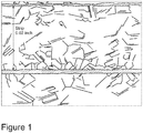
- Figure 1 is a magnified image of the microstructure of a Ni-Cr alloy strip made according to one embodiment of the present invention.
- an embodiment of the present invention includes an alloy that may be made using a roll compaction process.
- the alloy may comprise nickel and chromium having a combined wt. % of nickel and chromium of at least 97 wt. %, wherein the chromium accounts for 33 to 50 wt. % of the alloy, more preferably 35 to 50 wt. %, and most preferably 40 to 50 wt. %, and the alloy may comprise less than 3 wt. % of Mn and Si combined.
- the nickel content of the alloy may be at least 47 wt. %.
- the alloy may be provided in strip form having a tensile elongation of at least 30%.
- Another embodiment of the present invention includes an alloy comprising nickel and chromium having a combined wt. % of nickel and chromium of at least 99.8 wt. %, wherein the chromium accounts for 33 to 50 wt. % of the alloy, more preferably 35 to 50 wt. %, and most preferably 40 to 50 wt. %, and the alloy may exclude Mn and Si.
- the nickel content of the alloy may be at least 49.8 wt. %.
- a method of making an alloy strip comprises forming a powder charge, wherein the powder charge comprises 97 to 100 wt. % of nickel and chromium combined and the chromium accounts for 33 to 50 wt. % of the charge; roll compacting the powder charge to form a green strip; sintering the green strip to form a sintered strip; and cold rolling and annealing the sintered strip to form the alloy strip.
- the powder charge may be formed from at least one of a nickel containing powder and chromium containing powder that is at least 99.5% pure.
- a sheath for a flux cored welding electrode may be made by forming the sheath from an alloy made according to the present invention.
- Ni-Cr alloys As explained above, it is difficult to process Ni-Cr alloys into strip made by conventional means when the composition contains in excess of 33 wt. % chromium due to the presence of brittle phases.
- current practice within the welding consumables manufacturing industry for making products capable of depositing a weld bead or overlay with more than 33 wt. % chromium content is to use a strip as the consumable sheath that contains less than 33 wt. % chromium and add chromium to the flux core to provide the additionally required chromium to the product.
- the present invention eliminates or reduces the necessity of additional chromium to the flux core since the strip produced can contain in excess of 33 wt. % chromium and still exhibit sufficient ductility and formability to be successfully processed into sheaths for flux cored welding electrodes.
- Ni-Cr alloy strip having a chromium content which may be used in a welding consumable and have the ductility necessary to form the alloy into a sheath for a welding consumable
- a process has been discovered within the scope of the invention that is able to provide a formable Ni-Cr alloy containing chromium in excess of 33 wt. %, preferably 33 to 50 wt. % chromium, more preferably 35 to 50 wt. % chromium, and most preferably 40 to 50 wt. % chromium.
- % of the nickel and chromium in the alloy may be at least 97%, preferably at least 98%, more preferably at least 99%, and most preferably at least 99.8%.
- the resulting alloy has ductility characteristics which allow it to be drawn and formed into wire or sheaths for welding consumables.
- the Ni-Cr alloy according to the present invention has improved ductility and is not negatively affected by the brittle phases associated with higher chromium levels when compared to conventional Ni-Cr alloys having similar Cr content made using the casting process.
- strip includes all materials commonly known in the industry as sheet, strip, or foil that is less than 0.050 inches in thickness.
- sufficient ductility is the extent to which the alloy may be formed without fracture.
- the extent to which mechanically forming stresses an alloy sheet or strip when making a welding consumable is well-known in the art.
- the process of the present invention enables the production of a Ni-Cr alloy having a high chromium content and sufficient ductility to endure the forming processes associated with the production of welding consumables.
- "Sufficient ductility" as used herein is defined as tensile elongation as determined using ASTM E8, the standard test method for tension testing of metallic materials and is at least 30%, more preferably at least 40%.
- the present invention includes a process that eliminates melting. Because no melting is required to make the Ni-Cr alloy strip, there is no cast structure containing large grains of brittle phases even though the resulting strip will have a chromium content in excess of 33 wt. %.
- an additional advantage of the present invention is that since no melting takes place, there is no need to add extra elements to the composition to facilitate the melting process (such as deoxidants or fluidizers) and there will be little to no loss of volatile alloying elements as can occur during melting. Therefore, in one embodiment of the present invention, an alloy is provided consisting essentially of nickel and chromium having a combined wt. % of nickel and chromium of at least 97 wt. %, wherein the chromium accounts for 33 to 50 wt. % of the alloy.
- Nickel-based alloys made by conventional melting and hot & cold rolling techniques typically have a Mn and Si content in the 0.5 to 2.0% range.
- a Ni-Cr alloy is provided that is essentially void of Mn and Si.
- a Ni-Cr alloy is provided that may contain less than 3%, more preferably less than 1.5%, of Mn and Si combined.
- the Ni-Cr alloy of the invention may comprise essentially 0% of Mn and/or Si. As used herein, "essentially 0%" means less than 100 ppm.
- a process according to the present invention utilizes powder metallurgy, specifically roll compaction, and includes blending nickel and chromium containing powders in a ratio to make the desired Ni-Cr alloy composition, consolidating the powders into a green strip via roll compaction, sintering the green strip to increase its density and strength and homogenization of the alloying elements, followed by cold rolling and annealing the strip to a final thickness.
- a "green” strip as used herein throughout the specification and the claims means a metal strip produced by roll compaction which has not yet been treated to strengthen the material by sintering. Following roll compaction, the green strip may be sintered under an atmosphere containing hydrogen to improve the strength and reduce the oxygen content of the strip. The sintered strip may then be mechanically worked (cold rolling). As used herein throughout the specification and the claims, the term “cold rolling” means mechanically working the strip below the recrystallization temperature of the material.
- intermediate recrystallization anneals may be carried out as required between rolling cycles.
- the densification of the strip occurs during the sintering, cold rolling, and the recrystallization anneals.
- the final density of the material, or a value close to its theoretical density, is achieved after the cold rolling operations.
- nickel and chromium powder may be combined to form the desired alloy composition. It is preferred to use high purity metal powders that are 99.5% pure. As used herein, "99.5% pure" means at least 99.5 wt. % of the powder comprises nickel or chromium.
- the metal powders may include a suitable mixed nickel-chromium powder to which a high purity nickel or chromium powder may be added to achieve the desired final weight percent of nickel and chromium in the alloy.
- the powders should be well mixed to insure homogeneity of the powder charge. In order to obtain the desired powder properties for roll compaction, these properties being apparent density, flow, and consolidation characteristics, along with the properties of the resulting green strip, the average particle size of the powders should be less than about 100 microns.
- additives or binders which will preferably volatilize during subsequent processing, may be added to the powder charge to form a blend.
- these added components/additives would be dispersants, plasticizers, and sintering aids.
- Other known expedients may also be added for the purpose of altering the flow characteristics and the consolidation behavior of the powders in the blend.
- Suitable additives used for altering the characteristics of powders are well known in the art of powder metallurgy and include, for example, long chain fatty acids such as stearic acid, cellulose derivatives, organic colloids, salicylic acid, camphor, paraffin etc.
- the additives used in the blend should be kept at amounts lower than 2 wt % of the blend.
- the powder materials and additives may be combined using any suitable technique known in the art. For example, a V-cone blender may be used.
- the Ni-Cr alloy strip made according to various embodiments of the present invention may include up to 3 wt % of the nominal alloying elements.
- the material may then be roll compacted to form a green strip having a desired thickness.
- the powder material is preferably roll compacted by delivering the powder charge such that the powder cascades vertically between two horizontally opposed rolls with the powder fed into the roll nip in a uniform way.
- the density and dimensions of the green strip is determined primarily by the physical properties of the powder and spacing provided between the horizontally opposed rolls as well as the forces applied by the rolls.
- the preferred thickness of the green strip is 1,27mm to 5,08mm (0.050" to 0.200"), more preferably 1,52mm to 3,81mm (0.060" to 0.150"). Because the initial green strip is substantially thinner than the Ni-Cr ingots produced by conventional processes, embodiments of the present invention may require less work, and as a result, less processing time, to provide a strip having the desired thickness upon finishing. It is preferred that the resulting green strip has a density that is 50% to 90% of theoretical density, more preferably 60% to 90% of theoretical density.
- a green strip may be provided by roll compacting as described above and followed by sintering.
- Sintering requires heating the green strip under a controlled atmosphere for a period of time.
- the sintering process reduces the oxygen content of the strip as well as provides inter-particle bonding and an increase in density, so that the strength of the resulting strip is significantly increased.
- Sintering may also occur under vacuum or partial pressure of an inert gas or more preferably under partial pressure of hydrogen.
- Sintering occurs at temperatures of 1000 °C to 1350 °C, more preferably from 1100 °C to 1350 °C, most preferably from 1150 °C to 1250 °C.
- the sintering process may last from 1 to 12 hours when higher temperatures are used and 12 to 48 hours at the lower sintering temperatures.
- embodiments of the present invention include a process comprising a combination of cold rolling and annealing the sintered strip to form the final strip.
- the cold rolling steps occurs at room temperature. It is also preferred that cold rolling occurs under conditions which minimize oxidation of the sintered strip. Because the temperatures are generally low enough that oxidation is not a concern, cold rolling may occur under an oxygen containing atmosphere, such as air.
- Cold rolling comprises working the material in order to reduce the strip's thickness.
- the strip may be passed one or more times through a rolling process.
- the strip thickness may be reduced 1% to 30% per pass, preferably 5% to 20% per pass, by cold rolling.
- the total reduction per rolling cycle is preferably 20% to 50%, more preferably 30% to 40%.
- Embodiments of the present inventive method may also include recrystallization annealing steps. Recrystallization annealing is carried out at a temperature above the recrystallization temperature of the material in order to reduce its strength and hardness and is accompanied by changes in the microstructure. According to various embodiments of the present invention, the recrystallization anneal occurs at a temperature from 1038 °C to 1260 °C (1900 °F to 2300 °F). The total time required for a recrystallization anneal may be shorter if higher temperatures are used. Similar to sintering, annealing preferably occurs under a gaseous atmosphere comprising hydrogen and/or under partial pressure of hydrogen, or the recrystallization annealing may occur under vacuum or inert gas.
- Embodiments of the present invention may include a plurality of cold rolling cycles with annealing steps occurring between each cold rolling cycle. Again, each cold rolling cycle may include multiple passes. Following the final cold rolling cycle, the Ni-Cr alloy strip has a thickness that is preferably 35% or less of the thickness of the original green strip, i.e. reduction of a green strip according to an embodiment of the present invention may require about 65% reduction or more to reach the target thickness.
- Powders containing 1,474 grams of nickel, 794 grams of chromium, and 39 grams of Fe-Si alloy were blended together in a V-cone blender. The blend was fed vertically down into a roll compaction mill to produce a green strip. The resulting green strip was sintered in a hydrogen atmosphere furnace at 1204°C (2200 °F). The strip thickness at this point was 2,44mm (0.096"). The nominal composition of the sintered strip was 63.9% Ni, 34.4% Cr, 0.4 Fe%, and 1.3% Si (wt. percents).
- the strip was subsequently rolled from 2,44 mm (0.096”) to 1,27mm (0.050”), then from 1,27mm (0.050") to 0,762mm (0.030”), and finally from 0,762mm (0.030") to 0,508mm (0.020") with intermediate anneals at 1038°C (1900 °F) for 10 minutes.
- the final 0,508mm (0.020") thick strip was slit to have a width of 12,7mm (0.500”), annealed at 1149°C (2100 °F), and tested for its mechanical properties using standard ASTM E8 test procedures.
- the measured values for the mechanical properties were the following: Yield Strength: 174,4 MPa (25.3 ksi) Ultimate Tensile Strength: 573,6 MPa (83.2 ksi) % Elongation: 46.6
- FIG. 1 A magnified image of the microstructure of the strip made in Example 1 is provided as Figure 1 .
- Powders containing 1361 grams of nickel, 907 grams of chromium, and 39 grams of Fe-Si alloy were blended together in a V-cone blender. The blend was fed vertically down into a roll compaction mill to produce a green strip. The resulting green strip was sintered in a hydrogen atmosphere furnace at temperature of 1204°C (2200 °F). The strip thickness at this point was 2,74mm (0.108") thick. The nominal composition of the sintered strip was 59.0% Ni, 39.3% Cr, 0.4% Fe, and 1.3% Si (wt. percents).
- the strip was rolled from 2,74mm (0.108”) to 1,27mm (0.050”), from 1,27mm (0.050”) to 0,762 (0.030”), and finally from 0,762mm (0.030") to 0,508mm (0.020") with intermediate anneals at 1038°C (1900 °F) for 10 minutes.
- the final 0,508mm (0.020") thick strip was slit to have a width of 12,7mm (0.500”), annealed at 1149°C (2100 °F), and tested for its mechanical properties using standard ASTM E8 test procedures.
- the measured values for the mechanical properties were as follows: Yield Strength: 316,5MPa (45.9 ksi) Ultimate Tensile Strength: 697,7 MPa (101.2 ksi) % Elongation: 42.8
Landscapes
- Chemical & Material Sciences (AREA)
- Engineering & Computer Science (AREA)
- Mechanical Engineering (AREA)
- Materials Engineering (AREA)
- Metallurgy (AREA)
- Organic Chemistry (AREA)
- Manufacturing & Machinery (AREA)
- Physics & Mathematics (AREA)
- Thermal Sciences (AREA)
- Crystallography & Structural Chemistry (AREA)
- Powder Metallurgy (AREA)
Description
- The invention relates to nickel-chromium alloys and methods of making nickel-chromium alloys having improved ductility that may be provided in strip form. The strip may be used in a variety of applications including the manufacture of sheaths for flux cored welding electrodes.
- Ni-Cr alloys are used in many applications requiring high temperature oxidation and corrosion resistance. Ni-Cr alloys, with high chromium content (35%-60%) are used in cast form for applications in power plants and boilers where resistance to fuels, ashes, and deposits high in sulfur and vanadium content is required. Various alloys in strip form are widely used in many diverse applications, including the manufacture of welding consumables which can also be used for overlay coatings.
- Conventional means of producing Ni-Cr alloy strip typically include adding nickel- and chromium-containing melt stocks into a suitable melting furnace (along with any desired alloying elements and other elements required to deoxidize and fluidize the melt), melting the charge, and casting it into an ingot. This ingot may then be processed by hot and cold working into strip, or may be re-melted to purify the composition and refine the cast grain structure prior to being hot and cold worked into strip. This strip may then be used as the outer sheath of a flux cored welding consumable, and as such its chemical composition needs to be tightly controlled because the elements contained in the strip will be incorporated into the weld bead or overlay when the welding consumable is subsequently used.
-
WO 2008/064214 A1 for example discloses an alloy for use as a welding overlay for boiler tubes in a low NOx coal-fired boiler comprising in % by weight: 36 to 43% Cr, 0.2 to 5.0% Fe, 0-2.0% Nb, 0-1% Mo, 0.3 to 1% Ti, 0.5 to 2% Al, 0.005 to 0.05% C, 0.005 to 0.020% (Mg + Ca), 0-1% Mn, 0-0.5% Si, less than 0.01% S, balance substantially Ni and trace additions and impurities. The alloy provides exceptional coal ash corrosion resistance in low partial pressures of oxygen. The alloy also increases in hardness and in thermal conductivity at service temperature over time. The increased hardness improves erosion resistance of the tubes while the increased thermal conductivity improves the thermal efficiency of the boiler and its power generation capabilities. -
WO 2013/182178 A1 discloses a nickel-chromium alloy comprising (in wt.-%) 29 to 37% chromium, 0.001 to 1.8% aluminum, 0.10 to 7.0% iron, 0.001 to 0.50% silicon, 0.005 to 2.0% manganese, 0.00 to 1.00% titanium and/or 0.00 to 1.10% niobium, 0.0002 to 0.05% each of magnesium and/or calcium, 0.005 to 12% carbon, 0.001 to 0.050% nitrogen, 0.001 to 0.030% phosphorus, 0.0001 to 0.020% oxygen, not more than 0.010% sulfur, not more than 2.0% molybdenum, not more than 2.0% tungsten, the remainder nickel and the usual process-related impurities, wherein the following relations must be satisfied: Cr + Al >= 30 (2a) and Fp <= 39.9 (3a) with Fp = Cr + 0.272*Fe + 2.36*Al + 2.22*Si + 2.48*Ti + 0.374*Mo + 0,538*W - 11.8*C (4a), wherein Cr, Fe, Al, Si, Ti, Mo, W and C is the concentration of the respective elements in % by mass. - In general, Ni-Cr alloys, with high Cr content (greater than 30%) made by conventional means (melting and casting) are difficult to work and therefore generally not processed into strip form. The ductility of the Ni-Cr alloy is inversely proportional to the concentration of chromium because the chromium has a phase structure which is brittle. Ni-Cr alloys having a chromium content greater than 30% are generally only suited to casting. This occurs because segregation during the casting process results in the formation of large volumes of the brittle phases of chromium within the cast structure of the ingot and reduces the ductility of the alloy to the point where the alloy does not have sufficient ductility for working the cast ingot into a strip useable as a sheath in a flux cored welding electrode.
- In contrast, welding consumable manufacturers desire to make products containing high chromium levels because these high chromium materials can produce weld beads or overlays that exhibit enhanced corrosion resistance and wear resistance. Thus, a cheaper base material can be overlaid with a layer of high chromium Ni-Cr alloy so that it will have sufficient corrosion or wear resistance in service. Because of the embrittlement problem with high chromium content Ni-Cr alloys, when a welding consumable manufacturer wishes to produce a product that is able to deposit a weld bead or overlay of Ni-Cr composition in excess of 33 weight percent (wt. %) chromium, the only means possible is to use commercially available strip for the weld wire sheath with lower than 33 wt. % chromium content and add the extra required chromium by blending chromium powder or a chromium alloy powder with the other constituents that are contained within the core of the welding wire. This, of course, adds costs to the manufacture of the welding consumable.
- There is therefore a need to provide a method of making a Ni-Cr alloy strip containing chromium in excess of 33 wt. % chromium balance nickel in strip form having adequate ductility and formability, so that it can be used as the sheath in flux cored welding consumables. This would reduce or eliminate the need to make chromium additions to the core of the welding wire, thereby lowering the cost of making such wire.
- The above objects are solved by the claimed subject matter according to the independent claim.
- One aspect of the present invention is to provide a method of making an alloy strip comprising forming a powder charge; roll compacting the powder charge to form a green strip; sintering the green strip to form a sintered strip; and cold rolling and annealing the sintered strip to form the alloy strip.
-
Figure 1 is a magnified image of the microstructure of a Ni-Cr alloy strip made according to one embodiment of the present invention. - Generally, an embodiment of the present invention includes an alloy that may be made using a roll compaction process. The alloy may comprise nickel and chromium having a combined wt. % of nickel and chromium of at least 97 wt. %, wherein the chromium accounts for 33 to 50 wt. % of the alloy, more preferably 35 to 50 wt. %, and most preferably 40 to 50 wt. %, and the alloy may comprise less than 3 wt. % of Mn and Si combined. In certain embodiments, the nickel content of the alloy may be at least 47 wt. %. The alloy may be provided in strip form having a tensile elongation of at least 30%.
- Another embodiment of the present invention includes an alloy comprising nickel and chromium having a combined wt. % of nickel and chromium of at least 99.8 wt. %, wherein the chromium accounts for 33 to 50 wt. % of the alloy, more preferably 35 to 50 wt. %, and most preferably 40 to 50 wt. %, and the alloy may exclude Mn and Si. In certain embodiments, the nickel content of the alloy may be at least 49.8 wt. %.
- In yet another embodiment of the present invention, a method of making an alloy strip comprises forming a powder charge, wherein the powder charge comprises 97 to 100 wt. % of nickel and chromium combined and the chromium accounts for 33 to 50 wt. % of the charge; roll compacting the powder charge to form a green strip; sintering the green strip to form a sintered strip; and cold rolling and annealing the sintered strip to form the alloy strip. The powder charge may be formed from at least one of a nickel containing powder and chromium containing powder that is at least 99.5% pure. In certain embodiments, a sheath for a flux cored welding electrode may be made by forming the sheath from an alloy made according to the present invention.
- As explained above, it is difficult to process Ni-Cr alloys into strip made by conventional means when the composition contains in excess of 33 wt. % chromium due to the presence of brittle phases. In light of this, current practice within the welding consumables manufacturing industry for making products capable of depositing a weld bead or overlay with more than 33 wt. % chromium content is to use a strip as the consumable sheath that contains less than 33 wt. % chromium and add chromium to the flux core to provide the additionally required chromium to the product. The present invention eliminates or reduces the necessity of additional chromium to the flux core since the strip produced can contain in excess of 33 wt. % chromium and still exhibit sufficient ductility and formability to be successfully processed into sheaths for flux cored welding electrodes.
- To manufacture a Ni-Cr alloy strip having a chromium content which may be used in a welding consumable and have the ductility necessary to form the alloy into a sheath for a welding consumable, a process has been discovered within the scope of the invention that is able to provide a formable Ni-Cr alloy containing chromium in excess of 33 wt. %, preferably 33 to 50 wt. % chromium, more preferably 35 to 50 wt. % chromium, and most preferably 40 to 50 wt. % chromium. The combined wt. % of the nickel and chromium in the alloy may be at least 97%, preferably at least 98%, more preferably at least 99%, and most preferably at least 99.8%. The resulting alloy has ductility characteristics which allow it to be drawn and formed into wire or sheaths for welding consumables. The Ni-Cr alloy according to the present invention has improved ductility and is not negatively affected by the brittle phases associated with higher chromium levels when compared to conventional Ni-Cr alloys having similar Cr content made using the casting process.
- As used herein throughout the specification and the claims, the term "strip" includes all materials commonly known in the industry as sheet, strip, or foil that is less than 0.050 inches in thickness.
- Preferably, "sufficient ductility" is the extent to which the alloy may be formed without fracture. The extent to which mechanically forming stresses an alloy sheet or strip when making a welding consumable is well-known in the art. Thus, the process of the present invention enables the production of a Ni-Cr alloy having a high chromium content and sufficient ductility to endure the forming processes associated with the production of welding consumables. "Sufficient ductility" as used herein is defined as tensile elongation as determined using ASTM E8, the standard test method for tension testing of metallic materials and is at least 30%, more preferably at least 40%.
- To manufacture a Ni-Cr alloy strip with a chromium content in excess of 33 wt. %, more preferably in excess of 35 wt. %, and most preferably in excess of 40 wt. %, that has sufficient ductility, so that it may be formed into a flux cored welding consumable, the present invention includes a process that eliminates melting. Because no melting is required to make the Ni-Cr alloy strip, there is no cast structure containing large grains of brittle phases even though the resulting strip will have a chromium content in excess of 33 wt. %.
- An additional advantage of the present invention is that since no melting takes place, there is no need to add extra elements to the composition to facilitate the melting process (such as deoxidants or fluidizers) and there will be little to no loss of volatile alloying elements as can occur during melting. Therefore, in one embodiment of the present invention, an alloy is provided consisting essentially of nickel and chromium having a combined wt. % of nickel and chromium of at least 97 wt. %, wherein the chromium accounts for 33 to 50 wt. % of the alloy. Additional alloying elements other than nickel and chromium may be present in the alloy, for example, in trace amounts, but the additional alloying elements are not needed to obtain a strip of the alloy having a tensile elongation of at least 30%. Nickel-based alloys made by conventional melting and hot & cold rolling techniques typically have a Mn and Si content in the 0.5 to 2.0% range. In certain embodiments of the present invention, a Ni-Cr alloy is provided that is essentially void of Mn and Si. In a preferred embodiment of the invention, a Ni-Cr alloy is provided that may contain less than 3%, more preferably less than 1.5%, of Mn and Si combined. In some embodiments, the Ni-Cr alloy of the invention may comprise essentially 0% of Mn and/or Si. As used herein, "essentially 0%" means less than 100 ppm.
- A process according to the present invention utilizes powder metallurgy, specifically roll compaction, and includes blending nickel and chromium containing powders in a ratio to make the desired Ni-Cr alloy composition, consolidating the powders into a green strip via roll compaction, sintering the green strip to increase its density and strength and homogenization of the alloying elements, followed by cold rolling and annealing the strip to a final thickness.
- A "green" strip as used herein throughout the specification and the claims means a metal strip produced by roll compaction which has not yet been treated to strengthen the material by sintering. Following roll compaction, the green strip may be sintered under an atmosphere containing hydrogen to improve the strength and reduce the oxygen content of the strip. The sintered strip may then be mechanically worked (cold rolling). As used herein throughout the specification and the claims, the term "cold rolling" means mechanically working the strip below the recrystallization temperature of the material.
- According to various embodiments of the invention, intermediate recrystallization anneals may be carried out as required between rolling cycles. The densification of the strip occurs during the sintering, cold rolling, and the recrystallization anneals. The final density of the material, or a value close to its theoretical density, is achieved after the cold rolling operations.
- In one embodiment of the present invention, nickel and chromium powder may be combined to form the desired alloy composition. It is preferred to use high purity metal powders that are 99.5% pure. As used herein, "99.5% pure" means at least 99.5 wt. % of the powder comprises nickel or chromium. In another embodiment, the metal powders may include a suitable mixed nickel-chromium powder to which a high purity nickel or chromium powder may be added to achieve the desired final weight percent of nickel and chromium in the alloy. When using powders of different constituents, the powders should be well mixed to insure homogeneity of the powder charge. In order to obtain the desired powder properties for roll compaction, these properties being apparent density, flow, and consolidation characteristics, along with the properties of the resulting green strip, the average particle size of the powders should be less than about 100 microns.
- Other components known in the industry as additives or binders, which will preferably volatilize during subsequent processing, may be added to the powder charge to form a blend. Examples of these added components/additives would be dispersants, plasticizers, and sintering aids. Other known expedients may also be added for the purpose of altering the flow characteristics and the consolidation behavior of the powders in the blend. Suitable additives used for altering the characteristics of powders are well known in the art of powder metallurgy and include, for example, long chain fatty acids such as stearic acid, cellulose derivatives, organic colloids, salicylic acid, camphor, paraffin etc. Preferably, the additives used in the blend should be kept at amounts lower than 2 wt % of the blend. The powder materials and additives may be combined using any suitable technique known in the art. For example, a V-cone blender may be used.
- Additional nominal alloying elements for the Ni-Cr alloys according to the present invention may be selected and incorporated based on the desired properties of the final strip, such as the mechanical properties, e.g. yield strength, ultimate tensile strength, and % elongation, etc. When incorporating nominal alloying elements, the Ni-Cr alloy strip made according to various embodiments of the present invention may include up to 3 wt % of the nominal alloying elements.
- Upon adding any additives to obtain a powder blend, the material may then be roll compacted to form a green strip having a desired thickness. The powder material is preferably roll compacted by delivering the powder charge such that the powder cascades vertically between two horizontally opposed rolls with the powder fed into the roll nip in a uniform way.
- The density and dimensions of the green strip is determined primarily by the physical properties of the powder and spacing provided between the horizontally opposed rolls as well as the forces applied by the rolls. The preferred thickness of the green strip is 1,27mm to 5,08mm (0.050" to 0.200"), more preferably 1,52mm to 3,81mm (0.060" to 0.150"). Because the initial green strip is substantially thinner than the Ni-Cr ingots produced by conventional processes, embodiments of the present invention may require less work, and as a result, less processing time, to provide a strip having the desired thickness upon finishing. It is preferred that the resulting green strip has a density that is 50% to 90% of theoretical density, more preferably 60% to 90% of theoretical density.
- According to an embodiment of the present invention, a green strip may be provided by roll compacting as described above and followed by sintering. Sintering requires heating the green strip under a controlled atmosphere for a period of time. The sintering process reduces the oxygen content of the strip as well as provides inter-particle bonding and an increase in density, so that the strength of the resulting strip is significantly increased. It is preferred that sintering occur under a gaseous atmosphere comprising at least 10% hydrogen, more preferably 25% to 100% of hydrogen. Sintering may also occur under vacuum or partial pressure of an inert gas or more preferably under partial pressure of hydrogen. Sintering occurs at temperatures of 1000 °C to 1350 °C, more preferably from 1100 °C to 1350 °C, most preferably from 1150 °C to 1250 °C. The sintering process may last from 1 to 12 hours when higher temperatures are used and 12 to 48 hours at the lower sintering temperatures.
- In order to further reduce the thickness of the sintered strip to a lighter gauge material, embodiments of the present invention include a process comprising a combination of cold rolling and annealing the sintered strip to form the final strip. In embodiments of the present inventive method, it is preferred that the cold rolling steps occurs at room temperature. It is also preferred that cold rolling occurs under conditions which minimize oxidation of the sintered strip. Because the temperatures are generally low enough that oxidation is not a concern, cold rolling may occur under an oxygen containing atmosphere, such as air.
- Cold rolling comprises working the material in order to reduce the strip's thickness. The strip may be passed one or more times through a rolling process. The total number of passes constituting one cold rolling cycle. According to an embodiment of the present invention, the strip thickness may be reduced 1% to 30% per pass, preferably 5% to 20% per pass, by cold rolling. The total reduction per rolling cycle is preferably 20% to 50%, more preferably 30% to 40%.
- Embodiments of the present inventive method may also include recrystallization annealing steps. Recrystallization annealing is carried out at a temperature above the recrystallization temperature of the material in order to reduce its strength and hardness and is accompanied by changes in the microstructure. According to various embodiments of the present invention, the recrystallization anneal occurs at a temperature from 1038 °C to 1260 °C (1900 °F to 2300 °F). The total time required for a recrystallization anneal may be shorter if higher temperatures are used. Similar to sintering, annealing preferably occurs under a gaseous atmosphere comprising hydrogen and/or under partial pressure of hydrogen, or the recrystallization annealing may occur under vacuum or inert gas.
- Embodiments of the present invention may include a plurality of cold rolling cycles with annealing steps occurring between each cold rolling cycle. Again, each cold rolling cycle may include multiple passes. Following the final cold rolling cycle, the Ni-Cr alloy strip has a thickness that is preferably 35% or less of the thickness of the original green strip, i.e. reduction of a green strip according to an embodiment of the present invention may require about 65% reduction or more to reach the target thickness.
- In order that the invention may be more fully understood the following Examples are provided by way of illustration only.
- Powders containing 1,474 grams of nickel, 794 grams of chromium, and 39 grams of Fe-Si alloy were blended together in a V-cone blender. The blend was fed vertically down into a roll compaction mill to produce a green strip. The resulting green strip was sintered in a hydrogen atmosphere furnace at 1204°C (2200 °F). The strip thickness at this point was 2,44mm (0.096"). The nominal composition of the sintered strip was 63.9% Ni, 34.4% Cr, 0.4 Fe%, and 1.3% Si (wt. percents).
- The strip was subsequently rolled from 2,44 mm (0.096") to 1,27mm (0.050"), then from 1,27mm (0.050") to 0,762mm (0.030"), and finally from 0,762mm (0.030") to 0,508mm (0.020") with intermediate anneals at 1038°C (1900 °F) for 10 minutes. The final 0,508mm (0.020") thick strip was slit to have a width of 12,7mm (0.500"), annealed at 1149°C (2100 °F), and tested for its mechanical properties using standard ASTM E8 test procedures. The measured values for the mechanical properties were the following:
Yield Strength: 174,4 MPa (25.3 ksi) Ultimate Tensile Strength: 573,6 MPa (83.2 ksi) % Elongation: 46.6 - A magnified image of the microstructure of the strip made in Example 1 is provided as
Figure 1 . - Powders containing 1361 grams of nickel, 907 grams of chromium, and 39 grams of Fe-Si alloy were blended together in a V-cone blender. The blend was fed vertically down into a roll compaction mill to produce a green strip. The resulting green strip was sintered in a hydrogen atmosphere furnace at temperature of 1204°C (2200 °F). The strip thickness at this point was 2,74mm (0.108") thick. The nominal composition of the sintered strip was 59.0% Ni, 39.3% Cr, 0.4% Fe, and 1.3% Si (wt. percents).
- The strip was rolled from 2,74mm (0.108") to 1,27mm (0.050"), from 1,27mm (0.050") to 0,762 (0.030"), and finally from 0,762mm (0.030") to 0,508mm (0.020") with intermediate anneals at 1038°C (1900 °F) for 10 minutes. The final 0,508mm (0.020") thick strip was slit to have a width of 12,7mm (0.500"), annealed at 1149°C (2100 °F), and tested for its mechanical properties using standard ASTM E8 test procedures. The measured values for the mechanical properties were as follows:
Yield Strength: 316,5MPa (45.9 ksi) Ultimate Tensile Strength: 697,7 MPa (101.2 ksi) % Elongation: 42.8 - While preferred embodiments of the invention have been shown and described herein, it will be understood that such embodiments are provided by way of example only. Numerous variations, changes, and substitutions may occur to those skilled in the art without departing from the spirit of the invention. Accordingly, it is intended that the appended claims cover all such variations that fall within the spirit and scope of the invention.
Claims (11)
- A method of making an alloy strip comprising:forming a powder charge comprising nickel and chromium;roll compacting the powder charge to form a green strip;sintering the green strip to form a sintered strip; andcold rolling and annealing the sintered strip to form the alloy strip,wherein the alloy strip consists of 33 to 50 wt. % of chromium, optionally up to 3 wt. % of either Mn or Si, with the balance being nickel and incidental trace alloying elements, andwherein the alloy strip has a tensile elongation of at least 30%.
- The method of claim 1, wherein the powder charge is formed from at least one of a nickel containing powder and chromium containing powder that is at least 99.5% pure.
- The method of claim 1, wherein the powder charge is formed from at least one of a nickel containing powder and chromium containing powder that is at least 99.8% pure.
- The method of claim 1, wherein the combined wt. % of nickel and chromium of the alloy strip is at least 97 wt. %.
- The method of claim 1, wherein the chromium accounts for 35 to 50 wt. % of the alloy strip.
- The method of claim 1, wherein the chromium accounts for 40 to 50 wt. % of the alloy strip.
- The method of claim 1, wherein the combined wt. % of Mn and Si of the alloy strip is less than 3 wt. %.
- The method of claim 1, wherein the nickel accounts for at least 47 wt. % of the alloy strip.
- The method of claim 1, wherein the combined wt. % of nickel and chromium of the alloy strip is at least 99.8 wt. %.
- The method of claim 1, wherein the combined wt. % of Mn and Si of the alloy strip is essentially 0%.
- The method of claim 1, wherein the nickel accounts for at least 49.8 wt. % of the alloy strip.
Priority Applications (1)
| Application Number | Priority Date | Filing Date | Title |
|---|---|---|---|
| EP19178899.1A EP3563948A1 (en) | 2014-09-05 | 2015-09-04 | Nickel-chromium alloy and method of making the same |
Applications Claiming Priority (1)
| Application Number | Priority Date | Filing Date | Title |
|---|---|---|---|
| US14/478,231 US11130201B2 (en) | 2014-09-05 | 2014-09-05 | Nickel-chromium alloy and method of making the same |
Related Child Applications (2)
| Application Number | Title | Priority Date | Filing Date |
|---|---|---|---|
| EP19178899.1A Division-Into EP3563948A1 (en) | 2014-09-05 | 2015-09-04 | Nickel-chromium alloy and method of making the same |
| EP19178899.1A Division EP3563948A1 (en) | 2014-09-05 | 2015-09-04 | Nickel-chromium alloy and method of making the same |
Publications (2)
| Publication Number | Publication Date |
|---|---|
| EP2992985A1 EP2992985A1 (en) | 2016-03-09 |
| EP2992985B1 true EP2992985B1 (en) | 2019-10-23 |
Family
ID=54065737
Family Applications (2)
| Application Number | Title | Priority Date | Filing Date |
|---|---|---|---|
| EP15183897.6A Active EP2992985B1 (en) | 2014-09-05 | 2015-09-04 | Nickel-chromium alloy and method of making the same |
| EP19178899.1A Pending EP3563948A1 (en) | 2014-09-05 | 2015-09-04 | Nickel-chromium alloy and method of making the same |
Family Applications After (1)
| Application Number | Title | Priority Date | Filing Date |
|---|---|---|---|
| EP19178899.1A Pending EP3563948A1 (en) | 2014-09-05 | 2015-09-04 | Nickel-chromium alloy and method of making the same |
Country Status (3)
| Country | Link |
|---|---|
| US (2) | US11130201B2 (en) |
| EP (2) | EP2992985B1 (en) |
| CN (1) | CN105420553B (en) |
Families Citing this family (1)
| Publication number | Priority date | Publication date | Assignee | Title |
|---|---|---|---|---|
| US11130201B2 (en) * | 2014-09-05 | 2021-09-28 | Ametek, Inc. | Nickel-chromium alloy and method of making the same |
Family Cites Families (27)
| Publication number | Priority date | Publication date | Assignee | Title |
|---|---|---|---|---|
| US2023818A (en) | 1932-08-09 | 1935-12-10 | Meaf Mach En Apparaten Fab Nv | Coated steel electrode for arc welding |
| US2990301A (en) | 1957-10-23 | 1961-06-27 | Air Reduction | Arc welding electrode |
| US3113021A (en) | 1961-02-13 | 1963-12-03 | Int Nickel Co | Filler wire for shielded arc welding |
| GB1184656A (en) | 1966-06-17 | 1970-03-18 | Johnson Matthey Co Ltd | Improvements in and relating to Self Regulating Heating Elements. |
| US3519419A (en) * | 1966-06-21 | 1970-07-07 | Int Nickel Co | Superplastic nickel alloys |
| US3848109A (en) * | 1971-03-01 | 1974-11-12 | Stoody Co | Arc welding process and electrode for stainless steel |
| US3984239A (en) | 1975-04-07 | 1976-10-05 | The International Nickel Company, Inc. | Filler metal |
| GB1559690A (en) | 1976-11-10 | 1980-01-23 | British Steel Corp | Treatment of steel products |
| US4158719A (en) * | 1977-06-09 | 1979-06-19 | Carpenter Technology Corporation | Low expansion low resistivity composite powder metallurgy member and method of making the same |
| US4373970A (en) * | 1981-11-13 | 1983-02-15 | Pfizer Inc. | Copper base spinodal alloy strip and process for its preparation |
| US5474737A (en) * | 1993-07-01 | 1995-12-12 | The United States Of America As Represented By The Secretary Of Commerce | Alloys for cryogenic service |
| JPH0952194A (en) | 1995-08-11 | 1997-02-25 | Kubota Corp | Welding method of high chromium nikkel alloy member |
| US5686676A (en) * | 1996-05-07 | 1997-11-11 | Brush Wellman Inc. | Process for making improved copper/tungsten composites |
| JPH11285890A (en) | 1998-04-02 | 1999-10-19 | Kubota Corp | High c/high cr-ni based welding rod |
| US6242113B1 (en) | 1999-06-10 | 2001-06-05 | Inco Alloys International, Inc. | Welding alloy and articles for use in welding, weldments and methods for producing weldments |
| US20050000603A1 (en) * | 2003-06-25 | 2005-01-06 | John Corrigan | Nickel base superalloy and single crystal castings |
| US20050183797A1 (en) * | 2004-02-23 | 2005-08-25 | Ranjan Ray | Fine grained sputtering targets of cobalt and nickel base alloys made via casting in metal molds followed by hot forging and annealing and methods of making same |
| CN101979210B (en) | 2005-01-25 | 2012-11-21 | 亨廷顿合金公司 | Method for generating a weld deposit |
| US8568901B2 (en) | 2006-11-21 | 2013-10-29 | Huntington Alloys Corporation | Filler metal composition and method for overlaying low NOx power boiler tubes |
| US20110100970A1 (en) | 2009-11-03 | 2011-05-05 | Lincoln Global, Inc. | Manufacture of cored welding electrodes |
| EP2531632A2 (en) | 2010-02-01 | 2012-12-12 | Crucible Intellectual Property, LLC | Nickel based thermal spray powder and coating, and method for making the same |
| CN103635284B (en) * | 2011-03-23 | 2017-03-29 | 思高博塔公司 | The particulate nickel-base alloy split for stress corrosion resistant and its method for designing |
| JP5977998B2 (en) | 2012-05-15 | 2016-08-24 | 株式会社神戸製鋼所 | Ni-base alloy weld metal, strip electrode, and welding method |
| DE102012011162B4 (en) | 2012-06-05 | 2014-05-22 | Outokumpu Vdm Gmbh | Nickel-chromium alloy with good processability, creep resistance and corrosion resistance |
| US20140261905A1 (en) * | 2013-03-15 | 2014-09-18 | Castrip, Llc | Method of thin strip casting |
| US9238852B2 (en) * | 2013-09-13 | 2016-01-19 | Ametek, Inc. | Process for making molybdenum or molybdenum-containing strip |
| US11130201B2 (en) * | 2014-09-05 | 2021-09-28 | Ametek, Inc. | Nickel-chromium alloy and method of making the same |
-
2014
- 2014-09-05 US US14/478,231 patent/US11130201B2/en active Active
-
2015
- 2015-09-04 EP EP15183897.6A patent/EP2992985B1/en active Active
- 2015-09-04 EP EP19178899.1A patent/EP3563948A1/en active Pending
- 2015-09-07 CN CN201510742497.9A patent/CN105420553B/en active Active
-
2021
- 2021-09-08 US US17/469,368 patent/US20210402524A1/en active Pending
Non-Patent Citations (1)
| Title |
|---|
| None * |
Also Published As
| Publication number | Publication date |
|---|---|
| US20160067834A1 (en) | 2016-03-10 |
| CN105420553B (en) | 2019-08-23 |
| US20210402524A1 (en) | 2021-12-30 |
| US11130201B2 (en) | 2021-09-28 |
| EP3563948A1 (en) | 2019-11-06 |
| CN105420553A (en) | 2016-03-23 |
| EP2992985A1 (en) | 2016-03-09 |
Similar Documents
| Publication | Publication Date | Title |
|---|---|---|
| CN106062235B (en) | The method for being used to prepare molybdenum or the band containing molybdenum | |
| CN106048309B (en) | The manufacture method of Ni based heat resistant alloy welding points and the welding point obtained using it | |
| CN108118193B (en) | Method for producing Ni-based superalloy material | |
| EP2418295A1 (en) | Low thermal expansion Ni-base superalloy | |
| JP2004323937A (en) | Austenitic stainless steel | |
| JP5596697B2 (en) | Aluminum oxide forming nickel base alloy | |
| KR20120137520A (en) | Austenitic stainless steel | |
| CN108118192B (en) | Method for producing Ni-based superalloy material | |
| KR20100059957A (en) | Austenitic stainless steel | |
| CN106062230A (en) | Austenitic heat-resistant alloy | |
| JPH0118979B2 (en) | ||
| JP2009185352A (en) | Ni-BASED ALLOY MATERIAL HAVING COLD STRENGTH AND WORKABILITY AND CREEP PROPERTY AND METHOD FOR PRODUCING THE SAME | |
| US9969004B2 (en) | α+β or β titanium alloy and method for producing same | |
| JP4074555B2 (en) | Manufacturing method of steel for high strength low alloy boilers with excellent creep characteristics | |
| JPWO2014126086A1 (en) | Metal powder, hot working tool, and method of manufacturing hot working tool | |
| US20210402524A1 (en) | Nickel-chromium alloy and method of making the same | |
| KR101387551B1 (en) | High strength titanium alloy with excellent oxidation resistance and formability and method for manufacturing the same | |
| WO2011125663A1 (en) | Molybdenum alloy and process for producing same | |
| US4370299A (en) | Molybdenum-based alloy | |
| JP6747207B2 (en) | Ni-based heat-resistant alloy member | |
| JPS5935642A (en) | Production of mo alloy ingot | |
| JP5026686B2 (en) | Ni-base alloy material excellent in workability and high-temperature strength and method for producing the same | |
| WO2024123229A1 (en) | Nickel-based alloy | |
| CN117418153A (en) | Nickel-based high-temperature alloy foil with stable long-term structure and preparation method and application thereof | |
| CN115461477A (en) | Method for producing austenitic heat-resistant steel |
Legal Events
| Date | Code | Title | Description |
|---|---|---|---|
| PUAI | Public reference made under article 153(3) epc to a published international application that has entered the european phase |
Free format text: ORIGINAL CODE: 0009012 |
|
| AK | Designated contracting states |
Kind code of ref document: A1 Designated state(s): AL AT BE BG CH CY CZ DE DK EE ES FI FR GB GR HR HU IE IS IT LI LT LU LV MC MK MT NL NO PL PT RO RS SE SI SK SM TR |
|
| AX | Request for extension of the european patent |
Extension state: BA ME |
|
| 17P | Request for examination filed |
Effective date: 20160909 |
|
| RBV | Designated contracting states (corrected) |
Designated state(s): AL AT BE BG CH CY CZ DE DK EE ES FI FR GB GR HR HU IE IS IT LI LT LU LV MC MK MT NL NO PL PT RO RS SE SI SK SM TR |
|
| STAA | Information on the status of an ep patent application or granted ep patent |
Free format text: STATUS: EXAMINATION IS IN PROGRESS |
|
| 17Q | First examination report despatched |
Effective date: 20170425 |
|
| GRAP | Despatch of communication of intention to grant a patent |
Free format text: ORIGINAL CODE: EPIDOSNIGR1 |
|
| STAA | Information on the status of an ep patent application or granted ep patent |
Free format text: STATUS: GRANT OF PATENT IS INTENDED |
|
| INTG | Intention to grant announced |
Effective date: 20190403 |
|
| GRAS | Grant fee paid |
Free format text: ORIGINAL CODE: EPIDOSNIGR3 |
|
| GRAA | (expected) grant |
Free format text: ORIGINAL CODE: 0009210 |
|
| STAA | Information on the status of an ep patent application or granted ep patent |
Free format text: STATUS: THE PATENT HAS BEEN GRANTED |
|
| AK | Designated contracting states |
Kind code of ref document: B1 Designated state(s): AL AT BE BG CH CY CZ DE DK EE ES FI FR GB GR HR HU IE IS IT LI LT LU LV MC MK MT NL NO PL PT RO RS SE SI SK SM TR |
|
| REG | Reference to a national code |
Ref country code: GB Ref legal event code: FG4D |
|
| REG | Reference to a national code |
Ref country code: CH Ref legal event code: EP |
|
| REG | Reference to a national code |
Ref country code: IE Ref legal event code: FG4D |
|
| REG | Reference to a national code |
Ref country code: DE Ref legal event code: R096 Ref document number: 602015040174 Country of ref document: DE |
|
| REG | Reference to a national code |
Ref country code: AT Ref legal event code: REF Ref document number: 1193121 Country of ref document: AT Kind code of ref document: T Effective date: 20191115 |
|
| REG | Reference to a national code |
Ref country code: NL Ref legal event code: MP Effective date: 20191023 |
|
| REG | Reference to a national code |
Ref country code: LT Ref legal event code: MG4D |
|
| PG25 | Lapsed in a contracting state [announced via postgrant information from national office to epo] |
Ref country code: FI Free format text: LAPSE BECAUSE OF FAILURE TO SUBMIT A TRANSLATION OF THE DESCRIPTION OR TO PAY THE FEE WITHIN THE PRESCRIBED TIME-LIMIT Effective date: 20191023 Ref country code: BG Free format text: LAPSE BECAUSE OF FAILURE TO SUBMIT A TRANSLATION OF THE DESCRIPTION OR TO PAY THE FEE WITHIN THE PRESCRIBED TIME-LIMIT Effective date: 20200123 Ref country code: PT Free format text: LAPSE BECAUSE OF FAILURE TO SUBMIT A TRANSLATION OF THE DESCRIPTION OR TO PAY THE FEE WITHIN THE PRESCRIBED TIME-LIMIT Effective date: 20200224 Ref country code: LT Free format text: LAPSE BECAUSE OF FAILURE TO SUBMIT A TRANSLATION OF THE DESCRIPTION OR TO PAY THE FEE WITHIN THE PRESCRIBED TIME-LIMIT Effective date: 20191023 Ref country code: NO Free format text: LAPSE BECAUSE OF FAILURE TO SUBMIT A TRANSLATION OF THE DESCRIPTION OR TO PAY THE FEE WITHIN THE PRESCRIBED TIME-LIMIT Effective date: 20200123 Ref country code: GR Free format text: LAPSE BECAUSE OF FAILURE TO SUBMIT A TRANSLATION OF THE DESCRIPTION OR TO PAY THE FEE WITHIN THE PRESCRIBED TIME-LIMIT Effective date: 20200124 Ref country code: PL Free format text: LAPSE BECAUSE OF FAILURE TO SUBMIT A TRANSLATION OF THE DESCRIPTION OR TO PAY THE FEE WITHIN THE PRESCRIBED TIME-LIMIT Effective date: 20191023 Ref country code: ES Free format text: LAPSE BECAUSE OF FAILURE TO SUBMIT A TRANSLATION OF THE DESCRIPTION OR TO PAY THE FEE WITHIN THE PRESCRIBED TIME-LIMIT Effective date: 20191023 Ref country code: SE Free format text: LAPSE BECAUSE OF FAILURE TO SUBMIT A TRANSLATION OF THE DESCRIPTION OR TO PAY THE FEE WITHIN THE PRESCRIBED TIME-LIMIT Effective date: 20191023 Ref country code: LV Free format text: LAPSE BECAUSE OF FAILURE TO SUBMIT A TRANSLATION OF THE DESCRIPTION OR TO PAY THE FEE WITHIN THE PRESCRIBED TIME-LIMIT Effective date: 20191023 Ref country code: NL Free format text: LAPSE BECAUSE OF FAILURE TO SUBMIT A TRANSLATION OF THE DESCRIPTION OR TO PAY THE FEE WITHIN THE PRESCRIBED TIME-LIMIT Effective date: 20191023 |
|
| PG25 | Lapsed in a contracting state [announced via postgrant information from national office to epo] |
Ref country code: HR Free format text: LAPSE BECAUSE OF FAILURE TO SUBMIT A TRANSLATION OF THE DESCRIPTION OR TO PAY THE FEE WITHIN THE PRESCRIBED TIME-LIMIT Effective date: 20191023 Ref country code: IS Free format text: LAPSE BECAUSE OF FAILURE TO SUBMIT A TRANSLATION OF THE DESCRIPTION OR TO PAY THE FEE WITHIN THE PRESCRIBED TIME-LIMIT Effective date: 20200224 Ref country code: RS Free format text: LAPSE BECAUSE OF FAILURE TO SUBMIT A TRANSLATION OF THE DESCRIPTION OR TO PAY THE FEE WITHIN THE PRESCRIBED TIME-LIMIT Effective date: 20191023 |
|
| PG25 | Lapsed in a contracting state [announced via postgrant information from national office to epo] |
Ref country code: AL Free format text: LAPSE BECAUSE OF FAILURE TO SUBMIT A TRANSLATION OF THE DESCRIPTION OR TO PAY THE FEE WITHIN THE PRESCRIBED TIME-LIMIT Effective date: 20191023 |
|
| REG | Reference to a national code |
Ref country code: DE Ref legal event code: R097 Ref document number: 602015040174 Country of ref document: DE |
|
| PG2D | Information on lapse in contracting state deleted |
Ref country code: IS |
|
| PG25 | Lapsed in a contracting state [announced via postgrant information from national office to epo] |
Ref country code: EE Free format text: LAPSE BECAUSE OF FAILURE TO SUBMIT A TRANSLATION OF THE DESCRIPTION OR TO PAY THE FEE WITHIN THE PRESCRIBED TIME-LIMIT Effective date: 20191023 Ref country code: DK Free format text: LAPSE BECAUSE OF FAILURE TO SUBMIT A TRANSLATION OF THE DESCRIPTION OR TO PAY THE FEE WITHIN THE PRESCRIBED TIME-LIMIT Effective date: 20191023 Ref country code: RO Free format text: LAPSE BECAUSE OF FAILURE TO SUBMIT A TRANSLATION OF THE DESCRIPTION OR TO PAY THE FEE WITHIN THE PRESCRIBED TIME-LIMIT Effective date: 20191023 Ref country code: CZ Free format text: LAPSE BECAUSE OF FAILURE TO SUBMIT A TRANSLATION OF THE DESCRIPTION OR TO PAY THE FEE WITHIN THE PRESCRIBED TIME-LIMIT Effective date: 20191023 Ref country code: IS Free format text: LAPSE BECAUSE OF FAILURE TO SUBMIT A TRANSLATION OF THE DESCRIPTION OR TO PAY THE FEE WITHIN THE PRESCRIBED TIME-LIMIT Effective date: 20200223 |
|
| REG | Reference to a national code |
Ref country code: AT Ref legal event code: MK05 Ref document number: 1193121 Country of ref document: AT Kind code of ref document: T Effective date: 20191023 |
|
| PLBE | No opposition filed within time limit |
Free format text: ORIGINAL CODE: 0009261 |
|
| STAA | Information on the status of an ep patent application or granted ep patent |
Free format text: STATUS: NO OPPOSITION FILED WITHIN TIME LIMIT |
|
| PG25 | Lapsed in a contracting state [announced via postgrant information from national office to epo] |
Ref country code: IT Free format text: LAPSE BECAUSE OF FAILURE TO SUBMIT A TRANSLATION OF THE DESCRIPTION OR TO PAY THE FEE WITHIN THE PRESCRIBED TIME-LIMIT Effective date: 20191023 Ref country code: SM Free format text: LAPSE BECAUSE OF FAILURE TO SUBMIT A TRANSLATION OF THE DESCRIPTION OR TO PAY THE FEE WITHIN THE PRESCRIBED TIME-LIMIT Effective date: 20191023 Ref country code: SK Free format text: LAPSE BECAUSE OF FAILURE TO SUBMIT A TRANSLATION OF THE DESCRIPTION OR TO PAY THE FEE WITHIN THE PRESCRIBED TIME-LIMIT Effective date: 20191023 |
|
| 26N | No opposition filed |
Effective date: 20200724 |
|
| PG25 | Lapsed in a contracting state [announced via postgrant information from national office to epo] |
Ref country code: AT Free format text: LAPSE BECAUSE OF FAILURE TO SUBMIT A TRANSLATION OF THE DESCRIPTION OR TO PAY THE FEE WITHIN THE PRESCRIBED TIME-LIMIT Effective date: 20191023 Ref country code: SI Free format text: LAPSE BECAUSE OF FAILURE TO SUBMIT A TRANSLATION OF THE DESCRIPTION OR TO PAY THE FEE WITHIN THE PRESCRIBED TIME-LIMIT Effective date: 20191023 |
|
| REG | Reference to a national code |
Ref country code: DE Ref legal event code: R082 Ref document number: 602015040174 Country of ref document: DE Representative=s name: SCHEELE JAEGER WETZEL PATENTANWAELTE PARTNERSC, DE Ref country code: DE Ref legal event code: R082 Ref document number: 602015040174 Country of ref document: DE Representative=s name: SCHEELE JAEGER PATENTANWAELTE PARTG MBB, DE Ref country code: DE Ref legal event code: R082 Ref document number: 602015040174 Country of ref document: DE Representative=s name: SCHEELE WETZEL PATENTANWAELTE, DE Ref country code: DE Ref legal event code: R082 Ref document number: 602015040174 Country of ref document: DE Representative=s name: SCHEELE WETZEL PATENTANWAELTE PARTNERSCHAFTSGE, DE |
|
| PG25 | Lapsed in a contracting state [announced via postgrant information from national office to epo] |
Ref country code: MC Free format text: LAPSE BECAUSE OF FAILURE TO SUBMIT A TRANSLATION OF THE DESCRIPTION OR TO PAY THE FEE WITHIN THE PRESCRIBED TIME-LIMIT Effective date: 20191023 |
|
| REG | Reference to a national code |
Ref country code: CH Ref legal event code: PL |
|
| REG | Reference to a national code |
Ref country code: BE Ref legal event code: MM Effective date: 20200930 |
|
| PG25 | Lapsed in a contracting state [announced via postgrant information from national office to epo] |
Ref country code: LU Free format text: LAPSE BECAUSE OF NON-PAYMENT OF DUE FEES Effective date: 20200904 |
|
| PG25 | Lapsed in a contracting state [announced via postgrant information from national office to epo] |
Ref country code: BE Free format text: LAPSE BECAUSE OF NON-PAYMENT OF DUE FEES Effective date: 20200930 Ref country code: IE Free format text: LAPSE BECAUSE OF NON-PAYMENT OF DUE FEES Effective date: 20200904 |
|
| PG25 | Lapsed in a contracting state [announced via postgrant information from national office to epo] |
Ref country code: TR Free format text: LAPSE BECAUSE OF FAILURE TO SUBMIT A TRANSLATION OF THE DESCRIPTION OR TO PAY THE FEE WITHIN THE PRESCRIBED TIME-LIMIT Effective date: 20191023 Ref country code: MT Free format text: LAPSE BECAUSE OF FAILURE TO SUBMIT A TRANSLATION OF THE DESCRIPTION OR TO PAY THE FEE WITHIN THE PRESCRIBED TIME-LIMIT Effective date: 20191023 Ref country code: CY Free format text: LAPSE BECAUSE OF FAILURE TO SUBMIT A TRANSLATION OF THE DESCRIPTION OR TO PAY THE FEE WITHIN THE PRESCRIBED TIME-LIMIT Effective date: 20191023 |
|
| PG25 | Lapsed in a contracting state [announced via postgrant information from national office to epo] |
Ref country code: MK Free format text: LAPSE BECAUSE OF FAILURE TO SUBMIT A TRANSLATION OF THE DESCRIPTION OR TO PAY THE FEE WITHIN THE PRESCRIBED TIME-LIMIT Effective date: 20191023 |
|
| P01 | Opt-out of the competence of the unified patent court (upc) registered |
Effective date: 20230601 |
|
| PGFP | Annual fee paid to national office [announced via postgrant information from national office to epo] |
Ref country code: GB Payment date: 20230920 Year of fee payment: 9 |
|
| PGFP | Annual fee paid to national office [announced via postgrant information from national office to epo] |
Ref country code: FR Payment date: 20230921 Year of fee payment: 9 Ref country code: DE Payment date: 20230919 Year of fee payment: 9 |
|
| PGFP | Annual fee paid to national office [announced via postgrant information from national office to epo] |
Ref country code: CH Payment date: 20231001 Year of fee payment: 9 |
|
| REG | Reference to a national code |
Ref country code: DE Ref legal event code: R082 Ref document number: 602015040174 Country of ref document: DE Representative=s name: SCHEELE JAEGER PATENTANWAELTE PARTG MBB, DE |