EP2992752A1 - Integrated fan and axle arrangement for an agricultural vehicle - Google Patents
Integrated fan and axle arrangement for an agricultural vehicle Download PDFInfo
- Publication number
- EP2992752A1 EP2992752A1 EP15178260.4A EP15178260A EP2992752A1 EP 2992752 A1 EP2992752 A1 EP 2992752A1 EP 15178260 A EP15178260 A EP 15178260A EP 2992752 A1 EP2992752 A1 EP 2992752A1
- Authority
- EP
- European Patent Office
- Prior art keywords
- scroll
- fan
- axle assembly
- impeller
- front axle
- Prior art date
- Legal status (The legal status is an assumption and is not a legal conclusion. Google has not performed a legal analysis and makes no representation as to the accuracy of the status listed.)
- Granted
Links
Images


Classifications
-
- A—HUMAN NECESSITIES
- A01—AGRICULTURE; FORESTRY; ANIMAL HUSBANDRY; HUNTING; TRAPPING; FISHING
- A01F—PROCESSING OF HARVESTED PRODUCE; HAY OR STRAW PRESSES; DEVICES FOR STORING AGRICULTURAL OR HORTICULTURAL PRODUCE
- A01F12/00—Parts or details of threshing apparatus
- A01F12/44—Grain cleaners; Grain separators
- A01F12/444—Fanning means
-
- A—HUMAN NECESSITIES
- A01—AGRICULTURE; FORESTRY; ANIMAL HUSBANDRY; HUNTING; TRAPPING; FISHING
- A01D—HARVESTING; MOWING
- A01D41/00—Combines, i.e. harvesters or mowers combined with threshing devices
- A01D41/12—Details of combines
-
- A—HUMAN NECESSITIES
- A01—AGRICULTURE; FORESTRY; ANIMAL HUSBANDRY; HUNTING; TRAPPING; FISHING
- A01D—HARVESTING; MOWING
- A01D67/00—Undercarriages or frames specially adapted for harvesters or mowers; Mechanisms for adjusting the frame; Platforms
-
- B—PERFORMING OPERATIONS; TRANSPORTING
- B60—VEHICLES IN GENERAL
- B60B—VEHICLE WHEELS; CASTORS; AXLES FOR WHEELS OR CASTORS; INCREASING WHEEL ADHESION
- B60B35/00—Axle units; Parts thereof ; Arrangements for lubrication of axles
- B60B35/12—Torque-transmitting axles
- B60B35/16—Axle housings
- B60B35/163—Axle housings characterised by specific shape of the housing, e.g. adaptations to give space for other vehicle elements like chassis or exhaust system
Definitions
- This disclosure relates to a support arrangement for agricultural vehicles, and in particular to an integrated structure for a fan and an axle.
- Combine harvesters are agricultural vehicles that may be configured to reap, thresh, and winnow various crops. Combines typically gather crop materials from the field with a header mounted to a feederhouse at the forward end of the combine. Various internal mechanisms may then separate and clean various portions of the gathered crop material. A particular combine may be able to gather and process different types of crops depending on the configuration of the particular header that is mounted to the combine. For example, a grain header can be attached for harvesting wheat and a corn header can be attached for harvesting corn.
- Certain agricultural vehicles may include a cleaning system for separating chaff and trash from other portions of gathered material.
- a cleaning system may include a separator, a cleaning shoe, and a cleaning fan. Crop material gathered by the combine may be directed through the separator to the cleaning shoe, where an air flow from a cleaning fan separates lighter chaff from heavier materials (e.g., grain).
- the cleaning shoe may include a chaffer and a sieve, through which crop material may be sifted.
- Heavier crop materials e.g., grain
- the sieve e.g., through transverse louvers
- lighter material e.g., chaff
- the integrated fan and axle arrangement may be provided for an agricultural vehicle with an impeller with an axis of rotation that extends laterally across a chassis of the agricultural vehicle.
- the integrated fan and axle arrangement may have a front axle assembly configured to support one or more front wheels of the agricultural vehicle and the fan housing.
- the impeller may rotate within the fan housing to provide air flow within the agricultural vehicle.
- the laterally extending portion of the fan housing may form part of the front axle assembly, such that the laterally extending portion of the fan housing provides structural rigidity to the front axle assembly for the support of the one or more front wheels.
- a plurality of blades may be attached to the impeller, where the plurality of blades defines an outer boundary of the impeller as the impeller rotates within the fan housing.
- the fan housing may have a fan scroll with one or more scroll plates, and the one or more scroll plates may define an air-flow gap between the fan scroll and the outer boundary of the impeller, and the impeller provides the air flow via the air-flow gap.
- the laterally extending portion of the fan housing that forms part of the front axle assembly may include at least one scroll plate of the one or more scroll plates.
- the front axle assembly may include first and second side plates on opposite lateral sides of the front axle assembly. At least one scroll plate may extend laterally across the agricultural vehicle from a first end at the first side plate of the front axle assembly to a second end at the second side plate of the front axle assembly. The first and second side plates may extend past the at least one scroll plate toward the impeller.
- the at least one scroll plate may have a scroll section and a support section, with the scroll section defining, at least in part, the air-flow gap between the fan scroll of the fan housing and the outer boundary of the impeller.
- the support section may extend away from the scroll section and the impeller such that the support section is excluded, at least in part, from the fan scroll of the fan housing.
- the front axle assembly may have a first and second side plates located on opposite lateral sides of the front axle assembly; and wherein the support section of the at least one scroll plate extends, at least in part, away from the scroll section towards a lower edge of each of the first and second side plates.
- the front axle assembly may include first and second side plates on opposite lateral sides of the front axle assembly; and the impeller may be disposed, at least in part, above and laterally between the first and second side plates.
- the front axle assembly may have an upper support structure extending laterally between the first and second side plates of the front axle assembly.
- the upper support structure and the laterally extending portion of the fan housing may also be disposed to define a passage between the upper support structure and the laterally extending portion of the fan housing, the passage extending from outside of the front axle assembly to an internal volume of the front axle assembly.
- a useful support arrangement for a vehicle may include an axle assembly with an integrated transmission.
- such an integrated axle and transmission arrangement may allow the transmission to be disposed in relatively close proximity to the axle assembly without excessive use of space. This may, for example, allow relatively efficient and direct routing of power from the transmission to the relevant wheels (e.g., via one or more drive shafts extending from the transmission toward the wheels).
- An axle assembly for an integrated axle and transmission arrangement may include an axle support structure configured as an arrangement of support plates within the body of the vehicle.
- the various support plates may be welded together, or otherwise attached, such that the plates define (at least in part) an internal volume.
- Stub shafts e.g., weldments of various plates
- wheels or tracks, and so on
- Both of the stub shafts and at least part of the internal volume defined by the axle support structure may be generally oriented along a common axis of rotation of the wheels (i.e., along the axle axis).
- a transmission assembly may be mounted within the mounting volume.
- a transmission assembly including a multi-stage (or other) transmission may be mounted to a front plate of the axle support structure, such that the multi-stage (or other) transmission extends rearward into the internal volume of the axle support structure.
- an output shaft may extend from either lateral side of the transmission assembly in order to provide rotational power to the wheels.
- the wheels may be attached to the stub axles via a wheel plate, which may extend from the axle axis to below side plates of the axle support structure.
- a tension rod (or other tie member) may be attached to the two side plates, and extend between the two side plates, such that the tension rod (or other tie member) may provide structural support to the axle assembly as the wheels support the weight of the vehicle.
- an additional (or alternative) useful support arrangement for a vehicle may include an integrated fan and axle arrangement.
- a cleaning shoe (or other cleaning device) of a vehicle may be configured to separate various portions of crop material using (at least in part) an air flow generated by a fan.
- the fan may include an impeller and a scroll for generating the air flow for the cleaning shoe (or other device).
- a front axle assembly of a combine (or other vehicle) may include various support plates (or other members) that are welded (or otherwise attached) into a suitable support structure for the axle (e.g., a central axle support structure and laterally extending stub axles).
- a portion of the scroll of the fan may be configured as a portion of the axle assembly (or, conversely, a portion of the axle assembly may be configured as a portion of the scroll).
- the scroll may serve its function with regard to the air flow from the fan, while also providing structural rigidity to the axle assembly (or, conversely, a support plate of the axle assembly may provide structural rigidity to the axle assembly while also forming a portion of the fan scroll).
- one or more of the disclosed support arrangements may be utilized with respect to an example agricultural vehicle 10 with a chassis 10a.
- the vehicle 10 is in the form of an agricultural combine. It will be understood, however, that the support arrangements disclosed herein may also be utilized with other agricultural vehicles 10, including other combines, which may be configured differently than the vehicle 10. Thus, aspects of this disclosure are not limited to the configuration of the example vehicle 10.
- the vehicle 10 may include front and rear ground-engaging elements for supporting the vehicle 10 with respect to the ground. As depicted in FIG. 1 , for example, the vehicle 10 is supported by a pair of front wheels 12 (left and right), and a pair of rear wheels 14 (left and right). (Right side wheels 12 and 14 are hidden from view in FIG. 1 .)
- the front wheels 12 may be attached to a front axle assembly 16, and the rear wheels 14 may be attached to a rear axle assembly (not shown).
- Power from an engine 36 may be transmitted to the wheels 12 via various intermediary systems (e.g., various transmissions, motors, generators, pumps, and so on). In certain embodiments, tracks or other ground-engaging elements may be used instead of wheels 12 or 14.
- a header 18 may gather crop material from a field, while a feederhouse 20 to which the header 18 is attached may direct the gathered crop towards a crop processing unit 22 within the vehicle 10.
- the crop processing unit 22 may include, for example, a separator 24, a cleaning device configured as a cleaning shoe 26, a cleaning fan 28, and various other devices, for separating grain (or other saleable or useful products) from chaff and other trash. It will be understood that other embodiments of the vehicle 10 may include cleaning devices configured differently from a cleaning shoe.
- FIGS. 2-5 an improved arrangement of an axle assembly 16a, a cleaning shoe 26a, and a fan 28a are depicted. It will be understood that various aspects of this improved arrangement, as discussed in greater detail below, may be implemented individually or collectively, in different embodiments.
- the axle assembly 16a includes a centrally disposed axle support structure 40, and a pair of stub axles 32 and 34 for mounting the front wheels 12 to the agricultural vehicle 10.
- the stub axles 32 and 34, in combination with the axle support structure 40 may be configured to provide a suitably rigid structure for support of the weight of the vehicle 10 at the wheels 12.
- the axle support structure 40 is centrally disposed, and relatively symmetric with regard to a centerline of the vehicle 10.
- a similar support structure (not shown) may be offset from the centerline of the vehicle 10, may be non-symmetrical in various ways, or may otherwise differ from the depicted axle support structure 40.
- the axle support structure 40 may provide a mounting frame for attachment of a transmission assembly 30, which may be utilized to drive the wheels 12.
- a transmission assembly for the vehicle 10 may be configured in a variety of ways.
- the transmission assembly 30, may include a motor (e.g., a hydraulic motor) powered by the engine 36 and a gear box (e.g., a differential gear box or multi-stage transmission) configured to transmit power received at a transmission input to the wheels 12.
- the motor may accordingly, for example, provide power to drive the wheels 12 via the transmission gear box.
- the transmission assembly 30 may be configured in various different ways, and may, for example, include various other devices, such as other motors, other gear boxes, various clutch devices, and so on.
- the axle support structure 40 may be formed from a number of longitudinally extending side members, which may be connected to each other by a number of laterally extending cross members. As depicted, for example, the axle support structure 40 includes side plates 42 and 44, which are laterally spaced from one another so as to partly define a partially enclosed internal volume 46. In certain embodiments, the side plates 42 and 44 also define (or are disposed at) the lateral sides of the body of the vehicle 10. In such embodiments, the stub axles 32 and 34, which are attached to the side plates 42 and 44, may accordingly extend outside of the body of the vehicle 10.
- a laterally extending upper support structure 48 may be welded (or otherwise attached) to each of the side plates 42 and 44. Accordingly, the support structure 48 may be viewed as further defining the internal volume 46. As depicted, the support structure 48 is formed as a weldment of various plates (including angled upper plate 48a), which is attached to the side plates 42 and 44 near the upper edges of the side plates 42 and 44. It will be understood, however, that other configurations are possible.
- an alternative (or additional) support structure to connect the side plates 42 and 44 may be formed as a hollow tube, box, or other weldment, each configured to provide appropriate structural rigidity and strength to the axle support structure 40.
- the axle support structure 40 may further include front and rear members (or other support members or structures).
- a front plate 50 may be welded (or otherwise attached) to each of the side plates 42 and 44 near the front of the axle support structure 40.
- the front plate 50 (or another plate) may be configured as a mounting plate for the transmission assembly 30, as well as a structural member of the axle support structure 40.
- the front plate 50 (or another plate) may also be viewed as a "transmission mounting plate.” It will be understood, however, that other configurations are possible.
- an alternative (or additional) member or support structure for connecting the front portions of the side plates 42 and 44 may be formed as a hollow tube, box, or other weldment.
- a member or structure other than the plate 50 may alternatively (or additionally) be utilized as a transmission mounting plate.
- the various support members and structures of the axle support structure 40 may generally form a partial shell or shield around the internal volume 46.
- a shell may for example, include front, top and rear walls (e.g., as formed by the front plate 50, upper support structure 48, and so on), with a generally open bottom.
- front, top and rear walls e.g., as formed by the front plate 50, upper support structure 48, and so on
- a generally open bottom e.g., as formed by the front plate 50, upper support structure 48, and so on
- the stub axles 32 and 34 may also be configured in various ways.
- the depicted stub axle 34 (like the stub axle 32) is formed from a tube-shaped weldment 34a, which may be welded (or otherwise attached) to the side plate 44.
- the drive plates 52 may be attached (e.g., welded) to the weldment 34a.
- Welded flange plates 34b, an upper flange 34c, one or more ribs 34d, and various other structures (e.g., one or more plates 34e) may also be included, in order to reinforce the weldment 34a and the stub axle 34 in general.
- an alternative (or additional) stub axle may be formed as a hollow tube, box, or other weldment, each configured to provide appropriate structural rigidity and strength to support the weight of the vehicle at the wheels 12.
- the stub axles 32 and 34 are disposed generally along a drive axis 12a (i.e., axis of rotation) of the wheels 12 (see, e.g., FIG. 2 ).
- the stub axles 32 and 34 and the corresponding axle axis of the axle assembly 16a may be viewed as coaxially disposed with drive axis 12a of the wheels 12.
- Each of the stub axles 32 and 34 includes a drive plate for attaching the relevant wheel 12 (directly or indirectly) to the stub axles 32 and 34.
- a drive plate 52 is attached at the laterally outer end of each stub axle 32 and 34.
- the drive plate 52 may be configured to support a final drive 54 (e.g., via various bolts, and so on), which may in turn support the relevant wheel 12.
- Each final drive 54 may include, for example, a gear box having a fixed portion that attaches to the relevant drive plate 52 and a rotatable portion that attaches to the relevant front wheel 12.
- ribs 32d and 34d extend from the side plates 42 and 44, respectively, to provide lateral support to the drive plates 52.
- a structural tie member (e.g., a tension rod 38) may attach to, and extend between, each of the drive plates 52 in order to provide further structural rigidity to the axle assembly 16a.
- the drive plates 52 are configured to extend downward from the stub axles 32 and 34, such that the lower ends 52a of the drive plates 52 are generally below the lower edges of the side plates 42 and 44 of the axle support structure 40.
- the tension rod 38 is attached (e.g., secured by threaded connections 38a) at a location near the lower ends of the drive plates 52, such that the tension rod 38 is disposed generally below the axle support structure 40.
- the tension rod 38 (or another tie member) may be configured to extend through the side plates 42 and 44, or other members of the axle assembly 16a.
- the transmission assembly 30 for the front wheels 12 may be mounted such that the transmission assembly 30 is disposed (at least in part) within internal volume 46 of the axle support structure 40.
- the axle support structure 40 may both support the transmission assembly 30 with respect to the agricultural vehicle 10, and at least partially enclose the transmission assembly 30. This may serve to protect the transmission assembly 30 (at least in part) from impacts or other adverse events, while also efficiently utilizing the limited internal space of the vehicle 10.
- the transmission assembly 30 is configured to attach to the front plate 50 of the axle support structure 40 (i.e., such that the front plate 50 may be viewed as a mounting plate for the transmission assembly 30).
- the front plate 50 is configured to support the transmission assembly 30, and the internal volume 46 is configured to receive the transmission assembly 30, such that the transmission assembly 30 is disposed (at least in part) within the internal volume 46.
- the internal volume 46 may be viewed as a "mounting volume" of the axle support structure 40 (and of the axle assembly 16, generally).
- Various attachment devices or arrangements may be utilized to attach the transmission assembly 30 to the front plate 50, including various bolts, brackets, hooks, pins, and so on. Where bolts or other removable attachment devices are utilized, the transmission assembly 30 may be relatively easily removed from the axle support structure 40 for maintenance.
- the front plate 50 and the internal volume 46 are configured such that the entire transmission assembly 30 is disposed within the volume 46 when the transmission assembly 30 is attached to the front plate 50 for operation.
- a relevant mounting plate and mounting volume may be otherwise configured, such that only a portion of the transmission assembly 30 is disposed within the mounting volume.
- the transmission assembly 30 may be configured to attach to various plates (or other members) of the axle assembly 16a as an alternative to (or in addition to) the front plate 50.
- additional components or devices may also be included (at least in part) within the relevant mounting volume for the vehicle transmission (e.g., within the internal volume 46 of the axle support structure 40).
- a hydraulic (or other) motor 56 for providing rotational power to the transmission assembly 30 is also disposed within the internal volume 46.
- the motor 56 may be supported with respect to the vehicle 10 by the front plate 50 (e.g., via attachment of the motor 56 to the transmission assembly 30) or by other features of the axle assembly 16a.
- drive shafts may be configured to extend laterally from the transmission assembly 30 to the final drives 54.
- a shaft opening 76 is provided in each of the side plates 42 and 44.
- a drive shaft 58 may extend through each opening 76, respectively, such that rotational power may be transmitted from the transmission assembly 30, via the final drives 54, to the wheels 12.
- a transmission for the front wheels 14 may not be disposed within the axle assembly 16a.
- a transmission e.g., a transmission configured similarly to the transmission 30
- a transmission may be disposed forward of the axle assembly 16a rather than within the axle assembly 16a. Accordingly, although such a transmission (not shown) may be supported by a front portion of the axle assembly 16a, the transmission may not be enclosed by the axle assembly 16a. It will be understood, in this light, that certain discussion below relating to the configuration of the axle support structure 40 (or portions thereof) may apply generally to axle assemblies (e.g., the axle assembly 16), regardless of the actual location or configuration of the transmission assembly 30.
- a cleaning shoe 26a may include side sheets 70 and 72 extending longitudinally along the sides of the cleaning shoe 26a.
- the fan 28a may be disposed, at least in part, between the side sheets 70 and 72.
- each side sheet 70 and 72 may accordingly include a circular opening 76 passing laterally through the side sheets 70 and 72.
- the circular openings 76 of the side sheets 70 and 72 are disposed coaxially with one another.
- the fan 28a includes a fan housing 78. As depicted, the fan housing 78 is formed in part by the side sheets 70 and 72 of the cleaning shoe 26a. It will be understood however, that other configurations are possible.
- the fan housing 78 also includes a scroll 80 to route air from the impeller 74 of the fan to the rearward portion of the cleaning shoe 26a.
- the scroll 80 may be formed in a logarithmic or other spiral, although other configurations are also possible.
- the scroll 80 (and the impeller 74) may be divided into four quadrants, an upper rearward quadrant 100, an upper forward quadrant 102, a lower forward quadrant 104, and a lower rearward quadrant 106.
- the scroll 80 generally begins in the upper rearward quadrant 100, then traces a profile that extends radially outward and clockwise (e.g., from the perspective of FIG. 5 ) through the upper forward quadrant 102, the lower forward quadrant 104, and part of the lower rearward quadrant 106. It will be understood, however, that other configurations may be possible, depending on the characteristics of the fan 28a and the desired air flow.
- the scroll 80 is formed of a plurality of scroll plates 82, which may extend laterally between the side sheets 70 and 72 and may attach to the side sheets 70 and 72 with a plurality of brackets 84 and fasteners 86.
- the various scroll plates 82 may also attach to one another in various ways, in order to provide a continuous (or nearly continuous) shell around an impeller 74 of the fan 28a.
- the scroll 80 (by way of the scroll plates 82) may generally define an air-flow gap 88 (see, e.g., FIGS. 6 and 7 ) between the scroll 80 and the impeller 74 of the cleaning fan 28a.
- the impeller 74 for the cleaning shoe 26a may include various blades 108 extending outward from an axis of rotation 74a extending along the centerline of the impeller 74 (see, e.g. FIG. 7 ). As the impeller 74 rotates about the axis of rotation 74a, the successive positions of the tips of the blades 108 (or other radially extended portions of the impeller 74) trace a generally circular outer boundary for the impeller 74.
- the air-flow gap 88 may be further defined, at least in part, by the path traced by this outer boundary.
- air from the impeller 74 may be routed from the fan 28a, along a counter-clockwise path (from the perspective of FIG. 6 ) through the air-flow gap 88, to rearward portions of the cleaning shoe 26a.
- an appropriately configured scroll 80 may contribute to effective and efficient cleaning of crop material within the cleaning shoe 26a.
- the width of the air-flow gap 88 in a radial direction, with a radial center coaxial with the cleaning fan 28a, may vary along the scroll 80. As depicted, for example, the gap 88 is smallest at the start of the scroll 80 (i.e., in the upper rearward quadrant 100) and widens relatively continuously to its widest point at the end of the scroll 80 (i.e., in the lower rearward quadrant 106). It will be understood, however, that other configurations may be possible.
- each scroll plate 82 defines a generally flat contour (or series of flat contours) along the scroll 80, with the scroll plates 82 thereby collectively approximating a curved, spiral shape even though no individual scroll plate 82 may actually be curved. It will be understood, however, that other embodiments of the fan 28a and the fan housing 78 may alternatively (or additionally) include various curved plates to define the scroll 80. Likewise, the scroll 80 may be formed from a single sheet or plate, rather than the multiple scroll plates 82, whether the scroll 80 is curved, angled to approximate a curve, or otherwise contoured.
- the cleaning shoe 26a and the front axle assembly 16a may share, and may connect to each other through, one or more shared structural members (or other support structures).
- the scroll of the fan 28a for the cleaning shoe 26a may share one or more structural members with the axle assembly 16a.
- one of the scroll plates 82 of the fan scroll 80 is also configured as a rearward support plate 110 for the support structure 40 of the axle assembly 16a. In this way, the plate 110 may provide structural support to the support structure 40 of the front axle assembly 16a, as well as to the fan housing 78, while simultaneously serving, at least in part, to define the contour of the scroll 80.
- the shared members or structures of the scroll 80 and axle assembly 16a may be configured in a variety of ways.
- the shared support member may be include one or more portions that do not serve to define the contours of the scroll 80.
- the support plate 110 includes a scroll section 112, which may serve to define a portion of the scroll 80 (and, thereby, the air-flow gap 88).
- the support plate 110 further includes a support section 114, which extends generally downward from the scroll section 112 (and away from the air-flow gap 88) to provide additional structural support to the axle assembly 16a.
- the scroll section 112 of the support plate 110 includes two flat portions connected at an angle, in order to approximate the desired curve of the scroll 80.
- the scroll section 112 may instead be curved, or otherwise contoured.
- the scroll section 112 and the support section 114 of the plate 110 are depicted as formed from a single metal sheet. It will be understood, however, that other configurations are possible.
- the structure provided by plate 110 may, in certain embodiments, be instead provided by two or more separate plates (or other members). Such separate plates may be fastened together (e.g., by welding or bolts) for attachment to the axle assembly 16a and fan 28a, or may be attached to the axle assembly 16a and fan 28a separately.
- the various members of the axle support structure 40 may define one or more passages from the exterior of the axle support structure 40 (and the axle assembly 16a, generally) into the internal volume 46.
- a passage 116 is defined by the upper support structure 48 and the scroll 80 (including the support plate 110).
- the passage 116 extends upward and rearward from the internal volume 46 to the exterior of the axle support structure 40.
- Such a passage may be useful, for example, to reduce the build-up of debris (e.g., dirt and stones) within the volume 46.
- such a passage may provide a useful routing path for hydraulic, electronic, or other conduits or cables (e.g., a hydraulic line to power one or more hydraulic motors included in the transmission assembly 30).
- various spatial relationships between components of the fan 28a and the axle assembly 16a may be implemented. Still referring in particular to FIG. 6 , for example, the side sheets 70 and 72 and the side plates 42 and 44 are configured to overlap longitudinally, in order to provide additional structural strength to the relevant assemblies. Also as depicted, the impeller 74 of the fan 28a is disposed generally above and laterally between (as viewed from above) the side plates 42 and 44.
- the impeller 74 may be physically between the side plates 42 and 44 (i.e., such a portion of the impeller 74 longitudinally overlaps with the side plates 42 and 44).
- the shared support plate 110 may be configured without the support section 114 (e.g., configured to include only the scroll portion 90) or may include a different support section (e.g., a support section extending forward towards the transmission assembly 30 or rearward toward the cleaning shoe 26a).
Landscapes
- Life Sciences & Earth Sciences (AREA)
- Environmental Sciences (AREA)
- Engineering & Computer Science (AREA)
- Mechanical Engineering (AREA)
- Structures Of Non-Positive Displacement Pumps (AREA)
- Body Structure For Vehicles (AREA)
Abstract
Description
- This disclosure relates to a support arrangement for agricultural vehicles, and in particular to an integrated structure for a fan and an axle.
- Agricultural vehicles come in various forms for cutting and processing crop material. Combine harvesters (or "combines"), for example, are agricultural vehicles that may be configured to reap, thresh, and winnow various crops. Combines typically gather crop materials from the field with a header mounted to a feederhouse at the forward end of the combine. Various internal mechanisms may then separate and clean various portions of the gathered crop material. A particular combine may be able to gather and process different types of crops depending on the configuration of the particular header that is mounted to the combine. For example, a grain header can be attached for harvesting wheat and a corn header can be attached for harvesting corn.
- Certain agricultural vehicles, including various combines, may include a cleaning system for separating chaff and trash from other portions of gathered material. In typical combines, for example, a cleaning system may include a separator, a cleaning shoe, and a cleaning fan. Crop material gathered by the combine may be directed through the separator to the cleaning shoe, where an air flow from a cleaning fan separates lighter chaff from heavier materials (e.g., grain). In typical designs, the cleaning shoe may include a chaffer and a sieve, through which crop material may be sifted. Heavier crop materials (e.g., grain) may fall through openings on the chaffer and the sieve (e.g., through transverse louvers) for transport to a grain tank, as air flow from the cleaning fan may blow lighter material (e.g., chaff) upwards and backwards towards the rear of the combine.
- In order to achieve desired performance in cleaning (or other) operations, it may be useful to utilize relatively large cleaning shoes (or other devices). However, the size of a particular vehicle may limit the amount of space within which these devices may be disposed. Accordingly, it may be useful to arrange various devices and components within a combine (or other vehicle) such that available space is utilized with appropriate efficiency.
- An integrated fan and axle arrangement for an agricultural vehicle is disclosed. The integrated fan and axle arrangement may be provided for an agricultural vehicle with an impeller with an axis of rotation that extends laterally across a chassis of the agricultural vehicle. The integrated fan and axle arrangement may have a front axle assembly configured to support one or more front wheels of the agricultural vehicle and the fan housing. The impeller may rotate within the fan housing to provide air flow within the agricultural vehicle. The laterally extending portion of the fan housing may form part of the front axle assembly, such that the laterally extending portion of the fan housing provides structural rigidity to the front axle assembly for the support of the one or more front wheels.
- In certain embodiments, a plurality of blades may be attached to the impeller, where the plurality of blades defines an outer boundary of the impeller as the impeller rotates within the fan housing. The fan housing may have a fan scroll with one or more scroll plates, and the one or more scroll plates may define an air-flow gap between the fan scroll and the outer boundary of the impeller, and the impeller provides the air flow via the air-flow gap. The laterally extending portion of the fan housing that forms part of the front axle assembly may include at least one scroll plate of the one or more scroll plates.
- In certain embodiments, the front axle assembly may include first and second side plates on opposite lateral sides of the front axle assembly. At least one scroll plate may extend laterally across the agricultural vehicle from a first end at the first side plate of the front axle assembly to a second end at the second side plate of the front axle assembly. The first and second side plates may extend past the at least one scroll plate toward the impeller.
- In certain embodiments, the at least one scroll plate may have a scroll section and a support section, with the scroll section defining, at least in part, the air-flow gap between the fan scroll of the fan housing and the outer boundary of the impeller. The support section may extend away from the scroll section and the impeller such that the support section is excluded, at least in part, from the fan scroll of the fan housing.
- In certain embodiments, the front axle assembly may have a first and second side plates located on opposite lateral sides of the front axle assembly; and wherein the support section of the at least one scroll plate extends, at least in part, away from the scroll section towards a lower edge of each of the first and second side plates. The front axle assembly may include first and second side plates on opposite lateral sides of the front axle assembly; and the impeller may be disposed, at least in part, above and laterally between the first and second side plates.
- In certain embodiments, the front axle assembly may have an upper support structure extending laterally between the first and second side plates of the front axle assembly. The upper support structure and the laterally extending portion of the fan housing may also be disposed to define a passage between the upper support structure and the laterally extending portion of the fan housing, the passage extending from outside of the front axle assembly to an internal volume of the front axle assembly.
- These and other features and advantages of the present disclosure will become clear to a person skilled in the art after reading the following detailed description and in consideration of the drawings.
-
FIG. 1 is a side view of an example agricultural vehicle in the form of an agricultural combine harvester; -
FIG. 2 is a partial perspective view of a support arrangement for the agricultural vehicle ofFIG. 1 , showing a transmission, fan, cleaning shoe, and other components; -
FIG. 3 is another partial perspective view of the support arrangement ofFIG. 2 ; -
FIG. 4 is an exploded view of the support arrangement ofFIG. 2 ; -
FIG. 5 is yet another partial perspective view of the support arrangement ofFIG. 2 , showing a cross-section taken along plane 5-5 ofFIG. 2 ; -
FIG. 6 is a side cross-sectional view of the support arrangement ofFIG. 2 , taken along plane 6-6 ofFIG. 2 ; and -
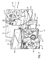
FIG. 7 is still another partial perspective view of the support arrangement ofFIG. 2 , showing a cross-section similar toFIG. 6 . - Like reference numerals in the drawings indicate like components, parts, or operations. "Forward," and "rearward" references (and, generally, references to the "longitudinal" direction) are used herein as a matter of convenience and are generally determined based upon the normal direction of travel for a relevant vehicle. Similarly, references to the "lateral" direction generally refer to directions transverse to the longitudinal direction, with the "left" and "right" directions being determined based from a perspective facing the forward direction for a vehicle. "Upward" and "downward." or "vertical" directions are relative to the ground.
- As noted above, it may be useful to arrange internal components and devices of a vehicle (e.g., an agricultural combine) such that available space is efficiently utilized. In certain embodiments, a useful support arrangement for a vehicle may include an axle assembly with an integrated transmission. In certain embodiments, such an integrated axle and transmission arrangement may allow the transmission to be disposed in relatively close proximity to the axle assembly without excessive use of space. This may, for example, allow relatively efficient and direct routing of power from the transmission to the relevant wheels (e.g., via one or more drive shafts extending from the transmission toward the wheels).
- An axle assembly for an integrated axle and transmission arrangement may include an axle support structure configured as an arrangement of support plates within the body of the vehicle. The various support plates may be welded together, or otherwise attached, such that the plates define (at least in part) an internal volume. Stub shafts (e.g., weldments of various plates) may be attached at either lateral side of the support structure, and wheels (or tracks, and so on) of the vehicle may be attached to the stub shafts. Both of the stub shafts and at least part of the internal volume defined by the axle support structure may be generally oriented along a common axis of rotation of the wheels (i.e., along the axle axis).
- In order to controllably drive the wheels mounted to the stub shafts, a transmission assembly may be mounted within the mounting volume. For example, a transmission assembly including a multi-stage (or other) transmission may be mounted to a front plate of the axle support structure, such that the multi-stage (or other) transmission extends rearward into the internal volume of the axle support structure. In such a configuration, an output shaft may extend from either lateral side of the transmission assembly in order to provide rotational power to the wheels.
- In certain embodiments, the wheels may be attached to the stub axles via a wheel plate, which may extend from the axle axis to below side plates of the axle support structure. A tension rod (or other tie member) may be attached to the two side plates, and extend between the two side plates, such that the tension rod (or other tie member) may provide structural support to the axle assembly as the wheels support the weight of the vehicle.
- In certain embodiments, an additional (or alternative) useful support arrangement for a vehicle (e.g., an agricultural combine) may include an integrated fan and axle arrangement. For example, a cleaning shoe (or other cleaning device) of a vehicle may be configured to separate various portions of crop material using (at least in part) an air flow generated by a fan. The fan may include an impeller and a scroll for generating the air flow for the cleaning shoe (or other device). A front axle assembly of a combine (or other vehicle) may include various support plates (or other members) that are welded (or otherwise attached) into a suitable support structure for the axle (e.g., a central axle support structure and laterally extending stub axles). In order to increase the available space for the cleaning shoe (or other device), a portion of the scroll of the fan may be configured as a portion of the axle assembly (or, conversely, a portion of the axle assembly may be configured as a portion of the scroll). In this way, the scroll may serve its function with regard to the air flow from the fan, while also providing structural rigidity to the axle assembly (or, conversely, a support plate of the axle assembly may provide structural rigidity to the axle assembly while also forming a portion of the fan scroll).
- Referring now to
FIG. 1 , one or more of the disclosed support arrangements may be utilized with respect to an exampleagricultural vehicle 10 with achassis 10a. As depicted, thevehicle 10 is in the form of an agricultural combine. It will be understood, however, that the support arrangements disclosed herein may also be utilized with otheragricultural vehicles 10, including other combines, which may be configured differently than thevehicle 10. Thus, aspects of this disclosure are not limited to the configuration of theexample vehicle 10. - The
vehicle 10 may include front and rear ground-engaging elements for supporting thevehicle 10 with respect to the ground. As depicted inFIG. 1 , for example, thevehicle 10 is supported by a pair of front wheels 12 (left and right), and a pair of rear wheels 14 (left and right). (Right side wheels 12 and 14 are hidden from view inFIG. 1 .) Thefront wheels 12 may be attached to afront axle assembly 16, and the rear wheels 14 may be attached to a rear axle assembly (not shown). Power from anengine 36 may be transmitted to thewheels 12 via various intermediary systems (e.g., various transmissions, motors, generators, pumps, and so on). In certain embodiments, tracks or other ground-engaging elements may be used instead ofwheels 12 or 14. - A
header 18 may gather crop material from a field, while afeederhouse 20 to which theheader 18 is attached may direct the gathered crop towards acrop processing unit 22 within thevehicle 10. Thecrop processing unit 22 may include, for example, aseparator 24, a cleaning device configured as acleaning shoe 26, a cleaning fan 28, and various other devices, for separating grain (or other saleable or useful products) from chaff and other trash. It will be understood that other embodiments of thevehicle 10 may include cleaning devices configured differently from a cleaning shoe. - Referring also to
FIGS. 2-5 , an improved arrangement of anaxle assembly 16a, acleaning shoe 26a, and afan 28a are depicted. It will be understood that various aspects of this improved arrangement, as discussed in greater detail below, may be implemented individually or collectively, in different embodiments. - As depicted, the
axle assembly 16a includes a centrally disposedaxle support structure 40, and a pair ofstub axles front wheels 12 to theagricultural vehicle 10. Thestub axles axle support structure 40 may be configured to provide a suitably rigid structure for support of the weight of thevehicle 10 at thewheels 12. As depicted, theaxle support structure 40 is centrally disposed, and relatively symmetric with regard to a centerline of thevehicle 10. In other embodiments, a similar support structure (not shown) may be offset from the centerline of thevehicle 10, may be non-symmetrical in various ways, or may otherwise differ from the depictedaxle support structure 40. - In certain embodiments, as also discussed in greater detail below, the
axle support structure 40 may provide a mounting frame for attachment of atransmission assembly 30, which may be utilized to drive thewheels 12. A transmission assembly for thevehicle 10 may be configured in a variety of ways. Thetransmission assembly 30, for example, may include a motor (e.g., a hydraulic motor) powered by theengine 36 and a gear box (e.g., a differential gear box or multi-stage transmission) configured to transmit power received at a transmission input to thewheels 12. The motor may accordingly, for example, provide power to drive thewheels 12 via the transmission gear box. In other configurations, thetransmission assembly 30 may be configured in various different ways, and may, for example, include various other devices, such as other motors, other gear boxes, various clutch devices, and so on. - The
axle support structure 40 may be formed from a number of longitudinally extending side members, which may be connected to each other by a number of laterally extending cross members. As depicted, for example, theaxle support structure 40 includesside plates internal volume 46. In certain embodiments, theside plates vehicle 10. In such embodiments, thestub axles side plates vehicle 10. - To provide appropriate structural strength to the
axle support structure 40, a laterally extendingupper support structure 48 may be welded (or otherwise attached) to each of theside plates support structure 48 may be viewed as further defining theinternal volume 46. As depicted, thesupport structure 48 is formed as a weldment of various plates (including angledupper plate 48a), which is attached to theside plates side plates side plates axle support structure 40. - The
axle support structure 40 may further include front and rear members (or other support members or structures). For example, in the embodiment depicted, afront plate 50 may be welded (or otherwise attached) to each of theside plates axle support structure 40. In certain embodiments, as discussed in greater detail below, the front plate 50 (or another plate) may be configured as a mounting plate for thetransmission assembly 30, as well as a structural member of theaxle support structure 40. In such embodiments, the front plate 50 (or another plate) may also be viewed as a "transmission mounting plate." It will be understood, however, that other configurations are possible. For example, an alternative (or additional) member or support structure for connecting the front portions of theside plates plate 50 may alternatively (or additionally) be utilized as a transmission mounting plate. - The various support members and structures of the
axle support structure 40 may generally form a partial shell or shield around theinternal volume 46. Such a shell may for example, include front, top and rear walls (e.g., as formed by thefront plate 50,upper support structure 48, and so on), with a generally open bottom. In this way, for example, even if theaxle support structure 40 is formed as a weldment, it may be relatively straightforward to access theinternal volume 46 from the bottom of theaxle support structure 40. This may result, for example, in more streamlined maintenance of various components of thevehicle 10, including thetransmission assembly 30 when thetransmission assembly 30 is mounted within theinternal volume 46. - The
stub axles FIG. 5 , the depicted stub axle 34 (like the stub axle 32) is formed from a tube-shapedweldment 34a, which may be welded (or otherwise attached) to theside plate 44. As can be seen inFIGS. 2 and3 , in the depicted embodiment, thedrive plates 52 may be attached (e.g., welded) to theweldment 34a. Weldedflange plates 34b, anupper flange 34c, one ormore ribs 34d, and various other structures (e.g., one ormore plates 34e) may also be included, in order to reinforce theweldment 34a and thestub axle 34 in general. It will be understood, however, that other configurations are possible. For example, an alternative (or additional) stub axle (or portion thereof) may be formed as a hollow tube, box, or other weldment, each configured to provide appropriate structural rigidity and strength to support the weight of the vehicle at thewheels 12. - In the embodiment depicted, the
stub axles drive axis 12a (i.e., axis of rotation) of the wheels 12 (see, e.g.,FIG. 2 ). In this regard, thestub axles axle assembly 16a may be viewed as coaxially disposed withdrive axis 12a of thewheels 12. - Each of the
stub axles stub axles FIG. 3 , for example, adrive plate 52 is attached at the laterally outer end of eachstub axle drive plate 52 may be configured to support a final drive 54 (e.g., via various bolts, and so on), which may in turn support therelevant wheel 12. Eachfinal drive 54 may include, for example, a gear box having a fixed portion that attaches to therelevant drive plate 52 and a rotatable portion that attaches to therelevant front wheel 12. In the embodiment depicted,ribs FIGS. 2 and5 ) extend from theside plates drive plates 52. - A structural tie member (e.g., a tension rod 38) may attach to, and extend between, each of the
drive plates 52 in order to provide further structural rigidity to theaxle assembly 16a. In the embodiment depicted, for example, thedrive plates 52 are configured to extend downward from thestub axles drive plates 52 are generally below the lower edges of theside plates axle support structure 40. Thetension rod 38 is attached (e.g., secured by threadedconnections 38a) at a location near the lower ends of thedrive plates 52, such that thetension rod 38 is disposed generally below theaxle support structure 40. It will be understood, however, that other configurations are possible. For example, the tension rod 38 (or another tie member) may be configured to extend through theside plates axle assembly 16a. - As noted above, the
transmission assembly 30 for thefront wheels 12 may be mounted such that thetransmission assembly 30 is disposed (at least in part) withininternal volume 46 of theaxle support structure 40. In this way, theaxle support structure 40 may both support thetransmission assembly 30 with respect to theagricultural vehicle 10, and at least partially enclose thetransmission assembly 30. This may serve to protect the transmission assembly 30 (at least in part) from impacts or other adverse events, while also efficiently utilizing the limited internal space of thevehicle 10. - In the embodiment depicted, the
transmission assembly 30 is configured to attach to thefront plate 50 of the axle support structure 40 (i.e., such that thefront plate 50 may be viewed as a mounting plate for the transmission assembly 30). Accordingly, thefront plate 50 is configured to support thetransmission assembly 30, and theinternal volume 46 is configured to receive thetransmission assembly 30, such that thetransmission assembly 30 is disposed (at least in part) within theinternal volume 46. In this regard, theinternal volume 46 may be viewed as a "mounting volume" of the axle support structure 40 (and of theaxle assembly 16, generally). Various attachment devices or arrangements may be utilized to attach thetransmission assembly 30 to thefront plate 50, including various bolts, brackets, hooks, pins, and so on. Where bolts or other removable attachment devices are utilized, thetransmission assembly 30 may be relatively easily removed from theaxle support structure 40 for maintenance. - As depicted, the
front plate 50 and theinternal volume 46 are configured such that theentire transmission assembly 30 is disposed within thevolume 46 when thetransmission assembly 30 is attached to thefront plate 50 for operation. In other embodiments, a relevant mounting plate and mounting volume may be otherwise configured, such that only a portion of thetransmission assembly 30 is disposed within the mounting volume. In certain embodiments, thetransmission assembly 30 may be configured to attach to various plates (or other members) of theaxle assembly 16a as an alternative to (or in addition to) thefront plate 50. - In certain embodiments, additional components or devices may also be included (at least in part) within the relevant mounting volume for the vehicle transmission (e.g., within the
internal volume 46 of the axle support structure 40). As depicted, for example, a hydraulic (or other) motor 56 for providing rotational power to thetransmission assembly 30 is also disposed within theinternal volume 46. Themotor 56 may be supported with respect to thevehicle 10 by the front plate 50 (e.g., via attachment of themotor 56 to the transmission assembly 30) or by other features of theaxle assembly 16a. - In order to convey rotational power from the
transmission assembly 30 to thewheels 12, drive shafts may be configured to extend laterally from thetransmission assembly 30 to thefinal drives 54. As depicted, for example, ashaft opening 76 is provided in each of theside plates drive shaft 58 may extend through eachopening 76, respectively, such that rotational power may be transmitted from thetransmission assembly 30, via thefinal drives 54, to thewheels 12. - In certain embodiments of the
vehicle 10, a transmission for the front wheels 14 may not be disposed within theaxle assembly 16a. For example, in certain embodiments, a transmission (e.g., a transmission configured similarly to the transmission 30) may be disposed forward of theaxle assembly 16a rather than within theaxle assembly 16a. Accordingly, although such a transmission (not shown) may be supported by a front portion of theaxle assembly 16a, the transmission may not be enclosed by theaxle assembly 16a. It will be understood, in this light, that certain discussion below relating to the configuration of the axle support structure 40 (or portions thereof) may apply generally to axle assemblies (e.g., the axle assembly 16), regardless of the actual location or configuration of thetransmission assembly 30. - As also noted above, it may be useful to configure a fan of a cleaning shoe (or similar other fan) to share at least one structural member with an axle assembly. Referring also to
FIGS. 6 and7 , for example, acleaning shoe 26a may includeside sheets cleaning shoe 26a. Thefan 28a may be disposed, at least in part, between theside sheets fan 28a includes a laterally extendingimpeller 74, eachside sheet circular opening 76 passing laterally through theside sheets circular openings 76 of theside sheets - To protect the
impeller 74 and other components, and to appropriately route air flow, thefan 28a includes afan housing 78. As depicted, thefan housing 78 is formed in part by theside sheets cleaning shoe 26a. It will be understood however, that other configurations are possible. - As depicted, the
fan housing 78 also includes ascroll 80 to route air from theimpeller 74 of the fan to the rearward portion of thecleaning shoe 26a. Generally, thescroll 80 may be formed in a logarithmic or other spiral, although other configurations are also possible. For convenience of reference herein, the scroll 80 (and the impeller 74) may be divided into four quadrants, an upperrearward quadrant 100, an upperforward quadrant 102, a lowerforward quadrant 104, and a lowerrearward quadrant 106. As depicted, thescroll 80 generally begins in the upperrearward quadrant 100, then traces a profile that extends radially outward and clockwise (e.g., from the perspective ofFIG. 5 ) through the upperforward quadrant 102, the lowerforward quadrant 104, and part of the lowerrearward quadrant 106. It will be understood, however, that other configurations may be possible, depending on the characteristics of thefan 28a and the desired air flow. - As depicted, the
scroll 80 is formed of a plurality ofscroll plates 82, which may extend laterally between theside sheets side sheets brackets 84 andfasteners 86. Thevarious scroll plates 82 may also attach to one another in various ways, in order to provide a continuous (or nearly continuous) shell around animpeller 74 of thefan 28a. In this way, the scroll 80 (by way of the scroll plates 82) may generally define an air-flow gap 88 (see, e.g.,FIGS. 6 and7 ) between thescroll 80 and theimpeller 74 of the cleaningfan 28a. - As shown in particular in
FIGS. 6 and7 , theimpeller 74 for thecleaning shoe 26a may includevarious blades 108 extending outward from an axis ofrotation 74a extending along the centerline of the impeller 74 (see, e.g.FIG. 7 ). As theimpeller 74 rotates about the axis ofrotation 74a, the successive positions of the tips of the blades 108 (or other radially extended portions of the impeller 74) trace a generally circular outer boundary for theimpeller 74. The air-flow gap 88 may be further defined, at least in part, by the path traced by this outer boundary. - In this light, as the
impeller 74 rotates, air from theimpeller 74 may be routed from thefan 28a, along a counter-clockwise path (from the perspective ofFIG. 6 ) through the air-flow gap 88, to rearward portions of thecleaning shoe 26a. In this way, an appropriately configuredscroll 80 may contribute to effective and efficient cleaning of crop material within thecleaning shoe 26a. - The width of the air-
flow gap 88 in a radial direction, with a radial center coaxial with the cleaningfan 28a, may vary along thescroll 80. As depicted, for example, thegap 88 is smallest at the start of the scroll 80 (i.e., in the upper rearward quadrant 100) and widens relatively continuously to its widest point at the end of the scroll 80 (i.e., in the lower rearward quadrant 106). It will be understood, however, that other configurations may be possible. - In the embodiment depicted, each
scroll plate 82 defines a generally flat contour (or series of flat contours) along thescroll 80, with thescroll plates 82 thereby collectively approximating a curved, spiral shape even though noindividual scroll plate 82 may actually be curved. It will be understood, however, that other embodiments of thefan 28a and thefan housing 78 may alternatively (or additionally) include various curved plates to define thescroll 80. Likewise, thescroll 80 may be formed from a single sheet or plate, rather than themultiple scroll plates 82, whether thescroll 80 is curved, angled to approximate a curve, or otherwise contoured. - In order to utilize internal space of the
vehicle 10 in an efficient manner, thecleaning shoe 26a and thefront axle assembly 16a may share, and may connect to each other through, one or more shared structural members (or other support structures). In certain embodiments, the scroll of thefan 28a for thecleaning shoe 26a may share one or more structural members with theaxle assembly 16a. In the embodiment depicted in the various figures, for example, one of thescroll plates 82 of thefan scroll 80 is also configured as a rearward support plate 110 for thesupport structure 40 of theaxle assembly 16a. In this way, the plate 110 may provide structural support to thesupport structure 40 of thefront axle assembly 16a, as well as to thefan housing 78, while simultaneously serving, at least in part, to define the contour of thescroll 80. - The shared members or structures of the
scroll 80 andaxle assembly 16a may be configured in a variety of ways. In certain embodiments, the shared support member may be include one or more portions that do not serve to define the contours of thescroll 80. As depicted, for example, the support plate 110 includes ascroll section 112, which may serve to define a portion of the scroll 80 (and, thereby, the air-flow gap 88). Also as depicted, the support plate 110 further includes asupport section 114, which extends generally downward from the scroll section 112 (and away from the air-flow gap 88) to provide additional structural support to theaxle assembly 16a. - As depicted, the
scroll section 112 of the support plate 110 includes two flat portions connected at an angle, in order to approximate the desired curve of thescroll 80. In other embodiments, thescroll section 112 may instead be curved, or otherwise contoured. Similarly, thescroll section 112 and thesupport section 114 of the plate 110 are depicted as formed from a single metal sheet. It will be understood, however, that other configurations are possible. For example, the structure provided by plate 110 may, in certain embodiments, be instead provided by two or more separate plates (or other members). Such separate plates may be fastened together (e.g., by welding or bolts) for attachment to theaxle assembly 16a andfan 28a, or may be attached to theaxle assembly 16a andfan 28a separately. - In certain embodiments, the various members of the
axle support structure 40 may define one or more passages from the exterior of the axle support structure 40 (and theaxle assembly 16a, generally) into theinternal volume 46. In the embodiment depicted, for example, a passage 116 is defined by theupper support structure 48 and the scroll 80 (including the support plate 110). As can be seen in particular inFIG. 6 , the passage 116 extends upward and rearward from theinternal volume 46 to the exterior of theaxle support structure 40. Such a passage may be useful, for example, to reduce the build-up of debris (e.g., dirt and stones) within thevolume 46. Further, such a passage may provide a useful routing path for hydraulic, electronic, or other conduits or cables (e.g., a hydraulic line to power one or more hydraulic motors included in the transmission assembly 30). - In certain embodiments, various spatial relationships between components of the
fan 28a and theaxle assembly 16a may be implemented. Still referring in particular toFIG. 6 , for example, theside sheets side plates impeller 74 of thefan 28a is disposed generally above and laterally between (as viewed from above) theside plates - Other configurations may also be possible. In certain embodiments, for example, the
impeller 74 may be physically between theside plates 42 and 44 (i.e., such a portion of theimpeller 74 longitudinally overlaps with theside plates 42 and 44). Similarly, the shared support plate 110 may be configured without the support section 114 (e.g., configured to include only the scroll portion 90) or may include a different support section (e.g., a support section extending forward towards thetransmission assembly 30 or rearward toward thecleaning shoe 26a).
Claims (11)
- An integrated fan and axle arrangement for an agricultural vehicle (10) having an impeller (74) with an axis of rotation (74a) that extends laterally across a chassis (10a) of the agricultural vehicle, the integrated fan and axle arrangement comprising:a front axle assembly (16a) configured to support one or more front wheels (12) of the agricultural vehicle; anda fan housing (78), wherein the impeller rotates within the fan housing to provide air flow within the agricultural vehicle;wherein a laterally extending portion (82, 110) of the fan housing forms part of the front axle assembly, such that the laterally extending portion of the fan housing provides structural rigidity to the front axle assembly for the support of the one or more front wheels.
- The integrated fan and axle arrangement of claim 1, wherein a plurality of blades (108) are attached to the impeller, the plurality of blades defining an outer boundary of the impeller as the impeller rotates within the fan housing;
wherein the fan housing includes a fan scroll (80) with one or more scroll plates (82), wherein the one or more scroll plates define an air-flow gap (88) between the fan scroll and the outer boundary of the impeller, and the impeller provides the air flow via the air-flow gap; and
wherein the laterally extending portion of the fan housing that forms part of the front axle assembly includes at least one scroll plate of the one or more scroll plates. - The integrated fan and axle arrangement of claim 2, wherein the front axle assembly includes first and second side plates (42, 44) on opposite lateral sides of the front axle assembly; and
wherein the at least one scroll plate extends laterally across the agricultural vehicle from a first end at the first side plate of the front axle assembly to a second end at the second side plate of the front axle assembly. - The integrated fan and axle arrangement of claim 3, wherein the first and second side plates extend past the at least one scroll plate toward the impeller.
- The integrated fan and axle arrangement of claim 2, wherein the at least one scroll plate includes a scroll section (112) and a support section (114);
wherein the scroll section defines, at least in part, the air-flow gap between the fan scroll of the fan housing and the outer boundary of the impeller; and
wherein the support section extends away from the scroll section and the impeller such that the support section is excluded, at least in part, from the fan scroll of the fan housing. - The integrated fan and axle arrangement of claim 5, wherein the front axle assembly includes first and second side plates on opposite lateral sides of the front axle assembly; and
wherein the support section of the at least one scroll plate extends, at least in part, away from the scroll section towards a lower edge of each of the first and second side plates. - The integrated fan and axle arrangement of claim 2, wherein the at least one scroll plate defines the air-flow gap for at least part of a forward, lower quadrant (104) of the impeller.
- The integrated fan and axle arrangement of claim 1, wherein the impeller is disposed, at least in part, above the front axle assembly.
- The integrated fan and axle arrangement of claim 8, wherein the front axle assembly includes first and second side plates on opposite lateral sides of the front axle assembly; and
wherein the impeller is disposed, at least in part, above and laterally between the first and second side plates. - The integrated fan and axle arrangement of claim 1, wherein the front axle assembly includes an upper support structure (48) extending laterally between first and second side plates of the front axle assembly; and
wherein the upper support structure and the laterally extending portion of the fan housing are disposed to define a passage (116) between the upper support structure and the laterally extending portion of the fan housing, the passage extending from outside of the front axle assembly to an internal volume (46) of the front axle assembly. - An agricultural vehicle with an arrangement according to one of the preceding claims.
Applications Claiming Priority (1)
| Application Number | Priority Date | Filing Date | Title |
|---|---|---|---|
| US14/473,804 US9750192B2 (en) | 2014-08-29 | 2014-08-29 | Integrated fan and axle arrangement for an agricultural vehicle |
Publications (2)
| Publication Number | Publication Date |
|---|---|
| EP2992752A1 true EP2992752A1 (en) | 2016-03-09 |
| EP2992752B1 EP2992752B1 (en) | 2018-06-06 |
Family
ID=53835267
Family Applications (1)
| Application Number | Title | Priority Date | Filing Date |
|---|---|---|---|
| EP15178260.4A Active EP2992752B1 (en) | 2014-08-29 | 2015-07-24 | Integrated fan and axle arrangement for an agricultural vehicle |
Country Status (3)
| Country | Link |
|---|---|
| US (1) | US9750192B2 (en) |
| EP (1) | EP2992752B1 (en) |
| BR (1) | BR102015020753B1 (en) |
Cited By (2)
| Publication number | Priority date | Publication date | Assignee | Title |
|---|---|---|---|---|
| BE1027577B1 (en) * | 2019-10-01 | 2021-08-03 | Deere & Co | Forage harvester with a supporting frame |
| BE1031318B1 (en) * | 2023-02-24 | 2024-10-22 | Deere & Co | forage harvester with a supporting frame |
Families Citing this family (4)
| Publication number | Priority date | Publication date | Assignee | Title |
|---|---|---|---|---|
| US10653069B2 (en) * | 2014-12-23 | 2020-05-19 | Cnh Industrial America Llc | Residue handling system for an agricultural harvester |
| US10375885B2 (en) * | 2015-09-17 | 2019-08-13 | Deere & Company | System for chopping and spreading residue |
| US10791676B2 (en) * | 2018-03-28 | 2020-10-06 | Cnh Industrial America Llc | Modular combine traction axle |
| US11369058B2 (en) | 2019-03-19 | 2022-06-28 | Deere & Company | Forward-looking perception interface and control |
Citations (5)
| Publication number | Priority date | Publication date | Assignee | Title |
|---|---|---|---|---|
| US3023901A (en) * | 1959-04-13 | 1962-03-06 | Case Co J I | Fan assembly for harvesting machinery |
| US3469773A (en) * | 1968-07-12 | 1969-09-30 | Int Harvester Co | Fan for combine |
| US4265077A (en) * | 1979-08-03 | 1981-05-05 | Deere & Company | Blower system for an axial flow rotary combine cleaning shoe |
| US20040023704A1 (en) * | 2002-07-31 | 2004-02-05 | Grywacheski Sheldon Joseph | Front chaffer and cleaning fan |
| EP1932421A1 (en) * | 2006-12-13 | 2008-06-18 | CNH Belgium N.V. | Integrated axle and cleaning fan wrapper for an agricultural harvesting machine |
Family Cites Families (2)
| Publication number | Priority date | Publication date | Assignee | Title |
|---|---|---|---|---|
| US1831216A (en) * | 1929-05-28 | 1931-11-10 | Caterpillar Tractor Co | Thrashing |
| US5464372A (en) * | 1994-04-26 | 1995-11-07 | Deere & Company | Cleaning fan having snap in blades |
-
2014
- 2014-08-29 US US14/473,804 patent/US9750192B2/en active Active
-
2015
- 2015-07-24 EP EP15178260.4A patent/EP2992752B1/en active Active
- 2015-08-27 BR BR102015020753-0A patent/BR102015020753B1/en active IP Right Grant
Patent Citations (5)
| Publication number | Priority date | Publication date | Assignee | Title |
|---|---|---|---|---|
| US3023901A (en) * | 1959-04-13 | 1962-03-06 | Case Co J I | Fan assembly for harvesting machinery |
| US3469773A (en) * | 1968-07-12 | 1969-09-30 | Int Harvester Co | Fan for combine |
| US4265077A (en) * | 1979-08-03 | 1981-05-05 | Deere & Company | Blower system for an axial flow rotary combine cleaning shoe |
| US20040023704A1 (en) * | 2002-07-31 | 2004-02-05 | Grywacheski Sheldon Joseph | Front chaffer and cleaning fan |
| EP1932421A1 (en) * | 2006-12-13 | 2008-06-18 | CNH Belgium N.V. | Integrated axle and cleaning fan wrapper for an agricultural harvesting machine |
Cited By (2)
| Publication number | Priority date | Publication date | Assignee | Title |
|---|---|---|---|---|
| BE1027577B1 (en) * | 2019-10-01 | 2021-08-03 | Deere & Co | Forage harvester with a supporting frame |
| BE1031318B1 (en) * | 2023-02-24 | 2024-10-22 | Deere & Co | forage harvester with a supporting frame |
Also Published As
| Publication number | Publication date |
|---|---|
| US9750192B2 (en) | 2017-09-05 |
| BR102015020753A2 (en) | 2016-07-05 |
| US20160057928A1 (en) | 2016-03-03 |
| BR102015020753B1 (en) | 2020-11-24 |
| EP2992752B1 (en) | 2018-06-06 |
Similar Documents
| Publication | Publication Date | Title |
|---|---|---|
| EP2992752B1 (en) | Integrated fan and axle arrangement for an agricultural vehicle | |
| EP2990217B1 (en) | Axle and transmission arrangement for an agricultural vehicle | |
| EP2663175B1 (en) | Combine harvester grain cleaning apparatus | |
| BR102015020759A2 (en) | wheel axle arrangement and farm vehicle | |
| WO2023049326A1 (en) | Common drive member for weed seed mill of combine harvester | |
| US10827683B2 (en) | Sieve assembly for a crop processing system of an agricultural harvester | |
| EP3560320B1 (en) | Vented side member for an agricultural vehicle | |
| JP6473052B2 (en) | Barrel | |
| EP3120685B1 (en) | Sieve arrangements for a cleaning system in an agricultural harvester | |
| US10257984B2 (en) | Agricultural harvester with paddles rotated about an axis of rotation that is parallel to a longitudinal axis of the harvester | |
| CN108882680B (en) | threshing drum | |
| US7140961B2 (en) | Combine harvester | |
| EP2996457B1 (en) | Cover plate for a clean grain auger in a cleaning system of an agricultural harvester | |
| BR102017006218B1 (en) | agricultural harvester | |
| CN105050381A (en) | Combine | |
| JP2021040567A (en) | Sugar cane harvester | |
| CN207151249U (en) | Grain combine and its installed threshing separator | |
| JP7321037B2 (en) | sugar cane harvester | |
| EP3545751B1 (en) | Modular combine traction axle | |
| KR20260045643A (en) | Work vehicle | |
| CN114375677A (en) | combine harvester | |
| JP5634096B2 (en) | Combine harvester | |
| JP2013158261A (en) | Wheel-traveling type combine harvester | |
| JP2013158262A (en) | Combine harvester |
Legal Events
| Date | Code | Title | Description |
|---|---|---|---|
| PUAI | Public reference made under article 153(3) epc to a published international application that has entered the european phase |
Free format text: ORIGINAL CODE: 0009012 |
|
| AK | Designated contracting states |
Kind code of ref document: A1 Designated state(s): AL AT BE BG CH CY CZ DE DK EE ES FI FR GB GR HR HU IE IS IT LI LT LU LV MC MK MT NL NO PL PT RO RS SE SI SK SM TR |
|
| AX | Request for extension of the european patent |
Extension state: BA ME |
|
| 17P | Request for examination filed |
Effective date: 20160909 |
|
| RBV | Designated contracting states (corrected) |
Designated state(s): AL AT BE BG CH CY CZ DE DK EE ES FI FR GB GR HR HU IE IS IT LI LT LU LV MC MK MT NL NO PL PT RO RS SE SI SK SM TR |
|
| GRAP | Despatch of communication of intention to grant a patent |
Free format text: ORIGINAL CODE: EPIDOSNIGR1 |
|
| RIC1 | Information provided on ipc code assigned before grant |
Ipc: B60B 35/16 20060101ALI20171206BHEP Ipc: A01F 12/44 20060101AFI20171206BHEP Ipc: A01D 67/00 20060101ALI20171206BHEP Ipc: A01D 41/12 20060101ALI20171206BHEP |
|
| INTG | Intention to grant announced |
Effective date: 20180102 |
|
| GRAS | Grant fee paid |
Free format text: ORIGINAL CODE: EPIDOSNIGR3 |
|
| GRAA | (expected) grant |
Free format text: ORIGINAL CODE: 0009210 |
|
| AK | Designated contracting states |
Kind code of ref document: B1 Designated state(s): AL AT BE BG CH CY CZ DE DK EE ES FI FR GB GR HR HU IE IS IT LI LT LU LV MC MK MT NL NO PL PT RO RS SE SI SK SM TR |
|
| REG | Reference to a national code |
Ref country code: GB Ref legal event code: FG4D |
|
| REG | Reference to a national code |
Ref country code: CH Ref legal event code: EP Ref country code: AT Ref legal event code: REF Ref document number: 1005024 Country of ref document: AT Kind code of ref document: T Effective date: 20180615 |
|
| REG | Reference to a national code |
Ref country code: IE Ref legal event code: FG4D |
|
| REG | Reference to a national code |
Ref country code: DE Ref legal event code: R096 Ref document number: 602015011658 Country of ref document: DE |
|
| REG | Reference to a national code |
Ref country code: NL Ref legal event code: MP Effective date: 20180606 |
|
| REG | Reference to a national code |
Ref country code: LT Ref legal event code: MG4D |
|
| PG25 | Lapsed in a contracting state [announced via postgrant information from national office to epo] |
Ref country code: SE Free format text: LAPSE BECAUSE OF FAILURE TO SUBMIT A TRANSLATION OF THE DESCRIPTION OR TO PAY THE FEE WITHIN THE PRESCRIBED TIME-LIMIT Effective date: 20180606 Ref country code: NO Free format text: LAPSE BECAUSE OF FAILURE TO SUBMIT A TRANSLATION OF THE DESCRIPTION OR TO PAY THE FEE WITHIN THE PRESCRIBED TIME-LIMIT Effective date: 20180906 Ref country code: FI Free format text: LAPSE BECAUSE OF FAILURE TO SUBMIT A TRANSLATION OF THE DESCRIPTION OR TO PAY THE FEE WITHIN THE PRESCRIBED TIME-LIMIT Effective date: 20180606 Ref country code: LT Free format text: LAPSE BECAUSE OF FAILURE TO SUBMIT A TRANSLATION OF THE DESCRIPTION OR TO PAY THE FEE WITHIN THE PRESCRIBED TIME-LIMIT Effective date: 20180606 Ref country code: CY Free format text: LAPSE BECAUSE OF FAILURE TO SUBMIT A TRANSLATION OF THE DESCRIPTION OR TO PAY THE FEE WITHIN THE PRESCRIBED TIME-LIMIT Effective date: 20180606 Ref country code: BG Free format text: LAPSE BECAUSE OF FAILURE TO SUBMIT A TRANSLATION OF THE DESCRIPTION OR TO PAY THE FEE WITHIN THE PRESCRIBED TIME-LIMIT Effective date: 20180906 Ref country code: ES Free format text: LAPSE BECAUSE OF FAILURE TO SUBMIT A TRANSLATION OF THE DESCRIPTION OR TO PAY THE FEE WITHIN THE PRESCRIBED TIME-LIMIT Effective date: 20180606 |
|
| PG25 | Lapsed in a contracting state [announced via postgrant information from national office to epo] |
Ref country code: GR Free format text: LAPSE BECAUSE OF FAILURE TO SUBMIT A TRANSLATION OF THE DESCRIPTION OR TO PAY THE FEE WITHIN THE PRESCRIBED TIME-LIMIT Effective date: 20180907 Ref country code: HR Free format text: LAPSE BECAUSE OF FAILURE TO SUBMIT A TRANSLATION OF THE DESCRIPTION OR TO PAY THE FEE WITHIN THE PRESCRIBED TIME-LIMIT Effective date: 20180606 Ref country code: RS Free format text: LAPSE BECAUSE OF FAILURE TO SUBMIT A TRANSLATION OF THE DESCRIPTION OR TO PAY THE FEE WITHIN THE PRESCRIBED TIME-LIMIT Effective date: 20180606 Ref country code: LV Free format text: LAPSE BECAUSE OF FAILURE TO SUBMIT A TRANSLATION OF THE DESCRIPTION OR TO PAY THE FEE WITHIN THE PRESCRIBED TIME-LIMIT Effective date: 20180606 |
|
| REG | Reference to a national code |
Ref country code: AT Ref legal event code: MK05 Ref document number: 1005024 Country of ref document: AT Kind code of ref document: T Effective date: 20180606 |
|
| PG25 | Lapsed in a contracting state [announced via postgrant information from national office to epo] |
Ref country code: NL Free format text: LAPSE BECAUSE OF FAILURE TO SUBMIT A TRANSLATION OF THE DESCRIPTION OR TO PAY THE FEE WITHIN THE PRESCRIBED TIME-LIMIT Effective date: 20180606 |
|
| PG25 | Lapsed in a contracting state [announced via postgrant information from national office to epo] |
Ref country code: RO Free format text: LAPSE BECAUSE OF FAILURE TO SUBMIT A TRANSLATION OF THE DESCRIPTION OR TO PAY THE FEE WITHIN THE PRESCRIBED TIME-LIMIT Effective date: 20180606 Ref country code: SK Free format text: LAPSE BECAUSE OF FAILURE TO SUBMIT A TRANSLATION OF THE DESCRIPTION OR TO PAY THE FEE WITHIN THE PRESCRIBED TIME-LIMIT Effective date: 20180606 Ref country code: CZ Free format text: LAPSE BECAUSE OF FAILURE TO SUBMIT A TRANSLATION OF THE DESCRIPTION OR TO PAY THE FEE WITHIN THE PRESCRIBED TIME-LIMIT Effective date: 20180606 Ref country code: IS Free format text: LAPSE BECAUSE OF FAILURE TO SUBMIT A TRANSLATION OF THE DESCRIPTION OR TO PAY THE FEE WITHIN THE PRESCRIBED TIME-LIMIT Effective date: 20181006 Ref country code: EE Free format text: LAPSE BECAUSE OF FAILURE TO SUBMIT A TRANSLATION OF THE DESCRIPTION OR TO PAY THE FEE WITHIN THE PRESCRIBED TIME-LIMIT Effective date: 20180606 Ref country code: AT Free format text: LAPSE BECAUSE OF FAILURE TO SUBMIT A TRANSLATION OF THE DESCRIPTION OR TO PAY THE FEE WITHIN THE PRESCRIBED TIME-LIMIT Effective date: 20180606 Ref country code: PL Free format text: LAPSE BECAUSE OF FAILURE TO SUBMIT A TRANSLATION OF THE DESCRIPTION OR TO PAY THE FEE WITHIN THE PRESCRIBED TIME-LIMIT Effective date: 20180606 |
|
| PG25 | Lapsed in a contracting state [announced via postgrant information from national office to epo] |
Ref country code: SM Free format text: LAPSE BECAUSE OF FAILURE TO SUBMIT A TRANSLATION OF THE DESCRIPTION OR TO PAY THE FEE WITHIN THE PRESCRIBED TIME-LIMIT Effective date: 20180606 |
|
| REG | Reference to a national code |
Ref country code: CH Ref legal event code: PL |
|
| REG | Reference to a national code |
Ref country code: DE Ref legal event code: R097 Ref document number: 602015011658 Country of ref document: DE |
|
| PG25 | Lapsed in a contracting state [announced via postgrant information from national office to epo] |
Ref country code: MC Free format text: LAPSE BECAUSE OF FAILURE TO SUBMIT A TRANSLATION OF THE DESCRIPTION OR TO PAY THE FEE WITHIN THE PRESCRIBED TIME-LIMIT Effective date: 20180606 Ref country code: LU Free format text: LAPSE BECAUSE OF NON-PAYMENT OF DUE FEES Effective date: 20180724 |
|
| PLBE | No opposition filed within time limit |
Free format text: ORIGINAL CODE: 0009261 |
|
| STAA | Information on the status of an ep patent application or granted ep patent |
Free format text: STATUS: NO OPPOSITION FILED WITHIN TIME LIMIT |
|
| REG | Reference to a national code |
Ref country code: IE Ref legal event code: MM4A |
|
| PG25 | Lapsed in a contracting state [announced via postgrant information from national office to epo] |
Ref country code: CH Free format text: LAPSE BECAUSE OF NON-PAYMENT OF DUE FEES Effective date: 20180731 Ref country code: LI Free format text: LAPSE BECAUSE OF NON-PAYMENT OF DUE FEES Effective date: 20180731 Ref country code: IE Free format text: LAPSE BECAUSE OF NON-PAYMENT OF DUE FEES Effective date: 20180724 |
|
| 26N | No opposition filed |
Effective date: 20190307 |
|
| PG25 | Lapsed in a contracting state [announced via postgrant information from national office to epo] |
Ref country code: DK Free format text: LAPSE BECAUSE OF FAILURE TO SUBMIT A TRANSLATION OF THE DESCRIPTION OR TO PAY THE FEE WITHIN THE PRESCRIBED TIME-LIMIT Effective date: 20180606 Ref country code: SI Free format text: LAPSE BECAUSE OF FAILURE TO SUBMIT A TRANSLATION OF THE DESCRIPTION OR TO PAY THE FEE WITHIN THE PRESCRIBED TIME-LIMIT Effective date: 20180606 |
|
| PG25 | Lapsed in a contracting state [announced via postgrant information from national office to epo] |
Ref country code: FR Free format text: LAPSE BECAUSE OF NON-PAYMENT OF DUE FEES Effective date: 20180806 |
|
| PG25 | Lapsed in a contracting state [announced via postgrant information from national office to epo] |
Ref country code: AL Free format text: LAPSE BECAUSE OF FAILURE TO SUBMIT A TRANSLATION OF THE DESCRIPTION OR TO PAY THE FEE WITHIN THE PRESCRIBED TIME-LIMIT Effective date: 20180606 |
|
| PG25 | Lapsed in a contracting state [announced via postgrant information from national office to epo] |
Ref country code: MT Free format text: LAPSE BECAUSE OF NON-PAYMENT OF DUE FEES Effective date: 20180724 |
|
| GBPC | Gb: european patent ceased through non-payment of renewal fee |
Effective date: 20190724 |
|
| PG25 | Lapsed in a contracting state [announced via postgrant information from national office to epo] |
Ref country code: TR Free format text: LAPSE BECAUSE OF FAILURE TO SUBMIT A TRANSLATION OF THE DESCRIPTION OR TO PAY THE FEE WITHIN THE PRESCRIBED TIME-LIMIT Effective date: 20180606 |
|
| PG25 | Lapsed in a contracting state [announced via postgrant information from national office to epo] |
Ref country code: GB Free format text: LAPSE BECAUSE OF NON-PAYMENT OF DUE FEES Effective date: 20190724 |
|
| PG25 | Lapsed in a contracting state [announced via postgrant information from national office to epo] |
Ref country code: PT Free format text: LAPSE BECAUSE OF FAILURE TO SUBMIT A TRANSLATION OF THE DESCRIPTION OR TO PAY THE FEE WITHIN THE PRESCRIBED TIME-LIMIT Effective date: 20180606 |
|
| PG25 | Lapsed in a contracting state [announced via postgrant information from national office to epo] |
Ref country code: HU Free format text: LAPSE BECAUSE OF FAILURE TO SUBMIT A TRANSLATION OF THE DESCRIPTION OR TO PAY THE FEE WITHIN THE PRESCRIBED TIME-LIMIT; INVALID AB INITIO Effective date: 20150724 Ref country code: MK Free format text: LAPSE BECAUSE OF NON-PAYMENT OF DUE FEES Effective date: 20180606 |
|
| PGFP | Annual fee paid to national office [announced via postgrant information from national office to epo] |
Ref country code: IT Payment date: 20220721 Year of fee payment: 8 |
|
| PG25 | Lapsed in a contracting state [announced via postgrant information from national office to epo] |
Ref country code: IT Free format text: LAPSE BECAUSE OF NON-PAYMENT OF DUE FEES Effective date: 20230724 |
|
| PGFP | Annual fee paid to national office [announced via postgrant information from national office to epo] |
Ref country code: BE Payment date: 20240729 Year of fee payment: 10 |
|
| PGFP | Annual fee paid to national office [announced via postgrant information from national office to epo] |
Ref country code: DE Payment date: 20250620 Year of fee payment: 11 |
|
| REG | Reference to a national code |
Ref country code: BE Ref legal event code: MM Effective date: 20250731 |
|
| PG25 | Lapsed in a contracting state [announced via postgrant information from national office to epo] |
Ref country code: BE Free format text: LAPSE BECAUSE OF NON-PAYMENT OF DUE FEES Effective date: 20250731 |