EP3545751B1 - Modular combine traction axle - Google Patents
Modular combine traction axle Download PDFInfo
- Publication number
- EP3545751B1 EP3545751B1 EP19165349.2A EP19165349A EP3545751B1 EP 3545751 B1 EP3545751 B1 EP 3545751B1 EP 19165349 A EP19165349 A EP 19165349A EP 3545751 B1 EP3545751 B1 EP 3545751B1
- Authority
- EP
- European Patent Office
- Prior art keywords
- tube
- axle assembly
- combine
- axle
- modular
- Prior art date
- Legal status (The legal status is an assumption and is not a legal conclusion. Google has not performed a legal analysis and makes no representation as to the accuracy of the status listed.)
- Active
Links
Images


Classifications
-
- A—HUMAN NECESSITIES
- A01—AGRICULTURE; FORESTRY; ANIMAL HUSBANDRY; HUNTING; TRAPPING; FISHING
- A01D—HARVESTING; MOWING
- A01D67/00—Undercarriages or frames specially adapted for harvesters or mowers; Mechanisms for adjusting the frame; Platforms
-
- A—HUMAN NECESSITIES
- A01—AGRICULTURE; FORESTRY; ANIMAL HUSBANDRY; HUNTING; TRAPPING; FISHING
- A01F—PROCESSING OF HARVESTED PRODUCE; HAY OR STRAW PRESSES; DEVICES FOR STORING AGRICULTURAL OR HORTICULTURAL PRODUCE
- A01F12/00—Parts or details of threshing apparatus
- A01F12/44—Grain cleaners; Grain separators
- A01F12/444—Fanning means
-
- B—PERFORMING OPERATIONS; TRANSPORTING
- B60—VEHICLES IN GENERAL
- B60B—VEHICLE WHEELS; CASTORS; AXLES FOR WHEELS OR CASTORS; INCREASING WHEEL ADHESION
- B60B35/00—Axle units; Parts thereof ; Arrangements for lubrication of axles
- B60B35/004—Mounting arrangements for axles
- B60B35/006—Mounting arrangements for axles with mounting plates or consoles fitted to axles
-
- B—PERFORMING OPERATIONS; TRANSPORTING
- B60—VEHICLES IN GENERAL
- B60B—VEHICLE WHEELS; CASTORS; AXLES FOR WHEELS OR CASTORS; INCREASING WHEEL ADHESION
- B60B35/00—Axle units; Parts thereof ; Arrangements for lubrication of axles
- B60B35/02—Dead axles, i.e. not transmitting torque
- B60B35/04—Dead axles, i.e. not transmitting torque straight
-
- B—PERFORMING OPERATIONS; TRANSPORTING
- B60—VEHICLES IN GENERAL
- B60B—VEHICLE WHEELS; CASTORS; AXLES FOR WHEELS OR CASTORS; INCREASING WHEEL ADHESION
- B60B35/00—Axle units; Parts thereof ; Arrangements for lubrication of axles
- B60B35/12—Torque-transmitting axles
- B60B35/16—Axle housings
- B60B35/163—Axle housings characterised by specific shape of the housing, e.g. adaptations to give space for other vehicle elements like chassis or exhaust system
-
- B—PERFORMING OPERATIONS; TRANSPORTING
- B60—VEHICLES IN GENERAL
- B60K—ARRANGEMENT OR MOUNTING OF PROPULSION UNITS OR OF TRANSMISSIONS IN VEHICLES; ARRANGEMENT OR MOUNTING OF PLURAL DIVERSE PRIME-MOVERS IN VEHICLES; AUXILIARY DRIVES FOR VEHICLES; INSTRUMENTATION OR DASHBOARDS FOR VEHICLES; ARRANGEMENTS IN CONNECTION WITH COOLING, AIR INTAKE, GAS EXHAUST OR FUEL SUPPLY OF PROPULSION UNITS IN VEHICLES
- B60K17/00—Arrangement or mounting of transmissions in vehicles
- B60K17/04—Arrangement or mounting of transmissions in vehicles characterised by arrangement, location or kind of gearing
- B60K17/043—Transmission unit disposed in on near the vehicle wheel, or between the differential gear unit and the wheel
- B60K17/046—Transmission unit disposed in on near the vehicle wheel, or between the differential gear unit and the wheel with planetary gearing having orbital motion
-
- A—HUMAN NECESSITIES
- A01—AGRICULTURE; FORESTRY; ANIMAL HUSBANDRY; HUNTING; TRAPPING; FISHING
- A01F—PROCESSING OF HARVESTED PRODUCE; HAY OR STRAW PRESSES; DEVICES FOR STORING AGRICULTURAL OR HORTICULTURAL PRODUCE
- A01F12/00—Parts or details of threshing apparatus
- A01F12/44—Grain cleaners; Grain separators
- A01F12/446—Sieving means
Definitions
- the present invention relates to a rigid axle for a combine harvester.
- One way to increase harvesting and grain processing and handling capacity is to add an additional cleaning fan, which may also be referred to herein as a pre-blower, at or near the front axle of the combine.
- the pre-blower is used to generate a rearwardly directed flow of air to sieves of a cleaning system for removing material other than grain from the grain itself before it is conveyed to the grain tank or offloaded.
- Adding the pre-blower at or near the front axle of the combine presents a substantial design challenge because a standard rigid front axle cannot accommodate the physical envelope of the pre-blower.
- the front axle must be modified to accommodate the physical envelope of the pre-blower.
- the front axle must be modified because it is not possible to simply increase the overall size envelope of the combine.
- the overall size envelope of the combine is limited by width restrictions for passage over public roads, thoroughfares, bridges and the like, by height restrictions for passage under overhead wires and through doors of storage and service buildings, and trailer transport restrictions.
- GB 2 024 595 A describes an axial flow combine harvester including a cleaning unit with an axial blower.
- US 9 750 192 B2 describes an integrated fan and axle arrangement for an agricultural vehicle.
- the wheels may be wheels having pneumatic tires or wheels for driving an endless track.
- the modular axle assembly may be used with a variety of agricultural vehicles, not limited to a single or dual front wheel combine and a front track combine.
- the modular axle assembly accommodates different variations of feeder pivot locations, feeder lengths and lift geometry.
- a modular axle assembly according to claim 1 is disclosed.
- a combine harvester according to claim 10 is disclosed.
- forward when used in connection with the agricultural harvester and/or components thereof are usually determined with reference to the direction of forward operative travel of the harvester, but again, they should not be construed as limiting.
- longitudinal and “transverse” are determined with reference to the fore-and-aft direction of the agricultural harvester and are equally not to be construed as limiting.
- a combine harvester 100 (hereinafter also referred to as “combine 100") is shown including a rigid axle structure 200 (referred to hereinafter as axle 200) to which drive wheels 124 are connected.
- a pre-blower cleaning fan 116 is mounted to the axle 200 for blowing a flow of air upwardly and rearwardly, as denoted by arrows in FIG. 1 , through sieves of a cleaning system 118 of the combine 100.
- the cleaning system 118 is operable in the well-known manner for separating material other than grain from grain harvested by combine 100.
- a feeder 126 is connected to the front end of the combine 100 for delivering crop material into the threshing system 128 of the combine 100.
- the forward and mid portions of the combine 100 are illustrated in FIG. 1 , and it is contemplated that the axle 200 is preferably configured for use in connection with forwardly located drive wheels of a combine, although the present invention is not intended to be limited by that application.
- Other details of the combine 100 are disclosed in U.S. Patent No. 7,670,219 , which is incorporated by reference herein in its entirety.
- the axle 200 generally comprises an upper tube 202 that is mounted to a lower tube 204 by a series of brackets 206 and 207.
- Each tube 202 and 204 is (optionally) a hollow structure in the interest of reducing weight.
- the tubes 202 and 204 could be solid structures.
- the axle 200 is stationary and rigid during operation.
- the tubes may be rotatable shafts.
- a hollow cylindrical flange 208 is mounted to each end of each of the tubes 202 and 204.
- Each flange 208 includes a hollow small diameter portion 208a for fitting over the end of a tube 202, 204.
- the small diameter portion 208a may be connected to the tube 202, 204 by a weld, for example.
- Each flange 208 also includes a large diameter portion 208b having transverse holes 208c that pass there through. Fasteners (not shown) pass through the holes 208c for fastening the large diameter portion 208b of the flange 208 to another component that is mated to the axle 200.
- the brackets 206 connect the tubes 202, 204 to each other and are spaced apart along the length dimension of the tubes 202, 204.
- the ends of each bracket 206 are fixed to the tubes 202, 204 by a weld, for example.
- Each bracket 206 comprises two V-shaped plates 209 that are spaced apart by a predetermined distance.
- An opening 213 is disposed in each plate 209.
- a support member 211 is positioned between the adjacent plates 209.
- the bracket 207 is box shaped, and also connects the tubes 202, 204 to each other.
- the bracket 207 is positioned between the brackets 206.
- the ends of the bracket 207 are fixed to the tubes 202, 204 by a weld, for example.
- the top surface of the bracket 207 is rounded to conform to the cylindrical body of the tube 202.
- the bottom surface of the bracket 207 is rounded to conform to the cylindrical body of the tube 204.
- a transmission for moving the wheels 124 of the combine 100 may be connected to the bracket 207, as is disclosed in U.S. Patent No. 7,670,219 and shown in FIG. 9B .
- a pre-blower 922 may be at least partially positioned between the tubes 202, 204. Replacing a large solid axle with the two tubes 202 and 204 provides clearance space for accommodating at least a portion of the pre-blower 922.
- Various other components may be connected to the brackets 206 and 207.
- the axle 200 is a modular base unit meaning that a variety of components can be connected, either directly or indirectly, to the axle 200 in order to form different front axle assemblies.
- Various front axle assemblies are described hereinafter, each of which incorporates the modular axle 200.
- the axle 200 is a light-weight rigid axle for a combine that will (i) accommodate the physical envelope of the additional cleaning fan, (ii) work with the variety of different combine styles, and (iii) safely and durably support the weight of the combine machine.
- FIGs. 3A and 3B depicts a rigid front axle assembly 300 for a dual front wheel combine.
- the rigid front axle assembly 300 comprises the axle 200.
- Mounts 310 are fixed to opposing ends of the lower tube 204 of the axle 200.
- each mount 310 comprises two triangular shaped flanges 311 that extend forward of the tube 204, and include openings 305 defined therethrough.
- the flanges 311 are welded (or otherwise fixedly mounted) to the tube 204.
- a plate 313 is mounted to the lower edge of the adjacent flanges 311.
- the mounts 310 provide a suitable jacking or cribbing location for the combine.
- hydraulic cylinders (not shown) extending from the feeder 126 are releasably connected to the openings 305 in the respective mounts 310 for pivoting the feeder 126 with respect to the combine.
- the interconnection between a hydraulic cylinder, a feeder and a combine axle is shown in U.S. Patent No. 8726622 , which is incorporated by reference in its entirety. As will be described in detail later, the structure of each mount can vary.
- a wheel support member 302 is bolted (or otherwise mounted) to both of the tubes 202 and 204 of the axle 200, an axle extension 304 is bolted (or otherwise mounted) to a laterally outwardly face of the wheel support member 302, and a planetary final drive 306 is bolted (or otherwise mounted) to a laterally outwardly face of the axle extension 304.
- Each planetary final drive includes a rotating plate 308. Although not shown, two front wheels are mounted to each plate 308 such that the axle assembly 300 supports a total of four front wheels.
- the final drive 306 is a planetary final drive, however, the final drive 306 could be a bull gear final drive, an electric motor, a hydraulic motor, a pneumatic motor, or another other type of final drive known to those skilled in the art.
- the wheel support member 302 is mounted to the frame of the combine and is a structural member of the combine to which other components are mounted.
- the wheel support member 302 includes flange mounting areas 303a and 303b to which the flanges of the tubes 202, 204 are mounted.
- a tie rod 312 is a rigid member having opposite ends, each end being mounted to one of the wheel support members 302. Like the tubes 202 and 204, the tie rod 312 provides structural stability and rigidity to the axle assembly 300. The tubes 202 and 204 and the tie rod 312 are oriented in a triangular fashion (as viewed from the side of the axle assembly 300). Although not shown, each of the axle assemblies described hereinafter may include a tie rod 312. The tie rod 312 is an optional component and may be omitted.
- axle extensions 304 provide added length to each side of the axle assembly 300 such that two wheels can be mounted to each side of the axle assembly. If, however, only a single front wheel is mounted to each side of the axle 200, then both axle extensions 304 may be omitted, and the planetary final drives 306 may be mounted directly to respective wheel support members 302.
- an output shaft of the transmission is coupled to both of the planetary final drives 306.
- the transmission rotates the plates 308 of the planetary final drives 306 for driving all four front wheels. It should be understood that the wheel support member 302 and the axle extension 304 remain stationary in operation.
- FIG. 4 depicts a rigid front axle assembly 400 for another dual front wheel combine.
- the primary difference between the front axle assemblies 300 and 400 is that the axle 200 of the front axle assembly 400 includes different mounts 410.
- the mounts 410 provide a suitable jacking or cribbing location.
- the mounts 410 are configured for connecting to the hydraulic cylinders of a feeder of the combine. It is envisioned that the mounts 310 and 410 could be combined into a single universal mount, if so desired.
- FIG. 5 depicts a rigid front axle assembly 500 for yet another dual front wheel combine.
- the primary difference between the front axle assemblies 300 and 500 is that the mounts for the front axle assembly 500 are not shown.
- the mounts for the front axle assembly 500 may form part of the feeder of the combine.
- FIG. 6 depicts a rigid front axle assembly 600 for a front track combine.
- the rigid front axle assembly 600 comprises the axle 200 having mounts 310. The features of the axle 200 and the mounts 310 are described above.
- a wheel support member 602 is bolted (or otherwise mounted) to both of the tubes 202 and 204 of the axle 200, and a bull gear final drive 604 is bolted (or otherwise mounted) to an outwardly facing side of the wheel support member 602.
- the track support member 602 is mounted to the frame of the combine and is a structural member of the combine to which other components are mounted. Travel limiters 603 protrude outwardly from each track support member 602 to limit rotation of the track assemblies with respect to the axle 200.
- Each bull gear final drive 604 includes a rotating plate 606. Although not shown, a wheel is mounted to the plate 606, and that wheel spins an endless track.
- a representative endless track is disclosed in U.S. Patent No. 6,929,334 , which is incorporated by reference herein in its entirety and for all purposes.
- Rotatable output shafts 607 extending from the transmission are physically coupled to the bull gear final drives 604.
- the transmission rotates the shafts 607, and each shaft 607 rotates an input shaft 608 of the bull gear final drive 604, which rotates the plate 606.
- Rotation of the plate 606 causes rotation of the endless track that is indirectly connected to the plate 606. It should be understood that the track support member 602 remains stationary during operation.
- FIG. 7 depicts a rigid front axle assembly 700 for another front track combine.
- the primary difference between the front axle assemblies 600 and 700 is that the axle 200 of the front axle assembly 700 includes the mounts 410 instead of the mounts 310.
- the mounts 410 are configured for connecting to the hydraulic cylinders of the feeder of the combine.
- FIG. 8 depicts a rigid front axle assembly 800 for yet another front track combine.
- the primary difference between the front axle assemblies 600 and 800 is that the mounts for the front axle assembly 800 are not shown.
- the mounts for the front axle assembly 800 may form part of the feeder of the combine.
- the cleaning system 900 comprises a cleaning shoe 910, a first blower assembly 920, and a second blower assembly 930.
- the cleaning shoe 910 comprises a grain pan 912, a pre-sieve 914, a chaffer or upper sieve 916, and a lower sieve 918.
- the grain pan 912 receives grain and material other than grain (“MOG") from an anterior portion of the threshing system 940, and the pre-sieve 914 receives grain and MOG from a posterior portion of the threshing system 940.
- the cleaning system 910 separates grain from MOG.
- the first blower assembly 920 comprises a fan 922 and an outlet duct 924 formed from at least a lower sheet 924A and an upper sheet 924B.
- the first blower assembly 920 is configured to blow air into the cleaning shoe 910 to facilitate the separation of grain from MOG.
- the second blower assembly 930 comprises a fan 932 and outlet ducts 934 and 936.
- the second blower assembly 930 is configured to blow air into the cleaning shoe 910 to facilitate the separation of grain from MOG.
- the first blower assembly 920 is configured to blow air into the cleaning shoe 910 upstream from the second blower assembly 930.
- the fan 922 and the duct 924 direct air near the grain pan 912
- the duct 934 is configured to direct air from the fan 932 to an area above the pre-sieve 914
- the duct 936 is configured to direct air from the fan 932 through the pre-sieve 914.
- the ducts 934 and 936 facilitate separation of grain from MOG.
- the pre-sieve 914 is located in the cleaning shoe 910 downstream from the grain pan 912.
- the first blower assembly 920 is positioned so that at least a portion of the first blower assembly 920, specifically at least a portion of the fan 922, is disposed between the tubes 202 and 204.
- the tube 202 comprises a longitudinal axis 202A
- the tube 204 comprises a longitudinal axis 204A.
- at least a downstream and innermost point 925A of an outer periphery 925 of the fan 922 is disposed between a vertical plane 902 passing through longitudinal axis 202A and a vertical plane 904 passing through the longitudinal axis 204A.
- the placement of the first blower assembly 920, specifically the fan 922, at the axle 200 provides for the ability to include the first blower assembly 920 in the combine 100 and for more flexibility in the placement of the duct 924.
- the first blower assembly 920 is a pre-blower assembly in which the fan 922 is a pre-blower for fluidizing the grain and MOG mat on the grain pan 912 or coming off the grain pan 912.
- the second blower assembly 930 is a primary blower assembly
- the fan 932 is a primary fan.
- the duct 924 may be directed to direct air to other portions of the cleaning assembly 900.
- the fan 922 is a cross-flow fan.
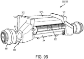
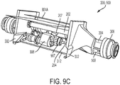
- FIGs. 9B and 9C depict the front axle assembly 300, 500 for the dual front wheel combine 100 with the fan 922 and a transmission 906 mounted to the rigid front axle assembly 500.
- the transmission 906 for moving the planetary final drives 306 (and, thus, the wheels 124 of the combine 100) is mounted to the rear side of the bracket 207.
- Shafts 907 (one shown) extending from the both sides of the transmission 906 are either directly or indirectly connected to the planetary final drives 306.
- Replacing a large solid axle with the two tubes 202 and 204 provides clearance space for accommodating at least a portion of the transmission 906 in the space previously occupied by a large solid axle.
- the fan 922 is at least partially positioned between the tubes 202, 204 and mounted both to and between the wheel support members 302.
- the lower duct wall 924A in the form of a sheet, is also mounted to the wheel support members 302 for directing the air produced by the fan 922 over the top tube 202 toward the cleaning system 900 of the combine 100.
- Replacing a large solid axle with the two tubes 202 and 204 provides clearance space for accommodating at least a portion of the fan 922.
- Various other components may be connected to the brackets 206 and 207 and wheel support members 302.
- pre-blower fan 902, duct 904, and transmission 906 may be mounted in a similar manner to any of the combine sub-assemblies described herein and shown in FIGs. 3A-8 .
- each front axle assembly described herein includes the same axle 200. Modularizing the axle 200 such that it accommodates a large variety of combine styles is advantageous from the inventory and cost perspectives.
Landscapes
- Engineering & Computer Science (AREA)
- Mechanical Engineering (AREA)
- Life Sciences & Earth Sciences (AREA)
- Environmental Sciences (AREA)
- Chemical & Material Sciences (AREA)
- Combustion & Propulsion (AREA)
- Transportation (AREA)
- Harvester Elements (AREA)
- Tires In General (AREA)
- Combines (AREA)
Description
- The present invention relates to a rigid axle for a combine harvester.
- Many agricultural operators desire combines that have greater harvesting and grain processing and handling capacity. One way to increase harvesting and grain processing and handling capacity is to add an additional cleaning fan, which may also be referred to herein as a pre-blower, at or near the front axle of the combine. The pre-blower is used to generate a rearwardly directed flow of air to sieves of a cleaning system for removing material other than grain from the grain itself before it is conveyed to the grain tank or offloaded.
- Adding the pre-blower at or near the front axle of the combine presents a substantial design challenge because a standard rigid front axle cannot accommodate the physical envelope of the pre-blower. Thus, the front axle must be modified to accommodate the physical envelope of the pre-blower. The front axle must be modified because it is not possible to simply increase the overall size envelope of the combine. The overall size envelope of the combine is limited by width restrictions for passage over public roads, thoroughfares, bridges and the like, by height restrictions for passage under overhead wires and through doors of storage and service buildings, and trailer transport restrictions.
- As another challenge, there are a variety of different combine models (e.g., single wheel (one wheel on each side of the axle), dual wheel, tracks, etc. , and it would beneficial from the cost and inventory perspectives to have one axle structure that is capable of being employed in all of those different combine models.
- What is sought is a light-weight rigid axle for a combine that will (i) accommodate the physical envelope of the additional cleaning fan, (ii) work with the variety of different combine styles, and (iii) safely and durably support the weight of the combine machine.
US 6 206 125 B1 describes an apparatus and method for locking an adjustable width axle assembly of a crop sprayer.US 2014/260158 A1 describes a combine harvester having a rear axle that can be extended to facilitate steering of the harvester. -
GB 2 024 595 A -
US 9 750 192 B2 - Described herein is a modular axle assembly for supporting the wheels of an agricultural vehicle. The wheels may be wheels having pneumatic tires or wheels for driving an endless track. The modular axle assembly may be used with a variety of agricultural vehicles, not limited to a single or dual front wheel combine and a front track combine. The modular axle assembly accommodates different variations of feeder pivot locations, feeder lengths and lift geometry.
- More particularly, according to one aspect of the invention, a modular axle assembly according to claim 1 is disclosed.
- According to another aspect of the invention, a combine harvester according to claim 10 is disclosed.
- The above-mentioned and other features and advantages of this invention, and the manner of attaining them, will become more apparent and the invention will be better understood by reference to the following description of an embodiment of the invention taken in conjunction with the accompanying drawings, wherein:
-
FIG. 1 is a schematic view of a combine harvester. -
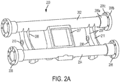
FIG. 2A is an isometric view of the front facing side of a rigid and modular front axle of the combine. -
FIG. 2B is an isometric view of the rear facing side of the front axle ofFIG. 2A . -
FIG. 3A depicts an isometric front view of a front axle assembly, shown exploded, for a dual front wheel combine. -
FIG. 3B depicts an isometric rear view of the front axle assembly ofFIG. 3A . -
FIG. 4 depicts an isometric front view of a front axle assembly, shown exploded, for another dual wheel combine. -
FIG. 5 depicts an isometric front view of a front axle assembly, shown exploded, for yet another dual wheel combine. -
FIG. 6 depicts an isometric front view of a front axle assembly, shown exploded, for a front track combine. -
FIG. 7 depicts an isometric front view of a front axle assembly, shown exploded, for another front track combine. -
FIG. 8 depicts an isometric front view of a front axle assembly, shown exploded, for yet another front track combine. -
FIG. 9A illustrates a cross-sectional view of a cleaning system of a combine harvester, the combine harvester comprising the front axle assembly ofFIG. 5 and at least one fan system. -
FIG. 9B is an isometric front view of the front axle assembly ofFIG. 5 in the combine harvester shown with a transmission and the at least one fan system ofFIG. 9A . -
FIG. 9C is an isometric rear view of the front axle assembly shown inFIG. 9B . - Corresponding reference characters indicate corresponding parts throughout the several views. The exemplification set out herein illustrates an embodiment of the invention, in one form, and such exemplification is not to be construed as limiting the scope of the invention in any manner.
- The terms "forward", "rearward", "left" and "right", when used in connection with the agricultural harvester and/or components thereof are usually determined with reference to the direction of forward operative travel of the harvester, but again, they should not be construed as limiting. The terms "longitudinal" and "transverse" are determined with reference to the fore-and-aft direction of the agricultural harvester and are equally not to be construed as limiting.
- Referring now to the drawings, in
FIG. 1 , a combine harvester 100 (hereinafter also referred to as "combine 100") is shown including a rigid axle structure 200 (referred to hereinafter as axle 200) to which drivewheels 124 are connected. Apre-blower cleaning fan 116 is mounted to theaxle 200 for blowing a flow of air upwardly and rearwardly, as denoted by arrows inFIG. 1 , through sieves of acleaning system 118 of thecombine 100. Thecleaning system 118 is operable in the well-known manner for separating material other than grain from grain harvested by combine 100. Afeeder 126 is connected to the front end of thecombine 100 for delivering crop material into thethreshing system 128 of thecombine 100. - The forward and mid portions of the
combine 100 are illustrated inFIG. 1 , and it is contemplated that theaxle 200 is preferably configured for use in connection with forwardly located drive wheels of a combine, although the present invention is not intended to be limited by that application. Other details of thecombine 100 are disclosed inU.S. Patent No. 7,670,219 , which is incorporated by reference herein in its entirety. - Referring now to
FIGs. 2A and2B , theaxle 200 generally comprises anupper tube 202 that is mounted to alower tube 204 by a series ofbrackets tube tubes - It should be understood that neither the
axle 200 nor itstubes axle 200 is stationary and rigid during operation. However, according to a different embodiment, the tubes may be rotatable shafts. - A hollow
cylindrical flange 208 is mounted to each end of each of thetubes flange 208 includes a hollowsmall diameter portion 208a for fitting over the end of atube small diameter portion 208a may be connected to thetube flange 208 also includes alarge diameter portion 208b havingtransverse holes 208c that pass there through. Fasteners (not shown) pass through theholes 208c for fastening thelarge diameter portion 208b of theflange 208 to another component that is mated to theaxle 200. - The
brackets 206 connect thetubes tubes bracket 206 are fixed to thetubes bracket 206 comprises two V-shapedplates 209 that are spaced apart by a predetermined distance. Anopening 213 is disposed in eachplate 209. Asupport member 211 is positioned between theadjacent plates 209. - The
bracket 207 is box shaped, and also connects thetubes bracket 207 is positioned between thebrackets 206. The ends of thebracket 207 are fixed to thetubes bracket 207 is rounded to conform to the cylindrical body of thetube 202. Similarly, the bottom surface of thebracket 207 is rounded to conform to the cylindrical body of thetube 204. - A transmission for moving the
wheels 124 of thecombine 100 may be connected to thebracket 207, as is disclosed inU.S. Patent No. 7,670,219 and shown inFIG. 9B . - As shown in
FIG. 9A , a pre-blower 922 may be at least partially positioned between thetubes tubes brackets - The
axle 200 is a modular base unit meaning that a variety of components can be connected, either directly or indirectly, to theaxle 200 in order to form different front axle assemblies. Various front axle assemblies are described hereinafter, each of which incorporates themodular axle 200. - The
axle 200 is a light-weight rigid axle for a combine that will (i) accommodate the physical envelope of the additional cleaning fan, (ii) work with the variety of different combine styles, and (iii) safely and durably support the weight of the combine machine. -
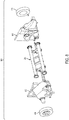
FIGs. 3A and3B depicts a rigidfront axle assembly 300 for a dual front wheel combine. The rigidfront axle assembly 300 comprises theaxle 200. -
Mounts 310 are fixed to opposing ends of thelower tube 204 of theaxle 200. According to one exemplary embodiment, eachmount 310 comprises two triangular shapedflanges 311 that extend forward of thetube 204, and includeopenings 305 defined therethrough. Theflanges 311 are welded (or otherwise fixedly mounted) to thetube 204. Aplate 313 is mounted to the lower edge of theadjacent flanges 311. Themounts 310 provide a suitable jacking or cribbing location for the combine. - Although not shown, hydraulic cylinders (not shown) extending from the
feeder 126 are releasably connected to theopenings 305 in therespective mounts 310 for pivoting thefeeder 126 with respect to the combine. The interconnection between a hydraulic cylinder, a feeder and a combine axle is shown inU.S. Patent No. 8726622 , which is incorporated by reference in its entirety. As will be described in detail later, the structure of each mount can vary. - On each side of the
axle 200, awheel support member 302 is bolted (or otherwise mounted) to both of thetubes axle 200, anaxle extension 304 is bolted (or otherwise mounted) to a laterally outwardly face of thewheel support member 302, and a planetaryfinal drive 306 is bolted (or otherwise mounted) to a laterally outwardly face of theaxle extension 304. - Each planetary final drive includes a
rotating plate 308. Although not shown, two front wheels are mounted to eachplate 308 such that theaxle assembly 300 supports a total of four front wheels. According to this exemplary embodiment, thefinal drive 306 is a planetary final drive, however, thefinal drive 306 could be a bull gear final drive, an electric motor, a hydraulic motor, a pneumatic motor, or another other type of final drive known to those skilled in the art. - The
wheel support member 302 is mounted to the frame of the combine and is a structural member of the combine to which other components are mounted. Thewheel support member 302 includesflange mounting areas tubes - A
tie rod 312 is a rigid member having opposite ends, each end being mounted to one of thewheel support members 302. Like thetubes tie rod 312 provides structural stability and rigidity to theaxle assembly 300. Thetubes tie rod 312 are oriented in a triangular fashion (as viewed from the side of the axle assembly 300). Although not shown, each of the axle assemblies described hereinafter may include atie rod 312. Thetie rod 312 is an optional component and may be omitted. - The
axle extensions 304 provide added length to each side of theaxle assembly 300 such that two wheels can be mounted to each side of the axle assembly. If, however, only a single front wheel is mounted to each side of theaxle 200, then bothaxle extensions 304 may be omitted, and the planetaryfinal drives 306 may be mounted directly to respectivewheel support members 302. - As will be described with reference to
FIGs. 9B and9C , an output shaft of the transmission is coupled to both of the planetaryfinal drives 306. In operation, the transmission rotates theplates 308 of the planetaryfinal drives 306 for driving all four front wheels. It should be understood that thewheel support member 302 and theaxle extension 304 remain stationary in operation. -
FIG. 4 depicts a rigidfront axle assembly 400 for another dual front wheel combine. The primary difference between thefront axle assemblies axle 200 of thefront axle assembly 400 includesdifferent mounts 410. Themounts 410 provide a suitable jacking or cribbing location. Themounts 410 are configured for connecting to the hydraulic cylinders of a feeder of the combine. It is envisioned that themounts -
FIG. 5 depicts a rigidfront axle assembly 500 for yet another dual front wheel combine. The primary difference between thefront axle assemblies front axle assembly 500 are not shown. The mounts for thefront axle assembly 500 may form part of the feeder of the combine. -
FIG. 6 depicts a rigidfront axle assembly 600 for a front track combine. The rigidfront axle assembly 600 comprises theaxle 200 havingmounts 310. The features of theaxle 200 and themounts 310 are described above. - On each side of the
axle 200, awheel support member 602 is bolted (or otherwise mounted) to both of thetubes axle 200, and a bull gearfinal drive 604 is bolted (or otherwise mounted) to an outwardly facing side of thewheel support member 602. - The
track support member 602 is mounted to the frame of the combine and is a structural member of the combine to which other components are mounted.Travel limiters 603 protrude outwardly from eachtrack support member 602 to limit rotation of the track assemblies with respect to theaxle 200. - Each bull gear
final drive 604 includes arotating plate 606. Although not shown, a wheel is mounted to theplate 606, and that wheel spins an endless track. A representative endless track is disclosed inU.S. Patent No. 6,929,334 , which is incorporated by reference herein in its entirety and for all purposes. -
Rotatable output shafts 607 extending from the transmission (not shown in this figure) are physically coupled to the bull gear final drives 604. In operation, the transmission rotates theshafts 607, and eachshaft 607 rotates aninput shaft 608 of the bull gearfinal drive 604, which rotates theplate 606. Rotation of theplate 606 causes rotation of the endless track that is indirectly connected to theplate 606. It should be understood that thetrack support member 602 remains stationary during operation. -
FIG. 7 depicts a rigidfront axle assembly 700 for another front track combine. The primary difference between thefront axle assemblies axle 200 of thefront axle assembly 700 includes themounts 410 instead of themounts 310. As noted above, themounts 410 are configured for connecting to the hydraulic cylinders of the feeder of the combine. -
FIG. 8 depicts a rigidfront axle assembly 800 for yet another front track combine. The primary difference between thefront axle assemblies front axle assembly 800 are not shown. The mounts for thefront axle assembly 800 may form part of the feeder of the combine. - Referring now to
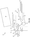
FIG. 9A , there is illustrated acleaning system 900 and a threshingsystem 940 for thecombine 100, in accordance with an exemplary embodiment of the present invention. Thecleaning system 900 comprises acleaning shoe 910, afirst blower assembly 920, and asecond blower assembly 930. Thecleaning shoe 910 comprises agrain pan 912, a pre-sieve 914, a chaffer orupper sieve 916, and alower sieve 918. Thegrain pan 912 receives grain and material other than grain ("MOG") from an anterior portion of the threshingsystem 940, and the pre-sieve 914 receives grain and MOG from a posterior portion of the threshingsystem 940. Thecleaning system 910 separates grain from MOG. - The
first blower assembly 920 comprises afan 922 and anoutlet duct 924 formed from at least alower sheet 924A and anupper sheet 924B. Thefirst blower assembly 920 is configured to blow air into thecleaning shoe 910 to facilitate the separation of grain from MOG. - The
second blower assembly 930 comprises afan 932 andoutlet ducts second blower assembly 930 is configured to blow air into thecleaning shoe 910 to facilitate the separation of grain from MOG. - The
first blower assembly 920 is configured to blow air into thecleaning shoe 910 upstream from thesecond blower assembly 930. Specifically, thefan 922 and theduct 924 direct air near thegrain pan 912, theduct 934 is configured to direct air from thefan 932 to an area above the pre-sieve 914, and theduct 936 is configured to direct air from thefan 932 through the pre-sieve 914. Theducts cleaning shoe 910 downstream from thegrain pan 912. - The
first blower assembly 920, specifically thefan 922, is positioned so that at least a portion of thefirst blower assembly 920, specifically at least a portion of thefan 922, is disposed between thetubes tube 202 comprises alongitudinal axis 202A, and thetube 204 comprises alongitudinal axis 204A. In an exemplary embodiment, at least a downstream andinnermost point 925A of anouter periphery 925 of thefan 922 is disposed between avertical plane 902 passing throughlongitudinal axis 202A and avertical plane 904 passing through thelongitudinal axis 204A. The placement of thefirst blower assembly 920, specifically thefan 922, at theaxle 200 provides for the ability to include thefirst blower assembly 920 in thecombine 100 and for more flexibility in the placement of theduct 924. - In an exemplary embedment, the
first blower assembly 920 is a pre-blower assembly in which thefan 922 is a pre-blower for fluidizing the grain and MOG mat on thegrain pan 912 or coming off thegrain pan 912. In such embodiment, thesecond blower assembly 930 is a primary blower assembly, and thefan 932 is a primary fan. Other embodiments of thecleaning system 900 in which only thefirst blower assembly 920 is present are contemplated. In such other exemplary embodiments, theduct 924 may be directed to direct air to other portions of the cleaningassembly 900. In an exemplary embodiment, thefan 922 is a cross-flow fan. -
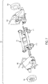
FIGs. 9B and9C depict thefront axle assembly fan 922 and atransmission 906 mounted to the rigidfront axle assembly 500. - More specifically, the
transmission 906 for moving the planetary final drives 306 (and, thus, thewheels 124 of the combine 100) is mounted to the rear side of thebracket 207. Shafts 907 (one shown) extending from the both sides of thetransmission 906 are either directly or indirectly connected to the planetaryfinal drives 306. Replacing a large solid axle with the twotubes transmission 906 in the space previously occupied by a large solid axle. - The
fan 922 is at least partially positioned between thetubes wheel support members 302. As seen inFIG. 9B , thelower duct wall 924A, in the form of a sheet, is also mounted to thewheel support members 302 for directing the air produced by thefan 922 over thetop tube 202 toward thecleaning system 900 of thecombine 100. Replacing a large solid axle with the twotubes fan 922. Various other components may be connected to thebrackets wheel support members 302. - It should be understood that the
pre-blower fan 902,duct 904, andtransmission 906 may be mounted in a similar manner to any of the combine sub-assemblies described herein and shown inFIGs. 3A-8 . - It can be appreciated that each front axle assembly described herein includes the
same axle 200. Modularizing theaxle 200 such that it accommodates a large variety of combine styles is advantageous from the inventory and cost perspectives. - While this invention has been described with respect to at least one embodiment, the present invention can be further modified within the scope of this disclosure. This application is therefore intended to cover any variations, uses, or adaptations of the invention using its general principles. Further, this application is intended to cover such departures from the present disclosure as come within known or customary practice in the art to which this invention pertains and which fall within the limits of the appended claims.
Claims (10)
- A modular axle assembly (200) for supporting wheels of an agricultural vehicle, said modular axle assembly comprising:a first tube (202);a second tube (204) parallel to the first tube (202);at least one bracket (207) connecting the first tube (202) and the second tube (204); anda first wheel support (302) member mounted to first ends of the first tube (202) and the second tube (204) and a second wheel support member (302) mounted to second ends of the first tube (202) and the second tube (204),characterized in that the modular axle assembly further comprises a fan (922) mounted to the wheel support members (302) and positioned at least partially between the tubes (202, 204).
- The modular axle assembly of claim 1 characterized in that the modular axle assembly further comprises a transmission (906) mounted to the bracket (207) for powering wheels of the agricultural vehicle, the transmission being positioned at least partially between the tubes (202, 204).
- The modular axle assembly of claim 1 or 2, characterized in that the fan (922) has an outer periphery (925) having a point (925A) that is disposed between longitudinal axes (202A, 204A) of the first and second tubes (202, 204).
- The modular axle assembly of claim 1 or 2, characterized in that each wheel support member (302) is mounted to one of a planetary final drive (306) and a bull gear final drive (604), wherein said one of the planetary final drive (306) and the bull gear final drive (604) is configured to be connected to a wheel of the agricultural vehicle.
- The modular axle assembly of claim 4, characterized in that said one of the planetary final drive (306) and the bull gear final drive is mounted to one side of the wheel support member, and the first and second tubes are mounted to an opposite side of the wheel support member.
- The modular axle assembly of claim 1 or 2, characterized in that each end of the first tube (202) and the second tube (204) includes a flange (208), and each flange (208) is mounted to one of the wheel support members (302).
- The modular axle assembly of any of the foregoing claims characterized in that the modular axle assembly further comprises mounts (310) connected to the first tube (202) that are configured to be connected to a feeder of the agricultural vehicle.
- The modular axle assembly of any of the foregoing claims, characterized in that each tube (202, 204) is either hollow or solid.
- The modular axle assembly of any of the foregoing claims characterized in that the modular axle assembly further comprises two additional brackets (206) connecting the first tube (202) and the second tube (204), said at least one bracket (207) positioned between the additional brackets (206) along a length dimension of the first tube (202) and the second tube (204).
- A combine harvester comprising a front axle assembly (200) according to any of the preceding claims, further comprising:at least two wheels connected to the front axle assembly (200); anda cleaning system (900) comprising:a cleaning shoe (910); andthe fan (922) mounted to the front axle assembly (200) and positioned at least partially between the first tube (202) and the second tube (204), the fan (922) being configured for delivering air into the cleaning shoe (910).
Applications Claiming Priority (1)
| Application Number | Priority Date | Filing Date | Title |
|---|---|---|---|
| US15/938,124 US10791676B2 (en) | 2018-03-28 | 2018-03-28 | Modular combine traction axle |
Publications (3)
| Publication Number | Publication Date |
|---|---|
| EP3545751A2 EP3545751A2 (en) | 2019-10-02 |
| EP3545751A3 EP3545751A3 (en) | 2019-11-06 |
| EP3545751B1 true EP3545751B1 (en) | 2021-01-27 |
Family
ID=65991686
Family Applications (1)
| Application Number | Title | Priority Date | Filing Date |
|---|---|---|---|
| EP19165349.2A Active EP3545751B1 (en) | 2018-03-28 | 2019-03-26 | Modular combine traction axle |
Country Status (2)
| Country | Link |
|---|---|
| US (1) | US10791676B2 (en) |
| EP (1) | EP3545751B1 (en) |
Family Cites Families (13)
| Publication number | Priority date | Publication date | Assignee | Title |
|---|---|---|---|---|
| DE2830069A1 (en) | 1978-07-08 | 1980-01-17 | Deere & Co | Combine harvester that works according to the axial flow principle |
| US6206125B1 (en) | 2000-02-02 | 2001-03-27 | Equipment Technologies, Inc. | Apparatus and method for locking an adjustable width axle assembly of a crop sprayer |
| GB2388347A (en) | 2002-05-11 | 2003-11-12 | Ford New Holland Nv | Endless track tension system |
| US7585032B2 (en) | 2003-10-17 | 2009-09-08 | American Axle & Manufacturing, Inc. | Modular axle assembly |
| DE102004041427A1 (en) | 2004-08-27 | 2006-03-02 | Daimlerchrysler Ag | Vehicle axle with integrated spring brackets |
| US7559403B2 (en) | 2006-04-05 | 2009-07-14 | Schmitz Geoffrey W | Modular, central frame, offset, dual control arm independent suspension and suspension retrofit |
| US7670219B2 (en) | 2006-12-13 | 2010-03-02 | Cnh America Llc | Integrated axle and cleaning fan wrapper for an agricultural harvesting machine |
| CN101808842B (en) | 2007-09-27 | 2013-10-23 | 美国轮轴制造公司 | Motorcycle axle assembly |
| US8464611B1 (en) | 2009-05-20 | 2013-06-18 | Ira Chandler | Modular and adjustable axle systems for vehicles |
| US8726622B2 (en) | 2010-12-16 | 2014-05-20 | Cnh Industrial America Llc | Feeder arm safety stand |
| CN103029577B (en) | 2012-12-28 | 2015-09-09 | 辽宁曙光汽车集团股份有限公司 | The coaxial associated mode driving axis of electronlmobil |
| US20140260158A1 (en) | 2013-03-13 | 2014-09-18 | Agco Corporation | Harvester with extendable rear axle |
| US9750192B2 (en) | 2014-08-29 | 2017-09-05 | Deere & Company | Integrated fan and axle arrangement for an agricultural vehicle |
-
2018
- 2018-03-28 US US15/938,124 patent/US10791676B2/en active Active
-
2019
- 2019-03-26 EP EP19165349.2A patent/EP3545751B1/en active Active
Non-Patent Citations (1)
| Title |
|---|
| None * |
Also Published As
| Publication number | Publication date |
|---|---|
| EP3545751A2 (en) | 2019-10-02 |
| EP3545751A3 (en) | 2019-11-06 |
| US20190297779A1 (en) | 2019-10-03 |
| US10791676B2 (en) | 2020-10-06 |
| BR102019006142A2 (en) | 2019-10-22 |
Similar Documents
| Publication | Publication Date | Title |
|---|---|---|
| EP3395156B1 (en) | An agricultural harvesting head with a gauge and transport wheel arrangement | |
| EP1932421B1 (en) | Integrated axle and cleaning fan wrapper for an agricultural harvesting machine | |
| CA2400901C (en) | Foldable harvesting header | |
| CA2521892C (en) | Rotor for a straw chopper | |
| US5865444A (en) | Body leveling suspension including a pivoting arrangement | |
| EP3406130B1 (en) | Agricultural machine with sectional header | |
| US10080329B2 (en) | Side shaker link for agricultural harvester sieve assembly | |
| EP2992752B1 (en) | Integrated fan and axle arrangement for an agricultural vehicle | |
| GB1560593A (en) | Self-propelled crop harvester | |
| EP3545751B1 (en) | Modular combine traction axle | |
| US9469342B2 (en) | Axle and transmission arrangement for an agricultural vehicle | |
| BR102016024492A2 (en) | sieve assembly for a farm harvester and farm harvester | |
| US10375884B2 (en) | Self-propelled harvester with front access to crop processing apparatus | |
| BR102019006142B1 (en) | MODULAR AXLE ASSEMBLY FOR SUPPORTING WHEELS OF AN AGRICULTURAL VEHICLE AND HARVESTING MACHINE COMPRISING A FRONT AXLE ASSEMBLY | |
| JP6257479B2 (en) | Combine | |
| US6978588B2 (en) | Harvesting machine | |
| US20230413726A1 (en) | Cleaning assembly for a combine harvester | |
| USRE26512E (en) | Mounting and dismounting means for agricultural machines | |
| CA1160060A (en) | Push-type swather attachments | |
| JPH1191385A (en) | Work machine wheel support structure | |
| DE102019215143A1 (en) | Forage harvester with two-part transition housing | |
| JPH11137058A (en) | Combine traveling equipment |
Legal Events
| Date | Code | Title | Description |
|---|---|---|---|
| PUAI | Public reference made under article 153(3) epc to a published international application that has entered the european phase |
Free format text: ORIGINAL CODE: 0009012 |
|
| STAA | Information on the status of an ep patent application or granted ep patent |
Free format text: STATUS: THE APPLICATION HAS BEEN PUBLISHED |
|
| AK | Designated contracting states |
Kind code of ref document: A2 Designated state(s): AL AT BE BG CH CY CZ DE DK EE ES FI FR GB GR HR HU IE IS IT LI LT LU LV MC MK MT NL NO PL PT RO RS SE SI SK SM TR |
|
| AX | Request for extension of the european patent |
Extension state: BA ME |
|
| PUAL | Search report despatched |
Free format text: ORIGINAL CODE: 0009013 |
|
| AK | Designated contracting states |
Kind code of ref document: A3 Designated state(s): AL AT BE BG CH CY CZ DE DK EE ES FI FR GB GR HR HU IE IS IT LI LT LU LV MC MK MT NL NO PL PT RO RS SE SI SK SM TR |
|
| AX | Request for extension of the european patent |
Extension state: BA ME |
|
| RIC1 | Information provided on ipc code assigned before grant |
Ipc: A01F 12/44 20060101AFI20190930BHEP Ipc: B60B 35/16 20060101ALN20190930BHEP Ipc: B60B 35/14 20060101ALI20190930BHEP Ipc: A01D 67/00 20060101ALI20190930BHEP |
|
| STAA | Information on the status of an ep patent application or granted ep patent |
Free format text: STATUS: REQUEST FOR EXAMINATION WAS MADE |
|
| 17P | Request for examination filed |
Effective date: 20200506 |
|
| RBV | Designated contracting states (corrected) |
Designated state(s): AL AT BE BG CH CY CZ DE DK EE ES FI FR GB GR HR HU IE IS IT LI LT LU LV MC MK MT NL NO PL PT RO RS SE SI SK SM TR |
|
| RIC1 | Information provided on ipc code assigned before grant |
Ipc: B60B 35/16 20060101ALN20200714BHEP Ipc: A01D 67/00 20060101ALI20200714BHEP Ipc: B60B 35/14 20060101ALI20200714BHEP Ipc: A01F 12/44 20060101AFI20200714BHEP |
|
| GRAP | Despatch of communication of intention to grant a patent |
Free format text: ORIGINAL CODE: EPIDOSNIGR1 |
|
| STAA | Information on the status of an ep patent application or granted ep patent |
Free format text: STATUS: GRANT OF PATENT IS INTENDED |
|
| RIC1 | Information provided on ipc code assigned before grant |
Ipc: B60B 35/14 20060101ALI20200720BHEP Ipc: B60B 35/16 20060101ALN20200720BHEP Ipc: A01F 12/44 20060101AFI20200720BHEP Ipc: A01D 67/00 20060101ALI20200720BHEP |
|
| INTG | Intention to grant announced |
Effective date: 20200825 |
|
| GRAS | Grant fee paid |
Free format text: ORIGINAL CODE: EPIDOSNIGR3 |
|
| GRAA | (expected) grant |
Free format text: ORIGINAL CODE: 0009210 |
|
| STAA | Information on the status of an ep patent application or granted ep patent |
Free format text: STATUS: THE PATENT HAS BEEN GRANTED |
|
| AK | Designated contracting states |
Kind code of ref document: B1 Designated state(s): AL AT BE BG CH CY CZ DE DK EE ES FI FR GB GR HR HU IE IS IT LI LT LU LV MC MK MT NL NO PL PT RO RS SE SI SK SM TR |
|
| REG | Reference to a national code |
Ref country code: GB Ref legal event code: FG4D |
|
| REG | Reference to a national code |
Ref country code: CH Ref legal event code: EP |
|
| REG | Reference to a national code |
Ref country code: AT Ref legal event code: REF Ref document number: 1357499 Country of ref document: AT Kind code of ref document: T Effective date: 20210215 |
|
| REG | Reference to a national code |
Ref country code: IE Ref legal event code: FG4D |
|
| REG | Reference to a national code |
Ref country code: DE Ref legal event code: R096 Ref document number: 602019002313 Country of ref document: DE |
|
| REG | Reference to a national code |
Ref country code: NL Ref legal event code: MP Effective date: 20210127 |
|
| REG | Reference to a national code |
Ref country code: LT Ref legal event code: MG9D |
|
| REG | Reference to a national code |
Ref country code: AT Ref legal event code: MK05 Ref document number: 1357499 Country of ref document: AT Kind code of ref document: T Effective date: 20210127 |
|
| PG25 | Lapsed in a contracting state [announced via postgrant information from national office to epo] |
Ref country code: BG Free format text: LAPSE BECAUSE OF FAILURE TO SUBMIT A TRANSLATION OF THE DESCRIPTION OR TO PAY THE FEE WITHIN THE PRESCRIBED TIME-LIMIT Effective date: 20210427 Ref country code: HR Free format text: LAPSE BECAUSE OF FAILURE TO SUBMIT A TRANSLATION OF THE DESCRIPTION OR TO PAY THE FEE WITHIN THE PRESCRIBED TIME-LIMIT Effective date: 20210127 Ref country code: GR Free format text: LAPSE BECAUSE OF FAILURE TO SUBMIT A TRANSLATION OF THE DESCRIPTION OR TO PAY THE FEE WITHIN THE PRESCRIBED TIME-LIMIT Effective date: 20210428 Ref country code: FI Free format text: LAPSE BECAUSE OF FAILURE TO SUBMIT A TRANSLATION OF THE DESCRIPTION OR TO PAY THE FEE WITHIN THE PRESCRIBED TIME-LIMIT Effective date: 20210127 Ref country code: LT Free format text: LAPSE BECAUSE OF FAILURE TO SUBMIT A TRANSLATION OF THE DESCRIPTION OR TO PAY THE FEE WITHIN THE PRESCRIBED TIME-LIMIT Effective date: 20210127 Ref country code: PT Free format text: LAPSE BECAUSE OF FAILURE TO SUBMIT A TRANSLATION OF THE DESCRIPTION OR TO PAY THE FEE WITHIN THE PRESCRIBED TIME-LIMIT Effective date: 20210527 Ref country code: NO Free format text: LAPSE BECAUSE OF FAILURE TO SUBMIT A TRANSLATION OF THE DESCRIPTION OR TO PAY THE FEE WITHIN THE PRESCRIBED TIME-LIMIT Effective date: 20210427 |
|
| PG25 | Lapsed in a contracting state [announced via postgrant information from national office to epo] |
Ref country code: SE Free format text: LAPSE BECAUSE OF FAILURE TO SUBMIT A TRANSLATION OF THE DESCRIPTION OR TO PAY THE FEE WITHIN THE PRESCRIBED TIME-LIMIT Effective date: 20210127 Ref country code: LV Free format text: LAPSE BECAUSE OF FAILURE TO SUBMIT A TRANSLATION OF THE DESCRIPTION OR TO PAY THE FEE WITHIN THE PRESCRIBED TIME-LIMIT Effective date: 20210127 Ref country code: PL Free format text: LAPSE BECAUSE OF FAILURE TO SUBMIT A TRANSLATION OF THE DESCRIPTION OR TO PAY THE FEE WITHIN THE PRESCRIBED TIME-LIMIT Effective date: 20210127 Ref country code: RS Free format text: LAPSE BECAUSE OF FAILURE TO SUBMIT A TRANSLATION OF THE DESCRIPTION OR TO PAY THE FEE WITHIN THE PRESCRIBED TIME-LIMIT Effective date: 20210127 Ref country code: AT Free format text: LAPSE BECAUSE OF FAILURE TO SUBMIT A TRANSLATION OF THE DESCRIPTION OR TO PAY THE FEE WITHIN THE PRESCRIBED TIME-LIMIT Effective date: 20210127 |
|
| PG25 | Lapsed in a contracting state [announced via postgrant information from national office to epo] |
Ref country code: IS Free format text: LAPSE BECAUSE OF FAILURE TO SUBMIT A TRANSLATION OF THE DESCRIPTION OR TO PAY THE FEE WITHIN THE PRESCRIBED TIME-LIMIT Effective date: 20210527 |
|
| REG | Reference to a national code |
Ref country code: DE Ref legal event code: R097 Ref document number: 602019002313 Country of ref document: DE |
|
| PG25 | Lapsed in a contracting state [announced via postgrant information from national office to epo] |
Ref country code: EE Free format text: LAPSE BECAUSE OF FAILURE TO SUBMIT A TRANSLATION OF THE DESCRIPTION OR TO PAY THE FEE WITHIN THE PRESCRIBED TIME-LIMIT Effective date: 20210127 Ref country code: CZ Free format text: LAPSE BECAUSE OF FAILURE TO SUBMIT A TRANSLATION OF THE DESCRIPTION OR TO PAY THE FEE WITHIN THE PRESCRIBED TIME-LIMIT Effective date: 20210127 Ref country code: MC Free format text: LAPSE BECAUSE OF FAILURE TO SUBMIT A TRANSLATION OF THE DESCRIPTION OR TO PAY THE FEE WITHIN THE PRESCRIBED TIME-LIMIT Effective date: 20210127 Ref country code: SM Free format text: LAPSE BECAUSE OF FAILURE TO SUBMIT A TRANSLATION OF THE DESCRIPTION OR TO PAY THE FEE WITHIN THE PRESCRIBED TIME-LIMIT Effective date: 20210127 |
|
| PG25 | Lapsed in a contracting state [announced via postgrant information from national office to epo] |
Ref country code: RO Free format text: LAPSE BECAUSE OF FAILURE TO SUBMIT A TRANSLATION OF THE DESCRIPTION OR TO PAY THE FEE WITHIN THE PRESCRIBED TIME-LIMIT Effective date: 20210127 Ref country code: SK Free format text: LAPSE BECAUSE OF FAILURE TO SUBMIT A TRANSLATION OF THE DESCRIPTION OR TO PAY THE FEE WITHIN THE PRESCRIBED TIME-LIMIT Effective date: 20210127 Ref country code: DK Free format text: LAPSE BECAUSE OF FAILURE TO SUBMIT A TRANSLATION OF THE DESCRIPTION OR TO PAY THE FEE WITHIN THE PRESCRIBED TIME-LIMIT Effective date: 20210127 |
|
| PLBE | No opposition filed within time limit |
Free format text: ORIGINAL CODE: 0009261 |
|
| STAA | Information on the status of an ep patent application or granted ep patent |
Free format text: STATUS: NO OPPOSITION FILED WITHIN TIME LIMIT |
|
| REG | Reference to a national code |
Ref country code: BE Ref legal event code: MM Effective date: 20210331 |
|
| 26N | No opposition filed |
Effective date: 20211028 |
|
| PG25 | Lapsed in a contracting state [announced via postgrant information from national office to epo] |
Ref country code: ES Free format text: LAPSE BECAUSE OF FAILURE TO SUBMIT A TRANSLATION OF THE DESCRIPTION OR TO PAY THE FEE WITHIN THE PRESCRIBED TIME-LIMIT Effective date: 20210127 Ref country code: AL Free format text: LAPSE BECAUSE OF FAILURE TO SUBMIT A TRANSLATION OF THE DESCRIPTION OR TO PAY THE FEE WITHIN THE PRESCRIBED TIME-LIMIT Effective date: 20210127 Ref country code: LU Free format text: LAPSE BECAUSE OF NON-PAYMENT OF DUE FEES Effective date: 20210326 Ref country code: IE Free format text: LAPSE BECAUSE OF NON-PAYMENT OF DUE FEES Effective date: 20210326 |
|
| PG25 | Lapsed in a contracting state [announced via postgrant information from national office to epo] |
Ref country code: SI Free format text: LAPSE BECAUSE OF FAILURE TO SUBMIT A TRANSLATION OF THE DESCRIPTION OR TO PAY THE FEE WITHIN THE PRESCRIBED TIME-LIMIT Effective date: 20210127 |
|
| PG25 | Lapsed in a contracting state [announced via postgrant information from national office to epo] |
Ref country code: IS Free format text: LAPSE BECAUSE OF FAILURE TO SUBMIT A TRANSLATION OF THE DESCRIPTION OR TO PAY THE FEE WITHIN THE PRESCRIBED TIME-LIMIT Effective date: 20210527 |
|
| PG25 | Lapsed in a contracting state [announced via postgrant information from national office to epo] |
Ref country code: BE Free format text: LAPSE BECAUSE OF NON-PAYMENT OF DUE FEES Effective date: 20210331 |
|
| REG | Reference to a national code |
Ref country code: CH Ref legal event code: PL |
|
| PG25 | Lapsed in a contracting state [announced via postgrant information from national office to epo] |
Ref country code: LI Free format text: LAPSE BECAUSE OF NON-PAYMENT OF DUE FEES Effective date: 20220331 Ref country code: CH Free format text: LAPSE BECAUSE OF NON-PAYMENT OF DUE FEES Effective date: 20220331 |
|
| PG25 | Lapsed in a contracting state [announced via postgrant information from national office to epo] |
Ref country code: NL Free format text: LAPSE BECAUSE OF NON-PAYMENT OF DUE FEES Effective date: 20210127 Ref country code: CY Free format text: LAPSE BECAUSE OF FAILURE TO SUBMIT A TRANSLATION OF THE DESCRIPTION OR TO PAY THE FEE WITHIN THE PRESCRIBED TIME-LIMIT Effective date: 20210127 |
|
| PG25 | Lapsed in a contracting state [announced via postgrant information from national office to epo] |
Ref country code: HU Free format text: LAPSE BECAUSE OF FAILURE TO SUBMIT A TRANSLATION OF THE DESCRIPTION OR TO PAY THE FEE WITHIN THE PRESCRIBED TIME-LIMIT; INVALID AB INITIO Effective date: 20190326 |
|
| PG25 | Lapsed in a contracting state [announced via postgrant information from national office to epo] |
Ref country code: MK Free format text: LAPSE BECAUSE OF FAILURE TO SUBMIT A TRANSLATION OF THE DESCRIPTION OR TO PAY THE FEE WITHIN THE PRESCRIBED TIME-LIMIT Effective date: 20210127 |
|
| PG25 | Lapsed in a contracting state [announced via postgrant information from national office to epo] |
Ref country code: MT Free format text: LAPSE BECAUSE OF FAILURE TO SUBMIT A TRANSLATION OF THE DESCRIPTION OR TO PAY THE FEE WITHIN THE PRESCRIBED TIME-LIMIT Effective date: 20210127 |
|
| PGFP | Annual fee paid to national office [announced via postgrant information from national office to epo] |
Ref country code: DE Payment date: 20250327 Year of fee payment: 7 |
|
| PGFP | Annual fee paid to national office [announced via postgrant information from national office to epo] |
Ref country code: FR Payment date: 20250324 Year of fee payment: 7 |
|
| PGFP | Annual fee paid to national office [announced via postgrant information from national office to epo] |
Ref country code: IT Payment date: 20250321 Year of fee payment: 7 Ref country code: GB Payment date: 20250325 Year of fee payment: 7 |
|
| PG25 | Lapsed in a contracting state [announced via postgrant information from national office to epo] |
Ref country code: TR Free format text: LAPSE BECAUSE OF FAILURE TO SUBMIT A TRANSLATION OF THE DESCRIPTION OR TO PAY THE FEE WITHIN THE PRESCRIBED TIME-LIMIT Effective date: 20210127 |