EP2992267B1 - Solid state lighting device - Google Patents
Solid state lighting device Download PDFInfo
- Publication number
- EP2992267B1 EP2992267B1 EP14719325.4A EP14719325A EP2992267B1 EP 2992267 B1 EP2992267 B1 EP 2992267B1 EP 14719325 A EP14719325 A EP 14719325A EP 2992267 B1 EP2992267 B1 EP 2992267B1
- Authority
- EP
- European Patent Office
- Prior art keywords
- light
- lighting device
- ssl
- light guide
- housing
- Prior art date
- Legal status (The legal status is an assumption and is not a legal conclusion. Google has not performed a legal analysis and makes no representation as to the accuracy of the status listed.)
- Active
Links
Images

Classifications
-
- F—MECHANICAL ENGINEERING; LIGHTING; HEATING; WEAPONS; BLASTING
- F21—LIGHTING
- F21V—FUNCTIONAL FEATURES OR DETAILS OF LIGHTING DEVICES OR SYSTEMS THEREOF; STRUCTURAL COMBINATIONS OF LIGHTING DEVICES WITH OTHER ARTICLES, NOT OTHERWISE PROVIDED FOR
- F21V29/00—Protecting lighting devices from thermal damage; Cooling or heating arrangements specially adapted for lighting devices or systems
- F21V29/50—Cooling arrangements
- F21V29/70—Cooling arrangements characterised by passive heat-dissipating elements, e.g. heat-sinks
-
- F—MECHANICAL ENGINEERING; LIGHTING; HEATING; WEAPONS; BLASTING
- F21—LIGHTING
- F21K—NON-ELECTRIC LIGHT SOURCES USING LUMINESCENCE; LIGHT SOURCES USING ELECTROCHEMILUMINESCENCE; LIGHT SOURCES USING CHARGES OF COMBUSTIBLE MATERIAL; LIGHT SOURCES USING SEMICONDUCTOR DEVICES AS LIGHT-GENERATING ELEMENTS; LIGHT SOURCES NOT OTHERWISE PROVIDED FOR
- F21K9/00—Light sources using semiconductor devices as light-generating elements, e.g. using light-emitting diodes [LED] or lasers
- F21K9/60—Optical arrangements integrated in the light source, e.g. for improving the colour rendering index or the light extraction
- F21K9/61—Optical arrangements integrated in the light source, e.g. for improving the colour rendering index or the light extraction using light guides
-
- F—MECHANICAL ENGINEERING; LIGHTING; HEATING; WEAPONS; BLASTING
- F21—LIGHTING
- F21K—NON-ELECTRIC LIGHT SOURCES USING LUMINESCENCE; LIGHT SOURCES USING ELECTROCHEMILUMINESCENCE; LIGHT SOURCES USING CHARGES OF COMBUSTIBLE MATERIAL; LIGHT SOURCES USING SEMICONDUCTOR DEVICES AS LIGHT-GENERATING ELEMENTS; LIGHT SOURCES NOT OTHERWISE PROVIDED FOR
- F21K9/00—Light sources using semiconductor devices as light-generating elements, e.g. using light-emitting diodes [LED] or lasers
- F21K9/60—Optical arrangements integrated in the light source, e.g. for improving the colour rendering index or the light extraction
- F21K9/64—Optical arrangements integrated in the light source, e.g. for improving the colour rendering index or the light extraction using wavelength conversion means distinct or spaced from the light-generating element, e.g. a remote phosphor layer
-
- F—MECHANICAL ENGINEERING; LIGHTING; HEATING; WEAPONS; BLASTING
- F21—LIGHTING
- F21V—FUNCTIONAL FEATURES OR DETAILS OF LIGHTING DEVICES OR SYSTEMS THEREOF; STRUCTURAL COMBINATIONS OF LIGHTING DEVICES WITH OTHER ARTICLES, NOT OTHERWISE PROVIDED FOR
- F21V13/00—Producing particular characteristics or distribution of the light emitted by means of a combination of elements specified in two or more of main groups F21V1/00 - F21V11/00
- F21V13/02—Combinations of only two kinds of elements
- F21V13/08—Combinations of only two kinds of elements the elements being filters or photoluminescent elements and reflectors
-
- F—MECHANICAL ENGINEERING; LIGHTING; HEATING; WEAPONS; BLASTING
- F21—LIGHTING
- F21V—FUNCTIONAL FEATURES OR DETAILS OF LIGHTING DEVICES OR SYSTEMS THEREOF; STRUCTURAL COMBINATIONS OF LIGHTING DEVICES WITH OTHER ARTICLES, NOT OTHERWISE PROVIDED FOR
- F21V29/00—Protecting lighting devices from thermal damage; Cooling or heating arrangements specially adapted for lighting devices or systems
- F21V29/50—Cooling arrangements
- F21V29/56—Cooling arrangements using liquid coolants
-
- F—MECHANICAL ENGINEERING; LIGHTING; HEATING; WEAPONS; BLASTING
- F21—LIGHTING
- F21V—FUNCTIONAL FEATURES OR DETAILS OF LIGHTING DEVICES OR SYSTEMS THEREOF; STRUCTURAL COMBINATIONS OF LIGHTING DEVICES WITH OTHER ARTICLES, NOT OTHERWISE PROVIDED FOR
- F21V29/00—Protecting lighting devices from thermal damage; Cooling or heating arrangements specially adapted for lighting devices or systems
- F21V29/50—Cooling arrangements
- F21V29/70—Cooling arrangements characterised by passive heat-dissipating elements, e.g. heat-sinks
- F21V29/83—Cooling arrangements characterised by passive heat-dissipating elements, e.g. heat-sinks the elements having apertures, ducts or channels, e.g. heat radiation holes
-
- G—PHYSICS
- G02—OPTICS
- G02B—OPTICAL ELEMENTS, SYSTEMS OR APPARATUS
- G02B6/00—Light guides; Structural details of arrangements comprising light guides and other optical elements, e.g. couplings
- G02B6/0001—Light guides; Structural details of arrangements comprising light guides and other optical elements, e.g. couplings specially adapted for lighting devices or systems
- G02B6/0003—Light guides; Structural details of arrangements comprising light guides and other optical elements, e.g. couplings specially adapted for lighting devices or systems the light guides being doped with fluorescent agents
-
- G—PHYSICS
- G02—OPTICS
- G02B—OPTICAL ELEMENTS, SYSTEMS OR APPARATUS
- G02B6/00—Light guides; Structural details of arrangements comprising light guides and other optical elements, e.g. couplings
- G02B6/0001—Light guides; Structural details of arrangements comprising light guides and other optical elements, e.g. couplings specially adapted for lighting devices or systems
- G02B6/0005—Light guides; Structural details of arrangements comprising light guides and other optical elements, e.g. couplings specially adapted for lighting devices or systems the light guides being of the fibre type
- G02B6/0006—Coupling light into the fibre
-
- G—PHYSICS
- G02—OPTICS
- G02B—OPTICAL ELEMENTS, SYSTEMS OR APPARATUS
- G02B6/00—Light guides; Structural details of arrangements comprising light guides and other optical elements, e.g. couplings
- G02B6/0001—Light guides; Structural details of arrangements comprising light guides and other optical elements, e.g. couplings specially adapted for lighting devices or systems
- G02B6/0005—Light guides; Structural details of arrangements comprising light guides and other optical elements, e.g. couplings specially adapted for lighting devices or systems the light guides being of the fibre type
- G02B6/0008—Light guides; Structural details of arrangements comprising light guides and other optical elements, e.g. couplings specially adapted for lighting devices or systems the light guides being of the fibre type the light being emitted at the end of the fibre
-
- G—PHYSICS
- G02—OPTICS
- G02B—OPTICAL ELEMENTS, SYSTEMS OR APPARATUS
- G02B6/00—Light guides; Structural details of arrangements comprising light guides and other optical elements, e.g. couplings
- G02B6/0001—Light guides; Structural details of arrangements comprising light guides and other optical elements, e.g. couplings specially adapted for lighting devices or systems
- G02B6/0096—Light guides; Structural details of arrangements comprising light guides and other optical elements, e.g. couplings specially adapted for lighting devices or systems the lights guides being of the hollow type
-
- F—MECHANICAL ENGINEERING; LIGHTING; HEATING; WEAPONS; BLASTING
- F21—LIGHTING
- F21Y—INDEXING SCHEME ASSOCIATED WITH SUBCLASSES F21K, F21L, F21S and F21V, RELATING TO THE FORM OR THE KIND OF THE LIGHT SOURCES OR OF THE COLOUR OF THE LIGHT EMITTED
- F21Y2103/00—Elongate light sources, e.g. fluorescent tubes
- F21Y2103/10—Elongate light sources, e.g. fluorescent tubes comprising a linear array of point-like light-generating elements
-
- F—MECHANICAL ENGINEERING; LIGHTING; HEATING; WEAPONS; BLASTING
- F21—LIGHTING
- F21Y—INDEXING SCHEME ASSOCIATED WITH SUBCLASSES F21K, F21L, F21S and F21V, RELATING TO THE FORM OR THE KIND OF THE LIGHT SOURCES OR OF THE COLOUR OF THE LIGHT EMITTED
- F21Y2103/00—Elongate light sources, e.g. fluorescent tubes
- F21Y2103/30—Elongate light sources, e.g. fluorescent tubes curved
- F21Y2103/33—Elongate light sources, e.g. fluorescent tubes curved annular
-
- F—MECHANICAL ENGINEERING; LIGHTING; HEATING; WEAPONS; BLASTING
- F21—LIGHTING
- F21Y—INDEXING SCHEME ASSOCIATED WITH SUBCLASSES F21K, F21L, F21S and F21V, RELATING TO THE FORM OR THE KIND OF THE LIGHT SOURCES OR OF THE COLOUR OF THE LIGHT EMITTED
- F21Y2115/00—Light-generating elements of semiconductor light sources
- F21Y2115/10—Light-emitting diodes [LED]
Definitions
- the present disclosure relates to the field of projection lighting applications, automotive lighting and general lighting applications, and more specifically to a solid-state lighting (SSL) device.
- SSL solid-state lighting
- Typical applications include video projectors, display lighting, automotive lighting and scientific instrumentation.
- Ultra high-pressure mercury lamps, metal-halide lamps, xenon lamps, halogen lamps and lasers are examples of conventional types of light sources that are used in projection lighting systems.
- SSL technology has led to attempts to construct projection systems which use different types of light-emitting diodes.
- SSL light sources Compared with conventional light sources, SSL light sources have a wider range of color gamut, higher color saturation and a smaller line width.
- SSL light sources also have a long life time and are mercury-free.
- An example of a lighting arrangement using SSL light sources is disclosed in TW 201 137 469 A and in US 2013/0021822 A1 .
- the disclosure relates to an optical waveguide plate.
- Video projectors for example, require small blue, red and green high-intensity light sources which emit light with a small etendue. It is possible to improve existing SSL lighting devices in these respects.
- An objective is to provide an improved or alternative SSL lighting device for projection lighting applications, automotive lighting and general lighting applications.
- An aspect of particular interest is the capacity of the light source to generate green light with high intensity and small etendue.
- an SSL lighting device comprising a housing, which has a reflective inner surface, and an elongated light guide which includes a wavelength converting material for converting light in a first wavelength range to light in a second wavelength range.
- the elongated light guide extends between two ends and further comprises a portion for receiving light and a portion for emitting light.
- the portion for receiving light is arranged inside the housing and the portion for emitting light is arranged outside the housing, and at least one of the two ends forms the portion for emitting light.
- the SSL lighting device also comprises a plurality of SSL light sources which are configured to emit light in the first wavelength range and which are arranged inside the housing at a distance from and along the longitudinal direction of the elongated light guide.
- An SSL light source may, for example, be a light source chosen from the group consisting of semiconductor light-emitting diodes, organic light-emitting diodes, polymer light-emitting diodes and laser diodes.
- a part of the light emitted from the plurality of SSL light sources into the housing enters the light guide via the portion for receiving light and is absorbed and converted by the wavelength converting material, and a part of the converted light is waveguided inside the light guide and emitted through the portion for emitting light.
- this construction enables light from several light sources to be used for providing a single high-intensity and high-power light source.
- the light intensity and the power output of a SSL lighting device can be higher than the light intensity and the power output of a single SSL light source of the plurality of SSL light sources.
- the SSL light sources are arranged along the longitudinal direction or length of the elongated light guide.
- the light emitting surfaces of the SSL light sources may face the elongated light guide.
- the emitting portion can be designed to emit light with an etendue sufficiently small for a projection system, for example by adjusting the size of the surface area of the emitting portion.
- the elongated light guide has two ends and the emitting portion may be formed by one of the at least two ends.
- the SSL lighting device maybe scalable, i.e. increasing the output power of the SSL light sources may increase the output power of the elongated light guide without increasing the etendue of the light emitted by the elongated light guide.
- the light guide is less affected by the heat generated by the SSL light sources since the light guide is arranged at a distance from the SSL light sources. Such an arrangement may result in a cooler light guide and, consequently, an increased efficiency, i.e. output power divided by input power, of the SSL lighting device.
- the length of the portion of the elongated light guide that is arranged inside the housing may be increased by providing the elongated light guide with windings.
- the elongated light guide can be coiled.
- Increasing the length of the portion of the elongated light guide that is arranged inside the housing may increase the output power of the SSL lighting device.
- increasing the length of the portion of the elongated light guide that is arranged inside the housing will further increase the surface area from which heat can dissipate. This may improve the cooling of the elongated light guide.
- the converted light may be waveguided via total internal reflection.
- Total internal reflection is an effective way of guiding light that helps reduce the attenuation that the light experiences when it travels through the light guide.
- substantially no overlap between the first wavelength range, where the wavelength converting material shows absorption, and the second wavelength range, where the wavelength converting material shows emission.
- substantially no overlap is meant that the overlap is less than 15 % of the shortest wavelength range, alternatively less than 10 %, less than 5 % or 0%.
- the efficiency, i.e. the output power to input power ratio, of the SSL lighting device may therefore increase with decreased overlap between the first and second wavelength ranges.
- the first wavelength range is a wavelength range for which cheap SSL light sources with high intensity are easy to produce and in at least part of which the wavelength converting material shows absorption.
- the first wavelength range can be from about 300 nm to about 550 nm.
- the second wavelength range can be from about 400 nm to about 800 nm.
- the wavelength converting material can be a luminescent material. This class of materials includes several substances with appropriate absorption and emission spectra.
- the wavelength converting material may for example be selected from the group consisting of phosphor, nano-sized inorganic phosphor, a lanthanide complex, a luminescent organic molecule, a quantum rod and a quantum dot.
- the wavelength converting material may be yttrium aluminum garnet doped with a rare earth element and/or lutetium aluminum garnet doped with a rare earth element.
- the rare earth element may be cerium.
- the wavelength converting material may comprise either Ce doped yttrium aluminum garnet (YAG, Y3AL5O12), lutetium aluminum garnet (LuAG), LuGaAG 5 or LUYAG.
- YAG, LUAG, LuGaAG and LuYAG have appropriate refractive indices.
- the wavelength converting material may be selected from the group consisting of (MI 1-x-yMII xMIII y)3(MIV 1-zMV z)5O12- where MI is selected from the 10 group comprising Y, Lu or mixtures thereof, MII is selected from the group comprising Gd, La, Yb or mixtures thereof, MIII is selected from the group comprising Tb, Pr, Ce, Er, Nd, Eu or mixtures thereof, MIV is Al, MV is selected from the group comprising Ga, Sc or mixtures thereof, and 0 ⁇ x ⁇ 1, 0 ⁇ y ⁇ 0.1, 0 ⁇ z ⁇ 1,(MI 1-x-yMII x,MIII y)2O3- where MI is selected from the group comprising Y, Lu or mixtures thereof, MII is selected from the group comprising Gd, La, Yb or mixtures thereof, MIII is selected from the group comprising Tb, Pr, Ce, Er, Nd, Eu, Bi, Sb or mixtures thereof, and 0 ⁇ x ⁇ 1, 0
- the wavelength converting material may comprise an organic phosphor.
- organic phosphor materials suitable for use as the wavelength converting material include luminescent materials based on perylene derivatives, which are for instance sold under the brand name Lumogen® by BASF.
- suitable commercially available products thus include, but are not limited to, Lumogen® Red F305, Lumogen® Orange F240, Lumogen® Yellow F170, and combinations thereof.
- the luminescent material may be selected from the group consisting of quantum dots, quantum rods, quantum tetrapods and nano-crystals.
- Quantum dots or rods are small crystals of semiconducting material generally having a width or diameter of only a few nanometers. When excited by incident light, a quantum dot emits light of a color determined by the size and material of the crystal. Light of a particular color can therefore be produced by adapting the size of the dots.
- Most known quantum dots with emission in the visible range are based on cadmium selenide (CdSe) with a shell such as cadmium sulfide (CdS) and zinc sulfide (ZnS).
- Cadmium free quantum dots such as indium phosphode (InP), copper indium sulfide (CuInS2) and/or silver indium sulfide (AgInS2) can also be used.
- Quantum dots show very narrow emission bands and thus they show saturated colors. Furthermore the emission color can easily be tuned by adapting the size of the quantum dots. Any type of quantum dot known in the art may be used in the present invention. However, it may be preferred for reasons of environmental safety and concern to use cadmium-free quantum dots or at least quantum dots having a very low cadmium content.
- the elongated light guide may comprise a carrier material for the wavelength converting material, for example a polymer such as silicone, acrylic, glass, a copolymer or a transparent ceramic.
- a ceramic such as yttrium aluminum garnet and/or lutetium aluminum garnet may form the carrier material.
- a carrier material it may be possible to use a wavelength material which has appropriate wavelength converting characteristics but which cannot, by itself, form a rigid light guide. If the elongated light guide comprises an outer wall made of, for example, one of quartz and glass, the carrier material can be a liquid.
- the reflective inner surface of the housing may reflect at least 95% of incident light in the first wavelength range, alternatively at least 97 % or at least 99 %.
- the housing can be thermally connected to a heat sink.
- Other types of cooling techniques are also possible.
- the SSL lighting device can have means for creating a fluid flow inside the elongated light guide to cool the elongated light guide.
- the SSL lighting device may have SSL light sources emitting light of different wavelengths, and it may have an elongated wave guide comprising more than one wavelength converting material. Such an SSL lighting device may have the capacity to emit light having different colors.
- the SSL lighting device may have first and second types of SSL light sources, and the elongated light guide may comprise first and second types of wavelength converting materials. When the SSL light sources of the first type are turned on, the SSL lighting device emits light generated by the first type of wavelength converting material. Similarly, when the SSL light sources of the second type are turned on, the SSL lighting device emits light generated by the second type of wavelength converting material. When both types of SSL light sources are turned on, light generated by both wavelength converting materials is emitted.
- Figure 1 illustrates an SSL lighting device 1 which has a housing 2 with a reflective inner surface 3.
- the shape of the housing 2 in figure 1 is that of a straight tube, but other shapes are possible.
- the housing 2 can be made of aluminum.
- the reflective inner surface 3 may consist of a titanium oxide in a silicone matrix, titanium oxide in porous alumina or a polytetrafluoroethylene material, such as OPDIMA produced by Gigahertz Optik.
- the housing 2 functions as a mixing chamber for light in which light emitted by the SSL light sources 4, which are arranged to emit light into the housing 2, is reflected by the reflective inner surface.
- the SSL light sources 4 may be soldered on one or several printed circuit boards 5, and they may be domed or bare.
- the SSL light sources 4 may be arranged from about 1 mm to about 2 cm apart on the printed circuit board. The appropriate number of SSL light sources 4 depends on factors such as the power of each SSL light source 4 and the efficiency of the cooling of the SSL lighting device 1.
- the housing 2 partly encloses an elongated light guide 6 (a "fiber").
- the length of the elongated light guide 6 is typically in the range from about 5 cm to about 5 m, but may be up to 20 m.
- the elongated light guide 6 may have an aspect ratio, i.e. its length divided by its diameter, of at least 10, alternatively at least 100 or at least 500.
- the portion of the elongated light guide 6 enclosed by the housing 2 may be straight, folded or have multiple windings which, for example, form a coil.
- the inner diameter of the reflective housing can be, for example, from about two to about five times the length of the outer diameter of the elongated light guide.
- the SSL light sources 4 are arranged along the length or longitudinal direction of the elongated light guide 6.
- centering means 9 for supporting the elongated light guide 6 inside the housing 2 may be provided.
- the centering means 9 can have a hole through which the elongated light guide 6 passes.
- the centering means 9 can have the shape of, for example, a ring, a toroid, a torus or a sphere, and a hole in the centering means 9 can have sharp edges.
- the centering means 9 may be highly transparent or highly reflective, i.e. the centering means 9 may absorb no or very little light.
- the centering means 9 may include quartz or a metal.
- the centering means 9 may include titanium oxide and silicone on metal.
- the elongated light guide 6 can be coated with a cladding material having a low refractive index.
- a portion for receiving light 18 Arranged somewhere on the portion of the light guide 6 enclosed by the housing 2 is a portion for receiving light 18.
- the portion for receiving light 18 may be formed by the entire portion of the light guide 6 enclosed by the housing 2 along the length or longitudinal direction of the light guide 6 such that a relatively large part of the light emitted by the SSL light sources 4, that are arranged along the length of the light guide 6, enters the portion for receiving light 18 of the light guide 6.
- a portion for emitting light 19 is arranged somewhere on the portion of the light guide 6 that extends outside the housing 2.
- the elongated light guide 6 may form a continuous loop.
- the light guide 6 has two ends 7a, 7b, at least one of which is arranged outside the housing 2 and forms the portion for emitting light 19.
- the end arranged inside the housing may be covered or sealed with a reflective mirror 8.
- the reflective mirror 8 can be made of a metal. Active soldering may be used to fasten the reflective mirror 8 to the elongated light guide 6. Note that both ends 7a, 7b may be arranged outside the housing 2.
- the elongated light guide 6 has a wavelength converting material 10 for converting photons in a first wavelength range to photons in a second wavelength range.
- the second wavelength range can represent longer wavelengths than the first wavelength range.
- the first wavelength range can be from about 300 nm to about 550 nm, alternatively from about 400 nm to about 495 nm
- the second wavelength range can be from about 495 nm to about 800 nm, alternatively from about 495 nm to about 570 nm or from about 620 nm to 740 nm.
- the first wavelength range may include visible blue light and that the second wavelength range may include visible green light or visible red light.
- the absorption spectrum and the emission spectrum of the wavelength converting material 10 have little or no overlap in order to improve the efficiency of the SSL lighting device 1.
- the elongated light guide 6 may comprise a thin-walled tube 11 which can be cladded with an optical coating.
- the refractive index of the thin-walled tube 11 may be in the range from about 1.3 to about 2.5.
- the thin-walled tube 11 can be made of quartz, low light-absorbing glass or an extruded polymer.
- the shape of the ends 7a, 7b of the thin-walled tube 11 may be flat or spherical.
- the elongated light guide 6 may comprise a carrier material 12 for the wavelength converting material 10.
- the carrier material 12 has a higher refractive index than the surrounding medium inside the housing 2.
- the refractive index of the carrier material 12 may be in the range from about 1.3 to about 2.5.
- the carrier material 12 can be a polymer, for example silicone or an acrylic material such as PMMA.
- the carrier material 12 may be glass or a transparent ceramic.
- the carrier material 12 can be a liquid, for example dimethylformamide, contained in the thin-walled tube 11.
- An example of a carrier material 12 and wavelength converting material 10 is a phosphor dissolved in dimethylformamide. Another example is fiber of PMMA doped with a phosphor.
- the printed circuit board 5 can be thermally connected to a heat sink 13. Cooling of the elongated light guide 6 can be achieved by providing the wall of the thin-walled tube 11 with one or several inlets 16 and one or several outlets 17 for circulating a fluid into and out of the thin-walled tube 11.
- the fluid may be the wavelength converting material 10.
- the SSL light sources 4 emit light in a first wavelength range into the housing 2. Some of the emitted photons hit the elongated light guide 6 directly, others reflect off the reflective inner surface 3 of the housing one or several times before hitting the elongated light guide 6. Some photons are absorbed by the reflective inner surface 3 or the SSL light sources 4. Some of the photons which hit the elongated light guide 6 are reflected from the surface of the elongated light guide 6, others enter the elongated light guide 6.
- a photon in the first wavelength range which has entered the elongated light guide 6 may leave the elongated light guide 6 and re-enter the housing 2. However, some photons in the first wavelength range which have entered the elongated light guide 6 will be absorbed by the wavelength converting material 10 which subsequently emits converted photons, i.e. photons in the second wavelength range.
- a converted photon that leaves the elongated light guide 6 may subsequently re-enter but will then not be waveguided.
- a converted photon which is waveguided travels inside the elongated light guide 6 in one of the two longitudinal directions of the elongated light guide 6 until it reaches one of the two ends 7a, 7b.
- a converted photon which reaches an end 7a, 7b on which a reflective mirror 8 is mounted reflects off the reflective mirror 8 and continues back into the elongated light guide 6.
- a converted photon which reaches an end 7a, 7b on which no reflective mirror 8 is mounted may reflect against the boundary between the end and the surrounding medium and continue back into the elongated light guide 6.
- the light intensity and power output of the lighting device is higher than using a single SSL light source 4, because the plurality SSL light sources 4 emits light that at least partly enters the light guide 6 at the portion for receiving light 18 along the longitudinal direction or length of the light guide 6, which light at least partly exits, at least partly converted, at at least one of the ends 7a, 7b which end has a smaller area than the area of the portion for receiving light 18.
- the lighting device according to the invention functions as a light concentrator providing a single high-intensity and high-power light source.
- the SSL lighting device 1 in figure 1 has a single elongated light guide 6.
- the SSL lighting device 1 may comprise more than one elongated light guide each of which has its respective ends and which may generate light of different colors.
- the SSL lighting device 1 may have a first and a second elongated light guide.
- the wavelength converting material of the second elongated light guide may be capable of absorbing the wavelength range which leaks outside the first elongated light guide. This light can then be absorbed by the wavelength converting material of the second elongated light guide and be converted to another wavelength.
- the first elongated light guide can be used to generate green light whereas the second elongated light guide produces red light.
- the SSL lighting device While the SSL lighting device operates, heat is inevitably generated. The heat is mainly due to the wavelength conversion process, other sources of heat are the SSL light sources 4, quantum yield loss and light absorption by the wavelength converting material 10 and the housing 2.
- Various techniques may be used to cool the different components of the SSL lighting device 1. For example, cooling may be achieved by thermally connecting a heat sink 13 to the SSL light sources 4 and/or the housing 2. Heat from the SSLs 4 may thereby be dissipated into the environment.
- Liquid cooling of the elongated light guide 6 may be possible if it comprises a thin-walled tube 11 filled with a liquid. The liquid is pumped into and out of the thin-walled tube 11 via an inlet 16 and an outlet 17 arranged in the thin-walled tube 11. The liquid is cooled outside the thin-walled tube 11. Scattering losses may be reduced by making the inlet 16 and the outlet 17 small relative to the cross-section of the thin-walled tube 11.
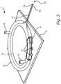
- FIG. 2 illustrates an SSL lighting device 1, the housing 2 of which has the shape of a torus.
- the housing 2 can have another shape, for example the shape of a cube, a rectangular prism or a round container.
- both ends 7a, 7b of the elongated light guide are arranged outside the housing 2, and they are joined to form a joint portion 19 for emitting light.
- the housing 2 has one or several inlets 14 and one or several outlets 15 for a cooling fluid in order to cool the housing 2 interior, the SSL light sources 4 and the portion of the light guide 6 which is arranged inside the housing 2.
- the inlets 14 and outlets 15 are arranged in the housing 2 wall.
- the fluid may be a gas, a mixture of gases, a liquid or a mixture of liquids.
- the fluid may be air.
- the SSL lighting device 2 in figure 2 operates in basically the same way as the SSL lighting device in figure 1 .
- a difference is that the housing 2 and its interior are cooled by convection.
- a fluid typically air
- the housing may be rectangular, there may be more than one elongated light guide, the portions for emitting light may be arranged so that they emit light in different directions and the SSL lighting device may provided with means for both convection cooling and liquid cooling.
Landscapes
- Physics & Mathematics (AREA)
- Engineering & Computer Science (AREA)
- Optics & Photonics (AREA)
- General Engineering & Computer Science (AREA)
- General Physics & Mathematics (AREA)
- Microelectronics & Electronic Packaging (AREA)
- Non-Portable Lighting Devices Or Systems Thereof (AREA)
- Planar Illumination Modules (AREA)
Priority Applications (2)
| Application Number | Priority Date | Filing Date | Title |
|---|---|---|---|
| EP14719325.4A EP2992267B1 (en) | 2013-05-03 | 2014-04-25 | Solid state lighting device |
| PL14719325T PL2992267T3 (pl) | 2013-05-03 | 2014-04-25 | Urządzenie oświetleniowe w stanie stałym |
Applications Claiming Priority (3)
| Application Number | Priority Date | Filing Date | Title |
|---|---|---|---|
| EP13166406 | 2013-05-03 | ||
| PCT/EP2014/058413 WO2014177457A1 (en) | 2013-05-03 | 2014-04-25 | Solid state lighting device |
| EP14719325.4A EP2992267B1 (en) | 2013-05-03 | 2014-04-25 | Solid state lighting device |
Publications (2)
| Publication Number | Publication Date |
|---|---|
| EP2992267A1 EP2992267A1 (en) | 2016-03-09 |
| EP2992267B1 true EP2992267B1 (en) | 2017-06-14 |
Family
ID=48463703
Family Applications (1)
| Application Number | Title | Priority Date | Filing Date |
|---|---|---|---|
| EP14719325.4A Active EP2992267B1 (en) | 2013-05-03 | 2014-04-25 | Solid state lighting device |
Country Status (7)
| Country | Link |
|---|---|
| US (1) | US9874317B2 (pl) |
| EP (1) | EP2992267B1 (pl) |
| JP (1) | JP6058861B2 (pl) |
| CN (1) | CN105190164B (pl) |
| ES (1) | ES2640092T3 (pl) |
| PL (1) | PL2992267T3 (pl) |
| WO (1) | WO2014177457A1 (pl) |
Families Citing this family (11)
| Publication number | Priority date | Publication date | Assignee | Title |
|---|---|---|---|---|
| ES2781873T3 (es) | 2012-08-28 | 2020-09-08 | Delos Living Llc | Sistemas y métodos para mejorar el bienestar asociado con ambientes habitables |
| US20150338336A1 (en) * | 2013-05-23 | 2015-11-26 | Sensor Electronic Technology, Inc. | Reflective Transparent Optical Chamber |
| FR3009063B1 (fr) * | 2013-07-25 | 2018-03-30 | Valeo Systemes Thermiques | Dispositif lumineux |
| CA2940766A1 (en) | 2014-02-28 | 2015-09-03 | Delos Living Llc | Systems, methods and articles for enhancing wellness associated with habitable environments |
| EP3292739B1 (en) * | 2015-05-07 | 2020-02-19 | Signify Holding B.V. | High intensity light source with temperature independent color point |
| US10920939B2 (en) * | 2017-07-07 | 2021-02-16 | Signify Holding B.V. | Light concentrator module |
| WO2019046580A1 (en) | 2017-08-30 | 2019-03-07 | Delos Living Llc | SYSTEMS, METHODS AND ARTICLES FOR EVALUATING AND / OR IMPROVING HEALTH AND WELL-BEING |
| CN110886977B (zh) * | 2018-09-10 | 2021-07-27 | 深圳市绎立锐光科技开发有限公司 | 发光装置 |
| US11649977B2 (en) | 2018-09-14 | 2023-05-16 | Delos Living Llc | Systems and methods for air remediation |
| US11844163B2 (en) | 2019-02-26 | 2023-12-12 | Delos Living Llc | Method and apparatus for lighting in an office environment |
| US11898898B2 (en) | 2019-03-25 | 2024-02-13 | Delos Living Llc | Systems and methods for acoustic monitoring |
Family Cites Families (13)
| Publication number | Priority date | Publication date | Assignee | Title |
|---|---|---|---|---|
| US5109463A (en) * | 1990-06-25 | 1992-04-28 | Lee Ho Shang | Fiber optic lamp |
| DE19853106A1 (de) | 1998-11-18 | 2000-05-31 | Bayer Ag | Fluoreszierende, strukturierte Formkörper |
| US6542231B1 (en) * | 2000-08-22 | 2003-04-01 | Thermo Finnegan Llc | Fiber-coupled liquid sample analyzer with liquid flow cell |
| JP2003150084A (ja) | 2001-11-09 | 2003-05-21 | Hideo Murakami | 光ファイバーロッド発光表示体 |
| DK4008949T3 (da) | 2004-09-29 | 2024-03-04 | Signify Holding Bv | Belysningsindretning |
| GB2461689A (en) | 2008-07-07 | 2010-01-13 | Sharp Kk | Illumination panel for display back light |
| JP5777108B2 (ja) | 2008-07-25 | 2015-09-09 | コーニング インコーポレイテッド | 生物学的用途のためのナノ構造光ファイバ照明系および方法 |
| US8242462B2 (en) * | 2009-01-23 | 2012-08-14 | Lumencor, Inc. | Lighting design of high quality biomedical devices |
| JP4659155B2 (ja) | 2009-02-14 | 2011-03-30 | 株式会社栗原工業 | 目視検査用ライト |
| DE202010001155U1 (de) | 2010-01-20 | 2010-04-22 | Zumtobel Lighting Gmbh | Lichtleiterplatte mit phosphorhaltigen Strukturelementen |
| TW201137469A (en) | 2010-04-30 | 2011-11-01 | Aqua Tech Optical Corp | Light guiding module and manufacturing method thereof |
| US8807799B2 (en) * | 2010-06-11 | 2014-08-19 | Intematix Corporation | LED-based lamps |
| ES2787826T3 (es) | 2011-04-28 | 2020-10-19 | L E S S Ltd | Aparatos de guía de ondas para sistemas de iluminación |
-
2014
- 2014-04-25 WO PCT/EP2014/058413 patent/WO2014177457A1/en not_active Ceased
- 2014-04-25 ES ES14719325.4T patent/ES2640092T3/es active Active
- 2014-04-25 US US14/888,820 patent/US9874317B2/en active Active
- 2014-04-25 JP JP2016509478A patent/JP6058861B2/ja active Active
- 2014-04-25 CN CN201480024972.2A patent/CN105190164B/zh active Active
- 2014-04-25 PL PL14719325T patent/PL2992267T3/pl unknown
- 2014-04-25 EP EP14719325.4A patent/EP2992267B1/en active Active
Also Published As
| Publication number | Publication date |
|---|---|
| CN105190164B (zh) | 2019-01-04 |
| EP2992267A1 (en) | 2016-03-09 |
| JP2016517154A (ja) | 2016-06-09 |
| US20160076711A1 (en) | 2016-03-17 |
| WO2014177457A1 (en) | 2014-11-06 |
| PL2992267T3 (pl) | 2017-11-30 |
| ES2640092T3 (es) | 2017-10-31 |
| JP6058861B2 (ja) | 2017-01-11 |
| US9874317B2 (en) | 2018-01-23 |
| CN105190164A (zh) | 2015-12-23 |
Similar Documents
| Publication | Publication Date | Title |
|---|---|---|
| EP2992267B1 (en) | Solid state lighting device | |
| EP3047527B1 (en) | A light emitting device | |
| US8629982B2 (en) | Light emitting diode illumination system | |
| US20200041885A1 (en) | Light concentrator module | |
| EP2998790A1 (en) | Multi-staged lighting device | |
| CN110945285B (zh) | 照明设备和照明系统 | |
| CN115917212A (zh) | 具有高cri的高强度光源 | |
| CN111148940B (zh) | 具有cpc、光导和附加磷光体的发光聚光器 | |
| US11604321B2 (en) | Light generating system comprising an elongated luminescent body | |
| CN114402161A (zh) | 具有高cri的高强度光源 | |
| US12209746B2 (en) | Laser source tunable white light module | |
| CN114761862A (zh) | 具有微棱镜反射器的紧凑型激光束组合器 | |
| WO2021069562A1 (en) | White luminescent concentrator with ld coupling as additional channel | |
| EP4476477B1 (en) | Heatsink comprising a closed-loop slit for pumping a cylindrical phosphor body | |
| WO2023247568A1 (en) | Laser source lightguide spider module | |
| CN117597545A (zh) | 集成固态光源和磷光体模块 | |
| CN117480343A (zh) | 使用锥形光纤改善热管理的基于激光器的光引擎 |
Legal Events
| Date | Code | Title | Description |
|---|---|---|---|
| PUAI | Public reference made under article 153(3) epc to a published international application that has entered the european phase |
Free format text: ORIGINAL CODE: 0009012 |
|
| 17P | Request for examination filed |
Effective date: 20151203 |
|
| AK | Designated contracting states |
Kind code of ref document: A1 Designated state(s): AL AT BE BG CH CY CZ DE DK EE ES FI FR GB GR HR HU IE IS IT LI LT LU LV MC MK MT NL NO PL PT RO RS SE SI SK SM TR |
|
| AX | Request for extension of the european patent |
Extension state: BA ME |
|
| DAX | Request for extension of the european patent (deleted) | ||
| RAP1 | Party data changed (applicant data changed or rights of an application transferred) |
Owner name: PHILIPS LIGHTING HOLDING B.V. |
|
| REG | Reference to a national code |
Ref country code: DE Ref legal event code: R079 Ref document number: 602014010765 Country of ref document: DE Free format text: PREVIOUS MAIN CLASS: F21V0008000000 Ipc: F21V0029000000 |
|
| RIC1 | Information provided on ipc code assigned before grant |
Ipc: F21V 29/00 20150101AFI20161019BHEP Ipc: F21K 9/64 20160101ALI20161019BHEP Ipc: F21V 29/56 20150101ALI20161019BHEP Ipc: F21Y 103/10 20160101ALI20161019BHEP Ipc: F21Y 115/10 20160101ALI20161019BHEP Ipc: F21Y 103/33 20160101ALI20161019BHEP Ipc: F21Y 101/00 20160101ALI20161019BHEP Ipc: F21V 29/83 20150101ALI20161019BHEP Ipc: F21V 8/00 20060101ALI20161019BHEP Ipc: F21V 13/08 20060101ALI20161019BHEP Ipc: F21K 9/61 20160101ALI20161019BHEP Ipc: F21V 29/70 20150101ALI20161019BHEP |
|
| GRAP | Despatch of communication of intention to grant a patent |
Free format text: ORIGINAL CODE: EPIDOSNIGR1 |
|
| INTG | Intention to grant announced |
Effective date: 20161202 |
|
| GRAS | Grant fee paid |
Free format text: ORIGINAL CODE: EPIDOSNIGR3 |
|
| GRAA | (expected) grant |
Free format text: ORIGINAL CODE: 0009210 |
|
| AK | Designated contracting states |
Kind code of ref document: B1 Designated state(s): AL AT BE BG CH CY CZ DE DK EE ES FI FR GB GR HR HU IE IS IT LI LT LU LV MC MK MT NL NO PL PT RO RS SE SI SK SM TR |
|
| REG | Reference to a national code |
Ref country code: GB Ref legal event code: FG4D |
|
| REG | Reference to a national code |
Ref country code: CH Ref legal event code: EP Ref country code: AT Ref legal event code: REF Ref document number: 901344 Country of ref document: AT Kind code of ref document: T Effective date: 20170615 |
|
| REG | Reference to a national code |
Ref country code: IE Ref legal event code: FG4D |
|
| REG | Reference to a national code |
Ref country code: DE Ref legal event code: R096 Ref document number: 602014010765 Country of ref document: DE |
|
| RIN2 | Information on inventor provided after grant (corrected) |
Inventor name: VAN DER TEMPEL, LEENDERT Inventor name: HIKMET, RIFAT ATA MUSTAFA Inventor name: VAN BOMMEL, TIES Inventor name: DIJKEN, DURANDUS KORNELIUS |
|
| REG | Reference to a national code |
Ref country code: NL Ref legal event code: MP Effective date: 20170614 |
|
| REG | Reference to a national code |
Ref country code: LT Ref legal event code: MG4D |
|
| PG25 | Lapsed in a contracting state [announced via postgrant information from national office to epo] |
Ref country code: HR Free format text: LAPSE BECAUSE OF FAILURE TO SUBMIT A TRANSLATION OF THE DESCRIPTION OR TO PAY THE FEE WITHIN THE PRESCRIBED TIME-LIMIT Effective date: 20170614 Ref country code: NO Free format text: LAPSE BECAUSE OF FAILURE TO SUBMIT A TRANSLATION OF THE DESCRIPTION OR TO PAY THE FEE WITHIN THE PRESCRIBED TIME-LIMIT Effective date: 20170914 Ref country code: LT Free format text: LAPSE BECAUSE OF FAILURE TO SUBMIT A TRANSLATION OF THE DESCRIPTION OR TO PAY THE FEE WITHIN THE PRESCRIBED TIME-LIMIT Effective date: 20170614 Ref country code: FI Free format text: LAPSE BECAUSE OF FAILURE TO SUBMIT A TRANSLATION OF THE DESCRIPTION OR TO PAY THE FEE WITHIN THE PRESCRIBED TIME-LIMIT Effective date: 20170614 Ref country code: GR Free format text: LAPSE BECAUSE OF FAILURE TO SUBMIT A TRANSLATION OF THE DESCRIPTION OR TO PAY THE FEE WITHIN THE PRESCRIBED TIME-LIMIT Effective date: 20170915 |
|
| REG | Reference to a national code |
Ref country code: ES Ref legal event code: FG2A Ref document number: 2640092 Country of ref document: ES Kind code of ref document: T3 Effective date: 20171031 |
|
| REG | Reference to a national code |
Ref country code: AT Ref legal event code: MK05 Ref document number: 901344 Country of ref document: AT Kind code of ref document: T Effective date: 20170614 |
|
| PG25 | Lapsed in a contracting state [announced via postgrant information from national office to epo] |
Ref country code: SE Free format text: LAPSE BECAUSE OF FAILURE TO SUBMIT A TRANSLATION OF THE DESCRIPTION OR TO PAY THE FEE WITHIN THE PRESCRIBED TIME-LIMIT Effective date: 20170614 Ref country code: RS Free format text: LAPSE BECAUSE OF FAILURE TO SUBMIT A TRANSLATION OF THE DESCRIPTION OR TO PAY THE FEE WITHIN THE PRESCRIBED TIME-LIMIT Effective date: 20170614 Ref country code: LV Free format text: LAPSE BECAUSE OF FAILURE TO SUBMIT A TRANSLATION OF THE DESCRIPTION OR TO PAY THE FEE WITHIN THE PRESCRIBED TIME-LIMIT Effective date: 20170614 Ref country code: BG Free format text: LAPSE BECAUSE OF FAILURE TO SUBMIT A TRANSLATION OF THE DESCRIPTION OR TO PAY THE FEE WITHIN THE PRESCRIBED TIME-LIMIT Effective date: 20170914 Ref country code: NL Free format text: LAPSE BECAUSE OF FAILURE TO SUBMIT A TRANSLATION OF THE DESCRIPTION OR TO PAY THE FEE WITHIN THE PRESCRIBED TIME-LIMIT Effective date: 20170614 |
|
| PG25 | Lapsed in a contracting state [announced via postgrant information from national office to epo] |
Ref country code: RO Free format text: LAPSE BECAUSE OF FAILURE TO SUBMIT A TRANSLATION OF THE DESCRIPTION OR TO PAY THE FEE WITHIN THE PRESCRIBED TIME-LIMIT Effective date: 20170614 Ref country code: CZ Free format text: LAPSE BECAUSE OF FAILURE TO SUBMIT A TRANSLATION OF THE DESCRIPTION OR TO PAY THE FEE WITHIN THE PRESCRIBED TIME-LIMIT Effective date: 20170614 Ref country code: EE Free format text: LAPSE BECAUSE OF FAILURE TO SUBMIT A TRANSLATION OF THE DESCRIPTION OR TO PAY THE FEE WITHIN THE PRESCRIBED TIME-LIMIT Effective date: 20170614 Ref country code: SK Free format text: LAPSE BECAUSE OF FAILURE TO SUBMIT A TRANSLATION OF THE DESCRIPTION OR TO PAY THE FEE WITHIN THE PRESCRIBED TIME-LIMIT Effective date: 20170614 Ref country code: AT Free format text: LAPSE BECAUSE OF FAILURE TO SUBMIT A TRANSLATION OF THE DESCRIPTION OR TO PAY THE FEE WITHIN THE PRESCRIBED TIME-LIMIT Effective date: 20170614 |
|
| PG25 | Lapsed in a contracting state [announced via postgrant information from national office to epo] |
Ref country code: IS Free format text: LAPSE BECAUSE OF FAILURE TO SUBMIT A TRANSLATION OF THE DESCRIPTION OR TO PAY THE FEE WITHIN THE PRESCRIBED TIME-LIMIT Effective date: 20171014 Ref country code: SM Free format text: LAPSE BECAUSE OF FAILURE TO SUBMIT A TRANSLATION OF THE DESCRIPTION OR TO PAY THE FEE WITHIN THE PRESCRIBED TIME-LIMIT Effective date: 20170614 |
|
| REG | Reference to a national code |
Ref country code: DE Ref legal event code: R097 Ref document number: 602014010765 Country of ref document: DE |
|
| PLBE | No opposition filed within time limit |
Free format text: ORIGINAL CODE: 0009261 |
|
| STAA | Information on the status of an ep patent application or granted ep patent |
Free format text: STATUS: NO OPPOSITION FILED WITHIN TIME LIMIT |
|
| REG | Reference to a national code |
Ref country code: FR Ref legal event code: PLFP Year of fee payment: 5 |
|
| PG25 | Lapsed in a contracting state [announced via postgrant information from national office to epo] |
Ref country code: DK Free format text: LAPSE BECAUSE OF FAILURE TO SUBMIT A TRANSLATION OF THE DESCRIPTION OR TO PAY THE FEE WITHIN THE PRESCRIBED TIME-LIMIT Effective date: 20170614 |
|
| 26N | No opposition filed |
Effective date: 20180315 |
|
| PG25 | Lapsed in a contracting state [announced via postgrant information from national office to epo] |
Ref country code: SI Free format text: LAPSE BECAUSE OF FAILURE TO SUBMIT A TRANSLATION OF THE DESCRIPTION OR TO PAY THE FEE WITHIN THE PRESCRIBED TIME-LIMIT Effective date: 20170614 |
|
| PG25 | Lapsed in a contracting state [announced via postgrant information from national office to epo] |
Ref country code: MC Free format text: LAPSE BECAUSE OF FAILURE TO SUBMIT A TRANSLATION OF THE DESCRIPTION OR TO PAY THE FEE WITHIN THE PRESCRIBED TIME-LIMIT Effective date: 20170614 |
|
| REG | Reference to a national code |
Ref country code: CH Ref legal event code: PL |
|
| REG | Reference to a national code |
Ref country code: BE Ref legal event code: MM Effective date: 20180430 |
|
| REG | Reference to a national code |
Ref country code: IE Ref legal event code: MM4A |
|
| PG25 | Lapsed in a contracting state [announced via postgrant information from national office to epo] |
Ref country code: LU Free format text: LAPSE BECAUSE OF NON-PAYMENT OF DUE FEES Effective date: 20180425 |
|
| PG25 | Lapsed in a contracting state [announced via postgrant information from national office to epo] |
Ref country code: BE Free format text: LAPSE BECAUSE OF NON-PAYMENT OF DUE FEES Effective date: 20180430 Ref country code: CH Free format text: LAPSE BECAUSE OF NON-PAYMENT OF DUE FEES Effective date: 20180430 Ref country code: LI Free format text: LAPSE BECAUSE OF NON-PAYMENT OF DUE FEES Effective date: 20180430 |
|
| PG25 | Lapsed in a contracting state [announced via postgrant information from national office to epo] |
Ref country code: IE Free format text: LAPSE BECAUSE OF NON-PAYMENT OF DUE FEES Effective date: 20180425 |
|
| PG25 | Lapsed in a contracting state [announced via postgrant information from national office to epo] |
Ref country code: MT Free format text: LAPSE BECAUSE OF NON-PAYMENT OF DUE FEES Effective date: 20180425 |
|
| PG25 | Lapsed in a contracting state [announced via postgrant information from national office to epo] |
Ref country code: TR Free format text: LAPSE BECAUSE OF FAILURE TO SUBMIT A TRANSLATION OF THE DESCRIPTION OR TO PAY THE FEE WITHIN THE PRESCRIBED TIME-LIMIT Effective date: 20170614 |
|
| PG25 | Lapsed in a contracting state [announced via postgrant information from national office to epo] |
Ref country code: PT Free format text: LAPSE BECAUSE OF FAILURE TO SUBMIT A TRANSLATION OF THE DESCRIPTION OR TO PAY THE FEE WITHIN THE PRESCRIBED TIME-LIMIT Effective date: 20170614 |
|
| PG25 | Lapsed in a contracting state [announced via postgrant information from national office to epo] |
Ref country code: HU Free format text: LAPSE BECAUSE OF FAILURE TO SUBMIT A TRANSLATION OF THE DESCRIPTION OR TO PAY THE FEE WITHIN THE PRESCRIBED TIME-LIMIT; INVALID AB INITIO Effective date: 20140425 Ref country code: MK Free format text: LAPSE BECAUSE OF NON-PAYMENT OF DUE FEES Effective date: 20170614 Ref country code: CY Free format text: LAPSE BECAUSE OF FAILURE TO SUBMIT A TRANSLATION OF THE DESCRIPTION OR TO PAY THE FEE WITHIN THE PRESCRIBED TIME-LIMIT Effective date: 20170614 |
|
| PG25 | Lapsed in a contracting state [announced via postgrant information from national office to epo] |
Ref country code: AL Free format text: LAPSE BECAUSE OF FAILURE TO SUBMIT A TRANSLATION OF THE DESCRIPTION OR TO PAY THE FEE WITHIN THE PRESCRIBED TIME-LIMIT Effective date: 20170614 |
|
| REG | Reference to a national code |
Ref country code: ES Ref legal event code: PC2A Owner name: SIGNIFY HOLDING B.V. Effective date: 20201013 |
|
| REG | Reference to a national code |
Ref country code: DE Ref legal event code: R081 Ref document number: 602014010765 Country of ref document: DE Owner name: SIGNIFY HOLDING B.V., NL Free format text: FORMER OWNER: PHILIPS LIGHTING HOLDING B.V., EINDHOVEN, NL |
|
| P01 | Opt-out of the competence of the unified patent court (upc) registered |
Effective date: 20230421 |
|
| PGFP | Annual fee paid to national office [announced via postgrant information from national office to epo] |
Ref country code: PL Payment date: 20250327 Year of fee payment: 12 |
|
| PGFP | Annual fee paid to national office [announced via postgrant information from national office to epo] |
Ref country code: DE Payment date: 20250502 Year of fee payment: 12 |
|
| PGFP | Annual fee paid to national office [announced via postgrant information from national office to epo] |
Ref country code: GB Payment date: 20250429 Year of fee payment: 12 Ref country code: ES Payment date: 20250513 Year of fee payment: 12 |
|
| PGFP | Annual fee paid to national office [announced via postgrant information from national office to epo] |
Ref country code: IT Payment date: 20250429 Year of fee payment: 12 |
|
| PGFP | Annual fee paid to national office [announced via postgrant information from national office to epo] |
Ref country code: FR Payment date: 20250430 Year of fee payment: 12 |