EP2992205B1 - Gewinnung von kinetischer energie mit cyber-physikalischen systemen - Google Patents
Gewinnung von kinetischer energie mit cyber-physikalischen systemen Download PDFInfo
- Publication number
- EP2992205B1 EP2992205B1 EP14740686.2A EP14740686A EP2992205B1 EP 2992205 B1 EP2992205 B1 EP 2992205B1 EP 14740686 A EP14740686 A EP 14740686A EP 2992205 B1 EP2992205 B1 EP 2992205B1
- Authority
- EP
- European Patent Office
- Prior art keywords
- foil
- optimization
- foil member
- flow
- fluid flow
- Prior art date
- Legal status (The legal status is an assumption and is not a legal conclusion. Google has not performed a legal analysis and makes no representation as to the accuracy of the status listed.)
- Active
Links
- 238000003306 harvesting Methods 0.000 title description 10
- 239000011888 foil Substances 0.000 claims description 124
- 238000005457 optimization Methods 0.000 claims description 87
- 239000012530 fluid Substances 0.000 claims description 70
- 238000006243 chemical reaction Methods 0.000 claims description 23
- 230000000694 effects Effects 0.000 claims description 13
- XLYOFNOQVPJJNP-UHFFFAOYSA-N water Substances O XLYOFNOQVPJJNP-UHFFFAOYSA-N 0.000 claims description 13
- 238000012544 monitoring process Methods 0.000 claims description 10
- 230000010355 oscillation Effects 0.000 claims description 10
- 238000006073 displacement reaction Methods 0.000 claims description 9
- 238000000605 extraction Methods 0.000 claims description 7
- 239000013049 sediment Substances 0.000 claims description 7
- 238000002156 mixing Methods 0.000 claims description 6
- 230000008021 deposition Effects 0.000 claims description 3
- 238000000034 method Methods 0.000 description 28
- 238000013461 design Methods 0.000 description 15
- 238000002474 experimental method Methods 0.000 description 14
- 230000007246 mechanism Effects 0.000 description 14
- 230000006870 function Effects 0.000 description 13
- 230000001970 hydrokinetic effect Effects 0.000 description 11
- 230000006399 behavior Effects 0.000 description 10
- 230000008901 benefit Effects 0.000 description 9
- 230000005611 electricity Effects 0.000 description 9
- 230000004044 response Effects 0.000 description 9
- 238000005259 measurement Methods 0.000 description 8
- 230000003278 mimic effect Effects 0.000 description 8
- 230000003534 oscillatory effect Effects 0.000 description 8
- 230000001052 transient effect Effects 0.000 description 8
- 238000013016 damping Methods 0.000 description 7
- 238000003860 storage Methods 0.000 description 7
- 238000005516 engineering process Methods 0.000 description 6
- 230000007613 environmental effect Effects 0.000 description 6
- 230000008859 change Effects 0.000 description 5
- 238000009434 installation Methods 0.000 description 5
- 239000000284 extract Substances 0.000 description 4
- 238000002922 simulated annealing Methods 0.000 description 4
- 238000004590 computer program Methods 0.000 description 3
- 238000012986 modification Methods 0.000 description 3
- 230000004048 modification Effects 0.000 description 3
- 235000015097 nutrients Nutrition 0.000 description 3
- 230000003287 optical effect Effects 0.000 description 3
- 230000002441 reversible effect Effects 0.000 description 3
- 230000003068 static effect Effects 0.000 description 3
- 238000012360 testing method Methods 0.000 description 3
- 230000001133 acceleration Effects 0.000 description 2
- 230000009471 action Effects 0.000 description 2
- 230000008878 coupling Effects 0.000 description 2
- 239000007789 gas Substances 0.000 description 2
- 230000001976 improved effect Effects 0.000 description 2
- 230000006872 improvement Effects 0.000 description 2
- 238000004519 manufacturing process Methods 0.000 description 2
- 239000000463 material Substances 0.000 description 2
- 239000013307 optical fiber Substances 0.000 description 2
- 238000000917 particle-image velocimetry Methods 0.000 description 2
- 230000000704 physical effect Effects 0.000 description 2
- 238000000053 physical method Methods 0.000 description 2
- 230000000644 propagated effect Effects 0.000 description 2
- 230000036962 time dependent Effects 0.000 description 2
- 235000014653 Carica parviflora Nutrition 0.000 description 1
- 241000283153 Cetacea Species 0.000 description 1
- 241000243321 Cnidaria Species 0.000 description 1
- 230000003044 adaptive effect Effects 0.000 description 1
- 238000013459 approach Methods 0.000 description 1
- 230000003416 augmentation Effects 0.000 description 1
- 230000003190 augmentative effect Effects 0.000 description 1
- 230000002457 bidirectional effect Effects 0.000 description 1
- 230000015572 biosynthetic process Effects 0.000 description 1
- 238000004891 communication Methods 0.000 description 1
- 238000010168 coupling process Methods 0.000 description 1
- 238000005859 coupling reaction Methods 0.000 description 1
- 230000001186 cumulative effect Effects 0.000 description 1
- 230000007423 decrease Effects 0.000 description 1
- 230000001419 dependent effect Effects 0.000 description 1
- 238000011161 development Methods 0.000 description 1
- 238000011156 evaluation Methods 0.000 description 1
- 230000004907 flux Effects 0.000 description 1
- 238000005755 formation reaction Methods 0.000 description 1
- 230000005484 gravity Effects 0.000 description 1
- 230000010354 integration Effects 0.000 description 1
- 230000003993 interaction Effects 0.000 description 1
- 238000012804 iterative process Methods 0.000 description 1
- 239000007788 liquid Substances 0.000 description 1
- 230000007774 longterm Effects 0.000 description 1
- 230000001617 migratory effect Effects 0.000 description 1
- 230000000116 mitigating effect Effects 0.000 description 1
- 230000035515 penetration Effects 0.000 description 1
- 230000000737 periodic effect Effects 0.000 description 1
- 238000011020 pilot scale process Methods 0.000 description 1
- 244000062645 predators Species 0.000 description 1
- 230000008569 process Effects 0.000 description 1
- 230000008707 rearrangement Effects 0.000 description 1
- 230000000630 rising effect Effects 0.000 description 1
- 239000000523 sample Substances 0.000 description 1
- 239000004065 semiconductor Substances 0.000 description 1
- 238000000926 separation method Methods 0.000 description 1
- 230000011273 social behavior Effects 0.000 description 1
- 239000007787 solid Substances 0.000 description 1
- 238000009987 spinning Methods 0.000 description 1
- 230000008093 supporting effect Effects 0.000 description 1
- 230000001360 synchronised effect Effects 0.000 description 1
- 230000002123 temporal effect Effects 0.000 description 1
- 238000012800 visualization Methods 0.000 description 1
Images


Classifications
-
- F—MECHANICAL ENGINEERING; LIGHTING; HEATING; WEAPONS; BLASTING
- F03—MACHINES OR ENGINES FOR LIQUIDS; WIND, SPRING, OR WEIGHT MOTORS; PRODUCING MECHANICAL POWER OR A REACTIVE PROPULSIVE THRUST, NOT OTHERWISE PROVIDED FOR
- F03B—MACHINES OR ENGINES FOR LIQUIDS
- F03B15/00—Controlling
-
- F—MECHANICAL ENGINEERING; LIGHTING; HEATING; WEAPONS; BLASTING
- F03—MACHINES OR ENGINES FOR LIQUIDS; WIND, SPRING, OR WEIGHT MOTORS; PRODUCING MECHANICAL POWER OR A REACTIVE PROPULSIVE THRUST, NOT OTHERWISE PROVIDED FOR
- F03B—MACHINES OR ENGINES FOR LIQUIDS
- F03B13/00—Adaptations of machines or engines for special use; Combinations of machines or engines with driving or driven apparatus; Power stations or aggregates
- F03B13/12—Adaptations of machines or engines for special use; Combinations of machines or engines with driving or driven apparatus; Power stations or aggregates characterised by using wave or tide energy
- F03B13/26—Adaptations of machines or engines for special use; Combinations of machines or engines with driving or driven apparatus; Power stations or aggregates characterised by using wave or tide energy using tide energy
- F03B13/264—Adaptations of machines or engines for special use; Combinations of machines or engines with driving or driven apparatus; Power stations or aggregates characterised by using wave or tide energy using tide energy using the horizontal flow of water resulting from tide movement
-
- F—MECHANICAL ENGINEERING; LIGHTING; HEATING; WEAPONS; BLASTING
- F03—MACHINES OR ENGINES FOR LIQUIDS; WIND, SPRING, OR WEIGHT MOTORS; PRODUCING MECHANICAL POWER OR A REACTIVE PROPULSIVE THRUST, NOT OTHERWISE PROVIDED FOR
- F03B—MACHINES OR ENGINES FOR LIQUIDS
- F03B17/00—Other machines or engines
- F03B17/06—Other machines or engines using liquid flow with predominantly kinetic energy conversion, e.g. of swinging-flap type, "run-of-river", "ultra-low head"
-
- F—MECHANICAL ENGINEERING; LIGHTING; HEATING; WEAPONS; BLASTING
- F05—INDEXING SCHEMES RELATING TO ENGINES OR PUMPS IN VARIOUS SUBCLASSES OF CLASSES F01-F04
- F05B—INDEXING SCHEME RELATING TO WIND, SPRING, WEIGHT, INERTIA OR LIKE MOTORS, TO MACHINES OR ENGINES FOR LIQUIDS COVERED BY SUBCLASSES F03B, F03D AND F03G
- F05B2260/00—Function
- F05B2260/70—Adjusting of angle of incidence or attack of rotating blades
-
- Y—GENERAL TAGGING OF NEW TECHNOLOGICAL DEVELOPMENTS; GENERAL TAGGING OF CROSS-SECTIONAL TECHNOLOGIES SPANNING OVER SEVERAL SECTIONS OF THE IPC; TECHNICAL SUBJECTS COVERED BY FORMER USPC CROSS-REFERENCE ART COLLECTIONS [XRACs] AND DIGESTS
- Y02—TECHNOLOGIES OR APPLICATIONS FOR MITIGATION OR ADAPTATION AGAINST CLIMATE CHANGE
- Y02E—REDUCTION OF GREENHOUSE GAS [GHG] EMISSIONS, RELATED TO ENERGY GENERATION, TRANSMISSION OR DISTRIBUTION
- Y02E10/00—Energy generation through renewable energy sources
- Y02E10/20—Hydro energy
-
- Y—GENERAL TAGGING OF NEW TECHNOLOGICAL DEVELOPMENTS; GENERAL TAGGING OF CROSS-SECTIONAL TECHNOLOGIES SPANNING OVER SEVERAL SECTIONS OF THE IPC; TECHNICAL SUBJECTS COVERED BY FORMER USPC CROSS-REFERENCE ART COLLECTIONS [XRACs] AND DIGESTS
- Y02—TECHNOLOGIES OR APPLICATIONS FOR MITIGATION OR ADAPTATION AGAINST CLIMATE CHANGE
- Y02E—REDUCTION OF GREENHOUSE GAS [GHG] EMISSIONS, RELATED TO ENERGY GENERATION, TRANSMISSION OR DISTRIBUTION
- Y02E10/00—Energy generation through renewable energy sources
- Y02E10/30—Energy from the sea, e.g. using wave energy or salinity gradient
Definitions
- the present invention generally relates to a cyber-physical method, apparatus, and system for converting kinetic energy from a fluid flow. More particularly, the present invention provides a system for interacting with or manipulating a fluid flow to attain one or more optimization objectives.
- hydrokinetic energy in the United States is largely located near densely populated areas, and as a result, has yet to be significantly harnessed.
- hydro-kinetic energy is highly predictable and not associated with harmful emissions.
- the density of hydrokinetic energy in regions of reasonably fast flows is high, and unlike wind energy, the turbulent flow fluctuations are expected to be low so dynamic loading and material fatigue is less of a concern for hydrokinetic power.
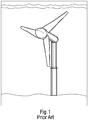
- FIG. 1 for example, an installed turbine is shown.
- the turbines all borrow technology from their close cousins, wind turbines and this technology is relatively mature.
- Most aero- and hydro-dynamic technologies that exist today aircraft wings and blades, propellers, turbines, sails) are designed to operate under steady or quasi-steady conditions, and extreme care is taken to mitigate any unsteadiness in their operation.
- the second and largely unforeseen reason for the unattractiveness of fixed design turbines is that desired characteristics of the turbines may change in the future, not only due to environmental changes but also due to large scale deployment of tidal power farms themselves.
- Turbines extract energy by modifying the flow, thus it is expected that as tidal turbine farms grow, the local flow around each turbine may be completely different.
- a single turbine designed for the undisturbed site may become completely unsuitable as more turbines are installed and the local flow environment changes.
- a turbine design that can adapt to its neighboring turbines and can adjust its operating behavior as the farm grows would provide substantial economic advantages.
- the diameter of a rotary turbine is limited by the depth of water at the site, which is very low at tidal energy hotspots.
- the rotary turbines interfere with each other if they are close to each other, and that means a lot of flow kinetic energy is lost from between the turbines.
- US2010/0143115 discloses a method and apparatus for harvesting the kinetic energy of a moving fluid stream using one or more foils provided with at least two degrees of freedom.
- the apparatus is provided with sensors for monitoring system parameters and a programmable logic controller operable to provide adjustment of control inertial mass and restoring forces for optimizing system performance. Such control is in response to a preprogramed control algorithm.
- US 6323563 discloses a hydrodynamic power-generating system includes a motion-generating subsystem configured to oscillate and pivot under hydrodynamic force to drive a rod.
- the power plant is configured to then convert the oscillating drive motion of the rod to electrical power.
- the motion-generating subsystem includes a pair of spaced beams and a foil is pivotally disposed between the beams.
- a trim flap is pivotally disposed at a downstream edge of the foil.
- the trim flap may be actuated between a first position which causes the foil to pivot in one direction and a second position which causes the foil to pivot in an opposite direction.
- the trim flap is actuated in response to a position sensor operable to determine the position of the beams. The actuation of the flap is predetermined in response to particular beam positions.
- WO2012/040834 discloses a system and method for converting kinetic energy from a fluid flow into mechanical energy.
- the system comprises hydrofoils being able to move linearly in a heaving motion, and being able to oscillate about a spanwise axis in a pitching motion.
- a controller is provided to periodically reset the pitch-heave motion phase.
- the present invention generally relates to a system for converting kinetic energy from a fluid flow. More particularly, the present invention provides a system for interacting with, manipulating, or engaging a fluid flow to attain one or more optimization objectives.
- the system comprising one or more foil members operationally connected to a feedback control loop system.
- the foil member is a hydrofoil member, airfoil member, or combination thereof.
- the foil members configured for one or more degrees of freedom of oscillatory movement within the fluid flow.
- the fluid flow may be a bi-direction fluid flow.
- the two degrees of freedom of the foil members is pitch and plunge.
- the feedback control loop system comprises a sensor system, actuator system, and a controller system.
- the feedback control loop system is configured for optimizing the operation of the foil members to attain one or more optimization objectives.
- the sensor system is configured for directly or indirectly measuring and monitoring the optimization objective during a predetermined time interval.
- the sensor system is configured to determine the energy extracted by monitoring and measuring the foil members degrees of freedom of motion and its conjugate forces.
- the sensor system is connected to the foil members.
- the actuator system is operationally connected to the foil members.
- the actuator system is configured to manipulate the degrees of freedom of motion of the foil members.
- the actuator system is configured to submerge the foil member near or on a bed of a body of water when inactive.
- the controller system is operationally connected to the sensor system to receive the sensor data and the actuator system to manipulate the foil members.
- the controller system is operated by optimization algorithms utilizing the sensor data.
- the controller system is configured for instructing the actuator system to manipulate the foil members to attain one or more optimization objectives.
- the controller system comprises a software for automatically manipulating the foil members to attain the one or more optimization objectives.
- a first optimization objective is optimization of energy extraction from the fluid flow.
- a second optimization objective is the manipulation of a quantifiable effect downstream of the foil member to attain modified turbulence, mixing, or sediment deposition.
- a third optimization objective is to regulate the force on multiple foil members to minimize drag or maximize thrust using minimum energy expenditure. It should be noted that the one or more optimization objectives or the optimization algorithms are configured to be updated or modified.
- one or more support mechanisms may be connected to the actuator system.
- a means for extracting energy from the oscillatory movement of the one or more foil members may be provided.
- a linking means may be provided for allowing the foil members to oscillate within the fluid flow.
- the foil members may be arranged in a cluster whereby the system is configured to or automatically through hydrodynamic interactions and the optimization algorithms synchronize the foil members to mimic operation of a monolithic large scale structure.
- the foil members are situated in the fluid flow and are manipulated to attain one or more optimization objectives.
- a method for interacting with and manipulating a fluid flow.
- the method comprises providing one or more foil members configured for one or more degrees of freedom of oscillatory movement within the fluid flow.
- the foil members operating to oscillate within the fluid flow.
- the operation of the foil members are optimized to attain one or more optimization objectives using a feedback control loop system.
- the foil members are situated in the fluid flow and are manipulated to attain one or more optimization objectives.
- the present invention generally relates to a cyber-physical method, apparatus, and system for converting kinetic energy from a fluid flow. More particularly, the present invention provides a system for interacting with, manipulating, or engaging a fluid flow to attain one or more optimization objectives.
- the fluid flow may be from water currents, such as tidal flow and rivers, wind, or other types of fluid flows.
- the present invention provides the ability to harvest kinetic energy from the fluid flows which have variable strength.
- the kinetic energy may be harvested from a bi-direction fluid flow.
- tidal flow may fluctuate in strength due to rising and falling tides or changing lunar and solar cycles.
- the fluid flow may comprise other types of liquids, other than water, or gases, other than air.
- the cyber-physical system comprising one or more foil members and a feedback control loop system.
- Cyber-physical systems are physical systems whose mechanical response is augmented by an onboard computer in response to real-time measurements, thus enabling enhanced artificial and even unphysical and intelligent behavior.
- the cyber-physical system is customized or modified given the host sites using a foil member but with virtual augmentation using the feedback control loop system. The result is that cyber-physical system of the present invention improves fluid power conversion or other optimization objectives discussed in more detail below.
- the cyber-physical system utilizes recent advances in unsteady hydrodynamics or aerodynamics, such as enhanced lift due to leading edge vortex shedding, a flow regime that traditional turbines are designed to avoid.
- unsteady hydrodynamics or aerodynamics principles kinetic energy extraction can be provided across a large number of dynamically tunable characteristics.
- the foil member is a hydrofoil member, airfoil member, or combination thereof.
- the foil member is a wing or paddle, preferably flexible, but also possibly rigid or semirigid, configured for the efficient extraction of energy from fluid flow.
- the foil members configured for one or more degrees of freedom of oscillatory movement within the fluid flow. In one embodiment, the two degrees of freedom of the foil members is pitch and plunge.
- the foil member is a solid object with a shape such that when placed in a moving fluid at a suitable angle of attack the lift (force generated perpendicular to the fluid flow) is substantially larger than the drag (force generated parallel the fluid flow). If the fluid is a gas, the foil member is called an airfoil member or aerofoil member, and if the fluid is water the foil member is called a hydrofoil.
- the foil member generates lift primarily as a result of its shape and angle of attack.
- the foil member deflects the oncoming fluid, resulting in a force on the foil in the direction opposite to the deflection.
- This force can be resolved into two components: lift and drag.
- This "turning" of the fluid in the vicinity of the foil creates curved streamlines which results in lower pressure on one side and higher pressure on the other.
- This pressure difference is accompanied by a velocity difference, via Bernoulli's principle, so the resulting flowfield about the foil member has a higher average velocity on the upper surface than on the lower surface.
- the feedback control loop system comprising a sensor system, actuator system, and a controller system.
- the feedback control loop system configured for optimizing the operation of the foil members for the local environment and flow conditions in real-time to attain one or more optimization objectives.
- the cyber-physical system uses the feedback control loop system to mimic arbitrary effective physical properties distinct from those inherent to the foil member.
- the system can thus mimic complex, dynamically changing structural behavior (for example time-dependent inertia or negative damping). This allows for modifying the behavior and performance of the hydrofoil in software by modifying the feedback control loop system.
- the cyber-physical hardware can optimize the energy capture and adapt to many different operating conditions.
- the sensor system is configured for directly or indirectly measuring and monitoring the optimization objective during a predetermined time interval.
- the predetermined time interval may preferably be continuously but it also maybe intermittently, periodically, or another definition of the predetermined time interval.
- the sensor system comprises one or more sensors on the foil member and in the surrounding area to measure and monitor flow conditions.
- the sensors may be motion, force, or other types of sensors for monitoring and measuring the foil members.
- the sensor system is configured to determine the energy extracted by monitoring and measuring the foil members degrees of freedom of motion and its conjugate forces. More specifically, the sensors measure the pitch and plunge kinematics, and the force and torque acting on the foil members.
- the sensor system is connected to the foil members.
- the sensor system is integrated, attached, incorporated, or embedded in whole, or in part, within the foil members.
- the sensor system may incorporate the adjoint method.
- the actuator system is operationally connected to the foil members.
- the actuator system includes an electric motor/generator operationally connected to the controller system and an actuator arm connected to the hydrofoil member, and a shaft connected to the motor/generator and the hydrofoil member.
- the actuator arm in one embodiment, is a wing or other shape connected to the hydrofoil member and the motor/generator.
- the wing in one embodiment, may further contain therein a shaft rotatably connected to the hydrofoil member and the electric motor/generator to facilitate production of electricity.
- Motor/generators are capable of running in two opposite modes.
- the shaft usually spins the same way.
- the "change of direction" is in the flow of electricity.
- As a motor it consumes electricity (flows in) to make mechanical power, and as a generator, it consumes mechanical power to produce electricity (flows out).
- Motor action (supplying mechanical power) is in essence the reverse of generator action.
- current is fed by a circuit, through the brushes and slip rings and into the armature.
- This current flowing through the coil wound rotor (armature) turns it into an electromagnet.
- the permanent magnets in the stator repel this electromagnetic force causing the armature to spin.
- the actuator system may include a motor and generate that are separate.
- the actuator system is configured to manipulate the degrees of freedom of motion of the foil members. For example, the actuator system may adjust the pitch angle of the foil member.
- the actuator system is attached or connected to the foil member.
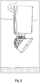
- the actuator system is configured to submerge the foil member near or on a bed of a body of water when inactive.
- the controller system is operationally connected to the sensor system to receive the sensor data and the actuator system to manipulate the foil members.
- the controller system is operated by an optimization algorithm utilizing the sensor data.
- the optimization algorithm is designed to run autonomously, constantly adjusting the cyber-physical actuation for the changing flow conditions to maximize energy capture, with minimal supervisory input.
- the controller system is configured for instructing the actuator system to manipulate the foil members to attain one or more optimization objectives.
- the controller system instructs the actuator system to provide a periodic motion of the foil member to measure and determine the motion of the foil that maximizes the extracted power, potentially sacrificing some energy intermittently to gain even more than was sacrificed in a single stroke of the foil member.
- the controller system or the feedback control loop system may include a computer and software for calculating the alogorithm with input from the sensor data and instructing the actuator system to manipulate the foil member, especially with regard to optimizing the stroke ( Figs. 6-7 ) of the foil member.
- embodiments of the controller may also include one or a multitude of internet based servers, and computer software, including internet web page based code, and methods of application for providing the user with an internet based service. Aspects of the present invention may be embodied as a system, method or computer program product.
- aspects of the present invention may take the form of an entirely hardware embodiment, an entirely software embodiment (including firmware, resident software, micro-code, etc.) or an embodiment combining software and hardware aspects that may all generally be referred to herein as "logic", or "system”.
- aspects of the present invention may take the form of a computer program product embodied in one or more computer readable medium(s) having computer readable program code embodied thereon.
- the motion of the foil member is controlled using actuators by the real-time controller.
- the actuator is reversible, i.e. it is capable of bidirectional conversion between electric energy and mechanical energy.
- the suitable control algorithm With the suitable control algorithm, the net flow of power is out of the system (energy harvesting).
- the control may be open-loop in which the motion is pre-determined, perhaps with some adaptive quality, the true versatility of this methodology is revealed when the feedback loop is closed in which new dynamics and real-time optimization is possible.
- the variety of the hardware hydrofoil member, the degrees of freedom it has, the array of sensors and the control algorithms makes the cyber-physical system easily customizable.
- Linear and angular actuators exert force and torque of the hydrofoil depending on the instantaneous displacement and acceleration.
- This actuation is implemented so as to simulate specific values for the system mass and its supporting spring, i.e. we create a virtual oscillating structure.
- These parameters could be fixed, but could also be time-dependent, nonlinear even negative.
- These parameters are modified in real time depending on the prediction of the tidal currents or on the flow speeds measured in real time.
- a real-time optimization algorithm may be implemented to seek the virtual parameters for maximum power conversion.
- the same physical hardware may be installed in different sites with different flow speed and depth, and the software will adapt itself to the site for maximum power conversion.
- each device will optimize its own operation in collaboration with its neighbors. Synchronized motion of the devices on the scale of the farm can be used to control the global scale flow.
- optimization of more variables describing virtual coupling between the devices can be used to link them and mimic a large-scale device.
- Such a coupled system may be capable of controlling and constraining large-scale flow modifications.
- the transient actuation of the foil member allows it to exploit unsteady fluid dynamic effects such as unsteady leading edge separation, vortex recapture, and dynamic stall to surpass the performance dictated by steady fluid dynamics.
- cyber-physical system adapts itself to the flow environment and conditions in real-time and thereby needs minimal site-dependent design and customization.
- optimization of the cyber-physical system ensures the energy conversion performance, in terms of a power coefficient, is the maximum possible for the site and instantaneous flow conditions.
- the cyber-physical system is less sensitive to modeling uncertainties and perturbations and more tolerant towards widely different and dynamically varying circumstances.
- the controller system comprises a computer and software for automatically manipulating the foil members to attain the one or more optimization objectives.
- a first optimization objective is optimization of energy extraction from the fluid flow.
- a one-time cost of implementing a feedback control loop system using the appropriate sensors can also eliminate the need for a site-specific actuation programming.
- the first optimization objective involves an optimization algorithm which automatically finds the optimal actuation stroke depending upon the current local conditions. For example, an algorithm is used to identify the optimal stroke is to measure the extracted power in real time as a function of the stroke and use a deterministic algorithm like gradient-descent or a stochastic algorithm like simulated annealing to maximize the extracted power. This possibility recovers the recurring manual cost per installation of developing the optimum actuation stroke and makes the device site-agnostic to an extent.
- This method of optimizing the stroke is also far less sensitive to measurement and model uncertainties. For example, when multiple such devices are deployed in vicinity of each other, the modified stroke need not be recomputed but the real-time optimization algorithm automatically accounts for the altered flow and perhaps even synchronizes the strokes for maximum energy conversion, without any manual intervention.
- Our estimate of the available tidal resource is based on the implicit assumption that turbines are the only mechanism for power conversion, because these estimates identify sites appropriate for installation of turbines. In fact, these cyber-physical systems can work with weaker or stronger flow, shallower or deeper sites and thus alter our estimate of the tidal power resource.
- a second optimization objective is the manipulation of a quantifiable effect downstream of the foil member to attain modified turbulence, mixing, or sediment deposition.
- the system of the present invention is ecologically safe, especially to aquatic life, which facilitates more widespread deployment, especially in more populated areas, and requires less environmental mitigation - which further lowers the costs of operation.
- the cyber-physical system may also be used to deploy a tidal power farm.
- Cyber-physical coupling between neighboring devices can be used to give rise to global oscillation patterns in the farm. Synchronization of the devices thus allows the farm to mimic the operation of one large-scale device. This global oscillation pattern can be used to control the large-scale flow modifications. Every tidal farm extracts energy from the flow, and thus slows down the fluid in the wake.
- turbines and oscillating foils also add vorticity and turbulence in its wake, although there is no fundamental fluid mechanical reason for this turbulence.
- the flow speed is reduced and turbulence is minimized.
- the effect of the tidal farm could be to cause the suspended material in the flow to sediment because of the reduced flow speed or to be resuspended because of the turbulence. It appears that there is no fundamental reason why a tradeoff could not be struck by maintaining the same level of nutrient, sediment and gamete mixing by increasing the turbulence the right amount while extracting energy from the flow. If the amount of mixing in the natural habitats is measured, the optimal control algorithm implemented on the scale of the farm can minimize the departure from natural transport. Mathematically, the optimization for maximum power conversion will need to be performed under the additional constraint of maintaining the current levels of mixing while maximizing the energy extracted. The optimization algorithm onboard these devices can be changed to reflect such constraints and thereby alter their performance. Based upon information and belief, this system is the only one that attempts to address the influence of tidal power conversion on the environment.
- a third optimization objective is to regulate the force on multiple foil members to minimize drag or maximize thrust using minimum energy expenditure.
- the one or more optimization objectives or the optimization algorithm are configured to be updated or modified. Moreover, improvements are possible in software by updating the optimization objective or algorithms, and that possibility provides a mechanism for improving performance at minimal costs.
- the cyber-physical system or its software may be adapted to existing prior art systems.
- the support mechanism may be a frame or other structural support attached, connected, or other means known in the art to a sea bed or river bed, land, piles, foundations, or other objects to provide stability and support.
- the support mechanism may also be a frame or other structural support configured to float and stabilized by cables or other fastening means.
- the support mechanism provides a fixed location for the hydrofoil member and feedback control loop system and supports the cyber-physical system in its position of usage. Alternatively, the support mechanism may maintain its fixed location through the effect of gravity on the cyber-physical system acting through the support mechanism.
- a means for extracting kinetic energy from the oscillatory movement of the one or more foil members may be provided.
- the oscillatory movement is converted to electricity using a motor/generator operationally connected to the one or more foil members.
- the kinetic energy may be converted to other types of energy than electricity or may be used in extracting other types of energy.
- a linking means may be provided for allowing the foil members to oscillate within the fluid flow.
- the linking means is a one or more gear mechanisms connected between the hydrofoil members and the actuator system.
- the gear mechanism connects the hydrofoil member to a shaft of the actuator system for connecting to the electric motor/generator for producing electricity.
- the foil members may be arranged in a cluster or farm.
- the optimal control algorithm synchronizes the strokes of the foils to mimic to mimic operation of a monolithic large scale structure, which cooperatively extracts the maximum possible energy from the flow on the global scale.
- the principle of operation of the oscillating foil members is linear motion rather than rotational blade motion.
- the orientation of the hydrofoil member relative to the fluid flow called the hydrofoil pitch, is dynamically adjusted by the feedback control loop system so that oncoming flow pushes the hydrofoil member downwards on a down stroke and upwards on an upward stroke.
- the hydrofoil member pitch is actively controlled using the feedback control loop system with an optimization algorithm, with particular focus on maintaining quasi-steady dynamics over the foil member.
- the appropriate tuning of the oscillating hydrofoil members using the feedback control loop system is central to the cyber-physical energy extraction system of the present invention.
- Oscillating hydrofoils have many advantages over turbines in terms of site adaptability and large-scale deployment.
- turbines also employ a streamlined geometry, the blade rotation means that the efficiency varies from the root to tip due to the change in local fluid velocity.
- all locations on an oscillating hydrofoil move at the same speed and hence achieve uniform optimal efficiency.
- Tip losses in rotary turbines significantly reduce their performance, while a foil member can be expanded by installing another foil member adjoining it, and the tip effects can be consolidated or even captured akin to the mechanism achieved in the V-shaped flight formations of migratory birds. Turbines prohibit close placement due to hydrodynamic interference.
- a long foil member can be broken up into smaller hydrofoils sections attached to less powerful actuator-motor/generator unit to suit other design constraints without any loss in hydrodynamic efficiency.
- the linear nature of the oscillating hydrofoil is also more suitable for installation in the shallow and wide geometries of rivers and estuaries.
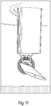
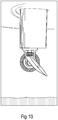
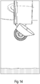
- the turbine geometry permanently blocks the waterway, a hydrofoil can be stopped and stored near the bed so as to give way to passing ships.
- the present invention relies on hydro-elastic instabilities and actuate, not only the pitch of the foil member, but also other degrees of freedom in order to exploit unsteady hydrodynamic effects such as vortex shedding. Coupled with a suitable array of sensors, the foil member transforms in to a cyber-physical system in which we can optimize the response of the system so that it is capable of extracting energy over a wide range of operating conditions while still able to meet other constraints such as tidal farm optimization and environmental impact.
- the foil members are situated or immersed in the fluid flow and are manipulated automatically to attain one or more optimization objectives in real-time operation.
- the foil members may be manipulated automatically manually, or a combination thereof.
- the foil member is tilted downwards on a down stroke and upwards on an up stroke.
- the hydrodynamic force on the foil member points in the direction of the motion, and the flow does mechanical work on the foil member, which may be used to drive a motor / generator of the actuator system.
- the hydrofoil member is operating along a horizontal axis and the actuator arm is oriented along a vertical axis, however, the hydrofoil member may also be alternatively be configured to operate along a vertical axis and the actuator arm may be oriented along a horizontal axis. It should be noted that the kinetic energy of the actuator arm may also be capture by connecting the actuator arm to a motor/generator. Also, it should be noted that the system may be operated in realtime, near realtime, non-realtime, or another time period.
- the foil members are situated or immersed in the fluid flow and are manipulated automatically to attain one or more optimization objectives in real-time operation.
- the hydrofoil member is operating along a horizontal axis and the actuator arm is oriented along a vertical axis, however, the actuator arm and support mechanism is attached to seabed floor.
- a method for interacting with and manipulating a fluid flow using the system above.
- the method comprises providing one or more foil members configured for one or more degrees of freedom of oscillatory movement within the fluid flow.
- the foil members operating to oscillate within the fluid flow.
- the operation of the foil members are optimized to attain one or more optimization objectives using a feedback control loop system.
- the foil members are situated in the fluid flow and are manipulated to attain one or more optimization objectives.
- the cyber-physical system hardware installations can be tuned in real-time by the software to optimize the performance, and thus lead to improved price to performance ratio, economy of scale in manufacturing, cooperative behavior across tidal farms, and upgrades at low unit cost.
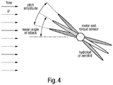
- a system for kinetic energy conversion comprises a rigid wing or foil member was operationally connected to a feedback control loop system having an electric motor/generator or servo motos which controls and manipulates pitch angle. Sensors are embedded within the foil member to measure the angular displacement of the wing and the pitching torque exterted by the fluid on the foil member. The feedback control loop system monitors the displacement and applies a restoring torque proportional to the angular displacement, thus imitating a torsional spring.
- the spring constant of this spring can be tuned in software, and this manner optimized for different flow conditions. Furthermore, by monitoring the torque and incorporating this into the control algorithm, the effective inertia of the foil member can be electronically varied, creating a virtual structure that can be dynamically tuned. A real-time controller monitors the position and forces on the foil member and maintains the system dynamics so that energy harvesting is accomplished at maximum efficiency. Note, the symmetry of the system allows it to operate without any reconfiguration if the fluid stream changes direction.
- the setup consists of a thin symmetric airfoil (or hydrofoil) mounted with two degrees of freedom (pitch and plunge) and actuated using servo motors controlled by a real-time digital controller.
- Different air/hydrofoils will be used, with chord length varying between 2-5cm and span ranging between 30-50cm. This allows for different environments and parameter.
- the control will be implemented using a commercial real-time controller programmed via a MATLAB-SIMULINK interface. Typical flow speeds in the wind tunnel are 1-20 m/s, while the water channel is capable of 0.1-2 m/s.
- This configuration corresponds to a flow Reynolds number ranging from approximately 2000 to 50000, with an estimated power output of 1-5 W in both air and water.
- the typical Reynolds number for the envisaged pilot scale prototype (size ⁇ 1 m ⁇ 20 m in a 2 m/s flow for estimated peak electric power rating of 250 kW) is around 2 ⁇ 10 6 .
- the fluid dynamic time scales and forces are different for the experiments in the two fluids.
- the scale for the fluid force on the foil is given by pU 2 A, while the typical time scale is given by L/U (L being the width of the foil).
- L/U L being the width of the foil
- Hot wire anemometers can be used to measure the local instantaneous velocity (and shed vorticity) with high temporal resolution.
- Particle Image Velocimetry (PIV) will be used to obtain global measurements of the flow field around the hydrofoil. These measurements give detailed information about the unsteady vortex behavior central to the enhanced performance of our system.
- F cp is the cyber-physical force on the foil
- ⁇ is its linear velocity
- ⁇ cp the cyber-physical torque
- ⁇ the angular velocity
- T is the interval over which the motion periodically repeats itself.
- Each component of the integrand will be measured in our experiments and the integration carried in software to determine the net power flux.
- a negative integral denotes power flow from the hydrofoil into the fluid while a positive value indicates energy harvesting.
- the power transient (integrand in (4)) during one oscillation of the hydrofoil is not constant, and in fact it does not even have to be positive.
- the integrand may very well be negative, which reflects temporarily sacrificing some energy to move the hydrofoil for example when the cyber-physical damping has a negative value.
- we can ensure that such temporary sacrifice will always be accompanied by an even greater benefit.
- some of the optimization algorithms we implement work by starting with a cyber-physical state which corresponds to positive value for the integral in (4) and gradually increasing its value by successively changing the cyber-physical state. Algorithms based on strict gradient ascent (i.e.
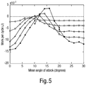
- Fig. 5 illustrates, over a range of parameter there is net flow of energy from the fluid to the motor/generator, indicating energy harvesting.
- the system of Fig. 3 was operated at varying mean angles attack to the oncoming stream, and pitching amplitudes ranging from 2° (blue) to 10° (red) which is plotted on Fig. 5 .
- the oscillation frequency is f - 40Hz corresponding to a non-dimensional value of f L/U - 0.07. Note, that for the moderate range of inclination angles the work per unit cycle is positive (above the dotted line), meaning that the system was harvesting energy from the field.
- Fig. 5 shows that while the quasi-steady prediction is accurate when the foil member is approximately aligned with the flow, energy can indeed be extracted at high average angles of attack, when the quasi-steady approximation fails.
- experiments were performed with oscillating the foil sinusoidally with pitching amplitudes ranging from 2-10° about different mean angles of attack of the foil.
- the quasi-steady theory holds and the work extracted per cycle of oscillations is negative.
- the airfoil stalls and unsteady effects become important. It appears that in a small range of mean angle of attack the motion of the foil is able to extract positive value of energy from the flow.
- the objective is to develop algorithms to be tested in the wind tunnel and the water channel.
- a test was planned for a variety of algorithms with varying complexities.
- Theoretically, the choice of the control process is divided into two parts: the optimization parameters and the optimization algorithm.
- the simplest control parameters are started by mimicking physical properties artificially with the cyber-physical feedback.
- the optimization variables may be interpreted as the linear and nonlinear coefficients of the spring stiffness, damping coefficient, inertia, and form a finite dimensional space to optimize from, but are not necessarily restricted to physically achievable values, as long as on average energy is extracted from the flow and not fed in by the control system.
- the cyber-physical added mass and moment of inertia could be made negative to offset some of the real inertia and thus accelerate the motion of the hydrofoil.
- the cyberphysical variable can vary on the time scale of the oscillations. For example, it may be necessary to make the damping coefficient negative for a small part of the oscillation cycle where the hydrodynamic damping is largest.
- the optimization variables become functions of time and form an infinite-dimensional vector space. Optimization over this infinite-dimensional space requires advanced techniques, but this added complexity also allows fine control over the resulting flow, for example over the pattern of shed vorticity. Note that in essence optimizing the cyber-physical variables is mathematically equivalent to optimizing the transient cyber-physical force and torque, because ultimately it is the forces and torques that control the motion.
- Optimization algorithms are iterative processes, where the user successively improves the objective by trying different value of the optimization variable.
- the algorithms we plan to use both deterministic and stochastic algorithms for optimization. The next iteration depends deterministically on the result of the current iteration in deterministic algorithms, while in stochastic algorithms an element of randomness also plays a role.
- the deterministic algorithms may be further classified into function value based, where only the function value can be used, and gradient based, where the gradient of the objective function with respect to the optimization variables is also used.
- the optimization algorithms are identical to the ones used in numerical optimization, with the exception that the objective function in cyber-physical systems is measured physically.
- the cost of optimization is expressed in terms of the number of objective function evaluations, and this translates into the number of measurements required to find the optimum.
- the three algorithms we plan to use (names of the algorithms reflect the conventional minimization of the objective) are:
- the optimization algorithms will be tested under three flow conditions (i) steady, (ii) gradually changing, and (iii) intermittent. Tests under these conditions are instrumental in verifying the transient response of the cyber-physical system. Experiments in steady flow confirm that the individual components and the integrated system is functioning properly.
- a sudden transient like a passing wave or a vessel can temporarily alter the flow around the device and thus throw it off its optimal stroke. This scenario is quite realistic and it is crucial that the system recovers from such transients.
- the steady and transient scenarios are easily set up by controlling the flow rate through the channel and provide invaluable information regarding the performance of these algorithms.
- Embodiment of the present invention including the controller system and the feedback control loop system may operate on a network for implementing the system of the present invention.
- the system can be employed in conjunction with a computer-based system, where the elements can be implemented in hardware, software, firmware, or combinations thereof.
- Network may include workstations, specialist workstations, and intermediary workstations. Each of the workstations may be configured to communicate with an application server via internet connections.
- the server may include processors and memory for hosting different versions of the software, with respect to the detailed description of the exemplary implementation.
- the computer readable medium may be a computer readable signal medium or a computer readable storage medium.
- a computer readable storage medium may be, for example, but not limited to, an electronic, magnetic, optical, electromagnetic, infrared, or semiconductor system, apparatus, or device, or any suitable combination of the foregoing.
- a computer readable storage medium may be any tangible medium that can contain, or store a program for use by or in connection with an instruction execution system, apparatus, or device.
- a computer readable signal medium may include a propagated data signal with computer readable program code embodied therein, for example, in baseband or as part of a carrier wave. Such a propagated signal may take any of a variety of forms, including, but not limited to, electro-magnetic, optical, or any suitable combination thereof.
- a computer readable signal medium may be any computer readable medium that is not a computer readable storage medium and that can communicate, propagate, or transport a program for use by or in connection with an instruction execution system, apparatus, or device.
- Program code embodied on a computer readable medium may be transmitted using any appropriate medium, including but not limited to wireless, wireline, optical fiber cable, RF, etc., or any suitable combination of the foregoing.
- Computer program code for carrying out operations for aspects of the present invention may be written in any combination of one or more programming languages, including an object oriented programming language such as Java, Smalltalk, C++ or the like and conventional procedural programming languages, such as the "C" programming language or similar programming languages.
- the program code may execute entirely on the user's computer, partly on the user's computer, as a stand-alone software package, partly on the user's computer and partly on a remote computer or entirely on the remote computer or server.
- the remote computer may be connected to the user's computer through any type of network, including a local area network (LAN) or a wide area network (WAN), or the connection may be made to an external computer (for example, through the Internet using an Internet Service Provider).
- LAN local area network
- WAN wide area network
- Internet Service Provider for example, AT&T, MCI, Sprint, EarthLink, MSN, GTE, etc.
Claims (12)
- System zur kinetischen Energieumwandlung, welches mit einem fluiden Strom zusammenwirkt, aufweisend: ein Flügelbauteil mit zwei Freiheitgraden zum Neigen und Eintauchen innerhalb des Fluidstromes; einer Welle, welche mit dem Flügelbauteil gekoppelt ist, wobei die Welle betreibbar ist entlang einer Schwingungsachse zu schwingen, die senkrecht zur Neigungsachse des Flügels und der Fluidstromrichtung ist,
ein Rückkopplungs-Regelkreissystem, wobei das Rückkopplungs-Regelkreissystem aufweist: ein Sensorsystem mit Sensoren, die in das Flügelbauteil eingebettet sind, um eine Winkelverschiebung und ein Neigungsmoment, die von dem Fluid auf das Flügelbauteil ausgeübt werden, zu messen;
ein Aktuator-System, welches betreibbar mit dem Flügelbauteil gekoppelt ist und einen elektrischen Motor/Generator oder Servomotoren aufweist, welche den Neigungswinkel steuern und manipulieren;
ein Steuersystem, welches betriebsmäßig mit dem Sensorsystem verbunden ist, um die Sensordaten zu empfangen und um das Aktuator-System zu veranlassen, das Flügelbauteil einstellbar um die Neigungsachse zu neigen, so dass der bidirektionale Fluidstrom, der das Flügelbauteil kontaktiert, die Welle veranlasst, entlang der Schwingungsachse zu schwingen;
wobei das Rückkopplungs-Regelkreissystem eine Winkelverschiebung überwacht und ein Rückstellmoment, das proportional zur Winkelverschiebung ist, anlegt, eine Drehfeder imitierend. - System nach Anspruch 1,
wobei das Flügelbauteil ein Wasserflügelbauteil ist. - System nach Anspruch 1,
wobei das Flügelbauteil ein Luftflügelbauteil ist. - System nach einem der vorangehenden Ansprüche,
wobei das Aktuator-System konfiguriert ist, die Grade der Bewegungsfreiheit des Flügelbauteils zu manipulieren. - System nach Anspruch 4,
wobei das Aktuator-System konfiguriert ist, das Flügelbauteil in der Nähe oder auf einem Bett aus einem Wasserkörper zu tauchen, wenn es inaktiv ist. - System nach einem dem der vorhergehenden Ansprüche,
wobei das Steuersystem durch einen Optimierungsalgorithmus unter Verwendung der Sensordaten betrieben wird. - System nach Anspruch 6,
wobei das Steuersystem konfiguriert ist, das Aktuator-System zu instruieren die Flügelbauteile zu manipulieren, um ein Optimierungsziel zu erreichen. - System nach Anspruch 7,
wobei das Steuersystem eine Software zum automatischen Bestimmen der Manipulation der Flügelbauteile aufweist zum Erreichen des Optimierungsziels. - System nach Anspruch 7 oder 8,
wobei das Steuersystem konfiguriert ist zum Überwachen des Optimierungsziels während eines vorbestimmten Zeitintervalls. - System nach einem der Ansprüche 7 bis 9,
wobei das Optimierungsziel das Optimieren der Energiegewinnung aus dem Fluidstrom ist. - System nach einem der Ansprüche 7 bis 9,
wobei das Optimierungsziel das Manipulieren eines quantifizierbaren Effektes stromabwärts des Flügelbauteils ist, um modifizierte Turbulenzen, Mischen oder Sedimentablagerungen zu erreichen. - System nach einem der Ansprüche 7 bis 9,
wobei das Optimierungsziel ist, die Kraft auf mehrere Flügelbauteile zu regulieren, um den Widerstand zu minimieren oder den Schub mit minimalem Energieaufwand zu maximieren.
Applications Claiming Priority (2)
| Application Number | Priority Date | Filing Date | Title |
|---|---|---|---|
| US201361754757P | 2013-01-21 | 2013-01-21 | |
| PCT/US2014/012376 WO2014113809A1 (en) | 2013-01-21 | 2014-01-21 | Kinetic energy harvesting using cyber-physical systems |
Publications (3)
| Publication Number | Publication Date |
|---|---|
| EP2992205A1 EP2992205A1 (de) | 2016-03-09 |
| EP2992205A4 EP2992205A4 (de) | 2017-04-05 |
| EP2992205B1 true EP2992205B1 (de) | 2019-12-11 |
Family
ID=51207144
Family Applications (1)
| Application Number | Title | Priority Date | Filing Date |
|---|---|---|---|
| EP14740686.2A Active EP2992205B1 (de) | 2013-01-21 | 2014-01-21 | Gewinnung von kinetischer energie mit cyber-physikalischen systemen |
Country Status (4)
| Country | Link |
|---|---|
| US (1) | US10087910B2 (de) |
| EP (1) | EP2992205B1 (de) |
| BR (1) | BR112015017314A2 (de) |
| WO (1) | WO2014113809A1 (de) |
Families Citing this family (2)
| Publication number | Priority date | Publication date | Assignee | Title |
|---|---|---|---|---|
| US11591084B2 (en) * | 2017-01-03 | 2023-02-28 | The Texas A&M University System | Cycloidal rotor micro-air vehicle |
| EP4109736A1 (de) * | 2021-06-23 | 2022-12-28 | Wobben Properties GmbH | Verfahren zum betrieb einer windturbine mit optimierten parametern |
Family Cites Families (43)
| Publication number | Priority date | Publication date | Assignee | Title |
|---|---|---|---|---|
| US4247251A (en) * | 1978-05-17 | 1981-01-27 | Wuenscher Hans F | Cycloidal fluid flow engine |
| US5008863A (en) * | 1979-06-04 | 1991-04-16 | The United States Of America As Represented By The Secretary Of The Navy | Low noise sonar support system |
| US4255085A (en) * | 1980-06-02 | 1981-03-10 | Evans Frederick C | Flow augmenters for vertical-axis windmills and turbines |
| US4430044A (en) * | 1981-11-23 | 1984-02-07 | Liljegren L Kenyon | Vertical axis wind turbine |
| EP0927304B1 (de) * | 1996-09-20 | 2004-05-12 | Lee Arnold | Energiegewinnung aus strömenden fluiden |
| US6884020B2 (en) * | 1999-01-06 | 2005-04-26 | Water Power Industries As | Turbine driven with a fluid medium |
| US6323563B1 (en) * | 1999-07-25 | 2001-11-27 | Robert C. Kallenberg, Jr. | Hydrodynamic power-generating system |
| GB0128590D0 (en) | 2001-11-29 | 2002-01-23 | Engineering Business Ltd | Electricity generators |
| US6877692B2 (en) * | 2003-03-05 | 2005-04-12 | National Research Council Of Canada | Oscillating foil propulsion system |
| GB2412143A (en) | 2004-03-16 | 2005-09-21 | Tidal Energy Business Ltd | Apparatus for extracting or generating power |
| GB2413785A (en) | 2004-05-07 | 2005-11-09 | Marc Paish | Fluid power generation/propulsion system incorporating movable vanes |
| US8100078B2 (en) * | 2004-06-16 | 2012-01-24 | Westerngeco L.L.C. | Steerable hydrofoil |
| US7493759B2 (en) * | 2004-11-15 | 2009-02-24 | The Regents Of The University Of Michigan | Fluid motion energy converter |
| US20090114001A1 (en) | 2007-05-25 | 2009-05-07 | Bernitsas Michael M | Enhancement of vortex induced forces and motion through surface roughness control |
| WO2006093790A2 (en) | 2005-02-25 | 2006-09-08 | Morris, David, C. | Wind fin: articulated, oscillating wind power generator |
| US8469663B2 (en) | 2005-06-01 | 2013-06-25 | Reshydro Llc | Transfer of kinetic energy to and from fluids |
| GB2426794B (en) | 2005-06-03 | 2010-06-02 | Pulse Generation Ltd | An apparatus for oscillating a vane |
| US7762776B2 (en) * | 2006-03-14 | 2010-07-27 | Siegel Aerodynamics, Inc. | Vortex shedding cyclical propeller |
| US7686583B2 (en) | 2006-07-10 | 2010-03-30 | Siegel Aerodynamics, Inc. | Cyclical wave energy converter |
| US20080048455A1 (en) | 2006-08-25 | 2008-02-28 | Matthew Eli Carney | Energy capture in flowing fluids |
| US7791214B2 (en) * | 2006-10-10 | 2010-09-07 | Adaptide, Inc. | Adaptive tidal current power extraction device |
| GB0621628D0 (en) | 2006-10-31 | 2006-12-06 | Pulse Generation Marine Ltd | A directional fluid propulsion system using oscillating hydrofoils |
| US7573143B2 (en) | 2006-12-01 | 2009-08-11 | Humdinger Wind Energy, Llc | Generator utilizing fluid-induced oscillations |
| EP1970302B1 (de) * | 2007-03-13 | 2012-11-21 | Paul Grima | Antriebs- und Lenksystem mit schwingenden Tragflächen |
| GB2463176B (en) * | 2007-05-05 | 2013-03-13 | Gordon David Sherrer | System and method for extracting power from fluid |
| US7772712B2 (en) | 2007-05-30 | 2010-08-10 | Humdinger Wind Energy, Llc | Fluid-induced energy converter with curved parts |
| US7986051B2 (en) | 2007-05-30 | 2011-07-26 | Humdinger Wind Enery LLC | Energy converters utilizing fluid-induced oscillations |
| WO2009058759A2 (en) | 2007-10-29 | 2009-05-07 | Humdinger Wind Energy Llc | Energy converter with transducers for converting fluid-induced movements or stress to electricity |
| US20090121490A1 (en) | 2007-11-13 | 2009-05-14 | Platzer Maximilian F | Oscillating-Wing Power Generator with Flow-Induced Pitch-Plunge Phasing |
| US7750491B2 (en) * | 2007-11-21 | 2010-07-06 | Ric Enterprises | Fluid-dynamic renewable energy harvesting system |
| GB0723286D0 (en) | 2007-11-27 | 2008-01-09 | Pulse Group Holdings Ltd | An apparatus for generating power from a fluid stream |
| US8193657B2 (en) | 2008-04-15 | 2012-06-05 | Michael A. Paluszek | Vertical axis wind turbine using individual blade pitch and camber control integrated with matrix converter |
| WO2010009455A2 (en) | 2008-07-18 | 2010-01-21 | Allen Jones | Wind powered energy amplification system and method |
| GB2462320B (en) | 2008-08-05 | 2013-02-20 | Pulse Group Holdings Ltd | An apparatus for generating power from a fluid stream |
| US20100274400A1 (en) * | 2009-04-22 | 2010-10-28 | Vestas Wind Systems A/S | Wind turbine configuration system |
| GB201014294D0 (en) | 2010-08-27 | 2010-10-13 | Pulse Group Holdings Ltd | A structure for depployement and recovery of a hydroelectric power generator |
| GB201014271D0 (en) | 2010-08-27 | 2010-10-13 | Pulse Group Holdings Ltd | A power generating structure |
| CA2812626A1 (en) | 2010-10-01 | 2012-04-05 | Universite Laval | Oscillating hydrofoil, turbine, propulsive system and method for transmitting energy |
| US9562434B2 (en) * | 2010-11-03 | 2017-02-07 | National Research Council Of Canada | Oscillating foil turbine |
| TWI425145B (zh) * | 2010-11-15 | 2014-02-01 | Hiwin Mikrosystem Corp | 可自動收合葉片之垂直式風力發電機 |
| EP2469073A3 (de) | 2010-12-23 | 2013-02-20 | Iiapia | Wasserkraftwerk mit vertikaler Achse und sich hin- und herbewegenden Schaufeln |
| US8784148B2 (en) * | 2012-12-14 | 2014-07-22 | Brice Thouret | Propulsion device for use with a fluid |
| KR101493259B1 (ko) * | 2013-09-30 | 2015-02-16 | 한국해양과학기술원 | 다중 반복승강식 발전장치 |
-
2014
- 2014-01-21 US US14/160,337 patent/US10087910B2/en active Active
- 2014-01-21 BR BR112015017314A patent/BR112015017314A2/pt not_active IP Right Cessation
- 2014-01-21 WO PCT/US2014/012376 patent/WO2014113809A1/en active Application Filing
- 2014-01-21 EP EP14740686.2A patent/EP2992205B1/de active Active
Non-Patent Citations (1)
| Title |
|---|
| None * |
Also Published As
| Publication number | Publication date |
|---|---|
| EP2992205A4 (de) | 2017-04-05 |
| US20140203558A1 (en) | 2014-07-24 |
| WO2014113809A1 (en) | 2014-07-24 |
| BR112015017314A2 (pt) | 2017-07-11 |
| US10087910B2 (en) | 2018-10-02 |
| EP2992205A1 (de) | 2016-03-09 |
Similar Documents
| Publication | Publication Date | Title |
|---|---|---|
| Watson et al. | Future emerging technologies in the wind power sector: A European perspective | |
| Rostami et al. | Renewable energy harvesting by vortex-induced motions: Review and benchmarking of technologies | |
| Subbulakshmi et al. | Recent advances in experimental and numerical methods for dynamic analysis of floating offshore wind turbines—An integrated review | |
| Jonkman | Dynamics modeling and loads analysis of an offshore floating wind turbine | |
| KR101464157B1 (ko) | 가변성 어택각 호일을 구비한 고효율 터빈 | |
| Olinger et al. | Hydrokinetic energy harvesting using tethered undersea kites | |
| Wang et al. | A method for modeling of floating vertical axis wind turbine | |
| Gebraad | Data-driven wind plant control | |
| VanZwieten et al. | An assessment of using variable blade pitch for moored ocean current turbine flight control | |
| Ma et al. | Effect of wake interaction on the response of two tandem oscillating hydrofoils | |
| Liu et al. | Experimental and numerical investigations of a coupled-pitching hydrofoil under the fully-activated mode | |
| Benbouzid et al. | Concepts, modeling and control of tidal turbines | |
| EP2992205B1 (de) | Gewinnung von kinetischer energie mit cyber-physikalischen systemen | |
| Vittori et al. | Hybrid scaled testing of a 10MW TLP floating wind turbine using the SiL method to integrate the rotor thrust and moments | |
| Canale et al. | KiteGen project: control as key technology for a quantum leap in wind energy generators | |
| Poushpas | Wind farm simulation modelling and control | |
| Calcagno et al. | Experimental and numerical investigation of an innovative technology for marine current exploitation: The Kobold turbine | |
| Karakas et al. | Effect of phase angle on tandem flapping-wing power generation | |
| Ngo et al. | Model predictive control for moored ocean current turbines | |
| Consul | Hydrodynamic analysis of a tidal cross-flow turbine | |
| Stockhouse et al. | Sink or swim: A tutorial on the control of floating wind turbines | |
| Vogel | Theoretical limits to tidal stream energy extraction | |
| Jie et al. | Modelling hydrodynamic processes in tidal stream energy extraction | |
| Balme et al. | A simulation model for the evaluation of the electrical power potential harnessed by a marine current turbine in the raz de sein | |
| Smith | A comparison between CFD-based aerodynamic models and BEM theory-based models applied in coupled simulations of floating offshore wind turbines |
Legal Events
| Date | Code | Title | Description |
|---|---|---|---|
| PUAI | Public reference made under article 153(3) epc to a published international application that has entered the european phase |
Free format text: ORIGINAL CODE: 0009012 |
|
| 17P | Request for examination filed |
Effective date: 20150821 |
|
| AK | Designated contracting states |
Kind code of ref document: A1 Designated state(s): AL AT BE BG CH CY CZ DE DK EE ES FI FR GB GR HR HU IE IS IT LI LT LU LV MC MK MT NL NO PL PT RO RS SE SI SK SM TR |
|
| AX | Request for extension of the european patent |
Extension state: BA ME |
|
| DAX | Request for extension of the european patent (deleted) | ||
| A4 | Supplementary search report drawn up and despatched |
Effective date: 20170303 |
|
| RIC1 | Information provided on ipc code assigned before grant |
Ipc: F03B 13/10 20060101AFI20170227BHEP Ipc: F03B 15/00 20060101ALI20170227BHEP Ipc: F03B 13/26 20060101ALI20170227BHEP Ipc: F03B 17/06 20060101ALI20170227BHEP |
|
| STAA | Information on the status of an ep patent application or granted ep patent |
Free format text: STATUS: EXAMINATION IS IN PROGRESS |
|
| 17Q | First examination report despatched |
Effective date: 20171221 |
|
| GRAP | Despatch of communication of intention to grant a patent |
Free format text: ORIGINAL CODE: EPIDOSNIGR1 |
|
| STAA | Information on the status of an ep patent application or granted ep patent |
Free format text: STATUS: GRANT OF PATENT IS INTENDED |
|
| INTG | Intention to grant announced |
Effective date: 20190715 |
|
| GRAS | Grant fee paid |
Free format text: ORIGINAL CODE: EPIDOSNIGR3 |
|
| GRAA | (expected) grant |
Free format text: ORIGINAL CODE: 0009210 |
|
| STAA | Information on the status of an ep patent application or granted ep patent |
Free format text: STATUS: THE PATENT HAS BEEN GRANTED |
|
| AK | Designated contracting states |
Kind code of ref document: B1 Designated state(s): AL AT BE BG CH CY CZ DE DK EE ES FI FR GB GR HR HU IE IS IT LI LT LU LV MC MK MT NL NO PL PT RO RS SE SI SK SM TR |
|
| REG | Reference to a national code |
Ref country code: GB Ref legal event code: FG4D |
|
| REG | Reference to a national code |
Ref country code: CH Ref legal event code: EP |
|
| REG | Reference to a national code |
Ref country code: AT Ref legal event code: REF Ref document number: 1212443 Country of ref document: AT Kind code of ref document: T Effective date: 20191215 |
|
| REG | Reference to a national code |
Ref country code: DE Ref legal event code: R096 Ref document number: 602014058231 Country of ref document: DE |
|
| REG | Reference to a national code |
Ref country code: IE Ref legal event code: FG4D |
|
| REG | Reference to a national code |
Ref country code: NL Ref legal event code: MP Effective date: 20191211 |
|
| REG | Reference to a national code |
Ref country code: LT Ref legal event code: MG4D |
|
| PG25 | Lapsed in a contracting state [announced via postgrant information from national office to epo] |
Ref country code: LT Free format text: LAPSE BECAUSE OF FAILURE TO SUBMIT A TRANSLATION OF THE DESCRIPTION OR TO PAY THE FEE WITHIN THE PRESCRIBED TIME-LIMIT Effective date: 20191211 Ref country code: NO Free format text: LAPSE BECAUSE OF FAILURE TO SUBMIT A TRANSLATION OF THE DESCRIPTION OR TO PAY THE FEE WITHIN THE PRESCRIBED TIME-LIMIT Effective date: 20200311 Ref country code: GR Free format text: LAPSE BECAUSE OF FAILURE TO SUBMIT A TRANSLATION OF THE DESCRIPTION OR TO PAY THE FEE WITHIN THE PRESCRIBED TIME-LIMIT Effective date: 20200312 Ref country code: FI Free format text: LAPSE BECAUSE OF FAILURE TO SUBMIT A TRANSLATION OF THE DESCRIPTION OR TO PAY THE FEE WITHIN THE PRESCRIBED TIME-LIMIT Effective date: 20191211 Ref country code: BG Free format text: LAPSE BECAUSE OF FAILURE TO SUBMIT A TRANSLATION OF THE DESCRIPTION OR TO PAY THE FEE WITHIN THE PRESCRIBED TIME-LIMIT Effective date: 20200311 Ref country code: LV Free format text: LAPSE BECAUSE OF FAILURE TO SUBMIT A TRANSLATION OF THE DESCRIPTION OR TO PAY THE FEE WITHIN THE PRESCRIBED TIME-LIMIT Effective date: 20191211 Ref country code: SE Free format text: LAPSE BECAUSE OF FAILURE TO SUBMIT A TRANSLATION OF THE DESCRIPTION OR TO PAY THE FEE WITHIN THE PRESCRIBED TIME-LIMIT Effective date: 20191211 |
|
| PG25 | Lapsed in a contracting state [announced via postgrant information from national office to epo] |
Ref country code: RS Free format text: LAPSE BECAUSE OF FAILURE TO SUBMIT A TRANSLATION OF THE DESCRIPTION OR TO PAY THE FEE WITHIN THE PRESCRIBED TIME-LIMIT Effective date: 20191211 Ref country code: HR Free format text: LAPSE BECAUSE OF FAILURE TO SUBMIT A TRANSLATION OF THE DESCRIPTION OR TO PAY THE FEE WITHIN THE PRESCRIBED TIME-LIMIT Effective date: 20191211 |
|
| PG25 | Lapsed in a contracting state [announced via postgrant information from national office to epo] |
Ref country code: AL Free format text: LAPSE BECAUSE OF FAILURE TO SUBMIT A TRANSLATION OF THE DESCRIPTION OR TO PAY THE FEE WITHIN THE PRESCRIBED TIME-LIMIT Effective date: 20191211 |
|
| PG25 | Lapsed in a contracting state [announced via postgrant information from national office to epo] |
Ref country code: ES Free format text: LAPSE BECAUSE OF FAILURE TO SUBMIT A TRANSLATION OF THE DESCRIPTION OR TO PAY THE FEE WITHIN THE PRESCRIBED TIME-LIMIT Effective date: 20191211 Ref country code: CZ Free format text: LAPSE BECAUSE OF FAILURE TO SUBMIT A TRANSLATION OF THE DESCRIPTION OR TO PAY THE FEE WITHIN THE PRESCRIBED TIME-LIMIT Effective date: 20191211 Ref country code: PT Free format text: LAPSE BECAUSE OF FAILURE TO SUBMIT A TRANSLATION OF THE DESCRIPTION OR TO PAY THE FEE WITHIN THE PRESCRIBED TIME-LIMIT Effective date: 20200506 Ref country code: NL Free format text: LAPSE BECAUSE OF FAILURE TO SUBMIT A TRANSLATION OF THE DESCRIPTION OR TO PAY THE FEE WITHIN THE PRESCRIBED TIME-LIMIT Effective date: 20191211 Ref country code: RO Free format text: LAPSE BECAUSE OF FAILURE TO SUBMIT A TRANSLATION OF THE DESCRIPTION OR TO PAY THE FEE WITHIN THE PRESCRIBED TIME-LIMIT Effective date: 20191211 Ref country code: EE Free format text: LAPSE BECAUSE OF FAILURE TO SUBMIT A TRANSLATION OF THE DESCRIPTION OR TO PAY THE FEE WITHIN THE PRESCRIBED TIME-LIMIT Effective date: 20191211 |
|
| REG | Reference to a national code |
Ref country code: DE Ref legal event code: R119 Ref document number: 602014058231 Country of ref document: DE |
|
| PG25 | Lapsed in a contracting state [announced via postgrant information from national office to epo] |
Ref country code: SK Free format text: LAPSE BECAUSE OF FAILURE TO SUBMIT A TRANSLATION OF THE DESCRIPTION OR TO PAY THE FEE WITHIN THE PRESCRIBED TIME-LIMIT Effective date: 20191211 Ref country code: IS Free format text: LAPSE BECAUSE OF FAILURE TO SUBMIT A TRANSLATION OF THE DESCRIPTION OR TO PAY THE FEE WITHIN THE PRESCRIBED TIME-LIMIT Effective date: 20200411 Ref country code: SM Free format text: LAPSE BECAUSE OF FAILURE TO SUBMIT A TRANSLATION OF THE DESCRIPTION OR TO PAY THE FEE WITHIN THE PRESCRIBED TIME-LIMIT Effective date: 20191211 |
|
| REG | Reference to a national code |
Ref country code: CH Ref legal event code: PL |
|
| PG25 | Lapsed in a contracting state [announced via postgrant information from national office to epo] |
Ref country code: MC Free format text: LAPSE BECAUSE OF FAILURE TO SUBMIT A TRANSLATION OF THE DESCRIPTION OR TO PAY THE FEE WITHIN THE PRESCRIBED TIME-LIMIT Effective date: 20191211 |
|
| REG | Reference to a national code |
Ref country code: AT Ref legal event code: MK05 Ref document number: 1212443 Country of ref document: AT Kind code of ref document: T Effective date: 20191211 Ref country code: BE Ref legal event code: MM Effective date: 20200131 |
|
| PLBE | No opposition filed within time limit |
Free format text: ORIGINAL CODE: 0009261 |
|
| STAA | Information on the status of an ep patent application or granted ep patent |
Free format text: STATUS: NO OPPOSITION FILED WITHIN TIME LIMIT |
|
| PG25 | Lapsed in a contracting state [announced via postgrant information from national office to epo] |
Ref country code: LU Free format text: LAPSE BECAUSE OF NON-PAYMENT OF DUE FEES Effective date: 20200121 Ref country code: DK Free format text: LAPSE BECAUSE OF FAILURE TO SUBMIT A TRANSLATION OF THE DESCRIPTION OR TO PAY THE FEE WITHIN THE PRESCRIBED TIME-LIMIT Effective date: 20191211 Ref country code: DE Free format text: LAPSE BECAUSE OF NON-PAYMENT OF DUE FEES Effective date: 20200801 |
|
| 26N | No opposition filed |
Effective date: 20200914 |
|
| PG25 | Lapsed in a contracting state [announced via postgrant information from national office to epo] |
Ref country code: AT Free format text: LAPSE BECAUSE OF FAILURE TO SUBMIT A TRANSLATION OF THE DESCRIPTION OR TO PAY THE FEE WITHIN THE PRESCRIBED TIME-LIMIT Effective date: 20191211 Ref country code: BE Free format text: LAPSE BECAUSE OF NON-PAYMENT OF DUE FEES Effective date: 20200131 Ref country code: CH Free format text: LAPSE BECAUSE OF NON-PAYMENT OF DUE FEES Effective date: 20200131 Ref country code: SI Free format text: LAPSE BECAUSE OF FAILURE TO SUBMIT A TRANSLATION OF THE DESCRIPTION OR TO PAY THE FEE WITHIN THE PRESCRIBED TIME-LIMIT Effective date: 20191211 Ref country code: LI Free format text: LAPSE BECAUSE OF NON-PAYMENT OF DUE FEES Effective date: 20200131 |
|
| PG25 | Lapsed in a contracting state [announced via postgrant information from national office to epo] |
Ref country code: IE Free format text: LAPSE BECAUSE OF NON-PAYMENT OF DUE FEES Effective date: 20200121 Ref country code: FR Free format text: LAPSE BECAUSE OF NON-PAYMENT OF DUE FEES Effective date: 20200211 Ref country code: IT Free format text: LAPSE BECAUSE OF FAILURE TO SUBMIT A TRANSLATION OF THE DESCRIPTION OR TO PAY THE FEE WITHIN THE PRESCRIBED TIME-LIMIT Effective date: 20191211 |
|
| PG25 | Lapsed in a contracting state [announced via postgrant information from national office to epo] |
Ref country code: PL Free format text: LAPSE BECAUSE OF FAILURE TO SUBMIT A TRANSLATION OF THE DESCRIPTION OR TO PAY THE FEE WITHIN THE PRESCRIBED TIME-LIMIT Effective date: 20191211 |
|
| PG25 | Lapsed in a contracting state [announced via postgrant information from national office to epo] |
Ref country code: TR Free format text: LAPSE BECAUSE OF FAILURE TO SUBMIT A TRANSLATION OF THE DESCRIPTION OR TO PAY THE FEE WITHIN THE PRESCRIBED TIME-LIMIT Effective date: 20191211 Ref country code: MT Free format text: LAPSE BECAUSE OF FAILURE TO SUBMIT A TRANSLATION OF THE DESCRIPTION OR TO PAY THE FEE WITHIN THE PRESCRIBED TIME-LIMIT Effective date: 20191211 Ref country code: CY Free format text: LAPSE BECAUSE OF FAILURE TO SUBMIT A TRANSLATION OF THE DESCRIPTION OR TO PAY THE FEE WITHIN THE PRESCRIBED TIME-LIMIT Effective date: 20191211 |
|
| PG25 | Lapsed in a contracting state [announced via postgrant information from national office to epo] |
Ref country code: MK Free format text: LAPSE BECAUSE OF FAILURE TO SUBMIT A TRANSLATION OF THE DESCRIPTION OR TO PAY THE FEE WITHIN THE PRESCRIBED TIME-LIMIT Effective date: 20191211 |
|
| P01 | Opt-out of the competence of the unified patent court (upc) registered |
Effective date: 20230526 |
|
| PGFP | Annual fee paid to national office [announced via postgrant information from national office to epo] |
Ref country code: GB Payment date: 20240129 Year of fee payment: 11 |