EP2991769B1 - Roll assemblies including superhard inserts, high pressure grinder roll apparatuses using same, and methods of use - Google Patents
Roll assemblies including superhard inserts, high pressure grinder roll apparatuses using same, and methods of use Download PDFInfo
- Publication number
- EP2991769B1 EP2991769B1 EP14732470.1A EP14732470A EP2991769B1 EP 2991769 B1 EP2991769 B1 EP 2991769B1 EP 14732470 A EP14732470 A EP 14732470A EP 2991769 B1 EP2991769 B1 EP 2991769B1
- Authority
- EP
- European Patent Office
- Prior art keywords
- superhard
- stud elements
- roll
- crushing
- stud
- Prior art date
- Legal status (The legal status is an assumption and is not a legal conclusion. Google has not performed a legal analysis and makes no representation as to the accuracy of the status listed.)
- Not-in-force
Links
Images


Classifications
-
- B—PERFORMING OPERATIONS; TRANSPORTING
- B02—CRUSHING, PULVERISING, OR DISINTEGRATING; PREPARATORY TREATMENT OF GRAIN FOR MILLING
- B02C—CRUSHING, PULVERISING, OR DISINTEGRATING IN GENERAL; MILLING GRAIN
- B02C4/00—Crushing or disintegrating by roller mills
- B02C4/28—Details
- B02C4/30—Shape or construction of rollers
- B02C4/305—Wear resistant rollers
-
- B—PERFORMING OPERATIONS; TRANSPORTING
- B02—CRUSHING, PULVERISING, OR DISINTEGRATING; PREPARATORY TREATMENT OF GRAIN FOR MILLING
- B02C—CRUSHING, PULVERISING, OR DISINTEGRATING IN GENERAL; MILLING GRAIN
- B02C4/00—Crushing or disintegrating by roller mills
- B02C4/02—Crushing or disintegrating by roller mills with two or more rollers
-
- B—PERFORMING OPERATIONS; TRANSPORTING
- B02—CRUSHING, PULVERISING, OR DISINTEGRATING; PREPARATORY TREATMENT OF GRAIN FOR MILLING
- B02C—CRUSHING, PULVERISING, OR DISINTEGRATING IN GENERAL; MILLING GRAIN
- B02C4/00—Crushing or disintegrating by roller mills
- B02C4/02—Crushing or disintegrating by roller mills with two or more rollers
- B02C4/08—Crushing or disintegrating by roller mills with two or more rollers with co-operating corrugated or toothed crushing-rollers
Definitions
- High pressure grinding roll (“HPRG”) apparatuses are commonly used for reducing the size of larger solid objects in a stock material, such as rocks, stones, and ore, into smaller pieces or particles.
- the HPRG apparatus may include two opposing roll assemblies that may rotate in opposite directions.
- the two opposing roll assemblies may be spaced apart by a predetermined gap therebetween.
- ore may be fed between the roll assemblies, which may crush the ore.
- the ore may enter or be forced into the gap between the roll assemblies and may be crushed in the gap by the roll assemblies.
- crushing the ore may reduce the size of the solid objects included in the ore to smaller pieces or particles.
- the roll assemblies of the HPGR apparatus may include studs or other protrusions secured to a roll body. As the roll assemblies rotate, the studs may compress and crush the ore therebetween.
- WO 2011/072754 discloses a grinding roll for heavy wear operation and US 2008/041995 discloses a roll assembly for reducing size of a stock material.
- HPGR apparatuses Manufacturers and users of HPGR apparatuses continue to seek improved roll assemblies to extend the useful life of such HPGR apparatuses.
- Embodiments of the invention are directed to a roll assembly for reducing size of a stock material, a grinding roll apparatus and a method of processing a stock material according to the claims.
- the roll assembly of the invention exhibits improved wear resistance of stud elements and may improve and/or increase the useful life of HPRG apparatuses.
- the invention concerns a roll assembly for reducing size of a stock material according to claim 1.
- the roll assembly includes a roll body having an outer cylindrical surface, and a plurality of superhard stud elements secured to the roll body.
- Each of the plurality of superhard stud elements includes a superhard element including a convex working surface.
- the convex working surfaces of the plurality of superhard stud elements at least partially define a crushing exterior of the roll assembly.
- An HPGR apparatus for processing a stock material according to claim 5.
- An HPGR apparatus includes a first roll assembly including a first crushing exterior and a second roll assembly positioned adjacent to the first roll assembly to define a gap therebetween.
- the first roll assembly includes a first plurality of superhard stud elements each including a superhard element.
- the superhard element includes a first working surface, with the first working surfaces of the first plurality of superhard stud elements at least partially forming the first crushing exterior.
- the second roll assembly includes a second plurality of stud elements each of which includes a second working surface, with the second working surfaces of the second plurality of stud elements forming a second crushing exterior.
- the HPGR apparatus further includes a motor operably connected to and configured to rotate at least one of the first roll assembly or the second roll assembly.
- a method of processing stock material includes rotating a first plurality of superhard stud elements about a first axis in a first direction, with each of the first plurality of superhard stud elements includes a superhard table that has a first working surface.
- the method further includes rotating a second plurality of superhard stud elements about a second axis in a second direction, with each of the second plurality of superhard stud elements including a superhard table that has a second working surface.
- the method additionally includes reducing the size of the solid object included in the stock material by contacting the stock material with the first working surfaces and/or the second working surfaces.
- Embodiments of the invention are directed to roll assemblies configured to exhibit improved wear resistance of stud elements, HPRG apparatuses, and method of use.
- the roll assemblies disclosed herein may improve and/or increase the useful life of HPRG apparatuses.
- one or more stud elements may include superhard material, which may provide superior wear resistance characteristics and may increase the useful life of the rolls assemblies and HPGR apparatuses.
- a roll assembly may have one or more superhard stud elements, which may include superhard material.
- a "superhard stud element” is a stud element including a working surface that is made from a material exhibiting a hardness that exceeds the hardness of tungsten carbide.
- the superhard bearing elements may include one or more superhard materials, such as polycrystalline diamond, polycrystalline cubic boron nitride, silicon carbide, tungsten carbide, or any combination of the foregoing superhard materials.
- the superhard stud elements may include a substrate and a superhard material bonded to the substrate.
- a roll assembly may include a plurality of superhard stud elements secured to a roll body, as further described below.
- the roll body may be substantially cylindrical and may have a length and a diameter that may vary from one embodiment to the next and may depend on the particular application.
- the superhard stud elements may be located on the roll body in any number of suitable configurations and patterns and may, collectively, form or define a crushing exterior of the roll assembly.
- the roll body may include multiple rows of superhard stud elements, and such rows may surround substantially the entire circumference of the roll body.
- FIG. 1 illustrates an embodiment of a roll assembly 100 that may-includes a roll body 110 and crushing exterior formed by and/or on the roll body 110.
- the superhard crushing exterior of the roll body 110 may reduce the size of the solid objects that comprise stock material by compressing, crushing, shearing, shredding, and/or grinding, solid objects included in the stock material.
- a crushing exterior For ease of description, reference will be made to a "crushing exterior.” It should be appreciated that the crushing exterior of the roll body 110 may compress the stock material, crush the stock material, shear the stock material, shred the stock material, grind the stock material, or combinations thereof, as may be suitable for a particular application, which may vary from one embodiment to another.
- the crushing exterior is formed by one or more protrusions such as superhard stud elements 120. More specifically, one, some, or all of the superhard stud elements 120 include superhard material that has a working surface 122. As used herein, the term "working surface" is intended to mean any surface of the stud element that contacts the stock material. Accordingly, the crushing exterior also may include superhard material. In particular, as noted above, the superhard material may include polycrystalline diamond which may provide superior wear resistance for the crushing exterior and may improve and/or extend the useful life of the roll assembly 100. It should be noted that all or only some of the superhard stud elements 120 may comprise polycrystalline diamond. For example, other ones of the superhard stud elements ( e.g ., every other one, two, or three superhard stud element(s)) may be a tungsten carbide stud element 120'.
- the roll body 110 has an outer surface 130, which has a substantially cylindrical shape.
- the roll body 110 may be solid, hollow, or tubular ( e.g ., the roll body 110 may have a cored-out inner cavity or space).
- the roll body 110 may have sufficient strength and rigidity to compress, crush, shear, shred, and/or grind the stock material, as may be suitable for a particular application.
- the crushing exterior may approximate a cylindrical shape (e.g ., the crushing exterior formed by the working surfaces 122 of the superhard stud elements 120 may lay approximately along an exterior of an imaginary cylinder).
- the superhard stud elements 120 may be mounted about the cylindrical roll body 110.
- the working surface 122 collectively, may form an approximately cylindrical crushing exterior.
- the particular shape of the crushing exterior formed by the superhard stud elements 120 may depend on the shape of the working surfaces 122 as well as on the orientation of the superhard stud elements 120 relative to the roll body 110.
- the working surface 122 may have a suitable shape and orientation to form the crushing exterior that may compress, crush, and/or shear the stock material.
- the roll body 110 may include recesses in the outer surface 130 thereof, which may receive and accommodate the superhard stud elements 120.
- the superhard stud elements 120 may be at least partially secured to roll body 110 ( e.g. , within corresponding recesses) via brazing, press-fitting, threadedly attaching, fastening with a fastener, combinations of the foregoing, or another suitable technique.
- the superhard stud elements 120 may be sufficiently secured to the roll body 110, such as to withstand normal operating forces experience thereby.
- the recesses may at least partially orient the superhard stud elements 120 relative to the roll body 110.
- the superhard stud elements 120 may have an approximately cylindrical shape, which may be oriented within circular recesses.
- the superhard stud element 120 may be oriented approximately perpendicular to a tangent of the outer surface 130 at the location of the recess.
- the superhard stud elements 120 may be approximately radially aligned with a center of the roll body 110.
- the superhard stud elements 120 may have any number of suitable patterns and/or configurations on the roll body 110, which may vary from one embodiment to the next.
- the superhard stud elements 120 may form rows along the roll body 110, and such rows may surround the circumference of the cylindrical roll body 110.
- the rows may be aligned with one another (i.e ., the superhard stud elements 120 in one row may be aligned with the superhard stud elements 120 and the adjacent row).
- the rows may be offset from one another, such that the superhard stud elements 120 in one row are offset from the superhard stud elements 120 in an adjacent row along the length of the roll body 110.
- the rows of the superhard stud elements 120 may be approximately oriented along the length of the roll body 110. Accordingly, rotation of the roll body 110 about a center axis thereof may produce rotation of the row of the superhard stud elements 120 about the center axis of the roll body 110. In additional or alternative embodiments, the row of the superhard stud elements 120 may be skewed relative to the length of the roll body 110 ( i.e ., the row of the superhard stud elements 120 may approximately form a spiral about the outer surface 130 of the roll body 110). Consequently, in at least one embodiment, the row of the superhard stud elements 120 may have an approximately spiral rotation relative to the center axis of the roll body 110. In any event, the crushing exterior of the roll assembly 100 may rotate about the center axis of the roll body 110 and may compress, crush, shear, shred, grind, or combinations thereof the solid objects of the stock material.
- the superhard stud elements 120 may form one or more rows on the roll body 110, it should be appreciated that embodiments of the invention need not be so limited. More specifically, the superhard stud elements 120 may form any number of patterns, which may vary from one embodiment to the next. For example, the superhard stud elements 120 may form irregular patterns or may be randomly located or positioned ( i.e ., without any particular pattern) on the roll body 110. In other embodiments, the superhard stud elements 120 may form regular patterns and may be intermixed with non-superhard studs (e.g ., tungsten carbide studs). For example, every other or every third row on the roll body 110 may include superhard stud elements 120 and remaining rows may have tungsten carbide stud elements or other less superhard stud elements.
- non-superhard studs e.g ., tungsten carbide studs
- the spacing between adjacent superhard stud elements 120 also may vary from one embodiment to another. In an embodiment, some or all of the superhard stud elements 120 may be spaced sufficiently close together, such that the spacing between the adjacent superhard stud elements 120 (or in other embodiments non-superhard stud elements) is less than the size of a superhard stud element that may be located on an opposing roll assembly (described below). Alternatively, the spacing between some or all of the adjacent superhard stud elements 120 may be greater than one or more of the opposing superhard stud elements.
- the stock material may be compressed, crushed, sheared, shredded, ground, or combinations thereof between the crushing exterior of the roll assembly 100 and an opposing crushing exterior.
- the opposing crushing exterior also may include one or more stud elements. Consequently, in an embodiment, stock material may be compressed, crushed, sheared, shredded, ground, or combinations thereof between the superhard stud elements 120 and the stud elements of the opposing crushing exterior.
- the superhard stud elements 120 and the opposing stud elements may be spaced in a manner that the superhard stud elements 120 and the opposing stud elements at least partially overlap one another.
- At least some of the opposing stud elements may at least partially fit into spaces between the superhard stud elements 120 of the roll assembly 100.
- the solid objects of the stock material may be compressed, crushed, sheared, shredded, ground between the opposing stud elements and the superhard stud elements 120 by pressing the solid objects into the spaces between the superhard stud elements 120, or combinations thereof.
- at least some of the superhard stud elements 120 may fit into spaces between the opposing stud elements, thereby compressing, crushing, shearing, shredding, and/or grinding solid objects of the stock material by pressing the solid objects into the spaces between the opposing stud elements and/or into the spaces between the superhard stud elements 120.
- the size of the pieces or particles of a crushed material produced from the stock material may be at least partially controlled by choosing a suitable pattern and/or spacing of the superhard stud elements 120 on the roll body 110 as well as by choosing an suitable gap between the crushing exterior of the roll assembly 100 and the opposing crushing exterior of another roll assembly.
- the term "crushed material” refers to the material produced from the stock material by, among other things, at least one of compressing, crushing, shearing, shredding, or grinding the stock material by and/or between the crushing exterior of the roll assembly 100 and the opposing crushing exterior.
- the crushed material may be produced by passing the stock material through the HPGR apparatus, as described below.
- the opposing crushing exterior described above includes one or more opposing stud elements, it should be appreciated that embodiments of the invention are not so limited.
- the opposing crushing exterior may be substantially uniform (e.g. , may comprise an outer surface of a roll body of an opposing roll assembly), may include welded-on ridges or spots, as well as may have any number of various configurations and features that may allow compressing and/or shearing of the stock material between the opposing crushing exterior and the crushing exterior of the roll assembly 100.
- the opposing crushing exterior may be included in an opposing roll assembly, in additional or alternative embodiments, the opposing crushing exterior may be secured to or integrated with a stationary component or element.
- the opposing crushing exterior may have any number of suitable shapes.
- the opposing crushing exterior may be approximately cylindrical ( i.e ., similar in shape to the outer surface 130).
- the opposing crushing exterior may have a shape that approximates a portion of an inner surface of a cylindrical tube.
- the opposing crushing exterior may be approximately planar, or arcuate.
- the opposing crushing exterior and the crushing exterior of the roll assembly 100 may be suitable to allow compression and/or shearing of the stock material therebetween.
- the roll assembly 100 and the opposing roll assembly may rotate about respective center axes, in opposite directions relative to one another.
- the roll assembly 100 may rotate in a clockwise direction, while the opposing roll assembly may rotate in a counterclockwise direction (i.e ., the crushing exterior of the roll assembly 100 and that crushing exterior of the opposing roll assembly may move in opposite directions).
- the roll assembly 100 and the opposing roll assembly may rotate at approximately the same speed.
- the roll assembly 100 and the opposing roll assembly may rotate at different speeds.
- the crushing exterior of the opposing roll assembly or the crushing exterior of the roll assembly 100 may remain stationary while the other of the crushing exterior of the opposing roll assembly or the crushing exterior of the roll assembly 100 may move or rotate.
- movement of the crushing exterior of the roll assembly 100 and the opposing crushing exterior at different speeds may facilitate shearing, shredding, grinding of the stock material, or combinations thereof.
- friction between the stock material and the crushing exterior of the roll assembly 100 and the opposing crushing exterior may impart compressive/shearing forces on to the stock material, which may fracture, break apart, crush the stock material, or combinations thereof as the stock material passes between the crushing exterior of the roll assembly 100 and the opposing crushing exterior.
- the crushing exterior of the roll assembly 100 and/or the opposing crushing exterior may frictionally slip relative to the stock material located therebetween, thereby grinding or sliding against at least a portion of the stock material.
- the stock material may experience inter-particle breakage that may reduce the size of the solid objects of the stock material, to smaller pieces or particles included in the crushed material.
- the pieces or particles included in the crushed material may be formed from breakage produced by tension/compression between other particles, such as between the surrounding particles, which may be distinct from single-particle breakage (e.g ., breakage into two pieces of a single particle crushed between surfaces of a crushing machine).
- the superhard stud elements 120 may include various features that may facilitate various modes of breakage and/or reduction in size of the solid objects included in the stock material.
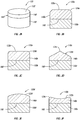
- FIG. 2A illustrates a the superhard stud element 120 which includes a superhard table 140 that has an approximately planar working surface 122.
- the superhard table 140 may be bonded or otherwise secured to a substrate 150.
- the superhard table 140 comprises polycrystalline diamond and the substrate 150 comprises cobalt-cemented tungsten carbide.
- the polycrystalline diamond table may be leached to at least partially remove or substantially completely remove a metal-solvent catalyst (e.g ., cobalt, iron, nickel, or alloys thereof) that was used to initially sinter precursor diamond particles to form the polycrystalline diamond.
- a metal-solvent catalyst e.g ., cobalt, iron, nickel, or alloys thereof
- an infiltrant used to re-infiltrate a preformed leached polycrystalline diamond table may be leached or otherwise removed to a selected depth from a working surface.
- the polycrystalline diamond may be un-leached and include a metal-solvent catalyst (e.g ., cobalt, iron, nickel, or alloys thereof) that was used to initially sinter the precursor diamond particles that form the polycrystalline diamond and/or an infiltrant used to re-infiltrate a preformed leached polycrystalline diamond table.
- a metal-solvent catalyst e.g ., cobalt, iron, nickel, or alloys thereof
- Examples of methods for fabricating the superhard bearing elements and superhard materials and/or structures from which the superhard bearing elements may be made are disclosed in U.S. Patent Nos. 7,866,418 ; 7,998,573 ; 8,034,136 ; and 8,236,074 ; the disclosure of each of the foregoing patents is incorporated herein, in its entirety, by this reference.
- the diamond particles that may be used to fabricate the superhard table 140 in a high-pressure/high-temperature process (“HPHT)" may exhibit a larger size and at least one relatively smaller size.
- HPHT high-pressure/high-temperature process
- the phrases “relatively larger” and “relatively smaller” refer to particle sizes (by any suitable method) that differ by at least a factor of two ( e.g ., 30 ⁇ m and 15 ⁇ m).
- the diamond particles may include a portion exhibiting a relatively larger size (e.g ., 70 ⁇ m, 60 ⁇ m, 50 ⁇ m, 40 ⁇ m, 30 ⁇ m, 20 ⁇ m, 15 ⁇ m, 12 ⁇ m, 10 ⁇ m, 8 ⁇ m) and another portion exhibiting at least one relatively smaller size (e.g ., 15 ⁇ m, 12 ⁇ m, 10 ⁇ m, 8 ⁇ m, 6 ⁇ m, 5 ⁇ m, 4 ⁇ m, 3 ⁇ m, 2 ⁇ m, 1 ⁇ m, 0.5 ⁇ m, less than 0.5 ⁇ m, 0.1 ⁇ m, less than 0.1 ⁇ m).
- a relatively larger size e.g ., 70 ⁇ m, 60 ⁇ m, 50 ⁇ m, 40 ⁇ m, 30 ⁇ m, 20 ⁇ m, 15 ⁇ m, 12 ⁇ m, 10 ⁇ m, 8 ⁇ m
- another portion exhibiting at least one relatively smaller size (e.g ., 15 ⁇ m
- the diamond particles may include a portion exhibiting a relatively larger size between about 10 ⁇ m and about 40 ⁇ m and another portion exhibiting a relatively smaller size between about 1 ⁇ m and 4 ⁇ m. In another embodiment, the diamond particles may include a portion exhibiting the relatively larger size between about 15 ⁇ m and about 50 ⁇ m and another portion exhibiting the relatively smaller size between about 5 ⁇ m and about 15 ⁇ m. In another embodiment, the relatively larger size diamond particles may have a ratio to the relatively smaller size diamond particles of at least 1.5. In some embodiments, the diamond particles may comprise three or more different sizes ( e.g ., one relatively larger size and two or more relatively smaller sizes), without limitation.
- the resulting polycrystalline diamond formed from HPHT sintering the aforementioned diamond particles may also exhibit the same or similar diamond grain size distributions and/or sizes as the aforementioned diamond particle distributions and particle sizes.
- the superhard bearing elements may be free-standing (e.g ., substrateless) and/or formed from a polycrystalline diamond body that is at least partially or fully leached to remove a metal-solvent catalyst initially used to sinter the polycrystalline diamond body.
- the superhard table 140 is bonded to the substrate 150.
- the superhard table 140 comprising polycrystalline diamond may be at least partially leached and bonded to the substrate 150 with an infiltrant exhibiting a selected viscosity, as described in U.S. Patent Application No. 13/275,372 , entitled “Polycrystalline Diamond Compacts, Related Products, And Methods Of Manufacture,” the entire contents of which are incorporated herein by this reference.
- At least partially leached polycrystalline diamond table may be fabricated by subjecting a plurality of diamond particles (e.g ., diamond particles having an average particle size between 0.5 ⁇ m to about 150 ⁇ m) to an HPHT sintering process in the presence of a catalyst, such as cobalt, nickel, iron, or an alloy of any of the preceding metals to facilitate intergrowth between the diamond particles and form a polycrystalline diamond table comprising bonded diamond grains defining interstitial regions having the catalyst disposed within at least a portion of the interstitial regions.
- a catalyst such as cobalt, nickel, iron, or an alloy of any of the preceding metals
- the as-sintered polycrystalline diamond table may be leached by immersion in an acid or subjected to another suitable process to remove at least a portion of the catalyst from the interstitial regions of the polycrystalline diamond table, as described above.
- the at least partially leached polycrystalline diamond table includes a plurality of interstitial regions that were previously occupied by a catalyst and form a network of at least partially interconnected pores.
- the sintered diamond grains of the at least partially leached polycrystalline diamond table may exhibit an average grain size of about 20 ⁇ m or less.
- the at least partially leached polycrystalline diamond table may be bonded to a substrate in an HPHT process via an infiltrant with a selected viscosity.
- an infiltrant may be selected that exhibits a viscosity that is less than a viscosity typically exhibited by a cobalt cementing constituent of typical cobalt-cemented tungsten carbide substrates (e.g ., 8% cobalt-cemented tungsten carbide to 13% cobalt-cemented tungsten carbide).
- the superhard table 140 may be a polycrystalline diamond table that has a thermally-stable region, having at least one low-carbon-solubility material disposed interstitially between bonded diamond grains thereof, as further described in U.S. Patent Application No. 13/027,954 , entitled "Polycrystalline Diamond Compact Including A Polycrystalline Diamond Table With A Thermally-Stable Region Having At Least One Low-Carbon-Solubility Material And Applications Therefor," the entire contents of which are incorporated herein by this reference.
- the low-carbon-solubility material may exhibit a melting temperature of about 1300 °C or less and a bulk modulus at 20 °C of less than about 150 GPa.
- the low-carbon-solubility in combination with the high diamond-to-diamond bond density of the diamond grains, may enable the low-carbon-solubility material to be extruded between the diamond grains and out of the polycrystalline diamond table before causing the polycrystalline diamond table to fail during operations due to interstitial-stress-related fracture.
- the polycrystalline diamond which may comprise the superhard table 140, may include bonded-together diamond grains having aluminum carbide disposed interstitially between the bonded-together diamond grains, as further described in U.S. Patent Application No. 13/100,388 , entitled “Polycrystalline Diamond Compact Including A Polycrystalline Diamond Table Containing Aluminum Carbide Therein And Applications Therefor," the entire contents of which are incorporated herein by this reference.
- superhard table 140 and substrate 150
- the embodiments of the invention are not so limited. More specifically, the superhard stud elements 120 may include any number of suitable superhard tables and substrates, which may vary from one embodiment to the next.
- the working surface 122 of the superhard table 140 may be substantially smooth ( i.e ., without texture or patterns thereon).
- a smooth working surface 122 may reduce one or more of fracturing, shredding, or grinding of the stock material as the stock material passes between the opposing crushing exteriors. Accordingly, reduction of the size of the solid objects included in the stock material may occur primarily through crushing and/or inter-particle breakage of the solid objects of the stock material, which may be desirable in some applications.
- the working surface 122 may include texture, pattern, or other features that may increase friction between the working surface 122 and the stock material. Consequently, the crushing exterior that includes such working surface 122 also may exhibit increased friction (e.g ., as compared to the superhard stud element 120 that has a substantially smooth working surface 122). Thus, the crushed material produced at least in part by such crushing exterior also may include pieces created due to a textured, patterned, or nonplanar crushing surface interacting with the stock material.
- the superhard table 140 may be bonded to the substrate 150 along an interface 160 (e.g ., as described above).
- the interface 160 may be substantially planar or flat.
- the interface 160 may include any number of suitable shapes, sizes, and configurations.
- the interface 160 may have a curved, grooved, textured, or recessed or otherwise nonplanar, where at least a portion of the interface 160 exhibits such a nonplanar geometry.
- the superhard table 140 may provide increased surface area that is exposed to the stock material (as compared with the surface area of the superhard table 140 that has a planar interface with the substrate 150).
- the superhard stud element 120 may have an approximately cylindrical shape. More specifically, the superhard table 140 and the substrate 150 may have approximately cylindrical shapes that form the overall cylindrical shape of the superhard stud element 120. It should be appreciated, however, that the superhard stud element 120 may have any number of suitable shapes, such as cubic, rectangular prismoid, as well as other three-dimensional shapes. Likewise, the working surface 122 of the superhard stud element 120 also may have any number of suitable shapes that may vary from one embodiment to another, and which may affect the mechanism of breakage or reduction in size of the stock material. Any of the superhard stud elements described herein may be used or included in the roll assembly 100 ( FIG. 1 ).
- FIG. 2B illustrates a superhard stud element 120a that includes a superhard table 140a, which has a working surface 122a.
- the superhard table 140a may be bonded or secured to the substrate 150a.
- the superhard stud element 120a and its materials, components, or elements e.g. , superhard tables
- the element may include a chamfer 124a, which may be positioned about the perimeter of the working surface 122a.
- An otherwise sharp corner formed between the working surface 122a and the peripheral surface of the superhard table 140a may be ground to form the chamfer 124a.
- an otherwise sharp corner may be impacted by stock material, which may chip or break the sharp corner.
- impact(s) also may produce a crack, emanating from or originating at the sharp corner, which may propagate through the superhard table 140.
- the chamfer 124a may reduce such chipping, breaking, cracking, and/or combinations thereof that may occur at an otherwise sharp corner, thereby increasing and/or improving the useful life of the superhard stud element 120a.
- FIG. 2C illustrates a superhard stud element 120b that has a superhard table 140b, which includes a working surface 122b.
- the superhard stud element 120b and its materials, components, or elements may be similar to or the same as any of the superhard stud elements 120, 120a ( FIG. 2A-2B ) and their respective materials, components, or elements.
- the superhard table 140b may be bonded or secured to a substrate 150b.
- the superhard stud element 120b may have a fillet or radius 124b, which may at least partially surround the perimeter of the working surface 122b.
- a fillet or radius 124b may at least partially surround the perimeter of the working surface 122b.
- an otherwise sharp corner formed between the working surface 122b and the peripheral surface of the superhard table 140b may be ground to form the radius 124b.
- the radius 124b may reduce chipping, breaking, cracking, or combinations thereof that may occur at a sharp corner.
- a superhard stud element 120c may include a superhard table 140c that has a conical working surface 122c. Except as otherwise described herein, the superhard stud element 120c and its materials, components, or elements (e.g. , superhard tables) may be similar to or the same as any of the superhard stud elements 120, 120a, 120b ( FIG. 2A-2C ) and their respective materials, components, or elements. For instance, the superhard table 140c may be bonded or secured to a substrate 150c.
- the conical working surface 122c may also include an apex 124c formed at an uppermost portion of the conical working surface 122c.
- the conical working surface 122c may have any number of suitable angles that may vary from one embodiment to the next.
- the apex 124c may be approximately aligned with a center axis of the superhard stud element 120c.
- the apex 124c may be offset from the center axis of the superhard stud element 120c.
- the crushing exterior (defined collectively by a plurality of stud elements attached to a roll) that includes the working surface 122c may have points or areas thereof that produce or apply differential force onto the solid objects of the stock material, as compared with other points or areas on the crushing exterior. More specifically, at the apex 124c, the distance or gap between the opposing crushing exteriors may be smaller than the gap at the lower portions of the working surface 122c. Consequently, the forces applied onto the solid objects of the stock material at the apex 124c may be greater than the forces applied onto the solid objects at other points or areas of the working surface 122c.
- the crushing exterior that has one or more conical working surface 122c may possibly produce crushed material that, on average, includes larger pieces or particles than the crushed material produced by the crushing exterior including the superhard stud elements with substantially flat or planar working surfaces.
- embodiments of the invention may include a superhard stud element 120d that has a superhard table 140d that with a generally dome-shaped or convex working surface 122d.
- the dome-shaped working surface 122d may be at least partially spherical.
- the superhard stud element 120d and its materials, components, or elements e.g ., superhard tables
- the superhard table 140d may be bonded or secured to a substrate 150d.
- the convex working surface 122d has an outward-facing or convex shape.
- the working surface 122d may have any suitable radius or other arcuate shape, which may vary from one implementation to the next.
- the convex working surface 122d may provide points or areas on the crushing exterior that may exert higher force onto the stock material than other areas on the crushing exterior.
- increasing the radius of the convex shape may possibly decrease the size of the pieces or particles of the crushed material produced by the crushing exteriors that include the dome-shaped working surface 122d.
- decreasing the radius of the convex working surface 122d may increase the size of the particles or pieces of the crushed material that may be produced by the crushing exteriors that include one or more superhard stud elements 120d with dome-shaped working surfaces 122d. Consequently, the average size of the particles and pieces of the crushed material may be adjusted by selecting or adjusting the radius of the working surface 122d of the superhard stud element 120d.
- a superhard stud element 120e that has a superhard table 140d having a concave working surface 122e is shown in FIG. 2F .
- the superhard stud element 120e and its materials, components, or elements may be similar to or the same as any of the superhard stud elements 120, 120a, 120b, 120c, 120d ( FIG. 2A-2E ) and their respective materials, components, or elements.
- the shape of the concave working surface 122e may be an approximately part spherical, concave recess in the superhard table 140e.
- the superhard stud element 120e may include a fillet or radius 124e, which may form uppermost portion(s) of the concave working surface 122e.
- the concave working surface 122e may produce points or areas on the crushing exterior that may exert higher force onto the solid objects of the stock material than other areas on the crushing exterior.
- the high force areas produced by the concave working surface 122e may be located or positioned about the perimeter of the superhard stud elements 120e.
- the pieces or particles crushed by the concave working surface 122e may have a maximum size that is less than the perimeter of the concave working surface 122e, which may be at least in part formed by the radius 124e.
- the perimeter of the concave working surface 122e may be increased. Conversely, to decrease the size of the pieces and pieces of the crushed material, the perimeter of the concave working surface 122e may be decreased.
- the superhard stud elements may be included in and may form or define at least a portion of one or more crushing exteriors.
- both opposing crushing exteriors include superhard stud elements.
- superhard stud elements may form substantially the entire crushing exterior.
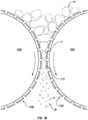
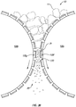
- FIGS. 3A and 3B illustrate roll assemblies roll assemblies 100a, 100b that have crushing exteriors that include superhard stud elements 120f, 120g, respectively.
- the crushing exteriors at least partially formed or defined by the superhard stud elements 120f, 120g may be aligned relative to each other and sized and configured to process the stock material in a manner described herein.
- the roll assemblies 100a, 100b and their respective materials, elements, or components may be similar to or the same as the materials, elements, or components, of the roll assembly 100 ( FIG. 1 ). Additionally, any of the superhard stud elements 120f, 120g and their respective materials, elements, or components may be similar to or the same as any of the superhard stud elements 120, 120a, 120b, 120c, 120d, 120e ( FIGS. 2A-2F ) and their respective materials, elements, or components.
- stock material 10 may be fed between the roll assemblies 100a and 100b.
- the opposing crushing exteriors of the roll assemblies 100a, 100b may compress, crush, break, shear, shred, grind the stock material 10 to produce crushed material 20, or combinations thereof.
- the crushing exterior of the roll assembly 100a includes the superhard stud elements 120f.
- the crushing exterior of the roll assembly 100b may include the superhard stud elements 120g.
- the superhard stud elements 120f and the superhard stud elements 120g may reduce the solid objects 11 to smaller particles or pieces 21, included in the crushed material 20.
- the roll assembly 100a may rotate in a counterclockwise direction while the roll assembly 100b may rotate in a clockwise direction. Accordingly, as the stock material 10 is fed between the roll assembly 100a and the roll assembly 100b, the stock material may move into the gap 170 between the roll assemblies 100a, 100b. Furthermore, as illustrated in FIG. 3B , the superhard stud elements 120f, 120g may reduce the size of the stock material 10 ( e.g ., solid objects 11) and produce the pieces 21 of the crushed material, in a manner described above.
- the superhard stud elements 120f, 120g may reduce the size of the stock material 10 (e.g ., solid objects 11) and produce the pieces 21 of the crushed material, in a manner described above.
- the particular mechanism of reducing the size of the stock material 10 e.g ., crushing, breaking (including inter-particle breaking), compressing, shearing, shredding, grinding, or combinations thereof
- the mechanism of reducing the size of the solid objects 11 and/or the size of the pieces 21 produced therefrom may depend, among other things, on the geometry of the superhard stud elements 120f, 120g, the size of the gap 170, the size of the roll assemblies 100a, 100b ( e.g ., length to diameter ratio), the properties of the stock material 10, relative speeds of rotation of the roll assemblies 100a, 100b, or combinations thereof.
- the stock material 10 may be passed between one or more of the roll assemblies 100a, 100b and may be reduced to the pieces 21 of desired size.
- each of the roll assembly 100a and roll assembly 100b may be included in an HPGR apparatus 200.
- each of the roll assembly 100a and roll assembly 100b may include a shaft, such as a shaft 210.
- the shaft 210 may rotatably secure the roll assembly 100a and/or the roll assembly 100b to and/or within a housing 220 of the HPGR apparatus 200.
- the shaft 210 and/or the housing 220 may include one or more bearings (e.g ., radial bearings, tapered bearings, journal bearings, etc.) that may rotatably secure the shaft 210 to the housing 220.
- one of the roll assemblies 100a or 100b may remain stationary ( e.g ., may be fixedly mounted in the housing 220).
- the HPGR apparatus 200 may include motors 230 that are each operably coupled to and rotate the roll assembly 100a and/or roll assembly 100b in opposite directions, which may generate relative movement of the opposing crushing exteriors of the roll assembly 100a and roll assembly 100b.
- the roll assembly 100a and roll assembly 100b may be rotated in the same direction but at different speeds.
- the roll assembly 100a may be rotated in a counterclockwise direction at a first speed
- the roll assembly 100b may be rotated in the counterclockwise direction at a second speed (e.g ., the first speed may be greater than the second speed).
- the stock material 10 may be fed between the roll assembly 100a and the roll assembly 100b of the HPGR apparatus 200, which may produce the crushed material, in a manner described above.
- the HPGR apparatus 200 also may include a material delivery system 240, which may deliver the stock material 10 to a desired location, such as to or near a location of the roll assemblies 100a and 100b, such that the stock material 10 may be processed by the roll assemblies 100a and 100b.
- the delivery system 240 may be a conveyor or a belt that may transfer the stock material 10 to or near a desired location in the HPGR apparatus 200, such as at the roll assembly 110a or between the roll assembly 110a and 110b.
- the delivery system 240 may be a chute or other channel that may deliver the stock material 10 to a desired location in the HPGR apparatus 200.
- the stock material 10 also may be delivered by a cart, overhead crane ( e.g ., via a carriage), a hopper, and any number of suitable delivery systems 240.
- the stock material 10 may be unprocessed (e.g ., the stock material 10 may come directly from a mine) and may be carried by the delivery system 240 for processing by the HPGR apparatus 200.
- at least a portion of the stock material 10 may be preprocessed before being delivered to the HPGR apparatus 200.
- solid objects making up at least a portion of the stock material 10 may be reduced in size to a desired size of average size, to facilitate further processing by the HPGR apparatus 200.
- the stock material 10 may be processed by the HPGR apparatus 200 to produce crushed material having particles or pieces of a particular or desirable average size.
Landscapes
- Engineering & Computer Science (AREA)
- Food Science & Technology (AREA)
- Powder Metallurgy (AREA)
- Crushing And Grinding (AREA)
- Earth Drilling (AREA)
Description
- High pressure grinding roll ("HPRG") apparatuses are commonly used for reducing the size of larger solid objects in a stock material, such as rocks, stones, and ore, into smaller pieces or particles. For instance, the HPRG apparatus may include two opposing roll assemblies that may rotate in opposite directions. Furthermore, the two opposing roll assemblies may be spaced apart by a predetermined gap therebetween. For example, ore may be fed between the roll assemblies, which may crush the ore. Specifically, as the roll assemblies rotate, the ore may enter or be forced into the gap between the roll assemblies and may be crushed in the gap by the roll assemblies. As noted above, crushing the ore may reduce the size of the solid objects included in the ore to smaller pieces or particles.
- In some instances, the roll assemblies of the HPGR apparatus may include studs or other protrusions secured to a roll body. As the roll assemblies rotate, the studs may compress and crush the ore therebetween.
WO 2011/072754 discloses a grinding roll for heavy wear operation andUS 2008/041995 discloses a roll assembly for reducing size of a stock material. - Manufacturers and users of HPGR apparatuses continue to seek improved roll assemblies to extend the useful life of such HPGR apparatuses.
- Embodiments of the invention are directed to a roll assembly for reducing size of a stock material, a grinding roll apparatus and a method of processing a stock material according to the claims. The roll assembly of the invention exhibits improved wear resistance of stud elements and may improve and/or increase the useful life of HPRG apparatuses.
- The invention concerns a roll assembly for reducing size of a stock material according to claim 1. The roll assembly includes a roll body having an outer cylindrical surface, and a plurality of superhard stud elements secured to the roll body. Each of the plurality of superhard stud elements includes a superhard element including a convex working surface. The convex working surfaces of the plurality of superhard stud elements at least partially define a crushing exterior of the roll assembly.
- The invention also concerns a HPGR apparatus for processing a stock material according to claim 5. An HPGR apparatus includes a first roll assembly including a first crushing exterior and a second roll assembly positioned adjacent to the first roll assembly to define a gap therebetween. The first roll assembly includes a first plurality of superhard stud elements each including a superhard element. The superhard element includes a first working surface, with the first working surfaces of the first plurality of superhard stud elements at least partially forming the first crushing exterior. The second roll assembly includes a second plurality of stud elements each of which includes a second working surface, with the second working surfaces of the second plurality of stud elements forming a second crushing exterior. The HPGR apparatus further includes a motor operably connected to and configured to rotate at least one of the first roll assembly or the second roll assembly.
- The invention also relates to a method of processing a stock material according to claim 9. is disclosed. A method of processing stock material includes rotating a first plurality of superhard stud elements about a first axis in a first direction, with each of the first plurality of superhard stud elements includes a superhard table that has a first working surface. The method further includes rotating a second plurality of superhard stud elements about a second axis in a second direction, with each of the second plurality of superhard stud elements including a superhard table that has a second working surface. The method additionally includes reducing the size of the solid object included in the stock material by contacting the stock material with the first working surfaces and/or the second working surfaces.
- Features from any of the disclosed embodiments may be used in combination with one another, without limitation. In addition, other features and advantages of the present disclosure will become apparent to those of ordinary skill in the art through consideration of the following detailed description and the accompanying drawings.
- The drawings illustrate several embodiments of the invention, wherein identical reference numerals refer to identical or similar elements or features in different views or embodiments shown in the drawings.
-
FIG. 1 is an isometric view of a roll assembly. -
FIG. 2A is an isometric view of a superhard stud element. -
FIG. 2B is a cross-sectional view of a superhard stud element. -
FIG. 2C is a cross-sectional view of a superhard stud element. -
FIG. 2D is a cross-sectional view of a superhard stud element. -
FIG. 2E is a cross-sectional view of a superhard stud element. -
FIG. 2F is a cross-sectional view of a superhard stud element. -
FIG. 3A is a side view of opposing roll assemblies in a first position during operation of processing stock material. -
FIG. 3B is a side view of opposing roll assemblies in a second position during operation of processing stock material. -
FIG. 4 is an isometric view of a HPGR apparatus. - Embodiments of the invention are directed to roll assemblies configured to exhibit improved wear resistance of stud elements, HPRG apparatuses, and method of use. The roll assemblies disclosed herein may improve and/or increase the useful life of HPRG apparatuses. In an embodiment, one or more stud elements may include superhard material, which may provide superior wear resistance characteristics and may increase the useful life of the rolls assemblies and HPGR apparatuses.
- A roll assembly may have one or more superhard stud elements, which may include superhard material. As used herein, a "superhard stud element" is a stud element including a working surface that is made from a material exhibiting a hardness that exceeds the hardness of tungsten carbide. In any of the embodiments disclosed herein, the superhard bearing elements may include one or more superhard materials, such as polycrystalline diamond, polycrystalline cubic boron nitride, silicon carbide, tungsten carbide, or any combination of the foregoing superhard materials. In an embodiment, the superhard stud elements may include a substrate and a superhard material bonded to the substrate.
- A roll assembly may include a plurality of superhard stud elements secured to a roll body, as further described below. The roll body may be substantially cylindrical and may have a length and a diameter that may vary from one embodiment to the next and may depend on the particular application. Furthermore, the superhard stud elements may be located on the roll body in any number of suitable configurations and patterns and may, collectively, form or define a crushing exterior of the roll assembly. For instance, the roll body may include multiple rows of superhard stud elements, and such rows may surround substantially the entire circumference of the roll body.
-
FIG. 1 illustrates an embodiment of aroll assembly 100 that may-includes aroll body 110 and crushing exterior formed by and/or on theroll body 110. The superhard crushing exterior of theroll body 110 may reduce the size of the solid objects that comprise stock material by compressing, crushing, shearing, shredding, and/or grinding, solid objects included in the stock material. For ease of description, reference will be made to a "crushing exterior." It should be appreciated that the crushing exterior of theroll body 110 may compress the stock material, crush the stock material, shear the stock material, shred the stock material, grind the stock material, or combinations thereof, as may be suitable for a particular application, which may vary from one embodiment to another. - The crushing exterior is formed by one or more protrusions such as
superhard stud elements 120. More specifically, one, some, or all of thesuperhard stud elements 120 include superhard material that has a workingsurface 122. As used herein, the term "working surface" is intended to mean any surface of the stud element that contacts the stock material. Accordingly, the crushing exterior also may include superhard material. In particular, as noted above, the superhard material may include polycrystalline diamond which may provide superior wear resistance for the crushing exterior and may improve and/or extend the useful life of theroll assembly 100. It should be noted that all or only some of thesuperhard stud elements 120 may comprise polycrystalline diamond. For example, other ones of the superhard stud elements (e.g., every other one, two, or three superhard stud element(s)) may be a tungsten carbide stud element 120'. - According to the invention, the
roll body 110 has anouter surface 130, which has a substantially cylindrical shape. In addition, theroll body 110 may be solid, hollow, or tubular (e.g., theroll body 110 may have a cored-out inner cavity or space). In any event, theroll body 110 may have sufficient strength and rigidity to compress, crush, shear, shred, and/or grind the stock material, as may be suitable for a particular application. - Similarly, the crushing exterior may approximate a cylindrical shape (e.g., the crushing exterior formed by the working
surfaces 122 of thesuperhard stud elements 120 may lay approximately along an exterior of an imaginary cylinder). For instance, thesuperhard stud elements 120 may be mounted about thecylindrical roll body 110. As such, the workingsurface 122, collectively, may form an approximately cylindrical crushing exterior. It may be appreciated that the particular shape of the crushing exterior formed by thesuperhard stud elements 120 may depend on the shape of the workingsurfaces 122 as well as on the orientation of thesuperhard stud elements 120 relative to theroll body 110. In any case, the workingsurface 122 may have a suitable shape and orientation to form the crushing exterior that may compress, crush, and/or shear the stock material. - In an embodiment, the
roll body 110 may include recesses in theouter surface 130 thereof, which may receive and accommodate thesuperhard stud elements 120. For example, thesuperhard stud elements 120 may be at least partially secured to roll body 110 (e.g., within corresponding recesses) via brazing, press-fitting, threadedly attaching, fastening with a fastener, combinations of the foregoing, or another suitable technique. In particular, thesuperhard stud elements 120 may be sufficiently secured to theroll body 110, such as to withstand normal operating forces experience thereby. - Furthermore, in an embodiment, the recesses may at least partially orient the
superhard stud elements 120 relative to theroll body 110. For instance, thesuperhard stud elements 120 may have an approximately cylindrical shape, which may be oriented within circular recesses. Particularly, thesuperhard stud element 120 may be oriented approximately perpendicular to a tangent of theouter surface 130 at the location of the recess. In other words, thesuperhard stud elements 120 may be approximately radially aligned with a center of theroll body 110. - Moreover, the
superhard stud elements 120 may have any number of suitable patterns and/or configurations on theroll body 110, which may vary from one embodiment to the next. For example, as mentioned above, thesuperhard stud elements 120 may form rows along theroll body 110, and such rows may surround the circumference of thecylindrical roll body 110. In addition, the rows may be aligned with one another (i.e., thesuperhard stud elements 120 in one row may be aligned with thesuperhard stud elements 120 and the adjacent row). Alternatively, the rows may be offset from one another, such that thesuperhard stud elements 120 in one row are offset from thesuperhard stud elements 120 in an adjacent row along the length of theroll body 110. - Also, the rows of the
superhard stud elements 120 may be approximately oriented along the length of theroll body 110. Accordingly, rotation of theroll body 110 about a center axis thereof may produce rotation of the row of thesuperhard stud elements 120 about the center axis of theroll body 110. In additional or alternative embodiments, the row of thesuperhard stud elements 120 may be skewed relative to the length of the roll body 110 (i.e., the row of thesuperhard stud elements 120 may approximately form a spiral about theouter surface 130 of the roll body 110). Consequently, in at least one embodiment, the row of thesuperhard stud elements 120 may have an approximately spiral rotation relative to the center axis of theroll body 110. In any event, the crushing exterior of theroll assembly 100 may rotate about the center axis of theroll body 110 and may compress, crush, shear, shred, grind, or combinations thereof the solid objects of the stock material. - Although in some embodiments the
superhard stud elements 120 may form one or more rows on theroll body 110, it should be appreciated that embodiments of the invention need not be so limited. More specifically, thesuperhard stud elements 120 may form any number of patterns, which may vary from one embodiment to the next. For example, thesuperhard stud elements 120 may form irregular patterns or may be randomly located or positioned (i.e., without any particular pattern) on theroll body 110. In other embodiments, thesuperhard stud elements 120 may form regular patterns and may be intermixed with non-superhard studs (e.g., tungsten carbide studs). For example, every other or every third row on theroll body 110 may includesuperhard stud elements 120 and remaining rows may have tungsten carbide stud elements or other less superhard stud elements. - Furthermore, the spacing between adjacent
superhard stud elements 120 also may vary from one embodiment to another. In an embodiment, some or all of thesuperhard stud elements 120 may be spaced sufficiently close together, such that the spacing between the adjacent superhard stud elements 120 (or in other embodiments non-superhard stud elements) is less than the size of a superhard stud element that may be located on an opposing roll assembly (described below). Alternatively, the spacing between some or all of the adjacentsuperhard stud elements 120 may be greater than one or more of the opposing superhard stud elements. - In an embodiment, the stock material may be compressed, crushed, sheared, shredded, ground, or combinations thereof between the crushing exterior of the
roll assembly 100 and an opposing crushing exterior. As noted above, the opposing crushing exterior also may include one or more stud elements. Consequently, in an embodiment, stock material may be compressed, crushed, sheared, shredded, ground, or combinations thereof between thesuperhard stud elements 120 and the stud elements of the opposing crushing exterior. Thesuperhard stud elements 120 and the opposing stud elements may be spaced in a manner that thesuperhard stud elements 120 and the opposing stud elements at least partially overlap one another. - In additional or alternative embodiments, at least some of the opposing stud elements may at least partially fit into spaces between the
superhard stud elements 120 of theroll assembly 100. As such, the solid objects of the stock material may be compressed, crushed, sheared, shredded, ground between the opposing stud elements and thesuperhard stud elements 120 by pressing the solid objects into the spaces between thesuperhard stud elements 120, or combinations thereof. Likewise, in an embodiment, at least some of thesuperhard stud elements 120 may fit into spaces between the opposing stud elements, thereby compressing, crushing, shearing, shredding, and/or grinding solid objects of the stock material by pressing the solid objects into the spaces between the opposing stud elements and/or into the spaces between thesuperhard stud elements 120. In an embodiment, the size of the pieces or particles of a crushed material produced from the stock material may be at least partially controlled by choosing a suitable pattern and/or spacing of thesuperhard stud elements 120 on theroll body 110 as well as by choosing an suitable gap between the crushing exterior of theroll assembly 100 and the opposing crushing exterior of another roll assembly. As used herein, the term "crushed material" refers to the material produced from the stock material by, among other things, at least one of compressing, crushing, shearing, shredding, or grinding the stock material by and/or between the crushing exterior of theroll assembly 100 and the opposing crushing exterior. For instance, the crushed material may be produced by passing the stock material through the HPGR apparatus, as described below. - Although the opposing crushing exterior described above includes one or more opposing stud elements, it should be appreciated that embodiments of the invention are not so limited. For instance, the opposing crushing exterior may be substantially uniform (e.g., may comprise an outer surface of a roll body of an opposing roll assembly), may include welded-on ridges or spots, as well as may have any number of various configurations and features that may allow compressing and/or shearing of the stock material between the opposing crushing exterior and the crushing exterior of the
roll assembly 100. Furthermore, while in one or more embodiments, the opposing crushing exterior may be included in an opposing roll assembly, in additional or alternative embodiments, the opposing crushing exterior may be secured to or integrated with a stationary component or element. - Moreover, the opposing crushing exterior may have any number of suitable shapes. In an embodiment, the opposing crushing exterior may be approximately cylindrical (i.e., similar in shape to the outer surface 130). Alternatively or additionally, the opposing crushing exterior may have a shape that approximates a portion of an inner surface of a cylindrical tube. In other embodiments, the opposing crushing exterior may be approximately planar, or arcuate. In any event, the opposing crushing exterior and the crushing exterior of the
roll assembly 100 may be suitable to allow compression and/or shearing of the stock material therebetween. - In an embodiment, the
roll assembly 100 and the opposing roll assembly may rotate about respective center axes, in opposite directions relative to one another. For example, theroll assembly 100 may rotate in a clockwise direction, while the opposing roll assembly may rotate in a counterclockwise direction (i.e., the crushing exterior of theroll assembly 100 and that crushing exterior of the opposing roll assembly may move in opposite directions). Moreover, theroll assembly 100 and the opposing roll assembly may rotate at approximately the same speed. Alternatively, theroll assembly 100 and the opposing roll assembly may rotate at different speeds. Furthermore, in one embodiment, the crushing exterior of the opposing roll assembly or the crushing exterior of theroll assembly 100 may remain stationary while the other of the crushing exterior of the opposing roll assembly or the crushing exterior of theroll assembly 100 may move or rotate. - In an embodiment, movement of the crushing exterior of the
roll assembly 100 and the opposing crushing exterior at different speeds may facilitate shearing, shredding, grinding of the stock material, or combinations thereof. For instance, friction between the stock material and the crushing exterior of theroll assembly 100 and the opposing crushing exterior may impart compressive/shearing forces on to the stock material, which may fracture, break apart, crush the stock material, or combinations thereof as the stock material passes between the crushing exterior of theroll assembly 100 and the opposing crushing exterior. In addition, in an embodiment, the crushing exterior of theroll assembly 100 and/or the opposing crushing exterior may frictionally slip relative to the stock material located therebetween, thereby grinding or sliding against at least a portion of the stock material. - In any event, as the stock material passes between the crushing exterior of the
roll assembly 100 and the opposing crushing exterior, the stock material may experience inter-particle breakage that may reduce the size of the solid objects of the stock material, to smaller pieces or particles included in the crushed material. Hence, at least a portion of the pieces or particles included in the crushed material may be formed from breakage produced by tension/compression between other particles, such as between the surrounding particles, which may be distinct from single-particle breakage (e.g., breakage into two pieces of a single particle crushed between surfaces of a crushing machine). - It should be appreciated, that the
superhard stud elements 120 may include various features that may facilitate various modes of breakage and/or reduction in size of the solid objects included in the stock material.FIG. 2A illustrates a thesuperhard stud element 120 which includes a superhard table 140 that has an approximately planar workingsurface 122. The superhard table 140 may be bonded or otherwise secured to asubstrate 150. - The superhard table 140 comprises polycrystalline diamond and the
substrate 150 comprises cobalt-cemented tungsten carbide. Furthermore, in any of the embodiments disclosed herein, the polycrystalline diamond table may be leached to at least partially remove or substantially completely remove a metal-solvent catalyst (e.g., cobalt, iron, nickel, or alloys thereof) that was used to initially sinter precursor diamond particles to form the polycrystalline diamond. In another embodiment, an infiltrant used to re-infiltrate a preformed leached polycrystalline diamond table may be leached or otherwise removed to a selected depth from a working surface. Moreover, in any of the embodiments disclosed herein, the polycrystalline diamond may be un-leached and include a metal-solvent catalyst (e.g., cobalt, iron, nickel, or alloys thereof) that was used to initially sinter the precursor diamond particles that form the polycrystalline diamond and/or an infiltrant used to re-infiltrate a preformed leached polycrystalline diamond table. Examples of methods for fabricating the superhard bearing elements and superhard materials and/or structures from which the superhard bearing elements may be made are disclosed inU.S. Patent Nos. 7,866,418 ;7,998,573 ;8,034,136 ; and8,236,074 ; the disclosure of each of the foregoing patents is incorporated herein, in its entirety, by this reference. - The diamond particles that may be used to fabricate the superhard table 140 in a high-pressure/high-temperature process ("HPHT)" may exhibit a larger size and at least one relatively smaller size. As used herein, the phrases "relatively larger" and "relatively smaller" refer to particle sizes (by any suitable method) that differ by at least a factor of two (e.g., 30 µm and 15 µm). According to various embodiments, the diamond particles may include a portion exhibiting a relatively larger size (e.g., 70 µm, 60 µm, 50 µm, 40 µm, 30 µm, 20 µm, 15 µm, 12 µm, 10 µm, 8 µm) and another portion exhibiting at least one relatively smaller size (e.g., 15 µm, 12 µm, 10 µm, 8 µm, 6 µm, 5 µm, 4 µm, 3 µm, 2 µm, 1 µm, 0.5 µm, less than 0.5 µm, 0.1 µm, less than 0.1 µm). In an embodiment, the diamond particles may include a portion exhibiting a relatively larger size between about 10 µm and about 40 µm and another portion exhibiting a relatively smaller size between about 1 µm and 4 µm. In another embodiment, the diamond particles may include a portion exhibiting the relatively larger size between about 15 µm and about 50 µm and another portion exhibiting the relatively smaller size between about 5 µm and about 15 µm. In another embodiment, the relatively larger size diamond particles may have a ratio to the relatively smaller size diamond particles of at least 1.5. In some embodiments, the diamond particles may comprise three or more different sizes (e.g., one relatively larger size and two or more relatively smaller sizes), without limitation. The resulting polycrystalline diamond formed from HPHT sintering the aforementioned diamond particles may also exhibit the same or similar diamond grain size distributions and/or sizes as the aforementioned diamond particle distributions and particle sizes. Additionally, in any of the embodiments disclosed herein, the superhard bearing elements may be free-standing (e.g., substrateless) and/or formed from a polycrystalline diamond body that is at least partially or fully leached to remove a metal-solvent catalyst initially used to sinter the polycrystalline diamond body.
- As noted above, the superhard table 140 is bonded to the
substrate 150. For instance, the superhard table 140 comprising polycrystalline diamond may be at least partially leached and bonded to thesubstrate 150 with an infiltrant exhibiting a selected viscosity, as described inU.S. Patent Application No. 13/275,372 , entitled "Polycrystalline Diamond Compacts, Related Products, And Methods Of Manufacture," the entire contents of which are incorporated herein by this reference. In an embodiment, at least partially leached polycrystalline diamond table may be fabricated by subjecting a plurality of diamond particles (e.g., diamond particles having an average particle size between 0.5 µm to about 150 µm) to an HPHT sintering process in the presence of a catalyst, such as cobalt, nickel, iron, or an alloy of any of the preceding metals to facilitate intergrowth between the diamond particles and form a polycrystalline diamond table comprising bonded diamond grains defining interstitial regions having the catalyst disposed within at least a portion of the interstitial regions. The as-sintered polycrystalline diamond table may be leached by immersion in an acid or subjected to another suitable process to remove at least a portion of the catalyst from the interstitial regions of the polycrystalline diamond table, as described above. The at least partially leached polycrystalline diamond table includes a plurality of interstitial regions that were previously occupied by a catalyst and form a network of at least partially interconnected pores. In an embodiment, the sintered diamond grains of the at least partially leached polycrystalline diamond table may exhibit an average grain size of about 20 µm or less. Subsequent to leaching the polycrystalline diamond table, the at least partially leached polycrystalline diamond table may be bonded to a substrate in an HPHT process via an infiltrant with a selected viscosity. For example, an infiltrant may be selected that exhibits a viscosity that is less than a viscosity typically exhibited by a cobalt cementing constituent of typical cobalt-cemented tungsten carbide substrates (e.g., 8% cobalt-cemented tungsten carbide to 13% cobalt-cemented tungsten carbide). - Additionally or alternatively, the superhard table 140 may be a polycrystalline diamond table that has a thermally-stable region, having at least one low-carbon-solubility material disposed interstitially between bonded diamond grains thereof, as further described in
U.S. Patent Application No. 13/027,954 , entitled "Polycrystalline Diamond Compact Including A Polycrystalline Diamond Table With A Thermally-Stable Region Having At Least One Low-Carbon-Solubility Material And Applications Therefor," the entire contents of which are incorporated herein by this reference. The low-carbon-solubility material may exhibit a melting temperature of about 1300 °C or less and a bulk modulus at 20 °C of less than about 150 GPa. The low-carbon-solubility, in combination with the high diamond-to-diamond bond density of the diamond grains, may enable the low-carbon-solubility material to be extruded between the diamond grains and out of the polycrystalline diamond table before causing the polycrystalline diamond table to fail during operations due to interstitial-stress-related fracture. - In some embodiments, the polycrystalline diamond, which may comprise the superhard table 140, may include bonded-together diamond grains having aluminum carbide disposed interstitially between the bonded-together diamond grains, as further described in
U.S. Patent Application No. 13/100,388 , entitled "Polycrystalline Diamond Compact Including A Polycrystalline Diamond Table Containing Aluminum Carbide Therein And Applications Therefor," the entire contents of which are incorporated herein by this reference. - It should be appreciated that, while the above description provides specific examples of superhard table 140 and
substrate 150, the embodiments of the invention are not so limited. More specifically, thesuperhard stud elements 120 may include any number of suitable superhard tables and substrates, which may vary from one embodiment to the next. - Furthermore, in an embodiment, the working
surface 122 of the superhard table 140 may be substantially smooth (i.e., without texture or patterns thereon). Asmooth working surface 122 may reduce one or more of fracturing, shredding, or grinding of the stock material as the stock material passes between the opposing crushing exteriors. Accordingly, reduction of the size of the solid objects included in the stock material may occur primarily through crushing and/or inter-particle breakage of the solid objects of the stock material, which may be desirable in some applications. - In additional or alternative embodiments, at least a portion of the working
surface 122 may include texture, pattern, or other features that may increase friction between the workingsurface 122 and the stock material. Consequently, the crushing exterior that includes such workingsurface 122 also may exhibit increased friction (e.g., as compared to thesuperhard stud element 120 that has a substantially smooth working surface 122). Thus, the crushed material produced at least in part by such crushing exterior also may include pieces created due to a textured, patterned, or nonplanar crushing surface interacting with the stock material. - The superhard table 140 may be bonded to the
substrate 150 along an interface 160 (e.g., as described above). In one or more embodiments, theinterface 160 may be substantially planar or flat. In additional or alternative embodiments, however, theinterface 160 may include any number of suitable shapes, sizes, and configurations. For instance, theinterface 160 may have a curved, grooved, textured, or recessed or otherwise nonplanar, where at least a portion of theinterface 160 exhibits such a nonplanar geometry. As such, in some embodiments, the superhard table 140 may provide increased surface area that is exposed to the stock material (as compared with the surface area of the superhard table 140 that has a planar interface with the substrate 150). - Furthermore, as described above, the
superhard stud element 120 may have an approximately cylindrical shape. More specifically, the superhard table 140 and thesubstrate 150 may have approximately cylindrical shapes that form the overall cylindrical shape of thesuperhard stud element 120. It should be appreciated, however, that thesuperhard stud element 120 may have any number of suitable shapes, such as cubic, rectangular prismoid, as well as other three-dimensional shapes. Likewise, the workingsurface 122 of thesuperhard stud element 120 also may have any number of suitable shapes that may vary from one embodiment to another, and which may affect the mechanism of breakage or reduction in size of the stock material. Any of the superhard stud elements described herein may be used or included in the roll assembly 100 (FIG. 1 ). -
FIG. 2B , illustrates asuperhard stud element 120a that includes a superhard table 140a, which has a workingsurface 122a. For example, the superhard table 140a may be bonded or secured to thesubstrate 150a. Except as otherwise described herein, thesuperhard stud element 120a and its materials, components, or elements (e.g., superhard tables) may be similar to or the same as the superhard stud element 120 (FIG. 2A ) and its materials, components, or elements. The element may include achamfer 124a, which may be positioned about the perimeter of the workingsurface 122a. An otherwise sharp corner formed between the workingsurface 122a and the peripheral surface of the superhard table 140a may be ground to form thechamfer 124a. - For instance, as the working
surface 122a (or the crushing exterior that includes that workingsurface 122a) makes contact with the stock material, an otherwise sharp corner may be impacted by stock material, which may chip or break the sharp corner. In addition, such impact(s) also may produce a crack, emanating from or originating at the sharp corner, which may propagate through the superhard table 140. Thechamfer 124a may reduce such chipping, breaking, cracking, and/or combinations thereof that may occur at an otherwise sharp corner, thereby increasing and/or improving the useful life of thesuperhard stud element 120a. -
FIG. 2C , illustrates asuperhard stud element 120b that has a superhard table 140b, which includes a working surface 122b. Except as otherwise described herein, thesuperhard stud element 120b and its materials, components, or elements (e.g., superhard tables) may be similar to or the same as any of thesuperhard stud elements FIG. 2A-2B ) and their respective materials, components, or elements. For instance, the superhard table 140b may be bonded or secured to asubstrate 150b. - In addition, the
superhard stud element 120b may have a fillet orradius 124b, which may at least partially surround the perimeter of the working surface 122b. For example, an otherwise sharp corner formed between the working surface 122b and the peripheral surface of the superhard table 140b may be ground to form theradius 124b. Similar to thechamfer 124a (FIG. 2B ), theradius 124b may reduce chipping, breaking, cracking, or combinations thereof that may occur at a sharp corner. - As illustrated in
FIG. 2D , asuperhard stud element 120c may include a superhard table 140c that has a conical workingsurface 122c. Except as otherwise described herein, thesuperhard stud element 120c and its materials, components, or elements (e.g., superhard tables) may be similar to or the same as any of thesuperhard stud elements FIG. 2A-2C ) and their respective materials, components, or elements. For instance, the superhard table 140c may be bonded or secured to asubstrate 150c. - The conical working
surface 122c may also include an apex 124c formed at an uppermost portion of the conical workingsurface 122c. The conical workingsurface 122c may have any number of suitable angles that may vary from one embodiment to the next. Moreover, the apex 124c may be approximately aligned with a center axis of thesuperhard stud element 120c. Alternatively, the apex 124c may be offset from the center axis of thesuperhard stud element 120c. - The crushing exterior (defined collectively by a plurality of stud elements attached to a roll) that includes the working
surface 122c may have points or areas thereof that produce or apply differential force onto the solid objects of the stock material, as compared with other points or areas on the crushing exterior. More specifically, at the apex 124c, the distance or gap between the opposing crushing exteriors may be smaller than the gap at the lower portions of the workingsurface 122c. Consequently, the forces applied onto the solid objects of the stock material at the apex 124c may be greater than the forces applied onto the solid objects at other points or areas of the workingsurface 122c. In one example, the crushing exterior that has one or more conical workingsurface 122c may possibly produce crushed material that, on average, includes larger pieces or particles than the crushed material produced by the crushing exterior including the superhard stud elements with substantially flat or planar working surfaces. - As illustrated in
FIG. 2E , embodiments of the invention may include asuperhard stud element 120d that has a superhard table 140d that with a generally dome-shaped or convex working surface 122d. In an embodiment, the dome-shaped working surface 122d may be at least partially spherical. Except as otherwise described herein, thesuperhard stud element 120d and its materials, components, or elements (e.g., superhard tables) may be similar to or the same as any of thesuperhard stud elements FIG. 2A-2D ) and their respective materials, components, or elements. For example, the superhard table 140d may be bonded or secured to asubstrate 150d. - The convex working surface 122d has an outward-facing or convex shape. The working surface 122d may have any suitable radius or other arcuate shape, which may vary from one implementation to the next. In any event, similar to the
conical working surface 122c (FIG. 2D ), the convex working surface 122d may provide points or areas on the crushing exterior that may exert higher force onto the stock material than other areas on the crushing exterior. - Moreover, in an embodiment, increasing the radius of the convex shape may possibly decrease the size of the pieces or particles of the crushed material produced by the crushing exteriors that include the dome-shaped working surface 122d. Conversely, it is believed that decreasing the radius of the convex working surface 122d may increase the size of the particles or pieces of the crushed material that may be produced by the crushing exteriors that include one or more
superhard stud elements 120d with dome-shaped working surfaces 122d. Consequently, the average size of the particles and pieces of the crushed material may be adjusted by selecting or adjusting the radius of the working surface 122d of thesuperhard stud element 120d. - A
superhard stud element 120e that has a superhard table 140d having aconcave working surface 122e is shown inFIG. 2F . Except as otherwise described herein, thesuperhard stud element 120e and its materials, components, or elements (e.g., superhard tables) may be similar to or the same as any of thesuperhard stud elements FIG. 2A-2E ) and their respective materials, components, or elements. The shape of theconcave working surface 122e may be an approximately part spherical, concave recess in the superhard table 140e. Furthermore, thesuperhard stud element 120e may include a fillet orradius 124e, which may form uppermost portion(s) of theconcave working surface 122e. - Accordingly, similar to the convex working surface 122d (
FIG. 2E ), theconcave working surface 122e may produce points or areas on the crushing exterior that may exert higher force onto the solid objects of the stock material than other areas on the crushing exterior. In contrast to the convex working surface 122d (FIG. 2E ), however, the high force areas produced by theconcave working surface 122e may be located or positioned about the perimeter of thesuperhard stud elements 120e. Thus, for instance, the pieces or particles crushed by theconcave working surface 122e may have a maximum size that is less than the perimeter of theconcave working surface 122e, which may be at least in part formed by theradius 124e. As such, it is believed that to increase the maximum and/or average size of the pieces and particles of the crushed material, the perimeter of theconcave working surface 122e may be increased. Conversely, to decrease the size of the pieces and pieces of the crushed material, the perimeter of theconcave working surface 122e may be decreased. - In any case, as mentioned above, the superhard stud elements may be included in and may form or define at least a portion of one or more crushing exteriors. In an embodiment, both opposing crushing exteriors include superhard stud elements. In some embodiments, superhard stud elements may form substantially the entire crushing exterior.
FIGS. 3A and3B illustrate roll assemblies rollassemblies superhard stud elements superhard stud elements roll assemblies FIG. 1 ). Additionally, any of thesuperhard stud elements superhard stud elements FIGS. 2A-2F ) and their respective materials, elements, or components. - As illustrated in
FIG. 3A ,stock material 10 may be fed between theroll assemblies stock material 10 passes through agap 170 between theroll assembly 100a and theroll assembly 100b, the opposing crushing exteriors of theroll assemblies stock material 10 to produce crushedmaterial 20, or combinations thereof. In an embodiment, the crushing exterior of theroll assembly 100a includes thesuperhard stud elements 120f. Similarly, the crushing exterior of theroll assembly 100b may include thesuperhard stud elements 120g. In an embodiment, assolid objects 11 pass between theroll assemblies superhard stud elements 120f and thesuperhard stud elements 120g may reduce thesolid objects 11 to smaller particles orpieces 21, included in the crushedmaterial 20. - In an embodiment, the
roll assembly 100a may rotate in a counterclockwise direction while theroll assembly 100b may rotate in a clockwise direction. Accordingly, as thestock material 10 is fed between theroll assembly 100a and theroll assembly 100b, the stock material may move into thegap 170 between theroll assemblies FIG. 3B , thesuperhard stud elements pieces 21 of the crushed material, in a manner described above. - It should be appreciated that the particular mechanism of reducing the size of the stock material 10 (e.g., crushing, breaking (including inter-particle breaking), compressing, shearing, shredding, grinding, or combinations thereof) as well as the particular average size of the
particles 21 of the crushedmaterial 20 may vary from one embodiment to the next. For instance, the mechanism of reducing the size of thesolid objects 11 and/or the size of thepieces 21 produced therefrom may depend, among other things, on the geometry of thesuperhard stud elements gap 170, the size of theroll assemblies stock material 10, relative speeds of rotation of theroll assemblies stock material 10 may be passed between one or more of theroll assemblies pieces 21 of desired size. - As illustrated in
FIG. 4 , theroll assembly 100a and rollassembly 100b may be included in anHPGR apparatus 200. In an embodiment, each of theroll assembly 100a and rollassembly 100b may include a shaft, such as ashaft 210. Theshaft 210 may rotatably secure theroll assembly 100a and/or theroll assembly 100b to and/or within ahousing 220 of theHPGR apparatus 200. For instance, theshaft 210 and/or thehousing 220 may include one or more bearings (e.g., radial bearings, tapered bearings, journal bearings, etc.) that may rotatably secure theshaft 210 to thehousing 220. It should be appreciated that in some embodiments, one of theroll assemblies - Additionally or alternatively, the
HPGR apparatus 200 may includemotors 230 that are each operably coupled to and rotate theroll assembly 100a and/or rollassembly 100b in opposite directions, which may generate relative movement of the opposing crushing exteriors of theroll assembly 100a and rollassembly 100b. In some embodiments, however, theroll assembly 100a and rollassembly 100b may be rotated in the same direction but at different speeds. For example, theroll assembly 100a may be rotated in a counterclockwise direction at a first speed, while theroll assembly 100b may be rotated in the counterclockwise direction at a second speed (e.g., the first speed may be greater than the second speed). In any case, thestock material 10 may be fed between theroll assembly 100a and theroll assembly 100b of theHPGR apparatus 200, which may produce the crushed material, in a manner described above. - In some embodiments, the
HPGR apparatus 200 also may include amaterial delivery system 240, which may deliver thestock material 10 to a desired location, such as to or near a location of theroll assemblies stock material 10 may be processed by theroll assemblies delivery system 240 may be a conveyor or a belt that may transfer thestock material 10 to or near a desired location in theHPGR apparatus 200, such as at the roll assembly 110a or between the roll assembly 110a and 110b. In alternative or additional embodiments, thedelivery system 240 may be a chute or other channel that may deliver thestock material 10 to a desired location in theHPGR apparatus 200. Thestock material 10 also may be delivered by a cart, overhead crane (e.g., via a carriage), a hopper, and any number ofsuitable delivery systems 240. - In some instances, the
stock material 10 may be unprocessed (e.g., thestock material 10 may come directly from a mine) and may be carried by thedelivery system 240 for processing by theHPGR apparatus 200. Alternatively, at least a portion of thestock material 10 may be preprocessed before being delivered to theHPGR apparatus 200. For example, solid objects making up at least a portion of thestock material 10 may be reduced in size to a desired size of average size, to facilitate further processing by theHPGR apparatus 200. In any event, thestock material 10 may be processed by theHPGR apparatus 200 to produce crushed material having particles or pieces of a particular or desirable average size. - While various aspects and embodiments have been disclosed herein, other aspects and embodiments are contemplated. The various aspects and embodiments disclosed herein are for purposes of illustration and are not intended to be limiting. Additionally, the words "including," "having," and variants thereof (e.g., "includes" and "has") as used herein, including the claims, shall have the same meaning as the word "comprising" and variants thereof (e.g., "comprise" and "comprises").
Claims (10)
- A roll assembly (100) for reducing size of a stock material, the roll assembly comprising:a roll body (110) having an outer cylindrical surface (130);a plurality of superhard stud elements (120) secured to the roll body (110), each of the plurality of superhard stud elements (120d) including:a tungsten carbide substrate (150d); anda polycrystalline diamond table (140d) bonded to the substrate, the polycrystalline diamond table including a convex working surface (122d);wherein the convex working surfaces of the plurality of superhard stud elements (120) partially define a crushing exterior of the roll assembly; anda plurality of tungsten carbide stud elements (120') secured to the roll body (110) and partially defining the crushing exterior, each of the plurality of tungsten carbide stud elements including a tungsten carbide working surface.
- The roll assembly of claim 1, wherein the plurality of superhard stud elements (120) spiral about the outer cylindrical surface (130) of the roll body (110).
- The roll assembly of claim 1, wherein the plurality of superhard stud elements (120) define a plurality of spaced rows of the plurality of superhard elements.
- The roll assembly of claim 1, wherein the plurality of superhard stud elements (120) are substantially uniformly spaced from each other.
- A high pressure grinding roll apparatus (200) for processing a stock material, comprising:a first roll assembly (100a) configured as any one of the roll assemblies of claims 1 to 4;a second roll assembly (100b) positioned adjacent to the first roll assembly to define a gap therebetween, the second roll assembly including a second plurality of stud elements each of which includes a second working surface, the second working surfaces of the second plurality of stud elements forming a second crushing exterior; anda motor (230) connected to and configured to rotate at least one of the first roll assembly or the second roll assembly.
- The apparatus of claim 5, further comprising a material delivery system (240) configured to deliver the stock material (10) to a location at or near at least one of the first or second roll assemblies.
- The apparatus of claim 6, wherein the material delivery system includes a conveyor configured to convey the stock material.
- The apparatus of claim 6, wherein the material delivery system includes a chute.
- A method of processing a stock material (10) with a grinding roll apparatus (200) according to claim 5, the method comprising:rotating a first plurality of stud elements about a first axis in a first direction, the first plurality of stud elements secured to a first roll body (100a) of the apparatus having a first outer cylindrical surface, the first plurality of stud elements including a plurality of superhard stud elements (122d) with a substrate (150d) bonded to a polycrystalline diamond table (140d) that has a first convex working surface (122d), wherein the first convex working surfaces of the plurality of superhard stud elements partially define a crushing exterior of the first roll assembly;rotating a second plurality of stud elements about a second axis in a second direction, the second plurality of stud elements including stud elements with a substrate bonded to a polycrystalline diamond table that has a second working surface, each of the second plurality of stud elements being secured to a second roll body; andreducing the size of the solid object included in the stock material by contacting the stock material with the first convex working surfaces and/or the second working surfaces; andwherein the first plurality of stud elements includes a plurality of tungsten carbide stud elements (120') including a tungsten carbide working surface partially defining the crushing exterior and/or the second plurality of stud elements includes a plurality of tungsten carbide stud elements including a tungsten carbide working surface partially defining the crushing exterior.
- The method of claim 9, wherein the first direction is generally opposite to the second direction.
Applications Claiming Priority (2)
| Application Number | Priority Date | Filing Date | Title |
|---|---|---|---|
| US201361818076P | 2013-05-01 | 2013-05-01 | |
| PCT/US2014/036177 WO2014179467A1 (en) | 2013-05-01 | 2014-04-30 | Roll assemblies including superhard inserts, high pressure grinder roll apparatuses using same, and methods of use |
Publications (2)
| Publication Number | Publication Date |
|---|---|
| EP2991769A1 EP2991769A1 (en) | 2016-03-09 |
| EP2991769B1 true EP2991769B1 (en) | 2020-06-17 |
Family
ID=50981846
Family Applications (1)
| Application Number | Title | Priority Date | Filing Date |
|---|---|---|---|
| EP14732470.1A Not-in-force EP2991769B1 (en) | 2013-05-01 | 2014-04-30 | Roll assemblies including superhard inserts, high pressure grinder roll apparatuses using same, and methods of use |
Country Status (4)
| Country | Link |
|---|---|
| US (1) | US9492827B2 (en) |
| EP (1) | EP2991769B1 (en) |
| AU (1) | AU2014259880B2 (en) |
| WO (1) | WO2014179467A1 (en) |
Families Citing this family (15)
| Publication number | Priority date | Publication date | Assignee | Title |
|---|---|---|---|---|
| EP2525912A1 (en) * | 2010-01-22 | 2012-11-28 | Nordiska Ekofiber Nef AB | Shredding device and a method using such a shredding device |
| DE102012102199A1 (en) * | 2012-03-15 | 2013-09-19 | Maschinenfabrik Köppern GmbH & Co KG | press roll |
| WO2016145051A1 (en) * | 2015-03-11 | 2016-09-15 | Smith International, Inc. | Assemblies for making superhard products by high pressure/high temperature processing |
| DE102015207922A1 (en) * | 2015-04-29 | 2016-11-03 | Takraf Gmbh | Hard body as grid armor for a roller press, method for its production, and role for a roller press |
| AT519308A1 (en) * | 2016-10-28 | 2018-05-15 | Gebrueder Busatis Ges M B H | Conveying and processing roller for a harvester |
| CN107138221A (en) * | 2017-07-12 | 2017-09-08 | 陈福平 | A kind of medical ultramicro grinding material grinder |
| CN107335524A (en) * | 2017-08-21 | 2017-11-10 | 赖文辉 | A kind of herding feed making raw material reducing mechanism |
| CN107890941A (en) * | 2017-08-25 | 2018-04-10 | 莫金连 | A kind of novel bridge construction device |
| CN108787008A (en) * | 2018-07-17 | 2018-11-13 | 芜湖超源力工业设计有限公司 | A kind of multistage lithotripsy apparatus |
| DK4065282T3 (en) * | 2019-11-26 | 2024-01-15 | Smidth As F L | WEAR PROTECTION ELEMENT FOR A FINDING DEVICE |
| US10933424B1 (en) * | 2019-12-11 | 2021-03-02 | Pearson Incorporated | Grinding roll improvements |
| US12233506B2 (en) | 2020-07-17 | 2025-02-25 | Karl Bagdal | Centerless roll grinding machine with reduced radial variation errors |
| USD960215S1 (en) | 2020-09-16 | 2022-08-09 | Gary E. Weaver | Shear pick |
| CN113578456A (en) * | 2021-08-04 | 2021-11-02 | 武汉华材表面科技有限公司 | High-density stud roller sleeve of brazed stud row of cast-in sheath and manufacturing method thereof |
| KR102612920B1 (en) * | 2023-08-07 | 2023-12-13 | 주식회사 강원에너지 | Pin Type Roll Crusher |
Citations (2)
| Publication number | Priority date | Publication date | Assignee | Title |
|---|---|---|---|---|
| US20080041995A1 (en) * | 2006-06-23 | 2008-02-21 | Hall David R | Replaceable Segmented Wear Liner |
| US20120241226A1 (en) * | 2008-10-03 | 2012-09-27 | Us Synthetic Corporation | Polycrystalline diamond, polycrystalline diamond compacts, methods of making same, and applications |
Family Cites Families (25)
| Publication number | Priority date | Publication date | Assignee | Title |
|---|---|---|---|---|
| US412558A (en) * | 1889-10-08 | Surface for grinding and crushing | ||
| US139105A (en) * | 1873-05-20 | Improvement in graters for cider-mills | ||
| US4074737A (en) * | 1975-09-02 | 1978-02-21 | Stewart John S | Wood planer cutterhead design for reduced noise level |
| JPS63143949A (en) * | 1986-12-09 | 1988-06-16 | アイエヌジ商事株式会社 | Crushing surface member used for crusher |
| DE4132474A1 (en) * | 1991-05-28 | 1992-12-03 | Kloeckner Humboldt Deutz Ag | WEAR-RESISTANT GRINDING ROLLER FOR USE IN ROLLING MACHINES, ESPECIALLY IN HIGH PRESSURE ROLLING PRESSES |
| US5255860A (en) * | 1992-08-14 | 1993-10-26 | Charles T. Timmons | Tire communications device |
| US5967431A (en) * | 1996-03-18 | 1999-10-19 | Astec Industries, Inc. | Rock crusher having crushing-enhancing inserts, method for its production, and method for its use |
| US20030146318A1 (en) | 2002-02-04 | 2003-08-07 | Condon Gary J. | Roll crusher teeth having hard compact material inserts |
| AU2003903620A0 (en) * | 2003-07-11 | 2003-07-31 | Technological Resources Pty Ltd | Repairing crusher rolls |
| DE10335115A1 (en) * | 2003-07-31 | 2005-02-24 | Polysius Ag | grinding roll |
| US7669674B2 (en) * | 2006-08-11 | 2010-03-02 | Hall David R | Degradation assembly |
| US8236074B1 (en) | 2006-10-10 | 2012-08-07 | Us Synthetic Corporation | Superabrasive elements, methods of manufacturing, and drill bits including same |
| US8034136B2 (en) | 2006-11-20 | 2011-10-11 | Us Synthetic Corporation | Methods of fabricating superabrasive articles |
| US7998573B2 (en) | 2006-12-21 | 2011-08-16 | Us Synthetic Corporation | Superabrasive compact including diamond-silicon carbide composite, methods of fabrication thereof, and applications therefor |
| US7866418B2 (en) | 2008-10-03 | 2011-01-11 | Us Synthetic Corporation | Rotary drill bit including polycrystalline diamond cutting elements |
| US20120048976A1 (en) * | 2009-04-20 | 2012-03-01 | Hofmann Engineering Pty Ltd. | Pressure roller |
| BR112012015020B1 (en) * | 2009-12-18 | 2019-12-17 | Metso Minerais Wear Prot Ab | elongated insert member for a grinding cylinder |
| US8281473B2 (en) * | 2010-04-23 | 2012-10-09 | Flsmidth A/S | Wearable surface for a device configured for material comminution |
| DE202010013735U1 (en) * | 2010-09-29 | 2012-01-13 | Maschinenfabrik Köppern GmbH & Co KG | roll press |
| JP5760385B2 (en) * | 2010-10-28 | 2015-08-12 | 三菱マテリアル株式会社 | Polycrystalline silicon crushing apparatus and method for producing polycrystalline silicon crushed material |
| JP5760384B2 (en) * | 2010-10-28 | 2015-08-12 | 三菱マテリアル株式会社 | Polycrystalline silicon crushing apparatus and method for producing polycrystalline silicon crushed material |
| US8434707B2 (en) * | 2010-10-28 | 2013-05-07 | Mitsubishi Materials Corporation | Apparatus for fracturing polycrystalline silicon and method for producing fractured fragments of polycrystalline silicon |
| PE20141153A1 (en) * | 2010-12-29 | 2014-09-16 | Smidth As F L | ELEMENT OF CRUSHING AND METHOD TO DO THE SAME |
| DE102011104854B4 (en) * | 2011-06-21 | 2015-06-11 | Khd Humboldt Wedag Gmbh | Grinding roller with hard bodies inserted into the surface |
| CA2856441C (en) * | 2011-12-21 | 2016-01-26 | Flsmidth A/S | Insert arrangement for a roller wear surface |
-
2014
- 2014-04-30 EP EP14732470.1A patent/EP2991769B1/en not_active Not-in-force
- 2014-04-30 US US14/266,353 patent/US9492827B2/en active Active
- 2014-04-30 WO PCT/US2014/036177 patent/WO2014179467A1/en not_active Ceased
- 2014-04-30 AU AU2014259880A patent/AU2014259880B2/en not_active Ceased
Patent Citations (2)
| Publication number | Priority date | Publication date | Assignee | Title |
|---|---|---|---|---|
| US20080041995A1 (en) * | 2006-06-23 | 2008-02-21 | Hall David R | Replaceable Segmented Wear Liner |
| US20120241226A1 (en) * | 2008-10-03 | 2012-09-27 | Us Synthetic Corporation | Polycrystalline diamond, polycrystalline diamond compacts, methods of making same, and applications |
Non-Patent Citations (1)
| Title |
|---|
| ANONYMOUS: "What is PCD? | US Synthetic Bearings", 7 February 2012 (2012-02-07), XP055354345, Retrieved from the Internet <URL:https://web.archive.org/web/20120207121733/http:/ussbearings.com/bearings_site/research_article/947/> [retrieved on 20170313] * |
Also Published As
| Publication number | Publication date |
|---|---|
| AU2014259880A1 (en) | 2015-11-19 |
| US9492827B2 (en) | 2016-11-15 |
| EP2991769A1 (en) | 2016-03-09 |
| AU2014259880B2 (en) | 2018-05-31 |
| WO2014179467A1 (en) | 2014-11-06 |
| US20140326811A1 (en) | 2014-11-06 |
Similar Documents
| Publication | Publication Date | Title |
|---|---|---|
| US9492827B2 (en) | Roll assemblies including superhard inserts, high pressure grinder roll apparatuses using same, and methods of use | |
| CN103210172B (en) | Superhard cutter | |
| US11078635B2 (en) | Cutting tool assemblies including superhard working surfaces, material-removing machines including cutting tool assemblies, and methods of use | |
| US9140072B2 (en) | Cutting elements including non-planar interfaces, earth-boring tools including such cutting elements, and methods of forming cutting elements | |
| US6315066B1 (en) | Microwave sintered tungsten carbide insert featuring thermally stable diamond or grit diamond reinforcement | |
| CA3064424C (en) | Bearing assemblies, related bearing apparatuses, and related methods | |
| CN1301188C (en) | Self sharpening polycrystalline diamond compact with high impact resistance | |
| US9435160B2 (en) | Polycrystalline diamond compact including a substrate having a raised interfacial surface bonded to a polycrystalline diamond table, and applications therefor | |
| US6106957A (en) | Metal-matrix diamond or cubic boron nitride composites | |
| US10648330B1 (en) | Cutting tool assemblies including superhard working surfaces, cutting tool mounting assemblies, material-removing machines including the same, and methods of use | |
| CN202823523U (en) | grinding media | |
| US10337327B2 (en) | Ripping and scraping cutter tool assemblies, systems, and methods for a tunnel boring machine | |
| JP5819536B2 (en) | Tip portion for pick tool, manufacturing method of tip portion, and pick tool provided with tip portion | |
| JP6145509B2 (en) | Hammering tip for pick tool with flat top area | |
| US9366088B2 (en) | Cutter assemblies, disc cutters, and related methods of manufacture | |
| JP2001517549A (en) | Rock crusher with crushing insert | |
| GB2402143A (en) | Superabrasive cutting element | |
| GB2511227A (en) | Composite cutter substrate to mitigate residual stress | |
| KR20160040241A (en) | Cutting elements, related methods of forming a cutting element, and related earth-boring tools | |
| US10590710B2 (en) | Cutting elements, earth-boring tools including the cutting elements, and methods of forming the cutting elements | |
| CN103797214B (en) | Tips for pick tools and pick tools comprising same | |
| CN103748310B (en) | super hard structure | |
| CN104520032A (en) | Method for producing a wear-resistant component | |
| GB2512776A (en) | Composite cutter substrate to mitigate residual stress | |
| GB2436974A (en) | Method of forming a diamond impregnated cutting structure |
Legal Events
| Date | Code | Title | Description |
|---|---|---|---|
| PUAI | Public reference made under article 153(3) epc to a published international application that has entered the european phase |
Free format text: ORIGINAL CODE: 0009012 |
|
| 17P | Request for examination filed |
Effective date: 20151124 |
|
| AK | Designated contracting states |
Kind code of ref document: A1 Designated state(s): AL AT BE BG CH CY CZ DE DK EE ES FI FR GB GR HR HU IE IS IT LI LT LU LV MC MK MT NL NO PL PT RO RS SE SI SK SM TR |
|
| AX | Request for extension of the european patent |
Extension state: BA ME |
|
| DAX | Request for extension of the european patent (deleted) | ||
| STAA | Information on the status of an ep patent application or granted ep patent |
Free format text: STATUS: EXAMINATION IS IN PROGRESS |
|
| 17Q | First examination report despatched |
Effective date: 20170320 |
|
| GRAP | Despatch of communication of intention to grant a patent |
Free format text: ORIGINAL CODE: EPIDOSNIGR1 |
|
| STAA | Information on the status of an ep patent application or granted ep patent |
Free format text: STATUS: GRANT OF PATENT IS INTENDED |
|
| INTG | Intention to grant announced |
Effective date: 20200109 |
|
| GRAS | Grant fee paid |
Free format text: ORIGINAL CODE: EPIDOSNIGR3 |
|
| GRAA | (expected) grant |
Free format text: ORIGINAL CODE: 0009210 |
|
| STAA | Information on the status of an ep patent application or granted ep patent |
Free format text: STATUS: THE PATENT HAS BEEN GRANTED |
|
| AK | Designated contracting states |
Kind code of ref document: B1 Designated state(s): AL AT BE BG CH CY CZ DE DK EE ES FI FR GB GR HR HU IE IS IT LI LT LU LV MC MK MT NL NO PL PT RO RS SE SI SK SM TR |
|
| REG | Reference to a national code |
Ref country code: GB Ref legal event code: FG4D |
|
| REG | Reference to a national code |
Ref country code: CH Ref legal event code: EP |
|
| REG | Reference to a national code |
Ref country code: IE Ref legal event code: FG4D |
|
| REG | Reference to a national code |
Ref country code: DE Ref legal event code: R096 Ref document number: 602014066677 Country of ref document: DE |
|
| REG | Reference to a national code |
Ref country code: AT Ref legal event code: REF Ref document number: 1280666 Country of ref document: AT Kind code of ref document: T Effective date: 20200715 |
|
| REG | Reference to a national code |
Ref country code: NL Ref legal event code: FP |
|
| PG25 | Lapsed in a contracting state [announced via postgrant information from national office to epo] |
Ref country code: FI Free format text: LAPSE BECAUSE OF FAILURE TO SUBMIT A TRANSLATION OF THE DESCRIPTION OR TO PAY THE FEE WITHIN THE PRESCRIBED TIME-LIMIT Effective date: 20200617 Ref country code: SE Free format text: LAPSE BECAUSE OF FAILURE TO SUBMIT A TRANSLATION OF THE DESCRIPTION OR TO PAY THE FEE WITHIN THE PRESCRIBED TIME-LIMIT Effective date: 20200617 Ref country code: LT Free format text: LAPSE BECAUSE OF FAILURE TO SUBMIT A TRANSLATION OF THE DESCRIPTION OR TO PAY THE FEE WITHIN THE PRESCRIBED TIME-LIMIT Effective date: 20200617 Ref country code: NO Free format text: LAPSE BECAUSE OF FAILURE TO SUBMIT A TRANSLATION OF THE DESCRIPTION OR TO PAY THE FEE WITHIN THE PRESCRIBED TIME-LIMIT Effective date: 20200917 Ref country code: GR Free format text: LAPSE BECAUSE OF FAILURE TO SUBMIT A TRANSLATION OF THE DESCRIPTION OR TO PAY THE FEE WITHIN THE PRESCRIBED TIME-LIMIT Effective date: 20200918 |
|
| REG | Reference to a national code |
Ref country code: LT Ref legal event code: MG4D |
|
| PG25 | Lapsed in a contracting state [announced via postgrant information from national office to epo] |
Ref country code: BG Free format text: LAPSE BECAUSE OF FAILURE TO SUBMIT A TRANSLATION OF THE DESCRIPTION OR TO PAY THE FEE WITHIN THE PRESCRIBED TIME-LIMIT Effective date: 20200917 Ref country code: RS Free format text: LAPSE BECAUSE OF FAILURE TO SUBMIT A TRANSLATION OF THE DESCRIPTION OR TO PAY THE FEE WITHIN THE PRESCRIBED TIME-LIMIT Effective date: 20200617 Ref country code: HR Free format text: LAPSE BECAUSE OF FAILURE TO SUBMIT A TRANSLATION OF THE DESCRIPTION OR TO PAY THE FEE WITHIN THE PRESCRIBED TIME-LIMIT Effective date: 20200617 Ref country code: LV Free format text: LAPSE BECAUSE OF FAILURE TO SUBMIT A TRANSLATION OF THE DESCRIPTION OR TO PAY THE FEE WITHIN THE PRESCRIBED TIME-LIMIT Effective date: 20200617 |
|
| REG | Reference to a national code |
Ref country code: AT Ref legal event code: MK05 Ref document number: 1280666 Country of ref document: AT Kind code of ref document: T Effective date: 20200617 |
|
| PG25 | Lapsed in a contracting state [announced via postgrant information from national office to epo] |
Ref country code: AL Free format text: LAPSE BECAUSE OF FAILURE TO SUBMIT A TRANSLATION OF THE DESCRIPTION OR TO PAY THE FEE WITHIN THE PRESCRIBED TIME-LIMIT Effective date: 20200617 |
|
| PG25 | Lapsed in a contracting state [announced via postgrant information from national office to epo] |
Ref country code: AT Free format text: LAPSE BECAUSE OF FAILURE TO SUBMIT A TRANSLATION OF THE DESCRIPTION OR TO PAY THE FEE WITHIN THE PRESCRIBED TIME-LIMIT Effective date: 20200617 Ref country code: PT Free format text: LAPSE BECAUSE OF FAILURE TO SUBMIT A TRANSLATION OF THE DESCRIPTION OR TO PAY THE FEE WITHIN THE PRESCRIBED TIME-LIMIT Effective date: 20201019 Ref country code: ES Free format text: LAPSE BECAUSE OF FAILURE TO SUBMIT A TRANSLATION OF THE DESCRIPTION OR TO PAY THE FEE WITHIN THE PRESCRIBED TIME-LIMIT Effective date: 20200617 Ref country code: SM Free format text: LAPSE BECAUSE OF FAILURE TO SUBMIT A TRANSLATION OF THE DESCRIPTION OR TO PAY THE FEE WITHIN THE PRESCRIBED TIME-LIMIT Effective date: 20200617 Ref country code: EE Free format text: LAPSE BECAUSE OF FAILURE TO SUBMIT A TRANSLATION OF THE DESCRIPTION OR TO PAY THE FEE WITHIN THE PRESCRIBED TIME-LIMIT Effective date: 20200617 Ref country code: CZ Free format text: LAPSE BECAUSE OF FAILURE TO SUBMIT A TRANSLATION OF THE DESCRIPTION OR TO PAY THE FEE WITHIN THE PRESCRIBED TIME-LIMIT Effective date: 20200617 Ref country code: RO Free format text: LAPSE BECAUSE OF FAILURE TO SUBMIT A TRANSLATION OF THE DESCRIPTION OR TO PAY THE FEE WITHIN THE PRESCRIBED TIME-LIMIT Effective date: 20200617 Ref country code: IT Free format text: LAPSE BECAUSE OF FAILURE TO SUBMIT A TRANSLATION OF THE DESCRIPTION OR TO PAY THE FEE WITHIN THE PRESCRIBED TIME-LIMIT Effective date: 20200617 |
|
| PG25 | Lapsed in a contracting state [announced via postgrant information from national office to epo] |
Ref country code: SK Free format text: LAPSE BECAUSE OF FAILURE TO SUBMIT A TRANSLATION OF THE DESCRIPTION OR TO PAY THE FEE WITHIN THE PRESCRIBED TIME-LIMIT Effective date: 20200617 Ref country code: PL Free format text: LAPSE BECAUSE OF FAILURE TO SUBMIT A TRANSLATION OF THE DESCRIPTION OR TO PAY THE FEE WITHIN THE PRESCRIBED TIME-LIMIT Effective date: 20200617 Ref country code: IS Free format text: LAPSE BECAUSE OF FAILURE TO SUBMIT A TRANSLATION OF THE DESCRIPTION OR TO PAY THE FEE WITHIN THE PRESCRIBED TIME-LIMIT Effective date: 20201017 |
|
| REG | Reference to a national code |
Ref country code: DE Ref legal event code: R097 Ref document number: 602014066677 Country of ref document: DE |
|
| PLBE | No opposition filed within time limit |
Free format text: ORIGINAL CODE: 0009261 |
|
| STAA | Information on the status of an ep patent application or granted ep patent |
Free format text: STATUS: NO OPPOSITION FILED WITHIN TIME LIMIT |
|
| PG25 | Lapsed in a contracting state [announced via postgrant information from national office to epo] |
Ref country code: DK Free format text: LAPSE BECAUSE OF FAILURE TO SUBMIT A TRANSLATION OF THE DESCRIPTION OR TO PAY THE FEE WITHIN THE PRESCRIBED TIME-LIMIT Effective date: 20200617 |
|
| 26N | No opposition filed |
Effective date: 20210318 |
|
| PG25 | Lapsed in a contracting state [announced via postgrant information from national office to epo] |
Ref country code: SI Free format text: LAPSE BECAUSE OF FAILURE TO SUBMIT A TRANSLATION OF THE DESCRIPTION OR TO PAY THE FEE WITHIN THE PRESCRIBED TIME-LIMIT Effective date: 20200617 |
|
| PG25 | Lapsed in a contracting state [announced via postgrant information from national office to epo] |
Ref country code: MC Free format text: LAPSE BECAUSE OF FAILURE TO SUBMIT A TRANSLATION OF THE DESCRIPTION OR TO PAY THE FEE WITHIN THE PRESCRIBED TIME-LIMIT Effective date: 20200617 |
|
| GBPC | Gb: european patent ceased through non-payment of renewal fee |
Effective date: 20210430 |
|
| PG25 | Lapsed in a contracting state [announced via postgrant information from national office to epo] |
Ref country code: LU Free format text: LAPSE BECAUSE OF NON-PAYMENT OF DUE FEES Effective date: 20210430 |
|
| REG | Reference to a national code |
Ref country code: BE Ref legal event code: MM Effective date: 20210430 |
|
| PG25 | Lapsed in a contracting state [announced via postgrant information from national office to epo] |
Ref country code: FR Free format text: LAPSE BECAUSE OF NON-PAYMENT OF DUE FEES Effective date: 20210430 Ref country code: GB Free format text: LAPSE BECAUSE OF NON-PAYMENT OF DUE FEES Effective date: 20210430 Ref country code: CH Free format text: LAPSE BECAUSE OF NON-PAYMENT OF DUE FEES Effective date: 20210430 Ref country code: LI Free format text: LAPSE BECAUSE OF NON-PAYMENT OF DUE FEES Effective date: 20210430 |
|
| PG25 | Lapsed in a contracting state [announced via postgrant information from national office to epo] |
Ref country code: IE Free format text: LAPSE BECAUSE OF NON-PAYMENT OF DUE FEES Effective date: 20210430 |
|
| PG25 | Lapsed in a contracting state [announced via postgrant information from national office to epo] |
Ref country code: IS Free format text: LAPSE BECAUSE OF FAILURE TO SUBMIT A TRANSLATION OF THE DESCRIPTION OR TO PAY THE FEE WITHIN THE PRESCRIBED TIME-LIMIT Effective date: 20201017 |
|
| PGFP | Annual fee paid to national office [announced via postgrant information from national office to epo] |
Ref country code: NL Payment date: 20220314 Year of fee payment: 9 |
|
| PG25 | Lapsed in a contracting state [announced via postgrant information from national office to epo] |
Ref country code: BE Free format text: LAPSE BECAUSE OF NON-PAYMENT OF DUE FEES Effective date: 20210430 |
|
| PGFP | Annual fee paid to national office [announced via postgrant information from national office to epo] |
Ref country code: DE Payment date: 20220309 Year of fee payment: 9 |
|
| PG25 | Lapsed in a contracting state [announced via postgrant information from national office to epo] |
Ref country code: HU Free format text: LAPSE BECAUSE OF FAILURE TO SUBMIT A TRANSLATION OF THE DESCRIPTION OR TO PAY THE FEE WITHIN THE PRESCRIBED TIME-LIMIT; INVALID AB INITIO Effective date: 20140430 |
|
| PG25 | Lapsed in a contracting state [announced via postgrant information from national office to epo] |
Ref country code: CY Free format text: LAPSE BECAUSE OF FAILURE TO SUBMIT A TRANSLATION OF THE DESCRIPTION OR TO PAY THE FEE WITHIN THE PRESCRIBED TIME-LIMIT Effective date: 20200617 |
|
| P01 | Opt-out of the competence of the unified patent court (upc) registered |
Effective date: 20230525 |
|
| REG | Reference to a national code |
Ref country code: DE Ref legal event code: R119 Ref document number: 602014066677 Country of ref document: DE |
|
| REG | Reference to a national code |
Ref country code: NL Ref legal event code: MM Effective date: 20230501 |
|
| PG25 | Lapsed in a contracting state [announced via postgrant information from national office to epo] |
Ref country code: NL Free format text: LAPSE BECAUSE OF NON-PAYMENT OF DUE FEES Effective date: 20230501 Ref country code: DE Free format text: LAPSE BECAUSE OF NON-PAYMENT OF DUE FEES Effective date: 20231103 |
|
| PG25 | Lapsed in a contracting state [announced via postgrant information from national office to epo] |
Ref country code: MK Free format text: LAPSE BECAUSE OF FAILURE TO SUBMIT A TRANSLATION OF THE DESCRIPTION OR TO PAY THE FEE WITHIN THE PRESCRIBED TIME-LIMIT Effective date: 20200617 |
|
| PG25 | Lapsed in a contracting state [announced via postgrant information from national office to epo] |
Ref country code: MT Free format text: LAPSE BECAUSE OF FAILURE TO SUBMIT A TRANSLATION OF THE DESCRIPTION OR TO PAY THE FEE WITHIN THE PRESCRIBED TIME-LIMIT Effective date: 20200617 |
|
| PG25 | Lapsed in a contracting state [announced via postgrant information from national office to epo] |
Ref country code: TR Free format text: LAPSE BECAUSE OF FAILURE TO SUBMIT A TRANSLATION OF THE DESCRIPTION OR TO PAY THE FEE WITHIN THE PRESCRIBED TIME-LIMIT Effective date: 20200617 |