EP2991333B1 - Kamera mit mehreren bildgebern - Google Patents
Kamera mit mehreren bildgebern Download PDFInfo
- Publication number
- EP2991333B1 EP2991333B1 EP15178777.7A EP15178777A EP2991333B1 EP 2991333 B1 EP2991333 B1 EP 2991333B1 EP 15178777 A EP15178777 A EP 15178777A EP 2991333 B1 EP2991333 B1 EP 2991333B1
- Authority
- EP
- European Patent Office
- Prior art keywords
- imager
- axis
- image
- imagers
- camera
- Prior art date
- Legal status (The legal status is an assumption and is not a legal conclusion. Google has not performed a legal analysis and makes no representation as to the accuracy of the status listed.)
- Active
Links
Images


Classifications
-
- H—ELECTRICITY
- H04—ELECTRIC COMMUNICATION TECHNIQUE
- H04N—PICTORIAL COMMUNICATION, e.g. TELEVISION
- H04N23/00—Cameras or camera modules comprising electronic image sensors; Control thereof
- H04N23/45—Cameras or camera modules comprising electronic image sensors; Control thereof for generating image signals from two or more image sensors being of different type or operating in different modes, e.g. with a CMOS sensor for moving images in combination with a charge-coupled device [CCD] for still images
-
- H—ELECTRICITY
- H04—ELECTRIC COMMUNICATION TECHNIQUE
- H04N—PICTORIAL COMMUNICATION, e.g. TELEVISION
- H04N13/00—Stereoscopic video systems; Multi-view video systems; Details thereof
- H04N13/20—Image signal generators
- H04N13/204—Image signal generators using stereoscopic image cameras
- H04N13/207—Image signal generators using stereoscopic image cameras using a single two-dimensional [2D] image sensor
-
- H—ELECTRICITY
- H04—ELECTRIC COMMUNICATION TECHNIQUE
- H04N—PICTORIAL COMMUNICATION, e.g. TELEVISION
- H04N23/00—Cameras or camera modules comprising electronic image sensors; Control thereof
- H04N23/50—Constructional details
- H04N23/54—Mounting of pick-up tubes, electronic image sensors, deviation or focusing coils
Definitions
- This disclosure generally relates to a multiple imager camera, and more particularly relates to an alignment apparatus configured to fixedly locate the multiple imagers after each imager is aligned with an image received by the camera.
- Optical sensor systems are frequently used in automobiles and other vehicles to provide images of areas around the vehicle. In some instances, these images are used by various vehicle warning and control systems.
- the images provided by the sensor may be used as inputs for collision avoidance, lane departure detection, forward collision warning, side warning, adaptive cruise control, night vision, headlight control, rain sensing systems and others.
- a forward looking optical sensor system is located behind the windshield near the rear view mirror to obtain a view of the road ahead which is similar to the driver's view.
- Optical sensor systems may also be used to view the area behind a vehicle for backing up, trailer towing, rearward collision warning, and rear blind zone warning systems.
- optical sensor systems may be used to determine occupant position for restraint systems, rear seat occupant monitoring, or security and intrusion detection systems.
- a night vision system may require an optical sensor system with high light sensitivity because of the need to sense contrast of objects at long ranges with very little active illumination.
- a lane departure system may accommodate an optical sensor system with lower light sensitivity because daylight or headlights (at closer ranges) provide sufficient lighting.
- Light sensitivity is primarily determined by the pixel size of the optoelectronic device used in the optical sensor system to convert light to an electrical signal; a larger pixel has more area available for photons to strike the pixel and be absorbed.
- an optoelectronic device is a component of an optical sensor system that may be operable to generate a video signal.
- a larger pixel size requires a larger optoelectronic device for equivalent field of view.
- Light sensitivity for a given pixel size may be increased by increasing the exposure time. However, longer exposure time will decrease the frame rate of the images.
- light sensitivity can be increased by using a larger aperture lens to allow more light to fall on the pixels of the sensor. However, a larger aperture usually requires a larger lens, which increases the packaging size of the optical sensor system.
- Different vehicle warning and control systems may also require an optical sensor system with different spectrum sensitivity.
- a tail light detection system may require sensitivity to red light
- a lane departure detection system may require sensitivity to yellow light
- a night vision system may require sensitivity to infrared light.
- Document US 4 591 901 A relates to a television camera including a light-splitting prism and more particularly to the mounting of solid-state imagers to such a prism.
- Document EP 1 522 888 A1 relates to a camera comprising a CCD type image sensor and a tilt adjustment mechanism for the image sensor.
- a multiple imager camera in accordance with the appended set of claims.
- the camera includes a block, an imager, and an alignment apparatus.
- the block is configured to direct an image to a plurality of imagers located proximate to a plurality of apertures defined by the block.
- the imager of the plurality of imagers is configured to receive the image through an aperture of the plurality of apertures.
- the alignment apparatus is interposed between the block and the imager.
- the alignment apparatus is configured to allow for six degrees of freedom to align the imager with the image.
- the six degrees of freedom include adjustment along a x-axis, a y-axis, and a z-axis of the aperture, and adjustment about a pitch-axis, a yaw-axis, and a roll-axis of the aperture.
- the alignment apparatus is further configured to fixedly couple the imager to the block after the imager is aligned with the image.
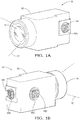
- Fig. 1 illustrates a non-limiting example of a multiple imager camera, hereafter referred to as the camera 10.
- the camera 10 is configured so that a variety of imagers (e.g. 16A, 16B, 16C) such as a visible light-imager, an infrared-light imager, and a low-resolution high-speed imager can capture images from a field of view 12 through a shared lens assembly, hereafter referred to as the lens 14.
- the lens 14 By arranging the plurality of imagers 16A, 16B, 16C to share the lens 14, costs can be reduced since each imager does not need a separate lens, and the overall size of a system that detects images at different wavelengths or at different resolutions can be reduced.
- the camera 10 described herein includes a means to readily align the various imagers with the image from the lens 14 and thereby avoid miss-matched images that my cause reduced clarity when the combined images are viewed by a person.
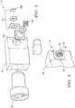
- Fig. 2 further illustrates a non-limiting example of an exploded view of the camera 10.
- the camera includes a frame or a block 20 configured to, among other things, direct the image from the lens 14 to a plurality of imagers 16A, 16B, 16C that are located proximate to a plurality of apertures 22A, 22B, 22C defined by the block 20. While the non-limiting example described herein shows three imagers, cameras with two imagers or more than three imagers are contemplated.
- Fig. 3 shows a non-limiting generic example of an imager 16 which could be any of the plurality of imagers 16A, 16B, 16C.
- the imager 16 is configured to receive the image from the lens 14 through an aperture 22 which could be any of the plurality of apertures 22A, 22B, 22C.
- the aperture 22 is sized such that the imager 16 can be moved relative to the aperture 22 sufficiently to align the imager 16 with the image from the lens 14 and thereby compensate for any expected part-to-part variability of the various parts that make up the camera 10.
- the camera 10 includes an alignment apparatus 24 interposed between the block 20 and the imager 16 proximate to the aperture 22.
- the alignment apparatus 24 is advantageously configured to allow for six degrees of freedom to align the imager 16 with the image.
- the six degrees of freedom include movement along three axis (e.g. x, y, z) and movement around those three axis (e.g. pitch, yaw, roll)
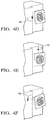
- Figs. 4A, 4B, 4C , 4D, 4E, and 4F illustrate each of the six degrees of freedom or adjustment which include adjustment along a x-axis 41, a y-axis 42, and a z-axis 43 of the aperture 22, and adjustment about a pitch-axis 44, a yaw-axis 45, and a roll-axis 46 of the aperture 22.
- the alignment apparatus 24 is further configured to fixedly couple the imager 16 to the block 20 after the imager 16 is aligned with the image.
- each imager 16 is locked in place so that it does not become miss-aligned after the alignment process has been completed. While the examples illustrated herein all suggest that each imager has a corresponding alignment apparatus, it is contemplated that one of the imagers (e.g. the imager 16B) could be attached or coupled to the block 20 in a non-adjustable manner, and the other imagers (e.g. the imager 16A and/or the imager 16B) could be adjusted relative to the fixed in place imager. However, in order to keep the adjustment process as flexible as possible, it is preferred that each imager is coupled to an adjustment means.
- the imager 16B could be attached or coupled to the block 20 in a non-adjustable manner, and the other imagers (e.g. the imager 16A and/or the imager 16B) could be adjusted relative to the fixed in place imager.
- each imager is coupled to an adjustment means.
- the camera 10 in order to distribute or direct the image from the lens 14 toward the plurality of apertures 22A, 22B, 22C, the camera 10 is equipped with a beam splitter 26 configured to direct the image to the plurality of apertures 22A, 22B, 22C.
- the definition of the beam splitter 26 includes any means or devices suitable to direct an image from the lens 14 in multiple directions such as toward the plurality of apertures 22A, 22B, and 22C.
- the beam splitter may include one or more half-silvered mirrors as will be recognized by those in the art.
- the beam splitter 26 may incorporate one or more electrochromic mirrors that can be operated between a fully reflective state and a fully transmissive state, as will be recognized by those in the art.
- the non-limiting example of the alignment apparatus 24 includes an outer ring 28 coupled to the block 20.
- the outer ring 28 is configured to allow for adjustment of the location of the imager 16 along the x-axis 41 ( Fig. 4A ) and the y-axis 42 ( Fig. 4B ).
- the location of the outer ring 28 may be secured or fixed by, for example, curing an adhesive and/or heat staking.
- an ultra-violet (UV) light curing initiated adhesive may be applied between the outer ring 28 and the block 20 prior to placing the outer ring 28 against the block 20.
- UV ultra-violet
- a UV light source may be used to cure the adhesive and thereby secure the outer ring 28 to the block 20.
- the adhesive may be a hot-melt type adhesive that hardens as it cools.
- the outer ring 28 may be held in place against the block 20 before the adhesive cures by spring loaded fingers (not shown) or some other fixture as will be recognized by those in the art.
- the non-limiting example of the alignment apparatus 24 shown in Fig. 3 and elsewhere also includes a hemispherical ring 30 coupled to the outer ring 28.
- the hemispherical ring 30 is configured to allow for adjustment of the location of the imager 16 along the z-axis 43 ( Fig. 4C ) and the pitch-axis 44 ( Fig. 4D ), the yaw-axis 45 ( Fig. 4E ), and the roll-axis 46 ( Fig. 4F ).
- an ultra-violet (UV) light curing initiated adhesive may be applied between the hemispherical ring 30 and the outer ring 28 prior to inserting the outer ring 28 against the block 20.
- UV ultra-violet
- a UV light source may be used to cure the adhesive and thereby secure the hemispherical ring 30 to the outer ring 28.
- the interface between the hemispherical ring 30 and the outer ring 28 is an interference type or friction type fit so that tooling used to position the imager 16 during the alignment process can release the imager once the alignment is complete.
- Fig. 5 illustrates a non-limiting example of a tool 32 useful to position the imager 16 relative to the block 20 in order to align the imager 16 with the image from the lens 14.
- the imager is attached to a circuit board 34 that is electrically connected to a connector 36 so that images captured by the imager 16 can be monitored during the alignment process.
- the tool 32 may be attached to a robot arm or other position control apparatus effective to position or align the imager 16 with the image.
- the hemispherical ring 30 is fixedly attached to the imager 16 before the imager 16 is aligned with the image.
- the outer ring 28 is not shown in Fig. 5 , but it is contemplated that the outer ring 28 could be placed against the block 20 prior to bringing the imager 16 toward the block 20, or the outer ring 28 could be placed over the hemispherical ring 30 before bringing the imager 16 toward the block 20. In either case, it is preferable that the outer ring 28 is fixedly attached to the block 20 after the imager 16 is aligned with the image. Similarly, it is preferable that the hemispherical ring 30 is fixedly attached to the outer ring 28 after the imager 16 is aligned with the image.
- the alignment process may include orienting the camera 10 so the field of view 12 is directed to a known object (not shown) has predetermined targets useful to determine the alignment of the imager 16 with the image of the object.
- the object may be a wall with various targets painted on the wall so that a controller (not shown) connected to the connector 36 is able to determine the relative alignment of the imager 16.
- a laser may be used to project a beam of light upon one or more pixels of each imager in order to determine the relative alignment of each imager.
- Fig. 6 illustrates a non-limiting example of the alignment apparatus 24 that consists essentially of an arrangement of an adhesive 38 configured to allow the imager 16 to be aligned with the image from the lens 14 when the adhesive 38 is in an uncured state (i.e. semi-liquid or gel-like state), and fixedly attach the imager 16 to the block 20 when the adhesive 38 is in a cured state (i.e. solid or firm state).
- the advantage of this configuration is that it avoids having to provide the outer ring 28 and the hemispherical ring 30.
- a disadvantage is that the imager must be held in place while the adhesive cures.
- the hemispherical ring 30 has an interference type fit to the outer ring 28, that interference will allow the tool 32 to release the tool's grip on the imager assembly and the alignment will not be lost while waiting for any adhesive to cure.
- a multiple imager camera (the camera 10) is provided.
- the camera 10 advantageously includes an alignment apparatus 24 that allows for various imagers (16A, 16B, 16C) to be aligned with an image passing through a shared lens (the lens 14).
- the camera is sometime referred to as a multi-core camera (MCC).
- MCC multi-core camera
- the MCC described herein can be made highly compact, with multiple functions, and able to operate at visible and infra-red wavelengths.
- the cores or imagers can be used for imaging or non-image sensing (e.g. rain or light sensing).
- the configuration also provides for precise focusing of the imagers to the lens.
- the independent alignment provides for the ability to focus the imagers to the lens independently, thereby allowing for variations in the back focal length of the lens 14 due to variations in wavelength, field of view, and/or imager field (size).
Landscapes
- Engineering & Computer Science (AREA)
- Multimedia (AREA)
- Signal Processing (AREA)
- Human Computer Interaction (AREA)
- Studio Devices (AREA)
Claims (4)
- Kamera mit mehreren Bildgebern (10), die aufweist:einen Block (20), der konfiguriert ist zum Lenken eines Bilds an eine Vielzahl von Bildgebern (16A, 16B, 16C), die in der Nähe einer Vielzahl von Öffnungen (22A, 22B, 22C) angeordnet sind, die durch den Block (20) definiert sind;einen Strahlteiler, der konfiguriert ist zum Lenken des Bilds an die Vielzahl von Öffnungen (22A, 22B, 22C);wobei die Vielzahl von Bildgebern (16A, 16B, 16C) konfiguriert ist zum Empfangen des Bilds durch die Vielzahl von Öffnungen (22A, 22B, 22C); und wobei jede Öffnung der Vielzahl von Öffnungen (22A, 22B, 22C) derart dimensioniert ist, dass jeder Bildgeber der Vielzahl von Bildgebern (16A, 16B, 16C) relativ zu seiner entsprechenden Öffnung (22A, 22B, 22C) bewegt werden kann; undeine Vielzahl von Ausrichtungsvorrichtungen (24), wobei jeder Bildgeber (16A, 16B, 16C) eine entsprechende Ausrichtungsvorrichtung (24) hat; undwobei jede Ausrichtungsvorrichtung (24) der Vielzahl von Ausrichtungsvorrichtungen (24) zwischen dem Block (20) und den Bildgebern (16A, 16B, 16C) angeordnet ist, wobei jede Ausrichtungsvorrichtung (24) konfiguriert ist, um sechs Freiheitsgrade zum Ausrichten jedes Bildgebers (16) mit dem Bild zu ermöglichen, wobei die sechs Freiheitsgrade eine Anpassung entlang einer x-Achse (41), einer y-Achse (42) und einer z-Achse (43) der Öffnungen (22A, 22B, 22C) und eine Anpassung um eine Nickachse (44), eine Gierachse (45) und eine Rollachse (46) der Öffnungen (22A, 22B, 22C) umfassen, wobei jede Ausrichtungsvorrichtung (24) weiter konfiguriert ist zum festen Koppeln der Vielzahl von Bildgebern (16A, 16B, 16C) mit dem Block (20), nachdem die Vielzahl von Bildgebern (16A, 16B, 16C) mit dem Bild ausgerichtet ist,dadurch gekennzeichnet, dassjede Ausrichtungsvorrichtung (24) umfassteinen äußeren Ring (28), der mit dem Block (20) gekoppelt und konfiguriert ist, um eine Anpassung entlang der x-Achse (41) und der y-Achse (42) zu ermöglichen; undeinen halbkugelförmigen Ring (30), der mit dem äußeren Ring (28) gekoppelt und konfiguriert ist, um eine Anpassung entlang der z-Achse (43) und um die Nickachse (44), die Gierachse (45) und die Rollachse (46) zu ermöglichen, undwobei jeder halbkugelförmige Ring (30) fest an jedem Bildgeber (16A, 16B, 16C) angebracht wird, bevor jeder Bildgeber (16A, 16B, 16C) mit dem Bild ausgerichtet ist.
- Die Kamera (10) gemäß Anspruch 1, wobei der äußere Ring (28) fest an dem Block (20) angebracht wird, nachdem der Bildgeber (16) mit dem Bild ausgerichtet ist.
- Die Kamera (10) gemäß Anspruch 1, wobei der halbkugelförmige Ring (30) fest an dem äußeren Ring (28) angebracht wird, nachdem der Bildgeber (16) mit dem Bild ausgerichtet ist.
- Die Kamera (10) gemäß einem der Ansprüche 1 bis 3, wobei die Ausrichtungsvorrichtung (24) umfasst
ein Klebemittel (38), das konfiguriert ist, um zu ermöglichen, dass der Bildgeber (16) mit dem Bild ausgerichtet wird, wenn das Klebemittel (38) in einem ungehärteten Zustand ist, und um den Bildgeber (16) fest an dem Block (20) zu befestigen, wenn das Klebemittel (38) in einem ausgehärteten Zustand ist.
Applications Claiming Priority (1)
| Application Number | Priority Date | Filing Date | Title |
|---|---|---|---|
| US14/472,910 US9621874B2 (en) | 2014-08-29 | 2014-08-29 | Multiple imager camera |
Publications (2)
| Publication Number | Publication Date |
|---|---|
| EP2991333A1 EP2991333A1 (de) | 2016-03-02 |
| EP2991333B1 true EP2991333B1 (de) | 2018-10-17 |
Family
ID=53785484
Family Applications (1)
| Application Number | Title | Priority Date | Filing Date |
|---|---|---|---|
| EP15178777.7A Active EP2991333B1 (de) | 2014-08-29 | 2015-07-29 | Kamera mit mehreren bildgebern |
Country Status (3)
| Country | Link |
|---|---|
| US (1) | US9621874B2 (de) |
| EP (1) | EP2991333B1 (de) |
| CN (1) | CN106210458B (de) |
Families Citing this family (3)
| Publication number | Priority date | Publication date | Assignee | Title |
|---|---|---|---|---|
| EP3720739B1 (de) * | 2017-12-04 | 2025-01-15 | Gentex Corporation | Systeme und verfahren zur einstellung von fahrzeuguntersystemen basierend auf der überwachung von fahrzeuginsassen |
| USD995601S1 (en) * | 2018-06-05 | 2023-08-15 | Huddly As | Smart camera |
| US12457393B2 (en) * | 2023-07-19 | 2025-10-28 | Elbit Systems Of America, Llc | Image intensified and color sensor camera |
Family Cites Families (11)
| Publication number | Priority date | Publication date | Assignee | Title |
|---|---|---|---|---|
| US4591901A (en) | 1984-03-30 | 1986-05-27 | Rca Corporation | Television camera with solid-state imagers mounted to a prism |
| US5805218A (en) * | 1995-06-20 | 1998-09-08 | Matsushita Electric Industrial Co., Ltd. | Method for adjusting a position of a solid-state image detector in a given image-forming optical system |
| JP2005117253A (ja) | 2003-10-06 | 2005-04-28 | Tamron Co Ltd | 撮像装置 |
| DE112004002901B4 (de) * | 2004-06-29 | 2016-05-19 | Takami Hasegawa | Abbildungsvorrichtung unter Verwendung eines Festkörper-Bildaufnahmeelements |
| CN101546090B (zh) * | 2008-03-25 | 2011-09-28 | 鸿富锦精密工业(深圳)有限公司 | 成像装置 |
| CN102016709B (zh) | 2008-04-30 | 2014-04-09 | 日本电产三协株式会社 | 带抖动修正功能的光学单元及摄影用光学装置 |
| US8675077B2 (en) * | 2008-07-23 | 2014-03-18 | Flir Systems, Inc. | Alignment metrology and resolution measurement system for imaging arrays |
| CN101487989B (zh) * | 2009-02-27 | 2010-12-29 | 上海微电子装备有限公司 | 六自由度精密定位平台 |
| CN102636140B (zh) * | 2012-04-12 | 2014-07-30 | 重庆大学 | 测量空间六自由度运动的伸缩拉杆式并联装置 |
| CN203300945U (zh) * | 2013-05-02 | 2013-11-20 | 中国科学院光电研究院 | 六自由度调节机构 |
| CN103269009B (zh) * | 2013-05-02 | 2015-10-21 | 中国科学院光电研究院 | 激光器放电腔的六自由度调节机构 |
-
2014
- 2014-08-29 US US14/472,910 patent/US9621874B2/en active Active
-
2015
- 2015-07-10 CN CN201510404656.4A patent/CN106210458B/zh active Active
- 2015-07-29 EP EP15178777.7A patent/EP2991333B1/de active Active
Non-Patent Citations (1)
| Title |
|---|
| None * |
Also Published As
| Publication number | Publication date |
|---|---|
| EP2991333A1 (de) | 2016-03-02 |
| US20160065940A1 (en) | 2016-03-03 |
| CN106210458B (zh) | 2020-09-15 |
| CN106210458A (zh) | 2016-12-07 |
| US9621874B2 (en) | 2017-04-11 |
Similar Documents
| Publication | Publication Date | Title |
|---|---|---|
| US11897398B2 (en) | Vehicular camera with thermally conductive material disposed between and contacting stacked PCBS | |
| US11972597B2 (en) | Vehicular driver monitoring system with camera view optimization | |
| US12271049B2 (en) | Vehicular camera with adhesive disposed between non-axially opposed surfaces of the lens barrel and PCB structure | |
| US11623559B2 (en) | Vehicular forward viewing image capture system | |
| JP4667430B2 (ja) | 車載用カメラ | |
| US10875403B2 (en) | Vehicle vision system with enhanced night vision | |
| US20170280034A1 (en) | Vehicle vision system camera with enhanced imager and lens assembly | |
| JP6441360B2 (ja) | カメラシステムによって取得された画像を車両のバックミラー組立品に表示するための表示システム | |
| US20200057149A1 (en) | Optical sensor and electronic device | |
| US10023118B2 (en) | Vehicle vision system with thermal sensor | |
| US9621874B2 (en) | Multiple imager camera | |
| WO2019012081A1 (en) | VISION SYSTEM AND VISION METHOD FOR A VEHICLE | |
| US7188014B1 (en) | Assistant monitor apparatus and the method of controlling the same | |
| US10440249B2 (en) | Vehicle vision system camera with semi-reflective and semi-transmissive element | |
| EP3428678B1 (de) | Sichtsystem und -verfahren für ein fahrzeug | |
| US12627872B2 (en) | Vehicular camera assembly with thermally conductive adhesive interface | |
| US12258025B2 (en) | Vehicular driver monitoring system with event camera | |
| CZ309533B6 (cs) | Komunikační zařízení motorového vozidla, osvětlovací zařízení motorového vozidla pro komunikační zařízení motorového vozidla a způsob car2car nebo car2X komunikace motorového vozidla | |
| WO2017169087A1 (ja) | 電子ミラーの電気回路 | |
| KR102457275B1 (ko) | 투명 필라 장치 | |
| JP2020162021A (ja) | 多方向同時モニタリング装置 | |
| EP3839553B1 (de) | Lidar-bildgebungsvorrichtung für ein kraftfahrzeug | |
| EP3346693B1 (de) | Abbildungsvorrichtung für ein kraftfahrzeug und verfahren zur montage einer abbildungsvorrichtung in einem kraftfahrzeug |
Legal Events
| Date | Code | Title | Description |
|---|---|---|---|
| PUAI | Public reference made under article 153(3) epc to a published international application that has entered the european phase |
Free format text: ORIGINAL CODE: 0009012 |
|
| AK | Designated contracting states |
Kind code of ref document: A1 Designated state(s): AL AT BE BG CH CY CZ DE DK EE ES FI FR GB GR HR HU IE IS IT LI LT LU LV MC MK MT NL NO PL PT RO RS SE SI SK SM TR |
|
| AX | Request for extension of the european patent |
Extension state: BA ME |
|
| 17P | Request for examination filed |
Effective date: 20160902 |
|
| RBV | Designated contracting states (corrected) |
Designated state(s): AL AT BE BG CH CY CZ DE DK EE ES FI FR GB GR HR HU IE IS IT LI LT LU LV MC MK MT NL NO PL PT RO RS SE SI SK SM TR |
|
| STAA | Information on the status of an ep patent application or granted ep patent |
Free format text: STATUS: EXAMINATION IS IN PROGRESS |
|
| 17Q | First examination report despatched |
Effective date: 20170102 |
|
| GRAP | Despatch of communication of intention to grant a patent |
Free format text: ORIGINAL CODE: EPIDOSNIGR1 |
|
| STAA | Information on the status of an ep patent application or granted ep patent |
Free format text: STATUS: GRANT OF PATENT IS INTENDED |
|
| INTG | Intention to grant announced |
Effective date: 20180508 |
|
| RIN1 | Information on inventor provided before grant (corrected) |
Inventor name: TAYLOR, RONALD M. Inventor name: DEGENKOLB, THOMAS A. Inventor name: MURPHY, MORGAN D. Inventor name: EVERLY, WARD K. Inventor name: LOW, YEW KWANG Inventor name: YEO, KOK WEE Inventor name: LOONG, DANIEL LEONG WOON |
|
| GRAS | Grant fee paid |
Free format text: ORIGINAL CODE: EPIDOSNIGR3 |
|
| GRAA | (expected) grant |
Free format text: ORIGINAL CODE: 0009210 |
|
| STAA | Information on the status of an ep patent application or granted ep patent |
Free format text: STATUS: THE PATENT HAS BEEN GRANTED |
|
| AK | Designated contracting states |
Kind code of ref document: B1 Designated state(s): AL AT BE BG CH CY CZ DE DK EE ES FI FR GB GR HR HU IE IS IT LI LT LU LV MC MK MT NL NO PL PT RO RS SE SI SK SM TR |
|
| REG | Reference to a national code |
Ref country code: GB Ref legal event code: FG4D |
|
| REG | Reference to a national code |
Ref country code: CH Ref legal event code: EP |
|
| REG | Reference to a national code |
Ref country code: IE Ref legal event code: FG4D |
|
| REG | Reference to a national code |
Ref country code: DE Ref legal event code: R096 Ref document number: 602015018183 Country of ref document: DE Ref country code: AT Ref legal event code: REF Ref document number: 1055402 Country of ref document: AT Kind code of ref document: T Effective date: 20181115 |
|
| REG | Reference to a national code |
Ref country code: DE Ref legal event code: R081 Ref document number: 602015018183 Country of ref document: DE Owner name: APTIV TECHNOLOGIES LIMITED, BB Free format text: FORMER OWNER: DELPHI TECHNOLOGIES, INC., TROY, MICH., US |
|
| REG | Reference to a national code |
Ref country code: NL Ref legal event code: MP Effective date: 20181017 |
|
| REG | Reference to a national code |
Ref country code: LT Ref legal event code: MG4D |
|
| REG | Reference to a national code |
Ref country code: AT Ref legal event code: MK05 Ref document number: 1055402 Country of ref document: AT Kind code of ref document: T Effective date: 20181017 |
|
| PG25 | Lapsed in a contracting state [announced via postgrant information from national office to epo] |
Ref country code: NL Free format text: LAPSE BECAUSE OF FAILURE TO SUBMIT A TRANSLATION OF THE DESCRIPTION OR TO PAY THE FEE WITHIN THE PRESCRIBED TIME-LIMIT Effective date: 20181017 |
|
| PG25 | Lapsed in a contracting state [announced via postgrant information from national office to epo] |
Ref country code: FI Free format text: LAPSE BECAUSE OF FAILURE TO SUBMIT A TRANSLATION OF THE DESCRIPTION OR TO PAY THE FEE WITHIN THE PRESCRIBED TIME-LIMIT Effective date: 20181017 Ref country code: LV Free format text: LAPSE BECAUSE OF FAILURE TO SUBMIT A TRANSLATION OF THE DESCRIPTION OR TO PAY THE FEE WITHIN THE PRESCRIBED TIME-LIMIT Effective date: 20181017 Ref country code: AT Free format text: LAPSE BECAUSE OF FAILURE TO SUBMIT A TRANSLATION OF THE DESCRIPTION OR TO PAY THE FEE WITHIN THE PRESCRIBED TIME-LIMIT Effective date: 20181017 Ref country code: LT Free format text: LAPSE BECAUSE OF FAILURE TO SUBMIT A TRANSLATION OF THE DESCRIPTION OR TO PAY THE FEE WITHIN THE PRESCRIBED TIME-LIMIT Effective date: 20181017 Ref country code: HR Free format text: LAPSE BECAUSE OF FAILURE TO SUBMIT A TRANSLATION OF THE DESCRIPTION OR TO PAY THE FEE WITHIN THE PRESCRIBED TIME-LIMIT Effective date: 20181017 Ref country code: PL Free format text: LAPSE BECAUSE OF FAILURE TO SUBMIT A TRANSLATION OF THE DESCRIPTION OR TO PAY THE FEE WITHIN THE PRESCRIBED TIME-LIMIT Effective date: 20181017 Ref country code: BG Free format text: LAPSE BECAUSE OF FAILURE TO SUBMIT A TRANSLATION OF THE DESCRIPTION OR TO PAY THE FEE WITHIN THE PRESCRIBED TIME-LIMIT Effective date: 20190117 Ref country code: ES Free format text: LAPSE BECAUSE OF FAILURE TO SUBMIT A TRANSLATION OF THE DESCRIPTION OR TO PAY THE FEE WITHIN THE PRESCRIBED TIME-LIMIT Effective date: 20181017 Ref country code: IS Free format text: LAPSE BECAUSE OF FAILURE TO SUBMIT A TRANSLATION OF THE DESCRIPTION OR TO PAY THE FEE WITHIN THE PRESCRIBED TIME-LIMIT Effective date: 20190217 Ref country code: NO Free format text: LAPSE BECAUSE OF FAILURE TO SUBMIT A TRANSLATION OF THE DESCRIPTION OR TO PAY THE FEE WITHIN THE PRESCRIBED TIME-LIMIT Effective date: 20190117 |
|
| PG25 | Lapsed in a contracting state [announced via postgrant information from national office to epo] |
Ref country code: AL Free format text: LAPSE BECAUSE OF FAILURE TO SUBMIT A TRANSLATION OF THE DESCRIPTION OR TO PAY THE FEE WITHIN THE PRESCRIBED TIME-LIMIT Effective date: 20181017 Ref country code: PT Free format text: LAPSE BECAUSE OF FAILURE TO SUBMIT A TRANSLATION OF THE DESCRIPTION OR TO PAY THE FEE WITHIN THE PRESCRIBED TIME-LIMIT Effective date: 20190217 Ref country code: GR Free format text: LAPSE BECAUSE OF FAILURE TO SUBMIT A TRANSLATION OF THE DESCRIPTION OR TO PAY THE FEE WITHIN THE PRESCRIBED TIME-LIMIT Effective date: 20190118 Ref country code: RS Free format text: LAPSE BECAUSE OF FAILURE TO SUBMIT A TRANSLATION OF THE DESCRIPTION OR TO PAY THE FEE WITHIN THE PRESCRIBED TIME-LIMIT Effective date: 20181017 Ref country code: SE Free format text: LAPSE BECAUSE OF FAILURE TO SUBMIT A TRANSLATION OF THE DESCRIPTION OR TO PAY THE FEE WITHIN THE PRESCRIBED TIME-LIMIT Effective date: 20181017 |
|
| REG | Reference to a national code |
Ref country code: DE Ref legal event code: R097 Ref document number: 602015018183 Country of ref document: DE |
|
| PG25 | Lapsed in a contracting state [announced via postgrant information from national office to epo] |
Ref country code: CZ Free format text: LAPSE BECAUSE OF FAILURE TO SUBMIT A TRANSLATION OF THE DESCRIPTION OR TO PAY THE FEE WITHIN THE PRESCRIBED TIME-LIMIT Effective date: 20181017 Ref country code: IT Free format text: LAPSE BECAUSE OF FAILURE TO SUBMIT A TRANSLATION OF THE DESCRIPTION OR TO PAY THE FEE WITHIN THE PRESCRIBED TIME-LIMIT Effective date: 20181017 Ref country code: DK Free format text: LAPSE BECAUSE OF FAILURE TO SUBMIT A TRANSLATION OF THE DESCRIPTION OR TO PAY THE FEE WITHIN THE PRESCRIBED TIME-LIMIT Effective date: 20181017 |
|
| PLBE | No opposition filed within time limit |
Free format text: ORIGINAL CODE: 0009261 |
|
| STAA | Information on the status of an ep patent application or granted ep patent |
Free format text: STATUS: NO OPPOSITION FILED WITHIN TIME LIMIT |
|
| PG25 | Lapsed in a contracting state [announced via postgrant information from national office to epo] |
Ref country code: EE Free format text: LAPSE BECAUSE OF FAILURE TO SUBMIT A TRANSLATION OF THE DESCRIPTION OR TO PAY THE FEE WITHIN THE PRESCRIBED TIME-LIMIT Effective date: 20181017 Ref country code: SM Free format text: LAPSE BECAUSE OF FAILURE TO SUBMIT A TRANSLATION OF THE DESCRIPTION OR TO PAY THE FEE WITHIN THE PRESCRIBED TIME-LIMIT Effective date: 20181017 Ref country code: SK Free format text: LAPSE BECAUSE OF FAILURE TO SUBMIT A TRANSLATION OF THE DESCRIPTION OR TO PAY THE FEE WITHIN THE PRESCRIBED TIME-LIMIT Effective date: 20181017 Ref country code: RO Free format text: LAPSE BECAUSE OF FAILURE TO SUBMIT A TRANSLATION OF THE DESCRIPTION OR TO PAY THE FEE WITHIN THE PRESCRIBED TIME-LIMIT Effective date: 20181017 |
|
| 26N | No opposition filed |
Effective date: 20190718 |
|
| PG25 | Lapsed in a contracting state [announced via postgrant information from national office to epo] |
Ref country code: SI Free format text: LAPSE BECAUSE OF FAILURE TO SUBMIT A TRANSLATION OF THE DESCRIPTION OR TO PAY THE FEE WITHIN THE PRESCRIBED TIME-LIMIT Effective date: 20181017 |
|
| PG25 | Lapsed in a contracting state [announced via postgrant information from national office to epo] |
Ref country code: MC Free format text: LAPSE BECAUSE OF FAILURE TO SUBMIT A TRANSLATION OF THE DESCRIPTION OR TO PAY THE FEE WITHIN THE PRESCRIBED TIME-LIMIT Effective date: 20181017 |
|
| REG | Reference to a national code |
Ref country code: CH Ref legal event code: PL |
|
| PG25 | Lapsed in a contracting state [announced via postgrant information from national office to epo] |
Ref country code: TR Free format text: LAPSE BECAUSE OF FAILURE TO SUBMIT A TRANSLATION OF THE DESCRIPTION OR TO PAY THE FEE WITHIN THE PRESCRIBED TIME-LIMIT Effective date: 20181017 |
|
| REG | Reference to a national code |
Ref country code: BE Ref legal event code: MM Effective date: 20190731 |
|
| PG25 | Lapsed in a contracting state [announced via postgrant information from national office to epo] |
Ref country code: BE Free format text: LAPSE BECAUSE OF NON-PAYMENT OF DUE FEES Effective date: 20190731 Ref country code: CH Free format text: LAPSE BECAUSE OF NON-PAYMENT OF DUE FEES Effective date: 20190731 Ref country code: LU Free format text: LAPSE BECAUSE OF NON-PAYMENT OF DUE FEES Effective date: 20190729 Ref country code: LI Free format text: LAPSE BECAUSE OF NON-PAYMENT OF DUE FEES Effective date: 20190731 |
|
| PG25 | Lapsed in a contracting state [announced via postgrant information from national office to epo] |
Ref country code: IE Free format text: LAPSE BECAUSE OF NON-PAYMENT OF DUE FEES Effective date: 20190729 |
|
| PG25 | Lapsed in a contracting state [announced via postgrant information from national office to epo] |
Ref country code: CY Free format text: LAPSE BECAUSE OF FAILURE TO SUBMIT A TRANSLATION OF THE DESCRIPTION OR TO PAY THE FEE WITHIN THE PRESCRIBED TIME-LIMIT Effective date: 20181017 |
|
| PG25 | Lapsed in a contracting state [announced via postgrant information from national office to epo] |
Ref country code: MT Free format text: LAPSE BECAUSE OF FAILURE TO SUBMIT A TRANSLATION OF THE DESCRIPTION OR TO PAY THE FEE WITHIN THE PRESCRIBED TIME-LIMIT Effective date: 20181017 Ref country code: HU Free format text: LAPSE BECAUSE OF FAILURE TO SUBMIT A TRANSLATION OF THE DESCRIPTION OR TO PAY THE FEE WITHIN THE PRESCRIBED TIME-LIMIT; INVALID AB INITIO Effective date: 20150729 |
|
| PG25 | Lapsed in a contracting state [announced via postgrant information from national office to epo] |
Ref country code: MK Free format text: LAPSE BECAUSE OF FAILURE TO SUBMIT A TRANSLATION OF THE DESCRIPTION OR TO PAY THE FEE WITHIN THE PRESCRIBED TIME-LIMIT Effective date: 20181017 |
|
| REG | Reference to a national code |
Ref country code: DE Ref legal event code: R079 Ref document number: 602015018183 Country of ref document: DE Free format text: PREVIOUS MAIN CLASS: H04N0005225000 Ipc: H04N0023000000 |
|
| P01 | Opt-out of the competence of the unified patent court (upc) registered |
Effective date: 20230425 |
|
| REG | Reference to a national code |
Ref country code: DE Ref legal event code: R081 Ref document number: 602015018183 Country of ref document: DE Owner name: APTIV TECHNOLOGIES AG, CH Free format text: FORMER OWNER: APTIV TECHNOLOGIES LIMITED, ST. MICHAEL, BB |
|
| PGFP | Annual fee paid to national office [announced via postgrant information from national office to epo] |
Ref country code: DE Payment date: 20250618 Year of fee payment: 11 |
|
| PGFP | Annual fee paid to national office [announced via postgrant information from national office to epo] |
Ref country code: GB Payment date: 20250703 Year of fee payment: 11 |
|
| PGFP | Annual fee paid to national office [announced via postgrant information from national office to epo] |
Ref country code: FR Payment date: 20250703 Year of fee payment: 11 |