EP2991278A1 - Procédé et système pour gérer le trafic sur un réseau - Google Patents
Procédé et système pour gérer le trafic sur un réseau Download PDFInfo
- Publication number
- EP2991278A1 EP2991278A1 EP14306326.1A EP14306326A EP2991278A1 EP 2991278 A1 EP2991278 A1 EP 2991278A1 EP 14306326 A EP14306326 A EP 14306326A EP 2991278 A1 EP2991278 A1 EP 2991278A1
- Authority
- EP
- European Patent Office
- Prior art keywords
- gateway
- private
- server
- connection
- user equipment
- Prior art date
- Legal status (The legal status is an assumption and is not a legal conclusion. Google has not performed a legal analysis and makes no representation as to the accuracy of the status listed.)
- Granted
Links
- 238000000034 method Methods 0.000 title claims abstract description 26
- 238000012544 monitoring process Methods 0.000 claims abstract description 18
- 230000006855 networking Effects 0.000 description 6
- 238000012913 prioritisation Methods 0.000 description 3
- 238000012360 testing method Methods 0.000 description 3
- 238000013507 mapping Methods 0.000 description 2
- 230000001360 synchronised effect Effects 0.000 description 2
- 238000004891 communication Methods 0.000 description 1
- 238000013500 data storage Methods 0.000 description 1
- 239000003365 glass fiber Substances 0.000 description 1
- 238000013519 translation Methods 0.000 description 1
Images


Classifications
-
- H—ELECTRICITY
- H04—ELECTRIC COMMUNICATION TECHNIQUE
- H04W—WIRELESS COMMUNICATION NETWORKS
- H04W76/00—Connection management
- H04W76/10—Connection setup
- H04W76/19—Connection re-establishment
-
- H—ELECTRICITY
- H04—ELECTRIC COMMUNICATION TECHNIQUE
- H04L—TRANSMISSION OF DIGITAL INFORMATION, e.g. TELEGRAPHIC COMMUNICATION
- H04L12/00—Data switching networks
- H04L12/64—Hybrid switching systems
- H04L12/6418—Hybrid transport
-
- H—ELECTRICITY
- H04—ELECTRIC COMMUNICATION TECHNIQUE
- H04L—TRANSMISSION OF DIGITAL INFORMATION, e.g. TELEGRAPHIC COMMUNICATION
- H04L12/00—Data switching networks
- H04L12/28—Data switching networks characterised by path configuration, e.g. LAN [Local Area Networks] or WAN [Wide Area Networks]
- H04L12/2803—Home automation networks
- H04L12/283—Processing of data at an internetworking point of a home automation network
- H04L12/2834—Switching of information between an external network and a home network
-
- H—ELECTRICITY
- H04—ELECTRIC COMMUNICATION TECHNIQUE
- H04W—WIRELESS COMMUNICATION NETWORKS
- H04W76/00—Connection management
- H04W76/10—Connection setup
-
- H—ELECTRICITY
- H04—ELECTRIC COMMUNICATION TECHNIQUE
- H04W—WIRELESS COMMUNICATION NETWORKS
- H04W88/00—Devices specially adapted for wireless communication networks, e.g. terminals, base stations or access point devices
- H04W88/16—Gateway arrangements
Definitions
- the present invention relates to the field of networking.
- it relates to a method and system for managing network traffic between one or more user equipment devices in a private network and a server outside the private network via a private gateway, a server gateway and a connection therebetween.
- Private networks are usually connected to a wide area network, which is typically a server in the World Wide Web, via a private router, also known as a private gateway, which sends and routes data packets within and between networks.
- a control plane contains routing protocols to discover the overall network topology and draw a routing table, which defines what to do with incoming data packets.
- the data plane forwards data packets based on the routing and forwarding information of the control plane protocols. Together, they route the network traffic between a private network and another network.
- private gateways commonly have a Dynamic Host Configuration Protocol (DHCP) server, which assigns IP addresses to the user equipment devices in the private network, which simplifies the configuration network configuration, and contain a Network Address Translation (NAT) function, which allows connecting multiple devices to the network using only one IP address.
- DHCP Dynamic Host Configuration Protocol
- NAT Network Address Translation
- modern private gateways comprise functions for security, logging, network storage, media services, smart home control and often contain a firewall.
- Private gateways can be intelligent and complex devices and a wide variety of different models are available on the market. Both this diversity and complexity can make the implementation of new service features difficult (and expensive). Furthermore, service providers tend to reduce their operational and capital expenditure and increase their revenues by offering more services. For service providers, it can be more attractive to virtualize private network services, i.e. to run them elsewhere, for example at a server somewhere in the World Wide Web. Such virtualization has multiple advantages. The locally installed equipment can be much simpler and it allows updating services without locally updating networking equipment. The drawback of moving functionality to the server, however, is that when the private gateway and server gateway get disconnected, the main services are lost as well. Currently, the functionality is located at the private gateway and all services are still available in the private network, even if the connection to the server is down. To prevent loss of services it has been proposed to provide the private gateway with a fall-back connection to the Internet, such as Wi-Fi or GSM (3G/4G) in case the main connection to the Internet, such as by glass fibre or cable, is lost.
- the invention relates to a method as claimed in claim 1. More specifically, according to the invention, there is provided a method for managing network traffic between one or more user equipment devices in a private network and a server outside the private network via a private gateway, a server gateway and a connection therebetween, wherein the server gateway acts as a router performing routing for the private network, and the private gateway acts as a bridge forwarding data traffic between the user equipment devices and the server gateway, comprising the steps of:
- the private gateway which can either be a physical networking device or a virtual function on a server in the World Wide Web, or a combination of both.
- the private network is extended outside the customer premises and service functions such as network mapping and IP address assignment are provided by a control plane located on the server gateway.
- the private gateway located at the private network side is configured to act as a bridge, which means it basically only forwards data to the server gateway and does not provide control plane or complex data plane services. This allows the private gateway architecture to be much simpler and it allows updating services without locally updating networking equipment.
- the server delivers a service to multiple individual private networks, it is easier to update the server than to update each of the individual private networks.
- the drawback of moving functionality to the server is that when the private gateway and server gateway get disconnected, the main services are lost as well.
- One way to overcome this drawback is by switching the private gateway from a bridge operation mode to a minimal service mode, wherein said minimal service mode provides basic service functions, such as IP address assignment for new and timed-out devices, Wi-Fi control, Wi-Fi authentication and quality of service requirement based prioritization.
- the method further comprises synchronizing a register on the private gateway with a register on the server gateway, wherein said registers comprise a configuration value that contains the minimum required information for the private gateway to operate in case of loss of connection between the private gateway and the server gateway. Synchronization provides an up-to-date configuration value, which is required to boot and minimally operate the private gateway in the event the private gateway and the server gateway get disconnected.
- the method further comprises connecting the one or more user equipment devices in the private network to an other user equipment device in the private network after switching to the minimal service mode in the event of loss of connection between the private gateway and the server gateway, wherein said other user equipment device connects to the server through a connection different from the connection between the private gateway and the server gateway, therewith establishing an alternative connection between the private network and the server.
- said other user equipment device connects to the server through a connection different from the connection between the private gateway and the server gateway, therewith establishing an alternative connection between the private network and the server.
- it comprises switching the private gateway from the minimal service mode to a sleep state mode, wherein said sleep state mode includes monitoring the connection between the private network and server.
- the private gateway detects the eventual loss of connection between the private gateway and the server gateway either passively or actively. Passive monitoring is performed by a connection monitor on the private gateway, which only detects if there is data traffic from and to the server. Active monitoring comprises sending test data to a connection monitor responder on the server gateway, wherein said responder responds to the connection monitor on the private gateway if it receives the test data packets.
- the private gateway controls the set-up of the connection between the one or more user equipment devices and the other user equipment device.
- the other user equipment device in the private network acts as a bridge between the private gateway and the server gateway.
- the other user equipment device in the private network acts as a bridge between the one or more user equipment devices and the server gateway.
- the other user equipment device takes over the bridging services from the private gateway. Basically, it becomes the private gateway for the disconnected user equipment devices.
- the server gateway will continue to provide control plane services for the network traffic.
- the other user equipment device in the private network connects wirelessly to the server gateway.
- the method further comprises connecting the one or more user equipment devices in the private network to the private gateway in case of retrieved connection, wherein the private gateway switches from sleep state mode to bridge operation mode and connects to the server gateway, therewith re-establishing the connection between the private network and the server.
- the invention further relates to a system for managing network traffic between one or more user equipment devices in a private network and a server outside the private network via a private gateway, a server gateway and a connection therebetween, wherein the server gateway acts as a router performing routing for the private network, and the private gateway acts as a bridge allowing data traffic between the user equipment devices and the server gateway, wherein said system comprises:
- the system further comprises registers and synchronizing means for synchronizing a register on the private gateway with a register on the server gateway, wherein said registers comprise a configuration value that contains the minimum required information for the private gateway to operate in case of loss of connection between the private gateway and the server gateway. Synchronization provides an up-to-date configuration value, which is required to boot and minimally operate the private gateway in the event the private gateway and the server gateway get disconnected.
- the system further comprises one or more other user equipment devices in the private network and means for connecting the one or more user equipment devices in the private network to the one or more other user equipment devices in the private network after switching to the minimal service mode in the event of loss of connection, wherein said one or more other user equipment devices in the private network are configured to connect to the one or more user equipment devices in the private network and to connect to the server through a connection different from the connection between the private gateway and the server gateway, therewith configured to establish an alternative connection between the private network and the server.
- the embodiment preferably comprises means for switching the private gateway from the minimal service mode to a sleep state mode, wherein said sleep state mode includes monitoring the connection between the private network and server.
- said one or more other user equipment devices in the private network are configured to wirelessly connect to the server gateway.
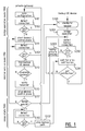
- Figure 1 is a flow chart illustrating the different modes of operation of a private gateway in a method for managing network traffic between one or more user equipment devices in a private network and a server outside the private network via a private gateway, a server gateway and a connection therebetween, wherein the server gateway acts as a router performing routing for the private network, and the private gateway acts as a bridge, indicated by 100, allowing data traffic between the user equipment devices and the server gateway.
- the private gateway acts as a router performing routing for the private network
- the private gateway acts as a bridge, indicated by 100, allowing data traffic between the user equipment devices and the server gateway.
- a register on the private gateway containing a minimal configuration is continuously synchronized with the a register of the server gateway, which step is indicated by S101.
- the private gateway continuously monitors the connection between the private gateway and the server gateway, indicated by S102. If the private gateway and server gateway are actively connected, the private gateway continues to synchronize its configuration register (S101) with that of the server gateway and keeps on monitoring the connection. In the event the connection between the private gateway and the server gateway is lost, the connection monitor, which is part of the private gateway, starts (110) the minimal service mode of the private gateway, which initiates (S111) the minimal control plane on the private gateway. This minimal control plane provides basic service functions, such as IP address assignment for new and timed-out devices, Wi-Fi control, Wi-Fi authentication and quality of service requirement based prioritization. At the same time, the private gateway keeps monitoring (S102) the connection to the server gateway and switches back to normal bridge operation in case the connection is retrieved.
- S101 configuration register
- the private gateway if the connection remains lost, the private gateway starts searching (S112) for back-up user equipment (back-up UE) devices in the private network which can (wirelessly) connect to the server and establish a back-up connection between the private network and the server. If there is no back-up UE device available, the private gateway continues to operate in said minimal service mode. In case there is a back-up UE device available, the private gateway notifies (S113) the waiting (S119) back-up UE device of the take-over of the bridging services from the private gateway. From then on, the back-up UE device acts as a bridge for the user equipment devices which lost connection with the server, wherein said bridge operation is indicated by S200.
- back-up UE back-up user equipment
- the connection monitor After successful take-over of the bridging services from the private gateway, the connection monitor stops the minimal control plane (S111') on the private gateway, the private gateway switches to a sleep state (120), wherein it keeps monitoring (S102) whether there is an active connection between the private gateway and the server gateway, and the back-up device continues to act as a bridge until it gets notified not to do so, for example in case the connection monitor detects retrieved connection between the private gateway and server gateway.
- the back-up device monitors (S202) his connection to the server gateway and alerts (S203) the private gateway in case the back-up device loses connection with the server gateway. In this case, the private gateway switches from sleep state 120 back to the minimal service mode 110.
- the back-up device continues to act as a bridge and waits (S201) for a stop notification from the private gateway in case of retrieved connection between the private gateway and the server gateway Then, the private gateway stops the back-up path (S113') by notifying the back-up UE device of the retrieved connection and by switching back to normal bridge operation.
- Figure 2 schematically illustrates a private network HN connected to a server in the World Wide Web (WWW), according to the prior art.
- Private networks are used for multiple purposes, e.g. for setting up a home network or small business network, and are characterized by their limited geographical coverage.
- One or more user equipment devices UE n can connect to the private network HN via wired or wireless connections when the user equipment devices UE n reside in the geographical area that is covered by the private network HN.
- Figure 2 shows one or more user equipment devices UE n in the private network.
- the private gateway 500 is equipped with means to recognize predetermined user equipment devices and to assign predetermined parameters to the user equipment devices and to manage private services, such as network attached device control and data storage. It allows data traffic and provides data traffic control via respectively its data plane 520 and control plane 510.
- Figure 2 shows a server gateway or server access node 600, which basically acts as a gateway to the server in the WWW.
- the private gateway In prior art private networks, the private gateway must be configured correctly to assign rights and restrictions to the user equipment devices and to implement private services. Recent trends have shown that certain services, such as online document storage, can be easily outsourced to the server. It is an objective of the present invention to relocate routing services, conventionally provided by the control plane and data plane on the private gateway, to the server gateway. This way, the private network is extended outside the customer premises and service functions such as network mapping are provided by a control plane located on the server gateway.
- the private gateway located at the private network side is configured to act as a bridge, which means it basically only forwards data to the server gateway and does not provide control plane services.
- Figure 3 illustrates an embodiment of the invention, wherein one or more user equipment devices UE n in a private network HN are connected through a private gateway 500 and a server gateway 600 to a server in the WWW outside the private network HN.
- routing is substantially performed by the full control plane 610 of the server gateway 600, and the private gateway 500 only operates a slave control plane 540, whereby the private gateway 500 essentially acts as a bridge that forwards data through the data planes 520 and 620 of the private gateway 500 and the server gateway 600 respectively, from the private network HN to the server.
- the configuration register 570 of the private gateway 500 is continuously synchronized (S101) by the configuration synchronizers 560 and 660 of the private gateway 500 and server gateway 600 respectively, with the configuration register 690 of the server gateway 600.
- the connection between the private gateway 500 and the server gateway 600 is continuously monitored by the connection monitor 550, located on the private gateway 500. If the private gateway 500 and server gateway 600 are actively connected, the configuration synchronizers 560 and 660 continue to synchronize the configuration register 570 with the configuration register 690 and the connection monitor 550 keeps on monitoring the connection.
- connection is passively monitored by the connection monitor 550, which entails monitoring traffic that is already on the network.
- the connection is actively monitored (S102) by means of the connection monitor 550 and a connection monitor responder 650 on the server gateway 600, which involves injecting test traffic onto the network and monitoring the flow of that traffic.
- Figure 4 illustrates an embodiment of the invention in the situation that the connection between the private gateway 500 and the server gateway 600 is lost.
- the connection monitor 550 which is part of the private gateway 500, detects that the active link is down and starts the minimal service mode of the private gateway 500, which initiates (S111) the minimal control plane 530 on the private gateway 500.
- the minimal control plane 530 provides basic service functions such as IP address assignment for new and timed-out devices, Wi-Fi control, Wi-Fi authentication and quality of service requirement based prioritization, by means of which communication between the one ore more user equipment devices UE n in the private network HN can continue.
- Figure 5 illustrates another preferred embodiment of the present invention wherein the eventual connection loss is passively detected by the connection monitor 550 on the private gateway 500.
- the private gateway 500 starts searching for another user equipment device in the private network HN, in the Figures 5-7 referred to as back-up user equipment device UE BU , which can (wirelessly) connect to the server in the WWW and re-establish an active connection between the private network HN and the server. If there is no back-up user equipment device UE BU available, the private gateway 500 continues to operate in said minimal service mode.
- the private gateway notifies (S113) the back-up user equipment device UE BU , which takes over bridging services from the private gateway 500, thereby taking over the functionality from 520. From then on, the back-up user equipment device UE BU acts as a bridge between the private gateway 500 and the server gateway 600, or as a second bridge for network traffic between the user equipment devices UE n and the server gateway 600.
- the routing protocols are continued to be provided by the control plane 610 of the server gateway 600.
- the connection monitor 550 stops (S111') the minimal control plane 530 on the private gateway 500 and the back-up user equipment device UE BU continues to act as a bridge until it gets notified not to do so, for example in case the connection monitor 550 detects retrieved connection between the private gateway 500 and server gateway 600. Until then, it waits for a stop notification.
- the private gateway 500 switches to a sleep state, wherein it at least keeps monitoring whether there is an active connection between the private gateway 500 and the server gateway 600.
- connection monitor 550 on the private gateway 500 keeps on monitoring and the back-up user equipment device UE BU continues to act as a bridge connecting the private network HN to the server.
- the private gateway 500 stops the back-up path by notifying the one or more user equipment devices and the back-up user equipment device UE BU of the retrieved connection and by switching back to normal bridge operation.
- Figure 6 illustrates another embodiment of the present invention, wherein the eventual connection loss is actively detected by both the connection monitor 550 on the private gateway 500 and the connection monitor responder 650 on the server gateway 600.
- the private gateway 500 starts searching for a back-up user equipment device UE BU in the private network HN which can (wirelessly) connect to the server in the WWW and establish a back-up connection between the private network HN and the server. If there is no back-up user equipment device UE BU available, the private gateway 500 continues to operate in the minimal service mode.
- the private gateway 500 notifies (S113) the back-up user equipment device UE BU , which takes over all services from the private gateway 500, thereby taking over full functionality from the private gateway 500 and re-establishing the connection between the one or more user equipment devices UE n in the private network HN and the server gateway.
- the routing protocols are provided by the control plane 610 of the server gateway 600.
- the connection monitor 550 stops the minimal control plane 530 on the private gateway 500 and the back-up user equipment device UE BU continues to act as a bridge until it gets notified not to do so, for example in case the connection monitor responder 650 detects retrieved connection between the private gateway 500 and server gateway 600. Until then, the back-up user equipment device UE BU waits for a stop notification. After successful take-over, the private gateway 500 switches to a sleep state, wherein it at least keeps monitoring whether there is an active connection between the private gateway 500 and the server gateway 600.
- connection monitor 550 and the connection monitor responder 650 keep on monitoring and the back-up user equipment device UE BU continues to act as a bridge connecting the private network HN to the server.
- the private gateway 500 stops the back-up path by notifying the one or more user equipment devices and the back-up user equipment device UE BU of the retrieved connection and by switching back to normal bridge operation.
Landscapes
- Engineering & Computer Science (AREA)
- Computer Networks & Wireless Communication (AREA)
- Signal Processing (AREA)
- Automation & Control Theory (AREA)
- Computing Systems (AREA)
- Data Exchanges In Wide-Area Networks (AREA)
- Mobile Radio Communication Systems (AREA)
- Small-Scale Networks (AREA)
Priority Applications (6)
| Application Number | Priority Date | Filing Date | Title |
|---|---|---|---|
| EP14306326.1A EP2991278B1 (fr) | 2014-08-28 | 2014-08-28 | Procédé et système pour gérer le trafic sur un réseau |
| JP2017511738A JP6389956B2 (ja) | 2014-08-28 | 2015-08-24 | ネットワークトラフィックを管理する方法およびシステム |
| PCT/EP2015/069302 WO2016030303A1 (fr) | 2014-08-28 | 2015-08-24 | Procédé et système de gestion de trafic de réseau |
| KR1020177008170A KR101909400B1 (ko) | 2014-08-28 | 2015-08-24 | 네트워크 트래픽을 관리하는 방법 및 시스템 |
| US15/501,993 US10201033B2 (en) | 2014-08-28 | 2015-08-24 | Method and system for managing network traffic |
| CN201580046299.7A CN106797332B (zh) | 2014-08-28 | 2015-08-24 | 用于管理网络流量的方法和系统 |
Applications Claiming Priority (1)
| Application Number | Priority Date | Filing Date | Title |
|---|---|---|---|
| EP14306326.1A EP2991278B1 (fr) | 2014-08-28 | 2014-08-28 | Procédé et système pour gérer le trafic sur un réseau |
Publications (2)
| Publication Number | Publication Date |
|---|---|
| EP2991278A1 true EP2991278A1 (fr) | 2016-03-02 |
| EP2991278B1 EP2991278B1 (fr) | 2019-07-31 |
Family
ID=51542298
Family Applications (1)
| Application Number | Title | Priority Date | Filing Date |
|---|---|---|---|
| EP14306326.1A Active EP2991278B1 (fr) | 2014-08-28 | 2014-08-28 | Procédé et système pour gérer le trafic sur un réseau |
Country Status (6)
| Country | Link |
|---|---|
| US (1) | US10201033B2 (fr) |
| EP (1) | EP2991278B1 (fr) |
| JP (1) | JP6389956B2 (fr) |
| KR (1) | KR101909400B1 (fr) |
| CN (1) | CN106797332B (fr) |
| WO (1) | WO2016030303A1 (fr) |
Families Citing this family (8)
| Publication number | Priority date | Publication date | Assignee | Title |
|---|---|---|---|---|
| US10559177B2 (en) * | 2016-08-04 | 2020-02-11 | Dean Michael Feldman | Area and property monitoring system and method |
| EP3496374A4 (fr) * | 2016-09-30 | 2019-07-17 | Huawei Technologies Co., Ltd. | Procédé et dispositif d'attribution d'adresse ip |
| US10757105B2 (en) * | 2017-06-12 | 2020-08-25 | At&T Intellectual Property I, L.P. | On-demand network security system |
| EP3718255B1 (fr) * | 2017-11-29 | 2023-06-07 | ABB Schweiz AG | Procédé et dispositif de transmission de données dans une sous-station |
| JP7220550B2 (ja) * | 2018-11-12 | 2023-02-10 | 三菱重工業株式会社 | エッジ装置、接続確立システム、接続確立方法及びプログラム |
| CN109756748A (zh) * | 2019-01-30 | 2019-05-14 | 百度在线网络技术(北京)有限公司 | 多媒体专辑的生成方法、装置及计算机设备 |
| CN114531485A (zh) * | 2021-12-28 | 2022-05-24 | 望海康信(北京)科技股份公司 | 数据传输方法、系统及相应设备和存储介质 |
| WO2024071715A1 (fr) * | 2022-09-26 | 2024-04-04 | 삼성전자주식회사 | Dispositif électronique et procédé de réglage de niveau de réseau |
Citations (4)
| Publication number | Priority date | Publication date | Assignee | Title |
|---|---|---|---|---|
| EP2259191A1 (fr) * | 2000-08-24 | 2010-12-08 | 2Wire, Inc. | Système et procédé destinés à dériver et acheminer des pppoe paquets de données entre plusieurs réseaux |
| US20110044347A1 (en) * | 2009-08-24 | 2011-02-24 | At&T Intellectual Property I, L.P. | Residential Gateway |
| US20120134308A1 (en) * | 2010-11-26 | 2012-05-31 | Buffalo Inc. | Portable device and method, computer program product and computer readable recording medium for setting operation mode for packet transfer |
| US20120265889A1 (en) * | 2006-10-31 | 2012-10-18 | Robert Skog | Method and arrangement for enabling multimedia communication with a private network |
Family Cites Families (9)
| Publication number | Priority date | Publication date | Assignee | Title |
|---|---|---|---|---|
| US6889321B1 (en) * | 1999-12-30 | 2005-05-03 | At&T Corp. | Protected IP telephony calls using encryption |
| US7356841B2 (en) * | 2000-05-12 | 2008-04-08 | Solutioninc Limited | Server and method for providing specific network services |
| JP3764125B2 (ja) * | 2002-04-26 | 2006-04-05 | 富士通株式会社 | ゲートウェイ、通信端末装置、および通信制御プログラム |
| US7206582B2 (en) * | 2004-12-27 | 2007-04-17 | Newstep Networks Inc. | Method, system and apparatus for call path reconfiguration |
| JP4841237B2 (ja) * | 2005-12-06 | 2011-12-21 | 長野日本無線株式会社 | 無線通信システム |
| US7843901B2 (en) * | 2006-03-02 | 2010-11-30 | Tango Networks, Inc. | Call flow system and method for use in a legacy telecommunication system |
| US20080205417A1 (en) * | 2007-02-26 | 2008-08-28 | Huamin Li | Method and apparatus for bridging wired and wireless communication networks |
| CN102098228B (zh) * | 2011-03-04 | 2012-09-05 | 清华大学 | 一体化标识网络移动性管理系统及方法 |
| JP2014086763A (ja) * | 2012-10-19 | 2014-05-12 | Nec Access Technica Ltd | ホームゲートウェイの設定引継方法、ホームゲートウェイ、及びプログラム |
-
2014
- 2014-08-28 EP EP14306326.1A patent/EP2991278B1/fr active Active
-
2015
- 2015-08-24 KR KR1020177008170A patent/KR101909400B1/ko active IP Right Grant
- 2015-08-24 WO PCT/EP2015/069302 patent/WO2016030303A1/fr active Application Filing
- 2015-08-24 CN CN201580046299.7A patent/CN106797332B/zh active Active
- 2015-08-24 JP JP2017511738A patent/JP6389956B2/ja not_active Expired - Fee Related
- 2015-08-24 US US15/501,993 patent/US10201033B2/en active Active
Patent Citations (4)
| Publication number | Priority date | Publication date | Assignee | Title |
|---|---|---|---|---|
| EP2259191A1 (fr) * | 2000-08-24 | 2010-12-08 | 2Wire, Inc. | Système et procédé destinés à dériver et acheminer des pppoe paquets de données entre plusieurs réseaux |
| US20120265889A1 (en) * | 2006-10-31 | 2012-10-18 | Robert Skog | Method and arrangement for enabling multimedia communication with a private network |
| US20110044347A1 (en) * | 2009-08-24 | 2011-02-24 | At&T Intellectual Property I, L.P. | Residential Gateway |
| US20120134308A1 (en) * | 2010-11-26 | 2012-05-31 | Buffalo Inc. | Portable device and method, computer program product and computer readable recording medium for setting operation mode for packet transfer |
Also Published As
| Publication number | Publication date |
|---|---|
| US20170223765A1 (en) | 2017-08-03 |
| CN106797332A (zh) | 2017-05-31 |
| KR101909400B1 (ko) | 2018-10-17 |
| EP2991278B1 (fr) | 2019-07-31 |
| WO2016030303A1 (fr) | 2016-03-03 |
| KR20170048442A (ko) | 2017-05-08 |
| CN106797332B (zh) | 2020-01-31 |
| JP2017526298A (ja) | 2017-09-07 |
| JP6389956B2 (ja) | 2018-09-12 |
| US10201033B2 (en) | 2019-02-05 |
Similar Documents
| Publication | Publication Date | Title |
|---|---|---|
| EP2991278B1 (fr) | Procédé et système pour gérer le trafic sur un réseau | |
| EP2992644B1 (fr) | Amélioration d'un canal de réserve de mobile pour traiter une défaillance de noeud dans un réseau filaire | |
| TWI642282B (zh) | 錯誤恢復方法及應用其之物聯網系統與充電系統 | |
| CN106487578B (zh) | 错误恢复方法及应用其的物联网系统与充电系统 | |
| CN106605387B (zh) | 用于vHGW的WAN控制失效备援代理的节点、系统和方法 | |
| KR101523457B1 (ko) | 지오-리던던트 게이트에서 세션 복원을 위한 시스템 및 방법 | |
| EP3373547B1 (fr) | Procédé pour réaliser une sauvegarde de tolérance aux sinistres | |
| CN109429284A (zh) | 实例切换方法及相关装置 | |
| JP6350839B2 (ja) | ネットワーク中継装置、ゲートウェイ冗長化システム、プログラム、および冗長化方法 | |
| US20080225699A1 (en) | Router and method of supporting nonstop packet forwarding on system redundant network | |
| KR20120052092A (ko) | 네트워크 중계 방법, 네트워크 접속 방법 및 이를 적용한 무선 통신 그룹 | |
| US9288140B2 (en) | Multichassis failover and recovery for MLPPP wireless backhaul | |
| EP2002670B1 (fr) | Système et procédé destinés à la mise en oeuvre d'un mécanisme de redondance géographique active | |
| CN101562576B (zh) | 一种路由发布方法和设备 | |
| JP5367764B2 (ja) | 仮想ネットワークシステム、構成変更方法、トンネル接続装置、及びプログラム | |
| EP3035609B1 (fr) | Procédé et dispositif de transmission de données | |
| JP2012134753A (ja) | 無線中継装置および無線中継方法 | |
| CN112910704B (zh) | 一种支持动态自适应网络配置的局域网系统、方法和装置 | |
| CN102447703A (zh) | 一种热备份方法和系统、cgn设备 | |
| JP5437518B2 (ja) | 仮想ネットワークシステム、構成変更方法、トンネル終端装置、トンネル接続装置、及びプログラム | |
| EP4262176A1 (fr) | Signalisation de fonction de passerelle d'accès en veille pour un protocole de configuration d'hôte dynamique | |
| CN115802436A (zh) | 网元切换方法和通信系统 |
Legal Events
| Date | Code | Title | Description |
|---|---|---|---|
| PUAI | Public reference made under article 153(3) epc to a published international application that has entered the european phase |
Free format text: ORIGINAL CODE: 0009012 |
|
| AK | Designated contracting states |
Kind code of ref document: A1 Designated state(s): AL AT BE BG CH CY CZ DE DK EE ES FI FR GB GR HR HU IE IS IT LI LT LU LV MC MK MT NL NO PL PT RO RS SE SI SK SM TR |
|
| AX | Request for extension of the european patent |
Extension state: BA ME |
|
| 17P | Request for examination filed |
Effective date: 20160902 |
|
| RBV | Designated contracting states (corrected) |
Designated state(s): AL AT BE BG CH CY CZ DE DK EE ES FI FR GB GR HR HU IE IS IT LI LT LU LV MC MK MT NL NO PL PT RO RS SE SI SK SM TR |
|
| RAP1 | Party data changed (applicant data changed or rights of an application transferred) |
Owner name: ALCATEL LUCENT |
|
| STAA | Information on the status of an ep patent application or granted ep patent |
Free format text: STATUS: EXAMINATION IS IN PROGRESS |
|
| 17Q | First examination report despatched |
Effective date: 20180806 |
|
| GRAP | Despatch of communication of intention to grant a patent |
Free format text: ORIGINAL CODE: EPIDOSNIGR1 |
|
| STAA | Information on the status of an ep patent application or granted ep patent |
Free format text: STATUS: GRANT OF PATENT IS INTENDED |
|
| RIC1 | Information provided on ipc code assigned before grant |
Ipc: H04L 12/66 20060101ALN20190130BHEP Ipc: H04L 12/28 20060101AFI20190130BHEP |
|
| INTG | Intention to grant announced |
Effective date: 20190220 |
|
| GRAS | Grant fee paid |
Free format text: ORIGINAL CODE: EPIDOSNIGR3 |
|
| GRAA | (expected) grant |
Free format text: ORIGINAL CODE: 0009210 |
|
| STAA | Information on the status of an ep patent application or granted ep patent |
Free format text: STATUS: THE PATENT HAS BEEN GRANTED |
|
| AK | Designated contracting states |
Kind code of ref document: B1 Designated state(s): AL AT BE BG CH CY CZ DE DK EE ES FI FR GB GR HR HU IE IS IT LI LT LU LV MC MK MT NL NO PL PT RO RS SE SI SK SM TR |
|
| REG | Reference to a national code |
Ref country code: CH Ref legal event code: EP Ref country code: GB Ref legal event code: FG4D |
|
| REG | Reference to a national code |
Ref country code: AT Ref legal event code: REF Ref document number: 1162151 Country of ref document: AT Kind code of ref document: T Effective date: 20190815 |
|
| REG | Reference to a national code |
Ref country code: IE Ref legal event code: FG4D |
|
| REG | Reference to a national code |
Ref country code: DE Ref legal event code: R096 Ref document number: 602014050791 Country of ref document: DE |
|
| REG | Reference to a national code |
Ref country code: NL Ref legal event code: MP Effective date: 20190731 |
|
| REG | Reference to a national code |
Ref country code: LT Ref legal event code: MG4D |
|
| REG | Reference to a national code |
Ref country code: AT Ref legal event code: MK05 Ref document number: 1162151 Country of ref document: AT Kind code of ref document: T Effective date: 20190731 |
|
| PG25 | Lapsed in a contracting state [announced via postgrant information from national office to epo] |
Ref country code: HR Free format text: LAPSE BECAUSE OF FAILURE TO SUBMIT A TRANSLATION OF THE DESCRIPTION OR TO PAY THE FEE WITHIN THE PRESCRIBED TIME-LIMIT Effective date: 20190731 Ref country code: LT Free format text: LAPSE BECAUSE OF FAILURE TO SUBMIT A TRANSLATION OF THE DESCRIPTION OR TO PAY THE FEE WITHIN THE PRESCRIBED TIME-LIMIT Effective date: 20190731 Ref country code: NL Free format text: LAPSE BECAUSE OF FAILURE TO SUBMIT A TRANSLATION OF THE DESCRIPTION OR TO PAY THE FEE WITHIN THE PRESCRIBED TIME-LIMIT Effective date: 20190731 Ref country code: AT Free format text: LAPSE BECAUSE OF FAILURE TO SUBMIT A TRANSLATION OF THE DESCRIPTION OR TO PAY THE FEE WITHIN THE PRESCRIBED TIME-LIMIT Effective date: 20190731 Ref country code: SE Free format text: LAPSE BECAUSE OF FAILURE TO SUBMIT A TRANSLATION OF THE DESCRIPTION OR TO PAY THE FEE WITHIN THE PRESCRIBED TIME-LIMIT Effective date: 20190731 Ref country code: BG Free format text: LAPSE BECAUSE OF FAILURE TO SUBMIT A TRANSLATION OF THE DESCRIPTION OR TO PAY THE FEE WITHIN THE PRESCRIBED TIME-LIMIT Effective date: 20191031 Ref country code: PT Free format text: LAPSE BECAUSE OF FAILURE TO SUBMIT A TRANSLATION OF THE DESCRIPTION OR TO PAY THE FEE WITHIN THE PRESCRIBED TIME-LIMIT Effective date: 20191202 Ref country code: FI Free format text: LAPSE BECAUSE OF FAILURE TO SUBMIT A TRANSLATION OF THE DESCRIPTION OR TO PAY THE FEE WITHIN THE PRESCRIBED TIME-LIMIT Effective date: 20190731 Ref country code: NO Free format text: LAPSE BECAUSE OF FAILURE TO SUBMIT A TRANSLATION OF THE DESCRIPTION OR TO PAY THE FEE WITHIN THE PRESCRIBED TIME-LIMIT Effective date: 20191031 |
|
| PG25 | Lapsed in a contracting state [announced via postgrant information from national office to epo] |
Ref country code: RS Free format text: LAPSE BECAUSE OF FAILURE TO SUBMIT A TRANSLATION OF THE DESCRIPTION OR TO PAY THE FEE WITHIN THE PRESCRIBED TIME-LIMIT Effective date: 20190731 Ref country code: ES Free format text: LAPSE BECAUSE OF FAILURE TO SUBMIT A TRANSLATION OF THE DESCRIPTION OR TO PAY THE FEE WITHIN THE PRESCRIBED TIME-LIMIT Effective date: 20190731 Ref country code: GR Free format text: LAPSE BECAUSE OF FAILURE TO SUBMIT A TRANSLATION OF THE DESCRIPTION OR TO PAY THE FEE WITHIN THE PRESCRIBED TIME-LIMIT Effective date: 20191101 Ref country code: LV Free format text: LAPSE BECAUSE OF FAILURE TO SUBMIT A TRANSLATION OF THE DESCRIPTION OR TO PAY THE FEE WITHIN THE PRESCRIBED TIME-LIMIT Effective date: 20190731 Ref country code: AL Free format text: LAPSE BECAUSE OF FAILURE TO SUBMIT A TRANSLATION OF THE DESCRIPTION OR TO PAY THE FEE WITHIN THE PRESCRIBED TIME-LIMIT Effective date: 20190731 Ref country code: IS Free format text: LAPSE BECAUSE OF FAILURE TO SUBMIT A TRANSLATION OF THE DESCRIPTION OR TO PAY THE FEE WITHIN THE PRESCRIBED TIME-LIMIT Effective date: 20191130 |
|
| PG25 | Lapsed in a contracting state [announced via postgrant information from national office to epo] |
Ref country code: TR Free format text: LAPSE BECAUSE OF FAILURE TO SUBMIT A TRANSLATION OF THE DESCRIPTION OR TO PAY THE FEE WITHIN THE PRESCRIBED TIME-LIMIT Effective date: 20190731 |
|
| PG25 | Lapsed in a contracting state [announced via postgrant information from national office to epo] |
Ref country code: DK Free format text: LAPSE BECAUSE OF FAILURE TO SUBMIT A TRANSLATION OF THE DESCRIPTION OR TO PAY THE FEE WITHIN THE PRESCRIBED TIME-LIMIT Effective date: 20190731 Ref country code: EE Free format text: LAPSE BECAUSE OF FAILURE TO SUBMIT A TRANSLATION OF THE DESCRIPTION OR TO PAY THE FEE WITHIN THE PRESCRIBED TIME-LIMIT Effective date: 20190731 Ref country code: IT Free format text: LAPSE BECAUSE OF FAILURE TO SUBMIT A TRANSLATION OF THE DESCRIPTION OR TO PAY THE FEE WITHIN THE PRESCRIBED TIME-LIMIT Effective date: 20190731 Ref country code: RO Free format text: LAPSE BECAUSE OF FAILURE TO SUBMIT A TRANSLATION OF THE DESCRIPTION OR TO PAY THE FEE WITHIN THE PRESCRIBED TIME-LIMIT Effective date: 20190731 Ref country code: PL Free format text: LAPSE BECAUSE OF FAILURE TO SUBMIT A TRANSLATION OF THE DESCRIPTION OR TO PAY THE FEE WITHIN THE PRESCRIBED TIME-LIMIT Effective date: 20190731 |
|
| PG25 | Lapsed in a contracting state [announced via postgrant information from national office to epo] |
Ref country code: SM Free format text: LAPSE BECAUSE OF FAILURE TO SUBMIT A TRANSLATION OF THE DESCRIPTION OR TO PAY THE FEE WITHIN THE PRESCRIBED TIME-LIMIT Effective date: 20190731 Ref country code: CH Free format text: LAPSE BECAUSE OF NON-PAYMENT OF DUE FEES Effective date: 20190831 Ref country code: SK Free format text: LAPSE BECAUSE OF FAILURE TO SUBMIT A TRANSLATION OF THE DESCRIPTION OR TO PAY THE FEE WITHIN THE PRESCRIBED TIME-LIMIT Effective date: 20190731 Ref country code: MC Free format text: LAPSE BECAUSE OF FAILURE TO SUBMIT A TRANSLATION OF THE DESCRIPTION OR TO PAY THE FEE WITHIN THE PRESCRIBED TIME-LIMIT Effective date: 20190731 Ref country code: IS Free format text: LAPSE BECAUSE OF FAILURE TO SUBMIT A TRANSLATION OF THE DESCRIPTION OR TO PAY THE FEE WITHIN THE PRESCRIBED TIME-LIMIT Effective date: 20200224 Ref country code: LU Free format text: LAPSE BECAUSE OF NON-PAYMENT OF DUE FEES Effective date: 20190828 Ref country code: LI Free format text: LAPSE BECAUSE OF NON-PAYMENT OF DUE FEES Effective date: 20190831 Ref country code: CZ Free format text: LAPSE BECAUSE OF FAILURE TO SUBMIT A TRANSLATION OF THE DESCRIPTION OR TO PAY THE FEE WITHIN THE PRESCRIBED TIME-LIMIT Effective date: 20190731 |
|
| REG | Reference to a national code |
Ref country code: BE Ref legal event code: MM Effective date: 20190831 |
|
| REG | Reference to a national code |
Ref country code: DE Ref legal event code: R097 Ref document number: 602014050791 Country of ref document: DE |
|
| PLBE | No opposition filed within time limit |
Free format text: ORIGINAL CODE: 0009261 |
|
| STAA | Information on the status of an ep patent application or granted ep patent |
Free format text: STATUS: NO OPPOSITION FILED WITHIN TIME LIMIT |
|
| PG2D | Information on lapse in contracting state deleted |
Ref country code: IS |
|
| PG25 | Lapsed in a contracting state [announced via postgrant information from national office to epo] |
Ref country code: IE Free format text: LAPSE BECAUSE OF NON-PAYMENT OF DUE FEES Effective date: 20190828 Ref country code: IS Free format text: LAPSE BECAUSE OF FAILURE TO SUBMIT A TRANSLATION OF THE DESCRIPTION OR TO PAY THE FEE WITHIN THE PRESCRIBED TIME-LIMIT Effective date: 20191030 |
|
| 26N | No opposition filed |
Effective date: 20200603 |
|
| PG25 | Lapsed in a contracting state [announced via postgrant information from national office to epo] |
Ref country code: BE Free format text: LAPSE BECAUSE OF NON-PAYMENT OF DUE FEES Effective date: 20190831 Ref country code: SI Free format text: LAPSE BECAUSE OF FAILURE TO SUBMIT A TRANSLATION OF THE DESCRIPTION OR TO PAY THE FEE WITHIN THE PRESCRIBED TIME-LIMIT Effective date: 20190731 |
|
| PG25 | Lapsed in a contracting state [announced via postgrant information from national office to epo] |
Ref country code: FR Free format text: LAPSE BECAUSE OF NON-PAYMENT OF DUE FEES Effective date: 20190930 |
|
| PG25 | Lapsed in a contracting state [announced via postgrant information from national office to epo] |
Ref country code: CY Free format text: LAPSE BECAUSE OF FAILURE TO SUBMIT A TRANSLATION OF THE DESCRIPTION OR TO PAY THE FEE WITHIN THE PRESCRIBED TIME-LIMIT Effective date: 20190731 |
|
| PG25 | Lapsed in a contracting state [announced via postgrant information from national office to epo] |
Ref country code: MT Free format text: LAPSE BECAUSE OF FAILURE TO SUBMIT A TRANSLATION OF THE DESCRIPTION OR TO PAY THE FEE WITHIN THE PRESCRIBED TIME-LIMIT Effective date: 20190731 Ref country code: HU Free format text: LAPSE BECAUSE OF FAILURE TO SUBMIT A TRANSLATION OF THE DESCRIPTION OR TO PAY THE FEE WITHIN THE PRESCRIBED TIME-LIMIT; INVALID AB INITIO Effective date: 20140828 |
|
| PG25 | Lapsed in a contracting state [announced via postgrant information from national office to epo] |
Ref country code: MK Free format text: LAPSE BECAUSE OF FAILURE TO SUBMIT A TRANSLATION OF THE DESCRIPTION OR TO PAY THE FEE WITHIN THE PRESCRIBED TIME-LIMIT Effective date: 20190731 |
|
| PGFP | Annual fee paid to national office [announced via postgrant information from national office to epo] |
Ref country code: GB Payment date: 20230706 Year of fee payment: 10 |
|
| PGFP | Annual fee paid to national office [announced via postgrant information from national office to epo] |
Ref country code: DE Payment date: 20230703 Year of fee payment: 10 |