EP2990900B1 - Système et méthode pour le contrôle, l'acquisition, la configuration et/ou l'analyse des processus biologiques, biochimiques, chimiques et/ou physiques en utilisant une corrélation de données - Google Patents
Système et méthode pour le contrôle, l'acquisition, la configuration et/ou l'analyse des processus biologiques, biochimiques, chimiques et/ou physiques en utilisant une corrélation de données Download PDFInfo
- Publication number
- EP2990900B1 EP2990900B1 EP14002995.0A EP14002995A EP2990900B1 EP 2990900 B1 EP2990900 B1 EP 2990900B1 EP 14002995 A EP14002995 A EP 14002995A EP 2990900 B1 EP2990900 B1 EP 2990900B1
- Authority
- EP
- European Patent Office
- Prior art keywords
- measurement data
- units
- chemical
- unit
- time
- Prior art date
- Legal status (The legal status is an assumption and is not a legal conclusion. Google has not performed a legal analysis and makes no representation as to the accuracy of the status listed.)
- Revoked
Links
- 238000000034 method Methods 0.000 title claims description 233
- 230000008569 process Effects 0.000 title claims description 170
- 239000000126 substance Substances 0.000 title claims description 80
- 238000004458 analytical method Methods 0.000 title claims description 16
- 238000005259 measurement Methods 0.000 claims description 200
- 230000002123 temporal effect Effects 0.000 claims description 60
- 230000000875 corresponding effect Effects 0.000 claims description 34
- 230000002596 correlated effect Effects 0.000 claims description 11
- 230000033228 biological regulation Effects 0.000 claims description 4
- 238000004590 computer program Methods 0.000 claims description 4
- 238000004891 communication Methods 0.000 description 27
- 238000001514 detection method Methods 0.000 description 23
- 230000008901 benefit Effects 0.000 description 22
- 210000004027 cell Anatomy 0.000 description 21
- 210000003813 thumb Anatomy 0.000 description 16
- 230000006870 function Effects 0.000 description 15
- 238000012544 monitoring process Methods 0.000 description 15
- 238000000513 principal component analysis Methods 0.000 description 14
- 239000011800 void material Substances 0.000 description 14
- 230000009471 action Effects 0.000 description 13
- QVGXLLKOCUKJST-UHFFFAOYSA-N atomic oxygen Chemical compound [O] QVGXLLKOCUKJST-UHFFFAOYSA-N 0.000 description 13
- 230000000694 effects Effects 0.000 description 13
- 239000001963 growth medium Substances 0.000 description 13
- 229910052760 oxygen Inorganic materials 0.000 description 13
- 239000001301 oxygen Substances 0.000 description 13
- 230000001276 controlling effect Effects 0.000 description 12
- 239000002609 medium Substances 0.000 description 12
- 238000010586 diagram Methods 0.000 description 11
- 238000004519 manufacturing process Methods 0.000 description 11
- 238000000926 separation method Methods 0.000 description 10
- 230000003068 static effect Effects 0.000 description 10
- 238000004364 calculation method Methods 0.000 description 8
- 238000001914 filtration Methods 0.000 description 8
- 230000012010 growth Effects 0.000 description 8
- 235000015097 nutrients Nutrition 0.000 description 8
- 238000010238 partial least squares regression Methods 0.000 description 8
- 239000007789 gas Substances 0.000 description 7
- 238000012258 culturing Methods 0.000 description 6
- 239000007788 liquid Substances 0.000 description 6
- 238000011084 recovery Methods 0.000 description 6
- 230000001105 regulatory effect Effects 0.000 description 6
- 241000196324 Embryophyta Species 0.000 description 5
- 241000700605 Viruses Species 0.000 description 5
- 230000008859 change Effects 0.000 description 5
- 238000009295 crossflow filtration Methods 0.000 description 5
- 239000000203 mixture Substances 0.000 description 5
- 239000007787 solid Substances 0.000 description 5
- 230000001360 synchronised effect Effects 0.000 description 5
- 238000012546 transfer Methods 0.000 description 5
- CURLTUGMZLYLDI-UHFFFAOYSA-N Carbon dioxide Chemical compound O=C=O CURLTUGMZLYLDI-UHFFFAOYSA-N 0.000 description 4
- 230000005540 biological transmission Effects 0.000 description 4
- 230000008878 coupling Effects 0.000 description 4
- 238000010168 coupling process Methods 0.000 description 4
- 238000005859 coupling reaction Methods 0.000 description 4
- 238000007405 data analysis Methods 0.000 description 4
- 230000001419 dependent effect Effects 0.000 description 4
- 238000009826 distribution Methods 0.000 description 4
- 239000002207 metabolite Substances 0.000 description 4
- 244000005700 microbiome Species 0.000 description 4
- 230000003213 activating effect Effects 0.000 description 3
- 239000004480 active ingredient Substances 0.000 description 3
- 230000015556 catabolic process Effects 0.000 description 3
- 238000006243 chemical reaction Methods 0.000 description 3
- 238000006731 degradation reaction Methods 0.000 description 3
- 238000011156 evaluation Methods 0.000 description 3
- 239000004744 fabric Substances 0.000 description 3
- 238000011049 filling Methods 0.000 description 3
- 235000013305 food Nutrition 0.000 description 3
- 230000008014 freezing Effects 0.000 description 3
- 238000007710 freezing Methods 0.000 description 3
- 230000003993 interaction Effects 0.000 description 3
- 230000003287 optical effect Effects 0.000 description 3
- 238000005457 optimization Methods 0.000 description 3
- 230000000704 physical effect Effects 0.000 description 3
- 235000018102 proteins Nutrition 0.000 description 3
- 102000004169 proteins and genes Human genes 0.000 description 3
- 108090000623 proteins and genes Proteins 0.000 description 3
- 230000000717 retained effect Effects 0.000 description 3
- 239000000243 solution Substances 0.000 description 3
- 238000010257 thawing Methods 0.000 description 3
- WQZGKKKJIJFFOK-GASJEMHNSA-N Glucose Natural products OC[C@H]1OC(O)[C@H](O)[C@@H](O)[C@@H]1O WQZGKKKJIJFFOK-GASJEMHNSA-N 0.000 description 2
- JVTAAEKCZFNVCJ-UHFFFAOYSA-M Lactate Chemical compound CC(O)C([O-])=O JVTAAEKCZFNVCJ-UHFFFAOYSA-M 0.000 description 2
- 230000004913 activation Effects 0.000 description 2
- 230000001464 adherent effect Effects 0.000 description 2
- 235000013334 alcoholic beverage Nutrition 0.000 description 2
- 229910002092 carbon dioxide Inorganic materials 0.000 description 2
- 239000001569 carbon dioxide Substances 0.000 description 2
- 230000010261 cell growth Effects 0.000 description 2
- 238000001311 chemical methods and process Methods 0.000 description 2
- 238000007621 cluster analysis Methods 0.000 description 2
- 150000001875 compounds Chemical class 0.000 description 2
- 238000010219 correlation analysis Methods 0.000 description 2
- 238000013144 data compression Methods 0.000 description 2
- 238000013461 design Methods 0.000 description 2
- 238000000855 fermentation Methods 0.000 description 2
- 230000004151 fermentation Effects 0.000 description 2
- 239000008103 glucose Substances 0.000 description 2
- 230000006872 improvement Effects 0.000 description 2
- 230000036512 infertility Effects 0.000 description 2
- 239000003550 marker Substances 0.000 description 2
- 230000002503 metabolic effect Effects 0.000 description 2
- 238000000491 multivariate analysis Methods 0.000 description 2
- 230000006855 networking Effects 0.000 description 2
- 230000002093 peripheral effect Effects 0.000 description 2
- 102000004196 processed proteins & peptides Human genes 0.000 description 2
- 108090000765 processed proteins & peptides Proteins 0.000 description 2
- 238000012545 processing Methods 0.000 description 2
- 239000000047 product Substances 0.000 description 2
- 238000000746 purification Methods 0.000 description 2
- 230000035484 reaction time Effects 0.000 description 2
- 239000010865 sewage Substances 0.000 description 2
- 238000003860 storage Methods 0.000 description 2
- 239000000758 substrate Substances 0.000 description 2
- 230000001052 transient effect Effects 0.000 description 2
- 210000000605 viral structure Anatomy 0.000 description 2
- XLYOFNOQVPJJNP-UHFFFAOYSA-N water Substances O XLYOFNOQVPJJNP-UHFFFAOYSA-N 0.000 description 2
- 240000003517 Elaeocarpus dentatus Species 0.000 description 1
- 241000238631 Hexapoda Species 0.000 description 1
- 241000408529 Libra Species 0.000 description 1
- 241000204031 Mycoplasma Species 0.000 description 1
- 240000004808 Saccharomyces cerevisiae Species 0.000 description 1
- 230000001476 alcoholic effect Effects 0.000 description 1
- 239000007864 aqueous solution Substances 0.000 description 1
- 230000001580 bacterial effect Effects 0.000 description 1
- 238000010923 batch production Methods 0.000 description 1
- 235000013405 beer Nutrition 0.000 description 1
- 230000006399 behavior Effects 0.000 description 1
- 230000031018 biological processes and functions Effects 0.000 description 1
- 229960000074 biopharmaceutical Drugs 0.000 description 1
- 238000004113 cell culture Methods 0.000 description 1
- 230000001413 cellular effect Effects 0.000 description 1
- 210000003850 cellular structure Anatomy 0.000 description 1
- 238000005119 centrifugation Methods 0.000 description 1
- 238000005352 clarification Methods 0.000 description 1
- 125000004122 cyclic group Chemical group 0.000 description 1
- 238000013480 data collection Methods 0.000 description 1
- 238000013523 data management Methods 0.000 description 1
- 238000013500 data storage Methods 0.000 description 1
- 230000003247 decreasing effect Effects 0.000 description 1
- 239000002158 endotoxin Substances 0.000 description 1
- 239000012530 fluid Substances 0.000 description 1
- 238000005187 foaming Methods 0.000 description 1
- 229910001385 heavy metal Inorganic materials 0.000 description 1
- 238000011065 in-situ storage Methods 0.000 description 1
- 230000002779 inactivation Effects 0.000 description 1
- 238000009434 installation Methods 0.000 description 1
- 210000004962 mammalian cell Anatomy 0.000 description 1
- 239000000463 material Substances 0.000 description 1
- 239000012528 membrane Substances 0.000 description 1
- 238000011140 membrane chromatography Methods 0.000 description 1
- 238000001471 micro-filtration Methods 0.000 description 1
- 238000001728 nano-filtration Methods 0.000 description 1
- 102000039446 nucleic acids Human genes 0.000 description 1
- 108020004707 nucleic acids Proteins 0.000 description 1
- 150000007523 nucleic acids Chemical class 0.000 description 1
- 230000008520 organization Effects 0.000 description 1
- 239000012466 permeate Substances 0.000 description 1
- 238000005373 pervaporation Methods 0.000 description 1
- 238000013439 planning Methods 0.000 description 1
- 238000011165 process development Methods 0.000 description 1
- 235000004252 protein component Nutrition 0.000 description 1
- 238000000275 quality assurance Methods 0.000 description 1
- 230000009467 reduction Effects 0.000 description 1
- 230000002829 reductive effect Effects 0.000 description 1
- 238000001223 reverse osmosis Methods 0.000 description 1
- 210000002966 serum Anatomy 0.000 description 1
- 239000011343 solid material Substances 0.000 description 1
- 210000002023 somite Anatomy 0.000 description 1
- 229910001220 stainless steel Inorganic materials 0.000 description 1
- 239000010935 stainless steel Substances 0.000 description 1
- 239000000725 suspension Substances 0.000 description 1
- 230000007704 transition Effects 0.000 description 1
- 230000001960 triggered effect Effects 0.000 description 1
- 238000000108 ultra-filtration Methods 0.000 description 1
- 230000000007 visual effect Effects 0.000 description 1
- 238000012800 visualization Methods 0.000 description 1
- 210000005253 yeast cell Anatomy 0.000 description 1
Images


Classifications
-
- G—PHYSICS
- G05—CONTROLLING; REGULATING
- G05B—CONTROL OR REGULATING SYSTEMS IN GENERAL; FUNCTIONAL ELEMENTS OF SUCH SYSTEMS; MONITORING OR TESTING ARRANGEMENTS FOR SUCH SYSTEMS OR ELEMENTS
- G05B23/00—Testing or monitoring of control systems or parts thereof
- G05B23/02—Electric testing or monitoring
- G05B23/0205—Electric testing or monitoring by means of a monitoring system capable of detecting and responding to faults
- G05B23/0218—Electric testing or monitoring by means of a monitoring system capable of detecting and responding to faults characterised by the fault detection method dealing with either existing or incipient faults
- G05B23/0224—Process history based detection method, e.g. whereby history implies the availability of large amounts of data
- G05B23/0227—Qualitative history assessment, whereby the type of data acted upon, e.g. waveforms, images or patterns, is not relevant, e.g. rule based assessment; if-then decisions
- G05B23/0237—Qualitative history assessment, whereby the type of data acted upon, e.g. waveforms, images or patterns, is not relevant, e.g. rule based assessment; if-then decisions based on parallel systems, e.g. comparing signals produced at the same time by same type systems and detect faulty ones by noticing differences among their responses
-
- G—PHYSICS
- G16—INFORMATION AND COMMUNICATION TECHNOLOGY [ICT] SPECIALLY ADAPTED FOR SPECIFIC APPLICATION FIELDS
- G16B—BIOINFORMATICS, i.e. INFORMATION AND COMMUNICATION TECHNOLOGY [ICT] SPECIALLY ADAPTED FOR GENETIC OR PROTEIN-RELATED DATA PROCESSING IN COMPUTATIONAL MOLECULAR BIOLOGY
- G16B45/00—ICT specially adapted for bioinformatics-related data visualisation, e.g. displaying of maps or networks
-
- G—PHYSICS
- G16—INFORMATION AND COMMUNICATION TECHNOLOGY [ICT] SPECIALLY ADAPTED FOR SPECIFIC APPLICATION FIELDS
- G16C—COMPUTATIONAL CHEMISTRY; CHEMOINFORMATICS; COMPUTATIONAL MATERIALS SCIENCE
- G16C20/00—Chemoinformatics, i.e. ICT specially adapted for the handling of physicochemical or structural data of chemical particles, elements, compounds or mixtures
- G16C20/80—Data visualisation
Definitions
- the present invention relates to a computer system, a computer-implemented method, a computer program product and a user interface for controlling, detecting, regulating and / or analyzing biological, biochemical, chemical and / or physical processes.
- a system for the visual representation of data that correspond to devices of a process plant is from the US 2005/0197805 A1 a system for the visual representation of data that correspond to devices of a process plant.
- the system is capable of displaying an image representative of the devices and their function within the process plant. It also displays data based on signal processing data from one or more of the devices.
- Known systems allow real-time measurement data to be displayed via a sensor of a unit, ie the measurement data that is displayed is coupled to a current process time. A display of measured data independent of an absolute time of their detection is not possible.
- the display is made via a display unit, which is coupled to a bioreactor or a filtration system or a freezing and thawing system.
- parameters may be, for example, a pH, an oxygen supply, etc. This enables process-oriented visualization of measurement data as well as control of process parameters.
- a reactor may, for example, be a bioreactor and / or a chemical reactor which is set up to receive a substance or matter on which at least one biological, biochemical, chemical and / or physical process can be carried out.
- the bioreactors can be either single-use reactors in the form of bags or stationary devices as well as solid containers made of stainless steel used. Depending on the type of cultivation, the bioreactors are packed with solid materials for the attachment of adherent cells or designed as a stirred reactor.
- a unit may in particular include at least one filter which can be used for the filtration of a medium.
- this may be a filter for cross-flow filtration, which may be e.g. can be used for the purification and / or separation of proteins or protein components; a filter for performing a membrane chromatography, e.g. for the separation of cell components, nucleic acids, viruses, mycoplasma or endotoxins; a clarification filter, e.g. for purification of serum or plasma solution; a virus filter, e.g. for the separation of viruses and / or viral components; a UV-C inactivation system, e.g. for the separation of viruses and / or viral components; and / or a tangential flow filter or cross-flow filter for the filtration of liquids, for example in the food and / or pharmaceutical industry.
- a unit may in particular include at least one freezing and thawing system, which is set up, for example, to reproducibly freeze and thaw bio-pharmaceutical liquids in a production and process development.
- the substance may be a liquid, a gas and / or a solid.
- the fabric may be composed of at least one component needed to facilitate the process.
- important conditions may be a composition of a nutrient medium or a nutrient solution t, an oxygen content, a pH and / or a temperature in the bioreactor.
- the purpose of culturing may ultimately be recovery of the organisms or parts of the organisms and / or their secreted or unsecreted metabolites, which may be used as an active ingredient in the pharmaceutical industry or as a basic chemical in the chemical industry.
- the purpose of cultivation may be degradation of chemical compounds, eg in sewage treatment plants or for fermentation of food.
- Each unit can be composed individually from at least one reactor, at least one sensor and optionally one or more control modules and process devices that represent in their commonality from a logical point of view, a part of a plant in which one or more process activities can be performed.
- Each unit generates only one batch at a given time during a process. Thus, a specific process can be mapped with each unit, so that all measurement data required for a process recording or process monitoring can be recorded by means of the sensor and displayed at the same time.
- Measurement data of the substances present in the units and / or processes running therein which can be recorded with the computer system, displayed and possibly correlated with measurement data of other units are not subject to any particular restrictions and are highly dependent on the respective application and its task or question dependent. They may be, for example, cell density, growth rate of the cells, amount of a culture medium, foaming of the culture medium, pH of the culture medium, temperature of the culture medium, oxygen content of the culture medium, carbon dioxide content of the culture medium, turbidity of the culture medium, capacity and / or conductivity of the culture medium, concentration of specific content or nutrients of the culture medium, concentration of produced and secreted metabolites, peptides and / or proteins in the culture medium, flow rates in certain parts of the bioreactor, or operating parameters of the bioreactor.
- Measurement data can be acquired in a specific time interval.
- the time interval may be in a range between about 500 to about 60,000 ms.
- the measurement data from each unit can be retrieved from the sensor (polling).
- a unit may consist of a container (eg a bioreactor, a filtration system or a freezing and thawing system), a sensor (eg a gas analyzer for the analysis of O 2 and / or CO 2 ) and a further control unit (eg a balance) put together.
- a container eg a bioreactor, a filtration system or a freezing and thawing system
- a sensor eg a gas analyzer for the analysis of O 2 and / or CO 2
- a further control unit eg a balance
- the separation between units and devices has the advantage that a configuration of a unit, which can be composed of at least one reactor, at least one sensor and a variety of control units, which in a simple and efficient manner using the devices to a unit, for example via a network, can be connected, implemented efficiently and simply.
- the gas analyzer can be coupled to the unit via a Universal Serial Bus (USB) connection, with a Sensor Device serving as the communication interface.
- the bioreactor can exchange data with the unit via Ethernet, for example, whereby a reactor device can serve as a communication interface.
- a balance can be coupled to the unit via a control module device.
- required internal control units can be coupled to the unit.
- a calculation module can be used, which instead of a device performs cyclic calculations and thus similar to a device cyclically delivers the result as a value to a control module.
- a Sample Data Management module can enable the manual entry of sample data, which was determined in the laboratory only from a sample. This logical combination of the respective components into a unit has the advantage that a separation between the device communication (devices) and a monitoring, ie a process level (units), is achieved.
- Each unit has at least one sensor which is set up to detect specific, ie predetermined or predeterminable, measurement data relating to the process.
- this may be a gas sensor, such as an O 2 - or CO 2 -Sauerstoffsenso r, a pH sensor, a glucose sensor, a lactate sensor and any other sensor which is arranged a suitable measured variable in regard to grasp the process to be performed, or to act on any combination of the sensors.
- each unit can additionally have at least one individual control unit. The same applies to filtration systems.
- the Separation Unit / Devices serves the modular structure with which each user can configure his own process in a standardized way, without operating engineering.
- the measured data can be displayed via the display unit, for example in the form of measuring curves.
- the measurement data may be in the form of one or more diagrams, e.g. Pie charts, line charts, bar charts, organization charts, Gantt charts, flow charts, cause-and-effect diagrams, block diagrams, etc., are presented.
- the measurement data may e.g. of the type Float, Integer, Double, String or Boolean.
- the measurement data can be stored in a database which is capable of outputting the stored measurement data quickly and in small time intervals to a corresponding database call.
- efficient data compression may be implemented in the database.
- the display unit allows an indication of different technical conditions prevailing in the respective units.
- an alarm can be displayed via the display unit if the conditions important for the respective biological, biochemical, chemical and / or physical process are exceeded or undershot, e.g. if the oxygen content of the material in the reactor is too low or too high.
- Another advantage is that relevant technical relationships of the processes can be made accessible via the output unit independent of an absolute time of the acquired measurement data via the temporal correlation.
- the temporal correlation can be obtained over the duration of the various processes remain and be displayed on the display unit.
- the computer system further comprises a detection unit which is set up to recognize the temporal correlation by comparing a course of the measurement data of the respective units with each other; and allow an indication of each other or corresponding measurement data of the respective units regardless of an absolute time of their detection via the display unit.
- a detection unit which is set up to recognize the temporal correlation by comparing a course of the measurement data of the respective units with each other; and allow an indication of each other or corresponding measurement data of the respective units regardless of an absolute time of their detection via the display unit.
- the registration unit can first combine the two units into one group (unit grouping). It is irrelevant whether the units are of the same type or comprise the same sensors or individual control units. Thus, the system allows free unit grouping, from which the detection unit can detect the temporal correlation.
- correlation features in the temporal course of a measured variable, with the aid of which the measured data of two or more units can be correlated with one another (referred to as “correlation features" in the following), depend on the respective application and its task or question.
- correlation features may be one or more of the following: reaching, exceeding or falling below a selected threshold, a sudden increase or fall in measurement data, a transient or transient increase or decrease in the measurement data, or the achievement of a predetermined slope value of the measurement data be.
- Examples are the undershooting or exceeding of certain temperatures or pH values of the culture medium, the achievement of a desired cell density, the achievement of a desired growth rate, the undershooting or exceeding of limit values of the oxygen and / or carbon dioxide content of the culture medium or the achievement of a desired concentration produced metabolic products in the culture medium.
- the temporal correlation of the measurement data has the advantage that measurement data of the respective Units which fulfill a specific, ie predetermined or predeterminable, condition, in particular after an automatic comparison, can be displayed automatically via the display unit independently of an absolute time of their detection, so that conclusions about a connection of these data are made possible.
- the temporal correlation can be represented by using a time window more specific, i. predetermined or predeterminable, size is applied in such a way on the measurement data of the respective units that measurement data that are in the time window, regardless of an absolute time of their detection are displayed correlated in time.
- the time window can be applied to the measurement data in that the display unit has a slide bar (zoom bar) on which a slider is mounted.
- a suitable input device e.g. a computer keyboard, a computer mouse, a touch screen input, etc.
- a user can move a time slot of size N over the measurement data of the batch by moving the slider over the slider bar.
- the time window thus applied is also called Thumb in the following.
- the time slot of size N is displayed in detail in addition to the slide bar display in the display area.
- the respective measurement data zoomed in the zoom bar can be displayed in the form of a time window (Trends).
- the measurement data acquired by the at least one sensor can be summarized as a collection of data or data records.
- each batch may include all measurement data, from a filling of a unit, eg a bioreactor or a filtration system, to a complete emptying of this unit after a specific, ie predetermined or predeterminable time period, eg a reaction time, a growth time or after a Filtering process to be detected.
- the data can be displayed chronologically in the order in which they are grouped together.
- data can be added to the measurement data at a later point in time, which can only be obtained after completion of the respective process from an evaluation of the Substance, eg after centrifugation of the substance, can be determined (offline data).
- the measurement data which are stored in the batch also referred to below as batch data, can be used to certify the respective process and thus satisfy corresponding standards for process production.
- all data that are summarized in a batch display simultaneously can be set via the computer system, a default setting, according to which the display unit always the last N data or records that detects and added to the batch, where N is a specific, ie predetermined or predeterminable, number of data or records defined. This is solved with adjustable time periods. The display of all measured data, regardless of the set period of time, can be made possible by a MinMax bar for this period is stored.
- the temporal correlation can be represented by taking a time window more specific, i. predetermined or predeterminable, size is applied to the measurement data of the respective units such that measurement data that are in the time window, regardless of an absolute time of their detection are displayed correlated in time.
- This temporal correlation or synchronization of the measurement data can be retained in the display unit, even if new measurement data is recorded in the batch.
- the display unit can only maintain and display the time-correlated data that is within the time window during two currently running processes. For example, measurement data acquired by the sensors of the two units and which, after an automatic comparison of the measurement data, may have a specific, i.
- the temporal correlation can be adjusted by: Measurement data, which were measured by sensors of the respective units at different time intervals, are brought into temporal correlation with each other.
- the size of the time window, which is adapted to the respective batch, can be adapted in such a way that the measured data correspond in their time intervals.
- the temporal correlation can be adjusted depending on an input of a user.
- a user may, via the zoom bar, to which a slider is attached, by means of a suitable input device, e.g. a computer keyboard, a computer mouse, a touch screen input, etc., select a range of measurement data displayed by the display unit by moving the slider.
- a suitable input device e.g. a computer keyboard, a computer mouse, a touch screen input, etc.
- the user is allowed to set a width of the thumb and thus a number of measurement data to be displayed by using a suitable input device, e.g. a computer keyboard, a computer mouse, a touch screen input, etc., selects a point of the zoom bar located outside the thumb.
- a suitable input device e.g. a computer keyboard, a computer mouse, a touch screen input, etc.
- a user can zoom in, zoom out, and move the thumb arbitrarily right and left within the zoom bar using a suitable input device.
- the measurement data of the two units are displayed via the display unit in each case in a display area
- the setting may further include that the user in each display area each to a specific, i. predetermined or predeterminable, time of the measurement data using a slide controller, which sets the time window or thumb for the measured values to be displayed and which can be moved along the measurement data in the respective display area, applies.
- a user can manually can use the slider to measurement data that provide information on the temperature during the process of culturing yeast cells in pure culture information, display, and the process is still running and thus getting new measurement data are stored in the batch. If the user finds a temperature value that is relevant for him, the user can display the measurement curve of this relevant temperature value in order to follow the further course of temperature from relevant point in time, independently of the absolute time of acquisition of the measured values.
- the measurement data of each unit can be summarized in a separate batch. Accordingly, the measurement data of each unit may each be assigned a specific, i. predetermined or predeterminable, area of the display unit, hereinafter also called display area, are displayed. In this example, one zoom bar can be provided per display unit.
- each display area may correspond to a zoom bar.
- a user can select his own measurement data for display by moving a respective slider in each display area.
- the user can relevant technical relationships the different processes are made accessible regardless of an absolute time of each acquired measurement data on the display unit.
- the temporal correlation of the technical relationships over a period of the various processes can be retained by means of the time windows or thumbs.
- the computer system additionally comprises a control module which is set up to combine at least two units into one group.
- the group can be controlled via the control module.
- control of the measured data can be carried out via the control module.
- control module can link the time windows to one another or relate them to one another such that time-correlated measurement data of the respective units can be automatically displayed via the display unit independently of an absolute time of their detection.
- the zoom bar can be moved automatically to the areas of the respective batches at which the measured data meet the condition.
- the measurement data history of a process is also called trend below.
- a width of a trend over a first zoom bar which represents N measurement data of a batch
- a width of a second trend over a second zoom bar which represents more or less than N measurement data of a batch
- control module is also set up to link time-correlated time windows of the respective units in such a way that a user can control the multiple time windows with the aid of a single slider by shifting only one time window via the zoom bar using the slide control.
- the action carried out in the reactor can not be used completely, but only partially, the action in the reactor can be partially carried out accordingly.
- the action in the actuator can be reversed.
- an action can only be partially performed if a broadening of a thumb in an actor to the left is initiated, which in principle is also possible on the reactor, but not to the extent initiated.
- the initiated action of widening the thumb is performed only up to the range possible for the reactor (and thus by definition for the actuator). If a widening of the thumb is impossible in the reactor, the action will not be performed.
- the linking of the time windows has the technical advantage of improved control of the respective process parameters.
- the user relevant technical relationships of different processes are made independent of an absolute detection of appropriate Messwerde accessible, resulting in the technical advantage of improved analysis of the respective technical process parameters.
- control module is also set up to start processes to be performed on the substance of the respective units at the same time, regardless of the absolute time.
- the substance is preferably a composition of liquid and gaseous fluids, for example a gassed aqueous solution of nutrients, to which the microorganisms to be cultivated are added.
- the composition for example for culturing adherent cells, contain solids on which the cells can settle.
- the substance may also be of a purely chemical nature and contain no microorganisms.
- the temporal correlation can be represented by applying a time window of specific, ie predetermined or predeterminable, size over the measurement data of the respective units in such a way that measured data located in the time window are displayed time-correlated independently of an absolute time of their detection ,
- the temporal correlation can be adjusted depending on an input of a user.
- the measurement data of the two units can be displayed via the display unit in a respective display area.
- the adjustment may further include the user in each display area setting a time window each to a specific, i. predetermined or predeterminable, time of the measurement data using a slide controller, which can be moved along the measurement data in the respective display area, applies.
- the temporal correlation can be represented by using a time window more specific, i. predetermined or predeterminable, size is applied in such a way on the measurement data of the respective units that measurement data that are in the time window, regardless of an absolute time of their detection are displayed correlated in time.
- the temporal correlation can be set manually by a user.
- the measurement data of the two units can be displayed via the display unit in a respective display area.
- the manual adjustment may further include the user in each display area setting a time window each to a specific, i. predetermined or predeterminable, time of the measurement data using a slide controller, which can be moved along the measurement data in the respective display area, applies.
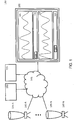
- FIG. 1 shows computer system 160 for controlling, detecting, controlling and / or analyzing biological, biochemical, chemical and / or physical processes.
- the computer system 160 shown includes multiple, but at least two units 135A to 135N (135 AN) configured to receive matter to perform at least one biological, biochemical, chemical, and / or physical process on that substance.
- Each of the units 135 AN has at least one sensor 140A to 140N (140 AN) configured to acquire measurement data relating to the process.
- the computer system 160 includes at least one display unit 100, via which the measurement data of the units 135 AN are respectively represented in a temporal correlation, which allows conclusions about a relationship between the measurement data presented.
- the measurement data of the respective units 135 AN can be displayed in separate display areas 105, 110.
- the user can use the display unit 100 with the aid of a respective slide controller 125, 130 to apply a time window via the corresponding zoom bars 113, 120 to the measured data of the respective batches, so that the course of the measured data starts from the respective time window be output via the display unit 100 regardless of an absolute time of the measurement data.
- computer system 160 may be configured to control, acquire, control, and / or analyze biological, biochemical, chemical, and / or physical processes as a Supervisory Control and Data Acquisition (SCADA) system.
- SCADA Supervisory Control and Data Acquisition
- a technical process can be computer monitored, controlled and / or regulated.
- Every layer has to fulfill a specific task within the communication between two systems.
- functions and protocols are defined that must fulfill specific tasks in the communication between two systems.
- communication or data flow passes through all 7 layers of the OSI layer model twice. Once at the transmitter and once at the receiver. Depending on how many intermediate stations the communication path has, the communication also passes through the layer model several times. Protocols in this context are a collection of rules for communication on a particular layer of the OSI model.
- the terminals of the end systems and the transmission medium are excluded from the OSI model. However, the terminals in the application layer and the transmission medium in the physical layer may be predetermined.
- the protocols of a layer are largely transparent, in particular to the protocols of the superordinate and subordinate layers, so that the mode of behavior of a protocol is as in direct communication with its counterpart on the other side.
- the transitions between the layers may in particular be interfaces that must be understood by the protocols. Because some protocols are designed for very specific applications, it is also possible for protocols to span multiple layers and cover multiple tasks. It may even be that in some connections individual tasks are performed multiple times.
- SCADA usually refers to central / distributed systems that monitor, visualize, and / or control entire installations. Most of the control is done automatically by Remote Terminal Units (RTUs) or Programmable Logic Controllers (PLCs) or Level 1 automations.
- RTUs Remote Terminal Units
- PLCs Programmable Logic Controllers
- Level 2 automation is to optimize the function of Level 1 automation as well as to output manipulated variables and / or setpoints.
- Level 3 automation is used for planning, quality assurance and / or documentation.
- the communication within a SCADA system can be based on TCP-based Internet techniques, whereby one or more serial connections in the form of point-to-point communications and / or fieldbus systems are possible.
- Level 1 Data collection usually begins with Level 1 and includes the coupling to gauges and status information such as switch positions detected by the SCADA system. The data is then presented in a user-friendly presentation, allowing control to intervene in the process.
- SCADA systems typically implement a distributed database that includes data points.
- a data point contains an input or output value that is monitored and / or controlled by the system.
- Data points can be calculated physically.
- a physical data point represents an input or output, while a calculated point results from the state of the system through mathematical operations.
- data points are treated as a combination of timestamped values.
- a series of data points allows the historical evaluation.
- the temporal correlation of data points from different units 135 A-N can advantageously be used to detect relationships of the corresponding data points or measurement data. This advantageously enables a user to influence the process (s) appropriately, e.g., by displaying the measurement data in a time-correlated manner. by setting corresponding process parameters, triggering specific processes or similar
- Each temporal correlation comprises a horizontal shifting or alignment of the measurement data of the respective units 135 A-N, so that the measurement data can be arbitrarily related to one another.
- a unit 135 AN or unit or unit includes in particular at least one reactor, eg at least one bioreactor and / or at least one chemical reactor, at least one sensor 140 AN and optionally one or more control modules and process units.
- Each unit AN may in its entirety represent, logically, a part of a production site, eg in a yeast-cultivating production plant, in which one or more process activities may be performed.
- Each unit 135 AN generates from the measurement data, the be detected by the sensor 140 AN and optionally by control modules at a given time, preferably only one batch.
- Each unit 135 AN may act independently of any other unit 135 AN.
- each unit 135 AN can be imaged with each unit 135 AN, so that all measurement data required for a process recording or process monitoring can be detected by means of at least one sensor 140 AN and displayed at the same time.
- Each unit 135 AN can be assembled individually according to a specific process, depending on the required process, from any combination of the above-mentioned components.
- a unit 135 AN may comprise in particular at least one filter which can be used for the filtration of a medium.
- it may be a filter for cross-flow filtration or tangential flow filtration or cross-flow filtration, in which liquids are filtered, for example, for the food and / or pharmaceutical industry.
- a suspension to be filtered is pumped at high speed parallel to a membrane or a filter medium, wherein a solid or permeate is withdrawn transversely to the flow direction.
- the cross-flow filtration can be used for example in microfiltration, ultrafiltration, nanofiltration, gas separation, pervaporation and / or reverse osmosis.
- Each of these units 135 AN comprises at least one sensor 140 AN and optionally one or more individual control units and process devices.
- Each unit 135 AN in its entirety, may logically represent part of a production facility, eg, a water treatment plant for the removal of heavy metals in the water treatment, in which one or more process activities may be performed.
- Each unit 135 AN generates from measured data, which are detected by the sensor 140 AN and optionally the control modules at a given time, preferably only one batch.
- Each unit 135 AN may act independently of any other unit 135 AN.
- each unit 135 AN a specific process can be mapped, so that all measurement data required for a process recording or process monitoring can be detected by means of at least one sensor 140 AN and displayed at the same time.
- Each unit 135 AN can according to a specific process according to the required process from any combination of the above Components to be put together.
- a sensor 140 AN is in particular a technical component which can quantitatively detect certain biological, biochemical, chemical and / or physical properties of its environment as a measured variable.
- the biological, biochemical, chemical and / or physical properties are converted into an electrical and / or optical signal.
- the electrical signal can then be sampled.
- a numerical measurement datum or a numerical measured value can be generated.
- the sensor 140 AN can create a data stream of the corresponding measurement data.
- Each unit 135 AN has in particular at least one sensor 140 AN, which is set up to detect specific, ie predetermined or predeterminable, measurement data relating to the process.
- it can be a gas sensor, for example an O 2 or CO 2 sensor, a pH sensor, a glucose sensor, a lactate sensor and / or any combination of the sensors, the or the are set up to detect a suitable measure in terms of the process to be performed.
- each unit 135 AN may also have one or more individual control units.
- a bioreactor 225 as a particular embodiment of a unit 135 AN (as discussed below with reference to FIGS FIG. 2
- a container which is set up to cultivate or ferment cells, microorganisms and / or small plants is described.
- biological processes for example bioconversion or biocatalysis, are used or made available in technical facilities. In doing so, an attempt is made to achieve the best possible cultivation conditions by means of important factors that can be controlled or controlled in the bioreactor 225.
- Controllable factors may be eg a composition of a nutrient solution or a substrate, an oxygen supply, a sterility or a pH.
- the purpose of culture in the bioreactor 225 may be recovery of cells, recovery of cellular components, or recovery of metabolites, which may then be used, for example, as a Active ingredient in the pharmaceutical industry or basic chemical can be used in the chemical industry.
- bioreactors are, for example, autoclavable bioreactors, in-situ sterilizable bioreactors, disposable bioreactors, stirred tank reactors, fixed bed reactors or photobioreactors.
- the production of alcoholic or alcoholic beverages, such as beer can take place in bioreactors, such as a brewing kettle.
- bioreactors are not subject to any specific restrictions.
- bioreactors for culturing cells such as bacterial, yeast, insect, plant or mammalian cells
- Bioreactors for producing metabolic products of such cells Bioreactors for the production of peptides or proteins expressed by such cells
- Bioreactors for the production of energy with the aid of such cells Bioreactors for the propagation of viruses by means of such cells
- Bioreactors for the degradation of substances by means of such cells Bioreactors for the production of foodstuffs with the aid of such cells
- Bioreactors for the production of biogas with the aid of such cells and combinations thereof.
- a control module 325 or control module (as described below with reference to FIG. 3 in particular includes variables that belong together to a physically measured or calculated size.
- the control module can also control or regulate the variables.
- Different types of control modules can be provided: Controller, Process Variable, Digital Variable and / or Offline Variable.
- a device 205, 210, 215 (as discussed below with respect to FIG. 2
- a sensor device 205 can represent an interface for the coupling of an O 2 / CO 2 analysis sensor to the unit.
- a reactor device 210 may represent an interface for the coupling of a bioreactor 225.
- a controller unit 215 may represent an interface for coupling a scale to the unit.
- a batch is a collection of data or data records which are acquired by the respective components of a unit within a specific, ie predetermined or predeterminable, period of time as measurement data.
- a batch is a record of measurement data about the process, which is carried out by the respective unit and can thus also be archived.
- Each batch can be stored in a database after the process has finished. So this can be used again and again for an analysis and / or evaluation. Thus each batch always contains the characteristic and temporally same process flows.
- the data or data records can be stored chronologically in the order in which they are combined in succession and displayed via the output unit.
- each batch may contain all the measurement data which, in the period between a filling of a unit, for example a reactor or bioreactor, be detected until a complete emptying of this unit after a specific, ie predetermined or predeterminable, time period, for example, a reaction time or growth time.
- a unit for example a reactor or bioreactor
- Measurement data or process data are, in particular, data or data records which contain information about a value of a property at a given time. Measurement data can be stored in a database.
- a substance may in particular be a liquid, a gas and / or a solid.
- the fabric may be composed of at least one component needed to facilitate the process.
- it may be useful for culturing certain organisms, e.g. Cells or certain parts of organisms, be necessary to create and maintain important conditions that ensure optimal growth of the organisms.
- such important conditions may be a composition of a nutrient medium or a substrate, an oxygen supply, a pH and / or a sterility in the bioreactor.
- Purpose of cultivation may include recovery of organisms, e.g. Cells and parts of organisms.
- Another purpose of culturing may be recovery of metabolites used as an active ingredient in the pharmaceutical industry and / or as a basic chemical in the chemical industry. Further, the purpose may be degradation of chemical compounds in e.g. Sewage treatment plants or to make a production of alcoholic beverages.
- the measurement data 335 (as discussed below with reference to FIG. 3 described) can be displayed via the display unit 100, for example in the form of waveforms.
- the measurement data may be presented in the form of one or more diagrams, eg pie charts, line charts, bar charts, organigrams, Gantt charts, flow charts, cause-and-effect diagrams, and / or block diagrams.
- the individual components of computer system 160 may be interconnected via a suitable network 145, eg, a "local area network” (LAN) or a “wide area network” (WAN).
- a suitable network 145 eg, a "local area network” (LAN) or a “wide area network” (WAN).
- the computer system 160 may include a detection unit 150 configured to automatically detect the temporal correlation.
- the detection unit 150 may compare a course of the measurement data of the respective units 135 A-N with each other and display measurement data that corresponds to each other independent of an absolute time of their detection in a corresponding manner over the display unit 100 in the respective display areas 105, 110.
- a user may use a suitable input device, such as a mouse.
- a keyboard or a keyboard and / or a computer mouse set a marker in a displayed measurement data history. On the basis of this marker, a temporal correlation of the measured data can be detected.
- each batch can be divided into different phases.
- a first phase may correspond to filling a matter into a unit
- a second phase may correspond to adding cells to the matter
- a third phase may be to adding more cells to the matter, and so forth.
- a temporal correlation of the measured data can be detected by measuring data of different units corresponding to a beginning of a specific phase.
- the computer system 160 may include a control module 155 configured to group at least two units 135 AN together so that the group may be simultaneously controlled via the control module 155 (as discussed below with reference to FIGS FIG. 4 illustrated).
- the computer system 160 in particular has the advantage that effects of different important process factors or a change of one or more such process factors can be detected in a simple and efficient manner in real time.
- a continuous optimization or improvement of the processes is made possible.
- this achieves an improved, continuous user-machine interaction, since an adjustment of biological, chemical, biochemical and / or physical process parameters during ongoing processes in the respective units 135 AN is intentionally set and / or entered depending on the corresponding state of the process can be.
- This allows coordination or coordination of the technical processes in the respective units 135 A-N.
- an alarm can be displayed via the display unit 100 if the conditions important for the respective biological, biochemical, chemical and / or physical process are exceeded or undershot, e.g. at too low or too high oxygen content and / or pH in the matter that is in the reactor.
- Another advantage is that relevant technical relationships of the processes in the respective units 135 A-N can be made accessible via the display unit 100 independently of an absolute time of the acquired measurement data via the temporal correlation.
- the temporal correlation over the duration of the processes in the respective units 135 A-N can be maintained.
- a user is enabled to more efficiently and more quickly master the technical tasks of monitoring technical parameters, controlling technical process parameters, detecting technical relationships of the various processes, and monitoring the effects of various technical parameters on a process flow in the respective 135A-N units.
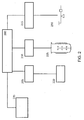
- FIG. 2 12 shows a block diagram of an exemplary unit 200.
- the unit 200 includes a reactor 225 or a filter configured to receive a matter to perform at least one biological, biochemical, chemical, and / or physical process on that substance.
- the unit 200 comprises a sensor 220, for example an O 2 / CO 2 analyzer, which is set up to acquire measurement data relating to the process.
- the unit 200 comprises a control unit 230, for example a balance and / or one or more internal control units 235. Each of the internal control units 235 may be configured to perform calculations on the acquired measurement data and / or samples of the substance on which the process is performed is to be taken and / or analyzed.
- Each of these components can be coupled to the unit 200 via a corresponding device 205, 210, 215.
- Each device 205, 210, 215 may be a communication interface or communication interface.
- the separation between units 200 and devices 205, 210, 215 has the advantage that a configuration of a unit 200 can be performed in a simple and efficient manner, since the respective components 220, 225, 230 are used with the aid of the devices 205, 210, 215 can be connected to the unit 200.
- the O 2 / CO 2 analyzer 220 is coupled to the unit 200 via a Universal Serial Bus (USB) connection, with a sensor device 205 serving as the communication interface.
- USB Universal Serial Bus
- the bioreactor 225 can, for example, transmit corresponding measurement data to the unit 200 via Ethernet and / or exchange further data with the unit 200, with a reactor device 210 serving as the communication interface for this purpose.
- the balance 230 may be coupled to the unit 200 with a control module device 215.
- required internal control modules 235 may be coupled to the unit 200.
- Each control module variable can be assigned its own MappingShortID. This has the advantage that the measurement data arriving in accordance with it can be unambiguously assigned to a control module variable.
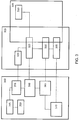
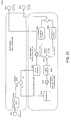
- FIG. 3 shows an overview of an exemplary structure and relationships of measurement data 335 of a unit 320, which are combined into a batch 350.
- a device 310 can communicate with each unit 320 via a control module 325.
- Each control module 325 may include control module variables 330.
- a control module may be a collection of variables and / or values belonging to a physical quantity.
- Each control module has at least one value (eg 34.5), one unit. (eg ° C), a unit and a "source" (a device from which the values or a calculation of the values originate).
- a control module can contain additional variables (eg setpoint, manipulated variable and / or low limit or alarm limit).
- a look at the measured data 335 is possible. From the user view 315 or monitoring view, each control module 325 is assigned to a unit 320 and can have one or more control module variables 330.
- control module variables can be displayed, but not all, but only the type of actual value, setpoint and / or manipulated variable.
- Each of these control module variables 330 may be assigned one or more measurement data 335.
- the user view shows a currently valid configuration of a unit 320.
- One Control module can have several variables depending on the type. However, only one measurement datum / measured value can be assigned to each variable.
- each batch 345 is assigned a start and stop time 350.
- the batch start time corresponds to the recording start and at the same time the associated biological / chemical process start on the unit.
- the batch stop time corresponds to a corresponding biological / chemical process end and at the same time to the end of recording.
- the control modules 325 configured during the batch start, their control module variables 330 and the measurement data 335 accumulating during the process are likewise stored in the batch 345.
- each batch 345 stores a snapshot of the currently valid configuration as well as all measurement data or process data.
- the computer system 160 allows administration of an already new / different / changed configuration (new or changed devices on the device, renamed device, changed ControlModule names, deleted device) of the respective devices 205, 210, 215.
- a monitoring of the measurement data or process data to a unit 320 is made possible.
- the communication view allows a display of a flow of measured data as well as an assignment of the measured data.
- the batches 345 and their associated process data can be stored in a database.
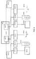
- a detection unit 150 in the computer system 160 indicate the temporal correlation by uniting two units 135 AN into a group 400 (unit grouping).
- FIG. 4 shows an example of a group 400 of at least two units 405 AN.
- the units 405 are AN or units of the same type or have the same sensors 420 AN or individual control units 430A-N.
- the connection of the respective components to the respective units 405 AN takes place analogously to the connection as described above with reference to FIG. 2
- the sensors 420 AN are connected to the respective unit 405 AN by means of a respective sensor device 406 AN.
- the reactors 410 AN can be coupled to the respective unit 405 AN by means of corresponding reactor devices 410 AN.
- the individual control units 430 AN can be coupled to the respective unit 405 AN by means of corresponding individual control devices 415 AN.
- the respective internal control modules 435 AN may be coupled to the respective units 405 AN become.
- the measurement data of the respective batches can be output via the display unit 100 using the display unit 100 either in a common display area or optionally in separate display areas.
- a group 400 may be created from an arbitrary combination of the units 405 A-N to be time correlated.
- each user has the option of taking a snapshot of the measurement data, which are displayed in a time-correlated manner via the display unit 100, by inputting a corresponding command, e.g.
- Each group 400 may also automatically during running processes, e.g. by having a specific, i. predetermined or predeterminable, condition is met, or manually resolved by the user.
- measurement data of the respective sensor are combined into a separate batch via the respective process of the reactor and / or filter and optionally the respective additional control modules and internal control modules and displayed via the display unit 100.
- the computer system 160 may include a default according to which the display unit 100 always uses the most recent ones N data or records that have been recorded and added to the batch are displayed, where N is a specific, ie predetermined or predeterminable, number of data or records defined.
- the temporal correlation can be displayed by choosing a time window specific, ie predetermined or predeterminable magnitude is applied to the measurement data of the respective units 405 AN such that measurement data located in the time window are displayed time-correlated independent of an absolute time of their acquisition.
- This temporal correlation or synchronization of the measurement data can be retained in the display unit 100, even if new measurement data is recorded in the batch.
- the display unit 100 may represent the temporal correlation of the data that is within the time window.
- the synchronization is a special type of temporal correlation, since measurement data that are changed in a display area or display window in size relative to measurement data that are displayed in a second display area or display window, in particular upsets or be stretched.
- the temporal correlation may be displayed by correlating measurement data, measured by sensors of the respective units 405 AN at different time intervals, with each other in temporal correlation.
- the size of the time window which is applied to the respective batch can be adapted such that the measured data correspond in their time intervals.
- the temporal correlation can be set manually by a user.
- FIG. 5 1 shows an exemplary, simplified display of a display unit 500, in which a first slider 525 is present in the upper display area 505, which can be moved via a first zoom bar 515.
- a time window can be applied to the measurement data 335 of a first batch, also referred to below as trend. Since the first slider 525 does not abut on the right edge, the upper trend indicates the measurement data of the batch from the selected time window regardless of an absolute time of detection of the measurement data 335.
- measurement data 335 becomes another unit displayed, wherein a second slider 530 can be moved via a second zoom bar 520. In this case, synchronization of the measurement data of both units is not possible because the total time span of the two trends is too different.
- a user may specify a width of the time window, i. controlling a number of measurement data 335 to be displayed by using a suitable input device to drive a point on the zoom bar 515, 520 located outside the thumb.
- a suitable input device to drive a point on the zoom bar 515, 520 located outside the thumb.
- FIG. 6 shows an example of a partially possible action.
- FIG. 6 via the display unit 600 in a first display area 605 a first measurement data trend or trend.
- the slider 625 is located at the far left of the zoom bar 615. This may mean, for example, that the first measurement data 335 of the corresponding batch 345 is displayed.
- a second display area 610 a second measurement data profile is displayed, wherein the slider 630 is located on the far right of the corresponding zoom bar 620.
- the two trends can be linked together using a corresponding button 635.
- FIG. 7 shows two measured data profiles or, in which a synchronization of the time axis is possible, wherein FIG. 8 shows the result of the synchronization of the time axes.
- FIG. 7 a display unit 700, which displays a first measurement data course of a first unit 135 AN, 200, 320 in a first display area 705 and a second measurement data course of a second unit 135 AN, 200, 320 in a second display area 710.
- the respective sliders 725, 730 have the same size and are in the same area of the respective zoom bar 715, 720.
- the two measured data profiles can be synchronized by activating a corresponding button 740.
- the technical realization will be discussed below with reference to FIG. 9 explained.
- FIG. 8 shows the two measured data curves as in FIG. 7 after synchronization due to activation of the button 740 (FIG. FIG. 7 ) has been activated.
- the deflections or changes of the respective measurement data in the respective display areas 805, 810 are now displayed synchronously with one another, ie in mutually equal or similar distances.
- the relative size of the slider of the second display unit 830 has decreased, so that fewer measurement data are displayed in the corresponding display area 810 in order to enable the synchronized representation of the measurement data. It depends on which batch has been running for some time. So it is quite possible that the lower or the upper trend or its zoom bar is reduced.
- a command "SynchTrendsCommand” can be stored in a class “TrendDisplay”, i. a Model View ViewModel (MWM) of the trend to be implemented.
- MWM is a variant of the Model View Controller Pattern (MVC) that separates user interface and user interface (UI) representation and logic, and is supported by the UI platform WPF.
- MVC Model View Controller Pattern
- An exemplary system includes a universal computing device in the form of a conventional computing environment 20, such as a personal computer (PC) 20, having a processor unit 22, a system memory 24, and a system bus 26 containing a variety of system components, including system memory 24 and the processor unit 22 connects.
- the processor unit 22 may perform arithmetic, logic and / or control operations by accessing the system memory 24.
- the system memory 24 may store information and / or instructions for use in combination with the processor unit 22.
- System memory 24 may include volatile and non-volatile memory, such as random access memory (RAM) 28 and read-only memory (ROM) 30 include.
- a basic input-output system (BIOS) containing the basic routines that help to transfer information between the elements within the personal computer 20, for example, during start-up, may be stored in the ROM 30.
- the system bus 26 may be one of many bus structures, including a memory bus or memory controller, a peripheral bus, and a local bus employing a particular bus architecture from a variety of bus architectures.
- the PC 20 may further include a hard disk drive 32 for reading or writing a hard disk (not shown) and an external disk drive 34 for reading or writing a removable disk 36 or a removable medium.
- the removable disk may be a magnetic disk for a magnetic disk drive or an optical disk such as a floppy disk. a CD-ROM, for an optical disk drive.
- the hard disk drive 32 and the external disk drive 34 are each connected to the system bus 26 via a hard disk drive interface 38 and a disk drive interface 40.
- the drives and associated computer-readable media provide nonvolatile storage of computer readable instructions, data structures, program modules, and other data to the PC 20.
- the data structures may include the relevant data for implementing a method as described above.
- the exemplary environment utilizes a hard disk (not shown) and an external disk 42, it will be apparent to those skilled in the art that other types of computer-readable media that can store computer-accessible data may be used in the exemplary work environment, such as a computer. magnetic cassettes, flash memory cards, digital video disks, random access memory, read-only memory, etc.
- a plurality of program modules in particular an operating system (not shown), one or more application programs 44 or program modules (not shown) and program data 46 may be stored on the hard disk, the external disk 42, the ROM 30 or the RAM 28 ,
- the application programs can perform at least some of the functionality, as in FIG. 1 respectively.
- FIGS. 5 to 9 shown include.
- a user may enter commands and information as described above into the PC 20 by means of input devices, e.g. a keyboard 48 and a computer mouse 50.
- Other input devices may include a microphone and / or other sensors, a joystick, a game pad, a scanner, or the like.
- These or other input devices may be connected to the processor unit 22 via a serial interface 52 which is coupled to the system bus 26 or may be interfaced with other interfaces, such as e.g. a parallel interface 54, a game port or a universal serial bus (USB).
- a printer 56 The printer 56 and other parallel input / output devices may be connected to the processor unit 22 through the parallel interface 54.
- a monitor 58 or other type of display device (s) is / are connected to the system bus 26 by means of an interface, such as e.g. a video input / output 60.
- the computing environment 20 may include other peripheral output devices (not shown), e.g. Speaker or acoustic outputs include.
- the computing environment 20 may communicate with other electronic devices, such as a computer, a corded phone, a cordless phone, a personal digital assistant (PDA), a television, or the like. To communicate, the computing environment 20 may operate in a networked environment using connections to one or more electronic devices.
- FIG. 11 illustrates the computing environment networked with a remote computer 62.
- the remote computer 62 may be another computing environment, such as a server, router, network PC, peer device, or other common computing environment Network node and may include many or all of the elements described above with respect to the computing environment 20.
- the logical connections, as in FIG. 11 include a local area network (LAN) 64 and a wide area network (WAN) 66.
- LAN local area network
- WAN wide area network
- Such networking environments are commonplace in offices, corporate-wide computer networks, intranets, and the Internet.
- the computing environment 20 When a computing environment 20 is used in a LAN network environment, the computing environment 20 may be connected to the LAN 64 through a network input / output 68.
- the computing environment 20 When the computing environment 20 is used in a WAN networking environment, the computing environment 20 may include a modem 70 or other means of establishing communication over the WAN 66.
- the modem 70 which may be internal and external to the computing environment 20, is connected to the system bus 26 via the serial interface 52.
- program modules that are relative to the computing environment 20, or portions thereof may be stored in a remote storage device that is accessible to or from a remote computer 62.
- other data relevant to the method or system described above may be accessible on or from the remote computer 62.
Claims (14)
- Système d'ordinateur (160) pour la commande, l'acquisition, la configuration et/ou l'analyse de processus biologiques, biochimiques, chimiques et/ou physiques dans des bioréacteurs et/ou des réacteurs chimiques, comportant:au moins deux unités (135 A-N, 200, 320, 405 A-N),comportant chacune au moins un bioréacteur ou un réacteur chimique, qui est agencé pour recevoir une matiète, afin d'y effectuer au moins un processus biologique, biochimique, chimique et/ou physique ;chacune des unités (135 A-N, 200, 320, 405 A-N) comportant au moins un senseur (140 A-N, 220, 420 A-N) associé au dit bioréacteur ou réacteur chimique et agencé pour acquérir des données de mesure (335) relatives au processus biologique, biochimique, chimique et/ou physique ;au moins une unité d'affichage (100, 500, 600, 700, 800) qui représente les données de mesure (335) des processus de chacune des deux unités (135 A-N, 200, 320, 405 AN) en une corrélation chronologique qui permet des révélations concernant une relation entre les données de mesure (335) représentées, etcaractérisé parune unité d'acquisition (150) agencée pour- reconnaître la corrélation chronologique en comparant entre elles les évolutions des données de mesure (335) de chacune des unités (135 A-N, 200, 320, 405 AN);et- permettre un affichage via l'unité d'affichage (100, 500, 600, 700, 800) de données de mesure correspondant l'une à l'autre (335) en provenance de chacune des unités (135 A-N, 200, 320, 405 A-N), indépendamment d'un temps d'acquisition absolu.
- Système d'ordinateur selon la revendication 1, dans lequel la corrélation chronologique est représentable moyennant une fenêtre de temps de dimension spécifique appliquée aux données de mesure (335) de chacune des unités (135 A-N, 200, 320, 405 A-N) de telle sorte que les données de mesure (335) se trouvant dans la fenêtre de temps sont représentées en corrélation chronologique indépendamment d'un temps d'acquisition absolu.
- Système d'ordinateur selon l'une des revendications précédentes dans lequel la corrélation chronologique est réglable en fonction de données introduites par un utilisateur.
- Système d'ordinateur selon la revendication 3 dans lequel les données de mesure (335) des deux unités (135 A-N, 200, 320, 405 A-N) sont affichées par l'unité d'affichage (100, 500, 600, 700, 800) chaque fois dans un domaine d'affichage (105, 110, 505, 510, 605, 610, 705, 710, 805, 810) ; le réglage pouvant encore comporter l'application par l'utilisateur, dans chaque domaine d'affichage (105, 110, 505, 510, 605, 610, 705, 710, 805, 810), d'une fenêtre de temps chaque fois à un moment spécifique des données de mesure (335), moyennant un curseur (825, 830) qui est déplaçable le long des données de mesure (335) dans chacun des domaines d'affichage (105, 110, 505, 510, 605, 610, 705, 710, 805, 810).
- Système d'ordinateur selon l'une des revendications précédentes comportant en plus un module de commande (155) agencé pour réunir au moins deux unités (135 A-N, 200, 320, 405 A-N) en un groupe.
- Système d'ordinateur selon la revendication 5 dans lequel le module de commande (155) est agencé de manière à relier entre elles les fenêtres de temps qui sont appliquées sur les données de mesure (335) de chacune des unités (135 A-N, 200, 320, 405 A-N) et affichées chaque fois dans un domaine d'affichage (105, 110, 505, 510, 605, 610, 705, 710, 805, 810) de telle sorte qu'un utilisateur peut commander les fenêtres de temps moyennant un curseur (825, 830) en les déplaçant de façon synchrone sur les données de mesure (335) de chacune des unités (135 A-N, 200, 320, 405 A-N).
- Système d'ordinateur selon la revendication 5, dans lequel le module de commande (155) est agencé de manière à démarrer le processus à effectuer sur la matière de chacune des unités (135 A-N, 200, 320, 405 A-N) au même moment, indépendamment du moment absolu.
- Procédé implémenté par ordinateur pour la commande, l'acquisition, la configuration et/ou l'analyse de processus biologiques, biochimiques, chimiques et/ou physiques dans des bioréacteurs et/ou des réacteurs chimiques, comportant:la mise à disposition d'au moins deux unités (135 A-N, 200, 320, 405 A-N) comportant chacune au moins un bioréacteur ou un réacteur chimique, qui est agencé pour recevoir une matière, afin d'y effectuer au moins un processus biologique, biochimique, chimique et/ou physique, chacune des unités (135 A-N, 200, 320, 405 AN) comportant au moins un senseur (140 A-N, 220, 420 A-N) associé au dit bioréacteur ou réacteur chimique,l'acquisition par les senseurs de données de mesure (335) concernant chacun des processus biologiques, biochimiques, chimiques et/ou physiques, etl'affichage par une unité d'affichage (100, 500, 600, 700, 800) des données de mesure acquises (335) des processus des deux unités (135 A-N, 200, 320, 405 A-N), dans une corrélation chronologique,ladite corrélation chronologique permettant des révélations concernant une relation entre les données de mesure (335) représentées ;caractérisé par les étapes :reconnaissance de la corrélation chronologique par une unité d'acquisition (150), par comparaison des entre elles des évolutions des données de mesure (335) de chacune des unités (135 A-N, 200, 320, 405 A-N) ; etaffichage via l'unité d'affichage (100, 500, 600, 700, 800) de données de mesure correspondant l'une à l'autre (335) en provenance de chacune des unités (135 A-N, 200, 320, 405 A-N), indépendamment d'un temps d'acquisition absolu.
- Procédé selon la revendication 8 dans lequel on peut représenter la corrélation chronologique en appliquant une fenêtre de temps de dimension spécifique aux données de mesure (335) de chacune des unités (135 A-N, 200, 320, 405 A-N) de telle sorte que les données de mesure (335) se trouvant dans la fenêtre de temps sont représentées en corrélation chronologique indépendamment d'un temps d'acquisition absolu.
- Procédé selon l'une des revendications 8 ou 9 dans lequel on peut régler la corrélation chronologique en fonction de données introduites par un utilisateur ;les données de mesure (335) des deux unité (135 A-N, 200, 320, 405 A-N) peuvent être affichées par l'unité d'affichage (100, 500, 600, 700, 800) chaque fois dans un domaine d'affichage (105, 110, 505, 510, 605, 610, 705, 710, 805, 810) ; etle réglage peut encore comporter l'application par l'utilisateur, dans chaque domaine d'affichage (105, 110, 505, 510, 605, 610, 705, 710, 805, 810), d'une fenêtre de temps chaque fois à un moment spécifique des données de mesure (335) moyennant un curseur (825, 830) déplaçable le long des données de mesure (335) dans chacun des domaines d'affichage (105, 110, 505, 510, 605, 610, 705, 710, 805, 810).
- Procédé selon l'une des revendications 8 à 10 comportant en plus :rassemblement d'au moins deux unités (135 A-N, 200, 320, 405 A-N) en un groupe moyennant un module de commande (155) de telle sorte que le groupe est commandable par ledit module de commande (155) ;le procédé comportant encore :liaison entre elles des fenêtres de temps appliquées sur les données de mesure (335) de chacune des unités (135 A-N, 200, 320, 405 A-N) et affichées chaque fois dans un domaine d'affichage (105, 110, 505, 510, 605, 610, 705, 710, 805, 810), via le module de commande, de telle sorte qu'un utilisateur peut commander les fenêtres de temps moyennant un curseur (825, 830), en déplaçant les fenêtres de temps de manière synchrone sur les données de mesure (335) de chacune des unités (135 A-N, 200, 320, 405 A-N).
- Procédé selon l'une des revendications 8 à 11 comportant en plus :démarrage via le module de commande (155) des processus à effectuer sur la matière de chacune des unités (135 A-N, 200, 320, 405 A-N) au même moment, indépendamment du moment absolu.
- Produit « programme d'ordinateur » comportant des parties de programme qui lorsqu'elles sont chargées dans un ordinateur sont agencées pour effectuer un procédé implémenté par ordinateur selon l'une des revendications 8 à 12.
- Interface graphique pour la commande, l'acquisition, la configuration et/ou l'analyse de processus biologiques, biochimiques, chimiques et/ou physiques dans des bioréacteurs et/ou des réacteurs chimiques, comportant:au moins deux domaines d'affichage (105, 110, 505, 510, 605, 610, 705, 710, 805, 810) de dimension spécifique et de position spécifique, chaque domaine d'affichage (105, 110, 505, 510, 605, 610, 705, 710, 805, 810) est associé à une unité (135 A-N, 200, 320, 405 A-N), chaque unité comportant au moins un bioréacteur ou un réacteur chimique agencé pour recevoir une matière afin d'y effectuer au moins un processus biologique, biochimique, chimique et/ou physique,chaque unité (135 A-N, 200, 320, 405 A-N) comportant au moins un senseur associé au dit bioréacteur ou réacteur chimique et agencé pour acquérir des données de mesure (335) relatives au processus biologique, biochimique, chimique et/ou physique,les données de mesure (335) acquises des processus des deux unités (135 A-N, 200, 320, 405 A-N) étant représentées dans chaque domaine d'affichage (105, 110, 505, 510, 605, 610, 705, 710, 805, 810) chaque fois dans une corrélation chronologique qui permet des révélations concernant une relation entre les données de mesure (335) représentées,caractérisée en cequ'on reconnaît la corrélation chronologique par comparaison entre elles des évolutions des données de mesure (335) de chacune des unités (135 A-N, 200, 320, 405 A-N) ; etqu'on affiche dans le domaine d'affichage correspondant, via l'unité d'affichage (100, 500, 600, 700, 800), les données de mesure (335) correspondant à chacune des unités (135 A-N, 200, 320, 405 A-N), indépendamment d'un temps d'acquisition absolu.
Priority Applications (4)
| Application Number | Priority Date | Filing Date | Title |
|---|---|---|---|
| EP14002995.0A EP2990900B1 (fr) | 2014-08-29 | 2014-08-29 | Système et méthode pour le contrôle, l'acquisition, la configuration et/ou l'analyse des processus biologiques, biochimiques, chimiques et/ou physiques en utilisant une corrélation de données |
| PCT/EP2015/001316 WO2016029979A1 (fr) | 2014-08-29 | 2015-06-30 | Système informatique, procédé, logiciel et interface utilisateur, pour commander, détecter, réguler et/ou analyser des processus biologiques, biochimiques, chimiques et/ou physiques |
| CN201580046408.5A CN106796431B (zh) | 2014-08-29 | 2015-06-30 | 用于控制、检测、调节和/或分析生物、生物化学、化学和/或物理过程的系统、方法和用户接口 |
| US15/506,955 US11158399B2 (en) | 2014-08-29 | 2015-06-30 | System, method, computer program product and user interface for controlling, detecting, regulating and/or analyzing biological, biochemical, chemical and/or physical processes |
Applications Claiming Priority (1)
| Application Number | Priority Date | Filing Date | Title |
|---|---|---|---|
| EP14002995.0A EP2990900B1 (fr) | 2014-08-29 | 2014-08-29 | Système et méthode pour le contrôle, l'acquisition, la configuration et/ou l'analyse des processus biologiques, biochimiques, chimiques et/ou physiques en utilisant une corrélation de données |
Publications (2)
| Publication Number | Publication Date |
|---|---|
| EP2990900A1 EP2990900A1 (fr) | 2016-03-02 |
| EP2990900B1 true EP2990900B1 (fr) | 2017-04-12 |
Family
ID=51518501
Family Applications (1)
| Application Number | Title | Priority Date | Filing Date |
|---|---|---|---|
| EP14002995.0A Revoked EP2990900B1 (fr) | 2014-08-29 | 2014-08-29 | Système et méthode pour le contrôle, l'acquisition, la configuration et/ou l'analyse des processus biologiques, biochimiques, chimiques et/ou physiques en utilisant une corrélation de données |
Country Status (4)
| Country | Link |
|---|---|
| US (1) | US11158399B2 (fr) |
| EP (1) | EP2990900B1 (fr) |
| CN (1) | CN106796431B (fr) |
| WO (1) | WO2016029979A1 (fr) |
Families Citing this family (12)
| Publication number | Priority date | Publication date | Assignee | Title |
|---|---|---|---|---|
| CN106999347A (zh) | 2014-08-08 | 2017-08-01 | 弗雷蒙科学公司 | 在感测装有生物物质的包袋的生理和/或物理参数中使用的智能包袋 |
| US10866173B2 (en) | 2018-05-07 | 2020-12-15 | Fremon Scientific, Inc. | Thawing biological substances |
| US10634558B1 (en) * | 2018-11-13 | 2020-04-28 | Anna Ailene Scott | Air quality monitoring system and enhanced spectrophotometric chemical sensor |
| US10697947B1 (en) | 2019-01-23 | 2020-06-30 | Project Canary, Inc. | Apparatus and methods for reducing fugitive gas emissions at oil facilities |
| EP3702849B1 (fr) * | 2019-02-26 | 2023-07-26 | Sartorius Stedim Data Analytics AB | Commande de processus optimisée |
| US11150167B1 (en) | 2020-04-03 | 2021-10-19 | Project Canary, Pbc | Air sampling actuator and associated method |
| EP4200583A1 (fr) | 2020-09-10 | 2023-06-28 | Project Canary, PBC | Système et procédé de surveillance de qualité d'air |
| DE102020124301A1 (de) | 2020-09-17 | 2022-03-17 | GDS Holding GmbH | Verfahren zur Verlängerung der Haltbarkeit von nicht fermentierten Lebensmitteln und Mikroorganismen zur Verwendung in einem solchen Verfahren |
| US11774426B1 (en) | 2022-03-25 | 2023-10-03 | Project Canary, Pbc | Emissions detection system and methods |
| US11861753B1 (en) | 2023-02-01 | 2024-01-02 | Project Canary, Pbc | Air quality monitors minimization system and methods |
| US11727519B1 (en) | 2023-02-01 | 2023-08-15 | Project Canary, Pbc | Air quality monitors minimization system and methods |
| US11887203B1 (en) | 2023-02-01 | 2024-01-30 | Project Canary, Pbc | Air quality monitors minimization system and methods |
Citations (4)
| Publication number | Priority date | Publication date | Assignee | Title |
|---|---|---|---|---|
| EP1184073A2 (fr) | 1998-08-13 | 2002-03-06 | Symyx Technologies | Système de commande pour réacteur |
| US6727096B1 (en) * | 1998-08-13 | 2004-04-27 | Symyx Technologies, Inc. | Analysis and control of parallel chemical reactions |
| US20050197805A1 (en) | 2001-03-01 | 2005-09-08 | Fisher-Rosemount Systems, Inc. | Data presentation system for abnormal situation prevention in a process plant |
| EP2172820A1 (fr) | 2008-10-06 | 2010-04-07 | Basf Se | Procédé et système destinés à l'analyse automatique de données de processus |
Family Cites Families (12)
| Publication number | Priority date | Publication date | Assignee | Title |
|---|---|---|---|---|
| US5134574A (en) * | 1990-02-27 | 1992-07-28 | The Foxboro Company | Performance control apparatus and method in a processing plant |
| US6546134B1 (en) * | 1999-03-29 | 2003-04-08 | Ruth Shrairman | System for assessment of fine motor control in humans |
| US6421571B1 (en) * | 2000-02-29 | 2002-07-16 | Bently Nevada Corporation | Industrial plant asset management system: apparatus and method |
| TWI246007B (en) * | 2003-09-30 | 2005-12-21 | Toshiba Corp | Data management collection system |
| PL1969507T3 (pl) * | 2005-12-19 | 2012-09-28 | Gambro Lundia Ab | Aparat medyczny z ulepszonym interfejsem użytkownika |
| JP4337841B2 (ja) * | 2006-06-07 | 2009-09-30 | オムロン株式会社 | データ表示装置およびその制御方法、データ表示装置制御プログラム、ならびに該プログラムを記録した記録媒体 |
| US8823709B2 (en) * | 2007-11-01 | 2014-09-02 | Ebay Inc. | User interface framework for viewing large scale graphs on the web |
| CN102405447A (zh) * | 2009-04-11 | 2012-04-04 | Abb股份公司 | 机器人系统 |
| CN103476337A (zh) * | 2011-04-15 | 2013-12-25 | 株式会社日立医疗器械 | 生物体光测量装置、生物体光测量装置的工作方法以及生物体光测量数据的解析显示方法 |
| JP5866446B2 (ja) * | 2012-07-03 | 2016-02-17 | シャープ株式会社 | グラフ描画装置、グラフ描画方法、工程管理システム、工程管理方法、制御プログラムおよび可読記憶媒体 |
| GB201213506D0 (en) * | 2012-07-30 | 2012-09-12 | Tap Biosystems Phc Ltd | Bioreactor vessels and associated bioreactor systems |
| US9405291B2 (en) * | 2012-07-31 | 2016-08-02 | Fisher-Rosemount Systems, Inc. | Systems and methods to monitor an asset in an operating process unit |
-
2014
- 2014-08-29 EP EP14002995.0A patent/EP2990900B1/fr not_active Revoked
-
2015
- 2015-06-30 US US15/506,955 patent/US11158399B2/en active Active
- 2015-06-30 WO PCT/EP2015/001316 patent/WO2016029979A1/fr active Application Filing
- 2015-06-30 CN CN201580046408.5A patent/CN106796431B/zh active Active
Patent Citations (4)
| Publication number | Priority date | Publication date | Assignee | Title |
|---|---|---|---|---|
| EP1184073A2 (fr) | 1998-08-13 | 2002-03-06 | Symyx Technologies | Système de commande pour réacteur |
| US6727096B1 (en) * | 1998-08-13 | 2004-04-27 | Symyx Technologies, Inc. | Analysis and control of parallel chemical reactions |
| US20050197805A1 (en) | 2001-03-01 | 2005-09-08 | Fisher-Rosemount Systems, Inc. | Data presentation system for abnormal situation prevention in a process plant |
| EP2172820A1 (fr) | 2008-10-06 | 2010-04-07 | Basf Se | Procédé et système destinés à l'analyse automatique de données de processus |
Non-Patent Citations (6)
| Title |
|---|
| EPPENDORF: "software manual", DASGIP DOCUMENTATION WIZZARD,, July 2011 (2011-07-01), pages 1 - 26, XP055452673 |
| EPPENDORF: "Software manual", DASWARE DISCOVER,, 2013, pages 1 - 78, XP055452677 |
| INTERNETDOKUMENT: TIMESEARCHER AUFRUFBAR UNTER DER INTERNETADRESSE, Retrieved from the Internet <URL:http//www.cs, umd.edu/hcil/timesearcher> |
| INTERNETDOKUMENT: TIMESEARCHER AUFRUFBAR UNTER DER INTERNETADRESSE, Retrieved from the Internet <URL:http://www.cs.umd.edu/hcil/timesearcher/docs/ts2 userManua).htm!#sec5.5> |
| INTERNETDOKUMENT: TIMESEARCHER, LICENCSE - DOWNLOAD AUFRUFBAR UNTER DER INTERNETADRESSE, Retrieved from the Internet <URL:http://www.cs.umd.edu/hcil/timesearcher/dist2/demos 4Gf5x> |
| PAOLO BUONO ET AL.: "Interactive Pattern Search in Time Series", PROC. OF VDA, 2005, pages 1 - 11, XP055452683 |
Also Published As
| Publication number | Publication date |
|---|---|
| EP2990900A1 (fr) | 2016-03-02 |
| US20170277829A1 (en) | 2017-09-28 |
| CN106796431B (zh) | 2022-03-25 |
| US11158399B2 (en) | 2021-10-26 |
| CN106796431A (zh) | 2017-05-31 |
| WO2016029979A1 (fr) | 2016-03-03 |
Similar Documents
| Publication | Publication Date | Title |
|---|---|---|
| EP2990900B1 (fr) | Système et méthode pour le contrôle, l'acquisition, la configuration et/ou l'analyse des processus biologiques, biochimiques, chimiques et/ou physiques en utilisant une corrélation de données | |
| DE2323416A1 (de) | Verfahren und anordnung zur regelung und analyse biochemischer prozesse | |
| DE102006045428B4 (de) | Verfahren und System zur Steuerung eines Batch-Prozesses | |
| DE112019002030T5 (de) | Qualitätsüberprüfungs-Verwaltungssystem mit konfigurierbaren Ausnahmeregeln | |
| EP2722657B1 (fr) | Pèse-personne avec surveillance par caméra et système de thérapie par dialyse comprenant un processus de pesée surveillé par caméra | |
| EP2013328A2 (fr) | Système d'analyses de procédés à prélèvement stérile de matériaux sensibles mécaniquement, à partir d'un bioréacteur | |
| DE112011101738T5 (de) | Mehrstufiges Prozessmodellierungsverfahren | |
| DE112005001012T5 (de) | Anwender konfigurierbare Alarme und Alarmverfolgung für Verfahrenssteuersysteme | |
| WO2021043712A1 (fr) | Système de planification, d'entretien, de gestion et d'optimisation d'un processus de production | |
| EP1539922B1 (fr) | Procede de mise en culture de cellules, notamment de cellules humaines ou animales | |
| EP1877535B1 (fr) | Systeme de culture cellulaire, et procede de culture cellulaire | |
| DE102016117585A1 (de) | Verfahren und Vorrichtung zur Bestimmung von Schritten für eine multi-Zufallsvariablen Batch-Steuerungs-Analyse | |
| EP3296387B1 (fr) | Procede de surveillance de bioprocessus | |
| DE102004025876B4 (de) | Vorrichtung und Verfahren zur Stapeleigenschaftsschätzung | |
| WO2018185052A1 (fr) | Procédé pour la régulation d'un procédé biotechnologique | |
| DE69838673T2 (de) | Mikrobiosensor zum kontinuierlichen nachweis von chemischen substanzen in flüssigkeiten | |
| DE102009022351A1 (de) | Modulares Produktionssystem zur automatischen Herstellung von dreidimensionalen Gewebestrukturen | |
| WO1989012091A1 (fr) | Procede et agencement pour reguler un processus de croissance biologique | |
| DE10354406B4 (de) | Verfahren zur Prozesszustandsklassifikation bei der Messdatenverarbeitung träger Prozessgrößen | |
| DE19921999C2 (de) | Vorrichtung und Verfahren zur Überwachung und Kontrolle von biologisch aktiven Fluiden | |
| EP3593895B1 (fr) | Procédé d'optimisation de la sécurisation de production des installations à membrane | |
| EP4029024A1 (fr) | Procédé et appareil pour aider à la production d'un matériau fonctionnel | |
| EP0889950B1 (fr) | Procede pour l'analyse des proprietes d'un systeme biologique | |
| WO2020007577A1 (fr) | Procédé de fonctionnement d'un dispositif médical et dispositif médical fonctionnant selon ce procédé | |
| DE4415602A1 (de) | Prozeßführung der aeroben Abwasserbehandlung mit Hilfe eines Verfahrens und einer Anlage, die eine an der Substratabbaurate der Organismen ausgerichtete Steuerung/Regelung ermöglicht |
Legal Events
| Date | Code | Title | Description |
|---|---|---|---|
| PUAI | Public reference made under article 153(3) epc to a published international application that has entered the european phase |
Free format text: ORIGINAL CODE: 0009012 |
|
| 17P | Request for examination filed |
Effective date: 20150702 |
|
| AK | Designated contracting states |
Kind code of ref document: A1 Designated state(s): AL AT BE BG CH CY CZ DE DK EE ES FI FR GB GR HR HU IE IS IT LI LT LU LV MC MK MT NL NO PL PT RO RS SE SI SK SM TR |
|
| AX | Request for extension of the european patent |
Extension state: BA ME |
|
| STAA | Information on the status of an ep patent application or granted ep patent |
Free format text: STATUS: EXAMINATION IS IN PROGRESS |
|
| GRAP | Despatch of communication of intention to grant a patent |
Free format text: ORIGINAL CODE: EPIDOSNIGR1 |
|
| STAA | Information on the status of an ep patent application or granted ep patent |
Free format text: STATUS: GRANT OF PATENT IS INTENDED |
|
| INTG | Intention to grant announced |
Effective date: 20161205 |
|
| GRAS | Grant fee paid |
Free format text: ORIGINAL CODE: EPIDOSNIGR3 |
|
| GRAA | (expected) grant |
Free format text: ORIGINAL CODE: 0009210 |
|
| STAA | Information on the status of an ep patent application or granted ep patent |
Free format text: STATUS: THE PATENT HAS BEEN GRANTED |
|
| AK | Designated contracting states |
Kind code of ref document: B1 Designated state(s): AL AT BE BG CH CY CZ DE DK EE ES FI FR GB GR HR HU IE IS IT LI LT LU LV MC MK MT NL NO PL PT RO RS SE SI SK SM TR |
|
| REG | Reference to a national code |
Ref country code: GB Ref legal event code: FG4D Free format text: NOT ENGLISH |
|
| REG | Reference to a national code |
Ref country code: CH Ref legal event code: NV Representative=s name: PATENTANWAELTE SCHAAD, BALASS, MENZL AND PARTN, CH Ref country code: CH Ref legal event code: EP |
|
| REG | Reference to a national code |
Ref country code: IE Ref legal event code: FG4D Free format text: LANGUAGE OF EP DOCUMENT: GERMAN |
|
| REG | Reference to a national code |
Ref country code: AT Ref legal event code: REF Ref document number: 884495 Country of ref document: AT Kind code of ref document: T Effective date: 20170515 |
|
| REG | Reference to a national code |
Ref country code: DE Ref legal event code: R096 Ref document number: 502014003335 Country of ref document: DE |
|
| REG | Reference to a national code |
Ref country code: NL Ref legal event code: FP |
|
| REG | Reference to a national code |
Ref country code: FR Ref legal event code: PLFP Year of fee payment: 4 |
|
| REG | Reference to a national code |
Ref country code: SE Ref legal event code: TRGR |
|
| REG | Reference to a national code |
Ref country code: LT Ref legal event code: MG4D |
|
| PG25 | Lapsed in a contracting state [announced via postgrant information from national office to epo] |
Ref country code: GR Free format text: LAPSE BECAUSE OF FAILURE TO SUBMIT A TRANSLATION OF THE DESCRIPTION OR TO PAY THE FEE WITHIN THE PRESCRIBED TIME-LIMIT Effective date: 20170713 Ref country code: NO Free format text: LAPSE BECAUSE OF FAILURE TO SUBMIT A TRANSLATION OF THE DESCRIPTION OR TO PAY THE FEE WITHIN THE PRESCRIBED TIME-LIMIT Effective date: 20170712 Ref country code: HR Free format text: LAPSE BECAUSE OF FAILURE TO SUBMIT A TRANSLATION OF THE DESCRIPTION OR TO PAY THE FEE WITHIN THE PRESCRIBED TIME-LIMIT Effective date: 20170412 Ref country code: ES Free format text: LAPSE BECAUSE OF FAILURE TO SUBMIT A TRANSLATION OF THE DESCRIPTION OR TO PAY THE FEE WITHIN THE PRESCRIBED TIME-LIMIT Effective date: 20170412 Ref country code: FI Free format text: LAPSE BECAUSE OF FAILURE TO SUBMIT A TRANSLATION OF THE DESCRIPTION OR TO PAY THE FEE WITHIN THE PRESCRIBED TIME-LIMIT Effective date: 20170412 Ref country code: LT Free format text: LAPSE BECAUSE OF FAILURE TO SUBMIT A TRANSLATION OF THE DESCRIPTION OR TO PAY THE FEE WITHIN THE PRESCRIBED TIME-LIMIT Effective date: 20170412 |
|
| PG25 | Lapsed in a contracting state [announced via postgrant information from national office to epo] |
Ref country code: IS Free format text: LAPSE BECAUSE OF FAILURE TO SUBMIT A TRANSLATION OF THE DESCRIPTION OR TO PAY THE FEE WITHIN THE PRESCRIBED TIME-LIMIT Effective date: 20170812 Ref country code: BG Free format text: LAPSE BECAUSE OF FAILURE TO SUBMIT A TRANSLATION OF THE DESCRIPTION OR TO PAY THE FEE WITHIN THE PRESCRIBED TIME-LIMIT Effective date: 20170712 Ref country code: PL Free format text: LAPSE BECAUSE OF FAILURE TO SUBMIT A TRANSLATION OF THE DESCRIPTION OR TO PAY THE FEE WITHIN THE PRESCRIBED TIME-LIMIT Effective date: 20170412 Ref country code: RS Free format text: LAPSE BECAUSE OF FAILURE TO SUBMIT A TRANSLATION OF THE DESCRIPTION OR TO PAY THE FEE WITHIN THE PRESCRIBED TIME-LIMIT Effective date: 20170412 Ref country code: LV Free format text: LAPSE BECAUSE OF FAILURE TO SUBMIT A TRANSLATION OF THE DESCRIPTION OR TO PAY THE FEE WITHIN THE PRESCRIBED TIME-LIMIT Effective date: 20170412 |
|
| REG | Reference to a national code |
Ref country code: DE Ref legal event code: R026 Ref document number: 502014003335 Country of ref document: DE |
|
| PLBI | Opposition filed |
Free format text: ORIGINAL CODE: 0009260 |
|
| PLAX | Notice of opposition and request to file observation + time limit sent |
Free format text: ORIGINAL CODE: EPIDOSNOBS2 |
|
| PG25 | Lapsed in a contracting state [announced via postgrant information from national office to epo] |
Ref country code: CZ Free format text: LAPSE BECAUSE OF FAILURE TO SUBMIT A TRANSLATION OF THE DESCRIPTION OR TO PAY THE FEE WITHIN THE PRESCRIBED TIME-LIMIT Effective date: 20170412 Ref country code: RO Free format text: LAPSE BECAUSE OF FAILURE TO SUBMIT A TRANSLATION OF THE DESCRIPTION OR TO PAY THE FEE WITHIN THE PRESCRIBED TIME-LIMIT Effective date: 20170412 Ref country code: SK Free format text: LAPSE BECAUSE OF FAILURE TO SUBMIT A TRANSLATION OF THE DESCRIPTION OR TO PAY THE FEE WITHIN THE PRESCRIBED TIME-LIMIT Effective date: 20170412 Ref country code: DK Free format text: LAPSE BECAUSE OF FAILURE TO SUBMIT A TRANSLATION OF THE DESCRIPTION OR TO PAY THE FEE WITHIN THE PRESCRIBED TIME-LIMIT Effective date: 20170412 Ref country code: EE Free format text: LAPSE BECAUSE OF FAILURE TO SUBMIT A TRANSLATION OF THE DESCRIPTION OR TO PAY THE FEE WITHIN THE PRESCRIBED TIME-LIMIT Effective date: 20170412 |
|
| 26 | Opposition filed |
Opponent name: EPPENDORF AG Effective date: 20180112 |
|
| PG25 | Lapsed in a contracting state [announced via postgrant information from national office to epo] |
Ref country code: IT Free format text: LAPSE BECAUSE OF FAILURE TO SUBMIT A TRANSLATION OF THE DESCRIPTION OR TO PAY THE FEE WITHIN THE PRESCRIBED TIME-LIMIT Effective date: 20170412 Ref country code: SM Free format text: LAPSE BECAUSE OF FAILURE TO SUBMIT A TRANSLATION OF THE DESCRIPTION OR TO PAY THE FEE WITHIN THE PRESCRIBED TIME-LIMIT Effective date: 20170412 |
|
| PG25 | Lapsed in a contracting state [announced via postgrant information from national office to epo] |
Ref country code: MC Free format text: LAPSE BECAUSE OF FAILURE TO SUBMIT A TRANSLATION OF THE DESCRIPTION OR TO PAY THE FEE WITHIN THE PRESCRIBED TIME-LIMIT Effective date: 20170412 |
|
| PG25 | Lapsed in a contracting state [announced via postgrant information from national office to epo] |
Ref country code: SI Free format text: LAPSE BECAUSE OF FAILURE TO SUBMIT A TRANSLATION OF THE DESCRIPTION OR TO PAY THE FEE WITHIN THE PRESCRIBED TIME-LIMIT Effective date: 20170412 |
|
| PLBB | Reply of patent proprietor to notice(s) of opposition received |
Free format text: ORIGINAL CODE: EPIDOSNOBS3 |
|
| PG25 | Lapsed in a contracting state [announced via postgrant information from national office to epo] |
Ref country code: LU Free format text: LAPSE BECAUSE OF NON-PAYMENT OF DUE FEES Effective date: 20170829 |
|
| REG | Reference to a national code |
Ref country code: FR Ref legal event code: PLFP Year of fee payment: 5 |
|
| PG25 | Lapsed in a contracting state [announced via postgrant information from national office to epo] |
Ref country code: MT Free format text: LAPSE BECAUSE OF FAILURE TO SUBMIT A TRANSLATION OF THE DESCRIPTION OR TO PAY THE FEE WITHIN THE PRESCRIBED TIME-LIMIT Effective date: 20170412 |
|
| PG25 | Lapsed in a contracting state [announced via postgrant information from national office to epo] |
Ref country code: HU Free format text: LAPSE BECAUSE OF FAILURE TO SUBMIT A TRANSLATION OF THE DESCRIPTION OR TO PAY THE FEE WITHIN THE PRESCRIBED TIME-LIMIT; INVALID AB INITIO Effective date: 20140829 |
|
| PG25 | Lapsed in a contracting state [announced via postgrant information from national office to epo] |
Ref country code: CY Free format text: LAPSE BECAUSE OF FAILURE TO SUBMIT A TRANSLATION OF THE DESCRIPTION OR TO PAY THE FEE WITHIN THE PRESCRIBED TIME-LIMIT Effective date: 20170412 |
|
| PG25 | Lapsed in a contracting state [announced via postgrant information from national office to epo] |
Ref country code: MK Free format text: LAPSE BECAUSE OF FAILURE TO SUBMIT A TRANSLATION OF THE DESCRIPTION OR TO PAY THE FEE WITHIN THE PRESCRIBED TIME-LIMIT Effective date: 20170412 |
|
| RDAF | Communication despatched that patent is revoked |
Free format text: ORIGINAL CODE: EPIDOSNREV1 |
|
| APBM | Appeal reference recorded |
Free format text: ORIGINAL CODE: EPIDOSNREFNO |
|
| APBP | Date of receipt of notice of appeal recorded |
Free format text: ORIGINAL CODE: EPIDOSNNOA2O |
|
| APAH | Appeal reference modified |
Free format text: ORIGINAL CODE: EPIDOSCREFNO |
|
| PG25 | Lapsed in a contracting state [announced via postgrant information from national office to epo] |
Ref country code: TR Free format text: LAPSE BECAUSE OF FAILURE TO SUBMIT A TRANSLATION OF THE DESCRIPTION OR TO PAY THE FEE WITHIN THE PRESCRIBED TIME-LIMIT Effective date: 20170412 |
|
| APBQ | Date of receipt of statement of grounds of appeal recorded |
Free format text: ORIGINAL CODE: EPIDOSNNOA3O |
|
| PG25 | Lapsed in a contracting state [announced via postgrant information from national office to epo] |
Ref country code: PT Free format text: LAPSE BECAUSE OF FAILURE TO SUBMIT A TRANSLATION OF THE DESCRIPTION OR TO PAY THE FEE WITHIN THE PRESCRIBED TIME-LIMIT Effective date: 20170412 |
|
| PG25 | Lapsed in a contracting state [announced via postgrant information from national office to epo] |
Ref country code: AL Free format text: LAPSE BECAUSE OF FAILURE TO SUBMIT A TRANSLATION OF THE DESCRIPTION OR TO PAY THE FEE WITHIN THE PRESCRIBED TIME-LIMIT Effective date: 20170412 |
|
| P01 | Opt-out of the competence of the unified patent court (upc) registered |
Effective date: 20230508 |
|
| REG | Reference to a national code |
Ref country code: DE Ref legal event code: R103 Ref document number: 502014003335 Country of ref document: DE Ref country code: DE Ref legal event code: R064 Ref document number: 502014003335 Country of ref document: DE |
|
| APBU | Appeal procedure closed |
Free format text: ORIGINAL CODE: EPIDOSNNOA9O |
|
| PGFP | Annual fee paid to national office [announced via postgrant information from national office to epo] |
Ref country code: NL Payment date: 20230823 Year of fee payment: 10 |
|
| RDAG | Patent revoked |
Free format text: ORIGINAL CODE: 0009271 |
|
| STAA | Information on the status of an ep patent application or granted ep patent |
Free format text: STATUS: PATENT REVOKED |
|
| REG | Reference to a national code |
Ref country code: CH Ref legal event code: PL |
|
| PGFP | Annual fee paid to national office [announced via postgrant information from national office to epo] |
Ref country code: IE Payment date: 20230821 Year of fee payment: 10 Ref country code: GB Payment date: 20230824 Year of fee payment: 10 Ref country code: CH Payment date: 20230902 Year of fee payment: 10 Ref country code: AT Payment date: 20230818 Year of fee payment: 10 |
|
| 27W | Patent revoked |
Effective date: 20230912 |
|
| GBPR | Gb: patent revoked under art. 102 of the ep convention designating the uk as contracting state |
Effective date: 20230912 |
|
| PGFP | Annual fee paid to national office [announced via postgrant information from national office to epo] |
Ref country code: SE Payment date: 20230823 Year of fee payment: 10 Ref country code: FR Payment date: 20230821 Year of fee payment: 10 Ref country code: DE Payment date: 20230822 Year of fee payment: 10 Ref country code: BE Payment date: 20230822 Year of fee payment: 10 |
|
| REG | Reference to a national code |
Ref country code: AT Ref legal event code: MA03 Ref document number: 884495 Country of ref document: AT Kind code of ref document: T Effective date: 20230912 |
|
| REG | Reference to a national code |
Ref country code: SE Ref legal event code: ECNC |