EP2990900B1 - System and method for control, acquisition, configuration and/or analysis of biological, biochemical, chemical and/or physical processes by using data correlation - Google Patents
System and method for control, acquisition, configuration and/or analysis of biological, biochemical, chemical and/or physical processes by using data correlation Download PDFInfo
- Publication number
- EP2990900B1 EP2990900B1 EP14002995.0A EP14002995A EP2990900B1 EP 2990900 B1 EP2990900 B1 EP 2990900B1 EP 14002995 A EP14002995 A EP 14002995A EP 2990900 B1 EP2990900 B1 EP 2990900B1
- Authority
- EP
- European Patent Office
- Prior art keywords
- measurement data
- units
- chemical
- unit
- time
- Prior art date
- Legal status (The legal status is an assumption and is not a legal conclusion. Google has not performed a legal analysis and makes no representation as to the accuracy of the status listed.)
- Revoked
Links
- 238000000034 method Methods 0.000 title claims description 233
- 230000008569 process Effects 0.000 title claims description 170
- 239000000126 substance Substances 0.000 title claims description 80
- 238000004458 analytical method Methods 0.000 title claims description 16
- 238000005259 measurement Methods 0.000 claims description 200
- 230000002123 temporal effect Effects 0.000 claims description 60
- 230000000875 corresponding effect Effects 0.000 claims description 34
- 230000002596 correlated effect Effects 0.000 claims description 11
- 230000033228 biological regulation Effects 0.000 claims description 4
- 238000004590 computer program Methods 0.000 claims description 4
- 238000004891 communication Methods 0.000 description 27
- 238000001514 detection method Methods 0.000 description 23
- 230000008901 benefit Effects 0.000 description 22
- 210000004027 cell Anatomy 0.000 description 21
- 210000003813 thumb Anatomy 0.000 description 16
- 230000006870 function Effects 0.000 description 15
- 238000012544 monitoring process Methods 0.000 description 15
- 238000000513 principal component analysis Methods 0.000 description 14
- 239000011800 void material Substances 0.000 description 14
- 230000009471 action Effects 0.000 description 13
- QVGXLLKOCUKJST-UHFFFAOYSA-N atomic oxygen Chemical compound [O] QVGXLLKOCUKJST-UHFFFAOYSA-N 0.000 description 13
- 230000000694 effects Effects 0.000 description 13
- 239000001963 growth medium Substances 0.000 description 13
- 229910052760 oxygen Inorganic materials 0.000 description 13
- 239000001301 oxygen Substances 0.000 description 13
- 230000001276 controlling effect Effects 0.000 description 12
- 239000002609 medium Substances 0.000 description 12
- 238000010586 diagram Methods 0.000 description 11
- 238000004519 manufacturing process Methods 0.000 description 11
- 238000000926 separation method Methods 0.000 description 10
- 230000003068 static effect Effects 0.000 description 10
- 238000004364 calculation method Methods 0.000 description 8
- 238000001914 filtration Methods 0.000 description 8
- 230000012010 growth Effects 0.000 description 8
- 235000015097 nutrients Nutrition 0.000 description 8
- 238000010238 partial least squares regression Methods 0.000 description 8
- 239000007789 gas Substances 0.000 description 7
- 238000012258 culturing Methods 0.000 description 6
- 239000007788 liquid Substances 0.000 description 6
- 238000011084 recovery Methods 0.000 description 6
- 230000001105 regulatory effect Effects 0.000 description 6
- 241000196324 Embryophyta Species 0.000 description 5
- 241000700605 Viruses Species 0.000 description 5
- 230000008859 change Effects 0.000 description 5
- 238000009295 crossflow filtration Methods 0.000 description 5
- 239000000203 mixture Substances 0.000 description 5
- 239000007787 solid Substances 0.000 description 5
- 230000001360 synchronised effect Effects 0.000 description 5
- 238000012546 transfer Methods 0.000 description 5
- CURLTUGMZLYLDI-UHFFFAOYSA-N Carbon dioxide Chemical compound O=C=O CURLTUGMZLYLDI-UHFFFAOYSA-N 0.000 description 4
- 230000005540 biological transmission Effects 0.000 description 4
- 230000008878 coupling Effects 0.000 description 4
- 238000010168 coupling process Methods 0.000 description 4
- 238000005859 coupling reaction Methods 0.000 description 4
- 238000007405 data analysis Methods 0.000 description 4
- 230000001419 dependent effect Effects 0.000 description 4
- 238000009826 distribution Methods 0.000 description 4
- 239000002207 metabolite Substances 0.000 description 4
- 244000005700 microbiome Species 0.000 description 4
- 230000003213 activating effect Effects 0.000 description 3
- 239000004480 active ingredient Substances 0.000 description 3
- 230000015556 catabolic process Effects 0.000 description 3
- 238000006243 chemical reaction Methods 0.000 description 3
- 238000006731 degradation reaction Methods 0.000 description 3
- 238000011156 evaluation Methods 0.000 description 3
- 239000004744 fabric Substances 0.000 description 3
- 238000011049 filling Methods 0.000 description 3
- 235000013305 food Nutrition 0.000 description 3
- 230000008014 freezing Effects 0.000 description 3
- 238000007710 freezing Methods 0.000 description 3
- 230000003993 interaction Effects 0.000 description 3
- 230000003287 optical effect Effects 0.000 description 3
- 238000005457 optimization Methods 0.000 description 3
- 230000000704 physical effect Effects 0.000 description 3
- 235000018102 proteins Nutrition 0.000 description 3
- 102000004169 proteins and genes Human genes 0.000 description 3
- 108090000623 proteins and genes Proteins 0.000 description 3
- 230000000717 retained effect Effects 0.000 description 3
- 239000000243 solution Substances 0.000 description 3
- 238000010257 thawing Methods 0.000 description 3
- WQZGKKKJIJFFOK-GASJEMHNSA-N Glucose Natural products OC[C@H]1OC(O)[C@H](O)[C@@H](O)[C@@H]1O WQZGKKKJIJFFOK-GASJEMHNSA-N 0.000 description 2
- JVTAAEKCZFNVCJ-UHFFFAOYSA-M Lactate Chemical compound CC(O)C([O-])=O JVTAAEKCZFNVCJ-UHFFFAOYSA-M 0.000 description 2
- 230000004913 activation Effects 0.000 description 2
- 230000001464 adherent effect Effects 0.000 description 2
- 235000013334 alcoholic beverage Nutrition 0.000 description 2
- 229910002092 carbon dioxide Inorganic materials 0.000 description 2
- 239000001569 carbon dioxide Substances 0.000 description 2
- 230000010261 cell growth Effects 0.000 description 2
- 238000001311 chemical methods and process Methods 0.000 description 2
- 238000007621 cluster analysis Methods 0.000 description 2
- 150000001875 compounds Chemical class 0.000 description 2
- 238000010219 correlation analysis Methods 0.000 description 2
- 238000013144 data compression Methods 0.000 description 2
- 238000013461 design Methods 0.000 description 2
- 238000000855 fermentation Methods 0.000 description 2
- 230000004151 fermentation Effects 0.000 description 2
- 239000008103 glucose Substances 0.000 description 2
- 230000006872 improvement Effects 0.000 description 2
- 230000036512 infertility Effects 0.000 description 2
- 239000003550 marker Substances 0.000 description 2
- 230000002503 metabolic effect Effects 0.000 description 2
- 238000000491 multivariate analysis Methods 0.000 description 2
- 230000006855 networking Effects 0.000 description 2
- 230000002093 peripheral effect Effects 0.000 description 2
- 102000004196 processed proteins & peptides Human genes 0.000 description 2
- 108090000765 processed proteins & peptides Proteins 0.000 description 2
- 238000012545 processing Methods 0.000 description 2
- 239000000047 product Substances 0.000 description 2
- 238000000746 purification Methods 0.000 description 2
- 230000035484 reaction time Effects 0.000 description 2
- 239000010865 sewage Substances 0.000 description 2
- 238000003860 storage Methods 0.000 description 2
- 239000000758 substrate Substances 0.000 description 2
- 230000001052 transient effect Effects 0.000 description 2
- 210000000605 viral structure Anatomy 0.000 description 2
- XLYOFNOQVPJJNP-UHFFFAOYSA-N water Substances O XLYOFNOQVPJJNP-UHFFFAOYSA-N 0.000 description 2
- 240000003517 Elaeocarpus dentatus Species 0.000 description 1
- 241000238631 Hexapoda Species 0.000 description 1
- 241000408529 Libra Species 0.000 description 1
- 241000204031 Mycoplasma Species 0.000 description 1
- 240000004808 Saccharomyces cerevisiae Species 0.000 description 1
- 230000001476 alcoholic effect Effects 0.000 description 1
- 239000007864 aqueous solution Substances 0.000 description 1
- 230000001580 bacterial effect Effects 0.000 description 1
- 238000010923 batch production Methods 0.000 description 1
- 235000013405 beer Nutrition 0.000 description 1
- 230000006399 behavior Effects 0.000 description 1
- 230000031018 biological processes and functions Effects 0.000 description 1
- 229960000074 biopharmaceutical Drugs 0.000 description 1
- 238000004113 cell culture Methods 0.000 description 1
- 230000001413 cellular effect Effects 0.000 description 1
- 210000003850 cellular structure Anatomy 0.000 description 1
- 238000005119 centrifugation Methods 0.000 description 1
- 238000005352 clarification Methods 0.000 description 1
- 125000004122 cyclic group Chemical group 0.000 description 1
- 238000013480 data collection Methods 0.000 description 1
- 238000013523 data management Methods 0.000 description 1
- 238000013500 data storage Methods 0.000 description 1
- 230000003247 decreasing effect Effects 0.000 description 1
- 239000002158 endotoxin Substances 0.000 description 1
- 239000012530 fluid Substances 0.000 description 1
- 238000005187 foaming Methods 0.000 description 1
- 229910001385 heavy metal Inorganic materials 0.000 description 1
- 238000011065 in-situ storage Methods 0.000 description 1
- 230000002779 inactivation Effects 0.000 description 1
- 238000009434 installation Methods 0.000 description 1
- 210000004962 mammalian cell Anatomy 0.000 description 1
- 239000000463 material Substances 0.000 description 1
- 239000012528 membrane Substances 0.000 description 1
- 238000011140 membrane chromatography Methods 0.000 description 1
- 238000001471 micro-filtration Methods 0.000 description 1
- 238000001728 nano-filtration Methods 0.000 description 1
- 102000039446 nucleic acids Human genes 0.000 description 1
- 108020004707 nucleic acids Proteins 0.000 description 1
- 150000007523 nucleic acids Chemical class 0.000 description 1
- 230000008520 organization Effects 0.000 description 1
- 239000012466 permeate Substances 0.000 description 1
- 238000005373 pervaporation Methods 0.000 description 1
- 238000013439 planning Methods 0.000 description 1
- 238000011165 process development Methods 0.000 description 1
- 235000004252 protein component Nutrition 0.000 description 1
- 238000000275 quality assurance Methods 0.000 description 1
- 230000009467 reduction Effects 0.000 description 1
- 230000002829 reductive effect Effects 0.000 description 1
- 238000001223 reverse osmosis Methods 0.000 description 1
- 210000002966 serum Anatomy 0.000 description 1
- 239000011343 solid material Substances 0.000 description 1
- 210000002023 somite Anatomy 0.000 description 1
- 229910001220 stainless steel Inorganic materials 0.000 description 1
- 239000010935 stainless steel Substances 0.000 description 1
- 239000000725 suspension Substances 0.000 description 1
- 230000007704 transition Effects 0.000 description 1
- 230000001960 triggered effect Effects 0.000 description 1
- 238000000108 ultra-filtration Methods 0.000 description 1
- 230000000007 visual effect Effects 0.000 description 1
- 238000012800 visualization Methods 0.000 description 1
- 210000005253 yeast cell Anatomy 0.000 description 1
Images


Classifications
-
- G—PHYSICS
- G05—CONTROLLING; REGULATING
- G05B—CONTROL OR REGULATING SYSTEMS IN GENERAL; FUNCTIONAL ELEMENTS OF SUCH SYSTEMS; MONITORING OR TESTING ARRANGEMENTS FOR SUCH SYSTEMS OR ELEMENTS
- G05B23/00—Testing or monitoring of control systems or parts thereof
- G05B23/02—Electric testing or monitoring
- G05B23/0205—Electric testing or monitoring by means of a monitoring system capable of detecting and responding to faults
- G05B23/0218—Electric testing or monitoring by means of a monitoring system capable of detecting and responding to faults characterised by the fault detection method dealing with either existing or incipient faults
- G05B23/0224—Process history based detection method, e.g. whereby history implies the availability of large amounts of data
- G05B23/0227—Qualitative history assessment, whereby the type of data acted upon, e.g. waveforms, images or patterns, is not relevant, e.g. rule based assessment; if-then decisions
- G05B23/0237—Qualitative history assessment, whereby the type of data acted upon, e.g. waveforms, images or patterns, is not relevant, e.g. rule based assessment; if-then decisions based on parallel systems, e.g. comparing signals produced at the same time by same type systems and detect faulty ones by noticing differences among their responses
-
- G—PHYSICS
- G16—INFORMATION AND COMMUNICATION TECHNOLOGY [ICT] SPECIALLY ADAPTED FOR SPECIFIC APPLICATION FIELDS
- G16B—BIOINFORMATICS, i.e. INFORMATION AND COMMUNICATION TECHNOLOGY [ICT] SPECIALLY ADAPTED FOR GENETIC OR PROTEIN-RELATED DATA PROCESSING IN COMPUTATIONAL MOLECULAR BIOLOGY
- G16B45/00—ICT specially adapted for bioinformatics-related data visualisation, e.g. displaying of maps or networks
-
- G—PHYSICS
- G16—INFORMATION AND COMMUNICATION TECHNOLOGY [ICT] SPECIALLY ADAPTED FOR SPECIFIC APPLICATION FIELDS
- G16C—COMPUTATIONAL CHEMISTRY; CHEMOINFORMATICS; COMPUTATIONAL MATERIALS SCIENCE
- G16C20/00—Chemoinformatics, i.e. ICT specially adapted for the handling of physicochemical or structural data of chemical particles, elements, compounds or mixtures
- G16C20/80—Data visualisation
Definitions
- the present invention relates to a computer system, a computer-implemented method, a computer program product and a user interface for controlling, detecting, regulating and / or analyzing biological, biochemical, chemical and / or physical processes.
- a system for the visual representation of data that correspond to devices of a process plant is from the US 2005/0197805 A1 a system for the visual representation of data that correspond to devices of a process plant.
- the system is capable of displaying an image representative of the devices and their function within the process plant. It also displays data based on signal processing data from one or more of the devices.
- Known systems allow real-time measurement data to be displayed via a sensor of a unit, ie the measurement data that is displayed is coupled to a current process time. A display of measured data independent of an absolute time of their detection is not possible.
- the display is made via a display unit, which is coupled to a bioreactor or a filtration system or a freezing and thawing system.
- parameters may be, for example, a pH, an oxygen supply, etc. This enables process-oriented visualization of measurement data as well as control of process parameters.
- a reactor may, for example, be a bioreactor and / or a chemical reactor which is set up to receive a substance or matter on which at least one biological, biochemical, chemical and / or physical process can be carried out.
- the bioreactors can be either single-use reactors in the form of bags or stationary devices as well as solid containers made of stainless steel used. Depending on the type of cultivation, the bioreactors are packed with solid materials for the attachment of adherent cells or designed as a stirred reactor.
- a unit may in particular include at least one filter which can be used for the filtration of a medium.
- this may be a filter for cross-flow filtration, which may be e.g. can be used for the purification and / or separation of proteins or protein components; a filter for performing a membrane chromatography, e.g. for the separation of cell components, nucleic acids, viruses, mycoplasma or endotoxins; a clarification filter, e.g. for purification of serum or plasma solution; a virus filter, e.g. for the separation of viruses and / or viral components; a UV-C inactivation system, e.g. for the separation of viruses and / or viral components; and / or a tangential flow filter or cross-flow filter for the filtration of liquids, for example in the food and / or pharmaceutical industry.
- a unit may in particular include at least one freezing and thawing system, which is set up, for example, to reproducibly freeze and thaw bio-pharmaceutical liquids in a production and process development.
- the substance may be a liquid, a gas and / or a solid.
- the fabric may be composed of at least one component needed to facilitate the process.
- important conditions may be a composition of a nutrient medium or a nutrient solution t, an oxygen content, a pH and / or a temperature in the bioreactor.
- the purpose of culturing may ultimately be recovery of the organisms or parts of the organisms and / or their secreted or unsecreted metabolites, which may be used as an active ingredient in the pharmaceutical industry or as a basic chemical in the chemical industry.
- the purpose of cultivation may be degradation of chemical compounds, eg in sewage treatment plants or for fermentation of food.
- Each unit can be composed individually from at least one reactor, at least one sensor and optionally one or more control modules and process devices that represent in their commonality from a logical point of view, a part of a plant in which one or more process activities can be performed.
- Each unit generates only one batch at a given time during a process. Thus, a specific process can be mapped with each unit, so that all measurement data required for a process recording or process monitoring can be recorded by means of the sensor and displayed at the same time.
- Measurement data of the substances present in the units and / or processes running therein which can be recorded with the computer system, displayed and possibly correlated with measurement data of other units are not subject to any particular restrictions and are highly dependent on the respective application and its task or question dependent. They may be, for example, cell density, growth rate of the cells, amount of a culture medium, foaming of the culture medium, pH of the culture medium, temperature of the culture medium, oxygen content of the culture medium, carbon dioxide content of the culture medium, turbidity of the culture medium, capacity and / or conductivity of the culture medium, concentration of specific content or nutrients of the culture medium, concentration of produced and secreted metabolites, peptides and / or proteins in the culture medium, flow rates in certain parts of the bioreactor, or operating parameters of the bioreactor.
- Measurement data can be acquired in a specific time interval.
- the time interval may be in a range between about 500 to about 60,000 ms.
- the measurement data from each unit can be retrieved from the sensor (polling).
- a unit may consist of a container (eg a bioreactor, a filtration system or a freezing and thawing system), a sensor (eg a gas analyzer for the analysis of O 2 and / or CO 2 ) and a further control unit (eg a balance) put together.
- a container eg a bioreactor, a filtration system or a freezing and thawing system
- a sensor eg a gas analyzer for the analysis of O 2 and / or CO 2
- a further control unit eg a balance
- the separation between units and devices has the advantage that a configuration of a unit, which can be composed of at least one reactor, at least one sensor and a variety of control units, which in a simple and efficient manner using the devices to a unit, for example via a network, can be connected, implemented efficiently and simply.
- the gas analyzer can be coupled to the unit via a Universal Serial Bus (USB) connection, with a Sensor Device serving as the communication interface.
- the bioreactor can exchange data with the unit via Ethernet, for example, whereby a reactor device can serve as a communication interface.
- a balance can be coupled to the unit via a control module device.
- required internal control units can be coupled to the unit.
- a calculation module can be used, which instead of a device performs cyclic calculations and thus similar to a device cyclically delivers the result as a value to a control module.
- a Sample Data Management module can enable the manual entry of sample data, which was determined in the laboratory only from a sample. This logical combination of the respective components into a unit has the advantage that a separation between the device communication (devices) and a monitoring, ie a process level (units), is achieved.
- Each unit has at least one sensor which is set up to detect specific, ie predetermined or predeterminable, measurement data relating to the process.
- this may be a gas sensor, such as an O 2 - or CO 2 -Sauerstoffsenso r, a pH sensor, a glucose sensor, a lactate sensor and any other sensor which is arranged a suitable measured variable in regard to grasp the process to be performed, or to act on any combination of the sensors.
- each unit can additionally have at least one individual control unit. The same applies to filtration systems.
- the Separation Unit / Devices serves the modular structure with which each user can configure his own process in a standardized way, without operating engineering.
- the measured data can be displayed via the display unit, for example in the form of measuring curves.
- the measurement data may be in the form of one or more diagrams, e.g. Pie charts, line charts, bar charts, organization charts, Gantt charts, flow charts, cause-and-effect diagrams, block diagrams, etc., are presented.
- the measurement data may e.g. of the type Float, Integer, Double, String or Boolean.
- the measurement data can be stored in a database which is capable of outputting the stored measurement data quickly and in small time intervals to a corresponding database call.
- efficient data compression may be implemented in the database.
- the display unit allows an indication of different technical conditions prevailing in the respective units.
- an alarm can be displayed via the display unit if the conditions important for the respective biological, biochemical, chemical and / or physical process are exceeded or undershot, e.g. if the oxygen content of the material in the reactor is too low or too high.
- Another advantage is that relevant technical relationships of the processes can be made accessible via the output unit independent of an absolute time of the acquired measurement data via the temporal correlation.
- the temporal correlation can be obtained over the duration of the various processes remain and be displayed on the display unit.
- the computer system further comprises a detection unit which is set up to recognize the temporal correlation by comparing a course of the measurement data of the respective units with each other; and allow an indication of each other or corresponding measurement data of the respective units regardless of an absolute time of their detection via the display unit.
- a detection unit which is set up to recognize the temporal correlation by comparing a course of the measurement data of the respective units with each other; and allow an indication of each other or corresponding measurement data of the respective units regardless of an absolute time of their detection via the display unit.
- the registration unit can first combine the two units into one group (unit grouping). It is irrelevant whether the units are of the same type or comprise the same sensors or individual control units. Thus, the system allows free unit grouping, from which the detection unit can detect the temporal correlation.
- correlation features in the temporal course of a measured variable, with the aid of which the measured data of two or more units can be correlated with one another (referred to as “correlation features" in the following), depend on the respective application and its task or question.
- correlation features may be one or more of the following: reaching, exceeding or falling below a selected threshold, a sudden increase or fall in measurement data, a transient or transient increase or decrease in the measurement data, or the achievement of a predetermined slope value of the measurement data be.
- Examples are the undershooting or exceeding of certain temperatures or pH values of the culture medium, the achievement of a desired cell density, the achievement of a desired growth rate, the undershooting or exceeding of limit values of the oxygen and / or carbon dioxide content of the culture medium or the achievement of a desired concentration produced metabolic products in the culture medium.
- the temporal correlation of the measurement data has the advantage that measurement data of the respective Units which fulfill a specific, ie predetermined or predeterminable, condition, in particular after an automatic comparison, can be displayed automatically via the display unit independently of an absolute time of their detection, so that conclusions about a connection of these data are made possible.
- the temporal correlation can be represented by using a time window more specific, i. predetermined or predeterminable, size is applied in such a way on the measurement data of the respective units that measurement data that are in the time window, regardless of an absolute time of their detection are displayed correlated in time.
- the time window can be applied to the measurement data in that the display unit has a slide bar (zoom bar) on which a slider is mounted.
- a suitable input device e.g. a computer keyboard, a computer mouse, a touch screen input, etc.
- a user can move a time slot of size N over the measurement data of the batch by moving the slider over the slider bar.
- the time window thus applied is also called Thumb in the following.
- the time slot of size N is displayed in detail in addition to the slide bar display in the display area.
- the respective measurement data zoomed in the zoom bar can be displayed in the form of a time window (Trends).
- the measurement data acquired by the at least one sensor can be summarized as a collection of data or data records.
- each batch may include all measurement data, from a filling of a unit, eg a bioreactor or a filtration system, to a complete emptying of this unit after a specific, ie predetermined or predeterminable time period, eg a reaction time, a growth time or after a Filtering process to be detected.
- the data can be displayed chronologically in the order in which they are grouped together.
- data can be added to the measurement data at a later point in time, which can only be obtained after completion of the respective process from an evaluation of the Substance, eg after centrifugation of the substance, can be determined (offline data).
- the measurement data which are stored in the batch also referred to below as batch data, can be used to certify the respective process and thus satisfy corresponding standards for process production.
- all data that are summarized in a batch display simultaneously can be set via the computer system, a default setting, according to which the display unit always the last N data or records that detects and added to the batch, where N is a specific, ie predetermined or predeterminable, number of data or records defined. This is solved with adjustable time periods. The display of all measured data, regardless of the set period of time, can be made possible by a MinMax bar for this period is stored.
- the temporal correlation can be represented by taking a time window more specific, i. predetermined or predeterminable, size is applied to the measurement data of the respective units such that measurement data that are in the time window, regardless of an absolute time of their detection are displayed correlated in time.
- This temporal correlation or synchronization of the measurement data can be retained in the display unit, even if new measurement data is recorded in the batch.
- the display unit can only maintain and display the time-correlated data that is within the time window during two currently running processes. For example, measurement data acquired by the sensors of the two units and which, after an automatic comparison of the measurement data, may have a specific, i.
- the temporal correlation can be adjusted by: Measurement data, which were measured by sensors of the respective units at different time intervals, are brought into temporal correlation with each other.
- the size of the time window, which is adapted to the respective batch, can be adapted in such a way that the measured data correspond in their time intervals.
- the temporal correlation can be adjusted depending on an input of a user.
- a user may, via the zoom bar, to which a slider is attached, by means of a suitable input device, e.g. a computer keyboard, a computer mouse, a touch screen input, etc., select a range of measurement data displayed by the display unit by moving the slider.
- a suitable input device e.g. a computer keyboard, a computer mouse, a touch screen input, etc.
- the user is allowed to set a width of the thumb and thus a number of measurement data to be displayed by using a suitable input device, e.g. a computer keyboard, a computer mouse, a touch screen input, etc., selects a point of the zoom bar located outside the thumb.
- a suitable input device e.g. a computer keyboard, a computer mouse, a touch screen input, etc.
- a user can zoom in, zoom out, and move the thumb arbitrarily right and left within the zoom bar using a suitable input device.
- the measurement data of the two units are displayed via the display unit in each case in a display area
- the setting may further include that the user in each display area each to a specific, i. predetermined or predeterminable, time of the measurement data using a slide controller, which sets the time window or thumb for the measured values to be displayed and which can be moved along the measurement data in the respective display area, applies.
- a user can manually can use the slider to measurement data that provide information on the temperature during the process of culturing yeast cells in pure culture information, display, and the process is still running and thus getting new measurement data are stored in the batch. If the user finds a temperature value that is relevant for him, the user can display the measurement curve of this relevant temperature value in order to follow the further course of temperature from relevant point in time, independently of the absolute time of acquisition of the measured values.
- the measurement data of each unit can be summarized in a separate batch. Accordingly, the measurement data of each unit may each be assigned a specific, i. predetermined or predeterminable, area of the display unit, hereinafter also called display area, are displayed. In this example, one zoom bar can be provided per display unit.
- each display area may correspond to a zoom bar.
- a user can select his own measurement data for display by moving a respective slider in each display area.
- the user can relevant technical relationships the different processes are made accessible regardless of an absolute time of each acquired measurement data on the display unit.
- the temporal correlation of the technical relationships over a period of the various processes can be retained by means of the time windows or thumbs.
- the computer system additionally comprises a control module which is set up to combine at least two units into one group.
- the group can be controlled via the control module.
- control of the measured data can be carried out via the control module.
- control module can link the time windows to one another or relate them to one another such that time-correlated measurement data of the respective units can be automatically displayed via the display unit independently of an absolute time of their detection.
- the zoom bar can be moved automatically to the areas of the respective batches at which the measured data meet the condition.
- the measurement data history of a process is also called trend below.
- a width of a trend over a first zoom bar which represents N measurement data of a batch
- a width of a second trend over a second zoom bar which represents more or less than N measurement data of a batch
- control module is also set up to link time-correlated time windows of the respective units in such a way that a user can control the multiple time windows with the aid of a single slider by shifting only one time window via the zoom bar using the slide control.
- the action carried out in the reactor can not be used completely, but only partially, the action in the reactor can be partially carried out accordingly.
- the action in the actuator can be reversed.
- an action can only be partially performed if a broadening of a thumb in an actor to the left is initiated, which in principle is also possible on the reactor, but not to the extent initiated.
- the initiated action of widening the thumb is performed only up to the range possible for the reactor (and thus by definition for the actuator). If a widening of the thumb is impossible in the reactor, the action will not be performed.
- the linking of the time windows has the technical advantage of improved control of the respective process parameters.
- the user relevant technical relationships of different processes are made independent of an absolute detection of appropriate Messwerde accessible, resulting in the technical advantage of improved analysis of the respective technical process parameters.
- control module is also set up to start processes to be performed on the substance of the respective units at the same time, regardless of the absolute time.
- the substance is preferably a composition of liquid and gaseous fluids, for example a gassed aqueous solution of nutrients, to which the microorganisms to be cultivated are added.
- the composition for example for culturing adherent cells, contain solids on which the cells can settle.
- the substance may also be of a purely chemical nature and contain no microorganisms.
- the temporal correlation can be represented by applying a time window of specific, ie predetermined or predeterminable, size over the measurement data of the respective units in such a way that measured data located in the time window are displayed time-correlated independently of an absolute time of their detection ,
- the temporal correlation can be adjusted depending on an input of a user.
- the measurement data of the two units can be displayed via the display unit in a respective display area.
- the adjustment may further include the user in each display area setting a time window each to a specific, i. predetermined or predeterminable, time of the measurement data using a slide controller, which can be moved along the measurement data in the respective display area, applies.
- the temporal correlation can be represented by using a time window more specific, i. predetermined or predeterminable, size is applied in such a way on the measurement data of the respective units that measurement data that are in the time window, regardless of an absolute time of their detection are displayed correlated in time.
- the temporal correlation can be set manually by a user.
- the measurement data of the two units can be displayed via the display unit in a respective display area.
- the manual adjustment may further include the user in each display area setting a time window each to a specific, i. predetermined or predeterminable, time of the measurement data using a slide controller, which can be moved along the measurement data in the respective display area, applies.
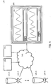
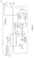
- FIG. 1 shows computer system 160 for controlling, detecting, controlling and / or analyzing biological, biochemical, chemical and / or physical processes.
- the computer system 160 shown includes multiple, but at least two units 135A to 135N (135 AN) configured to receive matter to perform at least one biological, biochemical, chemical, and / or physical process on that substance.
- Each of the units 135 AN has at least one sensor 140A to 140N (140 AN) configured to acquire measurement data relating to the process.
- the computer system 160 includes at least one display unit 100, via which the measurement data of the units 135 AN are respectively represented in a temporal correlation, which allows conclusions about a relationship between the measurement data presented.
- the measurement data of the respective units 135 AN can be displayed in separate display areas 105, 110.
- the user can use the display unit 100 with the aid of a respective slide controller 125, 130 to apply a time window via the corresponding zoom bars 113, 120 to the measured data of the respective batches, so that the course of the measured data starts from the respective time window be output via the display unit 100 regardless of an absolute time of the measurement data.
- computer system 160 may be configured to control, acquire, control, and / or analyze biological, biochemical, chemical, and / or physical processes as a Supervisory Control and Data Acquisition (SCADA) system.
- SCADA Supervisory Control and Data Acquisition
- a technical process can be computer monitored, controlled and / or regulated.
- Every layer has to fulfill a specific task within the communication between two systems.
- functions and protocols are defined that must fulfill specific tasks in the communication between two systems.
- communication or data flow passes through all 7 layers of the OSI layer model twice. Once at the transmitter and once at the receiver. Depending on how many intermediate stations the communication path has, the communication also passes through the layer model several times. Protocols in this context are a collection of rules for communication on a particular layer of the OSI model.
- the terminals of the end systems and the transmission medium are excluded from the OSI model. However, the terminals in the application layer and the transmission medium in the physical layer may be predetermined.
- the protocols of a layer are largely transparent, in particular to the protocols of the superordinate and subordinate layers, so that the mode of behavior of a protocol is as in direct communication with its counterpart on the other side.
- the transitions between the layers may in particular be interfaces that must be understood by the protocols. Because some protocols are designed for very specific applications, it is also possible for protocols to span multiple layers and cover multiple tasks. It may even be that in some connections individual tasks are performed multiple times.
- SCADA usually refers to central / distributed systems that monitor, visualize, and / or control entire installations. Most of the control is done automatically by Remote Terminal Units (RTUs) or Programmable Logic Controllers (PLCs) or Level 1 automations.
- RTUs Remote Terminal Units
- PLCs Programmable Logic Controllers
- Level 2 automation is to optimize the function of Level 1 automation as well as to output manipulated variables and / or setpoints.
- Level 3 automation is used for planning, quality assurance and / or documentation.
- the communication within a SCADA system can be based on TCP-based Internet techniques, whereby one or more serial connections in the form of point-to-point communications and / or fieldbus systems are possible.
- Level 1 Data collection usually begins with Level 1 and includes the coupling to gauges and status information such as switch positions detected by the SCADA system. The data is then presented in a user-friendly presentation, allowing control to intervene in the process.
- SCADA systems typically implement a distributed database that includes data points.
- a data point contains an input or output value that is monitored and / or controlled by the system.
- Data points can be calculated physically.
- a physical data point represents an input or output, while a calculated point results from the state of the system through mathematical operations.
- data points are treated as a combination of timestamped values.
- a series of data points allows the historical evaluation.
- the temporal correlation of data points from different units 135 A-N can advantageously be used to detect relationships of the corresponding data points or measurement data. This advantageously enables a user to influence the process (s) appropriately, e.g., by displaying the measurement data in a time-correlated manner. by setting corresponding process parameters, triggering specific processes or similar
- Each temporal correlation comprises a horizontal shifting or alignment of the measurement data of the respective units 135 A-N, so that the measurement data can be arbitrarily related to one another.
- a unit 135 AN or unit or unit includes in particular at least one reactor, eg at least one bioreactor and / or at least one chemical reactor, at least one sensor 140 AN and optionally one or more control modules and process units.
- Each unit AN may in its entirety represent, logically, a part of a production site, eg in a yeast-cultivating production plant, in which one or more process activities may be performed.
- Each unit 135 AN generates from the measurement data, the be detected by the sensor 140 AN and optionally by control modules at a given time, preferably only one batch.
- Each unit 135 AN may act independently of any other unit 135 AN.
- each unit 135 AN can be imaged with each unit 135 AN, so that all measurement data required for a process recording or process monitoring can be detected by means of at least one sensor 140 AN and displayed at the same time.
- Each unit 135 AN can be assembled individually according to a specific process, depending on the required process, from any combination of the above-mentioned components.
- a unit 135 AN may comprise in particular at least one filter which can be used for the filtration of a medium.
- it may be a filter for cross-flow filtration or tangential flow filtration or cross-flow filtration, in which liquids are filtered, for example, for the food and / or pharmaceutical industry.
- a suspension to be filtered is pumped at high speed parallel to a membrane or a filter medium, wherein a solid or permeate is withdrawn transversely to the flow direction.
- the cross-flow filtration can be used for example in microfiltration, ultrafiltration, nanofiltration, gas separation, pervaporation and / or reverse osmosis.
- Each of these units 135 AN comprises at least one sensor 140 AN and optionally one or more individual control units and process devices.
- Each unit 135 AN in its entirety, may logically represent part of a production facility, eg, a water treatment plant for the removal of heavy metals in the water treatment, in which one or more process activities may be performed.
- Each unit 135 AN generates from measured data, which are detected by the sensor 140 AN and optionally the control modules at a given time, preferably only one batch.
- Each unit 135 AN may act independently of any other unit 135 AN.
- each unit 135 AN a specific process can be mapped, so that all measurement data required for a process recording or process monitoring can be detected by means of at least one sensor 140 AN and displayed at the same time.
- Each unit 135 AN can according to a specific process according to the required process from any combination of the above Components to be put together.
- a sensor 140 AN is in particular a technical component which can quantitatively detect certain biological, biochemical, chemical and / or physical properties of its environment as a measured variable.
- the biological, biochemical, chemical and / or physical properties are converted into an electrical and / or optical signal.
- the electrical signal can then be sampled.
- a numerical measurement datum or a numerical measured value can be generated.
- the sensor 140 AN can create a data stream of the corresponding measurement data.
- Each unit 135 AN has in particular at least one sensor 140 AN, which is set up to detect specific, ie predetermined or predeterminable, measurement data relating to the process.
- it can be a gas sensor, for example an O 2 or CO 2 sensor, a pH sensor, a glucose sensor, a lactate sensor and / or any combination of the sensors, the or the are set up to detect a suitable measure in terms of the process to be performed.
- each unit 135 AN may also have one or more individual control units.
- a bioreactor 225 as a particular embodiment of a unit 135 AN (as discussed below with reference to FIGS FIG. 2
- a container which is set up to cultivate or ferment cells, microorganisms and / or small plants is described.
- biological processes for example bioconversion or biocatalysis, are used or made available in technical facilities. In doing so, an attempt is made to achieve the best possible cultivation conditions by means of important factors that can be controlled or controlled in the bioreactor 225.
- Controllable factors may be eg a composition of a nutrient solution or a substrate, an oxygen supply, a sterility or a pH.
- the purpose of culture in the bioreactor 225 may be recovery of cells, recovery of cellular components, or recovery of metabolites, which may then be used, for example, as a Active ingredient in the pharmaceutical industry or basic chemical can be used in the chemical industry.
- bioreactors are, for example, autoclavable bioreactors, in-situ sterilizable bioreactors, disposable bioreactors, stirred tank reactors, fixed bed reactors or photobioreactors.
- the production of alcoholic or alcoholic beverages, such as beer can take place in bioreactors, such as a brewing kettle.
- bioreactors are not subject to any specific restrictions.
- bioreactors for culturing cells such as bacterial, yeast, insect, plant or mammalian cells
- Bioreactors for producing metabolic products of such cells Bioreactors for the production of peptides or proteins expressed by such cells
- Bioreactors for the production of energy with the aid of such cells Bioreactors for the propagation of viruses by means of such cells
- Bioreactors for the degradation of substances by means of such cells Bioreactors for the production of foodstuffs with the aid of such cells
- Bioreactors for the production of biogas with the aid of such cells and combinations thereof.
- a control module 325 or control module (as described below with reference to FIG. 3 in particular includes variables that belong together to a physically measured or calculated size.
- the control module can also control or regulate the variables.
- Different types of control modules can be provided: Controller, Process Variable, Digital Variable and / or Offline Variable.
- a device 205, 210, 215 (as discussed below with respect to FIG. 2
- a sensor device 205 can represent an interface for the coupling of an O 2 / CO 2 analysis sensor to the unit.
- a reactor device 210 may represent an interface for the coupling of a bioreactor 225.
- a controller unit 215 may represent an interface for coupling a scale to the unit.
- a batch is a collection of data or data records which are acquired by the respective components of a unit within a specific, ie predetermined or predeterminable, period of time as measurement data.
- a batch is a record of measurement data about the process, which is carried out by the respective unit and can thus also be archived.
- Each batch can be stored in a database after the process has finished. So this can be used again and again for an analysis and / or evaluation. Thus each batch always contains the characteristic and temporally same process flows.
- the data or data records can be stored chronologically in the order in which they are combined in succession and displayed via the output unit.
- each batch may contain all the measurement data which, in the period between a filling of a unit, for example a reactor or bioreactor, be detected until a complete emptying of this unit after a specific, ie predetermined or predeterminable, time period, for example, a reaction time or growth time.
- a unit for example a reactor or bioreactor
- Measurement data or process data are, in particular, data or data records which contain information about a value of a property at a given time. Measurement data can be stored in a database.
- a substance may in particular be a liquid, a gas and / or a solid.
- the fabric may be composed of at least one component needed to facilitate the process.
- it may be useful for culturing certain organisms, e.g. Cells or certain parts of organisms, be necessary to create and maintain important conditions that ensure optimal growth of the organisms.
- such important conditions may be a composition of a nutrient medium or a substrate, an oxygen supply, a pH and / or a sterility in the bioreactor.
- Purpose of cultivation may include recovery of organisms, e.g. Cells and parts of organisms.
- Another purpose of culturing may be recovery of metabolites used as an active ingredient in the pharmaceutical industry and / or as a basic chemical in the chemical industry. Further, the purpose may be degradation of chemical compounds in e.g. Sewage treatment plants or to make a production of alcoholic beverages.
- the measurement data 335 (as discussed below with reference to FIG. 3 described) can be displayed via the display unit 100, for example in the form of waveforms.
- the measurement data may be presented in the form of one or more diagrams, eg pie charts, line charts, bar charts, organigrams, Gantt charts, flow charts, cause-and-effect diagrams, and / or block diagrams.
- the individual components of computer system 160 may be interconnected via a suitable network 145, eg, a "local area network” (LAN) or a “wide area network” (WAN).
- a suitable network 145 eg, a "local area network” (LAN) or a “wide area network” (WAN).
- the computer system 160 may include a detection unit 150 configured to automatically detect the temporal correlation.
- the detection unit 150 may compare a course of the measurement data of the respective units 135 A-N with each other and display measurement data that corresponds to each other independent of an absolute time of their detection in a corresponding manner over the display unit 100 in the respective display areas 105, 110.
- a user may use a suitable input device, such as a mouse.
- a keyboard or a keyboard and / or a computer mouse set a marker in a displayed measurement data history. On the basis of this marker, a temporal correlation of the measured data can be detected.
- each batch can be divided into different phases.
- a first phase may correspond to filling a matter into a unit
- a second phase may correspond to adding cells to the matter
- a third phase may be to adding more cells to the matter, and so forth.
- a temporal correlation of the measured data can be detected by measuring data of different units corresponding to a beginning of a specific phase.
- the computer system 160 may include a control module 155 configured to group at least two units 135 AN together so that the group may be simultaneously controlled via the control module 155 (as discussed below with reference to FIGS FIG. 4 illustrated).
- the computer system 160 in particular has the advantage that effects of different important process factors or a change of one or more such process factors can be detected in a simple and efficient manner in real time.
- a continuous optimization or improvement of the processes is made possible.
- this achieves an improved, continuous user-machine interaction, since an adjustment of biological, chemical, biochemical and / or physical process parameters during ongoing processes in the respective units 135 AN is intentionally set and / or entered depending on the corresponding state of the process can be.
- This allows coordination or coordination of the technical processes in the respective units 135 A-N.
- an alarm can be displayed via the display unit 100 if the conditions important for the respective biological, biochemical, chemical and / or physical process are exceeded or undershot, e.g. at too low or too high oxygen content and / or pH in the matter that is in the reactor.
- Another advantage is that relevant technical relationships of the processes in the respective units 135 A-N can be made accessible via the display unit 100 independently of an absolute time of the acquired measurement data via the temporal correlation.
- the temporal correlation over the duration of the processes in the respective units 135 A-N can be maintained.
- a user is enabled to more efficiently and more quickly master the technical tasks of monitoring technical parameters, controlling technical process parameters, detecting technical relationships of the various processes, and monitoring the effects of various technical parameters on a process flow in the respective 135A-N units.
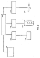
- FIG. 2 12 shows a block diagram of an exemplary unit 200.
- the unit 200 includes a reactor 225 or a filter configured to receive a matter to perform at least one biological, biochemical, chemical, and / or physical process on that substance.
- the unit 200 comprises a sensor 220, for example an O 2 / CO 2 analyzer, which is set up to acquire measurement data relating to the process.
- the unit 200 comprises a control unit 230, for example a balance and / or one or more internal control units 235. Each of the internal control units 235 may be configured to perform calculations on the acquired measurement data and / or samples of the substance on which the process is performed is to be taken and / or analyzed.
- Each of these components can be coupled to the unit 200 via a corresponding device 205, 210, 215.
- Each device 205, 210, 215 may be a communication interface or communication interface.
- the separation between units 200 and devices 205, 210, 215 has the advantage that a configuration of a unit 200 can be performed in a simple and efficient manner, since the respective components 220, 225, 230 are used with the aid of the devices 205, 210, 215 can be connected to the unit 200.
- the O 2 / CO 2 analyzer 220 is coupled to the unit 200 via a Universal Serial Bus (USB) connection, with a sensor device 205 serving as the communication interface.
- USB Universal Serial Bus
- the bioreactor 225 can, for example, transmit corresponding measurement data to the unit 200 via Ethernet and / or exchange further data with the unit 200, with a reactor device 210 serving as the communication interface for this purpose.
- the balance 230 may be coupled to the unit 200 with a control module device 215.
- required internal control modules 235 may be coupled to the unit 200.
- Each control module variable can be assigned its own MappingShortID. This has the advantage that the measurement data arriving in accordance with it can be unambiguously assigned to a control module variable.
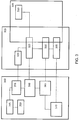
- FIG. 3 shows an overview of an exemplary structure and relationships of measurement data 335 of a unit 320, which are combined into a batch 350.
- a device 310 can communicate with each unit 320 via a control module 325.
- Each control module 325 may include control module variables 330.
- a control module may be a collection of variables and / or values belonging to a physical quantity.
- Each control module has at least one value (eg 34.5), one unit. (eg ° C), a unit and a "source" (a device from which the values or a calculation of the values originate).
- a control module can contain additional variables (eg setpoint, manipulated variable and / or low limit or alarm limit).
- a look at the measured data 335 is possible. From the user view 315 or monitoring view, each control module 325 is assigned to a unit 320 and can have one or more control module variables 330.
- control module variables can be displayed, but not all, but only the type of actual value, setpoint and / or manipulated variable.
- Each of these control module variables 330 may be assigned one or more measurement data 335.
- the user view shows a currently valid configuration of a unit 320.
- One Control module can have several variables depending on the type. However, only one measurement datum / measured value can be assigned to each variable.
- each batch 345 is assigned a start and stop time 350.
- the batch start time corresponds to the recording start and at the same time the associated biological / chemical process start on the unit.
- the batch stop time corresponds to a corresponding biological / chemical process end and at the same time to the end of recording.
- the control modules 325 configured during the batch start, their control module variables 330 and the measurement data 335 accumulating during the process are likewise stored in the batch 345.
- each batch 345 stores a snapshot of the currently valid configuration as well as all measurement data or process data.
- the computer system 160 allows administration of an already new / different / changed configuration (new or changed devices on the device, renamed device, changed ControlModule names, deleted device) of the respective devices 205, 210, 215.
- a monitoring of the measurement data or process data to a unit 320 is made possible.
- the communication view allows a display of a flow of measured data as well as an assignment of the measured data.
- the batches 345 and their associated process data can be stored in a database.
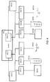
- a detection unit 150 in the computer system 160 indicate the temporal correlation by uniting two units 135 AN into a group 400 (unit grouping).
- FIG. 4 shows an example of a group 400 of at least two units 405 AN.
- the units 405 are AN or units of the same type or have the same sensors 420 AN or individual control units 430A-N.
- the connection of the respective components to the respective units 405 AN takes place analogously to the connection as described above with reference to FIG. 2
- the sensors 420 AN are connected to the respective unit 405 AN by means of a respective sensor device 406 AN.
- the reactors 410 AN can be coupled to the respective unit 405 AN by means of corresponding reactor devices 410 AN.
- the individual control units 430 AN can be coupled to the respective unit 405 AN by means of corresponding individual control devices 415 AN.
- the respective internal control modules 435 AN may be coupled to the respective units 405 AN become.
- the measurement data of the respective batches can be output via the display unit 100 using the display unit 100 either in a common display area or optionally in separate display areas.
- a group 400 may be created from an arbitrary combination of the units 405 A-N to be time correlated.
- each user has the option of taking a snapshot of the measurement data, which are displayed in a time-correlated manner via the display unit 100, by inputting a corresponding command, e.g.
- Each group 400 may also automatically during running processes, e.g. by having a specific, i. predetermined or predeterminable, condition is met, or manually resolved by the user.
- measurement data of the respective sensor are combined into a separate batch via the respective process of the reactor and / or filter and optionally the respective additional control modules and internal control modules and displayed via the display unit 100.
- the computer system 160 may include a default according to which the display unit 100 always uses the most recent ones N data or records that have been recorded and added to the batch are displayed, where N is a specific, ie predetermined or predeterminable, number of data or records defined.
- the temporal correlation can be displayed by choosing a time window specific, ie predetermined or predeterminable magnitude is applied to the measurement data of the respective units 405 AN such that measurement data located in the time window are displayed time-correlated independent of an absolute time of their acquisition.
- This temporal correlation or synchronization of the measurement data can be retained in the display unit 100, even if new measurement data is recorded in the batch.
- the display unit 100 may represent the temporal correlation of the data that is within the time window.
- the synchronization is a special type of temporal correlation, since measurement data that are changed in a display area or display window in size relative to measurement data that are displayed in a second display area or display window, in particular upsets or be stretched.
- the temporal correlation may be displayed by correlating measurement data, measured by sensors of the respective units 405 AN at different time intervals, with each other in temporal correlation.
- the size of the time window which is applied to the respective batch can be adapted such that the measured data correspond in their time intervals.
- the temporal correlation can be set manually by a user.
- FIG. 5 1 shows an exemplary, simplified display of a display unit 500, in which a first slider 525 is present in the upper display area 505, which can be moved via a first zoom bar 515.
- a time window can be applied to the measurement data 335 of a first batch, also referred to below as trend. Since the first slider 525 does not abut on the right edge, the upper trend indicates the measurement data of the batch from the selected time window regardless of an absolute time of detection of the measurement data 335.
- measurement data 335 becomes another unit displayed, wherein a second slider 530 can be moved via a second zoom bar 520. In this case, synchronization of the measurement data of both units is not possible because the total time span of the two trends is too different.
- a user may specify a width of the time window, i. controlling a number of measurement data 335 to be displayed by using a suitable input device to drive a point on the zoom bar 515, 520 located outside the thumb.
- a suitable input device to drive a point on the zoom bar 515, 520 located outside the thumb.
- FIG. 6 shows an example of a partially possible action.
- FIG. 6 via the display unit 600 in a first display area 605 a first measurement data trend or trend.
- the slider 625 is located at the far left of the zoom bar 615. This may mean, for example, that the first measurement data 335 of the corresponding batch 345 is displayed.
- a second display area 610 a second measurement data profile is displayed, wherein the slider 630 is located on the far right of the corresponding zoom bar 620.
- the two trends can be linked together using a corresponding button 635.
- FIG. 7 shows two measured data profiles or, in which a synchronization of the time axis is possible, wherein FIG. 8 shows the result of the synchronization of the time axes.
- FIG. 7 a display unit 700, which displays a first measurement data course of a first unit 135 AN, 200, 320 in a first display area 705 and a second measurement data course of a second unit 135 AN, 200, 320 in a second display area 710.
- the respective sliders 725, 730 have the same size and are in the same area of the respective zoom bar 715, 720.
- the two measured data profiles can be synchronized by activating a corresponding button 740.
- the technical realization will be discussed below with reference to FIG. 9 explained.
- FIG. 8 shows the two measured data curves as in FIG. 7 after synchronization due to activation of the button 740 (FIG. FIG. 7 ) has been activated.
- the deflections or changes of the respective measurement data in the respective display areas 805, 810 are now displayed synchronously with one another, ie in mutually equal or similar distances.
- the relative size of the slider of the second display unit 830 has decreased, so that fewer measurement data are displayed in the corresponding display area 810 in order to enable the synchronized representation of the measurement data. It depends on which batch has been running for some time. So it is quite possible that the lower or the upper trend or its zoom bar is reduced.
- a command "SynchTrendsCommand” can be stored in a class “TrendDisplay”, i. a Model View ViewModel (MWM) of the trend to be implemented.
- MWM is a variant of the Model View Controller Pattern (MVC) that separates user interface and user interface (UI) representation and logic, and is supported by the UI platform WPF.
- MVC Model View Controller Pattern
- An exemplary system includes a universal computing device in the form of a conventional computing environment 20, such as a personal computer (PC) 20, having a processor unit 22, a system memory 24, and a system bus 26 containing a variety of system components, including system memory 24 and the processor unit 22 connects.
- the processor unit 22 may perform arithmetic, logic and / or control operations by accessing the system memory 24.
- the system memory 24 may store information and / or instructions for use in combination with the processor unit 22.
- System memory 24 may include volatile and non-volatile memory, such as random access memory (RAM) 28 and read-only memory (ROM) 30 include.
- a basic input-output system (BIOS) containing the basic routines that help to transfer information between the elements within the personal computer 20, for example, during start-up, may be stored in the ROM 30.
- the system bus 26 may be one of many bus structures, including a memory bus or memory controller, a peripheral bus, and a local bus employing a particular bus architecture from a variety of bus architectures.
- the PC 20 may further include a hard disk drive 32 for reading or writing a hard disk (not shown) and an external disk drive 34 for reading or writing a removable disk 36 or a removable medium.
- the removable disk may be a magnetic disk for a magnetic disk drive or an optical disk such as a floppy disk. a CD-ROM, for an optical disk drive.
- the hard disk drive 32 and the external disk drive 34 are each connected to the system bus 26 via a hard disk drive interface 38 and a disk drive interface 40.
- the drives and associated computer-readable media provide nonvolatile storage of computer readable instructions, data structures, program modules, and other data to the PC 20.
- the data structures may include the relevant data for implementing a method as described above.
- the exemplary environment utilizes a hard disk (not shown) and an external disk 42, it will be apparent to those skilled in the art that other types of computer-readable media that can store computer-accessible data may be used in the exemplary work environment, such as a computer. magnetic cassettes, flash memory cards, digital video disks, random access memory, read-only memory, etc.
- a plurality of program modules in particular an operating system (not shown), one or more application programs 44 or program modules (not shown) and program data 46 may be stored on the hard disk, the external disk 42, the ROM 30 or the RAM 28 ,
- the application programs can perform at least some of the functionality, as in FIG. 1 respectively.
- FIGS. 5 to 9 shown include.
- a user may enter commands and information as described above into the PC 20 by means of input devices, e.g. a keyboard 48 and a computer mouse 50.
- Other input devices may include a microphone and / or other sensors, a joystick, a game pad, a scanner, or the like.
- These or other input devices may be connected to the processor unit 22 via a serial interface 52 which is coupled to the system bus 26 or may be interfaced with other interfaces, such as e.g. a parallel interface 54, a game port or a universal serial bus (USB).
- a printer 56 The printer 56 and other parallel input / output devices may be connected to the processor unit 22 through the parallel interface 54.
- a monitor 58 or other type of display device (s) is / are connected to the system bus 26 by means of an interface, such as e.g. a video input / output 60.
- the computing environment 20 may include other peripheral output devices (not shown), e.g. Speaker or acoustic outputs include.
- the computing environment 20 may communicate with other electronic devices, such as a computer, a corded phone, a cordless phone, a personal digital assistant (PDA), a television, or the like. To communicate, the computing environment 20 may operate in a networked environment using connections to one or more electronic devices.
- FIG. 11 illustrates the computing environment networked with a remote computer 62.
- the remote computer 62 may be another computing environment, such as a server, router, network PC, peer device, or other common computing environment Network node and may include many or all of the elements described above with respect to the computing environment 20.
- the logical connections, as in FIG. 11 include a local area network (LAN) 64 and a wide area network (WAN) 66.
- LAN local area network
- WAN wide area network
- Such networking environments are commonplace in offices, corporate-wide computer networks, intranets, and the Internet.
- the computing environment 20 When a computing environment 20 is used in a LAN network environment, the computing environment 20 may be connected to the LAN 64 through a network input / output 68.
- the computing environment 20 When the computing environment 20 is used in a WAN networking environment, the computing environment 20 may include a modem 70 or other means of establishing communication over the WAN 66.
- the modem 70 which may be internal and external to the computing environment 20, is connected to the system bus 26 via the serial interface 52.
- program modules that are relative to the computing environment 20, or portions thereof may be stored in a remote storage device that is accessible to or from a remote computer 62.
- other data relevant to the method or system described above may be accessible on or from the remote computer 62.
Description
Die vorliegende Erfindung betrifft ein Computersystem, ein computer-implementiertes Verfahren, ein Computerprogrammprodukt sowie eine Benutzerschnittstelle zur Steuerung, Erfassung, Regelung und/oder Analyse von biologischen, biochemischen, chemischen und/oder physikalischen Prozessen.The present invention relates to a computer system, a computer-implemented method, a computer program product and a user interface for controlling, detecting, regulating and / or analyzing biological, biochemical, chemical and / or physical processes.
Beispielsweise ist aus der
Bekannte Systeme ermöglichen eine Anzeige von Messdaten in Echtzeit, die über einen Sensor einer Einheit erfasst werden, d.h. die Messdaten, welche angezeigt werden, sind an eine aktuelle Prozesszeit gekoppelt. Eine Anzeige von Messdaten unabhängig von einer absoluten Zeit ihrer Erfassung ist nicht möglich. Die Anzeige erfolgt über eine Anzeigeeinheit, welche an einen Bioreaktor bzw. eine Filtrationsanlage bzw. ein Einfrier-und Auftau-System gekoppelt ist. Ferner ist es konventionell möglich, Parameter, die für die Durchführung eines biologischen, biochemischen, chemischen und/oder physikalischen Prozesses bedeutsam sind, über die Anzeigeeinheit einzustellen. Bei den Parametern kann es sich zum Beispiel um einen pH-Wert, eine Sauerstoffzufuhr, etc. handeln. Dadurch wird eine prozessnahe Visualisierung von Messdaten sowie eine Steuerung von Prozessparametern ermöglicht.Known systems allow real-time measurement data to be displayed via a sensor of a unit, ie the measurement data that is displayed is coupled to a current process time. A display of measured data independent of an absolute time of their detection is not possible. The display is made via a display unit, which is coupled to a bioreactor or a filtration system or a freezing and thawing system. Furthermore, it is conventionally possible to set parameters that are important for carrying out a biological, biochemical, chemical and / or physical process via the display unit. The parameters may be, for example, a pH, an oxygen supply, etc. This enables process-oriented visualization of measurement data as well as control of process parameters.
Allerdings ist es bei einer Durchführung von biologischen, biochemischen, chemischen und/oder physikalischen Prozessen in einer Einheit, welche einen Reaktor beinhaltet, von wesentlicher Bedeutung, einen genauen Überblick über wichtige, den Prozess beeinflussende Faktoren sowie eine Auswirkung einer Änderung dieser Faktoren auf den Prozesserfolg zu erhalten. Aus diesem Grund ist es notwendig, einen Verlauf von Messdaten, die z.B. innerhalb ein oder mehrerer Batch-Phasen bzw. Batches unterschiedlicher Prozesse, unterschiedlicher Prozessausgestaltungen und/oder von gleichen und/oder unterschiedlich ausgestalteten Prozessen, die zu verschiedenen absoluten Zeitpunkten gestartet wurden, miteinander zu vergleichen. Konventionelle Systeme ermöglichen es nicht, solch einen Messdatenverlauf in einer zeitlichen Korrelation derart darzustellen, um Aufschlüsse über einen Zusammenhang der erfassten Messdaten zu ermöglichen.However, carrying out biological, biochemical, chemical and / or physical processes in a unit incorporating a reactor is of essential importance, a close overview of important factors affecting the process and an effect of changing these factors on the process success to obtain. For this reason, it is necessary, a course of measurement data, for example, within one or more batch phases or batches of different processes, different process designs and / or of the same and / or differently configured processes, the different absolute times were started to compare. Conventional systems do not make it possible to present such a measurement data history in a temporal correlation in such a way as to provide information about a relationship of the acquired measurement data.
Aufgabe der vorliegenden Erfindung ist es demnach, Messdaten von biologischen, biochemischen, chemischen und/oder physikalische Prozesse in verbesserter Weise zu erfassen und weiterverarbeiten zu können.It is therefore an object of the present invention to be able to record and further process measurement data of biological, biochemical, chemical and / or physical processes in an improved manner.
Diese Aufgabe wird erfindungsgemäß durch die Merkmale der unabhängigen Ansprüche gelöst. Bevorzugte Ausführungsformen sind Gegenstand der abhängigen Ansprüche.This object is achieved by the features of the independent claims. Preferred embodiments are subject of the dependent claims.
Gemäß eines ersten Aspekts der Erfindung wird das Computersystem zur Steuerung, Erfassung, Regelung und/oder Analyse von biologischen, biochemischen, chemischen und/oder physikalischen Prozessen gemäß Anspruch 1 bereitgestellt, welches umfasst:
- zumindest zwei Einheiten bzw. Units, welche eingerichtet sind, einen Stoff bzw. eine Materie aufzunehmen, um an diesem Stoff zumindest einen biologischen, biochemischen, chemischen und/oder physikalischen Prozess durchzuführen;
- wobei jede der Einheiten zumindest einen Sensor aufweist, welcher eingerichtet ist, Messdaten betreffend den Prozess zu erfassen; und
- zumindest eine Anzeigeeinheit, über welche die Messdaten der zwei Einheiten jeweils in einer zeitlichen Korrelation dargestellt werden, welche Aufschlüsse über einen Zusammenhang der dargestellten Messdaten ermöglicht.
- at least two units or units which are set up to receive a substance or matter in order to carry out at least one biological, biochemical, chemical and / or physical process on this substance;
- each of the units comprising at least one sensor configured to acquire measurement data relating to the process; and
- at least one display unit, via which the measurement data of the two units are each represented in a temporal correlation, which allows conclusions about a relationship of the measured data shown.
Ein Reaktor kann z.B. ein Bioreaktor und/oder ein chemischer Reaktor sein, welcher eingerichtet ist, einen Stoff bzw. eine Materie aufzunehmen, an der zumindest ein biologischer, biochemischer, chemischer und/oder physikalischer Prozess durchgeführt werden kann. Bei den Bioreaktoren können sowohl single-use Reaktoren in Form von Beuteln oder Standgeräten als auch feste Behälter aus Edelstahl zum Einsatz kommen. Je nach Art der Kultivierung sind die Bioreaktoren mit festen Materialen zur Ansiedelung adhärenter Zellen gepackt oder als Rührreaktor ausgestaltet.A reactor may, for example, be a bioreactor and / or a chemical reactor which is set up to receive a substance or matter on which at least one biological, biochemical, chemical and / or physical process can be carried out. The bioreactors can be either single-use reactors in the form of bags or stationary devices as well as solid containers made of stainless steel used. Depending on the type of cultivation, the bioreactors are packed with solid materials for the attachment of adherent cells or designed as a stirred reactor.
Alternativ oder zusätzlich zum Reaktor kann eine Einheit insbesondere zumindest einen Filter beinhalten, welcher zur Filtration eines Mediums verwendet werden kann. Beispielsweise kann es sich dabei um einen Filter zur Cross-Flow-Filtration handeln, welcher z.B. zur Reinigung und/oder Abtrennung von Proteinen oder Proteinbestandteilen verwendet werden kann; einen Filter zur Durchführung einer Membranchromatographie, z.B. zur Abtrennung von Zellbestandteilen, Nukleinsäuren, Viren, Mycoplasmen oder Endotoxinen; einen Clarification-Filter, z.B. zur Aufreinigung von Serum- bzw. Plasmalösung; einen Virenfilter, z.B. zur Abtrennung von Viren und/oder Virenbestandteilen; ein UV-C Inaktivierungssystem, z.B. zur Abtrennung von Viren und/oder Virenbestandteilen; und/oder einen Tangential-Flow-Filter bzw. Querstromfilter zur Filtration von Flüssigkeiten, beispielsweise in der Lebensmittel-und/oder Pharmaindustrie.As an alternative or in addition to the reactor, a unit may in particular include at least one filter which can be used for the filtration of a medium. For example, this may be a filter for cross-flow filtration, which may be e.g. can be used for the purification and / or separation of proteins or protein components; a filter for performing a membrane chromatography, e.g. for the separation of cell components, nucleic acids, viruses, mycoplasma or endotoxins; a clarification filter, e.g. for purification of serum or plasma solution; a virus filter, e.g. for the separation of viruses and / or viral components; a UV-C inactivation system, e.g. for the separation of viruses and / or viral components; and / or a tangential flow filter or cross-flow filter for the filtration of liquids, for example in the food and / or pharmaceutical industry.
Alternativ oder zusätzlich zum Reaktor bzw. Filter kann eine Einheit insbesondere zumindest ein Einfrier-und Auftau-System beinhalten, welches beispielsweise eingerichtet ist, bio-pharmazeutische Flüssigkeiten in einer Herstellung und Prozessentwicklung reproduzierbar einzufrieren und aufzutauen.Alternatively or in addition to the reactor or filter, a unit may in particular include at least one freezing and thawing system, which is set up, for example, to reproducibly freeze and thaw bio-pharmaceutical liquids in a production and process development.
Bei dem Stoff kann es sich um eine Flüssigkeit, ein Gas und/oder einen Feststoff handeln. Der Stoff kann sich aus zumindest einer Komponente zusammensetzen, welche benötigt wird, um die Durchführung des Prozesses zu ermöglichen. So ist es beispielsweise zur Kultivierung von Mikroorganismen notwendig, wesentliche Bedingungen, die ein optimales Wachstum der Organismen gewährleisten, zu schaffen und aufrechtzuerhalten. Beispielsweise kann es sich bei solchen wichtigen Bedingungen um eine Zusammensetzung eines Nährmediums oder einer Nährlösung t, eines Sauerstoffgehaltes, eines pH-Wertes und/oder einer Temperatur im Bioreaktor handeln. Zweck der Kultivierung kann letztendlich die Gewinnung der Organismen oder Teilen der Organsimen und/oder deren sezernierten oder unsezernierten Stoffwechselprodukte, sein, welche als Wirkstoff in der pharmazeutischen Industrie oder als Grundchemikalie in der chemischen Industrie verwendet werden können. Ferner kann es sich beim Zweck der Kultivierung um einen Abbau chemischer Verbindungen, z.B. in Kläranlagen oder zur Fermentation von Lebensmittels handeln.The substance may be a liquid, a gas and / or a solid. The fabric may be composed of at least one component needed to facilitate the process. For example, to cultivate microorganisms, it is necessary to create and maintain key conditions that ensure optimal growth of the organisms. For example, such important conditions may be a composition of a nutrient medium or a nutrient solution t, an oxygen content, a pH and / or a temperature in the bioreactor. The purpose of culturing may ultimately be recovery of the organisms or parts of the organisms and / or their secreted or unsecreted metabolites, which may be used as an active ingredient in the pharmaceutical industry or as a basic chemical in the chemical industry. Furthermore, the purpose of cultivation may be degradation of chemical compounds, eg in sewage treatment plants or for fermentation of food.
Jede Einheit kann dabei individuell aus zumindest einem Reaktor, zumindest einem Sensor sowie optional ein oder mehreren Einzelsteuereinheiten und Prozessgeräten zusammengesetzt werden, die in ihrer Gemeinsamkeit aus logischer Sicht einen Teil eines Werkes darstellen, in welchem ein oder mehrere Prozessaktivitäten durchgeführt werden können. Jede Einheit generiert zu einem gegeben Zeitraum während eines Prozesses immer nur einen Batch. Somit kann mit jeder Einheit ein spezifischer Prozess abgebildet werden, so dass alle zu einer Prozessaufzeichnung bzw. Prozessüberwachung benötigten Messdaten mithilfe des Sensors erfasst und gleichzeitig angezeigt werden können.Each unit can be composed individually from at least one reactor, at least one sensor and optionally one or more control modules and process devices that represent in their commonality from a logical point of view, a part of a plant in which one or more process activities can be performed. Each unit generates only one batch at a given time during a process. Thus, a specific process can be mapped with each unit, so that all measurement data required for a process recording or process monitoring can be recorded by means of the sensor and displayed at the same time.
Messdaten von den in den Einheiten vorhandenen Stoffen und/oder darin ablaufenden Prozessen, welche mit dem Computersystem erfasst, dargestellt und gegebenenfalls mit Messdaten anderer Einheiten korreliert werden können, unterliegen keinen besonderen Einschränkungen und sind im hohen Maße von der jeweiligen Anwendung und deren Aufgabe oder Fragestellung abhängig. Sie können beispielsweise Zelldichte, Wachstumsrate der Zellen, Menge eines Kulturmediums, Schaumentwicklung des Kulturmediums, pH-Wert des Kulturmediums, Temperatur des Kulturmediums, Sauerstoffgehalt des Kulturmediums, Kohlendioxidgehalt des Kulturmediums, Trübung des Kulturmediums, Kapazität und/oder Leitfähigkeit des Kulturmediums, Konzentration bestimmter Inhalts- oder Nährstoffe des Kulturmediums, Konzentration hergestellter und sezernierter Stoffwechselprodukte, Peptide und/oder Proteine im Kulturmedium, Flussraten in bestimmten Teilen des Bioreaktors, oder Betriebsparameter des Bioreaktors betreffen. Entsprechende Sensoren zur Erfassung solcher oder anderer Messdaten unterliegen keinen besonderen Einschränkungen und sind im Stand der Technik bekannt. Messdaten können in einem spezifischen Zeitintervall erfasst werden. Vorzugsweise kann das Zeitintervall in einem Bereich zwischen etwa 500 bis etwa 60.000 ms liegen. Vorzugsweise können die Messdaten von jeder Einheit von dem Sensor abgerufen werden (Polling).Measurement data of the substances present in the units and / or processes running therein which can be recorded with the computer system, displayed and possibly correlated with measurement data of other units are not subject to any particular restrictions and are highly dependent on the respective application and its task or question dependent. They may be, for example, cell density, growth rate of the cells, amount of a culture medium, foaming of the culture medium, pH of the culture medium, temperature of the culture medium, oxygen content of the culture medium, carbon dioxide content of the culture medium, turbidity of the culture medium, capacity and / or conductivity of the culture medium, concentration of specific content or nutrients of the culture medium, concentration of produced and secreted metabolites, peptides and / or proteins in the culture medium, flow rates in certain parts of the bioreactor, or operating parameters of the bioreactor. Corresponding sensors for detecting such or other measurement data are not subject to any particular restrictions and are known in the prior art. Measurement data can be acquired in a specific time interval. Preferably, the time interval may be in a range between about 500 to about 60,000 ms. Preferably, the measurement data from each unit can be retrieved from the sensor (polling).
Im Beispiel einer durchzuführenden Fermentation kann sich eine Einheit aus einem Behälter (z.B. einem Bioreaktor, eine Filtrationsanlage oder ein Einfrier- und Auftausystem), einem Sensor (z.B. einem Gas-Analysegerät zur Analyse von O2 und/oder CO2) und einer weiteren Einzelsteuereinheit (z.B. einer Waage) zusammensetzen. Jede dieser Komponenten kann über ein entsprechendes Device an die Einheit gekoppelt sein. Jedes Device kann eine Kommunikationsschnittstelle bzw. Eingabe-/Ausgabe-Schnittstelle bzw. Communication Interface sein. Die Trennung zwischen Einheiten und Devices hat den Vorteil, dass eine Konfiguration einer Einheit, die sich aus zumindest einem Reaktor, zumindest einem Sensor sowie verschiedensten Einzelsteuereinheiten zusammensetzen kann, welche auf einfache und effiziente Weise mithilfe der Devices an eine Einheit, z.B. über ein Netzwerk, angebunden werden können, effizient und einfach realisieren lässt. Außerdem ist eine saubere Trennung zwischen Kommunikationssicht, technischer Sicht und Prozesssicht ermöglicht. So kann im vorangehenden Beispiel das Gas-Analysegerät über eine Universal Serial Bus (USB)-Verbindung an die Einheit gekoppelt werden, wobei ein Sensor Device als Kommunikationsschnittstelle dient. Der Bioreaktor kann beispielsweise via Ethernet Daten mit der Einheit austauschen, wobei ein Reaktor-Device als Kommunikationsschnittstelle dienen kann. Eine Waage kann über ein Einzelsteuereinheit-Device an die Einheit gekoppelt werden. Optional können benötigte interne Einzelsteuereinheiten an die Einheit gekoppelt werden. Beispielsweise kann ein Berechnungs-Modul eingesetzt werden, welches anstelle eines Devices zyklische Berechnungen durchführt und damit ähnlich wie ein Device zyklisch das Ergebnis als Wert an ein Control Module liefert. Ein Sample Data Management Modul kann die manuelle Eingabe von entnommenen Probedaten ermöglichen, welche im Labor erst aus einer Probe ermittelt wurden. Diese logische Zusammenfassung der jeweiligen Komponenten zu einer Einheit hat den Vorteil, dass eine Trennung zwischen der Gerätekommunikation (Devices) und einem Monitoring, also einer Prozessebene (Einheiten), erzielt wird.In the example of a fermentation to be carried out, a unit may consist of a container (eg a bioreactor, a filtration system or a freezing and thawing system), a sensor (eg a gas analyzer for the analysis of O 2 and / or CO 2 ) and a further control unit (eg a balance) put together. Each of these components can be coupled to the unit via a corresponding device. Each device can be a communication interface or input / output interface or communication interface. The separation between units and devices has the advantage that a configuration of a unit, which can be composed of at least one reactor, at least one sensor and a variety of control units, which in a simple and efficient manner using the devices to a unit, for example via a network, can be connected, implemented efficiently and simply. In addition, a clean separation between communication view, technical view and process view is possible. Thus, in the preceding example, the gas analyzer can be coupled to the unit via a Universal Serial Bus (USB) connection, with a Sensor Device serving as the communication interface. The bioreactor can exchange data with the unit via Ethernet, for example, whereby a reactor device can serve as a communication interface. A balance can be coupled to the unit via a control module device. Optionally, required internal control units can be coupled to the unit. For example, a calculation module can be used, which instead of a device performs cyclic calculations and thus similar to a device cyclically delivers the result as a value to a control module. A Sample Data Management module can enable the manual entry of sample data, which was determined in the laboratory only from a sample. This logical combination of the respective components into a unit has the advantage that a separation between the device communication (devices) and a monitoring, ie a process level (units), is achieved.
Jede Einheit weist zumindest einen Sensor auf, welcher eingerichtet ist, spezifische, d.h. vorbestimmte bzw. vorbestimmbare, Messdaten bezüglich des Prozesses zu erfassen. Beispielsweise kann es sich dabei um einen Gassensor, z.B. einen O2- bzw. CO2-Sauerstoffsensor, einen pH-Sensor, einen Glucose-Sensor, einen Lactat-Sensor sowie jeden anderen Sensor, der eingerichtet ist, eine geeignete Messgröße in Hinblick auf den durchzuführenden Prozess zu erfassen, oder auch um eine beliebige Kombination der Sensoren handeln. Optional kann jede Einheit zusätzlich zumindest eine Einzelsteuereinheit aufweisen. Entsprechendes gilt für Filtrationsanlagen. Die Trennung Unit/Devices dient dem modularen Aufbau mit dem sich jeder Benutzer seinen eigenen Prozess standardisiert zusammenkonfigurieren kann, ohne Engineering zu betreiben.Each unit has at least one sensor which is set up to detect specific, ie predetermined or predeterminable, measurement data relating to the process. For example, this may be a gas sensor, such as an O 2 - or CO 2 -Sauerstoffsenso r, a pH sensor, a glucose sensor, a lactate sensor and any other sensor which is arranged a suitable measured variable in regard to grasp the process to be performed, or to act on any combination of the sensors. Optionally, each unit can additionally have at least one individual control unit. The same applies to filtration systems. The Separation Unit / Devices serves the modular structure with which each user can configure his own process in a standardized way, without operating engineering.
Die Messdaten können über die Anzeigeeinheit, beispielsweise in Form von Messkurven, dargestellt werden. Alternativ dazu oder zusätzlich können die Messdaten in Form von ein oder mehreren Diagrammen, z.B. Kreisdiagrammen, Liniendiagrammen, Balkendiagrammen, Organigrammen, Gantt-Diagrammen, Fluss-Diagrammen, Ursache-Wirkungs-Diagrammen, Blockdiagrammen etc., dargestellt werden. Die Messdaten können z.B. vom Typ Float, Integer, Double, String oder Boolean sein.The measured data can be displayed via the display unit, for example in the form of measuring curves. Alternatively or additionally, the measurement data may be in the form of one or more diagrams, e.g. Pie charts, line charts, bar charts, organization charts, Gantt charts, flow charts, cause-and-effect diagrams, block diagrams, etc., are presented. The measurement data may e.g. of the type Float, Integer, Double, String or Boolean.
Die Messdaten können in einer Datenbank gespeichert werden, die geeignet ist, die gespeicherten Messdaten schnell und in kleinen zeitlichen Abständen auf einen entsprechenden Datenbankaufruf hin auszugeben. Beispielsweise kann in der Datenbank eine effiziente Datenkomprimierung implementiert sein.The measurement data can be stored in a database which is capable of outputting the stored measurement data quickly and in small time intervals to a corresponding database call. For example, efficient data compression may be implemented in the database.
Beispielsweise kann sich ein Messdatum aus folgenden Variablen zusammensetzen:
- MappingShortID → Identifizierung Kontrollmodul-Variable;
- Timestamp → Zeitstempel: Wann ist das Messdatum in der Einheit eingegangen?;
- Value → Messwert des Messdatums;
- Quality → binärer Wert, z.B. 0 für "good", 1 für "bad"; die Qualität kann ausschlaggebend dafür sein, ob das Messdatum über die Anzeigeeinheit angezeigt wird;
- Checksum bzw. Prüfsumme → Wird vom Computersystem generiert, um eine Datenmanipulation zu verhindern; dies hat den Vorteil, dass die Sicherheit im Computersystem erhöht wird.
- MappingShortID → Identification control module variable;
- Timestamp → Timestamp: When did the measurement date arrive in the unit ?;
- Value → measured value of the measuring date;
- Quality → binary value, eg 0 for "good", 1 for "bad"; the quality can determine whether the measurement date is displayed on the display unit;
- Checksum → Generated by the computer system to prevent data manipulation; This has the advantage of increasing security in the computer system.
Um den Prozess der Kultivierung der Zellen zu optimieren, ist es wesentlich, einen genauen Überblick über wichtige Faktoren des Prozesses einerseits, z.B. einen Sauerstoffgehalt, sowie eine Auswirkung einer Änderung dieser Faktoren auf den Prozesserfolg andererseits, z.B. eine Auswirkung auf das Zellwachstum durch eine Sauerstoffzufuhr bzw. durch eine Zugabe eines neuen Nährmediums, zu erhalten. Dies kann auf effiziente Weise, z.B. bei zwei zum selben Zeitpunkt laufenden Prozessen in unterschiedlichen Einheiten, realisiert werden, indem Messdaten der Sensoren der zwei Einheiten jeweils in einer zeitlichen Korrelation dargestellt werden, welche Aufschlüsse über einen Zusammenhang der dargestellten Messdaten ermöglicht.In order to optimize the process of cultivating the cells, it is essential to have a precise overview of important factors of the process on the one hand, eg an oxygen content, as well as an effect of a change of these factors on the process success on the other hand, eg an effect on the cell growth by an oxygen supply resp by adding a new nutrient medium. This can be up efficient manner, for example, in two running at the same time processes in different units can be realized by measurement data of the sensors of the two units are each represented in a temporal correlation, which allows conclusions about a relationship of the measured data shown.
Dies hat insbesondere den Vorteil, dass Auswirkungen unterschiedlicher wichtiger Prozessfaktoren bzw. einer Änderung ein oder mehrerer solcher Prozessfaktoren in Echtzeit auf eine einfache und effiziente Weise erfasst werden können. Somit wird eine kontinuierliche Optimierung bzw. Verbesserung der Prozessabläufe ermöglicht. Insbesondere wird dadurch eine verbesserte, kontinuierliche Benutzer-Maschinen Interaktion erzielt, da eine Einstellung von biologischen, chemischen, biochemischen und/ oder physikalischen Prozessparametern während laufender Prozesse in den Einheiten eingestellt werden kann. Dies kann insbesondere in Abhängigkeit durch eine Eingabe eines Benutzers und/oder automatisch durch eine automatische Erkennung der zeitlichen Korrelation der Messdaten erfolgen. Dadurch wird eine Koordinierung bzw. Abstimmung der technischen Abläufe in den jeweiligen Einheiten ermöglicht.This has the particular advantage that the effects of different important process factors or a change of one or more such process factors can be detected in real time in a simple and efficient manner. Thus, a continuous optimization or improvement of the processes is made possible. In particular, this achieves improved, continuous user-machine interaction, as adjustment of biological, chemical, biochemical and / or physical process parameters can be adjusted during ongoing processes in the units. This can be done in particular as a function of an input by a user and / or automatically by an automatic recognition of the temporal correlation of the measured data. This allows coordination or coordination of the technical processes in the respective units.
Darüber hinaus wird über die Anzeigeeinheit eine Anzeige unterschiedlicher technischer Zustände, die in den jeweiligen Einheiten herrschen, ermöglicht.In addition, the display unit allows an indication of different technical conditions prevailing in the respective units.
Insbesondere kann über die Anzeigeeinheit ein Alarm angezeigt werden, wenn die für den jeweiligen biologischen, biochemischen, chemischen und/oder physikalischen Prozess wichtigen Bedingungen über- bzw. unterschritten werden, z.B. bei einem zu geringen oder zu hohem Sauerstoffgehalt der Materie, die sich im Reaktor befindet.In particular, an alarm can be displayed via the display unit if the conditions important for the respective biological, biochemical, chemical and / or physical process are exceeded or undershot, e.g. if the oxygen content of the material in the reactor is too low or too high.
Zudem wird eine technische Steuerung der jeweiligen Einheiten ermöglicht, indem eine Einstellung von für den jeweiligen Prozess wesentlichen Parametern während der jeweiligen Prozessabläufe in Echtzeit ermöglicht wird.In addition, a technical control of the respective units is made possible by an adjustment of parameters which are essential for the respective process during the respective process sequences in real time.
Ein weiterer Vorteil liegt darin, dass über die zeitliche Korrelation relevante technische Zusammenhänge der Prozesse unabhängig von einer absoluten Zeit der erfassten Messdaten über die Ausgabeeinheit zugänglich gemacht werden können. Darüber hinaus kann die zeitliche Korrelation über die Dauer der verschiedenen Prozesse erhalten bleiben und über die Anzeigeeinheit angezeigt werden.Another advantage is that relevant technical relationships of the processes can be made accessible via the output unit independent of an absolute time of the acquired measurement data via the temporal correlation. In addition, the temporal correlation can be obtained over the duration of the various processes remain and be displayed on the display unit.
Somit wird es einem Benutzer ermöglicht, die technischen Aufgaben der Überwachung von technischen Parametern, die Steuerung der technischen Prozessparameter, die Erfassung technischer Zusammenhänge der verschiedene Prozesse sowie die Überwachung der Auswirkungen verschiedener technischer Parameter auf einen Prozessablauf effizienter und schneller zu bewältigen.Thus, it allows a user to more efficiently and more quickly manage the technical tasks of monitoring technical parameters, controlling the technical process parameters, detecting technical relationships of the various processes, and monitoring the effects of various technical parameters on a process flow.
Vorzugsweise umfasst das Computersystem ferner eine Erfassungseinheit, welche eingerichtet ist,
die zeitliche Korrelation zu erkennen, indem sie einen Verlauf der Messdaten der jeweiligen Einheiten miteinander vergleicht; und
eine Anzeige von einander bzw. sich entsprechender Messdaten der jeweiligen Einheiten unabhängig von einer absoluten Zeit ihrer Erfassung über die Anzeigeeinheit zu ermöglichen.Preferably, the computer system further comprises a detection unit which is set up
to recognize the temporal correlation by comparing a course of the measurement data of the respective units with each other; and
allow an indication of each other or corresponding measurement data of the respective units regardless of an absolute time of their detection via the display unit.
Um die zeitliche Korrelation zu erkennen, kann die Erfassungseinheit zunächst die zwei Einheiten zu einer Gruppe zusammenfassen (Unit Grouping). Dabei ist es unerheblich, ob die Einheiten vom gleichen Typ sind bzw. dieselben Sensoren bzw. Einzelsteuereinheiten umfassen. Somit ermöglicht das System ein freies Unit Grouping, von welchem die Erfassungseinheit die zeitliche Korrelation erkennen kann.To detect the temporal correlation, the registration unit can first combine the two units into one group (unit grouping). It is irrelevant whether the units are of the same type or comprise the same sensors or individual control units. Thus, the system allows free unit grouping, from which the detection unit can detect the temporal correlation.
Eine zeitliche Korrelation der Messdaten kann auf eine beliebige Art und Weise, stark in Abhängigkeit der jeweiligen Anwendung und deren Aufgabe oder Fragestellung, erkannt werden. Beispielsweise können Messdaten unterschiedlicher Einheiten
- einen oder mehrere spezifische, d.h. vorbestimmte bzw. vorbestimmbare, absolute Werte bzw. Schwellenwerte und/oder einen oder mehrere relative Werte, z.B. einen pH-Wert, einen CO2-Wert oder einen O2-Wert, über- oder unterschreiten;
- einem gemessenen Höchststand bzw. Tiefststand entsprechen;
- einem spezifischen, d.h. vorbestimmten bzw. vorbestimmbaren, Kurvenanstieg, welcher z.B. eine Wachstumsrate darstellen kann, entsprechen;
- einem spezifischen, d.h. vorbestimmten bzw. vorbestimmbaren, Kurvenabstieg, welcher z.B. eine Sterberate darstellen kann, entsprechen;
- nach Durchführung einer deskriptiven univariaten Datenanalyse (z.B. eine Prüfung einer Verteilung, eine Berechnung von Verteilungskenngrößen, eine grafischen Datenanalyse oder eine Korrelationsanalyse) einer spezifischen, d.h. vorbestimmten bzw. vorbestimmbaren, Korrelation zwischen einzelnen Variablen der Messdaten entsprechen;
- nach Durchführung einer Hauptkomponentenanalyse bzw. Principal Component Analysis (PCA) eine spezifische, d.h. vorbestimmte bzw. vorbestimmbare, Datendichte aufweisen;
- nach Durchführung einer Partial Least Squares Regression (PLS) und/oder einer Diskriminanzanalyse und/oder Clusteranalyse spezifische, d.h. vorbestimmte bzw. vorbestimmbare, Strukturen oder Klassen innerhalb der Daten aufweisen; und/oder
- nach Durchführung eines Verfahrens der erweiterten multivariaten Datenanalyse (z.B. Multiway Principal Component Analysis) spezifische, d.h. vorbestimmte bzw. vorbestimmbare, Strukturen in den Daten aufweisen.
- one or more specific, ie predetermined or predeterminable, absolute values or threshold values and / or one or more relative values, for example a pH value, a CO 2 value or an O 2 value, above or below;
- correspond to a measured high or low;
- a specific, ie predetermined or predeterminable, curve increase, which can represent a growth rate, for example;
- a specific, ie predetermined or predeterminable, curve descent, which may represent a mortality rate, for example;
- after carrying out a descriptive univariate data analysis (eg an examination of a distribution, a calculation of distribution characteristics, a graphical data analysis or a correlation analysis) of a specific, ie predetermined or predeterminable, correlation between individual variables of the measurement data correspond;
- Having performed a principal component analysis or Principal Component Analysis (PCA) have a specific, ie predetermined or predeterminable, data density;
- Having performed a partial least squares regression (PLS) and / or a discriminant analysis and / or cluster analysis specific, ie predetermined or predeterminable, structures or classes within the data have; and or
- Having implemented a method of extended multivariate data analysis (eg, Multiway Principal Component Analysis) specific, ie predetermined or predeterminable, structures in the data have.
Mit anderen Worten sind Merkmale im zeitlichen Verlauf einer Messgröße, mit deren Hilfe die Messdaten zweier oder mehrere Einheiten zueinander zeitlich korreliert werden können (im Weiteren als "Korrelationsmerkmale" bezeichnet), von der jeweiligen Anwendung und deren Aufgabe bzw. Fragestellung abhängig. Solche Korrelationsmerkmale können ein oder mehrere der folgenden sein: das Erreichen, Über- oder Unterschreiten eines gewählten Grenzwerts, ein plötzlicher Anstieg oder plötzlicher Abfall der Messdaten, ein kurzzeitiger und vorübergehender Anstieg oder Abfall (Peak) der Messdaten oder das Erreichen eines vorbestimmten Steigungswertes der Messdaten sein. Beispiele sind das Unter- oder Überschreiten bestimmter Temperaturen oder pH-Werte des Kulturmediums, das Erreichen einer gewünschten Zelldichte, das Erreichen einer gewünschten Wachstumsrate, das Unter- oder Überschreiten von Grenzwerten des Sauerstoff- und/oder Kohlendioxidgehalts des Kulturmediums oder das Erreichen einer gewünschten Konzentration hergestellter Stoffwechselprodukte im Kulturmedium.In other words, features in the temporal course of a measured variable, with the aid of which the measured data of two or more units can be correlated with one another (referred to as "correlation features" in the following), depend on the respective application and its task or question. Such correlation features may be one or more of the following: reaching, exceeding or falling below a selected threshold, a sudden increase or fall in measurement data, a transient or transient increase or decrease in the measurement data, or the achievement of a predetermined slope value of the measurement data be. Examples are the undershooting or exceeding of certain temperatures or pH values of the culture medium, the achievement of a desired cell density, the achievement of a desired growth rate, the undershooting or exceeding of limit values of the oxygen and / or carbon dioxide content of the culture medium or the achievement of a desired concentration produced metabolic products in the culture medium.
Die zeitliche Korrelation der Messdaten hat den Vorteil, dass Messdaten der jeweiligen Einheiten, welche insbesondere nach einem automatischen Vergleich eine spezifische, d.h. vorbestimmte bzw. vorbestimmbare, Bedingung erfüllen, unabhängig von einer absoluten Zeit ihrer Erfassung automatisch über die Anzeigeeinheit dargestellt werden können, so dass Aufschlüsse über einen Zusammenhang dieser Daten ermöglicht werden.The temporal correlation of the measurement data has the advantage that measurement data of the respective Units which fulfill a specific, ie predetermined or predeterminable, condition, in particular after an automatic comparison, can be displayed automatically via the display unit independently of an absolute time of their detection, so that conclusions about a connection of these data are made possible.
Vorzugsweise kann die zeitliche Korrelation dargestellt werden, indem ein Zeitfenster spezifischer, d.h. vorbestimmter bzw. vorbestimmbarer, Größe derart über die Messdaten der jeweiligen Einheiten angewandt wird, dass Messdaten, die sich im Zeitfenster befinden, unabhängig von einer absoluten Zeit ihrer Erfassung zeitlich korreliert dargestellt werden.Preferably, the temporal correlation can be represented by using a time window more specific, i. predetermined or predeterminable, size is applied in such a way on the measurement data of the respective units that measurement data that are in the time window, regardless of an absolute time of their detection are displayed correlated in time.
Insbesondere kann das Zeitfenster auf die Messdaten angewandt werden, indem die Anzeigeeinheit einen Schiebebalken (Zoombar) aufweist, an dem ein Schieberegler angebracht ist. Mithilfe einer geeigneten Eingabevorrichtung, z.B. einer Computertastatur, einer Computer-Maus, einer Touch-Screen-Eingabe etc., kann ein Benutzer durch Verschieben des Schiebereglers über den Schiebebalken ein Zeitfenster der Größe N über die Messdaten des Batches schieben. Das so angewandte Zeitfenster wird im Folgenden auch Thumb genannt. Das Zeitfenster der Größe N wird zusätzlich zu der Schiebebalkendarstellung im Anzeigebereich detailliert dargestellt.In der Folge können die jeweiligen Messdaten, die in der Zoombar gezoomt wurden, in Form eines Zeitfensters (Trends) angezeigt werden.In particular, the time window can be applied to the measurement data in that the display unit has a slide bar (zoom bar) on which a slider is mounted. By means of a suitable input device, e.g. a computer keyboard, a computer mouse, a touch screen input, etc., a user can move a time slot of size N over the measurement data of the batch by moving the slider over the slider bar. The time window thus applied is also called Thumb in the following. The time slot of size N is displayed in detail in addition to the slide bar display in the display area. As a result, the respective measurement data zoomed in the zoom bar can be displayed in the form of a time window (Trends).
Beispielsweise können die von dem zumindest einen Sensor erfassten Messdaten als Sammlung von Daten bzw. Datensätzen zusammengefasst werden. Beispielsweise kann jeder Batch alle Messdaten beinhalten, die von einer Befüllung einer Einheit, z.B. eines Bioreaktors oder einer Filtrationsanlage, bis zu einer kompletten Entleerung dieser Einheit nach einer spezifischen, d.h. vorbestimmten bzw. vorbestimmbaren, Zeitspanne, z.B. einer Reaktionszeit, einer Wachstumszeit oder nach einem Filterungsprozess, erfasst werden. Die Daten können zeitlich in der Reihenfolge, in der sie hintereinander zusammengefasst werden, angezeigt werden. Optional können den Messdaten zu einem späteren Zeitpunkt Daten zeitlich entsprechend hinzugefügt werden, welche erst nach Beendigung des jeweiligen Prozesses aus einer Auswertung des Stoffes, z.B. nach einer Zentrifugierung des Stoffes, ermittelt werden können (Offline-Daten). Insbesondere können die Messdaten, die im Batch gespeichert werden, im Folgenden auch Batchdaten genannt, zur Zertifizierung des jeweiligen Prozesses verwendet werden und so entsprechenden Standards zur Prozessherstellung genügen.For example, the measurement data acquired by the at least one sensor can be summarized as a collection of data or data records. For example, each batch may include all measurement data, from a filling of a unit, eg a bioreactor or a filtration system, to a complete emptying of this unit after a specific, ie predetermined or predeterminable time period, eg a reaction time, a growth time or after a Filtering process to be detected. The data can be displayed chronologically in the order in which they are grouped together. Optionally, data can be added to the measurement data at a later point in time, which can only be obtained after completion of the respective process from an evaluation of the Substance, eg after centrifugation of the substance, can be determined (offline data). In particular, the measurement data which are stored in the batch, also referred to below as batch data, can be used to certify the respective process and thus satisfy corresponding standards for process production.
Da es ab einer bestimmten Dichte von Daten nicht möglich ist, alle Daten, die in einem Batch zusammengefasst sind, gleichzeitig anzuzeigen, kann über das Computersystem eine Voreinstellung eingestellt werden, nach welcher die Anzeigeeinheit immer die letzten N Daten bzw. Datensätze, die erfasst und zum Batch hinzugefügt wurden, anzeigt, wobei N eine spezifische, d.h. vorbestimmte bzw. vorbestimmbare, Anzahl von Daten bzw. Datensätzen definiert. Dies wird mit einstellbaren Zeitspannen gelöst. Das Anzeigen aller Messdaten, unabhängig von der eingestellten Zeitspanne, kann dadurch ermöglicht werden, indem ein MinMax Balken für diesen Zeitraum hinterlegt ist.Since it is not possible from a certain density of data, all data that are summarized in a batch display simultaneously, can be set via the computer system, a default setting, according to which the display unit always the last N data or records that detects and added to the batch, where N is a specific, ie predetermined or predeterminable, number of data or records defined. This is solved with adjustable time periods. The display of all measured data, regardless of the set period of time, can be made possible by a MinMax bar for this period is stored.
Die zeitliche Korrelation kann dargestellt werden, indem ein Zeitfenster spezifischer, d.h. vorbestimmter bzw. vorbestimmbarer, Größe derart auf die Messdaten der jeweiligen Einheiten angewandt wird, dass Messdaten, die sich im Zeitfenster befinden, unabhängig von einer absoluten Zeit ihrer Erfassung zeitlich korreliert dargestellt werden. Diese zeitliche Korrelation bzw. Synchronisation der Messdaten kann dabei in der Anzeigeeinheit erhalten bleiben, auch wenn neue Messdaten im Batch aufgenommen werden. Mit anderen Worten kann die Anzeigeeinheit lediglich die zeitlich korrelierten Daten, die sich innerhalb des Zeitfensters befinden, während zweier aktuell laufender Prozesse beibehalten und anzeigen. Beispielsweise können Messdaten, die von den Sensoren der zwei Einheiten erfasst wurden und welche nach einem automatischen Vergleich der Messdaten eine spezifische, d.h. vorbestimmte bzw. vorbestimmbare, Bedingung erfüllen, unabhängig von der absoluten Zeit ihrer Erfassung über das Zeitfenster während des weiteren Verlaufs der Prozesse zeitlich korreliert über die Anzeigeeinheit angezeigt werden. In diesem Fall werden die neuen Daten bzw. Datensätze, die von den Sensoren erfasst und zum entsprechenden Batch hinzugefügt werden, nicht durch die Anzeigeeinheit dargestellt.The temporal correlation can be represented by taking a time window more specific, i. predetermined or predeterminable, size is applied to the measurement data of the respective units such that measurement data that are in the time window, regardless of an absolute time of their detection are displayed correlated in time. This temporal correlation or synchronization of the measurement data can be retained in the display unit, even if new measurement data is recorded in the batch. In other words, the display unit can only maintain and display the time-correlated data that is within the time window during two currently running processes. For example, measurement data acquired by the sensors of the two units and which, after an automatic comparison of the measurement data, may have a specific, i. meet predetermined or predeterminable, condition, regardless of the absolute time of their detection over the time window during the further course of the processes are displayed correlated in time via the display unit. In this case, the new data or records collected by the sensors and added to the corresponding batch are not represented by the display unit.
In einem anderen Beispiel kann die zeitliche Korrelation eingestellt werden, indem Messdaten, die von Sensoren der jeweiligen Einheiten in unterschiedlichen zeitlichen Abständen gemessen wurden, in zeitliche Korrelation miteinander gebracht werden. Insbesondere kann die Größe des Zeitfensters, welche auf den jeweiligen Batch angepasst wird, derart angepasst werden, dass sich die Messdaten in ihren zeitlichen Abständen entsprechen.In another example, the temporal correlation can be adjusted by: Measurement data, which were measured by sensors of the respective units at different time intervals, are brought into temporal correlation with each other. In particular, the size of the time window, which is adapted to the respective batch, can be adapted in such a way that the measured data correspond in their time intervals.
Vorzugsweise kann die zeitliche Korrelation in Abhängigkeit einer Eingabe eines Benutzers eingestellt werden.Preferably, the temporal correlation can be adjusted depending on an input of a user.
Beispielsweise kann ein Benutzer über die Zoombar, an welcher ein Schieberegler angebracht ist, mithilfe einer geeigneten Eingabevorrichtung, z.B. einer Computertastatur, einer Computer-Maus, einer Touch-Screen-Eingabe etc., einen Bereich der über die Anzeigeeinheit angezeigten Messdaten durch Verschieben des Schiebereglers auswählen.For example, a user may, via the zoom bar, to which a slider is attached, by means of a suitable input device, e.g. a computer keyboard, a computer mouse, a touch screen input, etc., select a range of measurement data displayed by the display unit by moving the slider.
Dies hat den Vorteil, dass eine verbesserte, kontinuierliche Benutzer-Maschinen-Interaktion erzielt wird, da der Benutzer die Anzeige der Messdaten der jeweiligen Einheiten über einen zeitlichen Verlauf mithilfe der Anzeigeeinheit steuern und zeitlich korreliert anzeigen kann.This has the advantage that an improved, continuous user-machine interaction is achieved because the user can control the display of the measurement data of the respective units over a time course using the display unit and display time correlated.
Zudem wird es dem Benutzer ermöglicht, eine Breite des Thumbs und somit eine Anzahl an anzuzeigenden Messdaten einzustellen, indem er mithilfe einer geeigneten Eingabevorrichtung, z.B. einer Computertastatur, einer Computer-Maus, einer Touch-Screen-Eingabe etc., einen Punkt der Zoombar, der sich außerhalb des Thumbs befindet, auswählt. So kann jenes Ende des Thumbs, welches sich auf der Seite des ausgewählten Punktes befindet, zum Punkt hin erweitert werden.In addition, the user is allowed to set a width of the thumb and thus a number of measurement data to be displayed by using a suitable input device, e.g. a computer keyboard, a computer mouse, a touch screen input, etc., selects a point of the zoom bar located outside the thumb. Thus, the end of the thumb which is on the side of the selected point can be extended to the point.
Insbesondere kann ein Benutzer mithilfe einer geeigneten Eingabevorrichtung die Breite des Thumbs vergrößern, verkleinern sowie den Thumb innerhalb der Zoombar beliebig nach rechts und links bewegen. Dies hat den Vorteil, dass die Anzeige der technischen Zustände der einzelnen Einheiten sowie die Anzeige relevanter technischer Zusammenhänge unabhängig von der absoluten Zeit der Erfassung der Messwerte gesteuert werden kann, während die Prozesse in den Einheiten laufen.In particular, a user can zoom in, zoom out, and move the thumb arbitrarily right and left within the zoom bar using a suitable input device. This has the advantage that the display of the technical states of the individual units as well as the display of relevant technical relationships can be controlled independently of the absolute time of acquisition of the measured values, while the processes run in the units.
Vorzugsweise werden die Messdaten der zwei Einheiten über die Anzeigeeinheit in jeweils einem Anzeigebereich angezeigt, wobei die Einstellung zudem beinhalten kann, dass der Benutzer in jedem Anzeigebereich ein Zeitfenster jeweils an einen spezifischen, d.h. vorbestimmten bzw. vorbestimmbaren, Zeitpunkt der Messdaten mithilfe eines Schiebereglers, welcher das Zeitfenster bzw. Thumb für die anzuzeigenden Messwerte einstellt und welcher entlang der Messdaten im jeweiligen Anzeigebereich verschoben werden kann, anwendet.Preferably, the measurement data of the two units are displayed via the display unit in each case in a display area, wherein the setting may further include that the user in each display area each to a specific, i. predetermined or predeterminable, time of the measurement data using a slide controller, which sets the time window or thumb for the measured values to be displayed and which can be moved along the measurement data in the respective display area, applies.
Beispielsweise kann sich ein Benutzer manuell mithilfe des Schiebereglers Messdaten, die über eine Temperatur während des Prozesses einer Züchtung von Hefezellen in Reinkultur Auskunft geben, anzeigen lassen, wobei der Prozess noch immer läuft und somit immer neue Messdaten im Batch gespeichert werden. Findet der Benutzer einen für ihn relevanten Temperaturwert, kann sich der Benutzer die Messkurve von diesem relevanten Temperaturwert an anzeigen lassen, um den weiteren Temperaturverlauf von relevanten Zeitpunkt an zu verfolgen und zwar unabhängig vom absoluten Zeitpunkt der Erfassung der Messwerte.For example, a user can manually can use the slider to measurement data that provide information on the temperature during the process of culturing yeast cells in pure culture information, display, and the process is still running and thus getting new measurement data are stored in the batch. If the user finds a temperature value that is relevant for him, the user can display the measurement curve of this relevant temperature value in order to follow the further course of temperature from relevant point in time, independently of the absolute time of acquisition of the measured values.
Beispielsweise können die Messdaten jeder Einheit in einem eigenen Batch zusammengefasst werden. Entsprechend können die Messdaten jeder Einheit in jeweils einem spezifischen, d.h. vorbestimmten bzw. vorbestimmbaren, Bereich der Anzeigeeinheit, im Folgenden auch Anzeigebereich genannt, angezeigt werden. In diesem Beispiel kann jeweils eine Zoombar pro Anzeigeeinheit bereitgestellt werden.For example, the measurement data of each unit can be summarized in a separate batch. Accordingly, the measurement data of each unit may each be assigned a specific, i. predetermined or predeterminable, area of the display unit, hereinafter also called display area, are displayed. In this example, one zoom bar can be provided per display unit.
Beispielsweise kann jedem Anzeigebereich eine Zoombar entsprechen. Somit kann ein Benutzer durch Verschieben eines jeweiligen Schiebereglers in jedem Anzeigebereich eigene Messdaten zur Anzeige auswählen.For example, each display area may correspond to a zoom bar. Thus, a user can select his own measurement data for display by moving a respective slider in each display area.
Dies hat den Vorteil, dass ein Benutzer Messdaten über einen spezifischen, d.h. vorbestimmten bzw. vorbestimmbaren, zeitlichen Verlauf jeder der beiden Einheiten individuell und unabhängig voneinander steuern und/oder über die Anzeigeeinheit anzeigen lassen kann. Somit können dem Benutzer relevante technische Zusammenhänge der unterschiedlichen Prozesse unabhängig von einer absoluten Zeit von jeweils erfassten Messdaten über die Anzeigeeinheit zugänglich gemacht werden. Zudem kann mithilfe der Zeitfenster bzw. Thumbs die zeitliche Korrelation der technischen Zusammenhänge über eine Dauer der verschiedenen Prozesse erhalten bleiben.This has the advantage that a user can individually and independently control measurement data about a specific, ie predetermined or predeterminable, temporal course of each of the two units and / or display it via the display unit. Thus, the user can relevant technical relationships the different processes are made accessible regardless of an absolute time of each acquired measurement data on the display unit. In addition, the temporal correlation of the technical relationships over a period of the various processes can be retained by means of the time windows or thumbs.
Vorzugsweise umfasst das Computersystem zusätzlich ein Steuerungsmodul, welches eingerichtet ist, zumindest zwei Einheiten zu einer Gruppe zusammenzufassen. Die Gruppe kann über das Steuerungsmodul gesteuert werden. Darüber hinaus lässt sich über das Steuerungsmodul eine Regelung der Messdaten durchführen.Preferably, the computer system additionally comprises a control module which is set up to combine at least two units into one group. The group can be controlled via the control module. In addition, control of the measured data can be carried out via the control module.
Beispielsweise kann das Steuerungsmodul die Zeitfenster derart miteinander verlinken bzw. in Verhältnis zueinander stellen bzw. verbinden, dass zeitlich korrelierte Messdaten der jeweiligen Einheiten unabhängig von einer absoluten Zeit ihrer Erfassung automatisch über die Anzeigeeinheit dargestellt werden können. Dazu kann die Zoombar automatisch an die Bereiche der jeweiligen Batches bewegt werden, an denen die Messdaten die Bedingung erfüllen.By way of example, the control module can link the time windows to one another or relate them to one another such that time-correlated measurement data of the respective units can be automatically displayed via the display unit independently of an absolute time of their detection. For this purpose, the zoom bar can be moved automatically to the areas of the respective batches at which the measured data meet the condition.
Der Messdatenverlauf eines Prozesses wird im Folgenden auch Trend genannt. Bei einer Synchronisation der Trends kann eine Breite eines Trends über eine erste Zoombar, welche N Messdaten eines Batches darstellt, an eine Breite eines zweiten Trends über eine zweite Zoombar, welche mehr bzw. weniger als N Messdaten eines Batches darstellt, automatisch angepasst werden, so dass innerhalb der Trends dieselbe Zeitspanne, d.h. dieselbe Anzahl an Messdaten, angezeigt wird.The measurement data history of a process is also called trend below. In a synchronization of the trends, a width of a trend over a first zoom bar, which represents N measurement data of a batch, to a width of a second trend over a second zoom bar, which represents more or less than N measurement data of a batch, can be adjusted automatically, then that within the trends the same time span, ie the same number of measurement data is displayed.
Dies hat den Vorteil, dass eine synchrone Anzeige unterschiedlicher, wichtiger Prozessfaktoren bzw. eine Änderung ein oder mehrerer solcher Prozessfaktoren in Echtzeit auf eine einfache und effiziente Weise gesteuert werden kann.This has the advantage that a synchronous display of different, important process factors or a change of one or more such process factors can be controlled in real time in a simple and efficient manner.
Vorzugsweise ist das Steuerungsmodul zudem eingerichtet, zeitlich korrelierte Zeitfenster der jeweiligen Einheiten derart miteinander zu verlinken, dass ein Benutzer die mehreren Zeitfenster mithilfe eines einzigen Schiebereglers steuern kann, indem er jeweils nur ein Zeitfenster mithilfe des Schiebereglers über die Zoombar verschiebt. Beispielsweise kann jede Aktion, welche automatisch oder von einem Benutzer mittels ersten Zoombar (Aktor) erzeugt wird, in der zweiten Zoombar (Reaktor) reflektiert werden. Für den Fall, dass die durchgeführte Aktion beim Reaktor nicht komplett, sondern nur teilweise angewandt werden kann, kann die Aktion im Reaktor entsprechend teilweise durchgeführt werden. Für den Fall, dass die Aktion im Reaktor nicht durchgeführt werden kann, kann die Aktion im Aktor rückgängig gemacht werden.Preferably, the control module is also set up to link time-correlated time windows of the respective units in such a way that a user can control the multiple time windows with the aid of a single slider by shifting only one time window via the zoom bar using the slide control. For example, any action that is automatic or by a user using first zoom bar (actuator) is generated, are reflected in the second zoom bar (reactor). In the event that the action carried out in the reactor can not be used completely, but only partially, the action in the reactor can be partially carried out accordingly. In the event that the action can not be performed in the reactor, the action in the actuator can be reversed.
Eine Aktion kann beispielsweise nur teilweise durchgeführt werden, wenn eine Verbreiterung eines Thumbs in einem Aktor nach links initiiert wird, die prinzipiell am Reaktor auch möglich ist, allerdings nicht in dem initiierten Ausmaß. In diesem Fall wird die initiierte Aktion der Verbreiterung des Thumbs nur bis zu dem Bereich durchgeführt, welcher für den Reaktor (und somit per Definition für den Aktor) möglich ist. Ist im Reaktor eine Verbreiterung des Thumbs unmöglich, wird die Aktion nicht durchgeführt.For example, an action can only be partially performed if a broadening of a thumb in an actor to the left is initiated, which in principle is also possible on the reactor, but not to the extent initiated. In this case, the initiated action of widening the thumb is performed only up to the range possible for the reactor (and thus by definition for the actuator). If a widening of the thumb is impossible in the reactor, the action will not be performed.
Das Verlinken der Zeitfenster hat den technischen Vorteil einer verbesserten Steuerung der jeweiligen Prozessparameter. Zudem werden dem Benutzer relevante technische Zusammenhänge unterschiedlicher Prozesse unabhängig von einer absoluten Erfassung entsprechender Messwerde zugänglich gemacht, was zu dem technischen Vorteil einer verbesserten Analyse der jeweiligen technischen Prozessparameter führt.The linking of the time windows has the technical advantage of improved control of the respective process parameters. In addition, the user relevant technical relationships of different processes are made independent of an absolute detection of appropriate Messwerde accessible, resulting in the technical advantage of improved analysis of the respective technical process parameters.
Vorzugsweise ist das Steuerungsmodul zudem eingerichtet, Prozesse, die an dem Stoff der jeweiligen Einheiten durchgeführt werden sollen, zum selben Zeitpunkt, unabhängig vom absoluten Zeitpunkt, zu starten.Preferably, the control module is also set up to start processes to be performed on the substance of the respective units at the same time, regardless of the absolute time.
Dies kann entweder automatisch erfolgen, indem ein Zeitpunkt für den Start vorbestimmt wird, oder manuell durch eine geeignete Benutzereingabe.This can be done either automatically by predetermining a start time, or manually by appropriate user input.
Vorzugsweise handelt es sich bei dem Stoff um eine Zusammensetzung aus flüssigen und gasförmigen Fluide, z.B. einer begasten wässrigen Lösung aus Nährstoffen, dem die zu kultivierenden Mikroorganismen zugefügt werden. Zusätzlich kann die Zusammensetzung, z.B. zur Kultivierung adhärenter Zellen, Festkörper enthalten, auf denen sich die Zellen ansiedeln können. Der Stoff kann jedoch auch rein chemischer Natur sein und keine Mikroorganismen enthalten.The substance is preferably a composition of liquid and gaseous fluids, for example a gassed aqueous solution of nutrients, to which the microorganisms to be cultivated are added. In addition, the composition, for example for culturing adherent cells, contain solids on which the cells can settle. However, the substance may also be of a purely chemical nature and contain no microorganisms.
Gemäß eines weiteren Aspekts der vorliegenden Erfindung wird die zugrunde liegende Aufgabe durch ein computer-implementiertes Verfahren gemäß Anspruch 8 zur Steuerung, Erfassung, Regelung und/oder Analyse von biologischen, biochemischen, chemischen und/oder physikalischen Prozessen gelöst, wobei das Verfahren folgende Funktionen beinhaltet:
- Bereitstellen von zumindest zwei Einheiten bzw. Units, welche eingerichtet sind, einen Stoff bzw. eine Materie aufzunehmen, um an diesem Stoff zumindest einen biologischen, biochemischen, chemischen und/oder physikalischen Prozess durchzuführen, wobei jede der Einheiten zumindest einen Sensor aufweist;
- Erfassen, durch die Sensoren, von Messdaten betreffend den jeweiligen Prozess; und Anzeigen, durch eine Anzeigeeinheit, der Messdaten der zwei Einheiten in einer zeitlichen Korrelation;
- wobei die zeitliche Korrelation Aufschlüsse über einen Zusammenhang der dargestellten Messdaten ermöglicht.
- Providing at least two units configured to receive matter for performing at least one biological, biochemical, chemical and / or physical process on the substance, each of the units comprising at least one sensor;
- Detecting, by the sensors, measurement data concerning the respective process; and displaying, by a display unit, the measurement data of the two units in a temporal correlation;
- wherein the temporal correlation provides information about a relationship of the measured data shown.
Somit wird es einem Benutzer ermöglicht, die technischen Aufgaben der Überwachung der technischen Prozessparameter, der Steuerung der technischen Prozessparameter, der Erfassung technischer Zusammenhänge der jeweiligen Prozesse sowie der Überwachung von Auswirkungen verschiedener technischer Prozessparameter auf einen Prozessablauf effizienter und schneller zu bewältigen.This enables a user to master the technical tasks of monitoring the technical process parameters, controlling the technical process parameters, recording the technical relationships of the respective processes and monitoring the effects of various technical process parameters on a process flow more efficiently and more quickly.
Vorzugsweise beinhaltet das Verfahren zudem folgende Funktionen:
- Erkennen, durch eine Erfassungseinheit, der zeitlichen Korrelation, indem ein Verlauf der Messdaten der jeweiligen Einheiten miteinander verglichen wird; und
- Anzeigen, durch die Anzeigeeinheit, von entsprechenden bzw. sich entsprechenden Messdaten der jeweiligen Einheiten unabhängig von einer absoluten Zeit ihrer Erfassung.
- Detecting, by a detection unit, the temporal correlation by comparing a course of the measurement data of the respective units with each other; and
- Display, by the display unit, of corresponding measurement data of the respective units, regardless of an absolute time of their detection.
Vorzugsweise kann die zeitliche Korrelation dargestellt werden, indem ein Zeitfenster spezifischer, d.h. vorbestimmter bzw. vorbestimmbarer, Größe derart über die Messdaten der jeweiligen Einheiten angewandt wird, dass Messdaten, die sich im Zeitfenster befinden, unabhängig von einer absoluten Zeit ihrer Erfassung zeitlich korreliert dargestellt werden.Preferably, the temporal correlation can be represented by applying a time window of specific, ie predetermined or predeterminable, size over the measurement data of the respective units in such a way that measured data located in the time window are displayed time-correlated independently of an absolute time of their detection ,
Vorzugsweise kann die zeitliche Korrelation in Abhängigkeit einer Eingabe eines Benutzers eingestellt werden.Preferably, the temporal correlation can be adjusted depending on an input of a user.
Vorzugsweise können die Messdaten der zwei Einheiten über die Anzeigeeinheit in jeweils einem Anzeigebereich angezeigt werden.Preferably, the measurement data of the two units can be displayed via the display unit in a respective display area.
Vorzugsweise kann die Einstellung zudem beinhalten, dass der Benutzer in jedem Anzeigebereich ein Zeitfenster jeweils an einen spezifischen, d.h. vorbestimmten bzw. vorbestimmbaren, Zeitpunkt der Messdaten mithilfe eines Schiebereglers, welcher entlang der Messdaten im jeweiligen Anzeigebereich verschoben werden kann, anwendet.Preferably, the adjustment may further include the user in each display area setting a time window each to a specific, i. predetermined or predeterminable, time of the measurement data using a slide controller, which can be moved along the measurement data in the respective display area, applies.
Vorzugsweise beinhaltet das Verfahren zusätzlich folgende Funktion:
- Zusammenfassen, über ein Steuerungsmodul, von zumindest zwei Einheiten zu einer Gruppe, so dass die Gruppe über das Steuerungsmodul gesteuert werden kann. Darüber hinaus lässt sich über das Steuerungsmodul eine Regelung der Messdaten durchführen.
- Combining, via a control module, at least two units into one group so that the group can be controlled via the control module. In addition, control of the measured data can be carried out via the control module.
Vorzugsweise beinhaltet das Verfahren zusätzlich folgende Funktion:
- Verlinken von Zeitfenster, über das Steuerungsmodul, die über Messdaten der jeweiligen Einheiten angewandt sind und jeweils in einem Anzeigebereich angezeigt werden, so dass ein Benutzer die Zeitfenster mithilfe eines Schiebereglers steuern kann, indem er die Zeitfenster synchron über die Messdaten der jeweiligen Einheiten verschiebt.
- Linking time windows, via the control module, which are applied via measurement data of the respective units and are each displayed in a display area, so that a user can control the time windows with the help of a slider, by synchronously shifting the time windows over the measurement data of the respective units.
Vorzugsweise beinhaltet das Verfahren zusätzlich folgende Funktion:
- Starten der Prozesse, über das Steuerungsmodul, die an dem Stoff der jeweiligen Einheiten durchgeführt werden sollen, zum selben Zeitpunkt, unabhängig vom absoluten Zeitpunkt.
- Starting the processes, via the control module, which are to be performed on the substance of the respective units, at the same time, regardless of the absolute time.
Gemäß eines weiteren Aspekts der vorliegenden Erfindung wird die zugrunde liegende Aufgabe durch ein Computerprogrammprodukt gemäß Anspruch 13 gelöst, welches Programmteile umfasst, welche, wenn in einem Computer geladen, zur Durchführung eines computer-implementierten Verfahrens geeignet sind, wobei das computer-implementierte Verfahren folgende Funktionen umfasst:
- Erkennen, durch eine Erfassungseinheit, einer zeitlichen Korrelation, indem ein Verlauf der Messdaten der jeweiligen Einheiten miteinander verglichen wird; und
- Anzeigen, durch die Anzeigeeinheit, von Messdaten, die sich entsprechen, in zeitlich entsprechender Weise, unabhängig von einer absoluten Zeit ihrer Erfassung.
- Detecting, by a detection unit, a temporal correlation by comparing a course of the measurement data of the respective units with each other; and
- Display, by the display unit, of measured data that corresponds in a timely manner, regardless of an absolute time of their capture.
Vorzugsweise kann die zeitliche Korrelation dargestellt werden, indem ein Zeitfenster spezifischer, d.h. vorbestimmte bzw. vorbestimmbarer, Größe derart über die Messdaten der jeweiligen Einheiten angewandt wird, dass Messdaten, die sich im Zeitfenster befinden, unabhängig von einer absoluten Zeit ihrer Erfassung zeitlich korreliert dargestellt werden.Preferably, the temporal correlation can be represented by using a time window more specific, i. predetermined or predeterminable, size is applied in such a way on the measurement data of the respective units that measurement data that are in the time window, regardless of an absolute time of their detection are displayed correlated in time.
Vorzugsweise kann die zeitliche Korrelation von einem Benutzer manuell eingestellt werden.Preferably, the temporal correlation can be set manually by a user.
Vorzugsweise können die Messdaten der zwei Einheiten über die Anzeigeeinheit in jeweils einem Anzeigebereich angezeigt werden.Preferably, the measurement data of the two units can be displayed via the display unit in a respective display area.
Vorzugsweise kann die manuelle Einstellung zudem beinhalten, dass der Benutzer in jedem Anzeigebereich ein Zeitfenster jeweils an einen spezifischen, d.h. vorbestimmten bzw. vorbestimmbaren, Zeitpunkt der Messdaten mithilfe eines Schiebereglers, welcher entlang der Messdaten im jeweiligen Anzeigebereich verschoben werden kann, anwendet.Preferably, the manual adjustment may further include the user in each display area setting a time window each to a specific, i. predetermined or predeterminable, time of the measurement data using a slide controller, which can be moved along the measurement data in the respective display area, applies.
Vorzugsweise beinhaltet das Verfahren zusätzlich folgende Funktion:
- Zusammenfassen, über ein Steuerungsmodul, von zumindest zwei Einheiten zu einer Gruppe, so dass die Gruppe gleichzeitig über das Steuerungsmodul gesteuert wird.
- Combining, via a control module, at least two units into a group so that the group is controlled simultaneously via the control module.
Vorzugsweise beinhaltet das Verfahren zusätzlich folgende Funktion:
- Verlinken von Zeitfenstern, über das Steuerungsmodul, die über Messdaten der jeweiligen Einheiten angewandt sind und jeweils in einem Anzeigebereich angezeigt werden, so dass ein Benutzer die Zeitfenster mithilfe eines Schiebereglers steuern kann, indem er die Zeitfenster synchron über die Messdaten der jeweiligen Einheiten verschiebt.
- Linking time windows, via the control module, via the measured data of the are applied to respective units and are each displayed in a display area, so that a user can control the time windows by means of a slider by moving the time windows synchronously over the measurement data of the respective units.
Vorzugsweise beinhaltet das Verfahren zusätzlich folgende Funktion:
- Starten der Prozesse, über das Steuerungsmodul, die an dem Stoff der jeweiligen Einheiten durchgeführt werden sollen, zum selben Zeitpunkt.
- Start the processes, at the same time, via the control module to be performed on the fabric of the respective units.
Gemäß eines weiteren Aspekts der vorliegenden Erfindung wird die zugrundeliegende Aufgabe durch ein Graphical User Interface (GUI) bzw. eine grafische Benutzerschnittstelle zur Steuerung, Erfassung, Regelung und/oder Analyse von biologischen, biochemischen, chemischen und/oder physikalischen Prozessen gemäß Anspruch 14 gelöst, wobei die GUI umfasst:
- zumindest zwei Anzeigebereiche spezifischer, d.h. vorbestimmter bzw. vorbestimmbarer, Größe und spezifischer, d.h. vorbestimmter bzw. vorbestimmbarer, Position, wobei jeder Anzeigebereich einer Einheit bzw. Unit zugeordnet ist, welche eingerichtet ist, einen Stoff bzw. eine Materie aufzunehmen, um an diesem Stoff zumindest einen biologischen, biochemischen, chemischen und/oder physikalischen Prozess durchzuführen,
- wobei jede der Einheiten zumindest einen Sensor aufweist, welcher eingerichtet ist, Messdaten über den Prozess zu erfassen,
- wobei in jedem Anzeigebereich die Messdaten der zwei Einheiten jeweils in einer zeitlichen Korrelation dargestellt werden, welche Aufschlüsse über einen Zusammenhang der dargestellten Messdaten ermöglichen.
- at least two display areas of specific, ie predetermined or predeterminable, size and specific, ie predetermined or predeterminable, position, wherein each display area is associated with a unit or unit which is adapted to receive a substance or matter to this substance perform at least one biological, biochemical, chemical and / or physical process,
- wherein each of the units comprises at least one sensor configured to acquire measurement data about the process,
- wherein in each display area, the measurement data of the two units are each represented in a temporal correlation, which allow conclusions about a relationship of the measured data shown.
Bevorzugte Ausführungsformen werden im Folgenden mit Bezug auf begleitende Zeichnungen beispielhaft beschrieben. Es wird angemerkt, dass selbst wenn Ausführungsformen separat beschrieben sind, einzelne Merkmale davon zu zusätzlichen Ausführungsformen kombiniert werden können. Es zeigen:
- Figur 1
- ein beispielhaftes Computersystem zur Steuerung, Erfassung, Regelung und/oder Analyse von biologischen, biochemischen, chemischen und/oder physikalischen Prozessen;
- Figur 2
- einen beispielhaften Aufbau einer Einheit;
- Figur 3
- einen Überblick über eine beispielhafte Struktur und Zusammenhänge von Messdaten einer Einheit, die zu einem Batch zusammengefasst werden;
- Figur 4
- eine schematische Darstellung zweier Einheiten, die zu einer Gruppe zusammengefasst werden;
- Figur 5
- eine beispielhafte Anzeige über eine von Messdaten, welche über die Anzeigeeinheit ausgegeben werden;
- Figur 6
- eine beispielhafte Anordnung zweier Thumbs;
-
Figur 7 - eine beispielhaft Anzeige von Messdaten vor einer Synchronisation;
- Figur 8
- die Anzeige von Messdaten wie in
Figur 7 - Figur 9
- ein Prozessablaufdiagramm zur Synchronisation;
- Figur 10
- ein Prozessflussdiagramm, das den Prozess des Verlinkens der Zoombars, wie bezüglich der
Figuren 7 und8 beschrieben, visualisiert; - Figur 11
- ein beispielhaftes System zur Implementierung der Erfindung.
- FIG. 1
- an exemplary computer system for controlling, detecting, regulating and / or analyzing biological, biochemical, chemical and / or physical processes;
- FIG. 2
- an exemplary structure of a unit;
- FIG. 3
- an overview of an exemplary structure and relationships of measurement data of a unit, which are combined into a batch;
- FIG. 4
- a schematic representation of two units that are grouped together;
- FIG. 5
- an exemplary display of one of measurement data, which are output via the display unit;
- FIG. 6
- an exemplary arrangement of two thumbs;
- FIG. 7
- an exemplary display of measurement data before synchronization;
- FIG. 8
- the display of measurement data as in
FIG. 7 after the synchronization; - FIG. 9
- a process flow diagram for synchronization;
- FIG. 10
- a process flow diagram illustrating the process of linking the zoom bars, as with respect to the
FIGS. 7 and8th described, visualized; - FIG. 11
- an exemplary system for implementing the invention.
Insbesondere kann das Computersystem 160 zur Steuerung, Erfassung, Regelung bzw. Steuerung und/oder Analyse von biologischen, biochemischen, chemischen und/oder physikalischen Prozessen als Supervisory Control and Data Acquisition (SCADA)- System ausgelegt sein. In der Folge kann ein technischer Prozess computermäßig überwacht, gesteuert und/oder geregelt werden.In particular,
Bei SCADA-Systemen können insbesondere Automationen entsprechend dem Open System Interconnection (OSI)-Schichtenmodell in mehrere Schichten unterteilt werden, wobei das OSI-Schichtenmodell insbesondere ein Referenzmodell für herstellerunabhängige Kommunikationssysteme bzw. eine Design-Grundlage für Kommunikationsprotokolle und Computernetze darstellt, welches einem ISO Standard entspricht. Das OSI-Schichtenmodell besteht aus 7 Schichten:
- 7. Schicht: Anwendung: Funktionen für Anwendungen, sowie die Dateneingabe und - ausgabe.
- 6. Schicht: Darstellung: Umwandlung der systemabhängigen Daten in ein unabhängiges Format.
- 5. Schicht: Kommunikation: Steuerung der Verbindungen und des Datenaustauschs.
- 4. Schicht: Transport: Zuordnung der Datenpakete zu einer Anwendung.
- 3. Schicht: Vermittlung: Routing der Datenpakete zum nächsten Knoten.
- 2. Schicht: Sicherung: Segmentierung der Pakete in Frames und Hinzufügen von Prüfsummen.
- 1. Schicht: Bitübertragung: Umwandlung der Bits in ein zum Medium passendes Signal und physikalische Übertragung.
- 7th layer: Application: Functions for applications, as well as data input and output.
- 6th layer: Presentation: Conversion of system-dependent data into an independent format.
- 5th layer: Communication: Control of connections and data exchange.
- 4th shift: Transport: assignment of the data packages to an application.
- 3rd layer: Mediation: Routing the data packets to the next node.
- 2nd layer: Backup: Segment the packets in frames and add checksums.
- 1st layer: bit transmission: conversion of the bits into a signal matching the medium and physical transmission.
Jede Schicht hat innerhalb der Kommunikation zwischen zwei Systemen eine bestimmte Aufgabe zu erfüllen. Für jede Schicht werden Funktionen und Protokolle definiert, die bestimmte Aufgaben bei der Kommunikation zwischen zwei Systemen erfüllen müssen. Bei der Kommunikation zwischen zwei Systemen durchläuft die Kommunikation oder der Datenfluss insbesondere alle 7 Schichten des OSI-Schichtenmodells zweimal. Einmal beim Sender und einmal beim Empfänger. Je nachdem, wie viele Zwischenstationen die Kommunikationsstrecke aufweist, durchläuft die Kommunikation auch mehrmals das Schichtenmodell. Protokolle sind in diesem Zusammenhang eine Sammlung von Regeln zur Kommunikation auf einer bestimmten Schicht des OSI-Modells. Die Endgeräte der Endsysteme und das Übertragungsmedium sind aus dem OSI-Modell ausgeklammert. Allerdings können die Endgeräte in der Anwendungsschicht und das Übertragungsmedium in der Bitübertragungsschicht vorgegeben sein. Die Protokolle einer Schicht sind insbesondere zu den Protokollen der über- und untergeordneten Schichten weitestgehend transparent, so dass die Verhaltensweise eines Protokolls sich wie bei einer direkten Kommunikation mit dem Gegenstück auf der Gegenseite darstellt. Die Übergänge zwischen den Schichten können insbesondere Schnittstellen sein, die von den Protokollen verstanden werden müssen. Weil manche Protokolle für ganz bestimmte Anwendungen entwickelt wurden, kommt es auch vor, dass sich Protokolle über mehrere Schichten erstrecken und mehrere Aufgaben abdecken. Es kann dann sogar sein, dass in manchen Verbindungen einzelne Aufgaben mehrfach ausgeführt werden.Every layer has to fulfill a specific task within the communication between two systems. For each layer, functions and protocols are defined that must fulfill specific tasks in the communication between two systems. In particular, in communication between two systems, communication or data flow passes through all 7 layers of the OSI layer model twice. Once at the transmitter and once at the receiver. Depending on how many intermediate stations the communication path has, the communication also passes through the layer model several times. Protocols in this context are a collection of rules for communication on a particular layer of the OSI model. The terminals of the end systems and the transmission medium are excluded from the OSI model. However, the terminals in the application layer and the transmission medium in the physical layer may be predetermined. The protocols of a layer are largely transparent, in particular to the protocols of the superordinate and subordinate layers, so that the mode of behavior of a protocol is as in direct communication with its counterpart on the other side. The transitions between the layers may in particular be interfaces that must be understood by the protocols. Because some protocols are designed for very specific applications, it is also possible for protocols to span multiple layers and cover multiple tasks. It may even be that in some connections individual tasks are performed multiple times.
Der Begriff SCADA bezieht sich gewöhnlich auf zentrale/dezentrale Systeme, die gesamte Installationen überwachen, visualisieren und/oder steuern bzw. regeln. Der größte Teil der Regelung wird automatisch durch Fernbedienungsterminals (Remote Terminal Unit, RTU) oder durch Speicherprogrammierbare Steuerungen (SPS, auch Programmable Logic Controller, PLC genannt) beziehungsweise Level-1-Automationen durchgeführt. Die Aufgabe der Level-2-Automation ist es, die Funktion der Level-1-Automation zu optimieren sowie Stellgrößen und/oder Sollwerte auszugeben. Die Level-3-Automation dient hingegen der Planung, Qualitätssicherung und/oder Dokumentation.The term SCADA usually refers to central / distributed systems that monitor, visualize, and / or control entire installations. Most of the control is done automatically by Remote Terminal Units (RTUs) or Programmable Logic Controllers (PLCs) or Level 1 automations. The task of Level 2 automation is to optimize the function of Level 1 automation as well as to output manipulated variables and / or setpoints. Level 3 automation, on the other hand, is used for planning, quality assurance and / or documentation.
Die Kommunikation innerhalb eines SCADA-Systems kann auf der Basis von TCPbasierten Internettechniken erfolgen, wobei auch eine oder mehrere serielle Verbindungen in Form von Punkt-zu-Punkt-Kommunikationen und/oder Feldbussystemen möglich sind.The communication within a SCADA system can be based on TCP-based Internet techniques, whereby one or more serial connections in the form of point-to-point communications and / or fieldbus systems are possible.
Die Datenerfassung beginnt gewöhnlich mit dem Level 1 und enthält die Koppelung an Messgeräte und Statusinformationen wie Schalterstellungen, die von dem SCADA-System erfasst werden. Die Daten werden dann in einer benutzerfreundlichen Darstellung präsentiert und ermöglichen es, steuernd in den Prozess einzugreifen.Data collection usually begins with Level 1 and includes the coupling to gauges and status information such as switch positions detected by the SCADA system. The data is then presented in a user-friendly presentation, allowing control to intervene in the process.
SCADA-Systeme implementieren typischerweise eine verteilte Datenbasis, die Datenpunkte beinhaltet. Ein Datenpunkt enthält einen Ein- oder Ausgangswert, der durch das System überwacht und/oder gesteuert wird. Datenpunkte können physikalisch berechnet werden. Ein physikalischer Datenpunkt stellt einen Eingang oder Ausgang dar, während ein berechneter Punkt durch mathematische Operationen aus dem Zustand des Systems hervorgeht. Normalerweise werden Datenpunkte als eine Kombination von Werten mit Zeitstempel behandelt. Eine Serie von Datenpunkten ermöglicht die historische Auswertung.SCADA systems typically implement a distributed database that includes data points. A data point contains an input or output value that is monitored and / or controlled by the system. Data points can be calculated physically. A physical data point represents an input or output, while a calculated point results from the state of the system through mathematical operations. Typically, data points are treated as a combination of timestamped values. A series of data points allows the historical evaluation.
Hierbei kann die zeitliche Korrelation von Datenpunkten aus verschiedenen Einheiten 135 A-N vorteilhaft zur Anwendung kommen, um Zusammenhänge der entsprechenden Datenpunkten bzw. Messdaten zu erfassen. Dies ermöglicht es einem Benutzer vorteilhaft, aufgrund einer Darstellung der Messdaten in einer zeitlich korrelierten Weise entsprechenden Einfluss auf den Prozess bzw. die Prozesse zu nehmen, z.B. durch Einstellung von entsprechenden Prozessparametern, Triggern von spezifischen Abläufen o.ä.In this case, the temporal correlation of data points from
Jede zeitliche Korrelation umfasst ein horizontales Verschieben bzw. Ausrichten der Messdaten der jeweiligen Einheiten 135 A-N, so dass die Messdaten beliebig aufeinander bezogen werden können.Each temporal correlation comprises a horizontal shifting or alignment of the measurement data of the
Eine Einheit 135 A-N bzw. Unit bzw. Teilanlage umfasst insbesondere zumindest einen Reaktor, z.B. zumindest einen Bioreaktor und/oder zumindest einen chemischen Reaktor, zumindest einen Sensor 140 A-N sowie optional ein oder mehrere Einzelsteuereinheiten und Prozessgeräte. Jede Einheit 135 A-N kann in ihrer Gesamtheit aus logischer Sicht einen Teil einer Produktionsstätte, z.B. in einem Produktionswerk zur Herstellung von Hefekulturen, darstellen, in welcher ein oder mehrere Prozessaktivitäten durchgeführt werden können. Jede Einheit 135 A-N generiert aus den Messdaten, die von dem Sensor 140 A-N und optional von Einzelsteuereinheiten zu einem gegeben Zeitpunkt erfasst werden, vorzugsweise nur einen Batch. Jede Einheit 135 A-N kann unabhängig von jeder anderen Einheit 135 A-N agieren. So kann mit jeder Einheit 135 A-N ein spezifischer, d.h. vorbestimmter bzw. vorbestimmbarer, Prozess abgebildet werden, damit alle zu einer Prozessaufzeichnung bzw. Prozessüberwachung benötigten Messdaten mithilfe von zumindest einem Sensor 140 A-N erfasst und gleichzeitig angezeigt werden können. Jede Einheit 135 A-N kann einem spezifischen Prozess entsprechend individuell, je nach erforderlichem Prozess, aus einer beliebigen Kombination der o.g. Komponenten, zusammengestellt werden.A
Alternativ oder zusätzlich zum Reaktor kann eine Einheit 135 A-N insbesondere zumindest einen Filter beinhalten, welcher zur Filtration eines Mediums verwendet werden kann. Beispielsweise kann es sich dabei um einen Filter zur Cross-Flow-Filtration bzw. Tangential-Flow-Filtration bzw. Querstromfiltration handeln, bei welcher Flüssigkeiten beispielsweise für die Lebensmittel- und/oder Pharmaindustrie filtriert werden. Dabei wird eine zu filtrierende Suspension mit einer hohen Geschwindigkeit parallel zu einer Membran oder eines Filtermediums gepumpt, wobei ein Feststoff bzw. Permeat quer zur Fließrichtung abgezogen wird. Die Cross-Flow-Filtration kann beispielsweise in der Mikrofiltration, Ultrafiltration, Nanofiltration, Gastrennung, Pervaporation und/oder Umkehrosmose angewandt werden. Jede dieser Einheiten 135 A-N umfasst zumindest einen Sensor 140 A-N sowie optional ein oder mehrere Einzelsteuereinheiten und Prozessgeräte. Jede Einheit 135 A-N kann in ihrer Gesamtheit aus logischer Sicht einen Teil einer Produktionsstätte, z.B. in einem Wasseraufbereitungswerk zur Entfernung von Schwermetallen in der Wasseraufbereitung, darstellen, in welchem ein oder mehrere Prozessaktivitäten durchgeführt werden können. Jede Einheit 135 A-N generiert aus Messdaten, die von dem Sensor 140 A-N und optional den Einzelsteuereinheiten zu einem gegeben Zeitpunkt erfasst werden, vorzugsweise nur einen Batch. Jede Einheit 135 A-N kann unabhängig von jeder anderen Einheit 135 A-N agieren. So kann mit jeder Einheit 135 A-N ein spezifischer Prozess abgebildet werden, damit alle zu einer Prozessaufzeichnung bzw. Prozessüberwachung benötigten Messdaten mithilfe von zumindest einem Sensor 140 A-N erfasst und gleichzeitig angezeigt werden können. Jede Einheit 135 A-N kann einem spezifischen Prozess entsprechend individuell je nach erforderlichem Prozess aus einer beliebigen Kombination der o.g. Komponenten, zusammengestellt werden.As an alternative or in addition to the reactor, a
Ein Sensor 140 A-N ist insbesondere ein technisches Bauteil, welches bestimmte biologische, biochemische, chemische und/oder physikalische Eigenschaften seiner Umgebung als Messgröße quantitativ erfassen kann. Dabei werden die biologischen, biochemischen, chemischen und/oder physikalischen Eigenschaften in ein elektrisches und/oder optisches Signal umgewandelt. Das elektrische Signal kann dann abgetastet werden. Dabei kann für jede biologische, biochemische, chemische und/oder physikalische Eigenschaft ein numerisches Messdatum bzw. ein numerischer Messwert erzeugt werden. Somit kann der Sensor 140 A-N einen Datenstrom der entsprechenden Messdaten erstellen.A
Jede Einheit 135 A-N weist insbesondere zumindest einen Sensor 140 A-N auf, welcher eingerichtet ist, spezifische, d.h. vorbestimmte bzw. vorbestimmbare, Messdaten bezüglich des Prozesses zu erfassen. Beispielsweise kann es sich dabei um einen Gassensor, z.B. einen O2- bzw. CO2-Sensor, einen pH-Sensor, einen Glucose-Sensor, einen Lactat-Sensor und/oder um eine beliebige Kombination der Sensoren handeln, der bzw. die eingerichtet sind, eine geeignete Messgröße im Hinblick auf den durchzuführenden Prozess zu erfassen. Optional kann jede Einheit 135 A-N zudem ein oder mehrere Einzelsteuereinheiten aufweisen.Each
Ein Bioreaktor bzw. Fermenter 225 als eine spezielle Ausführungsform einer Einheit 135 A-N (wie weiter unten mit Bezug auf
Eine Einzelsteuereinheit 230 (wie weiter unten mit Bezug auf
- ein Regulierungsgerät handeln, welches sich aus einer Sendeeinheit bzw. einem Transmitter, einer Regelungseinheit bzw. einem Controller und einem Regelventil bzw. einer Control Valve zusammensetzt;
- ein zustandsorientiertes Gerät handeln, welches ein automatisches Ein/Aus-Ventilsteuerungsmodul mit Positions-Rückmeldungsschaltern umfasst, das über einen Nennwert des Gerätes betrieben und/oder gesteuert werden kann; oder
- einen Header handeln, der eine Vielzahl von automatischen Ein/Aus-Ventilsteuerungsmodulen beinhaltet und der die Ventile derart koordiniert, dass ein Fluss durch die Ventile zu einem oder mehreren Zielen führt.
- act a regulating device, which is composed of a transmitting unit or a transmitter, a control unit or a controller and a control valve or a control valve;
- a stateful device that includes an automatic on / off valve control module with position feedback switches that can be operated and / or controlled via a nominal value of the device; or
- act a header that includes a plurality of automatic on / off valve control modules and that coordinates the valves such that flow through the valves leads to one or more targets.
Ein Kontrollmodul 325 bzw. Control Module (wie weiter unten mit Bezug auf
Ein Device 205, 210, 215 (wie weiter unten mit Bezug auf
Ein Batch ist insbesondere eine Sammlung von Daten bzw. Datensätzen, die von den jeweiligen Komponenten einer Einheit innerhalb eines spezifischen, d.h. vorbestimmten bzw. vorbestimmbaren, Zeitraums als Messdaten erfasst werden. Insbesondere ist ein Batch eine Aufzeichnung von Messdaten über den Prozess, der von der jeweiligen Einheit durchgeführt wird und so auch archiviert werden kann. Jeder Batch kann nach Beendigung des Prozesses in einer Datenbank gespeichert werden. So kann dieser immer wieder zu einer Analyse und/oder Auswertung herangezogen werden. Somit beinhaltet jeder Batch immer wieder die charakteristisch und zeitlich gleichen Prozessverläufe. Die Daten bzw. Datensätze können zeitlich in der Reihenfolge, in der sie hintereinander zusammengefasst werden, gespeichert und über die Ausgabeeinheit angezeigt werden. Beispielsweise kann jeder Batch alle Messdaten beinhalten, die im Zeitraum zwischen einer Befüllung einer Einheit, z.B. eines Reaktors bzw. Bioreaktors, bis zu einer kompletten Entleerung dieser Einheit nach einer spezifischen, d.h. vorbestimmten bzw. vorbestimmbaren, Zeitspanne, z.B. einer Reaktionszeit bzw. Wachstumszeit, erfasst werden.In particular, a batch is a collection of data or data records which are acquired by the respective components of a unit within a specific, ie predetermined or predeterminable, period of time as measurement data. In particular, a batch is a record of measurement data about the process, which is carried out by the respective unit and can thus also be archived. Each batch can be stored in a database after the process has finished. So this can be used again and again for an analysis and / or evaluation. Thus each batch always contains the characteristic and temporally same process flows. The data or data records can be stored chronologically in the order in which they are combined in succession and displayed via the output unit. For example, each batch may contain all the measurement data which, in the period between a filling of a unit, for example a reactor or bioreactor, be detected until a complete emptying of this unit after a specific, ie predetermined or predeterminable, time period, for example, a reaction time or growth time.
Messdaten bzw. Prozessdaten sind insbesondere Daten bzw. Datensätze, welche Informationen über einen Wert einer Eigenschaft zu einem gegebenen Zeitpunkt beinhalten. Messdaten können in einer Datenbank gespeichert werden. Measurement data or process data are, in particular, data or data records which contain information about a value of a property at a given time. Measurement data can be stored in a database.
Bei einem Stoff kann es sich insbesondere um eine Flüssigkeit, ein Gas und/oder einen Feststoff handeln. Der Stoff kann sich aus zumindest einer Komponente zusammensetzen, welche benötigt wird, um die Durchführung des Prozesses zu ermöglichen. So kann es beispielsweise für eine Kultivierung bestimmter Organismen, z.B. Zellen bzw. bestimmter Teile von Organismen, notwendig sein, wichtige Bedingungen, die ein optimales Wachstum der Organismen gewährleisten, zu schaffen und aufrechtzuerhalten. Beispielsweise kann es sich bei solchen wichtigen Bedingungen um eine Zusammensetzung eines Nährmediums bzw. einer Nährlösung bzw. eines Substrats, eine Sauerstoffzufuhr, einen pH-Wert und/oder eine Sterilität im Bioreaktor handeln. Zweck der Kultivierung kann eine Gewinnung von Organismen, z.B. Zellen und Teilen von Organismen sein. Ein weiterer Zweck der Kultivierung kann eine Gewinnung von Stoffwechselprodukten sein, welche als Wirkstoff in der pharmazeutischen Industrie und/oder als Grundchemikalie in der chemischen Industrie verwendet werden. Ferner kann es sich beim Zweck um einen Abbau chemischer Verbindungen in z.B. Kläranlagen oder um eine Herstellung von Alkoholika handeln.A substance may in particular be a liquid, a gas and / or a solid. The fabric may be composed of at least one component needed to facilitate the process. For example, it may be useful for culturing certain organisms, e.g. Cells or certain parts of organisms, be necessary to create and maintain important conditions that ensure optimal growth of the organisms. For example, such important conditions may be a composition of a nutrient medium or a substrate, an oxygen supply, a pH and / or a sterility in the bioreactor. Purpose of cultivation may include recovery of organisms, e.g. Cells and parts of organisms. Another purpose of culturing may be recovery of metabolites used as an active ingredient in the pharmaceutical industry and / or as a basic chemical in the chemical industry. Further, the purpose may be degradation of chemical compounds in e.g. Sewage treatment plants or to make a production of alcoholic beverages.
Die Messdaten 335 (wie weiter unten mit Bezug auf
Um eine Optimierung von Prozessen, beispielsweise einer Zellkultivierung, zu ermöglichen, ist es notwendig, einen genauen Überblick über wichtige Faktoren des Prozesses, z.B. einen Sauerstoffgehalt, zu haben. Ferner ist es wichtig, Erkenntnisse über Auswirkung einer Änderung dieser Faktoren auf den Prozesserfolg, z.B. eine Auswirkung auf das Zellwachstum durch eine Sauerstoffzufuhr bzw. durch eine Zugabe eines neuen Nährmediums, zu erhalten. Dies kann auf effiziente Weise, z.B. bei zwei gerade laufenden Prozessen in unterschiedlichen Einheiten 135 A-N, realisiert werden, indem Messdaten der Sensoren 140 A-N der zwei Einheiten 135 A-N in einer zeitlichen Korrelation dargestellt werden, welche Aufschlüsse über einen Zusammenhang der dargestellten Messdaten ermöglicht. Die einzelnen Komponenten des Computersystems 160 können über ein geeignetes Netzwerk 145, z.B. ein "local area network" (LAN) oder ein "wide area network" (WAN), miteinander verbunden werden.To enable optimization of processes, such as cell cultivation, It is necessary to have a precise overview of important factors of the process, eg an oxygen content. Furthermore, it is important to gain knowledge about the effect of a change of these factors on the process success, eg an effect on the cell growth by an oxygen supply or by the addition of a new nutrient medium. This can be realized in an efficient manner, eg in the case of two currently running processes in
Optional kann das Computersystem 160 eine Erfassungseinheit 150 umfassen, die eingerichtet ist, die zeitliche Korrelation automatisch zu erkennen. Beispielsweise kann die Erfassungseinheit 150 einen Verlauf der Messdaten der jeweiligen Einheiten 135 A-N miteinander vergleichen und Messdaten, die sich entsprechen, unabhängig von einer absoluten Zeit ihrer Erfassung in zeitlich entsprechender Weise über die Anzeigeeinheit 100 in den jeweiligen Anzeigebereichen 105, 110 anzeigen.Optionally, the
Eine zeitliche Korrelation der Messdaten kann auf eine beliebige Art und Weise, stark in Abhängigkeit der jeweiligen Anwendung und deren Aufgabe oder Fragestellung, erkannt werden. Beispielsweise können Messdaten unterschiedlicher Einheiten
- einen oder mehrere spezifische, d.h. vorbestimmte bzw. vorbestimmbare, absolute Werte bzw. Schwellenwerte und/oder einen oder mehrere relative Werte, z.B. einen pH-Wert, einen CO2-Wert oder einen O2-Wert, über- oder unterschreiten;
- einem gemessenen Höchststand bzw. Tiefststand entsprechen;
- einem spezifischen, d.h. vorbestimmten bzw. vorbestimmbaren, Kurvenanstieg, welcher z.B. eine Wachstumsrate darstellen kann, entsprechen;
- einem spezifischen, d.h. vorbestimmten bzw. vorbestimmbaren, Kurvenabstieg, welcher z.B. eine Sterberate darstellen kann, entsprechen;
- einem Alarm entsprechen, welcher ausgelöst werden kann, wenn die für den jeweiligen biologischen, biochemischen, chemischen und/oder physikalischen Prozess wichtigen Bedingungen über- bzw. unterschritten werden, z.B. bei einem zu geringen oder zu hohem Sauerstoffgehalt und/oder pH-Wert in der Materie, die sich im Reaktor befindet;
- nach Durchführung einer deskriptiven univariaten Datenanalyse (z.B. eine Prüfung einer Verteilung, eine Berechnung von Verteilungskenngrößen, eine grafischen Datenanalyse oder eine Korrelationsanalyse) einer spezifischen, d.h. vorbestimmten bzw. vorbestimmbaren, Korrelation zwischen einzelnen Variablen der Messdaten entsprechen;
- nach Durchführung einer Hauptkomponentenanalyse bzw. Principal Component Analysis (PCA) eine spezifische, d.h. vorbestimmte bzw. vorbestimmbare, Datendichte aufweisen;
- nach Durchführung einer Partial Least Squares Regression (PLS) und/oder einer Diskriminanzanalyse und/oder Clusteranalyse spezifische, d.h. vorbestimmte bzw. vorbestimmbare, Strukturen oder Klassen innerhalb der Daten aufweisen; und/oder
- nach Durchführung eines Verfahrens der erweiterten multivariaten Datenanalyse (z.B. Multiway Principal Component Analysis) spezifische, d.h. vorbestimmte bzw. vorbestimmbare, Strukturen in den Daten aufweisen.
- one or more specific, ie predetermined or predeterminable, absolute values or threshold values and / or one or more relative values, for example a pH value, a CO 2 value or an O 2 value, above or below;
- correspond to a measured high or low;
- a specific, ie predetermined or predeterminable, curve increase, which can represent a growth rate, for example;
- a specific, ie predetermined or predeterminable, curve descent, which can represent, for example, a mortality rate;
- correspond to an alarm, which can be triggered if for the respective biological, biochemical, chemical and / or physical Process important conditions are exceeded or fallen short of, for example, at too low or too high an oxygen content and / or pH in the matter, which is located in the reactor;
- after carrying out a descriptive univariate data analysis (eg an examination of a distribution, a calculation of distribution characteristics, a graphical data analysis or a correlation analysis) of a specific, ie predetermined or predeterminable, correlation between individual variables of the measurement data correspond;
- Having performed a principal component analysis or Principal Component Analysis (PCA) have a specific, ie predetermined or predeterminable, data density;
- Having performed a partial least squares regression (PLS) and / or a discriminant analysis and / or cluster analysis specific, ie predetermined or predeterminable, structures or classes within the data have; and or
- Having implemented a method of extended multivariate data analysis (eg, Multiway Principal Component Analysis) specific, ie predetermined or predeterminable, structures in the data have.
Alternativ oder zusätzlich kann ein Benutzer mithilfe einer geeigneten Eingabevorrichtung, wie z.B. einer Tastatur bzw. eines Keyboards und/oder einer Computermaus, in einem angezeigten Messdatenverlauf einen Marker setzen. Auf diesen Marker hin kann eine zeitliche Korrelation der Messdaten erkannt werden.Alternatively or additionally, a user may use a suitable input device, such as a mouse. a keyboard or a keyboard and / or a computer mouse, set a marker in a displayed measurement data history. On the basis of this marker, a temporal correlation of the measured data can be detected.
Alternativ oder zusätzlich kann jeder Batch in verschiedene Phasen unterteilt werden. Beispielsweise kann eine erste Phase einem Einfüllen einer Materie in eine Einheit entsprechen, eine zweite Phase einem Zufügen von Zellen zu der Materie, eine dritte Phase einem Zufügen weiterer Zellen zu der Materie etc. entsprechen. In diesem Fall kann eine zeitliche Korrelation der Messdaten erkannt werden, indem Messdaten unterschiedlicher Einheiten einem Beginn einer bestimmten Phase entsprechen.Alternatively or additionally, each batch can be divided into different phases. For example, a first phase may correspond to filling a matter into a unit, a second phase may correspond to adding cells to the matter, a third phase may be to adding more cells to the matter, and so forth. In this case, a temporal correlation of the measured data can be detected by measuring data of different units corresponding to a beginning of a specific phase.
Dies hat den Vorteil, dass Messdaten der jeweiligen Einheiten 135 A-N, welche nach einem automatischen Vergleich eine spezifische, d.h. vorbestimmte bzw. vorbestimmbare, Bedingung erfüllen, unabhängig von einer absoluten Zeit ihrer Erfassung automatisch über die Anzeigeeinheit 100 dargestellt werden können, so dass Aufschlüsse über einen Zusammenhang dieser Daten ermöglicht werden.This has the advantage that measurement data of the
Optional kann das Computersystem 160 ein Steuerungsmodul 155 umfassen, welches eingerichtet ist, zumindest zwei Einheiten 135 A-N zu einer Gruppe zusammenzufassen, so dass die Gruppe gleichzeitig über das Steuerungsmodul 155 gesteuert werden kann (wie weiter unten mit Bezug auf
Das Computersystem 160 hat insbesondere den Vorteil, dass Auswirkungen unterschiedlicher wichtiger Prozessfaktoren bzw. einer Änderung ein oder mehrerer solcher Prozessfaktoren auf eine einfache und effiziente Weise in Echtzeit erfasst werden können. Somit wird eine kontinuierliche Optimierung bzw. Verbesserung der Prozessabläufe ermöglicht. Insbesondere wird dadurch eine verbesserte, kontinuierliche Benutzer-Maschinen-Interaktion erzielt, da eine Einstellung von biologischen, chemischen, biochemischen und/oder physikalischen Prozessparametern während laufender Prozesse in den jeweiligen Einheiten 135 A-N gezielt und in Abhängigkeit des entsprechenden Zustands des Prozesses eingestellt bzw. eingegeben werden können. Dadurch wird eine Koordinierung bzw. Abstimmung der technischen Abläufe in den jeweiligen Einheiten 135 A-N ermöglicht.The
Darüber hinaus wird über die Anzeigeeinheit 100 eine Anzeige unterschiedlicher technischer Zustände, die in den jeweiligen Einheiten 135 A-N herrschen, ermöglicht.In addition, display of different technical states which prevail in the
Insbesondere kann über die Anzeigeeinheit 100 ein Alarm angezeigt werden, wenn die für den jeweiligen biologischen, biochemischen, chemischen und/oder physikalischen Prozess wichtigen Bedingungen über- bzw. unterschritten werden, z.B. bei einem zu geringen oder zu hohem Sauerstoffgehalt und/oder pH-Wert in der Materie, die sich im Reaktor befindet.In particular, an alarm can be displayed via the
Zudem wird eine technische Steuerung der jeweiligen Einheiten 135 A-N ermöglicht, indem eine Einstellung von für den jeweiligen Prozess wesentlicher Parameter während der jeweiligen Prozessabläufe in Echtzeit ermöglicht wird.In addition, a technical control of the
Ein weiterer Vorteil liegt darin, dass über die zeitliche Korrelation relevante technische Zusammenhänge der Prozesse in den jeweiligen Einheiten 135 A-N unabhängig von einer absoluten Zeit der erfassten Messdaten über die Anzeigeeinheit 100 zugänglich gemacht werden können. Darüber hinaus kann die zeitliche Korrelation über die Dauer der Prozesse in den jeweiligen Einheiten 135 A-N aufrechterhalten bleiben.Another advantage is that relevant technical relationships of the processes in the
Somit wird es einem Benutzer ermöglicht, die technischen Aufgaben der Überwachung von technischen Parametern, Steuerung der technischen Prozessparameter, Erfassung technischer Zusammenhänge der verschiedene Prozesse sowie Überwachung der Auswirkungen verschiedener technischer Parameter auf einen Prozessablauf, in den jeweiligen Einheiten 135 A-N effizienter und schneller zu bewältigen.Thus, a user is enabled to more efficiently and more quickly master the technical tasks of monitoring technical parameters, controlling technical process parameters, detecting technical relationships of the various processes, and monitoring the effects of various technical parameters on a process flow in the respective 135A-N units.
Jede dieser Komponenten kann über ein entsprechendes Device 205, 210, 215 an die Einheit 200 gekoppelt sein. Jedes Device 205, 210, 215 kann eine Kommunikationsschnittstelle bzw. Communication Interface sein. Die Trennung zwischen Einheiten 200 und Devices 205, 210, 215 hat den Vorteil, dass eine Konfiguration einer Einheit 200 auf einfache und effiziente Weise durchgeführt werden kann, da die jeweiligen Komponenten 220, 225, 230 mithilfe der Devices 205, 210, 215 an die Einheit 200 angebunden werden können. Insbesondere ist das O2/CO2-Analysegerät 220 über eine Universal Serial Bus (USB)-Verbindung an die Einheit 200 gekoppelt, wobei ein Sensor Device 205 als Kommunikationsschnittstelle dient. Der Bioreaktor 225 kann beispielsweise via Ethernet entsprechende Messdaten an die Einheit 200 senden und/oder weitere Daten mit der Einheit 200 austauschen, wobei ein Reaktor-Device 210 hierzu als Kommunikationsschnittstelle dient. Die Waage 230 kann mit einem Einzelsteuereinheit-Device 215 an die Einheit 200 gekoppelt werden. Optional können benötigte interne Einzelsteuereinheiten 235 an die Einheit 200 gekoppelt werden.Each of these components can be coupled to the
Ein Kontrollmodul 325 bzw. Control Module (wie weiter unten mit Bezug auf
- Temp.Value → Istwert Temperatur;
- Temp.Setpoint → Sollwert Temperatur;
- Temp.Output → Stellgröße Temperatur;
- Temp.Mode → Modus Temperatur, z.B. Automatic, Manual, Profile, Cascade;
- Temp.Status → Status Temperatur, z.B. Remote, Off. Der Statuswert kann angeben, ob der Wert schreibbar ist. Der Statuswert stellt eine Sicherheitsfunktion dar;
- Temp.Value.EngineeringUnit → °C;
- Temp.Output.EngineeringUnit → %;
- Temp.HighLimit → Gibt einen oberen Temperaturschwellenwert an; kann bei Überschreitung eines spezifischen, d.h. vorbestimmten bzw. vorbestimmbaren, Wertes eine Warnung ausgeben;
- Temp.HighHighLimit → Löst bei Überschreitung einer absoluten Temperaturobergrenze eine Alarm aus;
- Temp.LowLimit → Gibt eine unteren Temperaturschwellenwert an; kann bei Unterschreitung eines spezifischen, d.h. vorbestimmten bzw. vorbestimmbaren, Wertes eine Warnung ausgeben;
- TempLowLowLimit → Löst bei Unterschreitung einer absoluten Temperaturuntergrenze einen Alarm aus;
- Temp.UnitID → Gibt die
ID der Einheit 200 an, auf derdas Kontrollmodul 325 angelegt ist. Somit kann jedes Kontrollmodul 325 eindeutig zugeordnet werden;
- Temp.Value → Actual value temperature;
- Temp. Setpoint → setpoint temperature;
- Temp.Output → control value temperature;
- Temp.Mode → Temperature mode, eg Automatic, Manual, Profile, Cascade;
- Temp.status → Status Temperature, eg Remote, Off. The status value can indicate whether the value is writable. The status value represents a safety function;
- Temp.Value.EngineeringUnit → ° C;
- Temp.Output.EngineeringUnit →%;
- Temp.HighLimit → Indicates an upper temperature threshold; can issue a warning when exceeding a specific, ie predetermined or predeterminable, value;
- Temp.HighHighLimit → triggers an alarm if an absolute upper temperature limit is exceeded;
- Temp.LowLimit → Specifies a lower temperature threshold; can issue a warning if it falls below a specific, ie predetermined or predeterminable, value;
- TempLowLowLimit → triggers an alarm if the temperature falls below an absolute lower temperature limit;
- Temp.UnitID → Specifies the ID of the
unit 200 on which thecontrol module 325 is created. Thus, eachcontrol module 325 can be uniquely assigned;
Jeder Kontrollmodul-Variablen kann eine eigene MappingShortID zugeordnet werden. Dies hat den Vorteil, dass die entsprechend einlaufen Messdaten eindeutig einer Kontrollmodulvariablen zugeordnet werden können.Each control module variable can be assigned its own MappingShortID. This has the advantage that the measurement data arriving in accordance with it can be unambiguously assigned to a control module variable.
Aus Kommunikationssicht 305 kann dabei eine Einrichtung 310 mit jeder Einheit 320 über ein Kontrollmodul 325 kommunizieren. Jedes Kontrollmodul 325 kann Kontrollmodulvariablen 330 umfassen. Ein Kontrollmodul kann eine Zusammenfassung von Variablen und/oder Werten sein, die zu einer physikalischen Größe gehören. Jedes Kontrollmodul hat zumindest einen Wert (z.B. 34,5), eine Einheit. (z.B. °C), eine Unit und eine "Source" (eine Vorrichtung aus der die Werte bzw. eine Berechnung der Werte stammen). Optional kann ein Kontrollmodul zusätzliche Variablen enthalten (z.B. Sollwert, Stellgröße und/oder LowLimit bzw. Alarmgrenze). Zudem ist ein Blick auf die Messdaten 335 möglich. Aus Anwendersicht 315 bzw. Monitoring-Sicht ist jedes Kontrollmodul 325 einer Einheit 320 zugeordnet und kann ein oder mehrere Kontrollmodulvariablen 330 aufweisen. Im Trend können Kontrollmodul-Variablen angezeigt werden, jedoch nicht alle, sondern nur die vom Typ Istwert, Sollwert und/oder Stellgröße. Jeder dieser Kontrollmodulvariablen 330 können ein oder mehrere Messdaten 335 zugeordnet werden. Die Anwendersicht zeigt eine aktuell gültige Konfiguration einer Einheit 320 auf. Ein Kontrollmodul kann je nach Typ mehrere Variablen aufweisen. Jeder Variablen kann aber nur ein Messdatum/Messwert zugeordnet werden.From a
Aus einer historischen Batch-Messdaten-Sicht bzw. Historical Batch Data-Sicht 340 werden die Messdaten über die Batch-Prozesse jeder Einheit 320 im Batch 345 gespeichert (Messdatenspeicherung 370). Jedem Batch 345 wird dabei eine Start- und Stoppzeit 350 zugeordnet. Die Batch Startzeit entspricht dem Aufzeichnungs-Start und gleichzeitig dem dazugehörigen biologischen/chemischen Prozessstart an der Einheit. Die Batch-Stoppzeit entspricht einem entsprechenden biologischen/chemischen Prozessende und gleichzeitig dem Aufzeichnungsende. Auch die während des Batch-Starts konfigurierten Kontrollmodule 325, deren Kontrollmodulvariablen 330 sowie dessen während des Prozesses auflaufende Messdaten 335 werden entsprechend im Batch 345 hinterlegt. Somit hinterlegt jeder Batch 345 einen Schnappschuss der aktuell gültigen Konfiguration sowie aller Messdaten bzw. Prozessdaten.From a historical batch data view or historical batch data view 340, the measurement data on the batch processes of each
Dies hat den Vorteil, das abgeschlossene/historische Batches zusammen mit deren zu ihrer Zeit gültigen Konfiguration im Analyse Bereich betrachtet bzw. analysiert werden können. Gleichzeitig ermöglicht das Computersystem 160 über die Administration einer bereits neue/andere/geänderte Konfiguration (neue oder geänderte Geräte an der Einheit, umbenannte Einheit, geänderte ControlModule Namen, gelöschte Einheit) der jeweiligen Einrichtungen bzw. Devices 205, 210, 215. Über die Anwender- bzw. Monitoring-Sicht wird ein Monitoring der Messdaten bzw. Prozessdaten zu einer Einheit 320 ermöglicht. Mittels der Historical Batch Data Sicht wird eine Archivierung der Messdaten und/oder eine Analyse, insbesondere einer Offline-Analyse dieser ermöglicht. Die Kommunikationssicht ermöglicht eine Anzeige eines Messdaten-Flusses sowie eine Zuordnung der Messdaten.
Die Batches 345 und deren zugehörigen Prozessdaten können in einer Datenbank gespeichert werden. Diese Daten können zur Verwendung in anderen Tools als CSV (Comma-separated values)-Files aus der SQL-Datenbank exportiert werden. Vorzugsweise kann in der Datenbank eine effiziente Datenkomprimierung implementiert sein. Dies hat den Vorteil, dass die gespeicherten Messdaten schnell und in sehr kurzen, zeitlichen Abständen auf einen entsprechenden Datenbankaufruf hin ausgegeben werden können.This has the advantage that completed / historical batches can be viewed or analyzed along with their currently valid configuration in the analysis area. At the same time, the
The
Beispielsweise kann sich ein Messdatum aus folgenden Variablen zusammensetzen:
- MappingShortID → Identifizierung Kontrollmodul-Variable;
- Timestamp → Zeitstempel: Wann ist das Messdatum in
der Einheit 320 eingegangen. Der Zeitstempel kann vom Computersystem 160 für jedes Messdatum zentral vergeben werden, um eine optimale Genauigkeit zu erzielen; - Value → Messwert des Messdatums;
- Quality → binärer Wert, z.B. 0 für "good" und 1 für "bad"; die Qualität kann ausschlaggebend dafür sein, ob das Messdatum über die
Anzeigeeinheit 100 angezeigt wird; - Checksum bzw. Prüfsumme →
Wird vom Computersystem 160 generiert, um eine Datenmanipulation zu verhindern. Dies hat den Vorteil, dass dieSicherheit im Computersystem 160 erhöht wird.
- MappingShortID → Identification control module variable;
- Timestamp → Timestamp: When did the measurement date arrive in
unit 320? The time stamp may be centrally assigned by thecomputer system 160 for each measurement date to achieve optimum accuracy; - Value → measured value of the measuring date;
- Quality → binary value, eg 0 for "good" and 1 for "bad"; the quality can determine whether the measurement date is displayed on the
display unit 100; - Checksum → Generated by the
computer system 160 to prevent data manipulation. This has the advantage of increasing security in thecomputer system 160.
Beispielsweise kann eine Erfassungseinheit 150 (wie oben mit Bezug auf
Somit ermöglicht das System eine freie Unit Grouping-Kombination, von welcher die Erfassungseinheit 150 die zeitliche Korrelation anzeigen kann. Die Anbindung der jeweiligen Komponenten an die jeweiligen Einheiten 405 A-N erfolgt dabei analog zur Anbindung wie weiter oben mit Bezug auf
Die Messdaten der jeweiligen Batches können dabei mithilfe der Anzeigeeinheit 100 entweder in einem gemeinsamen Anzeigebereich oder optional in jeweils eigenen Anzeigebereichen über die Anzeigeeinheit 100 ausgegeben werden. Für den Fall, dass das Computersystem 160 drei oder mehr Einheiten 405 A-N umfasst, kann eine Gruppe 400 aus einer beliebig wählbaren Kombination der Einheiten 405 A-N, welche zeitlich korreliert werden sollen, erstellt werden. Zudem ist es möglich, dass unterschiedliche Benutzer mithilfe jeweils einer Anzeigeeinheit 100 individuell eine beliebige Gruppe 400 erstellen können, so dass eine individuelle zeitliche Korrelation von den der Gruppe 400 entsprechenden Messdaten initiiert bzw. durchgeführt werden kann. Zudem hat jeder Benutzer die Möglichkeit, einen Schnappschuss der Messdaten, die über die Anzeigeeinheit 100 entsprechend zeitlich korreliert dargestellt werden, durch Eingabe eines entsprechenden Befehls, z.B. über eine Aktivierung eines "Report"-Buttons, zu erstellen und zu hinterlegen, so dass er jederzeit auf die zeitlich korrelierten Daten zugreifen kann. Jede Gruppe 400 kann auch während laufender Prozesse automatisch, z.B. indem eine spezifische, d.h. vorbestimmte bzw. vorbestimmbare, Bedingung erfüllt wird, oder vom Benutzer manuell wieder aufgelöst werden.The measurement data of the respective batches can be output via the
Beim Unit Grouping werden Messdaten des jeweiligen Sensors über den jeweiligen Prozess des Reaktors und/oder Filters sowie optional die jeweiligen zusätzlichen Einzelsteuereinheiten und internen Einzelsteuereinheiten zu jeweils einem eigenen Batch zusammengefasst und über die Anzeigeeinheit 100 angezeigt.In unit grouping, measurement data of the respective sensor are combined into a separate batch via the respective process of the reactor and / or filter and optionally the respective additional control modules and internal control modules and displayed via the
Da es ab einer bestimmten Dichte von Daten bzw. Datensätzen nicht möglich ist, alle Daten, die in einem Batch zusammengefasst sind, gleichzeitig über die Anzeigeeinheit 100 anzuzeigen, kann das Computersystem 160 eine Voreinstellung umfassen, nach welcher die Anzeigeeinheit 100 immer die letzten, neuesten N Daten bzw. Datensätze, die erfasst und zum Batch hinzugefügt wurden, angezeigt werden, wobei N eine spezifische, d.h. vorbestimmte bzw. vorbestimmbare, Anzahl von Daten bzw. Datensätzen definiert.Since, starting from a certain density of data or data sets, it is not possible to simultaneously display all the data summarized in a batch via the
Die zeitliche Korrelation kann angezeigt werden, indem ein Zeitfenster spezifischer, d.h. vorbestimmter bzw. vorbestimmbarer, Größe derart auf die Messdaten der jeweiligen Einheiten 405 A-N angewandt wird, dass Messdaten, die sich im Zeitfenster befinden, unabhängig von einer absoluten Zeit ihrer Erfassung zeitlich korreliert dargestellt werden. Diese zeitliche Korrelation bzw. Synchronisation der Messdaten kann dabei in der Anzeigeeinheit 100 erhalten bleiben, auch wenn neue Messdaten im Batch aufgenommen werden. Die Anzeigeeinheit 100 kann die zeitliche Korrelation der Daten, die sich innerhalb des Zeitfensters befinden, darstellen. Insbesondere handelt es sich bei der Synchronisation um eine besondere Art der zeitlichen Korrelation, da Messdaten, die in einem Anzeigebereich bzw. Anzeigefenster in ihrer Größe im Verhältnis zu Messdaten, die in einem zweiten Anzeigebereich bzw. Anzeigefenster angezeigt werden, verändert, insbesondere gestaucht bzw. gedehnt werden.The temporal correlation can be displayed by choosing a time window specific, ie predetermined or predeterminable magnitude is applied to the measurement data of the
Dies hat den Vorteil, dass Messdaten, die von den Sensoren der zwei Einheiten erfasst und zeitlich korreliert wurden, unabhängig von der absoluten Zeit ihrer Erfassung über das Zeitfenster angezeigt werden. In diesem Fall werden die neuen Daten bzw. Datensätze, die von den Sensoren erfasst und zum entsprechenden Batch hinzugefügt werden, nicht über die Anzeigeeinheit 100 dargestellt.
In einem anderen Beispiel kann die zeitliche Korrelation angezeigt werden, indem Messdaten, die von Sensoren der jeweiligen Einheiten 405 A-N in unterschiedlichen zeitlichen Abständen gemessen wurden, in zeitliche Korrelation miteinander gebracht werden. Insbesondere kann die Größe des Zeitfensters, welche auf den jeweiligen Batch angewandt wird, derart angepasst werden, dass sich die Messdaten in ihren zeitlichen Abständen entsprechen. Optional kann die zeitliche Korrelation von einem Benutzer manuell eingestellt werden.This has the advantage that measurement data acquired by the sensors of the two units and correlated in time are displayed independently of the absolute time of their acquisition over the time window. In this case, the new data or data sets that are detected by the sensors and added to the corresponding batch are not displayed via the
In another example, the temporal correlation may be displayed by correlating measurement data, measured by sensors of the
Ein Benutzer kann eine Breite des Zeitfensters, d.h. eine Anzahl an anzuzeigenden Messdaten 335, steuern, indem er mithilfe einer geeigneten Eingabevorrichtung einen Punkt der Zoombar 515, 520, der sich außerhalb des Thumbs befindet, ansteuert. So kann jenes Ende des Thumbs, welches sich auf der Seite des angesteuerten Punktes befindet, zum Punkt hin erweitert werden.A user may specify a width of the time window, i. controlling a number of
Insbesondere kann ein Benutzer mithilfe einer geeigneten Eingabevorrichtung die Breite des Thumbs vergrößern oder verkleinern sowie den Thumb innerhalb der Zoombar 515, 520 beliebig nach rechts und links bewegen.
Insbesondere zeigt
Die beiden Messdatenverläufe können durch Aktivierung eines entsprechenden Buttons 740 synchronisiert werden. Die technische Realisierung wird weiter unten mit Bezug auf
     <Button x:Name="synchronizeTrendsButton"
                                  Width="40"
                                  Height="39"
                                  Command="{TemplateBinding syncTrend-
     scommand}"
                                  style="{DynamicResource
     SAF_Toolbar_Button}"
                                  self:FocusAttachments.SetFocusa-
     ble="True"
                                  IsTabstop="True"
                                  ToolTip="{Binding source={x:Static re-
     sources:Resource.Synchrom zeTrendButtonToolTip}}">
                              <ContentControl Margin="0,0,0,1"
                                             Content="CohtentControl"
                                              Focusable="False"
                                              IsTabstop="False"
                                              Style="{DynamicResource
     02_012_24_24_Sync}" />
</Button> <Button x: Name = "synchronizeTrendsButton"
Width = "40"
Height = "39"
Command = "{TemplateBinding syncTrend-
sCommand} "
style = "{DynamicResource
SAF_Toolbar_Button} "
self: FocusAttachments.SetFocusa-
ble = "True"
IsTabStop = "True"
ToolTip = "{Binding source = {x: Static re-
sources: Resource.Synchrom zeTrendButtonToolTip}} "><ContentControl Margin = "0,0,0,1"
Content = "CohtentControl"
Focusable = "false"
IsTabStop = "false"
Style = "{DynamicResource
02_012_24_24_Sync} "/></Button>
Ein Command "SynchTrendsCommand" kann in einer Klasse "TrendDisplay", d.h. einem Model View ViewModel (MWM) des Trends, implementiert sein. MWM ist eine Variante des Model View Controller-Musters (MVC), welches einer Trennung einer Darstellung und Logik einer Benutzerschnittstelle bzw. User Interface (UI) dient, und von der UI Plattform WPF unterstützt wird.A command "SynchTrendsCommand" can be stored in a class "TrendDisplay", i. a Model View ViewModel (MWM) of the trend to be implemented. MWM is a variant of the Model View Controller Pattern (MVC) that separates user interface and user interface (UI) representation and logic, and is supported by the UI platform WPF.
Eine Implementierung des Commands kann mithilfe zweier Methoden, "OnSynchronizeTrends" 935 und/oder "OnCanSynchronizeTrends" 910 erfolgen. Insbesondere kann die Methode OnSynchronizeTrends 935 in der Klasse "TrendDisplay" die Synchronisierung aufrufen. Die Methode "OnCanSynchronizeTrends" 910 hingegen kann überprüfen, ob eine Synchronisation möglich ist. Entsprechend kann der "Synchronized"-Button aktiviert bzw. enabled oder deaktiviert bzw. disabled werden:
     private void InitializeCommands()
          {
              this.ExpandzoombarCommand = new SAFCommand(this.onExpandTo-
    Max, this.CanExpandToMax);
              this.SyncTrendsCommand = new SAFCommand(this.OnSynchroni-
    zeTrends, this.OnCanSyncronizeTrends);
              this.LoadTemplateCommand = new SAFCommand(this.OnLoadTem-
     plate, this.CanLoadTemplate);
           }
An implementation of the command can be done using two methods, private void InitializeCommands ()
{
this.ExpandzoombarCommand = new SAFCommand (this.onExpandTo
Max, this.CanExpandToMax);
this.SyncTrendsCommand = new SAFCommand (this.OnSync
zeTrends, this.OnCanSyncronizeTrends);
this.LoadTemplateCommand = new SAFCommand (this.OnLoadTem-
plate, this.CanLoadTemplate);
}
Die Methode OnSynchronizeTrends 910 kann wiederum eine interne Methode "SyncZoombars" 940 der Klasse "ZoombarManager" mit beiden Zoombars als Übergabeparameter aufrufen:
     private void OnSynchromzeTrends(object obj)
           {
                this.zoombarManager.SyncZoombars(this.trendcontrol1.Zoom-
     Bar, this.trendControl2.ZoomBar);
           }
The private void OnSynchromzeTrends (object obj)
{
this.zoombarManager.SyncZoombars (this.trendcontrol1.Zoom-
Bar, this.trendControl2.ZoomBar);
}
Ebenso kann die Methode "OnCanSynchronizeTrends" intern eine Methode "CanSyncZoombars" (nicht in
     private bool OnCanSyncronizeTrends(object obj)
           {
              return this.zoombarManager.canSynczoombars(this.trendcon-
     troll.zoomBar, this.trendcontrol2.ZoomBar);
          }
Likewise, the method "OnCanSynchronizeTrends" can internally use a method "CanSyncZoombars" (not in private bool OnCanSyncronizeTrends (object obj)
{
return this.zoombarManager.canSynczoombars (this.trendcon-
troll.zoomBar, this.trendcontrol2.ZoomBar);
}
Im Folgenden wird eine beispielhafte Implementierung einer Feststellung, ob zwei Zoombars synchronisiert werden können, erläutert:
- Insbesondere kann diese Feststellung implementiert werden, indem eine Methode "CanSyncZoombars" intern die Methode "GetSynchronizedRanges" aufruft, die auch beide Zoombars als Übergabeparameter übergibt. Insbesondere kann dabei als Rückgabewert ein Tuple einer X-Achse bzw. eines Zeitstrahls eines Batches und einer Zoombar-Range übergeben werden. Ist dieser Rückgabewert "Null", ist eine Synchronisierung nicht möglich, und der Button bleibt deaktiviert bzw. disabled. Beinhaltet der Rückgabewert ein Tuple entsprechend gültiger Objekte (X-Achse und Zoombar Range), findet eine Überprüfung statt, ob der minimale Bereich bzw. Range von der zu ändernden Zoombar kleiner ist als der Bereich, der gesetzt werden soll. Ist das der Fall, wird der Synchronize-Button aktiviert:
    public bool CanSyncZoombars(IZoomableXAxis zoomableXAxis1, Izoomab-
    lexAxis zoomablexAxis2)
          {
             var result = true;
             Tuple<IZoomablexAxis, zoombarRange> zoombarAndRange = GetSyn-
    cronizedRanges(zoomablexAxis1, zoomablexAxis2);
             if (zoombarAndRange != null)
             {
                 IZoomablexAxis zoombarToChange = zoombarAndRange.Item1;
                 ZoombarRange rangeToSet = zoombarAndRange.Item2;
                 if (zoombarToChange.MinimalThumbRange > rangeToSet.Maxi-
    mum - rangeToSet.Minimum) result = false;
             }
             else result = false;
             return result;
      }
- In particular, this statement can be implemented by calling a method "CanSyncZoombars" internally the method "GetSynchronizedRanges", which also passes both zoombars as transfer parameters. In particular, a tuple of an X-axis or a time-ray of a batch and a zoom-bar range can be transmitted as the return value. If this return value is "zero", synchronization is not possible and the button remains deactivated or disabled. If the return value includes a tuple corresponding to valid objects (X axis and zoom bar range), a check is made as to whether the minimum range or range of the zoom bar to be changed is smaller than the range to be set. Is that the Case, the Synchronize button is activated:
 public bool CanSyncZoombars (IZoomableXAxis zoomableXAxis1, Izoomab-
    lexAxis zoomablexAxis2)
          {
             var result = true;
             Tuple <IZoomablexAxis, zoombarRange> zoombarAndRange = GetSyn-
    cronizedRanges (zoomablexAxis1, zoomablexAxis2);
             if (zoombarAndRange! = null)
             {
                 IZoomablexAxis zoombarToChange = zoombarAndRange.Item1;
                 ZoombarRange rangeToSet = zoombarAndRange.Item2;
                 if (zoombarToChange.MinimalThumbRange> rangeToSet.Maxi-
    mum - rangeToSet.Minimum) result = false;
             }
             else result = false;
             return result;
      }
Die Methode SyncZoombars 940 kann intern wiederum die Methode "GetSynchronizedRanges" 945 mit beiden Zoombars als Übergabeparameter aufrufen. Dabei kann im Vorfeld ein Flag "inSyncAction" gesetzt werden, um andere Prozesse bzw. Aktionen zwischenzeitlich zu blockieren. Rückgabewert der Methode kann wiederum ein Tuple (X-Achse und Zoombar Range) sein. Ist der Wert "Null", folgt keine Aktion. Beinhaltet das Tupel jeweils gültige Objekte, wird der Bereich der anzupassenden Zoombar mit den gelieferten Werten (relativ) gesetzt (SetRelativeRange 965; siehe
     public void Synczoombars(IZoomableXAxis zoomableXAxis1, IZoomableXAxis
     zoomablexAxis2)
          {
             inSyncAction = true;
             Tuple<IZoomableXAxis, zoombarRange> zoombarAndRange = GetSyn-
     cronizedRanges(zoomableXAxis1, zoomablexAxis2);
             if (zoombarAndRange != null)
             {
                 IZoomableXAxis zoombarTochange = zoombarAndRange.Item1;
                 ZoombarRange rangeToSet = zoombarAndRange.Item2;
                 zoombarTOchange.SetRelativeRange(rangeToSet.Minimum,
     rangeToSet.Maximum);
             }
              insyncAction = false;
          }
The public void Synczoombars (IZoomableXAxis zoomableXAxis1, IZoomableXAxis
zoomablexAxis2)
{
inSyncAction = true;
Tuple <IZoomableXAxis, zoombarRange> zoombarAndRange = GetSyn-
cronizedRanges (zoomableXAxis1, zoomablexAxis2);
if (zoombarAndRange! = null)
{
IZoomableXAxis zoombarTochange = zoombarAndRange.Item1;
ZoombarRange rangeToSet = zoombarAndRange.Item2;
zoombarTOchange.SetRelativeRange (rangeToSet.Minimum,
rangeToSet.Maximum);
}
insyncAction = false;
}
Dabei bezieht sich der relative Bereich auf den Trend, unabhängig von dessen absoluter Zeit. Dazu kann eine Methode "GetSynchronizedRanges" implementiert werden, welche die Bereiche bzw. Ranges aus den übergebenen X-Achsen aufruft:
     ZoombarRange zoombar1Range = zoomableXAxis1.GetRange();
     ZoombarRange zoombar2Range = zoomableXAxis2.GetRange();
The relative range refers to the trend, regardless of its absolute time. For this purpose, a method "GetSynchronizedRanges" can be implemented, which calls the ranges or ranges from the passed X-axes: ZoombarRange zoomable1Range = zoomableXAxis1.GetRange ();
ZoombarRange zoombar2Range = zoomableXAxis2.GetRange ();
Zudem kann eine Berechnung einer absoluten Zeitspanne erfolgen. Dies hat den Vorteil, dass Zoombars, die nicht gleich sind, mithilfe des Minimums bzw. Maximums der entsprechenden Bereiche verglichen werden:
           var zoombar1RangeSpan = (zoombar1Range.Maximum - zoom-
     bar1Range.Minimum) * (zoomablexAxis1.XAxisEnd - zoomableXAxis1.XAxis-
     Start);
           var zoombar2RangeSpan = (zoombar2Range.Maximum - zoom-
     bar2Range.Minimum) * (zoomableXAxis2.XAxisEnd - zoomableXAxis2.XAxis-
     Start);
In addition, a calculation of an absolute time period can take place. This has the advantage that non-equal zoom bars are compared using the minimum or maximum of the corresponding areas: var zoombar1RangeSpan = (zoombar1Range.Maximum - zoom-
bar1Range.Minimum) * (zoomablexAxis1.XAxisEnd - zoomableXAxis1.XAxis-
Begin);
var zoombar2RangeSpan = (zoombar2Range.Maximum - zoom-
bar2Range.Minimum) * (zoomableXAxis2.XAxisEnd - zoomableXAxis2.XAxis-
Begin);
In einem nächsten Schritt kann verglichen werden, welche Zeitspanne des jeweiligen Bereiches größer ist. Je nachdem muss die anzupassende Range anders berechnet werden:
     Range.Minimum = zoombar2Range.Minimum
     Range.Maximum = zoombar2Range.Minimum + RelativeChangeOfSecondZoom-
     bar(zoombar1Range.Maximum - zoombar1Range.Minimum, zoomableXAxis1,
     zoomablexAxis2)
In a next step, it can be compared which time span of the respective area is greater. Depending on this, the range to be adjusted must be calculated differently: Range.Minimum = zoombar2Range.Minimum
Range.Maximum = zoombar2Range.Minimum + RelativeChangeOfSecondZoom-
bar (zoombar1Range.Maximum - zoombar1Range.Minimum, zoomableXAxis1,
zoomablexAxis2)
Ein Range.Maximum kann mithilfe einer Methode RelativeChangeOfSecondZoombar mit den Eingabeparametern RelativeChangeOfZoombar, firstZoombar, secondZoombar implementiert werden:
     private Tuple<IZoomablexAxis, zoombarRange> GetSyncronizedRan-
     ges(IzoomablexAxis zoomableXAxis1, iZoomableXAxis zoomablexAxis2)
         {
             if (zoomablexAxis1 == null ∥ zoomablexAxis2 == null) return
     null;
            ZoombarRange zoombar1Range = zoomableXAxis1.GetRange();
            ZoombarRange zoombar2Range = zoomablexAxis2.GetRange();
            var zoombarlRangeSpan = (zoombar1Range.Maximum - zoom-
    bar1Range.Minimum) * (zoomableXAxis1.XAxisEnd - zoo-
     mablexAxis1.XAxisStart);
            var zoombar2RangeSpan = (zoombar2Range.Maximum - zoom-
     bar2Range.Minimum) * (zoomablexAxis2.XAxisEnd - Zoo-
     mableXAxis2.XAxisXtart);
            if (Math.Round(zoombar1RangeSpan, 5) < Math.Round(zoom-
     bar2RangeSpan, 5))
            {
                if (zoombar1Range.Minimum < 1 - zoombar1Range.Maximum)
                    return new Tuple<IZoomableXAxis, zoombarRange>(zoo-
     mableXAxis2, new ZoombarRange { Minimum = zoombar2Range.Minimum, Maxi-
     mum = zoombar2Range.Minimum + RelativeChangeOfSecondZoombar(zoom-
     bar1Range.Maximum - zoombar1Range.Minimum, zoomableXAxis1, zoo-
     mableXAxis2) });
                else return new Tuple<IZoomableXAxis, ZoombarRange>(zoo-
     mablexAxis2, new ZoombarRange { Minimum = zoombar2Range.Maximum - Re-
     lativeChangeOfSecondZoombar(zoombar1Range.Maximum - zoombar1Range.Mi-
     nimum, zoomableXAxis1, zoomableXAxis2), Maximum = zoombarzRange.Maxi-
     mum });
            }
            else if (Math.Round(zoombarlRangespan, 5) > Math.Round(zoom-
     bar2Rangespan, 5))
            {
                if (zoombar2Range.Minimum < 1 - zoombar2Range.Maximum)
                    return new Tuple<IZoomableXAxis, zoombarRange>(zoo-
    mableXAxis1, new ZoombarRange { Minimum = zoombar1Range.Minimum, Maxi-
    mum = zoombar1Range.Minimum + RelativeChangeOfsecondZoombar(zoom-
     bar2Range.Maximum - zoombar2Range.Minimum, zoomableXAxis2, zoo-
    mablexAxis1) });
                else return new Tuple<IZoomableXAxis, zoombarRange>(zoo-
    mableXAxisl, new ZoombarRange { Minimum = zoombar1Range.Maximum - Re-
     lativeChangeofSecondZoombar(zoombar2Range.Maximum - zoombar2Range.Mi-
     nimum, zoomableXAxis2, zoomableXAxis1), Maximum = zoombar1Range.Maxi-
    mum });
            }
            return null;
        }
A Range.Maximum can be implemented using a RelativeChangeOfSecondZoombar method with the input parameters RelativeChangeOfZoombar, firstZoombar, secondZoombar: private tuple <IZoomablexAxis, zoombarRange> GetSyncronizedRan-
ges (IzoomablexAxis zoomableXAxis1, iZoomableXAxis zoomablexAxis2)
{
if (zoomablexAxis1 == null ∥ zoomablexAxis2 == null) return
zero;
ZoombarRange zoomable1Range = zoomableXAxis1.GetRange ();
ZoombarRange zoombar2Range = zoomablexAxis2.GetRange ();
var zoombarlRangeSpan = (zoombar1Range.Maximum - zoom-
bar1Range.Minimum) * (zoomableXAxis1.XAxisEnd - zoo-
mablexAxis1.XAxisStart);
var zoombar2RangeSpan = (zoombar2Range.Maximum - zoom-
bar2Range.Minimum) * (zoomablexAxis2.XAxisEnd - Zoo
mableXAxis2.XAxisXtart);
if (Math.Round (zoombar1RangeSpan, 5) <Math.Round (zoom-
bar2RangeSpan, 5))
{
if (zoombar1Range.Minimum <1 - zoombar1Range.Maximum)
return new Tuple <IZoomableXAxis, zoombarRange> (zoo-
mableXAxis2, new ZoombarRange {Minimum = zoombar2Range.Minimum, Maxi-
mum = zoombar2Range.Minimum + RelativeChangeOfSecondZoombar (zoom-
bar1Range.Maximum - zoombar1Range.Minimum, zoomableXAxis1, zoo-
mableXAxis2)});
else return new Tuple <IZoomableXAxis, ZoombarRange> (zoo-
mablexAxis2, new ZoombarRange {Minimum = zoombar2Range.Maximum - Re-
lativeChangeOfSecondZoombar (zoombar1Range.Maximum - zoombar1Range.Mi-
nimum, zoomableXAxis1, zoomableXAxis2), Maximum = zoombarzRange.Maxi-
mum});
}
else if (Math.Round (zoombarlRangespan, 5)> Math.Round (zoom-
bar2Rangespan, 5))
{
if (zoombar2Range.Minimum <1 - zoombar2Range.Maximum)
return new Tuple <IZoomableXAxis, zoombarRange> (zoo-
mableXAxis1, new ZoombarRange {Minimum = zoombar1Range.Minimum, Maxi-
mum = zoombar1Range.Minimum + RelativeChangeOfsecondZoombar (zoom-
bar2Range.Maximum - zoombar2Range.Minimum, zoomableXAxis2, zoo-
mablexAxis1)});
else return new Tuple <IZoomableXAxis, zoombarRange> (zoo-
mableXAxisl, new ZoombarRange {Minimum = zoombar1Range.Maximum - Re-
lativeChangeofSecondZoombar (zoombar2Range.Maximum - zoombar2Range.Mi-
nimum, zoomableXAxis2, zoomableXAxis1), Maximum = zoombar1Range.Maxi-
mum});
}
return zero;
}
Mit einer Methode RelativeChangeOfSecondZoombar 960 (
     RelafiveChangeOfSecondZoombar =
     relativeChangeOfFirstZoombar * (firstZoombar.XAxisEnd-firstZoom-
     bar.xAxisStart)/(secondzoombar.x,4xisEnd = secondzoombar.XAxisStart);
        private double RelativeChangeOfSecondZoombar(double rela-
     tiveChangeOfFirstZoombar, IZoomableXAxis firstZoombar, IZoomablexAxis
     secondZoombar)
        {
            return relativeChangeOfFirstZoombar * (firstZoombar.XAxisEnd -
    firstZoombar.XAxisStart) / (secondZoombar.XAxisEnd - secondzoom-
    bar.XAxisStart);
        }
With a method RelativeChangeOfSecondZoombar 960 ( RelafiveChangeOfSecondZoombar =
relativeChangeOfFirstZoombar * (firstZoombar.XAxisEnd-firstZoom-
bar.xAxisStart) / (secondzoombar.x, 4xisEnd = secondzoombar.XAxisStart);
private double RelativeChangeOfSecondZoombar (double rela-
tiveChangeOfFirstZoombar, IZoomableXAxis firstZoombar, IZoomablexAxis
secondZoombar)
{
return relativeChangeOfFirstZoombar * (firstZoombar.XAxisEnd -
firstZoombar.XAxisStart) / (secondZoombar.XAxisEnd - secondzoom-
bar.XAxisStart);
}
    <ToggleButton x:Name="LinkTrendsToggleButton"
          width="40"
          Height="39"
          IsChecked="{Binding AreTrendsLinked,
                     RelativeSource={Relativesource TemplatedParent}}"
           Style="{DynamicResource TrendDisplay_LinkButtonStyle}"
           self:FocusAttachments.SetFocusable="True"
           IsTabStop="True"
           ToolTip="{Binding Ischecked, RelativeSource={RelativeSource
     Self}, Converter={converters:BoolToStringergConverter False= {x:Static
     resources:Resource.UnLinkedButtonToolTip}, True= {x:Static
     resources:Resource.LinkedButtonToolTip}}}"
                                                     />
     public bool AreTrendsLinked
       {
           get
           {
              return (bool)Getvalue(AreTrendsLinkedProperty);
           }
           set
           {
              this.SetValue(AreTrendsLinkedProperty, value);
           }
}. <ToggleButton x: Name = "LinkTrendsToggleButton"
width = "40"
Height = "39"
IsChecked = "{Binding AreTrendsLinked,
RelativeSource = {Relativesource TemplatedParent}} "
Style = "{DynamicResource TrendDisplay_LinkButtonStyle}"
self: FocusAttachments.SetFocusable = "True"
IsTabStop = "True"
ToolTip = "{Binding Ischecked, RelativeSource = {RelativeSource
Self}, Converter = {converters: BoolToStringergConverter False = {x: Static
resources: Resource.UnLinkedButtonToolTip}, True = {x: Static
resources: Resource.LinkedButtonToolTip}}} "/>
public bool AreTrendsLinked
{
get
{
return (bool) Getvalue (AreTrendsLinkedProperty);
}
set
{
this.SetValue (AreTrendsLinkedProperty, value);
}
}.
Die boolsche Property "AreTrendsLinked", welche feststellen kann, ob die entsprechenden Trends bereits verlinkt sind, kann dabei an eine DependencyProperty "AreTrendsLinkedProperty" geknüpft werden, welche bei entsprechender Aktivierung des "LinkTrendsToggle"-Buttons eine Methode "OnAreTrendsLinked" 1010 aufrufen kann, wie folgender beispielhafter Implementierung zu entnehmen ist:
     public static readonly DependencyProperty AreTrendsLinkedProperty =
     DependencyProperty.Register(
            "AreTrendsLinked", typeof(bool), typeof(TrendDisplay), new
     FrameworkPropertyMetadata(false, OnAreTrendsLinked));
     private static void OnAreTrendsLinked(DependencyObject d,
     DependencyPropertyChangedEventArgs e)
        {
            var areTrendsLinked = (bool)e.NewVAlue;
            var trendDisplay = d as TrendDisplay;
            if (trendDisplay == null)
            {
                return;
            }
            if (areTrendsLinked)
        {
    trendDisplay.zoombarManager.LinkZoombars(trendDispLay.trendControl1.z
    oomBar, trendDisplay.trendControl2.ZoomBar);
         }
         else
         {
             trendDisplay.zoombarManager.UnlinkZoombars();
                if (trendDisplay.trendControl1.Isvisible)
                {
                    (trendDisplay.trendControll.ExpandZoombarToMaxCommand
     as SAFCommand).RaiseCanExecuteChanged();
                }
                if (trendDisplay.trendControl2.Isvisible)
                {
                    (trendDisplay.trendControl2.ExpandZoombarToMaxCommand
     as SAFCommand).RaiseCanExecuteChanged();
                }
             }
         }.
The Boolean Property "AreTrendsLinked", which can determine if the corresponding trends are already linked, can be linked to a DependencyProperty "AreTrendsLinkedProperty", which can call a method "OnAreTrendsLinked" 1010 if the LinkTrendsToggle button is activated The following exemplary implementation can be seen: public static readonly DependencyProperty AreTrendsLinkedProperty =
DependencyProperty.Register (
"AreTrendsLinked", typeof (bool), typeof (TrendDisplay), new
FrameworkPropertyMetadata (false, OnAreTrendsLinked));
private static void OnAreTrendsLinked (DependencyObject d,
DependencyPropertyChangedEventArgs e)
{
var areTrendsLinked = (bool) e.NewVAlue;
var trendDisplay = the TrendDisplay;
if (trendDisplay == null)
{
return;
}
if (areTrendsLinked)
{
trendDisplay.zoombarManager.LinkZoombars (trendDispLay.trendControl1.z
oomBar, trendDisplay.trendControl2.ZoomBar);
}
else
{
trendDisplay.zoombarManager.UnlinkZoombars ();
if (trendDisplay.trendControl1.Isvisible)
{
(trendDisplay.trendControll.ExpandZoombarToMaxCommand
as SAFCommand) .RaiseCanExecuteChanged ();
}
if (trendDisplay.trendControl2.Isvisible)
{
(trendDisplay.trendControl2.ExpandZoombarToMaxCommand
as SAFCommand) .RaiseCanExecuteChanged ();
}
}
}.
Sind die Trends bereits verlinkt, kann die Methode "OnAreTrendsLinked" die Methode "UnlinkZoombars" 1020 aufrufen. Sind die Trends nicht verlinkt, kann die Methode "OnAreTrendsLinked" entsprechend die Methode "LinkZoombars" 1035 aufrufen. Dabei kann der boolsche Zustand der boolschen Property "AreTrendsLinked" entsprechend geändert werden. Es folgt eine beispielhafte Implementierung der Methoden "LinkZoombars" und "UnlinkZoombars":
         public void LinkZoombars(IZoomableXAxis zoomablexAxis1,
     IZoomableXAxis zoomableXAxis2)
         {
            if (trendsAreLinked == true) return;
            this.zoomables = new Dictionary<int, IzoomablexAxis>();
            this.zoomables.Add(1, zoomableXAxis1);
            this.zoomables.Add(2, zoomableXAxis2);
            // if range of the one zoombar changes: call OnRangeChanged
     on the other (and prevent further zoombarChangedNotification)
            this.linkSubscriptionTOken =
    this.zoombarChangedNotification.Subscribe(PublishActionLink);
            trendsAreLinked = true;
        }
         public void unlinkzoombars()
         {
            if(this.zoomables != null) this.zoomables.Clear();
            if(linkSubscriptionTOken != null)
     this.zoombarChangedNotification.Unsubscribe(this.linkSubscriptionToke
     n) ;
            this.linkSubscriptionToken = null;
            trendsAreLinked = false;
         }
If the trends are already linked, the method "OnAreTrendsLinked" can call the method "UnlinkZoombars" 1020. If the trends are not linked, the method "OnAreTrendsLinked" can call the method "LinkZoombars" 1035 accordingly. The Boolean state of the Boolean property "AreTrendsLinked" can be changed accordingly. Here is an example implementation of the methods "LinkZoombars" and "UnlinkZoombars": public void LinkZoombars (IZoomableXAxis zoomablexAxis1,
IZoomableXAxis zoomableXAxis2)
{
if (trendsAreLinked == true) return;
this.zoomables = new Dictionary <int, IzoomablexAxis>();
this.zoomables.Add (1, zoomableXAxis1);
this.zoomables.Add (2, zoomableXAxis2);
// if range of the one zoomable changes: call OnRangeChanged
on the other (and prevent further zoomableChangedNotification)
this.linkSubscriptionTOken =
this.zoombarChangedNotification.Subscribe (Publish Link Action);
trendsAreLinked = true;
}
public void unlinkzoombars ()
{
if (this.zoomables! = null) this.zoomables.Clear ();
if (linkSubscriptionTOken! = null)
this.zoombarChangedNotification.Unsubscribe (this.linkSubscriptionToke
n);
this.linkSubscriptionToken = null;
trendsAreLinked = false;
}
Beim Aufrufen der Methode "LinkZoombars" 1035 kann ein Event "OnZoombarChangedNotification" abonniert 1040 (ZoombarChangedNotificationSubscribe) und mit einer Methode "PublishActionLink" 1045 verknüpft werden 1065 (Zoombars are linked). Das Event "OnZoombarChangedNotification" und folglich die Methode "PublishAction-Link" kann bei jedem Verschieben eines Schiebereglers entlang jeder Zoombar aufgerufen werden. In der Methode "PublishActionLink" kann die Funktionalität, dass ein Benutzer beide Zeitfenster mithilfe eines einzigen Schiebereglers steuern kann, implementiert sein. Mithilfe dieser Funktionalität kann der Benutzer beide Zeitfenster steuern, indem er den Schieberegler über die Zoombar einer Einheit (Aktor) verschiebt 1050 (ZoombarPositionChanged), wodurch das Zeitfenster entsprechend verschoben wird. Das Verschieben des Zeitfensters kann dabei sowohl auf die Messdaten des Aktors 1055 (ChangeFirstZoombar) als auch auf die Messdaten der zweiten Einheit (Reaktor) 1060 (ChangeSecondZoombar) angewandt werden, soweit dies für beide Einheiten möglich ist (wie weiter oben mit Bezug auf
     private void PublishActionLink(ZoombarRangeChangedNotificationArgs
     args)
         {
            // if trends are not linked: nothing to do
            if (!this.trendsAreLinked) return;
            // all range changed call the notification again, then: do
     nothing
            if (inLinkAction ∥ inSyncAction ∥ inExpandToMaxAction)
     return;
             inLinkAction = true;
             var otherzoomable = this.zoomables.First(z => z.value ==
     args.zoomablexAxis);
             var key = otherzoomable.Key;
             if (key == 1)
             {
                // correct the second zoombar
                this.OnRangeChanged(args.Args.NewRange,
     args.Args.OldRange, this.zoomables[1], this.zoomables[2]);
             }
             else
             {
                // correct the first zoombar
                this.OnRangechanged(args.Args.NewRange,
     args.Args.Oldrtange, this.zoomables[2], this.zoomables[1]);
             }
             inLinkACtion = false;
         }
When invoking the private void PublishActionLink (ZoombarRangeChangedNotificationArgs
args)
{
// if trends are not linked: nothing to do
if (! this.trendsAreLinked) return;
// all range changed call the notification again, then: do
nothing
if (inLinkAction∥inSyncAction∥ inExpandToMaxAction)
return;
inLinkAction = true;
var otherzoomable = this.zoomables.First (z => z.value ==
args.zoomablexAxis);
var key = otherzoomable.Key;
if (key == 1)
{
// correct the second zoomable
this.OnRangeChanged (args.Args.NewRange,
args.Args.OldRange, this.zoomables [1], this.zoomables [2]);
}
else
{
// correct the first zoomable
this.OnRangechanged (args.Args.NewRange,
args.Args.Oldrtange, this.zoomables [2], this.zoomables [1]);
}
inLinkACtion = false;
}
Beim Aufruf der Methode "UnlinkZoombars" 1020 kann ein Abbonement zum Event "OnZoombarChangedNotification" wieder gekündigt werden 1025 (ZoombarChanged-NotificationUnSubscribe), so dass sich ein Verschieben eines Zeitfensters nicht mehr auf das andere Zeitfenster auswirkt 1030 (Zoombars are unlinked).When calling the method "UnlinkZoombars" 1020, a subscription to the event "OnZoombarChangedNotification" can be canceled again 1025 (ZoombarChanged-NotificationUnSubscribe), so that moving a time window no longer affects the other time window 1030 (Zoombars are unlinked).
Bezugnehmend auf
Der PC 20 kann weiterhin ein Festplattenlaufwerk 32 zum Lesen oder Schreiben einer Festplatte (nicht gezeigt) aufweisen und ein externes Disklaufwerk 34 zum Lesen oder Schreiben einer entfernbaren Disk 36 bzw. eines entfernbaren Datenträgers. Die entfernbare Disk kann eine magnetische Disk bzw. eine magnetische Diskette für ein magnetisches Disklaufwerk bzw. Diskettenlaufwerk oder eine optische Diskette, wie z.B. eine CD-ROM, für ein optisches Disklaufwerk sein. Das Festplattenlaufwerk 32 und das externe Disklaufwerk 34 sind jeweils mit dem Systembus 26 über eine Festplattenlaufwerkschnittstelle 38 und eine Disklaufwerkschnittstelle 40 verbunden. Die Laufwerke und die zugeordneten computerlesbaren Medien stellen einen nichtflüchtigen Speicher computerlesbarer Instruktionen, Datenstrukturen, Programm-Modulen und anderer Daten für den PC 20 zur Verfügung. Die Datenstrukturen können die relevanten Daten zum Implementieren eines wie oben beschriebenen Verfahrens aufweisen. Obwohl die beispielshaft beschriebene Umgebung eine Festplatte (nicht gezeigt) und eine externe Disk 42 verwendet, ist für den Fachmann offensichtlich, dass andere Typen computerlesbarer Medien, welche computerzugreifbare Daten speichern können, in der beispielhaften Arbeitsumgebung verwendet werden können, wie z.B. magnetische Kassetten, Flash-Memory Karten, digitale Videodisketten, Random-Access-Speicher, Nur-Lesespeicher, usw.The
Eine Vielzahl von Programm-Modulen, insbesondere ein Betriebssystem (nicht gezeigt) ein oder mehrere Applikationsprogramme 44 oder Programm-Module (nicht gezeigt) und Programmdaten 46, können auf der Festplatte, der externen Disk 42, dem ROM 30 oder dem RAM 28 gespeichert werden. Die Applikationsprogramme können zumindest einen Teil der Funktionalität, wie in
Ein Benutzer kann Kommandos und Information, wie oben beschrieben, in den PC 20 anhand von Eingabevorrichtungen, wie z.B. einer Tastatur bzw. eines Keyboards 48 und einer Computermaus 50, eingeben. Andere Eingabevorrichtungen (nicht gezeigt) können ein Mikrofon und/andere Sensoren, einen Joystick, ein Spielpolster bzw. -kissen, einen Scanner oder ähnliches umfassen. Diese oder andere Eingabevorrichtungen können mit der Prozessoreinheit 22 anhand einer seriellen Schnittstelle 52 verbunden sein, welche mit dem Systembus 26 gekoppelt ist oder können anhand anderer Schnittstellen, wie z.B. einer parallelen Schnittstelle 54, eines Spieleports oder eines universellen seriellen Busses (USB), verbunden sein. Weiterhin kann Information mit einem Drucker 56 gedruckt werden. Der Drucker 56 und andere parallele Eingabe/Ausgabevorrichtungen können mit der Prozessoreinheit 22 durch die parallele Schnittstelle 54 verbunden sein. Ein Monitor 58 oder andere Arten von Anzeigevorrichtung(en) ist/sind mit dem Systembus 26 mittels einer Schnittstelle, wie z.B. eines Videoeingang/-ausgangs 60, verbunden. Zusätzlich zu dem Monitor kann die Rechnerumgebung 20 andere periphere Ausgabevorrichtungen (nicht gezeigt), wie z.B. Lautsprecher oder akustische Ausgänge, umfassen.A user may enter commands and information as described above into the
Die Rechnerumgebung 20 kann mit anderen elektronischen Vorrichtungen, z.B. einem Computer, einem Schnurtelefon, einem schnurlosen Telefon, einem persönlichen digitalen Assistenten (PDA), einem Fernseher oder ähnlichem, kommunizieren. Um zu kommunizieren, kann die Rechnerumgebung 20 in einer vernetzten Umgebung arbeiten, wobei Verbindungen zu einem oder mehreren elektronischen Vorrichtungen verwendet werden.
Wenn eine Rechnerumgebung 20 in einer LAN-Netzwerkumgebüng verwendet wird, kann die Rechnerumgebung 20 mit dem LAN 64 durch einen Netzwerkeingang/-ausgang 68 verbunden sein. Wenn die Rechnerumgebung 20 in einer WAN-Netzwerkumgebung verwendet wird, kann die Rechnerumgebung 20 ein Modem 70 oder andere Mittel zum Herstellen einer Kommunikation über das WAN 66 umfassen. Das Modem 70, welches intern und extern bezüglich der Rechnerumgebung 20 sein kann, ist mit dem Systembus 26 mittels der seriellen Schnittstelle 52 verbunden. In der Netzwerkumgebung können Programm-Module, welche relativ zu der Rechnerumgebung 20 dargestellt sind, oder Abschnitte davon in einer entfernten Speichereinrichtung gespeichert sein, welche an oder von einem entfernten Computer 62 zugreifbar bzw. systemeigen sind. Weiterhin können andere Daten, welche für das oben beschriebene Verfahren bzw. System relevant sind, auf oder von dem entfernten Computer 62 zugreifbar vorliegen.When a
- 2020
- Rechnerumgebungcomputing environment
- 2222
- Prozessoreinheitprocessor unit
- 2424
- Systemspeichersystem memory
- 2626
- Systembussystem
- 2828
- random access memory (RAM)random access memory (RAM)
- 3030
- Nur-Lesespeicher (ROM)Read Only Memory (ROM)
- 3232
- FestplattenlaufwerkHard Drive
- 3434
- DisklaufwerkDisk Drive
- 3636
- entfernbare Diskremovable disk
- 3838
- FestplattenlaufwerkschnittstelleHard disk drive interface
- 4040
- DisklaufwerkschnittstelleDisk drive interface
- 4444
- Applikationsprogrammapplication program
- 4646
- Programmdatenprogram data
- 4848
- Tastaturkeyboard
- 5050
- Computermauscomputer mouse
- 5252
- serielle Schnittstelleserial interface
- 5454
- parallele Schnittstelleparallel interface
- 5656
- Druckerprinter
- 5858
- Monitormonitor
- 6060
- Videoeingang/ -ausgangVideo input / output
- 6262
- entfernter Computerremote computer
- 6464
- "local area network" (LAN)"local area network" (LAN)
- 6666
- "wide area network" (WAN)"wide area network" (WAN)
- 6868
- Netzwerkeingang/ -ausgangNetwork input / output
- 7070
- Modemmodem
- 100100
- Anzeigeeinheitdisplay unit
- 105105
- Anzeigebereichdisplay area
- 110110
- Anzeigebereichdisplay area
- 115115
- Zoombarzoomable
- 120120
- Zoombarzoomable
- 125125
- Schiebereglerslider
- 130130
- Schiebereglerslider
- 135A-N135A-N
- Einheitunit
- 140A-N140A-N
- Sensorsensor
- 145145
- Netzwerk (LAN, WAN)Network (LAN, WAN)
- 150150
- Erfassungseinheitacquisition unit
- 155155
- Steuerungsmodulcontrol module
- 160160
- Computersystem zur Steuerung, Erfassung, Regelung und/oder Analyse von biologischen, biochemischen, chemischen und/oder physikalischen ProzessenComputer system for controlling, detecting, regulating and / or analyzing biological, biochemical, chemical and / or physical processes
- 200200
- Einheitunit
- 205205
- Sensor DeviceSensor Device
- 210210
- Reaktor DeviceReactor device
- 215215
- Einzelsteuereinheit DeviceControl unit Device
- 220220
- Sensor, z.B. O2/CO2 Analysator bzw. AnalysesensorSensor, eg O 2 / CO 2 analyzer or analysis sensor
- 225225
- Bioreaktorbioreactor
- 230230
- Einzelsteuereinheit, z.B. WaageControl unit, e.g. Libra
- 235235
- interne Einzelsteuereinheiteninternal control units
- 305305
- Kommunikationssichtcommunication overview
- 310310
- EinrichtungFacility
- 315315
- Anwender/Monitoring SichtUser / Monitoring view
- 320320
- Einheitunit
- 325325
- Kontrollmodulcontrol module
- 330330
- KontrollmodulvariableVariable control module
- 335335
- Messdatenmeasurement data
- 340340
- Historical Batch Data SichtHistorical Batch Data view
- 345345
- Batchbatch
- 350350
- Start- und StoppzeitStart and stop time
- 355355
- Einheit gespeichert in BatchUnit stored in batch
- 360360
- Kontrollmodul gespeichert in BatchControl module saved in batch
- 365365
- Datensatz Eigenschaft SensorRecord property sensor
- 370370
- Messdaten gespeichert in BatchMeasurement data stored in batch
- 400400
- Gruppegroup
- 405A...N405A ... N
- Einheitunit
- 406A...N406A ... N
- Sensor DeviceSensor Device
- 410A...N410A ... N
- Reaktor DeviceReactor device
- 415A...N415A ... N
- Einzelsteuereinheit DeviceControl unit Device
- 420A...N420A ... N
- Sensorensensors
- 425A...N425A ... N
- Bioreaktorbioreactor
- 430A...N430A ... N
- EinzelsteuereinheitControl module
- 435A...N435A ... N
- Interne EinzelsteuereinheitenInternal control units
- 500500
- Exemplarische AnzeigeeinheitExemplary display unit
- 505505
- Erster Anzeigebereich zur Darstellung von MessdatenFirst display area for displaying measured data
- 510510
- Zweiter Anzeigebereich zur Darstellung von MessdatenSecond display area for displaying measured data
- 515515
- Erste ZoombarFirst zoombar
- 520520
- Zweite ZoombarSecond zoombar
- 525525
- Erster SchiebereglerFirst slider
- 530530
- Zweiter SchiebereglerSecond slider
- 535535
- Button VerlinkungButton linking
- 540540
- Button SynchronisationButton synchronization
- 600600
- Exemplarische AnzeigeeinheitExemplary display unit
- 605605
- Erster Anzeigebereich zur Darstellung von MessdatenFirst display area for displaying measured data
- 610610
- Zweiter Anzeigebereich zur Darstellung von MessdatenSecond display area for displaying measured data
- 615615
- Erste ZoombarFirst zoombar
- 620620
- Zweite ZoombarSecond zoombar
- 625625
- Erster SchiebereglerFirst slider
- 630630
- Zweiter SchiebereglerSecond slider
- 635635
- Button VerlinkungButton linking
- 640640
- Button SynchronisationButton synchronization
- 700700
- Exemplarische AnzeigeeinheitExemplary display unit
- 705705
- Erster Anzeigebereich zur Darstellung von MessdatenFirst display area for displaying measured data
- 710710
- Zweiter Anzeigebereich zur Darstellung von MessdatenSecond display area for displaying measured data
- 715715
- Erste ZoombarFirst zoombar
- 720720
- Zweite ZoombarSecond zoombar
- 725725
- Erster SchiebereglerFirst slider
- 730730
- Zweiter SchiebereglerSecond slider
- 735735
- Button VerlinkungButton linking
- 740740
- Button SynchronisationButton synchronization
- 800800
- Exemplarische AnzeigeeinheitExemplary display unit
- 805805
- Erster Anzeigebereich zur Darstellung von MessdatenFirst display area for displaying measured data
- 810810
- Zweiter Anzeigebereich zur Darstellung von MessdatenSecond display area for displaying measured data
- 815815
- Erste ZoombarFirst zoombar
- 820820
- Zweite ZoombarSecond zoombar
- 825825
- Erster SchiebereglerFirst slider
- 830830
- Zweiter SchiebereglerSecond slider
- 835835
- Button VerlinkungButton linking
- 840840
- Button SynchronisationButton synchronization
- 905905
- Synchronize ZoombarsSynchronize zoom bars
- 910910
- OnCanSynchronize TrendsOnCanSynchronize Trends
- 915915
- CanSynchronize TrendsCanSynchronize Trends
- 920920
- CanNotSynchronizeCanNotSynchronize
- 925925
- CanSynchronizeCanSynchronize
- 930930
- Synchronize Button enabledSynchronize button enabled
- 935935
- OnSynchronizeTrendsOnSynchronizeTrends
- 940940
- SyncZoombarsSyncZoombars
- 945945
- GetSynchronizedRangeGetSynchronizedRange
- 950950
- Ranges FitRanges Fit
- 955955
- Ranges Do Not FitRanges Do Not Fit
- 960960
- RelativeChange of Second ZoombarRelativeChange of Secondary Zoombar
- 965965
- SetRelativeRangeSetRelativeRange
- 970970
- Zoombars Have Same RangeZoombars Have Same Range
- 10051005
- Unlink ZoombarsUnlink zoom bars
- 10101010
- OnAreTrendsLinkedOnAreTrendsLinked
- 10151015
- Trends are linked?Trends are linked?
- 10201020
- Unlink ZoombarsUnlink zoom bars
- 10251025
- ZoombarChanged NotificationUnSubscribeZoombarChanged NotificationUnSubscribe
- 10301030
- Zoombars are unlinkedZoom bars are unlinked
- 10351035
- Link ZoombarsLink zoom bars
- 10401040
- ZoombarChanged NotificationSubscribeZoombarChanged NotificationSubscribe
- 10451045
- Publish ActionLinkPublish ActionLink
- 10501050
- Zoombar Position ChangedZoombar Position Changed
- 10551055
- ChangeFirstZoombarChangeFirstZoombar
- 10601060
- ChangeSecondZoombarChangeSecondZoombar
- 10651065
- Zoombars are linkedZoom bars are linked
Claims (14)
- A computer system (160) for control, acquisition, regulation and/or analysis of biological, biochemical, chemical and/or physical processes in bioreactors and/or chemical reactors, comprising:at least two units (135 A-N, 200, 320, 405-N), each unit comprising at least one bioreactor or one chemical reactor configured to receive a substance in order to conduct at least one biological, biochemical, chemical and/or physical process on this substance;wherein each of the units (135 A-N, 200, 320, 405-N) includes at least one sensor (140A-N, 220, 420A-N) assigned to the respective bioreactor or chemical reactor and configured to collect measurement data (335) relating to the biological, biochemical, chemical and/or physical process;at least one display unit (100, 500, 600, 700, 800) via which the collected measurement data (335) of the processes of the two units (135 A-N, 200, 320, 405-N) is presented in temporal correlation, which allows obtaining information about a relation of the presented measurement data (335); andcharacterized by:an acquisition unit (150) configured to:- identify the temporal correlation by comparing a course of the measurement data (335) of the respective units (135 A-N, 200, 320, 405-N) to each other, and- allow displaying mutually corresponding measurement data (335) of the respective units (135 A-N, 200, 320, 405-N) independent of an absolute time of their collection via the display unit (100, 500, 600, 700, 800).
- The computer system according to claim 1, wherein the temporal correlation can be presented by applying a time window of a specific size over the measurement data (335) of the respective units (135 A-N, 200, 320, 405-N) such that measurement data (335) present in the time window can be presented in a temporally correlated fashion independent of an absolute time of their collection.
- The computer system according to one of the preceding claims, wherein the temporal correlation can be set depending on a user input.
- The computer system according to claim 3, wherein the measurement data (335) of the two units (135 A-N, 200, 320, 405-N) is displayed via the display unit (100, 500, 600, 700, 800) in one display region (105, 110, 505, 510, 605, 610, 705, 710, 805, 810) each;
wherein the setting may further include that the user, in each display region (105, 110, 505, 510, 605, 610, 705, 710, 805, 810), applies a time window at respectively one specific time of the measurement data (335) by means of a scroll bar (825, 830), which can be shifted along the measurement data (335) in the respective display region (105, 110, 505, 510, 605, 610, 705, 710, 805, 810). - The computer system according to one of the preceding claims, additionally comprising:a control module (155) configured to group at least two units (135 A-N, 200, 320, 405-N) together.
- The computer system according to 5, wherein the control module (155) is further configured to link time windows applied over measurement data (335) of the respective units (135 A-N, 200, 320, 405-N), which are displayed in one display region (105, 110, 505, 510, 605, 610, 705, 710, 805, 810) each, to one another, so that a user can control the time windows by means of a scroll bar (825, 830) by shifting the time windows synchronously over the measurement data (335) of the respective units (135 A-N, 200, 320, 405-N).
- The computer system according to claim 5, wherein the control module (155) is further configured to start the process to be conducted on the substance of the respective units (135 A-N, 200, 320, 405-N) at the same time independent of the absolute time.
- A computer-implemented method for control, acquisition, regulation and/or analysis of biological, biochemical, chemical and/or physical processes in bioreactors and/or chemical reactors, comprising:providing at least two units (135 A-N, 200, 320, 405-N), each unit comprising at least one bioreactor or one chemical reactor configured to receive a substance in order to conduct at least one biological, biochemical, chemical and/or physical process on this substance, wherein each of the units (135 AN, 200, 320, 405-N) includes at least one sensor assigned to the respective bioreactor or chemical reactor,collecting, by the sensors, measurement data (335) relating to the biological, biochemical, chemical and/or physical process, anddisplaying the collected measurement data (335) of the processes of the two units (135 A-N, 200, 320, 405-N) in temporal correlation by a display unit (100, 500, 600, 700, 800),wherein the temporal correlation allows obtaining information about a relation of the presented measurement data (335);characterized by the steps of:identifying the temporal correlation an acquisition unit (150) by comparing a course of the measurement data (335) of the respective units (135 A-N, 200, 320, 405-N) to each other; anddisplaying mutually corresponding measurement data (335) of the respective units (135 A-N, 200, 320, 405-N) independent of an absolute time of their collection by the display unit (100, 500, 600, 700, 800).
- The method according to claim 8, wherein the temporal correlation can be presented by applying a time window of a specific size over the measurement data (335) of the respective units (135 A-N, 200, 320, 405-N) such that measurement data (335) present in the time window can be presented in a temporally correlated fashion independent of an absolute time of their collection.
- The method according to one of claims 8 or 9, wherein the temporal correlation can be set depending on a user input;
the measurement data (335) of the two units (135 A-N, 200, 320, 405-N) can be displayed via the display unit (100, 500, 600, 700, 800) in one display region (105, 110, 505, 510, 605, 610, 705, 710, 805, 810) each; and
the setting may further include that the user, in each display region (105, 110, 505, 510, 605, 610, 705, 710, 805, 810), applies a time window at respectively one specific time of the measurement data (335) by means of a scroll bar (825, 830), which can be shifted along the measurement data (335) in the respective display region (105, 110, 505, 510, 605, 610, 705, 710, 805, 810). - The method according to one of claims 8 to 10, further comprising:grouping at least two units (135 A-N, 200, 320, 405-N) together by a control module (155), so that the group can be controlled by the control module (155);wherein the method can further comprise:linking time windows applied over measurement data (335) of the respective units (135 A-N, 200, 320, 405-N) and displayed in one display region (105, 110, 505, 510, 605, 610, 705, 710, 805, 810) each to one another, by the control module (155), so that a user can control the time windows by means of a scroll bar (825, 830) by shifting the time windows synchronously over the measurement data (335) of the respective units (135 A-N, 200, 320, 405-N).
- The method according to one of claims 8 to 11, further comprising:starting the processes to be conducted on the substance of the respective units (135 A-N, 200, 320, 405-N) at the same time independent of the absolute time by the control module (155).
- A computer program product comprising program parts, which, when loaded in a computer, are configured to perform a computer-implemented method according to one of claims 8 to 12.
- A graphical user interface for control, acquisition, regulation and/or analysis of biological, biochemical, chemical and/or physical processes in bioreactors and/or chemical reactors, comprising:at least two display regions (105, 110, 505, 510, 605, 610, 705, 710, 805, 810) of a specific size and specific position, each display region (105, 110, 505, 510, 605, 610, 705, 710, 805, 810) being assigned to a units (135 A-N, 200, 320, 405-N), each unit comprising at least one bioreactor or one chemical reactor configured to receive a substance in order to conduct at least one biological, biochemical, chemical and/or physical process on this substance,wherein each of the units (135 A-N, 200, 320, 405-N) includes at least one sensor assigned to the respective bioreactor or chemical reactor and configured to collect measurement data (335) on the biological, biochemical, chemical and/or physical process,wherein in each display region (105, 110, 505, 510, 605, 610, 705, 710, 805, 810) the collected measurement data (335) of the processes of the two units (135 A-N, 200, 320, 405-N) is presented in temporal correlation, which allow obtaining information about a relation of the presented measurement data (335);characterized in that:the temporal correlation is identified by comparing a course of the measurement data (335) of the respective units (135 A-N, 200, 320, 405-N) to each other, andthe mutually corresponding measurement data (335) of the respective units (135 A-N, 200, 320, 405-N) is displayed independent of an absolute time of their collection via the display unit (100, 500, 600, 700, 800) in the respective display region.
Priority Applications (4)
| Application Number | Priority Date | Filing Date | Title |
|---|---|---|---|
| EP14002995.0A EP2990900B1 (en) | 2014-08-29 | 2014-08-29 | System and method for control, acquisition, configuration and/or analysis of biological, biochemical, chemical and/or physical processes by using data correlation |
| PCT/EP2015/001316 WO2016029979A1 (en) | 2014-08-29 | 2015-06-30 | System, method, computer program product, and user interface for controlling, detecting, regulating, and/or analyzing biological, biochemical, chemical, and/or physical processes |
| CN201580046408.5A CN106796431B (en) | 2014-08-29 | 2015-06-30 | System, method and user interface for controlling, detecting, regulating and/or analyzing biological, biochemical, chemical and/or physical processes |
| US15/506,955 US11158399B2 (en) | 2014-08-29 | 2015-06-30 | System, method, computer program product and user interface for controlling, detecting, regulating and/or analyzing biological, biochemical, chemical and/or physical processes |
Applications Claiming Priority (1)
| Application Number | Priority Date | Filing Date | Title |
|---|---|---|---|
| EP14002995.0A EP2990900B1 (en) | 2014-08-29 | 2014-08-29 | System and method for control, acquisition, configuration and/or analysis of biological, biochemical, chemical and/or physical processes by using data correlation |
Publications (2)
| Publication Number | Publication Date |
|---|---|
| EP2990900A1 EP2990900A1 (en) | 2016-03-02 |
| EP2990900B1 true EP2990900B1 (en) | 2017-04-12 |
Family
ID=51518501
Family Applications (1)
| Application Number | Title | Priority Date | Filing Date |
|---|---|---|---|
| EP14002995.0A Revoked EP2990900B1 (en) | 2014-08-29 | 2014-08-29 | System and method for control, acquisition, configuration and/or analysis of biological, biochemical, chemical and/or physical processes by using data correlation |
Country Status (4)
| Country | Link |
|---|---|
| US (1) | US11158399B2 (en) |
| EP (1) | EP2990900B1 (en) |
| CN (1) | CN106796431B (en) |
| WO (1) | WO2016029979A1 (en) |
Families Citing this family (12)
| Publication number | Priority date | Publication date | Assignee | Title |
|---|---|---|---|---|
| CA2957526C (en) | 2014-08-08 | 2023-03-28 | Fremon Scientific, Inc. | Smart bag used in sensing physiological and/or physical parameters of bags containing biological substance |
| CN112512603A (en) | 2018-05-07 | 2021-03-16 | 弗莱蒙科学公司 | Thawing biological material |
| US10634558B1 (en) * | 2018-11-13 | 2020-04-28 | Anna Ailene Scott | Air quality monitoring system and enhanced spectrophotometric chemical sensor |
| US10697947B1 (en) | 2019-01-23 | 2020-06-30 | Project Canary, Inc. | Apparatus and methods for reducing fugitive gas emissions at oil facilities |
| EP3702849B1 (en) * | 2019-02-26 | 2023-07-26 | Sartorius Stedim Data Analytics AB | Optimized process control |
| US11150167B1 (en) | 2020-04-03 | 2021-10-19 | Project Canary, Pbc | Air sampling actuator and associated method |
| CA3191655A1 (en) | 2020-09-10 | 2022-03-17 | Anna Ailene Scott | Air quality monitoring system and method |
| DE102020124301A1 (en) | 2020-09-17 | 2022-03-17 | GDS Holding GmbH | Process for extending the shelf life of unfermented foods and microorganisms for use in such a process |
| US11774426B1 (en) | 2022-03-25 | 2023-10-03 | Project Canary, Pbc | Emissions detection system and methods |
| US11727519B1 (en) | 2023-02-01 | 2023-08-15 | Project Canary, Pbc | Air quality monitors minimization system and methods |
| US11861753B1 (en) | 2023-02-01 | 2024-01-02 | Project Canary, Pbc | Air quality monitors minimization system and methods |
| US11887203B1 (en) | 2023-02-01 | 2024-01-30 | Project Canary, Pbc | Air quality monitors minimization system and methods |
Citations (4)
| Publication number | Priority date | Publication date | Assignee | Title |
|---|---|---|---|---|
| EP1184073A2 (en) | 1998-08-13 | 2002-03-06 | Symyx Technologies | Reactor control system |
| US6727096B1 (en) * | 1998-08-13 | 2004-04-27 | Symyx Technologies, Inc. | Analysis and control of parallel chemical reactions |
| US20050197805A1 (en) | 2001-03-01 | 2005-09-08 | Fisher-Rosemount Systems, Inc. | Data presentation system for abnormal situation prevention in a process plant |
| EP2172820A1 (en) | 2008-10-06 | 2010-04-07 | Basf Se | Method and system for automated analysis of process data |
Family Cites Families (12)
| Publication number | Priority date | Publication date | Assignee | Title |
|---|---|---|---|---|
| US5134574A (en) * | 1990-02-27 | 1992-07-28 | The Foxboro Company | Performance control apparatus and method in a processing plant |
| US6546134B1 (en) * | 1999-03-29 | 2003-04-08 | Ruth Shrairman | System for assessment of fine motor control in humans |
| US6421571B1 (en) * | 2000-02-29 | 2002-07-16 | Bently Nevada Corporation | Industrial plant asset management system: apparatus and method |
| TWI246007B (en) * | 2003-09-30 | 2005-12-21 | Toshiba Corp | Data management collection system |
| EP1969507B1 (en) * | 2005-12-19 | 2012-05-16 | Gambro Lundia AB | Medical apparatus with improved user interface |
| JP4337841B2 (en) * | 2006-06-07 | 2009-09-30 | オムロン株式会社 | DATA DISPLAY DEVICE, ITS CONTROL METHOD, DATA DISPLAY DEVICE CONTROL PROGRAM, AND RECORDING MEDIUM CONTAINING THE PROGRAM |
| US8823709B2 (en) * | 2007-11-01 | 2014-09-02 | Ebay Inc. | User interface framework for viewing large scale graphs on the web |
| CN102405447A (en) * | 2009-04-11 | 2012-04-04 | Abb股份公司 | Robot system |
| JPWO2012140966A1 (en) * | 2011-04-15 | 2014-07-28 | 株式会社日立メディコ | Biological light measurement device, method of operating biological light measurement device, and method of analyzing and displaying biological light measurement data |
| JP5866446B2 (en) * | 2012-07-03 | 2016-02-17 | シャープ株式会社 | Graph drawing apparatus, graph drawing method, process management system, process management method, control program, and readable storage medium |
| GB201213506D0 (en) * | 2012-07-30 | 2012-09-12 | Tap Biosystems Phc Ltd | Bioreactor vessels and associated bioreactor systems |
| US9405291B2 (en) * | 2012-07-31 | 2016-08-02 | Fisher-Rosemount Systems, Inc. | Systems and methods to monitor an asset in an operating process unit |
-
2014
- 2014-08-29 EP EP14002995.0A patent/EP2990900B1/en not_active Revoked
-
2015
- 2015-06-30 US US15/506,955 patent/US11158399B2/en active Active
- 2015-06-30 CN CN201580046408.5A patent/CN106796431B/en active Active
- 2015-06-30 WO PCT/EP2015/001316 patent/WO2016029979A1/en active Application Filing
Patent Citations (4)
| Publication number | Priority date | Publication date | Assignee | Title |
|---|---|---|---|---|
| EP1184073A2 (en) | 1998-08-13 | 2002-03-06 | Symyx Technologies | Reactor control system |
| US6727096B1 (en) * | 1998-08-13 | 2004-04-27 | Symyx Technologies, Inc. | Analysis and control of parallel chemical reactions |
| US20050197805A1 (en) | 2001-03-01 | 2005-09-08 | Fisher-Rosemount Systems, Inc. | Data presentation system for abnormal situation prevention in a process plant |
| EP2172820A1 (en) | 2008-10-06 | 2010-04-07 | Basf Se | Method and system for automated analysis of process data |
Non-Patent Citations (6)
| Title |
|---|
| EPPENDORF: "software manual", DASGIP DOCUMENTATION WIZZARD,, July 2011 (2011-07-01), pages 1 - 26, XP055452673 |
| EPPENDORF: "Software manual", DASWARE DISCOVER,, 2013, pages 1 - 78, XP055452677 |
| INTERNETDOKUMENT: TIMESEARCHER AUFRUFBAR UNTER DER INTERNETADRESSE, Retrieved from the Internet <URL:http//www.cs, umd.edu/hcil/timesearcher> |
| INTERNETDOKUMENT: TIMESEARCHER AUFRUFBAR UNTER DER INTERNETADRESSE, Retrieved from the Internet <URL:http://www.cs.umd.edu/hcil/timesearcher/docs/ts2 userManua).htm!#sec5.5> |
| INTERNETDOKUMENT: TIMESEARCHER, LICENCSE - DOWNLOAD AUFRUFBAR UNTER DER INTERNETADRESSE, Retrieved from the Internet <URL:http://www.cs.umd.edu/hcil/timesearcher/dist2/demos 4Gf5x> |
| PAOLO BUONO ET AL.: "Interactive Pattern Search in Time Series", PROC. OF VDA, 2005, pages 1 - 11, XP055452683 |
Also Published As
| Publication number | Publication date |
|---|---|
| CN106796431A (en) | 2017-05-31 |
| US20170277829A1 (en) | 2017-09-28 |
| EP2990900A1 (en) | 2016-03-02 |
| US11158399B2 (en) | 2021-10-26 |
| WO2016029979A1 (en) | 2016-03-03 |
| CN106796431B (en) | 2022-03-25 |
Similar Documents
| Publication | Publication Date | Title |
|---|---|---|
| EP2990900B1 (en) | System and method for control, acquisition, configuration and/or analysis of biological, biochemical, chemical and/or physical processes by using data correlation | |
| DE2323416A1 (en) | PROCEDURE AND ARRANGEMENT FOR CONTROL AND ANALYSIS OF BIOCHEMICAL PROCESSES | |
| DE102006045428B4 (en) | Method and system for controlling a batch process | |
| EP2626126B1 (en) | Method for controlling and/or regulation of filter systems for ultrafiltration | |
| DE112019002030T5 (en) | Quality review management system with configurable exception rules | |
| EP2722657B1 (en) | Patient weighing scales with camera monitoring and dialysis therapy system with camera monitored weighing process | |
| EP2013328A2 (en) | Process analysis system with sterile sampling of mechanically-sensitive material from a bioreactor | |
| DE112005001012T5 (en) | User configurable alarms and alarm tracking for process control systems | |
| WO2021043712A1 (en) | System for planning, maintaining, managing and optimizing a production process | |
| EP1539922B1 (en) | Method for cultivating cells, particularly human or animal cells | |
| EP1877535B1 (en) | Cell culture system and method of cultivating a cell culture | |
| EP3296387B1 (en) | Method for monitoring bio processes | |
| DE102004025876B4 (en) | Apparatus and method for batch property estimation | |
| WO2018185052A1 (en) | Method for monitoring a biotechnological process | |
| DE69838673T2 (en) | MICROBIOSENSOR FOR THE CONTINUOUS DETECTION OF CHEMICAL SUBSTANCES IN LIQUIDS | |
| EP1539921B1 (en) | Device for culturing cells, particularly human or animal cells | |
| DE102009022351A1 (en) | Modular production system for the automatic production of three-dimensional tissue structures | |
| EP4029024B1 (en) | Method and device for supporting the production of a functional material | |
| DE19921999C2 (en) | Device and method for monitoring and controlling biologically active fluids | |
| EP3593895B1 (en) | Method for optimising production reliability for membrane systems | |
| EP0889950B1 (en) | Process for analysing properties of a biological system | |
| EP3818537A1 (en) | Method for operating a medical device and medical device operating according to the method | |
| DE4415602A1 (en) | Aerobic sewage treatment process | |
| Nayak et al. | Advanced operation and control in graphical user interface of a membrane-integrated hybrid biochemical process for acetic acid production | |
| DE102007027914A1 (en) | Sterilizable sensor for monitoring biochemical processes in fermenters |
Legal Events
| Date | Code | Title | Description |
|---|---|---|---|
| PUAI | Public reference made under article 153(3) epc to a published international application that has entered the european phase |
Free format text: ORIGINAL CODE: 0009012 |
|
| 17P | Request for examination filed |
Effective date: 20150702 |
|
| AK | Designated contracting states |
Kind code of ref document: A1 Designated state(s): AL AT BE BG CH CY CZ DE DK EE ES FI FR GB GR HR HU IE IS IT LI LT LU LV MC MK MT NL NO PL PT RO RS SE SI SK SM TR |
|
| AX | Request for extension of the european patent |
Extension state: BA ME |
|
| STAA | Information on the status of an ep patent application or granted ep patent |
Free format text: STATUS: EXAMINATION IS IN PROGRESS |
|
| GRAP | Despatch of communication of intention to grant a patent |
Free format text: ORIGINAL CODE: EPIDOSNIGR1 |
|
| STAA | Information on the status of an ep patent application or granted ep patent |
Free format text: STATUS: GRANT OF PATENT IS INTENDED |
|
| INTG | Intention to grant announced |
Effective date: 20161205 |
|
| GRAS | Grant fee paid |
Free format text: ORIGINAL CODE: EPIDOSNIGR3 |
|
| GRAA | (expected) grant |
Free format text: ORIGINAL CODE: 0009210 |
|
| STAA | Information on the status of an ep patent application or granted ep patent |
Free format text: STATUS: THE PATENT HAS BEEN GRANTED |
|
| AK | Designated contracting states |
Kind code of ref document: B1 Designated state(s): AL AT BE BG CH CY CZ DE DK EE ES FI FR GB GR HR HU IE IS IT LI LT LU LV MC MK MT NL NO PL PT RO RS SE SI SK SM TR |
|
| REG | Reference to a national code |
Ref country code: GB Ref legal event code: FG4D Free format text: NOT ENGLISH |
|
| REG | Reference to a national code |
Ref country code: CH Ref legal event code: NV Representative=s name: PATENTANWAELTE SCHAAD, BALASS, MENZL AND PARTN, CH Ref country code: CH Ref legal event code: EP |
|
| REG | Reference to a national code |
Ref country code: IE Ref legal event code: FG4D Free format text: LANGUAGE OF EP DOCUMENT: GERMAN |
|
| REG | Reference to a national code |
Ref country code: AT Ref legal event code: REF Ref document number: 884495 Country of ref document: AT Kind code of ref document: T Effective date: 20170515 |
|
| REG | Reference to a national code |
Ref country code: DE Ref legal event code: R096 Ref document number: 502014003335 Country of ref document: DE |
|
| REG | Reference to a national code |
Ref country code: NL Ref legal event code: FP |
|
| REG | Reference to a national code |
Ref country code: FR Ref legal event code: PLFP Year of fee payment: 4 |
|
| REG | Reference to a national code |
Ref country code: SE Ref legal event code: TRGR |
|
| REG | Reference to a national code |
Ref country code: LT Ref legal event code: MG4D |
|
| PG25 | Lapsed in a contracting state [announced via postgrant information from national office to epo] |
Ref country code: GR Free format text: LAPSE BECAUSE OF FAILURE TO SUBMIT A TRANSLATION OF THE DESCRIPTION OR TO PAY THE FEE WITHIN THE PRESCRIBED TIME-LIMIT Effective date: 20170713 Ref country code: NO Free format text: LAPSE BECAUSE OF FAILURE TO SUBMIT A TRANSLATION OF THE DESCRIPTION OR TO PAY THE FEE WITHIN THE PRESCRIBED TIME-LIMIT Effective date: 20170712 Ref country code: HR Free format text: LAPSE BECAUSE OF FAILURE TO SUBMIT A TRANSLATION OF THE DESCRIPTION OR TO PAY THE FEE WITHIN THE PRESCRIBED TIME-LIMIT Effective date: 20170412 Ref country code: ES Free format text: LAPSE BECAUSE OF FAILURE TO SUBMIT A TRANSLATION OF THE DESCRIPTION OR TO PAY THE FEE WITHIN THE PRESCRIBED TIME-LIMIT Effective date: 20170412 Ref country code: FI Free format text: LAPSE BECAUSE OF FAILURE TO SUBMIT A TRANSLATION OF THE DESCRIPTION OR TO PAY THE FEE WITHIN THE PRESCRIBED TIME-LIMIT Effective date: 20170412 Ref country code: LT Free format text: LAPSE BECAUSE OF FAILURE TO SUBMIT A TRANSLATION OF THE DESCRIPTION OR TO PAY THE FEE WITHIN THE PRESCRIBED TIME-LIMIT Effective date: 20170412 |
|
| PG25 | Lapsed in a contracting state [announced via postgrant information from national office to epo] |
Ref country code: IS Free format text: LAPSE BECAUSE OF FAILURE TO SUBMIT A TRANSLATION OF THE DESCRIPTION OR TO PAY THE FEE WITHIN THE PRESCRIBED TIME-LIMIT Effective date: 20170812 Ref country code: BG Free format text: LAPSE BECAUSE OF FAILURE TO SUBMIT A TRANSLATION OF THE DESCRIPTION OR TO PAY THE FEE WITHIN THE PRESCRIBED TIME-LIMIT Effective date: 20170712 Ref country code: PL Free format text: LAPSE BECAUSE OF FAILURE TO SUBMIT A TRANSLATION OF THE DESCRIPTION OR TO PAY THE FEE WITHIN THE PRESCRIBED TIME-LIMIT Effective date: 20170412 Ref country code: RS Free format text: LAPSE BECAUSE OF FAILURE TO SUBMIT A TRANSLATION OF THE DESCRIPTION OR TO PAY THE FEE WITHIN THE PRESCRIBED TIME-LIMIT Effective date: 20170412 Ref country code: LV Free format text: LAPSE BECAUSE OF FAILURE TO SUBMIT A TRANSLATION OF THE DESCRIPTION OR TO PAY THE FEE WITHIN THE PRESCRIBED TIME-LIMIT Effective date: 20170412 |
|
| REG | Reference to a national code |
Ref country code: DE Ref legal event code: R026 Ref document number: 502014003335 Country of ref document: DE |
|
| PLBI | Opposition filed |
Free format text: ORIGINAL CODE: 0009260 |
|
| PLAX | Notice of opposition and request to file observation + time limit sent |
Free format text: ORIGINAL CODE: EPIDOSNOBS2 |
|
| PG25 | Lapsed in a contracting state [announced via postgrant information from national office to epo] |
Ref country code: CZ Free format text: LAPSE BECAUSE OF FAILURE TO SUBMIT A TRANSLATION OF THE DESCRIPTION OR TO PAY THE FEE WITHIN THE PRESCRIBED TIME-LIMIT Effective date: 20170412 Ref country code: RO Free format text: LAPSE BECAUSE OF FAILURE TO SUBMIT A TRANSLATION OF THE DESCRIPTION OR TO PAY THE FEE WITHIN THE PRESCRIBED TIME-LIMIT Effective date: 20170412 Ref country code: SK Free format text: LAPSE BECAUSE OF FAILURE TO SUBMIT A TRANSLATION OF THE DESCRIPTION OR TO PAY THE FEE WITHIN THE PRESCRIBED TIME-LIMIT Effective date: 20170412 Ref country code: DK Free format text: LAPSE BECAUSE OF FAILURE TO SUBMIT A TRANSLATION OF THE DESCRIPTION OR TO PAY THE FEE WITHIN THE PRESCRIBED TIME-LIMIT Effective date: 20170412 Ref country code: EE Free format text: LAPSE BECAUSE OF FAILURE TO SUBMIT A TRANSLATION OF THE DESCRIPTION OR TO PAY THE FEE WITHIN THE PRESCRIBED TIME-LIMIT Effective date: 20170412 |
|
| 26 | Opposition filed |
Opponent name: EPPENDORF AG Effective date: 20180112 |
|
| PG25 | Lapsed in a contracting state [announced via postgrant information from national office to epo] |
Ref country code: IT Free format text: LAPSE BECAUSE OF FAILURE TO SUBMIT A TRANSLATION OF THE DESCRIPTION OR TO PAY THE FEE WITHIN THE PRESCRIBED TIME-LIMIT Effective date: 20170412 Ref country code: SM Free format text: LAPSE BECAUSE OF FAILURE TO SUBMIT A TRANSLATION OF THE DESCRIPTION OR TO PAY THE FEE WITHIN THE PRESCRIBED TIME-LIMIT Effective date: 20170412 |
|
| PG25 | Lapsed in a contracting state [announced via postgrant information from national office to epo] |
Ref country code: MC Free format text: LAPSE BECAUSE OF FAILURE TO SUBMIT A TRANSLATION OF THE DESCRIPTION OR TO PAY THE FEE WITHIN THE PRESCRIBED TIME-LIMIT Effective date: 20170412 |
|
| PG25 | Lapsed in a contracting state [announced via postgrant information from national office to epo] |
Ref country code: SI Free format text: LAPSE BECAUSE OF FAILURE TO SUBMIT A TRANSLATION OF THE DESCRIPTION OR TO PAY THE FEE WITHIN THE PRESCRIBED TIME-LIMIT Effective date: 20170412 |
|
| PLBB | Reply of patent proprietor to notice(s) of opposition received |
Free format text: ORIGINAL CODE: EPIDOSNOBS3 |
|
| PG25 | Lapsed in a contracting state [announced via postgrant information from national office to epo] |
Ref country code: LU Free format text: LAPSE BECAUSE OF NON-PAYMENT OF DUE FEES Effective date: 20170829 |
|
| REG | Reference to a national code |
Ref country code: FR Ref legal event code: PLFP Year of fee payment: 5 |
|
| PG25 | Lapsed in a contracting state [announced via postgrant information from national office to epo] |
Ref country code: MT Free format text: LAPSE BECAUSE OF FAILURE TO SUBMIT A TRANSLATION OF THE DESCRIPTION OR TO PAY THE FEE WITHIN THE PRESCRIBED TIME-LIMIT Effective date: 20170412 |
|
| PG25 | Lapsed in a contracting state [announced via postgrant information from national office to epo] |
Ref country code: HU Free format text: LAPSE BECAUSE OF FAILURE TO SUBMIT A TRANSLATION OF THE DESCRIPTION OR TO PAY THE FEE WITHIN THE PRESCRIBED TIME-LIMIT; INVALID AB INITIO Effective date: 20140829 |
|
| PG25 | Lapsed in a contracting state [announced via postgrant information from national office to epo] |
Ref country code: CY Free format text: LAPSE BECAUSE OF FAILURE TO SUBMIT A TRANSLATION OF THE DESCRIPTION OR TO PAY THE FEE WITHIN THE PRESCRIBED TIME-LIMIT Effective date: 20170412 |
|
| PG25 | Lapsed in a contracting state [announced via postgrant information from national office to epo] |
Ref country code: MK Free format text: LAPSE BECAUSE OF FAILURE TO SUBMIT A TRANSLATION OF THE DESCRIPTION OR TO PAY THE FEE WITHIN THE PRESCRIBED TIME-LIMIT Effective date: 20170412 |
|
| RDAF | Communication despatched that patent is revoked |
Free format text: ORIGINAL CODE: EPIDOSNREV1 |
|
| APBM | Appeal reference recorded |
Free format text: ORIGINAL CODE: EPIDOSNREFNO |
|
| APBP | Date of receipt of notice of appeal recorded |
Free format text: ORIGINAL CODE: EPIDOSNNOA2O |
|
| APAH | Appeal reference modified |
Free format text: ORIGINAL CODE: EPIDOSCREFNO |
|
| PG25 | Lapsed in a contracting state [announced via postgrant information from national office to epo] |
Ref country code: TR Free format text: LAPSE BECAUSE OF FAILURE TO SUBMIT A TRANSLATION OF THE DESCRIPTION OR TO PAY THE FEE WITHIN THE PRESCRIBED TIME-LIMIT Effective date: 20170412 |
|
| APBQ | Date of receipt of statement of grounds of appeal recorded |
Free format text: ORIGINAL CODE: EPIDOSNNOA3O |
|
| PG25 | Lapsed in a contracting state [announced via postgrant information from national office to epo] |
Ref country code: PT Free format text: LAPSE BECAUSE OF FAILURE TO SUBMIT A TRANSLATION OF THE DESCRIPTION OR TO PAY THE FEE WITHIN THE PRESCRIBED TIME-LIMIT Effective date: 20170412 |
|
| PG25 | Lapsed in a contracting state [announced via postgrant information from national office to epo] |
Ref country code: AL Free format text: LAPSE BECAUSE OF FAILURE TO SUBMIT A TRANSLATION OF THE DESCRIPTION OR TO PAY THE FEE WITHIN THE PRESCRIBED TIME-LIMIT Effective date: 20170412 |
|
| P01 | Opt-out of the competence of the unified patent court (upc) registered |
Effective date: 20230508 |
|
| REG | Reference to a national code |
Ref country code: DE Ref legal event code: R103 Ref document number: 502014003335 Country of ref document: DE Ref country code: DE Ref legal event code: R064 Ref document number: 502014003335 Country of ref document: DE |
|
| APBU | Appeal procedure closed |
Free format text: ORIGINAL CODE: EPIDOSNNOA9O |
|
| PGFP | Annual fee paid to national office [announced via postgrant information from national office to epo] |
Ref country code: NL Payment date: 20230823 Year of fee payment: 10 |
|
| RDAG | Patent revoked |
Free format text: ORIGINAL CODE: 0009271 |
|
| STAA | Information on the status of an ep patent application or granted ep patent |
Free format text: STATUS: PATENT REVOKED |
|
| REG | Reference to a national code |
Ref country code: CH Ref legal event code: PL |
|
| PGFP | Annual fee paid to national office [announced via postgrant information from national office to epo] |
Ref country code: IE Payment date: 20230821 Year of fee payment: 10 Ref country code: GB Payment date: 20230824 Year of fee payment: 10 Ref country code: CH Payment date: 20230902 Year of fee payment: 10 Ref country code: AT Payment date: 20230818 Year of fee payment: 10 |
|
| 27W | Patent revoked |
Effective date: 20230912 |
|
| GBPR | Gb: patent revoked under art. 102 of the ep convention designating the uk as contracting state |
Effective date: 20230912 |
|
| PGFP | Annual fee paid to national office [announced via postgrant information from national office to epo] |
Ref country code: SE Payment date: 20230823 Year of fee payment: 10 Ref country code: FR Payment date: 20230821 Year of fee payment: 10 Ref country code: DE Payment date: 20230822 Year of fee payment: 10 Ref country code: BE Payment date: 20230822 Year of fee payment: 10 |
|
| REG | Reference to a national code |
Ref country code: AT Ref legal event code: MA03 Ref document number: 884495 Country of ref document: AT Kind code of ref document: T Effective date: 20230912 |
|
| REG | Reference to a national code |
Ref country code: SE Ref legal event code: ECNC |