EP2990882A1 - Balancier à réglage d'inertie - Google Patents
Balancier à réglage d'inertie Download PDFInfo
- Publication number
- EP2990882A1 EP2990882A1 EP14182343.5A EP14182343A EP2990882A1 EP 2990882 A1 EP2990882 A1 EP 2990882A1 EP 14182343 A EP14182343 A EP 14182343A EP 2990882 A1 EP2990882 A1 EP 2990882A1
- Authority
- EP
- European Patent Office
- Prior art keywords
- balance
- plane
- arm
- pendulum
- housing
- Prior art date
- Legal status (The legal status is an assumption and is not a legal conclusion. Google has not performed a legal analysis and makes no representation as to the accuracy of the status listed.)
- Granted
Links
Images


Classifications
-
- G—PHYSICS
- G04—HOROLOGY
- G04B—MECHANICALLY-DRIVEN CLOCKS OR WATCHES; MECHANICAL PARTS OF CLOCKS OR WATCHES IN GENERAL; TIME PIECES USING THE POSITION OF THE SUN, MOON OR STARS
- G04B17/00—Mechanisms for stabilising frequency
- G04B17/04—Oscillators acting by spring tension
- G04B17/06—Oscillators with hairsprings, e.g. balance
-
- G—PHYSICS
- G04—HOROLOGY
- G04B—MECHANICALLY-DRIVEN CLOCKS OR WATCHES; MECHANICAL PARTS OF CLOCKS OR WATCHES IN GENERAL; TIME PIECES USING THE POSITION OF THE SUN, MOON OR STARS
- G04B17/00—Mechanisms for stabilising frequency
- G04B17/20—Compensation of mechanisms for stabilising frequency
-
- G—PHYSICS
- G04—HOROLOGY
- G04B—MECHANICALLY-DRIVEN CLOCKS OR WATCHES; MECHANICAL PARTS OF CLOCKS OR WATCHES IN GENERAL; TIME PIECES USING THE POSITION OF THE SUN, MOON OR STARS
- G04B17/00—Mechanisms for stabilising frequency
- G04B17/04—Oscillators acting by spring tension
- G04B17/06—Oscillators with hairsprings, e.g. balance
- G04B17/063—Balance construction
-
- G—PHYSICS
- G04—HOROLOGY
- G04B—MECHANICALLY-DRIVEN CLOCKS OR WATCHES; MECHANICAL PARTS OF CLOCKS OR WATCHES IN GENERAL; TIME PIECES USING THE POSITION OF THE SUN, MOON OR STARS
- G04B18/00—Mechanisms for setting frequency
- G04B18/006—Mechanisms for setting frequency by adjusting the devices fixed on the balance
Definitions
- the invention relates to a rocker with inertia adjustment having means for adjusting the inertia.
- the invention also relates to a watch movement comprising such a system and a timepiece equipped with such a movement.
- the balance has two arms each having a housing for receiving and pinching in the position of a rod of a feeder, the head of the weight resting against the face
- the balance described above has several disadvantages. It will be mentioned first of all that access to the flyweights may be difficult depending on the architecture of the movement and make the adjustment of the inertia complicated, which may lead to an increase in adjustment costs. In addition, such a balance is relatively bulky, the heads of the weights resting in the core of the balance, which can cause an increase in the thickness of the movement.
- the invention particularly aims to overcome the various disadvantages of these known techniques.
- an object of the invention is to provide a balance with inertia adjustment to obtain a compact clockwork.
- the invention also aims, at least in a particular embodiment, to provide a balance with inertia adjustment that is simple to implement and inexpensive to achieve.
- a balance with inertia adjustment for a timepiece, comprising a hub defining the axis of pivoting said balance, a serge, a web extending between a lower plane and an upper plane on either side of a median plane, said web comprising at least one arm connecting said serge to said hub, said at least one arm comprising a housing configured to receive and hold in place at least one feeder.
- said at least one flyweight has a front face and a rear face and is integrated in said arm of said balance, so that said front and rear faces are substantially in said upper plane and said lower plane.
- the invention also relates to a watch movement comprising a balance according to the invention.
- the invention also relates to a timepiece comprising a watch movement according to the invention.
- the object of the present invention by its different functional and structural aspects described above, makes it possible to obtain a balance wheel with relatively compact inertia adjustment.
- the invention thus relates to a rocker 1 with inertia adjustment, for a timepiece, comprising a hub 4 defining the pivot axis A of the balance 1, a serge 10, a web 11 extending between a lower plane Pi and a top plane Ps on either side of a median plane Pm, the web 11 comprising at least one arm 2 connecting the serge 10 to the hub 4, the at least one arm 2 comprising a housing 3 configured to receive and maintain at least one feeder 5.
- the balance has a front face 12 having a nock 14 and a rear face 13 which can also be embedded.
- the height of the serge 10 may be identical to the web 11, in this case the balance 1 has no core which allows to obtain a balance as compact as possible.
- the rocker 1 comprises four arms, forming a hub 4 at their intersection, the hub 4 being provided with an orifice 40 for receiving a rocker shaft 41, the web 11 thus being formed by the four arms and the hub 4.
- the serge 10 is circular in shape and has no protruding part, just like the arms 2, so that the balance 1 is as compact as possible.
- the weight 5 is of cylindrical shape and comprises a front face 52 and a rear face 53 and may have, according to one embodiment of the invention, upper and lower wings 54 and 55.
- each weight 5 is pinched in a housing 3 in a service position where a median plane that it comprises is merged with the median plane Pm of the web 11.
- the balance 1 comprises rigid parts constituted by the hub 4, the serge 10, and the arms 2 connecting the serge 10 to the hub 4.
- the housing 3 is delimited, on the one hand by a rigid part of the balance 1, and of on the other hand an arm 20 deformable elastically.
- the serge 10 of the balance is of the same thickness as the arms 2 of the balance 1 and is thus confused with the arms 2 of the balance, the arms 2 and the serge 10 then forming a planar element.
- the housing 3 is delimited by a rigid part of the arm 2, and by an elastic portion 20 integral with a rigid part of the arm 2, the elastic part 20 being permanently recalled towards the rigid part of the arm 2 delimiting the housing 3.
- the arm 2 has in the extension of the housing 3 a recess 21 intended to facilitate the deformation of the elastic portion 20.
- the housing 3 is substantially of the same shape as the flyweight 5. This embodiment is particularly advantageous because it makes it possible to limit the thickness of the balance 1 once the flyweights 5 have been mounted on the balance 1.
- the elastic portion 20 extends in the median plane Pm of the web, the arm 2 having a recess 21 facilitating the deformation of the elastic portion 20.
- the balance 1 also comprises control weights 5 in the form of a cylinder, the weights 5 being provided with an opening 50 in the form of a half-moon, or any other form, and drive means 51 such as a notch setting or any other means known to those skilled in the art for adjusting the position of the weight 5.
- the housing 3 and the elastic portion 20 of complementary shape to the weight 5 comprise stops 30 near the upper and lower edges of the housing 3 respectively at the upper plane Ps and the lower plane Pi to maintain the flyweight 5 in place the median plane Pm in the housing 3 while leaving it free in rotation.
- Such housings 3 make it possible to have weights 5 fully embedded in the arms 2 of the rocker 1. When the weights 5 are placed in the housings 3, the weights are pinched in the housings 3 and are thus held by friction in their position under the effect of the elasticity of the elastic arm 20.
- the weight 5 comprises upper and lower wings intended to bear on either side of the arm 2, and more precisely on either side of the housing 3, respectively at the lower plane Pi and the upper plane Ps of in order to maintain the weight 5 in the housing 3 while leaving it free to rotate in said housing 3.
- the weight 5 is integrated in the arm 2 of the balance 1 so that the front and rear faces are substantially in the upper plane Ps and the lower plane Pi.
- the front 52 and rear faces 53 are set back from 0 ⁇ m to 1 mm with respect to the upper plane Ps and to the lower plane Pi in the first embodiment and that the upper and lower wings of the weight 5 are protruding from 0 ⁇ m to 0.6 mm with respect to the upper plane Ps and at the lower plane Pi in the second embodiment.
- Such an arrangement makes it possible to obtain a rocker with inertia adjustment having a small overall size.
- Such a rocker 1 according to the invention allows in particular to mount the weights 5 on the arms 2 of the beam 1 regardless of the mounting direction of the latter.
- the skilled person will choose the mounting direction of the weights 5 on the balance 1 according to the ease of access to the weights 5 once the balance 1 mounted in a movement.
- the invention also relates to a watch movement and a timepiece equipped with a balance according to the invention.
Landscapes
- Physics & Mathematics (AREA)
- General Physics & Mathematics (AREA)
- Electromechanical Clocks (AREA)
- Micromachines (AREA)
- Electric Clocks (AREA)
Abstract
Description
- L'invention se rapporte à un balancier à réglage d'inertie présentant des moyens de réglage de l'inertie.
- L'invention concerne également un mouvement d'horlogerie comprenant un tel système ainsi qu'une pièce d'horlogerie équipée d'un tel mouvement.
- Il est connu du brevet
CH 705 238 - Le balancier décrit ci-dessus présente plusieurs inconvénients. On mentionnera tout d'abord que l'accès aux masselottes peut-être difficile selon l'architecture du mouvement et rendre le réglage de l'inertie compliqué, ce qui peut entrainer une augmentation des coûts de réglage. De plus, un tel balancier est relativement encombrant, la tête des masselottes reposant dans la noyure du balancier, ce qui peut entrainer une augmentation de l'épaisseur du mouvement.
- On connait également du brevet
EP 1 351 103 , un balancier à réglage de l'inertie pour mouvement d'horlogerie dans lequel la serge présente des évidements pour recevoir des masselottes de manière à ce qu'il n'y ait pas de partie saillante. Si le réglage du balancier est facilité, ce dernier requiert un usinage pour les évidements qui est relativement délicat, chronophage et onéreux. - L'invention a notamment pour objectif de pallier les différents inconvénients de ces techniques connues.
- Plus précisément, un objectif de l'invention est de fournir un balancier à réglage d'inertie permettant d'obtenir un mouvement d'horlogerie compact.
- L'invention a également pour objectif, au moins dans un mode de réalisation particulier, de fournir un balancier à réglage d'inertie qui soit simple à mettre en oeuvre et peu coûteux à réaliser.
- Ces objectifs, ainsi que d'autres qui apparaîtront plus clairement par la suite, sont atteints selon l'invention à l'aide d'un balancier à réglage d'inertie, pour pièce d'horlogerie, comprenant un moyeu définissant l'axe de pivotement dudit balancier, une serge, un voile s'étendant entre un plan inférieur et un plan supérieur de part et d'autre d'un plan médian, ledit voile comprenant au moins un bras reliant ladite serge audit moyeu, ledit au moins un bras comprenant un logement configuré pour recevoir et maintenir en place au moins une masselotte.
- Selon l'invention, ladite au moins une masselotte présente une face avant et une face arrière et est intégrée dans ledit bras dudit balancier, de manière que lesdites faces avant et face arrière sont sensiblement dans ledit plan supérieur et ledit plan inférieur.
- Conformément à d'autres variantes avantageuses de l'invention :
- la face avant et la face arrière de la au moins une masselotte sont en retrait de 0µm à 1 mm par rapport au plan supérieur et au plan inférieur ;
- la face avant et la face arrière de la au moins une masselotte sont saillantes de 0µm à 0.6mm par rapport au plan supérieur et au plan inférieur ;
- la au moins une masselotte est dans le plan médian du voile ;
- le logement et la au moins une masselotte sont de forme complémentaire ;
- la au moins une masselotte est pincée avec un couple de retenue prédéterminé au sein du logement ;
- la au moins une masselotte est cylindrique ;
- le bras présente une partie élastique s'étendant dans le plan médian, la partie élastique étant apte à se déformer lors du montage de la au moins une masselotte ;
- le logement comprend des arrêts au niveau du plan supérieur et du plan inférieur pour maintenir en place la au moins une masselotte ;
- la au moins une masselotte comprend des ailes supérieure et inférieure destinées à prendre appui de part et d'autre du bras respectivement au niveau du plan inférieur et supérieur pour maintenir axialement en place la au moins une masselotte ;
- la au moins une masselotte est chassée dans le logement du bras du balancier ;
- le bras et la serge ont la même épaisseur.
- L'invention concerne aussi un mouvement d'horlogerie comprenant un balancier conforme à l'invention.
- L'invention concerne également une pièce d'horlogerie comprenant un mouvement horloger conforme à l'invention.
- Ainsi, l'objet de la présente invention, par ses différents aspects fonctionnels et structurels décrits ci-dessus, permet d'obtenir un balancier à réglage d'inertie relativement compact.
- D'autres caractéristiques et avantages de l'invention apparaîtront plus clairement à la lecture de la description suivante d'un mode de réalisation particulier de l'invention, donné à titre de simple exemple illustratif et non limitatif, et des figures annexées, parmi lesquelles :
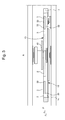
- la
figure 1 est une vue en perspective d'un balancier conforme à l'invention selon un premier mode de réalisation ; - la
figure 2 est une vue en perspective d'un balancier conforme à l'invention selon un deuxième mode de réalisation ; - les
figures 3 et4 sont respectivement des vues en coupe d'un balancier selon les premier et deuxième modes de réalisation illustrés auxfigures 1 et 2 . - Un mouvement d'horlogerie selon un exemple de réalisation va maintenant être décrit dans ce qui suit faisant référence conjointement aux
figures 1, 2 ,3 et4 . - L'invention concerne ainsi un balancier 1 à réglage d'inertie, pour pièce d'horlogerie, comprenant un moyeu 4 définissant l'axe de pivotement A du balancier 1, une serge 10, un voile 11 s'étendant entre un plan inférieur Pi et un plan supérieur Ps de part et d'autre d'un plan médian Pm, le voile 11 comprenant au moins un bras 2 reliant la serge 10 au moyeu 4, l'au moins un bras 2 comprenant un logement 3 configuré pour recevoir et maintenir en place au moins une masselotte 5.
- Selon l'invention, le balancier présente une face avant 12 présentant une noyure 14 et une face arrière 13 pouvant aussi être noyurée.
- Selon un mode de réalisation particulier, la hauteur de la serge 10 peut être identique au voile 11, dans ce cas le balancier 1 ne présente aucune noyure ce qui permet d'obtenir un balancier le plus compact possible.
- Tel qu'illustré, le balancier 1 comprend quatre bras, formant un moyeu 4 à leur intersection, le moyeu 4 étant muni d'un orifice 40 destiné à recevoir un axe de balancier 41, le voile 11 étant ainsi formé par les quatre bras et le moyeu 4.
- La serge 10 est de forme circulaire et ne présente aucune partie saillante, tout comme les bras 2, de sorte que le balancier 1 soit le plus compact possible.
- Comme on peut l'observer sur les figures, la masselotte 5 est de forme cylindrique et comprend une face avant 52 et une face arrière 53 et peut présenter selon un mode de réalisation de l'invention des ailes supérieure 54 et inférieure 55.
- De manière avantageuse, chaque masselotte 5 est pincée dans un logement 3 dans une position de service où un plan médian qu'elle comporte est confondu avec le plan médian Pm du voile 11.
- Le balancier 1 comporte des parties rigides constituées par le moyeu 4, la serge 10, et les bras 2 reliant la serge 10 au moyeu 4. Le logement 3 est délimité, d'une part par une partie rigide du balancier 1, et d'autre part un bras 20 déformable élastiquement.
- Selon un mode de réalisation particulier de l'invention, non illustré sur les figures, la serge 10 du balancier est de même épaisseur que les bras 2 du balancier 1 et est ainsi confondue avec les bras 2 du balancier, les bras 2 et la serge 10 formant alors un élément plan.
- Selon l'invention le logement 3 est délimité par une partie rigide du bras 2, et par une partie élastique 20 solidaire d'une partie rigide du bras 2, la partie élastique 20 étant en permanence rappelé vers la partie rigide du bras 2 délimitant le logement 3.
- De manière avantageuse, le bras 2 présente dans le prolongement du logement 3 un évidement 21 destiné à faciliter la déformation de la partie élastique 20.
- Selon un mode de réalisation préférentiel le logement 3 est sensiblement de la même forme que la masselotte 5. Ce mode de réalisation est particulièrement avantageux car il permet de limiter l'épaisseur du balancier 1 une fois les masselottes 5 montées sur le balancier 1.
- Dans ce mode de réalisation préférentiel, la partie élastique 20 s'étend dans le plan médian Pm du voile, le bras 2 présentant un évidement 21 facilitant la déformation de la partie élastique 20.
- Le balancier 1 comprend également des masselottes 5 de réglage sous la forme de cylindre, les masselottes 5 étant munies d'une ouverture 50 en forme de demi-lune, ou toutes autres formes, et des moyens d'entraînement 51 tels qu'une encoche de réglage ou tout autre moyens connu de l'homme du métier pour régler la position de la masselotte 5.
- Selon un premier mode de réalisation, illustré aux
figures 1 et3 , le logement 3 et la partie élastique 20 de forme complémentaire à la masselotte 5 comprennent des arrêts 30 à proximité des bords supérieur et inférieur du logement 3 respectivement au niveau du plan supérieur Ps et du plan inférieur Pi pour maintenir en place la masselotte 5 selon le plan médian Pm dans le logement 3 tout en la laissant libre en rotation. - De tels logements 3 permettent d'avoir des masselottes 5 entièrement noyées dans les bras 2 du balancier 1. Lors de la mise en place des masselottes 5 dans les logements 3, les masselottes sont pincées dans les logements 3 et sont ainsi maintenues par friction dans leur position sous l'effet de l'élasticité du bras élastique 20.
- Selon un deuxième mode de réalisation, visible aux
figures 2 et4 , la masselotte 5 comprend des ailes supérieures et inférieures destinées à prendre appui de part et d'autre du bras 2, et plus précisément de part et d'autre du logement 3, respectivement au niveau du plan inférieur Pi et du plan supérieur Ps de manière à maintenir la masselotte 5 dans le logement 3 tout en la laissant libre en rotation dans le dit logement 3. - De manière avantageuse, la masselotte 5 est intégrée dans le bras 2 du balancier 1 de manière que les faces avant et face arrière sont sensiblement dans le plan supérieur Ps et le plan inférieur Pi. Par sensiblement, on entend que les faces avant 52 et arrière 53 sont en retrait de 0µm à 1 mm par rapport au plan supérieur Ps et au plan inférieur Pi dans le premier mode de réalisation et que les ailes supérieures et inférieures de la masselotte 5 sont saillantes de 0µm à 0.6mm par rapport au plan supérieur Ps et au plan inférieur Pi dans le deuxième mode de réalisation. Un tel agencement permet d'obtenir un balancier à réglage d'inertie présentant un encombrement réduit.
- Un tel balancier 1 conforme à l'invention permet notamment de monter les masselottes 5 sur les bras 2 du balancier 1 quel que soit le sens de montage de ce dernier. De manière générale, l'homme du métier choisira le sens de montage des masselottes 5 sur le balancier 1 en fonction de la facilité d'accès aux masselottes 5 une fois le balancier 1 monté dans un mouvement.
- L'invention concerne également un mouvement horloger et une pièce d'horlogerie équipés d'un balancier conforme à l'invention.
- Grâce à ces différents aspects de l'invention, on dispose d'un balancier compact permettant de réduire l'épaisseur du mouvement horloger et peu couteux à fabriquer.
- Bien entendu, la présente invention ne se limite pas à l'exemple illustré et est susceptible de diverses variantes et modifications qui apparaîtront à l'homme de l'art.
-
- 1. Balancier,
- 10. Serge,
- 11. Voile,
- 12. Face avant du balancier,
- 13. Face arrière du balancier,
- 14. Noyure,
- 2. Bras,
- 20. Partie élastique,
- 21. Evidement,
- 3. Logements,
- 30. Arrêts,
- 4. Moyeu,
- 40. Orifice,
- 41. Axe du balancier 5. Masselotte,
- 50. Ouverture,
- 51. Moyens d'entrainement,
- 52. Face avant de la masselotte,
- 53. Face arrière de la masselotte,
- 54. Aile supérieure de la masselotte,
- 55. Aile inférieure de la masselotte,
- A. Axe de pivotement ;
- Pm. Plan médian ;
- Pi. Plan inférieur ;
- Ps. Plan supérieur.
Claims (14)
- Balancier (1) à réglage d'inertie, pour pièce d'horlogerie, comprenant un moyeu (4) définissant l'axe de pivotement (A) dudit balancier (1), une serge (10), un voile (11) s'étendant entre un plan inférieur (Pi) et un plan supérieur (Ps) de part et d'autre d'un plan médian (Pm), ledit voile (11) comprenant au moins un bras (2) reliant ladite serge (10) audit moyeu (4), ledit au moins un bras (2) comprenant un logement (3) configuré pour recevoir et maintenir en place au moins une masselotte (5),
caractérisé en ce que ladite au moins une masselotte (5) présente une face avant (52) et une face arrière (53) et est intégrée dans ledit bras (2) dudit balancier (1), de manière que lesdites faces avant et face arrière sont sensiblement dans ledit plan supérieur (Ps) et ledit plan inférieur (Pi). - Balancier (1) selon la revendication 1, dans lequel ladite face avant (52) et ladite face arrière (53) de ladite au moins une masselotte (5) sont en retrait de 0µm à 1 mm par rapport audit plan supérieur (Ps) et audit plan inférieur (Pi).
- Balancier (1) selon la revendication 1, dans lequel ladite face avant (52) et ladite face arrière (53) de ladite au moins une masselotte (5) sont saillantes de 0µm à 0.6mm par rapport audit plan supérieur (Ps) et au plan inférieur (Pi).
- Balancier (1) selon l'une quelconque des revendications 1 à 3, dans lequel ladite au moins une masselotte (5) est dans ledit plan médian (Pm) dudit voile.
- Balancier (1) selon l'une quelconque des revendications 1 à 4, dans lequel ledit logement (3) et ladite au moins une masselotte (5) sont de forme complémentaire.
- Balancier (1) selon l'une quelconque des revendications 1 à 5, dans lequel ladite au moins une masselotte (5) est pincée avec un couple de retenue prédéterminé au sein dudit logement (3).
- Balancier (1) selon l'une quelconque des revendications 1 à 6, dans lequel dans lequel ladite au moins une masselotte (5) est cylindrique.
- Balancier (1) selon l'une quelconque des revendications 1 à 7, dans lequel ledit bras (2) présente une partie élastique (20) s'étendant dans ledit plan médian (Pm), ladite partie élastique (20) étant apte à se déformer lors du montage de ladite au moins une masselotte (5).
- Balancier (1) selon l'une quelconque des revendications 1 à 8, dans lequel ledit logement (3) comprend des arrêts (30) au niveau du plan supérieur (Ps) et du plan inférieur (Pi) pour maintenir axialement en place ladite au moins une masselotte (5).
- Balancier (1) selon l'une quelconque des revendications 1 à 9, dans lequel ladite au moins une masselotte (5) comprend des ailes supérieures (54) et des ailes inférieures (55) destinées à prendre appui de part et d'autre dudit bras (2) respectivement au niveau du plan inférieur (Pi) et du plan supérieur (Ps) pour maintenir axialement en place ladite au moins une masselotte (5).
- Balancier (1) selon l'une quelconque des revendications 1 à 9, dans lequel ladite au moins une masselotte (5) est chassée dans ledit logement (3) dudit bras (2) dudit balancier (1).
- Balancier (1) selon l'une quelconque des revendications 1 à 11, dans lequel ledit bras (2) et ladite serge (10) ont la même épaisseur.
- Mouvement d'horlogerie comprenant un balancier (1) selon l'une des revendications 1 à 12.
- Pièce d'horlogerie comprenant un mouvement selon la revendication 11.
Priority Applications (6)
| Application Number | Priority Date | Filing Date | Title |
|---|---|---|---|
| EP14182343.5A EP2990882B1 (fr) | 2014-08-26 | 2014-08-26 | Balancier à réglage d'inertie |
| US14/828,709 US9547278B2 (en) | 2014-08-26 | 2015-08-18 | Balance with inertia adjustment |
| JP2015163495A JP6086961B2 (ja) | 2014-08-26 | 2015-08-21 | 慣性調整機能付きバランス |
| RU2015136080A RU2693519C2 (ru) | 2014-08-26 | 2015-08-25 | Баланс с регулировкой инерции для часовых изделий, часовой механизм и часовое изделие |
| CN201510526600.6A CN105388743B (zh) | 2014-08-26 | 2015-08-25 | 具有惯性调整装置的摆轮 |
| HK16110592.3A HK1222460B (en) | 2014-08-26 | 2016-09-06 | Balance with inertia adjustment |
Applications Claiming Priority (1)
| Application Number | Priority Date | Filing Date | Title |
|---|---|---|---|
| EP14182343.5A EP2990882B1 (fr) | 2014-08-26 | 2014-08-26 | Balancier à réglage d'inertie |
Publications (2)
| Publication Number | Publication Date |
|---|---|
| EP2990882A1 true EP2990882A1 (fr) | 2016-03-02 |
| EP2990882B1 EP2990882B1 (fr) | 2020-01-15 |
Family
ID=51392196
Family Applications (1)
| Application Number | Title | Priority Date | Filing Date |
|---|---|---|---|
| EP14182343.5A Active EP2990882B1 (fr) | 2014-08-26 | 2014-08-26 | Balancier à réglage d'inertie |
Country Status (5)
| Country | Link |
|---|---|
| US (1) | US9547278B2 (fr) |
| EP (1) | EP2990882B1 (fr) |
| JP (1) | JP6086961B2 (fr) |
| CN (1) | CN105388743B (fr) |
| RU (1) | RU2693519C2 (fr) |
Families Citing this family (8)
| Publication number | Priority date | Publication date | Assignee | Title |
|---|---|---|---|---|
| EP2990883A1 (fr) * | 2014-08-29 | 2016-03-02 | Nivarox-FAR S.A. | Ensemble balancier-spiral d'horlogerie |
| EP3252546B1 (fr) * | 2016-06-03 | 2019-08-28 | The Swatch Group Research and Development Ltd | Mécanisme d'horlogerie à réglage d'inertie de balancier |
| EP3502786A1 (fr) | 2017-12-22 | 2019-06-26 | The Swatch Group Research and Development Ltd | Balancier pour pièce d'horlogerie et procédé de fabrication d'un tel balancier |
| EP3525046B1 (fr) * | 2018-02-12 | 2024-07-10 | The Swatch Group Research and Development Ltd | Oscillateur d'horlogerie insensible aux accelerations angulaires du porte |
| USD922893S1 (en) * | 2019-05-07 | 2021-06-22 | Nivarox-Far Sa | Watch component |
| EP3736640B1 (fr) | 2019-05-07 | 2022-12-21 | Nivarox-FAR S.A. | Balancier d'horlogerie |
| EP3835879B1 (fr) * | 2019-12-09 | 2024-01-24 | The Swatch Group Research and Development Ltd | Mecanisme resonateur d'horlogerie avec masse inertielle a reglage d'inertie et de balourd |
| EP3839656B1 (fr) * | 2019-12-18 | 2023-12-13 | Nivarox-FAR S.A. | Balancier d'horlogerie |
Citations (6)
| Publication number | Priority date | Publication date | Assignee | Title |
|---|---|---|---|---|
| US510202A (en) * | 1893-01-19 | 1893-12-05 | smith | |
| EP1351103A1 (fr) | 2002-03-21 | 2003-10-08 | Chopard Manufacture SA | Balancier muni d'un dispositif de réglage |
| CH698024B1 (fr) * | 2005-03-23 | 2009-04-30 | Patek Philippe Sa | Balancier inertiel. |
| EP2410386A1 (fr) * | 2010-07-19 | 2012-01-25 | Nivarox-FAR S.A. | Balancier à réglage d'inertie avec insert |
| CH703463A2 (fr) * | 2010-07-19 | 2012-01-31 | Nivarox Sa | Balancier à réglage d'inertie sans insert. |
| CH705238A2 (fr) | 2011-07-15 | 2013-01-15 | Nivarox Sa | Balancier à réglage d'inertie pour mouvement d'horlogerie. |
Family Cites Families (11)
| Publication number | Priority date | Publication date | Assignee | Title |
|---|---|---|---|---|
| US455787A (en) * | 1890-05-24 | 1891-07-14 | Balance-wheel for time-pieces | |
| US631103A (en) * | 1899-03-03 | 1899-08-15 | Antoine Borel | Compensation watch-balance. |
| US1350035A (en) * | 1920-03-02 | 1920-08-17 | Povelsen Ingild | Compensating balance-wheel |
| US2770942A (en) * | 1953-03-03 | 1956-11-20 | Elgin Nat Watch Co | Horological balance with adjustable moment of inertia |
| US2880570A (en) * | 1956-11-26 | 1959-04-07 | Elgin Nat Watch Co | Balance with adjustable moment of inertia |
| US3382667A (en) * | 1966-04-01 | 1968-05-14 | Hamilton Watch Co | Watch regulator |
| US3455104A (en) * | 1968-01-25 | 1969-07-15 | Hamilton Watch Co | Watch rate regulation |
| EP2677369B1 (fr) * | 2010-06-11 | 2015-01-14 | Montres Breguet SA | Balancier haute fréquence pour pièce d'horlogerie |
| EP2410387B1 (fr) * | 2010-07-19 | 2016-07-06 | Nivarox-FAR S.A. | Balancier à réglage d'inertie sans insert |
| USD700535S1 (en) * | 2011-12-28 | 2014-03-04 | Nivarox-Far S.A. | Balance wheel with control knobs |
| JP6070937B2 (ja) * | 2013-02-20 | 2017-02-01 | セイコーインスツル株式会社 | てんぷ、時計用ムーブメント及び機械式時計 |
-
2014
- 2014-08-26 EP EP14182343.5A patent/EP2990882B1/fr active Active
-
2015
- 2015-08-18 US US14/828,709 patent/US9547278B2/en active Active
- 2015-08-21 JP JP2015163495A patent/JP6086961B2/ja active Active
- 2015-08-25 RU RU2015136080A patent/RU2693519C2/ru active
- 2015-08-25 CN CN201510526600.6A patent/CN105388743B/zh active Active
Patent Citations (6)
| Publication number | Priority date | Publication date | Assignee | Title |
|---|---|---|---|---|
| US510202A (en) * | 1893-01-19 | 1893-12-05 | smith | |
| EP1351103A1 (fr) | 2002-03-21 | 2003-10-08 | Chopard Manufacture SA | Balancier muni d'un dispositif de réglage |
| CH698024B1 (fr) * | 2005-03-23 | 2009-04-30 | Patek Philippe Sa | Balancier inertiel. |
| EP2410386A1 (fr) * | 2010-07-19 | 2012-01-25 | Nivarox-FAR S.A. | Balancier à réglage d'inertie avec insert |
| CH703463A2 (fr) * | 2010-07-19 | 2012-01-31 | Nivarox Sa | Balancier à réglage d'inertie sans insert. |
| CH705238A2 (fr) | 2011-07-15 | 2013-01-15 | Nivarox Sa | Balancier à réglage d'inertie pour mouvement d'horlogerie. |
Also Published As
| Publication number | Publication date |
|---|---|
| EP2990882B1 (fr) | 2020-01-15 |
| RU2693519C2 (ru) | 2019-07-03 |
| US9547278B2 (en) | 2017-01-17 |
| US20160062314A1 (en) | 2016-03-03 |
| CN105388743A (zh) | 2016-03-09 |
| JP6086961B2 (ja) | 2017-03-01 |
| RU2015136080A (ru) | 2017-03-03 |
| RU2015136080A3 (fr) | 2019-03-05 |
| CN105388743B (zh) | 2017-12-05 |
| JP2016045209A (ja) | 2016-04-04 |
| HK1222460A1 (zh) | 2017-06-30 |
Similar Documents
| Publication | Publication Date | Title |
|---|---|---|
| EP2990882B1 (fr) | Balancier à réglage d'inertie | |
| EP3158402B1 (fr) | Mobile d'horlogerie | |
| EP2009244B1 (fr) | Dispositif de retenue axiale d'aubes montées sur un disque de rotor de turbomachine | |
| EP2253535B1 (fr) | Dispositif à masses réparties pour réduire les vibrations engendrées par un rotor de sustentation d'un giravion, et moyeu d'un rotor muni d'un tel dispositif | |
| EP1738229B1 (fr) | Couronne pour pièce d'horlogerie avec dispositif de débrayage | |
| EP2230572B1 (fr) | Système de serrage radial pour un composant horloger | |
| EP3227754B1 (fr) | Ensemble balancier-spiral d'horlogerie | |
| CH709920A2 (fr) | Ensemble à mobile de freinage d'horlogerie. | |
| CH705238A2 (fr) | Balancier à réglage d'inertie pour mouvement d'horlogerie. | |
| EP3558798B1 (fr) | Système aérodynamique rétractable pour véhicule automobile | |
| EP2474871B1 (fr) | Clé de raquette pour balancier spiral | |
| EP2230571B1 (fr) | Système de serrage radial pour un composant horloger | |
| FR3043801A3 (fr) | Balancier a reglage d'inertie | |
| WO2016016456A2 (fr) | Dispositif d'assemblage et de reglage d'un spiral | |
| CH710017A2 (fr) | Balancier à réglage d'inertie. | |
| CH711766B1 (fr) | Balancier à réglage d'inertie. | |
| EP3736640A1 (fr) | Balancier d'horlogerie | |
| EP3183618B1 (fr) | Aiguille de montre | |
| EP1331402B1 (fr) | Dispositif de commande d'aube variable | |
| EP2506093B1 (fr) | Balancier pour mouvement d'horlogerie | |
| FR2971980A1 (fr) | Vehicule comportant un absorbeur de choc et absorbeur de choc correspondant | |
| EP4290314B1 (fr) | Roue pour un système d'échappement a inertie réduite | |
| EP3499318A1 (fr) | Système oscillant pour montre | |
| CH716970A2 (fr) | Balancier d'horlogerie. | |
| EP3839655A1 (fr) | Balancier d'horlogerie |
Legal Events
| Date | Code | Title | Description |
|---|---|---|---|
| PUAI | Public reference made under article 153(3) epc to a published international application that has entered the european phase |
Free format text: ORIGINAL CODE: 0009012 |
|
| AK | Designated contracting states |
Kind code of ref document: A1 Designated state(s): AL AT BE BG CH CY CZ DE DK EE ES FI FR GB GR HR HU IE IS IT LI LT LU LV MC MK MT NL NO PL PT RO RS SE SI SK SM TR |
|
| AX | Request for extension of the european patent |
Extension state: BA ME |
|
| 17P | Request for examination filed |
Effective date: 20160902 |
|
| RBV | Designated contracting states (corrected) |
Designated state(s): AL AT BE BG CH CY CZ DE DK EE ES FI FR GB GR HR HU IE IS IT LI LT LU LV MC MK MT NL NO PL PT RO RS SE SI SK SM TR |
|
| STAA | Information on the status of an ep patent application or granted ep patent |
Free format text: STATUS: EXAMINATION IS IN PROGRESS |
|
| 17Q | First examination report despatched |
Effective date: 20190225 |
|
| GRAP | Despatch of communication of intention to grant a patent |
Free format text: ORIGINAL CODE: EPIDOSNIGR1 |
|
| STAA | Information on the status of an ep patent application or granted ep patent |
Free format text: STATUS: GRANT OF PATENT IS INTENDED |
|
| INTG | Intention to grant announced |
Effective date: 20190930 |
|
| GRAS | Grant fee paid |
Free format text: ORIGINAL CODE: EPIDOSNIGR3 |
|
| GRAA | (expected) grant |
Free format text: ORIGINAL CODE: 0009210 |
|
| STAA | Information on the status of an ep patent application or granted ep patent |
Free format text: STATUS: THE PATENT HAS BEEN GRANTED |
|
| AK | Designated contracting states |
Kind code of ref document: B1 Designated state(s): AL AT BE BG CH CY CZ DE DK EE ES FI FR GB GR HR HU IE IS IT LI LT LU LV MC MK MT NL NO PL PT RO RS SE SI SK SM TR |
|
| REG | Reference to a national code |
Ref country code: CH Ref legal event code: EP Ref country code: GB Ref legal event code: FG4D Free format text: NOT ENGLISH |
|
| REG | Reference to a national code |
Ref country code: CH Ref legal event code: NV Representative=s name: ICB INGENIEURS CONSEILS EN BREVETS SA, CH |
|
| REG | Reference to a national code |
Ref country code: IE Ref legal event code: FG4D Free format text: LANGUAGE OF EP DOCUMENT: FRENCH |
|
| REG | Reference to a national code |
Ref country code: DE Ref legal event code: R096 Ref document number: 602014059986 Country of ref document: DE |
|
| REG | Reference to a national code |
Ref country code: AT Ref legal event code: REF Ref document number: 1225693 Country of ref document: AT Kind code of ref document: T Effective date: 20200215 |
|
| REG | Reference to a national code |
Ref country code: NL Ref legal event code: MP Effective date: 20200115 |
|
| REG | Reference to a national code |
Ref country code: LT Ref legal event code: MG4D |
|
| PG25 | Lapsed in a contracting state [announced via postgrant information from national office to epo] |
Ref country code: NL Free format text: LAPSE BECAUSE OF FAILURE TO SUBMIT A TRANSLATION OF THE DESCRIPTION OR TO PAY THE FEE WITHIN THE PRESCRIBED TIME-LIMIT Effective date: 20200115 Ref country code: PT Free format text: LAPSE BECAUSE OF FAILURE TO SUBMIT A TRANSLATION OF THE DESCRIPTION OR TO PAY THE FEE WITHIN THE PRESCRIBED TIME-LIMIT Effective date: 20200607 Ref country code: FI Free format text: LAPSE BECAUSE OF FAILURE TO SUBMIT A TRANSLATION OF THE DESCRIPTION OR TO PAY THE FEE WITHIN THE PRESCRIBED TIME-LIMIT Effective date: 20200115 Ref country code: RS Free format text: LAPSE BECAUSE OF FAILURE TO SUBMIT A TRANSLATION OF THE DESCRIPTION OR TO PAY THE FEE WITHIN THE PRESCRIBED TIME-LIMIT Effective date: 20200115 Ref country code: NO Free format text: LAPSE BECAUSE OF FAILURE TO SUBMIT A TRANSLATION OF THE DESCRIPTION OR TO PAY THE FEE WITHIN THE PRESCRIBED TIME-LIMIT Effective date: 20200415 |
|
| PG25 | Lapsed in a contracting state [announced via postgrant information from national office to epo] |
Ref country code: BG Free format text: LAPSE BECAUSE OF FAILURE TO SUBMIT A TRANSLATION OF THE DESCRIPTION OR TO PAY THE FEE WITHIN THE PRESCRIBED TIME-LIMIT Effective date: 20200415 Ref country code: HR Free format text: LAPSE BECAUSE OF FAILURE TO SUBMIT A TRANSLATION OF THE DESCRIPTION OR TO PAY THE FEE WITHIN THE PRESCRIBED TIME-LIMIT Effective date: 20200115 Ref country code: LV Free format text: LAPSE BECAUSE OF FAILURE TO SUBMIT A TRANSLATION OF THE DESCRIPTION OR TO PAY THE FEE WITHIN THE PRESCRIBED TIME-LIMIT Effective date: 20200115 Ref country code: SE Free format text: LAPSE BECAUSE OF FAILURE TO SUBMIT A TRANSLATION OF THE DESCRIPTION OR TO PAY THE FEE WITHIN THE PRESCRIBED TIME-LIMIT Effective date: 20200115 Ref country code: IS Free format text: LAPSE BECAUSE OF FAILURE TO SUBMIT A TRANSLATION OF THE DESCRIPTION OR TO PAY THE FEE WITHIN THE PRESCRIBED TIME-LIMIT Effective date: 20200515 Ref country code: GR Free format text: LAPSE BECAUSE OF FAILURE TO SUBMIT A TRANSLATION OF THE DESCRIPTION OR TO PAY THE FEE WITHIN THE PRESCRIBED TIME-LIMIT Effective date: 20200416 |
|
| REG | Reference to a national code |
Ref country code: DE Ref legal event code: R097 Ref document number: 602014059986 Country of ref document: DE |
|
| PG25 | Lapsed in a contracting state [announced via postgrant information from national office to epo] |
Ref country code: EE Free format text: LAPSE BECAUSE OF FAILURE TO SUBMIT A TRANSLATION OF THE DESCRIPTION OR TO PAY THE FEE WITHIN THE PRESCRIBED TIME-LIMIT Effective date: 20200115 Ref country code: SM Free format text: LAPSE BECAUSE OF FAILURE TO SUBMIT A TRANSLATION OF THE DESCRIPTION OR TO PAY THE FEE WITHIN THE PRESCRIBED TIME-LIMIT Effective date: 20200115 Ref country code: DK Free format text: LAPSE BECAUSE OF FAILURE TO SUBMIT A TRANSLATION OF THE DESCRIPTION OR TO PAY THE FEE WITHIN THE PRESCRIBED TIME-LIMIT Effective date: 20200115 Ref country code: CZ Free format text: LAPSE BECAUSE OF FAILURE TO SUBMIT A TRANSLATION OF THE DESCRIPTION OR TO PAY THE FEE WITHIN THE PRESCRIBED TIME-LIMIT Effective date: 20200115 Ref country code: RO Free format text: LAPSE BECAUSE OF FAILURE TO SUBMIT A TRANSLATION OF THE DESCRIPTION OR TO PAY THE FEE WITHIN THE PRESCRIBED TIME-LIMIT Effective date: 20200115 Ref country code: SK Free format text: LAPSE BECAUSE OF FAILURE TO SUBMIT A TRANSLATION OF THE DESCRIPTION OR TO PAY THE FEE WITHIN THE PRESCRIBED TIME-LIMIT Effective date: 20200115 Ref country code: ES Free format text: LAPSE BECAUSE OF FAILURE TO SUBMIT A TRANSLATION OF THE DESCRIPTION OR TO PAY THE FEE WITHIN THE PRESCRIBED TIME-LIMIT Effective date: 20200115 Ref country code: LT Free format text: LAPSE BECAUSE OF FAILURE TO SUBMIT A TRANSLATION OF THE DESCRIPTION OR TO PAY THE FEE WITHIN THE PRESCRIBED TIME-LIMIT Effective date: 20200115 |
|
| REG | Reference to a national code |
Ref country code: AT Ref legal event code: MK05 Ref document number: 1225693 Country of ref document: AT Kind code of ref document: T Effective date: 20200115 |
|
| PLBE | No opposition filed within time limit |
Free format text: ORIGINAL CODE: 0009261 |
|
| STAA | Information on the status of an ep patent application or granted ep patent |
Free format text: STATUS: NO OPPOSITION FILED WITHIN TIME LIMIT |
|
| 26N | No opposition filed |
Effective date: 20201016 |
|
| PG25 | Lapsed in a contracting state [announced via postgrant information from national office to epo] |
Ref country code: IT Free format text: LAPSE BECAUSE OF FAILURE TO SUBMIT A TRANSLATION OF THE DESCRIPTION OR TO PAY THE FEE WITHIN THE PRESCRIBED TIME-LIMIT Effective date: 20200115 Ref country code: AT Free format text: LAPSE BECAUSE OF FAILURE TO SUBMIT A TRANSLATION OF THE DESCRIPTION OR TO PAY THE FEE WITHIN THE PRESCRIBED TIME-LIMIT Effective date: 20200115 |
|
| PG25 | Lapsed in a contracting state [announced via postgrant information from national office to epo] |
Ref country code: SI Free format text: LAPSE BECAUSE OF FAILURE TO SUBMIT A TRANSLATION OF THE DESCRIPTION OR TO PAY THE FEE WITHIN THE PRESCRIBED TIME-LIMIT Effective date: 20200115 Ref country code: PL Free format text: LAPSE BECAUSE OF FAILURE TO SUBMIT A TRANSLATION OF THE DESCRIPTION OR TO PAY THE FEE WITHIN THE PRESCRIBED TIME-LIMIT Effective date: 20200115 |
|
| PG25 | Lapsed in a contracting state [announced via postgrant information from national office to epo] |
Ref country code: MC Free format text: LAPSE BECAUSE OF FAILURE TO SUBMIT A TRANSLATION OF THE DESCRIPTION OR TO PAY THE FEE WITHIN THE PRESCRIBED TIME-LIMIT Effective date: 20200115 |
|
| PG25 | Lapsed in a contracting state [announced via postgrant information from national office to epo] |
Ref country code: LU Free format text: LAPSE BECAUSE OF NON-PAYMENT OF DUE FEES Effective date: 20200826 |
|
| REG | Reference to a national code |
Ref country code: BE Ref legal event code: MM Effective date: 20200831 |
|
| PG25 | Lapsed in a contracting state [announced via postgrant information from national office to epo] |
Ref country code: IE Free format text: LAPSE BECAUSE OF NON-PAYMENT OF DUE FEES Effective date: 20200826 Ref country code: BE Free format text: LAPSE BECAUSE OF NON-PAYMENT OF DUE FEES Effective date: 20200831 |
|
| PG25 | Lapsed in a contracting state [announced via postgrant information from national office to epo] |
Ref country code: TR Free format text: LAPSE BECAUSE OF FAILURE TO SUBMIT A TRANSLATION OF THE DESCRIPTION OR TO PAY THE FEE WITHIN THE PRESCRIBED TIME-LIMIT Effective date: 20200115 Ref country code: MT Free format text: LAPSE BECAUSE OF FAILURE TO SUBMIT A TRANSLATION OF THE DESCRIPTION OR TO PAY THE FEE WITHIN THE PRESCRIBED TIME-LIMIT Effective date: 20200115 Ref country code: CY Free format text: LAPSE BECAUSE OF FAILURE TO SUBMIT A TRANSLATION OF THE DESCRIPTION OR TO PAY THE FEE WITHIN THE PRESCRIBED TIME-LIMIT Effective date: 20200115 |
|
| PG25 | Lapsed in a contracting state [announced via postgrant information from national office to epo] |
Ref country code: MK Free format text: LAPSE BECAUSE OF FAILURE TO SUBMIT A TRANSLATION OF THE DESCRIPTION OR TO PAY THE FEE WITHIN THE PRESCRIBED TIME-LIMIT Effective date: 20200115 Ref country code: AL Free format text: LAPSE BECAUSE OF FAILURE TO SUBMIT A TRANSLATION OF THE DESCRIPTION OR TO PAY THE FEE WITHIN THE PRESCRIBED TIME-LIMIT Effective date: 20200115 |
|
| P01 | Opt-out of the competence of the unified patent court (upc) registered |
Effective date: 20230611 |
|
| PGFP | Annual fee paid to national office [announced via postgrant information from national office to epo] |
Ref country code: DE Payment date: 20250724 Year of fee payment: 12 |
|
| PGFP | Annual fee paid to national office [announced via postgrant information from national office to epo] |
Ref country code: GB Payment date: 20250724 Year of fee payment: 12 |
|
| PGFP | Annual fee paid to national office [announced via postgrant information from national office to epo] |
Ref country code: FR Payment date: 20250723 Year of fee payment: 12 |
|
| PGFP | Annual fee paid to national office [announced via postgrant information from national office to epo] |
Ref country code: CH Payment date: 20250901 Year of fee payment: 12 |