EP2990850A1 - Dispositif d'acquisition d'image et procédé et système d'acquisition d'informations de mise au point pour un échantillon - Google Patents
Dispositif d'acquisition d'image et procédé et système d'acquisition d'informations de mise au point pour un échantillon Download PDFInfo
- Publication number
- EP2990850A1 EP2990850A1 EP14788270.8A EP14788270A EP2990850A1 EP 2990850 A1 EP2990850 A1 EP 2990850A1 EP 14788270 A EP14788270 A EP 14788270A EP 2990850 A1 EP2990850 A1 EP 2990850A1
- Authority
- EP
- European Patent Office
- Prior art keywords
- sample
- objective lens
- pickup element
- image pickup
- image
- Prior art date
- Legal status (The legal status is an assumption and is not a legal conclusion. Google has not performed a legal analysis and makes no representation as to the accuracy of the status listed.)
- Granted
Links
Images


Classifications
-
- G—PHYSICS
- G02—OPTICS
- G02B—OPTICAL ELEMENTS, SYSTEMS OR APPARATUS
- G02B21/00—Microscopes
- G02B21/36—Microscopes arranged for photographic purposes or projection purposes or digital imaging or video purposes including associated control and data processing arrangements
- G02B21/365—Control or image processing arrangements for digital or video microscopes
-
- G—PHYSICS
- G02—OPTICS
- G02B—OPTICAL ELEMENTS, SYSTEMS OR APPARATUS
- G02B21/00—Microscopes
- G02B21/02—Objectives
-
- G—PHYSICS
- G02—OPTICS
- G02B—OPTICAL ELEMENTS, SYSTEMS OR APPARATUS
- G02B21/00—Microscopes
- G02B21/24—Base structure
- G02B21/241—Devices for focusing
- G02B21/244—Devices for focusing using image analysis techniques
-
- G—PHYSICS
- G02—OPTICS
- G02B—OPTICAL ELEMENTS, SYSTEMS OR APPARATUS
- G02B21/00—Microscopes
- G02B21/24—Base structure
- G02B21/26—Stages; Adjusting means therefor
-
- G—PHYSICS
- G02—OPTICS
- G02B—OPTICAL ELEMENTS, SYSTEMS OR APPARATUS
- G02B21/00—Microscopes
- G02B21/36—Microscopes arranged for photographic purposes or projection purposes or digital imaging or video purposes including associated control and data processing arrangements
- G02B21/361—Optical details, e.g. image relay to the camera or image sensor
-
- G—PHYSICS
- G02—OPTICS
- G02B—OPTICAL ELEMENTS, SYSTEMS OR APPARATUS
- G02B21/00—Microscopes
- G02B21/36—Microscopes arranged for photographic purposes or projection purposes or digital imaging or video purposes including associated control and data processing arrangements
- G02B21/365—Control or image processing arrangements for digital or video microscopes
- G02B21/367—Control or image processing arrangements for digital or video microscopes providing an output produced by processing a plurality of individual source images, e.g. image tiling, montage, composite images, depth sectioning, image comparison
-
- G—PHYSICS
- G02—OPTICS
- G02B—OPTICAL ELEMENTS, SYSTEMS OR APPARATUS
- G02B7/00—Mountings, adjusting means, or light-tight connections, for optical elements
- G02B7/28—Systems for automatic generation of focusing signals
- G02B7/36—Systems for automatic generation of focusing signals using image sharpness techniques, e.g. image processing techniques for generating autofocus signals
-
- H—ELECTRICITY
- H04—ELECTRIC COMMUNICATION TECHNIQUE
- H04N—PICTORIAL COMMUNICATION, e.g. TELEVISION
- H04N23/00—Cameras or camera modules comprising electronic image sensors; Control thereof
- H04N23/60—Control of cameras or camera modules
- H04N23/67—Focus control based on electronic image sensor signals
- H04N23/673—Focus control based on electronic image sensor signals based on contrast or high frequency components of image signals, e.g. hill climbing method
Definitions
- the present invention relates to an image acquisition device and a method and system for acquiring focus information of a sample.
- image acquisition devices for observing a sample such as a tissue cell
- irregularities on a surface of the sample may have an out-of-focus region in an image. Therefore, image acquisition devices employing various focusing methods such as a dynamic focus scheme which captures an image of the sample while acquiring focus information and a prefocus scheme which acquires focus information before capturing the image of the sample have been developed.
- Patent Literature 1 Japanese Patent Application Laid-Open No. 2012-108184
- the above-mentioned conventional device can grasp in-focus regions which are in focus and out-of-focus regions which are out of focus in images captured by an image pickup element. This makes it possible to determine focal position information from the position of the stage at the time when a pixel column corresponding to an in-focus region captures an image.
- the position (two-dimensional position) of the sample to be subjected to imaging varies among the pixel columns, whereby focus position information of parts slightly different from each other is acquired in practice.
- the above-mentioned device is a microscope device which performs imaging at a high magnification of 20x to 40x, for example, and thus has such a small depth of field that the field of the microscope optical system is very small as compared with the sample. Therefore, for acquiring focal position information of the sample as a whole, it is necessary to perform imaging while moving the field of the microscope optical system, which seems to complicate operations in the device that does not drive the stage.
- an object of the present invention to provide an image acquisition device and a method and system for acquiring focus information of a sample, which can acquire focus information of samples rapidly and accurately.
- the image acquisition device in accordance with one aspect of the present invention comprises a stage for mounting a sample; a light source for emitting light to the sample; a lightguide optical system including an objective lens arranged so as to oppose the sample on the stage; an image pickup element for capturing an optical image of the sample guided by the lightguide optical system; a focus calculation unit for calculating focus information of the sample according to image data from the image pickup element; a first drive unit for moving a field position of the objective lens with respect to the sample; a second drive unit for changing a focal position of the objective lens with respect to the sample; and a controller for controlling the image pickup element, first drive unit, and second drive unit; the image pickup element is a two-dimensional image pickup element, adapted to perform rolling readout, having a plurality of pixel columns; the controller synchronizes movement of a predetermined part of the sample within a field of the objective lens caused by the first drive unit with the rolling readout of the image pickup element such that each pixel column of
- the system for acquiring focus information of a sample in accordance with one aspect of the present invention comprises a stage for holding the sample; a lightguide optical system including an objective lens arranged so as to oppose the sample on the stage; an image pickup element, constituted by a two-dimensional image pickup element, adapted to perform rolling readout, having a plurality of pixel columns, for capturing an optical image of the sample guided by the lightguide optical system; and a focus calculation unit for calculating focus information of the sample according to image data from the image pickup element; the system synchronizes movement of a predetermined part of the sample within a field of the objective lens with the rolling readout of the image pickup element such that each pixel column of the image pickup element is exposed to an optical image of the predetermined part in the sample, while changing a focal position of the objective lens with respect to the sample.
- the above-mentioned image acquisition device and system use as an image pickup element a two-dimensional image pickup element which is adapted to perform rolling readout while having a plurality of pixel columns.
- the rolling readout scheme which varies image data readout timings among pixel columns and thus may distort images when used for movable objects, is typically employed for objects which stand still.
- the above-mentioned image acquisition device and system synchronize the movement of a predetermined part (the same part) of the sample within the field of the objective lens with the rolling readout such that each pixel column of the image pickup element is exposed to an optical image of the predetermined part in the sample.
- image data from each pixel column includes contrast information obtained when the focal position of the objective lens is changed in the same part of the sample, whereby the focus information can be calculated rapidly and accurately according to the contrast information.
- the controller may control the first drive unit such that the predetermined part of the sample is moved at a fixed speed within the field of the objective lens. This can easily control the synchronization of the movement of the predetermined part of the sample within the field of the objective lens with the rolling readout.
- the controller may start exposing each pixel column of the image pickup element after a lapse of a predetermined time since the first drive unit starts moving the field position of the objective lens with respect to the sample. This can perform exposure favorably.
- a plurality of divisional regions where the image pickup element performs imaging may be set, while the predetermined part of the sample may be set so as to be located in a region other than end parts of the divisional regions.
- the predetermined part of the sample is more susceptible to acceleration at the time of being moved by the first drive unit. Therefore, setting the predetermined part of the sample in a region other than end parts of the divisional regions makes it possible to control the synchronization of the movement of the predetermined part of the sample within the field of the objective lens with the rolling readout more easily.
- the focus calculation unit may calculate the focus information when the first drive unit moves the field position of the objective lens between the divisional regions. This can acquire the focus information during the movement of the field position of the objective lens, whereby imaging of the sample can be executed rapidly.
- the controller may control the first drive unit such that the field position of the objective lens is moved with respect to the sample over at least three divisional regions.
- Targeting imaging lines over three or more divisional regions can shorten the time required for imaging, while simplifying control.
- the image pickup element may be adapted to switch readout directions of the rolling readout. This can extend the degree of freedom in moving directions of the predetermined part of the sample.
- Each pixel column of the image pickup element may be constituted by first and second column groups having respective readout directions different from each other. Such a configuration enables the field position of the objective lens to be bidirectionally scanned in a simple structure.
- the controller may control the second drive unit such that the focal position of the objective lens with respect to the sample reciprocates in ascending and descending directions during the synchronization of the movement of the predetermined part of the sample with the rolling readout of the image pickup element. This can acquire a greater amount of contrast information at the time when the focal position of the objective lens is changed, whereby the focus information can be calculated more accurately.
- the focus calculation unit may produce a focus map according to the calculated focus information. This can accurately produce the focus map.
- the focus calculation unit may calculate the focus information for each divisional region. This can accurately produce a focus map of the sample as a whole.
- the focusing method for an image acquisition device in accordance with one aspect of the present invention is a focusing method for an image acquisition device comprising a stage for mounting a sample; a light source for emitting light to the sample; a lightguide optical system including an objective lens arranged so as to oppose the sample on the stage; an image pickup element for capturing an optical image of the sample guided by the lightguide optical system; a focus calculation unit for calculating focus information of the sample according to image data from the image pickup element; a first drive unit for moving a field position of the objective lens with respect to the sample; a second drive unit for changing a focal position of the objective lens with respect to the sample; and a controller for controlling the image pickup element, first drive unit, and second drive unit; the method comprising using as the image pickup element a two-dimensional image pickup element, adapted to perform rolling readout, having a plurality of pixel columns; and causing the controller to synchronize movement of a predetermined part of the sample within a field of the objective lens caused by the first drive unit with the
- the method for acquiring focus information of a sample in accordance with one aspect of the present invention is a method for acquiring focus information of a sample by using a two-dimensional image pickup element, adapted to perform rolling readout, having a plurality of pixel columns; the method comprising synchronizing movement of a predetermined part of the sample within a field of an objective lens with the rolling readout of the image pickup element such that each pixel column of the image pickup element is exposed to an optical image of the predetermined part in the sample, while changing a focal position of the objective lens with respect to the sample; and acquiring the focus information of the sample according to image data from the image pickup element.
- the above-mentioned focusing method for an image acquisition device and method for acquiring focus information of a sample use as an image pickup element a two-dimensional image pickup element which is adapted to perform rolling readout while having a plurality of pixel columns.
- the rolling readout scheme which varies image data readout timings among pixel columns and thus distorts images when used for moving objects, is typically employed for objects which stand still.
- the above-mentioned focusing method for an image acquisition device and method for acquiring focus information of a sample synchronize the movement of a predetermined part (the same part) of the sample within the field of the objective lens with the rolling readout such that each pixel column is exposed to an optical image of the predetermined part in the sample.
- image data from each pixel column includes contrast information obtained when the focal position of the objective lens is changed in the same part of the sample, whereby the focus information can be calculated rapidly and accurately according to the contrast information.
- the present invention can acquire focus information of samples rapidly and accurately.
- Fig. 1 is a diagram illustrating an embodiment of the image acquisition device in accordance with the present invention.
- an image acquisition device 1 comprises a stage for mounting a sample S, a light source 3 for emitting light to the sample, a lightguide optical system 5 including an objective lens 25 arranged so as to oppose the sample S on the stage 2, and an image pickup element 6 for capturing an optical image of the sample S guided by the lightguide optical system 5.
- the image acquisition device 1 also comprises a stage drive unit (first drive unit) 11 for moving a field position of the objective lens 25 with respect to the sample S, an objective lens drive unit (second drive unit) 12 for changing the focal position of the objective lens 25 with respect to the sample S, a controller 13 for controlling the image pickup element 6, stage drive unit 11, and objective lens drive unit 12, and an image processing unit 14.
- the light source 3 is arranged on the bottom face side of the stage 2.
- any of laser diodes (LD), light-emitting diodes (LED), superluminescent diodes (SLD), and light sources of lamp type such as halogen lamps is used as the light source 3.
- the lightguide optical system 5 is constituted by an illumination optical system 21 arranged between the light source 3 and stage 2 and a microscope optical system 22 arranged between the stage 2 and image pickup element 6.
- the illumination optical system 21 has a Köhler illumination optical system constituted by a condensing lens 23 and a projection lens 24, for example, and guides the light from the light source 3 so as to irradiate the sample S with uniform light.
- the microscope optical system 22 has an objective lens 25 and an imaging lens 26 arranged on the downstream side (image pickup element 6 side) of the objective lens 25 and guides an optical image of the sample S to the image pickup element 6.
- the optical image of the sample S is an image formed by transmitted light in the case of bright field illumination, scattered light in the case of dark field illumination, and emission (fluorescence) in the case of emission measurement. It may also be an image formed by reflected light from the sample S.
- the image pickup element 6 is a two-dimensional image pickup element which is adapted to perform rolling readout while having a plurality of pixel columns.
- An example of such an image pickup element 6 is a CMOS image sensor.
- a plurality of pixel columns 31, each of which is constructed by arranging a plurality of pixels in a direction perpendicular to a readout direction, align in the readout direction on a light-receiving surface 6a of the image pickup element 6.
- a reset signal, a readout start signal, and a readout end signal are outputted according to a drive period of a drive clock, whereby exposure and readout are controlled for each pixel column 31.
- An exposure period of one pixel column 31 is a duration from discharge of electric charges triggered by the reset signal to readout of the electric charges triggered by the readout start signal.
- a readout period of one pixel column 31 is a duration from the start of readout of electric charges triggered by the readout start signal to an end of readout of electric charges triggered by the readout end signal.
- the readout start signal for the next pixel column can also be used as the readout end signal.
- readout start signals to be outputted for the respective pixel columns 31 are sequentially outputted with a predetermined time difference. Therefore, unlike global readout in which all the pixel columns are read out at the same time, respective readout operations for the pixel columns 31 are sequentially performed with the predetermined time difference.
- the readout speed in the rolling readout is controlled by a time interval of the readout start signals for reading the respective pixel columns 31. The readout speed becomes faster and slower as the time interval of readout start signals is shorter and longer, respectively.
- the readout interval between the pixel columns 31, 31 adjacent to each other can be adjusted by techniques such as adjustment of the frequency of the drive clock, setting of a delay period in the readout period, and change of a clock number specifying the readout start signal, for example.
- the stage drive unit 11 is constituted by a motor or actuator such as a stepping motor (pulse motor) or piezoelectric actuator, for example. Under the control of the controller 13, the stage drive unit 11 moves the stage 2 in the XY directions about a plane having a predetermined angle (e.g., 90°) with respect to a plane orthogonal to the optical axis of the objective lens 25. As a consequence, the sample S secured to the stage 2 moves relative to the optical axis of the objective lens, thereby shifting the field position of the objective lens 25 with respect to the sample S.
- a predetermined angle e.g. 90°
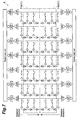
- the image acquisition device 1 performs imaging of the sample at a high magnification of 20x to 40x, for example. Therefore, the objective lens 25 has a field V which is small with respect to the sample S, whereby a region in which an image can be captured in one imaging operation also becomes small with respect to the sample S as illustrated in Fig. 3 . This makes it necessary for the field V of the objective lens 25 to be scanned with respect to the sample S in order to capture an image of the sample S as a whole.
- the image acquisition device 1 sets an image acquisition region 32 so as to include the sample S with respect to a sample container (e.g., a glass slide) holding the sample S and configures positions of a plurality of divisional regions 33 according to the image acquisition region 32 and the field V on the sample S of the objective lens 25. Then, an image of a part of the sample S corresponding to the divisional region 33 is captured, so as to acquire partial image data corresponding to the divisional region 33, and thereafter the stage drive unit 11 is driven such that the field V of the objective lens 25 is located at the next divisional region 33 to be subjected to imaging, where an image is captured again, so as to acquire partial image data.
- a sample container e.g., a glass slide
- the controller 13 drives the stage drive unit 11, so as to accelerate/decelerate the stage 2 when moving the field V on the sample S of the objective lens 25 from the divisional region 33 to the next divisional region 33 and stop the stage 2 at such a position that the field V on the sample S is at the next divisional region 33.
- the image acquisition device 1 repeatedly executes this operation, whereupon the image processing unit 14 combines thus obtained partial image data, so as to produce an image of the sample S as a whole.
- the controller 13 controls the objective lens 25 so as to move its field position with respect to the sample S along imaging lines Ln (where n is a natural number) constituted by a plurality of divisional regions 33. At this time, the controller 13 moves the stage 2 along the scan direction such that the field V on the sample S of the objective lens 25 is located at the next divisional region 33 to be subjected to imaging.
- bidirectional scanning in which scan directions are reversed between the imaging lines Ln adjacent to each other, for example, is employed as illustrated in Fig. 3 . Unidirectional scanning in which the same scan direction is used for all the imaging lines Ln may be employed as well. Also employable is random scanning in which the field position of the objective lens 25 moves randomly among the divisional regions 33.
- the objective lens drive unit 12 is constituted by a motor or actuator such as a stepping motor (pulse motor) or piezoelectric actuator, for example. Under the control of the controller 13, the objective lens drive unit 12 moves the objective lens 25 in the Z direction along the optical axis of the objective lens 25. This shifts the focal position of the objective lens 25 with respect to the sample S.
- a motor or actuator such as a stepping motor (pulse motor) or piezoelectric actuator, for example.
- the controller 13 is a part which controls respective operations of the image pickup element 6, stage drive unit 11, and objective lens drive unit 12. Specifically, the controller 13 causes the objective lens drive unit 12 to change the focal position (focal plane) of the objective lens 25 with respect to the sample S. At this time, the focal position of the objective lens 25 with respect to the sample S moves along one direction. Specifically, the controller 13 causes the objective lens drive unit 12 to change the position in the Z direction of the objective lens 25 with respect to the stage 2, thereby varying the distance between the stage 2 and objective lens 25.
- the controller 13 may cause the stage drive unit 11 to change the position in the Z direction of the stage 2 with respect to the objective lens 25, thereby varying the distance between the stage 2 and objective lens 25.
- the stage drive unit 11 serves as a drive unit for moving the focal position of the objective lens 25 with respect to the sample S, thereby fulfilling functions equivalent to those of this embodiment.
- the controller 13 also synchronizes movement of a predetermined part of the sample within the field V of the objective lens 25 caused by the stage drive unit 11 with the rolling readout of the image pickup element 6 such that each pixel column 31 of the image pickup element 6 is exposed (receives) an optical image of the predetermined part in the sample S.
- the movement of the stage 2 caused by the stage drive unit 11 is synchronized with the rolling readout of the image pickup element 6.
- the controller 13 may synchronize the movement of the predetermined part of the sample within the field V of the objective lens 25 caused by the objective lens drive unit 12 with the rolling readout of the image pickup element 6 such that each pixel column 31 of the image pickup element 6 is exposed to (receives) the optical image of the predetermined part in the sample S.
- the objective lens drive unit 12 serves as a drive unit for moving the field position of the objective lens 25 with respect to the sample S, thereby fulfilling functions equivalent to those of this embodiment.
- This embodiment employs a dynamic prefocus scheme in which focus information of the sample S in the next divisional region 33 to be subjected to imaging is acquired immediately before imaging.
- the focus information can be acquired while moving the field position of the objective lens 25 to the next divisional region to be subjected to imaging, whereby the sample S can be placed at an in-focus position at the time when the field V of the objective lens 25 is located at the next divisional region 33 to be subjected to imaging. Therefore, the imaging of the sample S can be executed rapidly.
- the controller 13 controls the stage drive unit 11 such that the sample S moves at a fixed speed within the field V of the objective lens 25 when the field V of the objective lens 25 shifts from one divisional region 33a to the next divisional region 33b.
- the controller 13 also controls the stage drive unit 11 and image pickup element 6 such that the moving direction of a focused image Sb of the optical image of the sample S on the light-receiving surface 6a of the image pickup element 6 and the readout direction of each pixel column 31 of the image pickup element 6 coincide with each other.
- the controller 13 may change the readout speed for the rolling readout according to the moving speed of the sample S within the field V of the objective lens 25.
- the position of a predetermined part Sa of the sample S used for acquiring focus information can be set according to a time from the start of movement of the field V of the objective lens 25 with respect to the sample S to the start of exposure of the pixel column 31.
- the controller 13 outputs a reset signal for starting exposure to the image pickup element 6 such as to start the exposure of the pixel column 31 after a lapse of a predetermined time since the field V of the objective lens 25 is moved.
- the controller 13 calculates the time from the start of movement of the field V of the objective lens 25 with respect to the sample S to the start of exposure of the pixel column 31 according to the position of the predetermined part Sa in the divisional region 33 and the moving speed (or acceleration of movement) of the sample S within the field V of the objective lens 25. Then, the controller 13 starts the exposure of the pixel column 31 after a lapse of the calculated time from the start of movement of the field V.
- the predetermined part Sa of the sample S is set in a region other than the end parts of the divisional regions 33 (regions abutting on boundaries of the divisional regions 33).
- the predetermined part Sa of the sample S is set so as to keep away from the boundaries of the divisional regions 33, whereby the start of exposure of the pixel column 31 is controlled according to the position of a region other than the end parts of the divisional region (regions abutting on the boundaries of the divisional regions 33) and the moving speed (or acceleration of movement) of the sample S within the field V of the objective lens 25.
- the exposure time in each pixel column 31 is set according to at least the width of the predetermined part Sa of the sample S in the scan direction and the moving speed of the predetermined part Sa of the sample S within the field V of the objective lens 25. More preferably, the magnification of the lightguide optical system 5 is also taken into consideration. This enables each pixel column 31 to be exposed to the optical image of the predetermined part Sa of the sample S.
- the position of the sample S within the field V of the objective lens 25 shifts as illustrated in Fig. 5(a) .
- the focal position of the objective lens 25 also changes as compared to that at the time T1 in such a direction that the gap between the sample S and objective lens 25 becomes narrower, for example.
- the focal position of the objective lens 25 with respect to the sample S moves along one direction.
- the focused image Sb of light from the predetermined part Sa of the sample S reaches the second pixel column 31, thereby starting exposure of the second pixel column 31.
- the readout of the first pixel column 31 is started at the timing when the focused image Sb of light from the predetermined part Sa of the sample S passes through the first pixel column 31.
- the position of the sample S within the field V of the objective lens 25 further shifts in the scan direction as illustrated in Fig. 6(a) .
- the focal position of the objective lens 25 also changes as compared to that at the time T1 in such a direction that the gap between the sample S and objective lens 25 becomes narrower.
- the focused image Sb of light from the predetermined part Sa of the sample S reaches the third pixel column 31, thereby starting exposure of the third pixel column 31.
- the readout of the second pixel column 31 is started at the timing when the focused image Sb of light from the predetermined part Sa of the sample S passes through the second pixel column 31.
- the readout of the first pixel column 31 ends at the same time when the readout of the second pixel column 31 is started.
- the movement of the predetermined part Sa of the sample S within the field V of the objective lens 25 and the rolling readout at the pixel column 31 are performed in the same procedure until a predetermined number of pixel columns is reached.
- Respective image data read out from the pixel columns 31 are sequentially outputted to the image processing unit 14. It is preferable for the image pickup element 6 to be able to switch readout directions of the rolling readout. This makes it easy for the moving direction of the focused image Sb of light from the sample S and the readout direction of each pixel column 31 of the image pickup element 6 to coincide with each other even when the scan direction of the field position of the objective lens 25 with respect to the sample S changes as in bidirectional scanning and random scanning.
- a plurality of pixel columns 31 constructing the light-receiving surface 6a of the image pickup element 6 may be separated into first and second pixel column groups 31 a, 31 b, each constituted by a plurality of pixel columns, the first and second pixel column groups 31a, 31b being read out separately from each other.
- the readout direction of the first pixel column group 31a and the readout direction of the second pixel column group 31b may be set opposite to each other, and the pixel column group used for acquiring focus information may be selected according to the scan direction.
- the first pixel column group 31 a is controlled such that pixel groups are sequentially read out from those at an end to those at the center
- the second pixel column group 31b is also controlled such that pixel groups are sequentially read out from those at an end to those at the center.
- the first pixel column group 31a may be controlled such that pixel groups are sequentially read out from those at the center to those at an end
- the first pixel column group 31a may also be controlled such that pixel groups are sequentially read out from those at the center to those at an end. This can adapt to bidirectional scanning.
- the first pixel column group 31a may be controlled such that pixel groups are sequentially read out from those at an end to those at the center, while the second pixel column group 31b may be controlled such that pixel groups are sequentially read out from those at the center to those at an end.
- the first and second pixel groups 31a, 31b are exposed to (receive) optical images of different sample positions, whereby focus information can be obtained at two positions at the same time.
- the image processing unit 14 is a part which combines partial image data captured by the image pickup element 6, so as to generate an observation image of the sample S.
- the image processing unit 14 sequentially receives the respective partial image data of the divisional regions 33 outputted from the image pickup element 6 and combines them, so as to generate an observation image of the sample S as a whole.
- the image processing unit 14 also functions as a focus calculation unit which calculates focus information of the sample S according to image data from the image pickup element 6. Specifically, the image processing unit 14 calculates the focus information of the sample S according to the respective image data from the pixel columns 31 of the image pickup element 6.
- An example of the focus information is such positional information in the Z direction of the objective lens 25 or stage 2 that the sample S is located at the focal position of the objective lens 25. Examples of such information include the position in the Z direction of the objective lens 25, the height (distance) of the objective lens 25 with respect to the sample S (stage 2), the position in the Z direction of the stage 2, and the height (distance) of the sample S (stage 2) with respect to the objective lens 25.
- the controller 13 synchronizes the movement of the predetermined part Sa of the sample S within the field V of the objective lens 25 caused by the stage drive unit 11 with the rolling readout of the image pickup element 6 such that each pixel column 31 of the image pickup element 6 is exposed to an optical image of the predetermined part Sa in the sample S, while causing the objective lens drive unit 12 to change the focal position of the objective lens 25. Therefore, in order for each pixel column 31 to be exposed to the optical image of the predetermined part Sa of the sample S, the image data from the image pickup element 6 obtained when the focal position is acquired includes contrast information at the time when the focal position of the objective lens 25 is changed at the predetermined part Sa (the same part) of the sample S.
- Fig. 8 is a diagram illustrating an example of contrast information processed by the image processing unit.
- the example illustrated in the diagram represents contrast values of image data from the first pixel column 31 to the n th pixel column 31 in the imaging region, in which the contrast value of the image data in the i th pixel column 31 is a peak value.
- the image processing unit 14 generates focus information.
- the contrast value the contrast value in a specific pixel in the pixels included in each pixel column 31 or an average value of contrast values in part or whole of the pixels included in each pixel column 31 may be used.
- Fig. 9 is a flowchart illustrating the operations of the image acquisition device.
- an image of the sample S is captured in one divisional region 33 (step S01), whereupon the field V of the objective lens 25 moves toward the next divisional region 33 (step S02).
- the focal position of the objective lens 25 is changed during the movement of the field V of the objective lens 25
- the movement of the predetermined part Sa of the sample S within the field V of the objective lens 25 is synchronized with the rolling readout of the image pickup element 6 such that each pixel column 31 of the image pickup element 6 is exposed to an optical image of the predetermined part Sa in the sample S after a lapse of a predetermined time (step S03).
- step S04 focus information is calculated according to respective contrast values of image data in the pixel columns.
- step S05 the focal position of the objective lens 25 with respect to the sample S is adjusted according to the calculated focus information, and an image of the sample S is captured in the next divisional region 33 after the field V of the objective lens 25 is located there.
- steps S01 to S05 is repeated until the imaging of the sample S is completed in all the divisional regions 33, whereupon the respective images of the divisional regions 33 are combined, so as to generate an observation image of the sample S as a whole.
- the image acquisition device 1 uses as the image pickup element 6 a two-dimensional image pickup element which is adapted to perform rolling readout while having a plurality of pixel columns 31.
- the rolling readout scheme which varies image data readout timings among the pixel columns 31 and thus may distort images when used for movable objects, is typically employed for objects which stand still.
- the image acquisition device 1 synchronizes the movement of the predetermined part Sa (the same part) of the sample S within the field V of the objective lens 25 with the rolling readout such that each pixel column 31 of the image pickup element 6 is exposed to an optical image of the predetermined part Sa in the sample S, while changing the focal position of the objective lens 25.
- image data from each pixel column 31 includes contrast information obtained when the focal position of the objective lens 25 is changed in the same part of the sample S, whereby the focus information can be calculated rapidly and accurately according to the contrast information.
- the image acquisition device 1 also controls the stage drive unit 11 such that the predetermined part Sa of the sample S is moved at a fixed speed within the field V of the objective lens 25. This can easily control the synchronization of the movement of the predetermined part Sa of the sample S within the field V of the objective lens 25 with the rolling readout.
- the predetermined part Sa of the sample S is set so as to be located in a region other than end parts of the divisional regions 33 in the image acquisition region 32 of the image pickup element 6.
- the predetermined part Sa of the sample S is more susceptible to acceleration at the time of being moved by the stage drive unit 11. Therefore, setting the predetermined part Sa of the sample S in a region other than end parts of the divisional regions 33 makes it possible to control the synchronization of the movement of the predetermined part Sa of the sample S within the field V of the objective lens 25 with the rolling readout more easily.
- the present invention is not limited to the above-mentioned embodiment.
- the objective lens drive unit 12 may be controlled so as to reciprocate the focal position of the objective lens in ascending and descending directions.
- the distance (gap) in the Z direction between the objective lens 25 and stage 2 is controlled so as to expand and contract repeatedly.
- the sample S is a tissue cell
- its thickness is about 10 ⁇ m, for example. Therefore, when the moving distance of the focal position of the objective lens 25 for each pixel column 31 is set to about 0.1 ⁇ m, contrast information can be acquired for the total thickness of the sample S by about 100 pixel columns.
- a two-dimensional image pickup element such as a CMOS image sensor has about several thousands of pixel columns, for example, whereby contrast information can be acquired a plurality of times during one frame. Consequently, by reciprocating the objective lens 25 in the height direction, focus information can be calculated for a plurality of predetermined regions of the sample S, which makes it possible to calculate focus information more accurately.
- a focus map scheme can also be employed. While the dynamic prefocus scheme acquires focus information between imaging of one divisional region 33 and imaging of the next divisional region 33, the focus map scheme acquires focus information in each divisional region 33 for the image acquisition region 32 or imaging line Ln before capturing an image of the sample S.
- the controller 13 controls the stage drive unit 11 such that the field V of the objective lens 25 moves at a fixed speed over a plurality of divisional regions 33.
- the moving direction of the focused image Sb of light from a predetermined position of the sample S and the readout direction of the image pickup element 6 are made to coincide with each other on the light-receiving surface 6a of the image pickup element 6.
- the readout of the next frame is started, which enables the predetermined part Sa of the sample S used for calculating the focus information to appear at fixed intervals, whereby at least one piece of focus information can be acquired in each divisional region 33.
- a focus map of the imaging line Ln or the sample S as a whole can be produced accurately by applying the method of least squares or the like to the focus information in each divisional region 33.
- Fig. 11 is a flowchart illustrating operations of the image acquisition device when producing a focus map.
- the stage drive unit 11 starts moving the stage 2, whereupon the field V of the objective lens 25 moves over a plurality of divisional regions 33 (step S11). It also synchronizes the movement of the predetermined part Sa of the sample S with the rolling readout of the image pickup element 6 such that each pixel column 31 of the image pickup element 6 is exposed to the focused image Sb of light of the predetermined part Sa in the sample S, while changing the focal position of the objective lens 25 so as to reciprocate it along the Z direction (step S12), and calculates focus information in each divisional region 33 (step S 13).
- step S14 it is determined whether or not the calculation of focus information is completely acquired for a desirable imaging line Ln (step S14); when the calculation of focus information is not completely acquired, the field V of the objective lens 25 is moved to the next imaging line Ln (step S15), and the processing of steps S01 to S03 is repeatedly executed.
- step S16 a focus map of the sample S is produced according to the focus information. Then, the image data of each divisional region 33 is acquired while locating the focal position of the objective lens 25 at the sample S according to the produced focus map.
- a focus map for this imaging line Ln may be produced, and the respective image data of the divisional regions 33 constituting the imaging line Ln may be acquired while locating the focal position of the objective lens 25 at the sample S according to the produced focus map.
- the focus map may be constituted by the focus information in each divisional region 33 itself instead of being produced by applying the method of least squares or the like to the focus information in each divisional region 33.
- 1 image acquisition device; 2: stage; 3: light source; 5: lightguide optical system; 6: image pickup element; 11: stage drive unit (first drive unit); 12: objective lens drive unit (second drive unit); 13: controller; 14: image processing unit (focus calculation unit); 25: objective lens; 31: pixel column; 32: image acquisition region; 33: divisional region; S: sample; Sa: predetermined part of the sample; V: objective lens field.
Applications Claiming Priority (2)
| Application Number | Priority Date | Filing Date | Title |
|---|---|---|---|
| JP2013094079 | 2013-04-26 | ||
| PCT/JP2014/061180 WO2014175219A1 (fr) | 2013-04-26 | 2014-04-21 | Dispositif d'acquisition d'image et procédé et système d'acquisition d'informations de mise au point pour un échantillon |
Publications (3)
| Publication Number | Publication Date |
|---|---|
| EP2990850A1 true EP2990850A1 (fr) | 2016-03-02 |
| EP2990850A4 EP2990850A4 (fr) | 2017-01-04 |
| EP2990850B1 EP2990850B1 (fr) | 2020-09-16 |
Family
ID=51791793
Family Applications (1)
| Application Number | Title | Priority Date | Filing Date |
|---|---|---|---|
| EP14788270.8A Active EP2990850B1 (fr) | 2013-04-26 | 2014-04-21 | Dispositif d'acquisition d'image et procédé et système d'acquisition d'informations de mise au point pour un échantillon |
Country Status (6)
| Country | Link |
|---|---|
| US (2) | US10330910B2 (fr) |
| EP (1) | EP2990850B1 (fr) |
| JP (1) | JP6433888B2 (fr) |
| CN (1) | CN105143954B (fr) |
| HU (1) | HUE052624T2 (fr) |
| WO (1) | WO2014175219A1 (fr) |
Cited By (1)
| Publication number | Priority date | Publication date | Assignee | Title |
|---|---|---|---|---|
| GB2544913A (en) * | 2013-02-01 | 2017-05-31 | Hamamatsu Photonics Kk | Image acquisition device and imaging device |
Families Citing this family (4)
| Publication number | Priority date | Publication date | Assignee | Title |
|---|---|---|---|---|
| JP6455829B2 (ja) * | 2013-04-01 | 2019-01-23 | キヤノン株式会社 | 画像処理装置、画像処理方法、およびプログラム |
| CN105143954B (zh) * | 2013-04-26 | 2018-06-19 | 浜松光子学株式会社 | 图像取得装置、取得试样的对准焦点信息的方法以及系统 |
| DE102016108226A1 (de) * | 2016-05-03 | 2017-11-09 | Carl Zeiss Microscopy Gmbh | Mikroskop |
| EP3614190A1 (fr) * | 2018-08-20 | 2020-02-26 | Till GmbH | Dispositif de microscope à objectif virtuel |
Family Cites Families (43)
| Publication number | Priority date | Publication date | Assignee | Title |
|---|---|---|---|---|
| JPH08320430A (ja) | 1995-05-23 | 1996-12-03 | Nikon Corp | 自動焦点検出装置 |
| US6677565B1 (en) | 1998-08-18 | 2004-01-13 | Veeco Tucson Inc. | High speed autofocus and tilt for an optical imaging system |
| WO2000056302A2 (fr) * | 1999-03-19 | 2000-09-28 | Parker Hughes Institute | Complexes de vanadium (iv) contenant un ligand catechinique, dotes d'une activite spermicide |
| US7518652B2 (en) | 2000-05-03 | 2009-04-14 | Aperio Technologies, Inc. | Method and apparatus for pre-focus in a linear array based slide scanner |
| KR20030028553A (ko) * | 2000-07-21 | 2003-04-08 | 더 트러스티스 오브 콜롬비아 유니버시티 인 더 시티 오브 뉴욕 | 이미지 모자이크 방법 및 장치 |
| US7243370B2 (en) * | 2001-06-14 | 2007-07-10 | Microsoft Corporation | Method and system for integrating security mechanisms into session initiation protocol request messages for client-proxy authentication |
| TW552803B (en) * | 2002-01-18 | 2003-09-11 | Nucam Corp | Image pickup apparatus and exposure control method therefor |
| EP1371939A1 (fr) * | 2002-05-15 | 2003-12-17 | Icos Vision Systems N.V. | Dispositif pour mesurer en trois dimensions la topographie superficielle d'un article |
| US20040051030A1 (en) * | 2002-09-17 | 2004-03-18 | Artur Olszak | Method and apparatus for acquiring images from a multiple axis imaging system |
| US7232980B2 (en) * | 2004-05-24 | 2007-06-19 | Hamamatsu Photonics K.K. | Microscope system |
| US7813579B2 (en) | 2004-05-24 | 2010-10-12 | Hamamatsu Photonics K.K. | Microscope system |
| CA2574343C (fr) * | 2004-07-23 | 2012-05-01 | Paul Donders | Procede et appareil pour microscopie confocale a fluorescence |
| WO2006098443A1 (fr) | 2005-03-17 | 2006-09-21 | Hamamatsu Photonics K.K. | Dispositif de capture d'images microscopiques |
| JP2006343573A (ja) | 2005-06-09 | 2006-12-21 | Olympus Corp | 顕微鏡システム、観察方法および観察プログラム |
| US7297910B2 (en) | 2005-12-30 | 2007-11-20 | General Electric Company | System and method for utilizing an autofocus feature in an automated microscope |
| AU2007215302A1 (en) | 2006-02-10 | 2007-08-23 | Hologic, Inc. | Method and apparatus and computer program product for collecting digital image data from microscope media-based specimens |
| JP2007232930A (ja) * | 2006-02-28 | 2007-09-13 | Toshiba Corp | フォーカス合わせ装置及びフォーカス合わせ方法 |
| JP4917331B2 (ja) | 2006-03-01 | 2012-04-18 | 浜松ホトニクス株式会社 | 画像取得装置、画像取得方法、及び画像取得プログラム |
| JP2008052140A (ja) | 2006-08-25 | 2008-03-06 | Olympus Corp | 観察装置 |
| JP2008221299A (ja) * | 2007-03-14 | 2008-09-25 | Hitachi Via Mechanics Ltd | レーザ加工装置 |
| JP4863955B2 (ja) | 2007-09-10 | 2012-01-25 | 三洋電機株式会社 | 自動焦点調節装置 |
| US8153949B2 (en) * | 2008-12-18 | 2012-04-10 | Palo Alto Research Center Incorporated | Obtaining sensing results indicating time variation |
| US8743195B2 (en) | 2008-10-24 | 2014-06-03 | Leica Biosystems Imaging, Inc. | Whole slide fluorescence scanner |
| JP2010256530A (ja) | 2009-04-23 | 2010-11-11 | Olympus Corp | 顕微鏡装置 |
| JP2011081211A (ja) * | 2009-10-07 | 2011-04-21 | Olympus Corp | 顕微鏡システム |
| EP2618199A1 (fr) | 2009-12-30 | 2013-07-24 | Koninklijke Philips Electronics N.V. | Capteur autofocus automatique |
| US10061108B2 (en) | 2010-05-18 | 2018-08-28 | Koninklijke Philips N.V. | Autofocus imaging for a microscope |
| US9041930B1 (en) * | 2010-05-20 | 2015-05-26 | Kla-Tencor Corporation | Digital pathology system |
| CN103038692B (zh) | 2010-06-24 | 2015-12-16 | 皇家飞利浦电子股份有限公司 | 基于差分测量的自动聚焦 |
| WO2012002893A1 (fr) * | 2010-06-30 | 2012-01-05 | Ge Healthcare Bio-Sciences Corp | Système de synchronisation pour microscope d'imagerie à balayage linéaire |
| JP2012073285A (ja) | 2010-09-27 | 2012-04-12 | Olympus Corp | 撮像方法および顕微鏡装置 |
| JP5673002B2 (ja) * | 2010-11-15 | 2015-02-18 | ソニー株式会社 | 焦点位置情報検出装置、顕微鏡装置及び焦点位置情報検出方法 |
| JP5751986B2 (ja) * | 2010-12-08 | 2015-07-22 | キヤノン株式会社 | 画像生成装置 |
| JP5668227B2 (ja) * | 2011-02-17 | 2015-02-12 | 株式会社ミツトヨ | 画像測定装置 |
| JP5197785B2 (ja) * | 2011-03-30 | 2013-05-15 | キヤノン株式会社 | 画像処理装置、撮像システム、画像処理システム |
| GB201113071D0 (en) * | 2011-07-29 | 2011-09-14 | Ffei Ltd | Method and apparatus for image scanning |
| JP5705096B2 (ja) * | 2011-12-02 | 2015-04-22 | キヤノン株式会社 | 画像処理装置及び画像処理方法 |
| WO2013165576A1 (fr) * | 2012-05-02 | 2013-11-07 | Aperio Technologies, Inc. | Mise au point en temps réel en imagerie à balayage linéaire |
| US9488823B2 (en) * | 2012-06-07 | 2016-11-08 | Complete Genomics, Inc. | Techniques for scanned illumination |
| US9632303B2 (en) * | 2012-11-26 | 2017-04-25 | Osaka University | Optical microscope, and autofocus device for optical microscope |
| US10114206B2 (en) | 2013-02-25 | 2018-10-30 | Huron Technologies International Inc. | Microscopy slide scanner with variable magnification |
| CN105143954B (zh) * | 2013-04-26 | 2018-06-19 | 浜松光子学株式会社 | 图像取得装置、取得试样的对准焦点信息的方法以及系统 |
| US9134523B2 (en) | 2013-07-19 | 2015-09-15 | Hong Kong Applied Science and Technology Research Institute Company Limited | Predictive focusing for image scanning systems |
-
2014
- 2014-04-21 CN CN201480023712.3A patent/CN105143954B/zh active Active
- 2014-04-21 HU HUE14788270A patent/HUE052624T2/hu unknown
- 2014-04-21 JP JP2015513748A patent/JP6433888B2/ja active Active
- 2014-04-21 US US14/786,576 patent/US10330910B2/en active Active
- 2014-04-21 EP EP14788270.8A patent/EP2990850B1/fr active Active
- 2014-04-21 WO PCT/JP2014/061180 patent/WO2014175219A1/fr active Application Filing
-
2019
- 2019-05-08 US US16/407,093 patent/US10598916B2/en active Active
Cited By (5)
| Publication number | Priority date | Publication date | Assignee | Title |
|---|---|---|---|---|
| GB2544913A (en) * | 2013-02-01 | 2017-05-31 | Hamamatsu Photonics Kk | Image acquisition device and imaging device |
| GB2544913B (en) * | 2013-02-01 | 2017-11-15 | Hamamatsu Photonics Kk | Image acquisition device, and imaging device |
| US10142566B2 (en) | 2013-02-01 | 2018-11-27 | Hamamatsu Photonics K.K. | Rolling readout type camera and imaging method for using the same |
| US10362245B2 (en) | 2013-02-01 | 2019-07-23 | Hamamatsu Photonics K.K. | Imaging device that performs rolling readout of pixel rows to acquire an image of an object |
| US10602087B2 (en) | 2013-02-01 | 2020-03-24 | Hamamatsu Photonics K.K | Image acquisition device, and imaging device |
Also Published As
| Publication number | Publication date |
|---|---|
| US10330910B2 (en) | 2019-06-25 |
| EP2990850B1 (fr) | 2020-09-16 |
| US20190265457A1 (en) | 2019-08-29 |
| WO2014175219A1 (fr) | 2014-10-30 |
| CN105143954A (zh) | 2015-12-09 |
| US10598916B2 (en) | 2020-03-24 |
| HUE052624T2 (hu) | 2021-05-28 |
| JP6433888B2 (ja) | 2018-12-05 |
| EP2990850A4 (fr) | 2017-01-04 |
| JPWO2014175219A1 (ja) | 2017-02-23 |
| US20160077322A1 (en) | 2016-03-17 |
| CN105143954B (zh) | 2018-06-19 |
Similar Documents
| Publication | Publication Date | Title |
|---|---|---|
| US10598916B2 (en) | Image acquisition device and method and system for acquiring focusing information for specimen | |
| US10348954B2 (en) | Image acquisition device and method and system for creating focus map for specimen | |
| US9661212B2 (en) | Image acquisition device and focusing method for image acquisition device | |
| US20220128807A1 (en) | Image acquisition device and image acquisition method | |
| JP2005275199A (ja) | 3次元共焦点顕微鏡システム | |
| CN105683806B (zh) | 图像取得装置以及图像取得装置的图像取得方法 | |
| EP2947488A1 (fr) | Dispositif d'acquisition d'images et procédé de mise au point pour dispositif d'acquisition d'images | |
| JP6076205B2 (ja) | 画像取得装置及び画像取得装置のフォーカス方法 | |
| KR102058780B1 (ko) | 라인 스캐닝 방식의 공초점 현미경에서의 자동초점조절 방법 및 장치 | |
| JP5770958B1 (ja) | 画像取得装置及び撮像装置 | |
| JP6240056B2 (ja) | 画像取得装置及び撮像装置 | |
| JP6010506B2 (ja) | 画像取得装置及び画像取得装置のフォーカス方法 |
Legal Events
| Date | Code | Title | Description |
|---|---|---|---|
| PUAI | Public reference made under article 153(3) epc to a published international application that has entered the european phase |
Free format text: ORIGINAL CODE: 0009012 |
|
| 17P | Request for examination filed |
Effective date: 20151020 |
|
| AK | Designated contracting states |
Kind code of ref document: A1 Designated state(s): AL AT BE BG CH CY CZ DE DK EE ES FI FR GB GR HR HU IE IS IT LI LT LU LV MC MK MT NL NO PL PT RO RS SE SI SK SM TR |
|
| AX | Request for extension of the european patent |
Extension state: BA ME |
|
| DAX | Request for extension of the european patent (deleted) | ||
| A4 | Supplementary search report drawn up and despatched |
Effective date: 20161202 |
|
| RIC1 | Information provided on ipc code assigned before grant |
Ipc: G02B 7/28 20060101ALI20161128BHEP Ipc: G02B 21/36 20060101AFI20161128BHEP Ipc: G02B 7/36 20060101ALI20161128BHEP Ipc: G02B 21/24 20060101ALI20161128BHEP Ipc: H04N 5/232 20060101ALI20161128BHEP |
|
| RIN1 | Information on inventor provided before grant (corrected) |
Inventor name: OKUGAWA, MASATOSHI Inventor name: IWASE, FUMIO |
|
| GRAP | Despatch of communication of intention to grant a patent |
Free format text: ORIGINAL CODE: EPIDOSNIGR1 |
|
| STAA | Information on the status of an ep patent application or granted ep patent |
Free format text: STATUS: GRANT OF PATENT IS INTENDED |
|
| INTG | Intention to grant announced |
Effective date: 20200417 |
|
| GRAS | Grant fee paid |
Free format text: ORIGINAL CODE: EPIDOSNIGR3 |
|
| GRAA | (expected) grant |
Free format text: ORIGINAL CODE: 0009210 |
|
| STAA | Information on the status of an ep patent application or granted ep patent |
Free format text: STATUS: THE PATENT HAS BEEN GRANTED |
|
| AK | Designated contracting states |
Kind code of ref document: B1 Designated state(s): AL AT BE BG CH CY CZ DE DK EE ES FI FR GB GR HR HU IE IS IT LI LT LU LV MC MK MT NL NO PL PT RO RS SE SI SK SM TR |
|
| REG | Reference to a national code |
Ref country code: GB Ref legal event code: FG4D |
|
| REG | Reference to a national code |
Ref country code: CH Ref legal event code: EP |
|
| REG | Reference to a national code |
Ref country code: DE Ref legal event code: R096 Ref document number: 602014070279 Country of ref document: DE |
|
| REG | Reference to a national code |
Ref country code: IE Ref legal event code: FG4D |
|
| REG | Reference to a national code |
Ref country code: AT Ref legal event code: REF Ref document number: 1314674 Country of ref document: AT Kind code of ref document: T Effective date: 20201015 |
|
| REG | Reference to a national code |
Ref country code: SE Ref legal event code: TRGR |
|
| PG25 | Lapsed in a contracting state [announced via postgrant information from national office to epo] |
Ref country code: BG Free format text: LAPSE BECAUSE OF FAILURE TO SUBMIT A TRANSLATION OF THE DESCRIPTION OR TO PAY THE FEE WITHIN THE PRESCRIBED TIME-LIMIT Effective date: 20201216 Ref country code: FI Free format text: LAPSE BECAUSE OF FAILURE TO SUBMIT A TRANSLATION OF THE DESCRIPTION OR TO PAY THE FEE WITHIN THE PRESCRIBED TIME-LIMIT Effective date: 20200916 Ref country code: HR Free format text: LAPSE BECAUSE OF FAILURE TO SUBMIT A TRANSLATION OF THE DESCRIPTION OR TO PAY THE FEE WITHIN THE PRESCRIBED TIME-LIMIT Effective date: 20200916 Ref country code: GR Free format text: LAPSE BECAUSE OF FAILURE TO SUBMIT A TRANSLATION OF THE DESCRIPTION OR TO PAY THE FEE WITHIN THE PRESCRIBED TIME-LIMIT Effective date: 20201217 Ref country code: NO Free format text: LAPSE BECAUSE OF FAILURE TO SUBMIT A TRANSLATION OF THE DESCRIPTION OR TO PAY THE FEE WITHIN THE PRESCRIBED TIME-LIMIT Effective date: 20201216 |
|
| REG | Reference to a national code |
Ref country code: AT Ref legal event code: MK05 Ref document number: 1314674 Country of ref document: AT Kind code of ref document: T Effective date: 20200916 |
|
| REG | Reference to a national code |
Ref country code: NL Ref legal event code: MP Effective date: 20200916 |
|
| PG25 | Lapsed in a contracting state [announced via postgrant information from national office to epo] |
Ref country code: RS Free format text: LAPSE BECAUSE OF FAILURE TO SUBMIT A TRANSLATION OF THE DESCRIPTION OR TO PAY THE FEE WITHIN THE PRESCRIBED TIME-LIMIT Effective date: 20200916 Ref country code: LV Free format text: LAPSE BECAUSE OF FAILURE TO SUBMIT A TRANSLATION OF THE DESCRIPTION OR TO PAY THE FEE WITHIN THE PRESCRIBED TIME-LIMIT Effective date: 20200916 |
|
| REG | Reference to a national code |
Ref country code: LT Ref legal event code: MG4D |
|
| PG25 | Lapsed in a contracting state [announced via postgrant information from national office to epo] |
Ref country code: CZ Free format text: LAPSE BECAUSE OF FAILURE TO SUBMIT A TRANSLATION OF THE DESCRIPTION OR TO PAY THE FEE WITHIN THE PRESCRIBED TIME-LIMIT Effective date: 20200916 Ref country code: EE Free format text: LAPSE BECAUSE OF FAILURE TO SUBMIT A TRANSLATION OF THE DESCRIPTION OR TO PAY THE FEE WITHIN THE PRESCRIBED TIME-LIMIT Effective date: 20200916 Ref country code: SM Free format text: LAPSE BECAUSE OF FAILURE TO SUBMIT A TRANSLATION OF THE DESCRIPTION OR TO PAY THE FEE WITHIN THE PRESCRIBED TIME-LIMIT Effective date: 20200916 Ref country code: RO Free format text: LAPSE BECAUSE OF FAILURE TO SUBMIT A TRANSLATION OF THE DESCRIPTION OR TO PAY THE FEE WITHIN THE PRESCRIBED TIME-LIMIT Effective date: 20200916 Ref country code: LT Free format text: LAPSE BECAUSE OF FAILURE TO SUBMIT A TRANSLATION OF THE DESCRIPTION OR TO PAY THE FEE WITHIN THE PRESCRIBED TIME-LIMIT Effective date: 20200916 Ref country code: PT Free format text: LAPSE BECAUSE OF FAILURE TO SUBMIT A TRANSLATION OF THE DESCRIPTION OR TO PAY THE FEE WITHIN THE PRESCRIBED TIME-LIMIT Effective date: 20210118 Ref country code: NL Free format text: LAPSE BECAUSE OF FAILURE TO SUBMIT A TRANSLATION OF THE DESCRIPTION OR TO PAY THE FEE WITHIN THE PRESCRIBED TIME-LIMIT Effective date: 20200916 |
|
| REG | Reference to a national code |
Ref country code: HU Ref legal event code: AG4A Ref document number: E052624 Country of ref document: HU |
|
| PG25 | Lapsed in a contracting state [announced via postgrant information from national office to epo] |
Ref country code: AT Free format text: LAPSE BECAUSE OF FAILURE TO SUBMIT A TRANSLATION OF THE DESCRIPTION OR TO PAY THE FEE WITHIN THE PRESCRIBED TIME-LIMIT Effective date: 20200916 Ref country code: AL Free format text: LAPSE BECAUSE OF FAILURE TO SUBMIT A TRANSLATION OF THE DESCRIPTION OR TO PAY THE FEE WITHIN THE PRESCRIBED TIME-LIMIT Effective date: 20200916 Ref country code: ES Free format text: LAPSE BECAUSE OF FAILURE TO SUBMIT A TRANSLATION OF THE DESCRIPTION OR TO PAY THE FEE WITHIN THE PRESCRIBED TIME-LIMIT Effective date: 20200916 Ref country code: IS Free format text: LAPSE BECAUSE OF FAILURE TO SUBMIT A TRANSLATION OF THE DESCRIPTION OR TO PAY THE FEE WITHIN THE PRESCRIBED TIME-LIMIT Effective date: 20210116 Ref country code: PL Free format text: LAPSE BECAUSE OF FAILURE TO SUBMIT A TRANSLATION OF THE DESCRIPTION OR TO PAY THE FEE WITHIN THE PRESCRIBED TIME-LIMIT Effective date: 20200916 |
|
| REG | Reference to a national code |
Ref country code: DE Ref legal event code: R097 Ref document number: 602014070279 Country of ref document: DE |
|
| PG25 | Lapsed in a contracting state [announced via postgrant information from national office to epo] |
Ref country code: SK Free format text: LAPSE BECAUSE OF FAILURE TO SUBMIT A TRANSLATION OF THE DESCRIPTION OR TO PAY THE FEE WITHIN THE PRESCRIBED TIME-LIMIT Effective date: 20200916 |
|
| PLBE | No opposition filed within time limit |
Free format text: ORIGINAL CODE: 0009261 |
|
| STAA | Information on the status of an ep patent application or granted ep patent |
Free format text: STATUS: NO OPPOSITION FILED WITHIN TIME LIMIT |
|
| 26N | No opposition filed |
Effective date: 20210617 |
|
| PG25 | Lapsed in a contracting state [announced via postgrant information from national office to epo] |
Ref country code: DK Free format text: LAPSE BECAUSE OF FAILURE TO SUBMIT A TRANSLATION OF THE DESCRIPTION OR TO PAY THE FEE WITHIN THE PRESCRIBED TIME-LIMIT Effective date: 20200916 Ref country code: SI Free format text: LAPSE BECAUSE OF FAILURE TO SUBMIT A TRANSLATION OF THE DESCRIPTION OR TO PAY THE FEE WITHIN THE PRESCRIBED TIME-LIMIT Effective date: 20200916 |
|
| PG25 | Lapsed in a contracting state [announced via postgrant information from national office to epo] |
Ref country code: IT Free format text: LAPSE BECAUSE OF FAILURE TO SUBMIT A TRANSLATION OF THE DESCRIPTION OR TO PAY THE FEE WITHIN THE PRESCRIBED TIME-LIMIT Effective date: 20200916 |
|
| PG25 | Lapsed in a contracting state [announced via postgrant information from national office to epo] |
Ref country code: MC Free format text: LAPSE BECAUSE OF FAILURE TO SUBMIT A TRANSLATION OF THE DESCRIPTION OR TO PAY THE FEE WITHIN THE PRESCRIBED TIME-LIMIT Effective date: 20200916 |
|
| PG25 | Lapsed in a contracting state [announced via postgrant information from national office to epo] |
Ref country code: LU Free format text: LAPSE BECAUSE OF NON-PAYMENT OF DUE FEES Effective date: 20210421 |
|
| REG | Reference to a national code |
Ref country code: BE Ref legal event code: MM Effective date: 20210430 |
|
| PG25 | Lapsed in a contracting state [announced via postgrant information from national office to epo] |
Ref country code: LI Free format text: LAPSE BECAUSE OF NON-PAYMENT OF DUE FEES Effective date: 20210430 Ref country code: CH Free format text: LAPSE BECAUSE OF NON-PAYMENT OF DUE FEES Effective date: 20210430 |
|
| PG25 | Lapsed in a contracting state [announced via postgrant information from national office to epo] |
Ref country code: IE Free format text: LAPSE BECAUSE OF NON-PAYMENT OF DUE FEES Effective date: 20210421 |
|
| PG25 | Lapsed in a contracting state [announced via postgrant information from national office to epo] |
Ref country code: IS Free format text: LAPSE BECAUSE OF FAILURE TO SUBMIT A TRANSLATION OF THE DESCRIPTION OR TO PAY THE FEE WITHIN THE PRESCRIBED TIME-LIMIT Effective date: 20210116 |
|
| PG25 | Lapsed in a contracting state [announced via postgrant information from national office to epo] |
Ref country code: BE Free format text: LAPSE BECAUSE OF NON-PAYMENT OF DUE FEES Effective date: 20210430 |
|
| PGFP | Annual fee paid to national office [announced via postgrant information from national office to epo] |
Ref country code: FR Payment date: 20230309 Year of fee payment: 10 |
|
| PGFP | Annual fee paid to national office [announced via postgrant information from national office to epo] |
Ref country code: SE Payment date: 20230227 Year of fee payment: 10 Ref country code: GB Payment date: 20230302 Year of fee payment: 10 |
|
| P01 | Opt-out of the competence of the unified patent court (upc) registered |
Effective date: 20230517 |
|
| PG25 | Lapsed in a contracting state [announced via postgrant information from national office to epo] |
Ref country code: CY Free format text: LAPSE BECAUSE OF FAILURE TO SUBMIT A TRANSLATION OF THE DESCRIPTION OR TO PAY THE FEE WITHIN THE PRESCRIBED TIME-LIMIT Effective date: 20200916 |
|
| PGFP | Annual fee paid to national office [announced via postgrant information from national office to epo] |
Ref country code: DE Payment date: 20230228 Year of fee payment: 10 |
|
| PGFP | Annual fee paid to national office [announced via postgrant information from national office to epo] |
Ref country code: HU Payment date: 20230320 Year of fee payment: 10 |