EP2990823A1 - Radarsensor, insbesondere für ein kraftfahrzeug, und kraftfahrzeug - Google Patents
Radarsensor, insbesondere für ein kraftfahrzeug, und kraftfahrzeug Download PDFInfo
- Publication number
- EP2990823A1 EP2990823A1 EP15001561.8A EP15001561A EP2990823A1 EP 2990823 A1 EP2990823 A1 EP 2990823A1 EP 15001561 A EP15001561 A EP 15001561A EP 2990823 A1 EP2990823 A1 EP 2990823A1
- Authority
- EP
- European Patent Office
- Prior art keywords
- radar
- radome
- radar sensor
- movement device
- motor vehicle
- Prior art date
- Legal status (The legal status is an assumption and is not a legal conclusion. Google has not performed a legal analysis and makes no representation as to the accuracy of the status listed.)
- Granted
Links
Images

Classifications
-
- G—PHYSICS
- G01—MEASURING; TESTING
- G01S—RADIO DIRECTION-FINDING; RADIO NAVIGATION; DETERMINING DISTANCE OR VELOCITY BY USE OF RADIO WAVES; LOCATING OR PRESENCE-DETECTING BY USE OF THE REFLECTION OR RERADIATION OF RADIO WAVES; ANALOGOUS ARRANGEMENTS USING OTHER WAVES
- G01S7/00—Details of systems according to groups G01S13/00, G01S15/00, G01S17/00
- G01S7/02—Details of systems according to groups G01S13/00, G01S15/00, G01S17/00 of systems according to group G01S13/00
- G01S7/03—Details of HF subsystems specially adapted therefor, e.g. common to transmitter and receiver
- G01S7/032—Constructional details for solid-state radar subsystems
-
- G—PHYSICS
- G01—MEASURING; TESTING
- G01S—RADIO DIRECTION-FINDING; RADIO NAVIGATION; DETERMINING DISTANCE OR VELOCITY BY USE OF RADIO WAVES; LOCATING OR PRESENCE-DETECTING BY USE OF THE REFLECTION OR RERADIATION OF RADIO WAVES; ANALOGOUS ARRANGEMENTS USING OTHER WAVES
- G01S13/00—Systems using the reflection or reradiation of radio waves, e.g. radar systems; Analogous systems using reflection or reradiation of waves whose nature or wavelength is irrelevant or unspecified
- G01S13/88—Radar or analogous systems specially adapted for specific applications
- G01S13/93—Radar or analogous systems specially adapted for specific applications for anti-collision purposes
- G01S13/931—Radar or analogous systems specially adapted for specific applications for anti-collision purposes of land vehicles
-
- H—ELECTRICITY
- H01—ELECTRIC ELEMENTS
- H01Q—ANTENNAS, i.e. RADIO AERIALS
- H01Q1/00—Details of, or arrangements associated with, antennas
- H01Q1/27—Adaptation for use in or on movable bodies
- H01Q1/32—Adaptation for use in or on road or rail vehicles
- H01Q1/3208—Adaptation for use in or on road or rail vehicles characterised by the application wherein the antenna is used
- H01Q1/3233—Adaptation for use in or on road or rail vehicles characterised by the application wherein the antenna is used particular used as part of a sensor or in a security system, e.g. for automotive radar, navigation systems
-
- H—ELECTRICITY
- H01—ELECTRIC ELEMENTS
- H01Q—ANTENNAS, i.e. RADIO AERIALS
- H01Q3/00—Arrangements for changing or varying the orientation or the shape of the directional pattern of the waves radiated from an antenna or antenna system
- H01Q3/12—Arrangements for changing or varying the orientation or the shape of the directional pattern of the waves radiated from an antenna or antenna system using mechanical relative movement between primary active elements and secondary devices of antennas or antenna systems
- H01Q3/14—Arrangements for changing or varying the orientation or the shape of the directional pattern of the waves radiated from an antenna or antenna system using mechanical relative movement between primary active elements and secondary devices of antennas or antenna systems for varying the relative position of primary active element and a refracting or diffracting device
-
- G—PHYSICS
- G01—MEASURING; TESTING
- G01S—RADIO DIRECTION-FINDING; RADIO NAVIGATION; DETERMINING DISTANCE OR VELOCITY BY USE OF RADIO WAVES; LOCATING OR PRESENCE-DETECTING BY USE OF THE REFLECTION OR RERADIATION OF RADIO WAVES; ANALOGOUS ARRANGEMENTS USING OTHER WAVES
- G01S13/00—Systems using the reflection or reradiation of radio waves, e.g. radar systems; Analogous systems using reflection or reradiation of waves whose nature or wavelength is irrelevant or unspecified
- G01S13/88—Radar or analogous systems specially adapted for specific applications
- G01S13/93—Radar or analogous systems specially adapted for specific applications for anti-collision purposes
- G01S13/931—Radar or analogous systems specially adapted for specific applications for anti-collision purposes of land vehicles
- G01S2013/9327—Sensor installation details
- G01S2013/93271—Sensor installation details in the front of the vehicles
-
- G—PHYSICS
- G01—MEASURING; TESTING
- G01S—RADIO DIRECTION-FINDING; RADIO NAVIGATION; DETERMINING DISTANCE OR VELOCITY BY USE OF RADIO WAVES; LOCATING OR PRESENCE-DETECTING BY USE OF THE REFLECTION OR RERADIATION OF RADIO WAVES; ANALOGOUS ARRANGEMENTS USING OTHER WAVES
- G01S13/00—Systems using the reflection or reradiation of radio waves, e.g. radar systems; Analogous systems using reflection or reradiation of waves whose nature or wavelength is irrelevant or unspecified
- G01S13/88—Radar or analogous systems specially adapted for specific applications
- G01S13/93—Radar or analogous systems specially adapted for specific applications for anti-collision purposes
- G01S13/931—Radar or analogous systems specially adapted for specific applications for anti-collision purposes of land vehicles
- G01S2013/9327—Sensor installation details
- G01S2013/93272—Sensor installation details in the back of the vehicles
-
- G—PHYSICS
- G01—MEASURING; TESTING
- G01S—RADIO DIRECTION-FINDING; RADIO NAVIGATION; DETERMINING DISTANCE OR VELOCITY BY USE OF RADIO WAVES; LOCATING OR PRESENCE-DETECTING BY USE OF THE REFLECTION OR RERADIATION OF RADIO WAVES; ANALOGOUS ARRANGEMENTS USING OTHER WAVES
- G01S7/00—Details of systems according to groups G01S13/00, G01S15/00, G01S17/00
- G01S7/02—Details of systems according to groups G01S13/00, G01S15/00, G01S17/00 of systems according to group G01S13/00
- G01S7/027—Constructional details of housings, e.g. form, type, material or ruggedness
- G01S7/028—Miniaturisation, e.g. surface mounted device [SMD] packaging or housings
Definitions
- the invention relates to a radar sensor, in particular for a motor vehicle, comprising a CMOS chip, an antenna arrangement and a radome, which is arranged on a printed circuit board and realizes at least one radar transceiver.
- the invention relates to a motor vehicle with such a radar sensor.
- radar sensors are nowadays usually used as environment sensors for a medium and large distance range in order to determine other road users or larger objects in distance, angle and relative speed.
- Such radar data can enter into environmental models or even be made available to vehicle systems directly.
- Benefits of radar data draw in the prior art, for example, longitudinal guidance systems, such as ACC, or security systems.
- Radar sensors of conventional design usually have a greater extent and are rather clunky, after the antennas and the electronic components required directly on the antenna, so the radar front end, are integrated in a housing. Mainly the electronic components thereby form the radar transceiver, which contains a frequency control (usually comprising a phase-locked loop - PLL), mixing devices, a low noise amplifier (LNA) and the like, but often also control modules and digital signal processing components are realized close to the antenna, for example already processed Sensor data, such as object lists, on a connected bus, such as a CAN bus to give.
- a frequency control usually comprising a phase-locked loop - PLL
- mixing devices usually comprising a phase-locked loop - PLL
- LNA low noise amplifier
- CMOS complementary metal-oxide-semiconductor
- RF CMOS complementary metal-oxide-semiconductor
- a very low cost small radar sensor is possible, which can meet the space requirements significantly better and due to the short signal paths also has a very low signal-to-noise ratio and for high frequencies and larger, variable frequency bandwidths is suitable. Therefore, such small-sized radar sensors can also be used for short-range applications, for example in the range of 30 cm to 10 m.
- CMOS transceiver chip and / or a package with CMOS transceiver chip and antenna on a common circuit board with a digital signal processing processor (DSP processor) or the functions of the signal processing processor in the CMOS Integrate transceiver chip. Similar integration is possible for control functions.
- DSP processor digital signal processing processor
- radome plays an important role.
- the term radome (short for "radar dome") is usually referred to the cover that protects the antenna assembly of the radar sensor from external mechanical and chemical influences, such as wind or rain.
- the radome is usually made permeable to radar waves, thus consists of a suitable high-frequency material (RF material). Due to the shape of the radome, detection properties of the radar sensor can be influenced, in particular the opening angle of the detection area and the range of the radar sensor. If, for example, a completely flat radome is used, the result is a large aperture angle, but a reduced range, because the two interfaces involved do not cause any actual influence on the radar signal. However, if, for example, a hemispherical bulged radome is used, the curved outer interface results in a lensing effect that, while reducing the aperture angle, increases the range because the radar beam is focused to a smaller area.
- the radar sensor is operated either with a flat or with a hemispherical radome, which is assigned to the corresponding radar front end.
- the focus is placed on a radar sensor either on a greater range or on a larger opening angle.
- the invention is therefore based on the object of specifying a radar sensor which converts different detection properties in a simple manner.
- the particular one-piece radome has at least two differently acting radar optical sections and a movement device for moving the radome in the individual radar optical sections assigned modulated positions in which the antenna array radiates through the respective radar optical section, is provided.
- the radar optical section covers the antenna arrangement in the direction of emission, resulting in the radiation characteristics defined by the radar optical section.
- CMOS technology ie in particular the existence of packages that contain the antenna arrangement and a CMOS chip that realizes at least the radar transceiver and can be realized on a printed circuit board, by a small-sized radar sensor to provide him with a movable radome without too much construction effort and cost.
- the radome has radar optics sections that can define different detection properties for the radar sensor, wherein preferably two radar optics sections are provided, but also more than two radar optics sections are conceivable.
- at least the portion of the radome containing the radar optical sections is made in one piece, which is easily possible with the small required size.
- a movable, in particular displaceable, multifunctional radome is present as part of the housing of the radar sensor, so that the radar sensor can be operated with different detection properties that are defined by the radar optical sections without any change in its other operation.
- different operating modes are therefore available for the radar sensor in order to adjust the opening angle and the range of the sensor without the actual radar front end or the antenna arrangement having to be changed.
- the radome may include a far-field detection radar optics section and a near-field detection radar optics section, although other configurations are contemplated.
- the radome or at least the proportion that realizes the radar optics sections is massive, that is, it consists entirely of a material permeable to radar radiation, so that the different detection properties are realized by the boundary surfaces of the radome.
- the radome or at least the proportion that realizes the radar optics sections is massive, that is, it consists entirely of a material permeable to radar radiation, so that the different detection properties are realized by the boundary surfaces of the radome.
- the radome has at least one flat radar optical section and at least one radar optical section bulged outwards and exerting a lens effect on the radar radiation.
- the curvature of the curved Radaroptikabites be particularly hemispherical.
- the radome in the first radar optical section can exert a lensing effect with the bulge, thus reducing the opening angle of the detection area, but increasing the range.
- a radar optical section can be created which is flat and thus realizes a larger opening angle and a reduced range.
- the radar optical sections mentioned here are of course to be understood by way of example; in principle, other shapes, for example inwardly curved surfaces, are also conceivable.
- the radome can expediently consist of a high-frequency material, in particular comprising polypropylene. It is essential here that the high-frequency material for radar radiation is as permeable as possible, and therefore has a high transmission coefficient.
- a suitable material polypropylene or a polypropylene mixture has proven that is often used for bumpers of motor vehicles.
- the radome is made in a casting process.
- the radome preferably integral at least in the proportion of Radaroptikabitese, which, as shown, preferably anyway solid without cavities, can be prepared by providing a suitable shape in a casting process in a simple and cost-effective manner.
- a particularly expedient embodiment of the present invention provides that the antenna arrangement is realized in a package with the CMOS chip. Then an extremely small-sized radar sensor is given, which also realizes short signal paths and thus avoids interference effects by longer signal paths. This results in an excellent signal-to-noise ratio.
- the radar optics sections as well as the radome per se which is movable at least in the proportion of the radar optical sections, can then be kept small, which also applies to the required mechanics of the movement device.
- the high integration can be further improved by the fact that the CMOS chip and a digital signal processing component and / or a control unit of the radar sensor is realized.
- a realized in a CMOS chip digital signal processing component (DSP) can provide for a pre-evaluation of the data, which can then be passed through the control unit, for example, already prepared as an object list.
- an expedient embodiment provides that the printed circuit board is held in a housing part which is open in the emission direction, wherein the radome is displaceably and / or rotatably guided in the emission direction on the housing part, and / or the movement device has a motor, in particular a linear motor. It can therefore be provided a guide device, which carries the radome or at least the portion of the radome contained in the Radaroptikabête along a direction of displacement or about an axis rotatable above the antenna arrangement in the emission direction.
- a simple embodiment if enough space is available to the radar sensor, be given a linear displacement in a direction of displacement, in which case in each mode position, the radome overhangs the other housing part in the direction of displacement about the displacement length between the mode positions.
- This embodiment is preferably used in a radome manufactured in one piece and offers the advantage that the interior of the housing completed by the radome is always completely closed to the outside.
- the radome is shorter than the housing in the direction of displacement or shorter than that Housing executed rigid portion, and laterally supported by at least one flexible, guided element.
- the flexible element may also be a flexible section of the radome itself, but also be realized from at least one separate element, for example a belt. Due to the flexibility of the retaining element this can be performed, for example, perpendicular to the displacement next to a housing wall of the housing part, where therefore an additional storage space is available, which avoids an overhanging.
- the movement device can start as a motor directly on a roller for rolling up the element, in particular a belt.
- the guide it is also possible to keep the housing as a whole closed, so that the radar sensor is resistant to external influences, even if the small-sized design of the radar sensor will often allow him within cavities, for example in a motor vehicle to use.
- the movement device in the case of an elastic force acting on the element in one direction, is designed for the linear movement of the radome in the displacement direction. That means, the radome can be biased on one side by an elastic force, so that the rest position corresponds for example to a first mode position.
- an actuator in particular a motor
- the movement means the radome can be brought from this rest position in the at least one further mode position against the elastic force.
- a stop and / or a locking means can be provided for this purpose. If a locking device, for example a locking means, for which there is at least one further mode position, a return to the rest position corresponding to the first mode position can be realized by releasing the locking device per se.
- the movement means for rolling and / or rolling at least one band is formed, so that in this embodiment, no elastic force is needed, therefore no longer present preload of the radome or the retaining elements is needed.
- the radome has flexible sections which are guided laterally downwards on the housing part.
- the mode positions can be marked or defined by latching means or the like, wherein also a predefinition of certain positions of the motor of the movement device can be sufficient to define the modus position with sufficient accuracy.
- the present invention also relates to a motor vehicle which has at least one radar sensor according to the invention. All statements relating to the radar sensor according to the invention can be analogously transferred to the motor vehicle according to the invention, with which therefore the already mentioned advantages are obtained can.
- the small-scale realized and different detection properties from the same starting point enabling radar sensor can thus be used particularly advantageously in a motor vehicle, so that for example with a single, small-sized radar sensor data from a remote area and a close range can be obtained.
- the motor vehicle has at least one control unit of a vehicle system which is designed to control the movement device for setting a mode position of the radome as a function of the radar data of the radar sensor required for a function.
- the radar data of the radar sensor are usually processed in a control unit which is assigned to at least one vehicle system, for example in a control unit for longitudinal driver assistance systems or the like.
- a control unit for longitudinal driver assistance systems or the like.
- a corresponding requirement in the control unit can be created and used to control the movement device, possibly also indirectly via a control unit of the radar sensor, so that the radome occupies the appropriate mode position and the radar sensor below actually required Radar data supplies.
- Fig. 1 shows a schematic diagram of a motor vehicle according to the invention 1.
- the motor vehicle 1 has four radar sensors according to the invention 2, which are directed to the area in front of and behind the motor vehicle 1.
- the radar data of the radar sensors are forwarded to at least one control unit 3 of the motor vehicle 1, which is assigned to at least one vehicle system 4.
- the control unit 3 can request specific detection properties from the radar sensors 2, which can be realized as shown below.
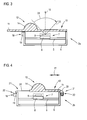
- Fig. 2 shows in more detail the structure of a radar sensor 2a according to the invention in a first embodiment.
- the core of the radar sensor 2a forms a printed circuit board 5, which is supported in a housing part 6 in the present case.
- a package 7 is arranged in CMOS technology in which a CMOS chip 8 and an antenna array 9 are realized.
- CMOS chip 8 a radar transceiver, a digital signal processing component and a control unit are realized. This means that the radar sensor 2a can be realized extremely compact and highly integrated.
- the housing part 6 open there is closed by a radome 11 for completing the housing.
- the Radom 11 is made of a high-frequency material, here polypropylene, and is thus permeable to radar radiation. It is solid and integrally formed here.
- the radome 11 here has a first radar optical section 12 and a second radar optical section 13.
- the radar optical section 12, which in the present case is arranged covering the antenna arrangement 9, has a hemispherical bulge 14, which thus creates a curved boundary surface, so that the effect of a lens on that of the antenna arrangement 9 emitted radar radiation is created. This has the consequence that an increased range of the radar radiation is given, however, the opening angle 15 of the detection area 16 is reduced.
- the radar optical section 13 is formed flat, which means that there is no additional lens effect at transition surfaces.
- a movement device 18, here with a linear motor 19, is provided which can move the radome 11 in the direction 17 in such a way in that either the radar optical section 12 covers the antenna arrangement 9 in a first mode position or the radar section 13 covers the antenna arrangement 9 in a second mode position, as shown in FIG Fig. 3 is shown.
- the radar optical section 13 which is flat, in a position covering the antenna assembly 9, so that the detection area 23 has a larger opening angle 24, but the range of the radar radiation is shorter.
- Fig. 4 shows a second embodiment of a radar sensor according to the invention 2b, in which for the sake of simplicity identical components are provided with the same reference numerals.
- the radome 11 is shorter than the length of the housing part 6 configured in the displacement direction and is held in the guide device again not shown in detail by two bands 20 as elements 21.
- the bands 20 are flexible and can be rolled up and down in respective rolling devices 22.
- This in turn is operated by a motor 19, with various concrete configurations exist to both modes positions to be able to take each other starting from the other, for example, the placement of a motor 19 on both sides, the provision of an elastic force on the side facing away from the motor 19, which tends to roll or training of the guide means such that the operation of a motor 19 one page is sufficient.
- the mode positions are determined by particular positions of the motor 19, it is of course also, possibly even additionally, possible to provide latching means, locking means and the like to define the mode position.
- latching means locking means and the like
- other realizations of the mobility of the radome 11 are conceivable, for example, a radome 11 with lateral, flexible sections, which are then guided laterally along the wall of the housing part 6 down and the like.
Landscapes
- Engineering & Computer Science (AREA)
- Radar, Positioning & Navigation (AREA)
- Remote Sensing (AREA)
- Physics & Mathematics (AREA)
- Computer Networks & Wireless Communication (AREA)
- General Physics & Mathematics (AREA)
- Computer Security & Cryptography (AREA)
- Electromagnetism (AREA)
- Radar Systems Or Details Thereof (AREA)
Abstract
Description
- Die Erfindung betrifft einen Radarsensor, insbesondere für ein Kraftfahrzeug, aufweisend einen auf einer Leiterplatte angeordneten, wenigstens einen Radar-Transceiver realisierenden CMOS-Chip, eine Antennenanordnung und ein Radom. Daneben betrifft die Erfindung ein Kraftfahrzeug mit einem solchen Radarsensor.
- Die Verwendung von Radarsensoren in Kraftfahrzeugen ist im Stand der Technik bereits weitgehend bekannt. Radarsensoren werden heutzutage meist als Umfeldsensoren für einen mittleren und größeren Distanzbereich eingesetzt, um andere Verkehrsteilnehmer oder größere Objekte in Distanz, Winkel und Relativgeschwindigkeit bestimmen zu können. Derartige Radardaten können in Umfeldmodelle eingehen oder auch unmittelbar Fahrzeugsystemen zur Verfügung gestellt werden. Nutzen aus Radardaten ziehen im bekannten Stand der Technik beispielsweise Längsführungssysteme, wie ACC, oder auch Sicherheitssysteme.
- Radarsensoren herkömmlicher Bauart weisen meist eine größere Ausdehnung auf und sind eher klobig, nachdem die Antennen sowie die unmittelbar an der Antenne benötigten Elektronikkomponenten, also das Radar-Frontend, in einem Gehäuse integriert sind. Hauptsächlich bilden die Elektronikkomponenten dabei den Radar-Transceiver, der eine Frequenzsteuerung (üblicherweise umfassend eine Phasenregelschleife - PLL), Mischeinrichtungen, einem Low Noise Amplifier (LNA) und dergleichen enthält, oft werden jedoch auch Steuermodule und digitale Signalverarbeitungskomponenten antennennah realisiert, beispielweise um bereits aufbereitete Sensordaten, beispielsweise Objektlisten, auf einen angeschlossenen Bus, beispielsweise einen CAN-Bus, geben zu können.
- Die Realisierung von Radarkomponenten auf Halbleiterbasis erwies sich lange Zeit als schwierig, da teure Spezialhalbleiter, insbesondere GaAs, benötigt wurden. Es wurden kleinere Radarsensoren vorgeschlagen, deren gesamtes Radar-Frontend auf einem einzigen Chip in SiGe-Technologie realisiert ist, ehe auch Lösungen in der CMOS-Technologie bekannt wurden. Solche Lösungen sind Ergebnis der Erweiterung der CMOS-Technologie auf Hochfrequenzanwendungen, was oft auch als RF-CMOS bezeichnet wird. Ein solcher CMOS-Radarchip ist äußerst kleinbauend realisiert und nutzt keine teuren Spezialhalbleiter, bietet also vor allem in der Herstellung deutliche Vorteile gegenüber anderen Halbleitertechnologien. Eine beispielhafte Realisierung eines 77 GHz-Radar-Transceivers als ein CMOS-Chip ist in dem Artikel von Jri Lee et al., "A Fully Integrated 77-GHz FMCW Radar Transceiver in 65-nm CMOS Technology", IEEE Journal of Solid State Circuits 45 (2010), S. 2746-2755, beschrieben.
- Nachdem zudem vorgeschlagen wurde, den Chip und die Antenne in einem gemeinsamen Package zu realisieren, ist ein äußerst kostengünstiger kleiner Radarsensor möglich, der Bauraumanforderungen deutlich besser erfüllen kann und aufgrund der kurzen Signalwege auch ein sehr niedriges Signal-Zu-Rausch-Verhältnis aufweist sowie für hohe Frequenzen und größere, variable Frequenzbandbreiten geeignet ist. Daher lassen sich derartige, kleinbauende Radarsensoren auch für Kurzreichweiten-Anwendungen, beispielsweise im Bereich von 30 cm bis 10 m, einsetzen.
- Es wurde auch bereits vorgeschlagen, einen solchen CMOS-Transceiver-Chip und/oder ein Package mit CMOS-Transceiver-Chip und Antenne auf einer gemeinsamen Leiterplatte mit einem digitalen Signalverarbeitungsprozessor (DSP-Prozessor) vorzusehen oder die Funktionen des Signalverarbeitungsprozessors ebenso in den CMOS-Transceiver-Chip zu integrieren. Eine ähnliche Integration ist für Steuerungsfunktionen möglich.
- Gezeigt hat sich, dass eine vom Aufwand her realisierbare Hochintegration, insbesondere also die Realisierung einer Antenne im Package mit einem Radarchip, der die sonstigen Komponenten des Radar-Frontends enthält, erst mit der Verfügbarkeit der CMOS-Technologie tatsächlich gegeben ist.
- Bei heute bekannten Radarsensoren spielt das Radom eine wichtige Rolle. Mit dem Wort Radom (kurz für "radar dome") wird üblicherweise die Abdeckung bezeichnet, die die Antennenanordnung des Radarsensors vor äußeren mechanischen und chemischen Einflüssen, beispielsweise vor Wind oder Regen, schützt. Das Radom ist dabei üblicherweise für Radarwellen durchlässig gestaltet, besteht mithin aus einem geeigneten Hochfrequenzmaterial (HF-Material). Durch die Form des Radoms können Detektionseigenschaften des Radarsensors beeinflusst werden, insbesondere der Öffnungswinkel des Erfassungsbereichs und die Reichweite des Radarsensors. Wird beispielsweise ein komplett flaches Radom verwendet, ergibt sich ein großer Öffnungswinkel, jedoch eine reduzierte Reichweite, da durch die zwei auftretenden Grenzflächen keine tatsächliche Beeinflussung des Radarsignals auftritt. Wird jedoch beispielsweise ein halbkugelförmig ausgewölbtes Radom verwendet, ergibt sich durch die gekrümmte äußere Grenzfläche ein Linseneffekt, der zwar den Öffnungswinkel reduziert, jedoch die Reichweite erhöht, da die Radarstrahlung auf einen kleineren Bereich fokussiert wird.
- Je nach der Anwendung, für die der Radarsensor geschaffen ist, wird er entweder mit einem flachen oder mit einem halbkugelförmigen Radom betrieben, das dem entsprechenden Radar-Frontend zugeordnet ist. Mithin wird der Fokus bezüglich eines Radarsensors entweder auf eine größere Reichweite oder auf einen größeren Öffnungswinkel gelegt. Häufig besteht jedoch der Wunsch, ausgehend von dem selben Ort Radardaten sowohl mit größerem Öffnungswinkel als auch mit größerer Reichweite zu erhalten. Dies ist bei den heute vorgegebenen Radoms nicht möglich.
- Der Erfindung liegt daher die Aufgabe zugrunde, einen Radarsensor anzugeben, der auf einfache Art und Weise unterschiedliche Detektionseigenschaften umsetzt.
- Zur Lösung dieser Aufgabe ist bei einem Radarsensor der eingangs genannten Art erfindungsgemäß vorgesehen, dass das insbesondere einstückige Radom wenigstens zwei unterschiedlich wirkende Radaroptikabschnitte aufweist und eine Bewegungseinrichtung zur Bewegung des Radoms in den einzelnen Radaroptikabschnitten zugeordnete Moduspositionen, in denen die Antennenanordnung durch den jeweiligen Radaroptikabschnitt ausstrahlt, vorgesehen ist.
- In den Moduspositionen überdeckt mithin der Radaroptikabschnitt die Antennenanordnung in Ausstrahlungsrichtung, so dass sich die durch den Radaroptikabschnitt definierten Ausstrahlungseigenschaften ergeben. Erfindungsgemäß wird also vorgeschlagen, die durch die CMOS-Technologie mögliche Hochintegration zu nutzen, insbesondere also die Existenz von Packages, die die Antennenanordnung und einen wenigstens den Radar-Transceiver realisierenden CMOS-Chip enthalten und auf einer Leiterplatte realisiert werden können, um einen kleinbauenden Radarsensor zu schaffen, der es ermöglicht, ihn ohne zu großen baulichen Aufwand und Kostenaufwand mit einem beweglichen Radom zu versehen. Das Radom weist Radaroptikabschnitte auf, die unterschiedliche Detektionseigenschaften für den Radarsensor definieren können, wobei bevorzugt zwei Radaroptikabschnitte vorgesehen sind, aber auch mehr als zwei Radaroptikabschnitte denkbar sind. Bevorzugt ist wenigstens der die Radaroptikabschnitte enthaltende Anteil des Radoms einstückig hergestellt, was bei der geringen benötigten Größe problemlos möglich ist.
- Mithin ist ein bewegbares, insbesondere verschiebbares, multifunktionales Radom als Teil des Gehäuses des Radarsensors vorhanden, so dass der Radarsensor, ohne dass an seinem sonstigen Betrieb etwas zu verändern wäre, mit unterschiedlichen Detektionseigenschaften, die durch die Radaroptikabschnitte definiert werden, betrieben werden kann. Je nachdem, in welcher Modusposition sich das Radom befindet, stehen für den Radarsensor mithin unterschiedliche Betriebsmodi zur Verfügung, um den Öffnungswinkel und die Reichweite des Sensors anzupassen, ohne dass das eigentliche Radar-Frontend bzw. die Antennenanordnung verändert werden muss. Beispielsweise kann das Radom einen Radaroptikabschnitt für die Erfassung im fernen Bereich und einen Radaroptikabschnitt für die Erfassung im nahen Bereich aufweisen, wobei auch andere Ausgestaltungen denkbar sind.
- Vorzugsweise ist das Radom bzw. wenigstens der die Radaroptikabschnitte realisierender Anteil dabei massiv, das bedeutet, es besteht durchgehend aus einem für Radarstrahlung durchlässigen Material, so dass die unterschiedlichen Detektionseigenschaften durch die Grenzflächen des Radoms realisiert werden. Grundsätzlich ist es für komplexere Radaroptikabschnitte jedoch auch denkbar, eine größere Anzahl von Grenzflächen durch eine hohle Ausbildung des Radoms zu realisieren, was jedoch hinsichtlich der Herstellung weniger bevorzugt ist.
- Eine konkrete Ausgestaltung der vorliegenden Erfindung sieht vor, dass das Radom wenigstens einen flachen Radaroptikabschnitt und wenigstens einen nach außen ausgewölbten, eine Linsenwirkung auf die Radarstrahlung ausübenden Radaroptikabschnitt aufweist. Dabei kann die Wölbung des gewölbten Radaroptikabschnitts insbesondere halbkugelförmig sein. Weist das Radom zwei Radaroptikabschnitte auf, sind mithin auch zwei Moduspositionen vorgesehen, kann das Radom in dem ersten Radaroptikabschnitt mit der Auswölbung einen Linseneffekt ausüben, mithin den Öffnungswinkel des Erfassungsbereichs reduzieren, jedoch die Reichweite steigern. Für die andere Modusposition kann ein Radaroptikabschnitt geschaffen werden, der flach ist und somit einen größeren Öffnungswinkel und eine reduzierte Reichweite realisiert. Die hier genannten Radaroptikabschnitte sind selbstverständlich beispielhaft zu verstehen, es sind grundsätzlich auch andere Formen, beispielsweise nach innen gewölbte Oberflächen, denkbar.
- Zweckmäßigerweise kann das Radom aus einem Hochfrequenzmaterial, insbesondere umfassend Polypropylen, bestehen. Wesentlich hierbei ist, dass das Hochfrequenzmaterial für Radarstrahlung möglichst durchlässig ist, mithin einen hohen Transmissionskoeffizienten aufweist. Als geeignetes Material hat sich Polypropylen bzw. eine Polypropylenmischung erwiesen, die auch für Stoßfänger von Kraftfahrzeugen häufig eingesetzt wird. In diesem Kontext ist es ferner zweckmäßig, wenn das Radom in einem Gussverfahren hergestellt ist. Das bevorzugt wenigstens im Anteil der Radaroptikabschnitte einstückige Radom, welches, wie dargestellt, bevorzugt ohnehin massiv ohne Hohlräume ist, kann durch Bereitstellung einer geeigneten Form in einem Gussverfahren auf einfache und kostengünstige Weise hergestellt werden.
- Eine besonders zweckmäßige Ausgestaltung der vorliegenden Erfindung sieht vor, dass die Antennenanordnung in einem Package mit dem CMOS-Chip realisiert ist. Dann ist ein äußerst kleinbauender Radarsensor gegeben, der insbesondere auch kurze Signalwege realisiert und mithin Störeffekte durch längere Signalwege vermeidet. Es ergibt sich hierdurch ein hervorragendes Signal-zu-Rausch-Verhältnis. Insbesondere jedoch können dann auch die Radaroptikabschnitte sowie das Radom an sich, welches zumindest im Anteil der Radaroptikabschnitte bewegbar ist, klein gehalten werden, was auch für die benötigte Mechanik der Bewegungseinrichtung gilt.
- Die Hochintegration lässt sich weiter dadurch verbessern, dass durch den CMOS-Chip auch eine digitale Signalverarbeitungskomponente und/oder eine Steuereinheit des Radarsensors realisiert ist. Eine in einem CMOS-Chip realisierte digitale Signalverarbeitungskomponente (DSP) kann für eine Vorauswertung der Daten sorgen, welche dann über die Steuereinheit beispielsweise bereits aufbereitet als Objektliste weitergegeben werden können.
- Zur konkreten Realisierung der Bewegungseinrichtung bzw. der Bewegbarkeit an sich sind verschiedene Ausgestaltungen denkbar. So sieht eine zweckmäßige Ausgestaltung vor, dass die Leiterplatte in einem in Ausstrahlungsrichtung offenen Gehäuseteil gehaltert ist, wobei das Radom in Ausstrahlungsrichtung auf dem Gehäuseteil verschiebbar und/oder rotierbar geführt ist, und/oder die Bewegungseinrichtung einen Motor, insbesondere einen Linearmotor, aufweist. Es kann mithin eine Führungseinrichtung vorgesehen sein, die das Radom oder zumindest den die Radaroptikabschnitte enthaltenen Anteil des Radoms entlang einer Verschieberichtung bzw. um eine Achse rotierbar oberhalb der Antennenanordnung in Ausstrahlungsrichtung führt. In einer einfachen Ausgestaltung kann, wenn genügend Bauraum um den Radarsensor zur Verfügung steht, eine lineare Verschiebbarkeit in einer Verschiebungsrichtung gegeben sein, wobei dann in jeder Modusposition das Radom das andere Gehäuseteil in Verschieberichtung etwa um die Verschiebelänge zwischen den Moduspositionen überragt. Diese Ausgestaltung wird bevorzugt bei einem einstückig hergestellten Radom eingesetzt und bietet den Vorteil, dass das Innere des durch das Radom abgeschlossenen Gehäuses immer vollständig nach außen abgeschlossen ist.
- Es sind jedoch auch Ausgestaltungen denkbar, in denen ein solches Überragen des Radoms über das restliche Gehäuse aus Bauraumgründen vermieden werden soll, wobei in einem solchen Fall beispielsweise vorgesehen sein kann, dass das Radom in Verschieberichtung kürzer als das Gehäuse ausgebildet ist oder einen kürzer als das Gehäuse ausgeführten starren Anteil aufweist, und seitlich durch wenigstens ein flexibles, geführtes Element gehaltert ist. Dabei kann das flexible Element auch ein flexibler Abschnitt des Radoms selbst sein, aber auch aus wenigstens einem getrennten Element, beispielsweise einem Band, realisiert sein. Aufgrund der Flexibilität des halternden Elements kann dieses beispielsweise senkrecht zur Verschieberichtung neben eine Gehäusewand des Gehäuseteils geführt werden, wo mithin ein zusätzlicher Stauraum zur Verfügung steht, der ein Überragen vermeidet. Denkbar ist es jedoch auch, insbesondere im Fall eines Bandes, das flexible, führende Element aufrollbar und/oder abrollbar auszugestalten, wobei dann beispielsweise die Bewegungseinrichtung als ein Motor direkt an einer Rolle zum Aufrollen des Elements, insbesondere eines Bandes, ansetzen kann. Durch eine geschickte Ausgestaltung der Führung ist es auch möglich, das Gehäuse dennoch insgesamt geschlossen zu halten, so dass der Radarsensor widerstandsfähig gegen äußere Einflüsse ist, auch wenn es die kleinbauende Ausgestaltung des Radarsensors häufig ermöglichen wird, ihn innerhalb von Hohlräumen, beispielsweise in einem Kraftfahrzeug, einzusetzen.
- Eine Weiterbildung in diesem Kontext sieht vor, dass bei einer elastischen Kraft auf das Element in einer Richtung die Bewegungseinrichtung zur Linearbewegung des Radom in Verschieberichtung ausgebildet ist. Das bedeutet, das Radom kann einseitig durch eine elastische Kraft vorbelastet gehalten sein, so dass die Ruhelage beispielsweise einer ersten Modusposition entspricht. Durch einen Aktor, insbesondere einen Motor, der Bewegungseinrichtung kann das Radom aus dieser Ruhelage in die wenigstens eine weitere Modusposition gegen die elastische Kraft gebracht werden. Beispielsweise kann hierfür ein Anschlag und/oder ein Rastmittel vorgesehen werden. Ist eine Verriegelungseinrichtung, beispielsweise ein Rastmittel, für die wenigstens eine weitere Modusposition gegeben, kann ein Rückführen in die der ersten Modusposition entsprechende Ruheposition durch Freigeben der Verriegelungseinrichtung an sich realisiert werden.
- Es ist jedoch auch denkbar, dass bei einem beidseitig durch aufrollbare Bänder gehaltenen Radom die Bewegungseinrichtung zum Aufrollen und/oder Abrollen wenigstens eines Bandes ausgebildet ist, so dass in dieser Ausgestaltung keine elastische Kraft benötigt wird, mithin keine längere Zeit vorliegende Vorbelastung des Radoms bzw. der halternden Elemente benötigt wird. Eine derartige Ausgestaltung lässt sich selbstverständlich auch realisieren, wenn das Radom flexible Abschnitte aufweist, die seitlich am Gehäuseteil nach unten geführt werden.
- Neben den hier konkret vorgebrachten Beispielen lassen sich selbstverständlich auch andere Möglichkeiten einsetzen, um die Bewegbarkeit der Radaroptikabschnitte und die entsprechende Einstellung von Moduspositionen zu erreichen. Allgemein können die Moduspositionen, falls notwendig, durch Rastmittel oder dergleichen markiert bzw. definiert werden, wobei auch eine Vordefinition bestimmter Stellungen des Motors der Bewegungseinrichtung ausreichend sein kann, um die Modusposition hinreichend genau zu definieren.
- Neben dem Radarsensor betrifft die vorliegende Erfindung auch ein Kraftfahrzeug, welches wenigstens einen erfindungsgemäßen Radarsensor aufweist. Sämtliche Ausführungen bezüglich des erfindungsgemäßen Radarsensors lassen sich analog auf das erfindungsgemäße Kraftfahrzeug übertragen, mit welchem mithin die bereits genannten Vorteile erhalten werden können. Der kleinbauend realisierte und unterschiedliche Detektionseigenschaften vom selben Ausgangspunkt ermöglichende Radarsensor lässt sich also besonders vorteilhaft in einem Kraftfahrzeug einsetzen, so dass beispielsweise mit einem einzigen, kleinbauenden Radarsensor Daten aus einem Fernbereich und einem Nahbereich erhalten werden können.
- In einer Weiterbildung des Kraftfahrzeugs kann vorgesehen sein, dass es wenigstens ein Steuergerät eines Fahrzeugsystems aufweist, welches zur Ansteuerung der Bewegungseinrichtung zur Einstellung einer Modusposition des Radoms in Abhängigkeit der für eine Funktion benötigten Radardaten des Radarsensors ausgebildet ist. Die Radardaten des Radarsensors werden üblicherweise in einem Steuergerät, das wenigstens einem Fahrzeugsystem zugeordnet ist, verarbeitet, beispielsweise in einem Steuergerät für längsführende Fahrerassistenzsysteme oder dergleichen. In Funktionen, die durch ein derartiges Steuergerät realisiert werden, kann es dabei vorkommen, dass unterschiedliche Radardaten angefordert werden, beispielsweise zu einem ersten Zeitpunkt Radardaten aus einem Nahbereich mit großem Öffnungswinkel, zu einem späteren Zeitpunkt Radardaten aus einem Fernbereich mit einem schmaleren Öffnungswinkel. Hieraus ergibt sich aber, dass eine entsprechende Anforderung im Steuergerät erstellt werden kann und genutzt werden kann, um die Bewegungseinrichtung, gegebenenfalls auch indirekt über eine Steuereinheit des Radarsensors, anzusteuern, so dass das Radom die entsprechende Modusposition einnimmt und der Radarsensor im Folgenden die tatsächlich benötigten Radardaten liefert.
- Weitere Vorteile und Einzelheiten der vorliegenden Erfindung ergeben sich aus den im Folgenden beschriebenen Ausführungsbeispielen sowie anhand der Zeichnung. Dabei zeigen:
- Fig. 1
- eine Prinzipskizze eines erfindungsgemäßen Kraftfahrzeugs,
- Fig. 2
- einen erfindungsgemäßen Radarsensor mit einem Radom in einer ersten Modusposition,
- Fig. 3
- den erfindungsgemäßen Radarsensor der
Fig. 2 mit dem Radom in einer zweiten Modusposition, und - Fig. 4
- eine alternative Ausführungsform eines erfindungsgemäßen Radarsensors.
-
Fig. 1 zeigt eine Prinzipskizze eines erfindungsgemäßen Kraftfahrzeugs 1. Das Kraftfahrzeug 1 weist vorliegend vier erfindungsgemäße Radarsensoren 2 auf, die auf den Bereich vor und hinter dem Kraftfahrzeug 1 gerichtet sind. Die Radardaten der Radarsensoren werden an wenigstens ein Steuergerät 3 des Kraftfahrzeugs 1 weitergeleitet, das wenigstens einem Fahrzeugsystem 4 zugeordnet ist. Das Steuergerät 3 kann abhängig von den Anforderungen einer durch es ausgeführten Funktion bestimmte Detektionseigenschaften von den Radarsensoren 2 anfordern, die wie im Folgenden dargestellt realisiert werden können. -
Fig. 2 zeigt genauer den Aufbau eines erfindungsgemäßen Radarsensors 2a in einer ersten Ausführungsform. Kernstück des Radarsensors 2a bildet eine Leiterplatte 5, die vorliegend in einem Gehäuseteil 6 gehaltert ist. Auf der Leiterplatte 5 ist ein Package 7 in CMOS-Technologie angeordnet, in dem ein CMOS-Chip 8 und eine Antennenanordnung 9 realisiert sind. In dem CMOS-Chip 8 sind ein Radar-Transceiver, eine digitale Signalverarbeitungskomponente und eine Steuereinheit realisiert. Das bedeutet, der Radarsensor 2a kann äußerst kleinbauend und hochintegriert realisiert werden. - In Ausstrahlungsrichtung 10 ist das dorthin offene Gehäuseteil 6 durch ein Radom 11 zur Vervollständigung des Gehäuses abgeschlossen. Das Radom 11 besteht aus einem Hochfrequenz-Material, hier Polypropylen, und ist somit für Radarstrahlung durchlässig. Es ist hier massiv und einstückig ausgebildet. Das Radom 11 weist vorliegend einen ersten Radaroptikabschnitt 12 und einen zweiten Radaroptikabschnitt 13 auf. Der Radaroptikabschnitt 12, der vorliegend die Antennenanordnung 9 überdeckend angeordnet ist, weist eine halbkugelförmige Auswölbung 14 auf, die mithin eine gebogene Grenzfläche schafft, so dass die Wirkung einer Linse auf die von der Antennenanordnung 9 ausgesandte Radarstrahlung entsteht. Dies hat hier die Folge, dass eine erhöhte Reichweite der Radarstrahlung gegeben ist, jedoch der Öffnungswinkel 15 des Erfassungsbereichs 16 reduziert ist.
- Der Radaroptikabschnitt 13 ist flach ausgebildet, das bedeutet, hier ist keine zusätzliche Linsenwirkung an Übergangsflächen gegeben.
- Über eine hier nicht näher gezeigte Führungseinrichtung ist das Radom 11 auf dem Gehäuseteil 6 in der Verschieberichtung 17 verschiebbar, wobei zur Automatisierung dieses Vorgangs eine Bewegungseinrichtung 18, hier mit einem Linearmotor 19, vorgesehen ist, der das Radom 11 in der Verschieberichtung 17 derart verschieben kann, dass entweder der Radaroptikabschnitt 12 in einer ersten Modusposition die Antennenanordnung 9 überdeckt oder der Radarabschnitt 13 in einer zweiten Modusposition die Antennenanordnung 9 überdeckt, wie dies in
Fig. 3 gezeigt ist. Dort befindet sich nun der Radaroptikabschnitt 13, der flach ist, in einer die Antennenanordnung 9 überdeckenden Position, so dass der Erfassungsbereich 23 einen größeren Öffnungswinkel 24 aufweist, jedoch die Reichweite der Radarstrahlung kürzer ist. - So lässt sich mithin durch einfaches Verschieben des Radoms 11 eine Mehrzahl von Detektionseigenschaften des Radarsensors 2a erreichen, ohne dass an dem Radar-Frontend, das durch das Package 7 gebildet wird, eine Veränderung notwendig wäre.
-
Fig. 4 zeigt schließlich eine zweite Ausführungsform eines erfindungsgemäßen Radarsensors 2b, bei dem der Einfachheit halber gleiche Komponenten mit den gleichen Bezugszeichen versehen sind. Im hier dargestellten Beispiel ist das Radom 11 kürzer als die Länge des Gehäuseteils 6 in Verschieberichtung ausgestaltet und wird in der wiederum nicht näher gezeigten Führungseinrichtung durch zwei Bänder 20 als Elemente 21 gehalten. Die Bänder 20 sind flexibel und können in entsprechenden Rollvorrichtungen 22 aufund abgerollt werden. Dies geschieht wiederum betrieben durch einen Motor 19, wobei verschiedene konkrete Ausgestaltungen existieren, um beide Moduspositionen jeweils ausgehend von der anderen einnehmen zu können, beispielsweise die Platzierung eines Motors 19 zu beiden Seiten, das Vorsehen einer elastischen Kraft auf der dem Motor 19 abgewandten Seite, die zum Aufrollen tendiert oder eine Ausbildung der Führungseinrichtungen derart, dass der Betrieb eines Motors 19 auf einer Seite ausreichend ist. - Während in den hier dargelegten Ausführungsbeispielen die Moduspositionen durch bestimmte Stellungen des Motors 19 bestimmt werden, ist es selbstverständlich auch, gegebenenfalls sogar zusätzlich, möglich, Rastmittel, Verriegelungseinrichtungen und dergleichen vorzusehen, um die Modusposition zu definieren. Auch sind selbstverständlich andere Realisierungen der Bewegbarkeit des Radoms 11 denkbar, beispielsweise ein Radom 11 mit seitlichen, flexiblen Abschnitten, die dann seitlich entlang der Wand des Gehäuseteils 6 nach unten geführt werden und dergleichen.
Claims (9)
- Radarsensor (2, 2a, 2b), aufweisend wenigstens einen Radar-Transceiver, eine Antennenanordnung (9), ein Radom (11) und eine Bewegungseinrichtung (18),
dadurch gekennzeichnet,
dass das insbesondere einstückige Radom (11) wenigstens zwei unterschiedlich wirkende Radaroptikabschnitte (12, 13) aufweist und die Bewegungseinrichtung (18) zur Bewegung des Radoms (11) in den einzelnen Radaroptikabschnitten (12, 13) zugeordnete Moduspositionen, in denen die Antennenanordnung (9) durch den jeweiligen Radaroptikabschnitt (12, 13) ausstrahlt, vorgesehen ist, wobei der wenigstens eine Radar-Transceiver als ein auf einer Leiterplatte (5) angeordneter CMOS-Chip (8) und die Antennenanordnung (9) in einem Package (7) mit dem CMOS-Chip (8) realisiert ist. - Radarsensor nach Anspruch 1,
dadurch gekennzeichnet,
dass durch den CMOS-Chip (8) auch eine digitale Signalverarbeitungskomponente und/oder eine Steuereinheit des Radarsensors (2, 2a, 2b) realisiert ist. - Radarsensor nach Anspruch 1 oder 2,
dadurch gekennzeichnet,
dass das Radom (11) wenigstens einen flachen Radaroptikabschnitt (13) und wenigstens einen nach außen ausgewölbten, eine Linsenwirkung auf die Radarstrahlung ausübenden Radaroptikabschnitt (12) aufweist. - Radarsensor nach einem der vorangehenden Ansprüche,
dadurch gekennzeichnet,
dass das Radom (11) aus einem Hochfrequenzmaterial, insbesondere umfassend Polypropylen, besteht und/oder in einem Gussverfahren hergestellt ist. - Radarsensor nach einem der vorangehenden Ansprüche,
dadurch gekennzeichnet,
dass die Leiterplatte (5) in einem in Ausstrahlungsrichtung (10) offenen Gehäuseteil (6) gehaltert ist, wobei das Radom (11) in Ausstrahlungsrichtung auf dem Gehäuseteil (6) verschiebbar und/oder rotierbar geführt ist, und/oder die Bewegungseinrichtung (18) einen Motor (19), insbesondere einen Linearmotor, aufweist. - Radarsensor nach Anspruch 5,
dadurch gekennzeichnet,
dass das Radom (11) in Verschieberichtung (17) kürzer als das Gehäuseteil (6) ausgebildet ist oder einen kürzer als das Gehäuseteil (6) ausgeführten starren Anteil aufweist, und seitlich durch wenigstens ein flexibles, geführtes Element (21) gehaltert ist. - Radarsensor nach Anspruch 6,
dadurch gekennzeichnet,
dass bei einer elastischen Kraft auf das Element (21) in einer Richtung die Bewegungseinrichtung (18) zum Linearbewegung des Radoms (11) in Verschieberichtung (17) ausgebildet ist und/oder bei einem beidseitig durch aufrollbare Bänder (20) gehaltenen Radom (11) die Bewegungseinrichtung (18) zum Aufrollen und/oder Abrollen wenigstens eines Bandes (20) ausgebildet ist. - Kraftfahrzeug (1), umfassend wenigstens einen Radarsensor (2, 2a, 2b) nach einem der vorangehenden Ansprüche.
- Kraftfahrzeug nach Anspruch 8,
dadurch gekennzeichnet,
dass es wenigstens ein Steuergerät (3) eines Fahrzeugsystems (4) aufweist, welches zur Ansteuerung der Bewegungseinrichtung (18) zur Einstellung einer Modusposition des Radoms (11) in Abhängigkeit der für eine Funktion benötigten Radardaten des Radarsensors (2, 2a, 2b) ausgebildet ist.
Applications Claiming Priority (1)
| Application Number | Priority Date | Filing Date | Title |
|---|---|---|---|
| DE102014013003.7A DE102014013003A1 (de) | 2014-08-29 | 2014-08-29 | Radarsensor, insbesondere für ein Kraftfahrzeug, und Kraftfahrzeug |
Publications (2)
| Publication Number | Publication Date |
|---|---|
| EP2990823A1 true EP2990823A1 (de) | 2016-03-02 |
| EP2990823B1 EP2990823B1 (de) | 2019-12-18 |
Family
ID=53298077
Family Applications (1)
| Application Number | Title | Priority Date | Filing Date |
|---|---|---|---|
| EP15001561.8A Active EP2990823B1 (de) | 2014-08-29 | 2015-05-22 | Radarsensor, insbesondere für ein kraftfahrzeug, und kraftfahrzeug |
Country Status (2)
| Country | Link |
|---|---|
| EP (1) | EP2990823B1 (de) |
| DE (1) | DE102014013003A1 (de) |
Cited By (3)
| Publication number | Priority date | Publication date | Assignee | Title |
|---|---|---|---|---|
| WO2022084117A1 (de) * | 2020-10-22 | 2022-04-28 | Valeo Schalter Und Sensoren Gmbh | Radarsensor mit einem radarchip, einer antennenstruktur und einem bauteilträger |
| EP4043841A1 (de) * | 2021-02-12 | 2022-08-17 | Rosemount Tank Radar AB | Radarfüllstandsmessgerät mit elastischem system |
| EP4415172A4 (de) * | 2021-10-07 | 2025-10-15 | Lg Innotek Co Ltd | Radarvorrichtung und ansteuerungsverfahren dafür |
Families Citing this family (1)
| Publication number | Priority date | Publication date | Assignee | Title |
|---|---|---|---|---|
| DE102014014294B4 (de) * | 2014-09-25 | 2021-05-12 | Audi Ag | Stoßfänger für ein Kraftfahrzeug und Kraftfahrzeug |
Citations (6)
| Publication number | Priority date | Publication date | Assignee | Title |
|---|---|---|---|---|
| DE10059891A1 (de) * | 2000-12-01 | 2002-06-13 | Continental Teves Ag & Co Ohg | Kraftfahrzeugabstandssensor |
| EP1220353A2 (de) * | 2000-12-29 | 2002-07-03 | Robert Bosch Gmbh | Vorrichtung zum räumlichen Schwenken eines Radarstrahls |
| DE69806276T2 (de) * | 1997-01-07 | 2002-11-07 | Murata Mfg. Co., Ltd. | Antenne und Übertragungs- und Empfangsvorrichtung mit einer derartigen Antenne |
| DE10235337A1 (de) * | 2002-08-02 | 2004-02-12 | Robert Bosch Gmbh | Abdeckvorrichtung für ein Kraftfahrzeugradar |
| JP2006105866A (ja) * | 2004-10-07 | 2006-04-20 | Matsushita Electric Ind Co Ltd | レーダ装置 |
| DE102007027975A1 (de) * | 2007-06-19 | 2008-12-24 | Robert Bosch Gmbh | Sensorvorrichtung für ein Kraftfahrzeug |
Family Cites Families (1)
| Publication number | Priority date | Publication date | Assignee | Title |
|---|---|---|---|---|
| US7830301B2 (en) * | 2008-04-04 | 2010-11-09 | Toyota Motor Engineering & Manufacturing North America, Inc. | Dual-band antenna array and RF front-end for automotive radars |
-
2014
- 2014-08-29 DE DE102014013003.7A patent/DE102014013003A1/de not_active Ceased
-
2015
- 2015-05-22 EP EP15001561.8A patent/EP2990823B1/de active Active
Patent Citations (6)
| Publication number | Priority date | Publication date | Assignee | Title |
|---|---|---|---|---|
| DE69806276T2 (de) * | 1997-01-07 | 2002-11-07 | Murata Mfg. Co., Ltd. | Antenne und Übertragungs- und Empfangsvorrichtung mit einer derartigen Antenne |
| DE10059891A1 (de) * | 2000-12-01 | 2002-06-13 | Continental Teves Ag & Co Ohg | Kraftfahrzeugabstandssensor |
| EP1220353A2 (de) * | 2000-12-29 | 2002-07-03 | Robert Bosch Gmbh | Vorrichtung zum räumlichen Schwenken eines Radarstrahls |
| DE10235337A1 (de) * | 2002-08-02 | 2004-02-12 | Robert Bosch Gmbh | Abdeckvorrichtung für ein Kraftfahrzeugradar |
| JP2006105866A (ja) * | 2004-10-07 | 2006-04-20 | Matsushita Electric Ind Co Ltd | レーダ装置 |
| DE102007027975A1 (de) * | 2007-06-19 | 2008-12-24 | Robert Bosch Gmbh | Sensorvorrichtung für ein Kraftfahrzeug |
Non-Patent Citations (2)
| Title |
|---|
| JRI LEE ET AL.: "A Fully Integrated 77-GHz FMCW Radar Transceiver in 65-nm CMOS Technology", IEEE JOURNAL OF SOLID STATE CIRCUITS, vol. 45, 2010, pages 2746 - 2755 |
| JRI LEE ET AL: "A Fully-Integrated 77-GHz FMCW Radar Transceiver in 65-nm CMOS Technology", IEEE JOURNAL OF SOLID-STATE CIRCUITS, vol. 45, no. 12, 1 December 2010 (2010-12-01), pages 2746 - 2756, XP055088008, ISSN: 0018-9200, DOI: 10.1109/JSSC.2010.2075250 * |
Cited By (6)
| Publication number | Priority date | Publication date | Assignee | Title |
|---|---|---|---|---|
| WO2022084117A1 (de) * | 2020-10-22 | 2022-04-28 | Valeo Schalter Und Sensoren Gmbh | Radarsensor mit einem radarchip, einer antennenstruktur und einem bauteilträger |
| EP4043841A1 (de) * | 2021-02-12 | 2022-08-17 | Rosemount Tank Radar AB | Radarfüllstandsmessgerät mit elastischem system |
| EP4043842A1 (de) * | 2021-02-12 | 2022-08-17 | Rosemount Tank Radar AB | Radarfüllstandsmessgerät mit elastischem system |
| US12276537B2 (en) | 2021-02-12 | 2025-04-15 | Rosemount Tank Radar Ab | Radar level gauge with elastic system |
| EP4415172A4 (de) * | 2021-10-07 | 2025-10-15 | Lg Innotek Co Ltd | Radarvorrichtung und ansteuerungsverfahren dafür |
| US12529788B2 (en) | 2021-10-07 | 2026-01-20 | Lg Innotek Co., Ltd. | Radar device and driving method therefor |
Also Published As
| Publication number | Publication date |
|---|---|
| DE102014013003A1 (de) | 2016-03-03 |
| EP2990823B1 (de) | 2019-12-18 |
Similar Documents
| Publication | Publication Date | Title |
|---|---|---|
| EP3198300B1 (de) | Verfahren zum betrieb einer mehrzahl von radarsensoren in einem kraftfahrzeug und kraftfahrzeug | |
| EP2966725A1 (de) | Radom für eine radarsensoreinrichtung mit wenigstens zwei radarsensoren und radarsensoreinrichtung | |
| EP2990823B1 (de) | Radarsensor, insbesondere für ein kraftfahrzeug, und kraftfahrzeug | |
| EP3701280B1 (de) | Radarsensor mit mehreren hauptstrahlrichtungen | |
| DE112021002988T5 (de) | Hohlleiter-schlitzantenne | |
| WO2017191201A1 (de) | Kraftfahrzeug mit wenigstens zwei radarsensoren | |
| DE2244724A1 (de) | Steuereinrichtung fuer eine antennenzeile zum erzeugen elektronisch schwenkbarer strahlungsdiagramme | |
| DE102017200689A1 (de) | Fahrzeug | |
| DE102014009861B4 (de) | Radarsensorvorrichtung mit wenigstens zwei Radarsensoren und Kraftfahrzeug | |
| EP3255727A1 (de) | Antennen-dachmodul für ein kraftfahrzeug und kraftfahrzeug | |
| DE102018118863A1 (de) | Radarvorrichtung und Verfahren zum Erzeugen unterschiedlicher Richtcharakteristika | |
| DE102016220084A1 (de) | Kraftfahrzeug mit wenigstens einer Tür und einem Radarsensor, Verfahren zur Steuerung einer Antriebseinrichtung für eine Tür eines Kraftfahrzeugs | |
| DE102014009869A1 (de) | Verfahren zum Betrieb eines Radarsensors in einem Kraftfahrzeug und Kraftfahrzeug | |
| DE102017206944A1 (de) | Verfahren zum Betrieb eines Radarsensors in einem Kraftfahrzeug, Radarsensor und Kraftfahrzeug | |
| DE102014222837A1 (de) | Radarsystem | |
| DE102017216567A1 (de) | Verfahrung zur Ermittlung einer Umgebungskarte in einem Kraftfahrzeug und Kraftfahrzeug | |
| DE102014014294B4 (de) | Stoßfänger für ein Kraftfahrzeug und Kraftfahrzeug | |
| DE102017214020B4 (de) | Kraftfahrzeug mit mehreren Radarsensoren zur Umfelderfassung | |
| DE102021118076A1 (de) | Radar-System sowie entsprechendes Verfahren | |
| DE102017212722A1 (de) | Radarsensor mit mehreren Hauptstrahlrichtungen | |
| EP3516416B1 (de) | Radaranordnung für ein kraftfahrzeug und kraftfahrzeug | |
| DE102020121980B3 (de) | Kraftfahrzeug mit wenigstens einem Radarsensor und Verfahren zum Betrieb eines Kraftfahrzeugs | |
| DE102016219512A1 (de) | Kraftfahrzeug mit einer öffenbaren Motorhaube und Verfahren zum Betrieb eines Kollisionsschutzsystems für eine Motorhaube | |
| EP3136124B1 (de) | Verfahren zum betrieb von radarsensoren in einem kraftfahrzeug und kraftfahrzeug | |
| DE102016216248B3 (de) | Kraftfahrzeug mit einer Scheibenwischeinrichtung und einem Radarsensor |
Legal Events
| Date | Code | Title | Description |
|---|---|---|---|
| PUAI | Public reference made under article 153(3) epc to a published international application that has entered the european phase |
Free format text: ORIGINAL CODE: 0009012 |
|
| AK | Designated contracting states |
Kind code of ref document: A1 Designated state(s): AL AT BE BG CH CY CZ DE DK EE ES FI FR GB GR HR HU IE IS IT LI LT LU LV MC MK MT NL NO PL PT RO RS SE SI SK SM TR |
|
| AX | Request for extension of the european patent |
Extension state: BA ME |
|
| 17P | Request for examination filed |
Effective date: 20160902 |
|
| RBV | Designated contracting states (corrected) |
Designated state(s): AL AT BE BG CH CY CZ DE DK EE ES FI FR GB GR HR HU IE IS IT LI LT LU LV MC MK MT NL NO PL PT RO RS SE SI SK SM TR |
|
| STAA | Information on the status of an ep patent application or granted ep patent |
Free format text: STATUS: EXAMINATION IS IN PROGRESS |
|
| 17Q | First examination report despatched |
Effective date: 20180403 |
|
| GRAP | Despatch of communication of intention to grant a patent |
Free format text: ORIGINAL CODE: EPIDOSNIGR1 |
|
| STAA | Information on the status of an ep patent application or granted ep patent |
Free format text: STATUS: GRANT OF PATENT IS INTENDED |
|
| INTG | Intention to grant announced |
Effective date: 20190930 |
|
| GRAS | Grant fee paid |
Free format text: ORIGINAL CODE: EPIDOSNIGR3 |
|
| GRAA | (expected) grant |
Free format text: ORIGINAL CODE: 0009210 |
|
| STAA | Information on the status of an ep patent application or granted ep patent |
Free format text: STATUS: THE PATENT HAS BEEN GRANTED |
|
| AK | Designated contracting states |
Kind code of ref document: B1 Designated state(s): AL AT BE BG CH CY CZ DE DK EE ES FI FR GB GR HR HU IE IS IT LI LT LU LV MC MK MT NL NO PL PT RO RS SE SI SK SM TR |
|
| REG | Reference to a national code |
Ref country code: CH Ref legal event code: EP |
|
| REG | Reference to a national code |
Ref country code: DE Ref legal event code: R096 Ref document number: 502015011234 Country of ref document: DE |
|
| REG | Reference to a national code |
Ref country code: IE Ref legal event code: FG4D Free format text: LANGUAGE OF EP DOCUMENT: GERMAN |
|
| REG | Reference to a national code |
Ref country code: AT Ref legal event code: REF Ref document number: 1215238 Country of ref document: AT Kind code of ref document: T Effective date: 20200115 |
|
| REG | Reference to a national code |
Ref country code: NL Ref legal event code: MP Effective date: 20191218 |
|
| PG25 | Lapsed in a contracting state [announced via postgrant information from national office to epo] |
Ref country code: SE Free format text: LAPSE BECAUSE OF FAILURE TO SUBMIT A TRANSLATION OF THE DESCRIPTION OR TO PAY THE FEE WITHIN THE PRESCRIBED TIME-LIMIT Effective date: 20191218 Ref country code: LV Free format text: LAPSE BECAUSE OF FAILURE TO SUBMIT A TRANSLATION OF THE DESCRIPTION OR TO PAY THE FEE WITHIN THE PRESCRIBED TIME-LIMIT Effective date: 20191218 Ref country code: FI Free format text: LAPSE BECAUSE OF FAILURE TO SUBMIT A TRANSLATION OF THE DESCRIPTION OR TO PAY THE FEE WITHIN THE PRESCRIBED TIME-LIMIT Effective date: 20191218 Ref country code: BG Free format text: LAPSE BECAUSE OF FAILURE TO SUBMIT A TRANSLATION OF THE DESCRIPTION OR TO PAY THE FEE WITHIN THE PRESCRIBED TIME-LIMIT Effective date: 20200318 Ref country code: LT Free format text: LAPSE BECAUSE OF FAILURE TO SUBMIT A TRANSLATION OF THE DESCRIPTION OR TO PAY THE FEE WITHIN THE PRESCRIBED TIME-LIMIT Effective date: 20191218 Ref country code: GR Free format text: LAPSE BECAUSE OF FAILURE TO SUBMIT A TRANSLATION OF THE DESCRIPTION OR TO PAY THE FEE WITHIN THE PRESCRIBED TIME-LIMIT Effective date: 20200319 Ref country code: NO Free format text: LAPSE BECAUSE OF FAILURE TO SUBMIT A TRANSLATION OF THE DESCRIPTION OR TO PAY THE FEE WITHIN THE PRESCRIBED TIME-LIMIT Effective date: 20200318 |
|
| REG | Reference to a national code |
Ref country code: LT Ref legal event code: MG4D |
|
| PG25 | Lapsed in a contracting state [announced via postgrant information from national office to epo] |
Ref country code: HR Free format text: LAPSE BECAUSE OF FAILURE TO SUBMIT A TRANSLATION OF THE DESCRIPTION OR TO PAY THE FEE WITHIN THE PRESCRIBED TIME-LIMIT Effective date: 20191218 Ref country code: RS Free format text: LAPSE BECAUSE OF FAILURE TO SUBMIT A TRANSLATION OF THE DESCRIPTION OR TO PAY THE FEE WITHIN THE PRESCRIBED TIME-LIMIT Effective date: 20191218 |
|
| PG25 | Lapsed in a contracting state [announced via postgrant information from national office to epo] |
Ref country code: AL Free format text: LAPSE BECAUSE OF FAILURE TO SUBMIT A TRANSLATION OF THE DESCRIPTION OR TO PAY THE FEE WITHIN THE PRESCRIBED TIME-LIMIT Effective date: 20191218 |
|
| PG25 | Lapsed in a contracting state [announced via postgrant information from national office to epo] |
Ref country code: RO Free format text: LAPSE BECAUSE OF FAILURE TO SUBMIT A TRANSLATION OF THE DESCRIPTION OR TO PAY THE FEE WITHIN THE PRESCRIBED TIME-LIMIT Effective date: 20191218 Ref country code: PT Free format text: LAPSE BECAUSE OF FAILURE TO SUBMIT A TRANSLATION OF THE DESCRIPTION OR TO PAY THE FEE WITHIN THE PRESCRIBED TIME-LIMIT Effective date: 20200513 Ref country code: CZ Free format text: LAPSE BECAUSE OF FAILURE TO SUBMIT A TRANSLATION OF THE DESCRIPTION OR TO PAY THE FEE WITHIN THE PRESCRIBED TIME-LIMIT Effective date: 20191218 Ref country code: NL Free format text: LAPSE BECAUSE OF FAILURE TO SUBMIT A TRANSLATION OF THE DESCRIPTION OR TO PAY THE FEE WITHIN THE PRESCRIBED TIME-LIMIT Effective date: 20191218 Ref country code: EE Free format text: LAPSE BECAUSE OF FAILURE TO SUBMIT A TRANSLATION OF THE DESCRIPTION OR TO PAY THE FEE WITHIN THE PRESCRIBED TIME-LIMIT Effective date: 20191218 |
|
| PG25 | Lapsed in a contracting state [announced via postgrant information from national office to epo] |
Ref country code: IS Free format text: LAPSE BECAUSE OF FAILURE TO SUBMIT A TRANSLATION OF THE DESCRIPTION OR TO PAY THE FEE WITHIN THE PRESCRIBED TIME-LIMIT Effective date: 20200418 Ref country code: SK Free format text: LAPSE BECAUSE OF FAILURE TO SUBMIT A TRANSLATION OF THE DESCRIPTION OR TO PAY THE FEE WITHIN THE PRESCRIBED TIME-LIMIT Effective date: 20191218 Ref country code: SM Free format text: LAPSE BECAUSE OF FAILURE TO SUBMIT A TRANSLATION OF THE DESCRIPTION OR TO PAY THE FEE WITHIN THE PRESCRIBED TIME-LIMIT Effective date: 20191218 |
|
| REG | Reference to a national code |
Ref country code: DE Ref legal event code: R097 Ref document number: 502015011234 Country of ref document: DE |
|
| PLBE | No opposition filed within time limit |
Free format text: ORIGINAL CODE: 0009261 |
|
| STAA | Information on the status of an ep patent application or granted ep patent |
Free format text: STATUS: NO OPPOSITION FILED WITHIN TIME LIMIT |
|
| PG25 | Lapsed in a contracting state [announced via postgrant information from national office to epo] |
Ref country code: ES Free format text: LAPSE BECAUSE OF FAILURE TO SUBMIT A TRANSLATION OF THE DESCRIPTION OR TO PAY THE FEE WITHIN THE PRESCRIBED TIME-LIMIT Effective date: 20191218 Ref country code: DK Free format text: LAPSE BECAUSE OF FAILURE TO SUBMIT A TRANSLATION OF THE DESCRIPTION OR TO PAY THE FEE WITHIN THE PRESCRIBED TIME-LIMIT Effective date: 20191218 |
|
| 26N | No opposition filed |
Effective date: 20200921 |
|
| PG25 | Lapsed in a contracting state [announced via postgrant information from national office to epo] |
Ref country code: SI Free format text: LAPSE BECAUSE OF FAILURE TO SUBMIT A TRANSLATION OF THE DESCRIPTION OR TO PAY THE FEE WITHIN THE PRESCRIBED TIME-LIMIT Effective date: 20191218 |
|
| PG25 | Lapsed in a contracting state [announced via postgrant information from national office to epo] |
Ref country code: IT Free format text: LAPSE BECAUSE OF FAILURE TO SUBMIT A TRANSLATION OF THE DESCRIPTION OR TO PAY THE FEE WITHIN THE PRESCRIBED TIME-LIMIT Effective date: 20191218 Ref country code: MC Free format text: LAPSE BECAUSE OF FAILURE TO SUBMIT A TRANSLATION OF THE DESCRIPTION OR TO PAY THE FEE WITHIN THE PRESCRIBED TIME-LIMIT Effective date: 20191218 Ref country code: CH Free format text: LAPSE BECAUSE OF NON-PAYMENT OF DUE FEES Effective date: 20200531 Ref country code: LI Free format text: LAPSE BECAUSE OF NON-PAYMENT OF DUE FEES Effective date: 20200531 |
|
| PG25 | Lapsed in a contracting state [announced via postgrant information from national office to epo] |
Ref country code: PL Free format text: LAPSE BECAUSE OF FAILURE TO SUBMIT A TRANSLATION OF THE DESCRIPTION OR TO PAY THE FEE WITHIN THE PRESCRIBED TIME-LIMIT Effective date: 20191218 |
|
| REG | Reference to a national code |
Ref country code: BE Ref legal event code: MM Effective date: 20200531 |
|
| PG25 | Lapsed in a contracting state [announced via postgrant information from national office to epo] |
Ref country code: LU Free format text: LAPSE BECAUSE OF NON-PAYMENT OF DUE FEES Effective date: 20200522 |
|
| PG25 | Lapsed in a contracting state [announced via postgrant information from national office to epo] |
Ref country code: IE Free format text: LAPSE BECAUSE OF NON-PAYMENT OF DUE FEES Effective date: 20200522 |
|
| PG25 | Lapsed in a contracting state [announced via postgrant information from national office to epo] |
Ref country code: BE Free format text: LAPSE BECAUSE OF NON-PAYMENT OF DUE FEES Effective date: 20200531 |
|
| REG | Reference to a national code |
Ref country code: AT Ref legal event code: MM01 Ref document number: 1215238 Country of ref document: AT Kind code of ref document: T Effective date: 20200522 |
|
| PG25 | Lapsed in a contracting state [announced via postgrant information from national office to epo] |
Ref country code: AT Free format text: LAPSE BECAUSE OF NON-PAYMENT OF DUE FEES Effective date: 20200522 |
|
| PG25 | Lapsed in a contracting state [announced via postgrant information from national office to epo] |
Ref country code: TR Free format text: LAPSE BECAUSE OF FAILURE TO SUBMIT A TRANSLATION OF THE DESCRIPTION OR TO PAY THE FEE WITHIN THE PRESCRIBED TIME-LIMIT Effective date: 20191218 Ref country code: MT Free format text: LAPSE BECAUSE OF FAILURE TO SUBMIT A TRANSLATION OF THE DESCRIPTION OR TO PAY THE FEE WITHIN THE PRESCRIBED TIME-LIMIT Effective date: 20191218 Ref country code: CY Free format text: LAPSE BECAUSE OF FAILURE TO SUBMIT A TRANSLATION OF THE DESCRIPTION OR TO PAY THE FEE WITHIN THE PRESCRIBED TIME-LIMIT Effective date: 20191218 |
|
| PG25 | Lapsed in a contracting state [announced via postgrant information from national office to epo] |
Ref country code: MK Free format text: LAPSE BECAUSE OF FAILURE TO SUBMIT A TRANSLATION OF THE DESCRIPTION OR TO PAY THE FEE WITHIN THE PRESCRIBED TIME-LIMIT Effective date: 20191218 |
|
| P01 | Opt-out of the competence of the unified patent court (upc) registered |
Effective date: 20230530 |
|
| PGFP | Annual fee paid to national office [announced via postgrant information from national office to epo] |
Ref country code: FR Payment date: 20230523 Year of fee payment: 9 Ref country code: DE Payment date: 20230531 Year of fee payment: 9 |
|
| PGFP | Annual fee paid to national office [announced via postgrant information from national office to epo] |
Ref country code: GB Payment date: 20230526 Year of fee payment: 9 |
|
| REG | Reference to a national code |
Ref country code: DE Ref legal event code: R119 Ref document number: 502015011234 Country of ref document: DE |
|
| GBPC | Gb: european patent ceased through non-payment of renewal fee |
Effective date: 20240522 |
|
| PG25 | Lapsed in a contracting state [announced via postgrant information from national office to epo] |
Ref country code: DE Free format text: LAPSE BECAUSE OF NON-PAYMENT OF DUE FEES Effective date: 20241203 |
|
| PG25 | Lapsed in a contracting state [announced via postgrant information from national office to epo] |
Ref country code: FR Free format text: LAPSE BECAUSE OF NON-PAYMENT OF DUE FEES Effective date: 20240531 |
|
| PG25 | Lapsed in a contracting state [announced via postgrant information from national office to epo] |
Ref country code: GB Free format text: LAPSE BECAUSE OF NON-PAYMENT OF DUE FEES Effective date: 20240522 |