EP2990708A1 - Système de couplage de deux elements de transport de fluide - Google Patents
Système de couplage de deux elements de transport de fluide Download PDFInfo
- Publication number
- EP2990708A1 EP2990708A1 EP15171315.3A EP15171315A EP2990708A1 EP 2990708 A1 EP2990708 A1 EP 2990708A1 EP 15171315 A EP15171315 A EP 15171315A EP 2990708 A1 EP2990708 A1 EP 2990708A1
- Authority
- EP
- European Patent Office
- Prior art keywords
- coupling
- locking
- coupling system
- coupling body
- longitudinal direction
- Prior art date
- Legal status (The legal status is an assumption and is not a legal conclusion. Google has not performed a legal analysis and makes no representation as to the accuracy of the status listed.)
- Granted
Links
- 230000008878 coupling Effects 0.000 title claims abstract description 187
- 238000010168 coupling process Methods 0.000 title claims abstract description 187
- 238000005859 coupling reaction Methods 0.000 title claims abstract description 187
- 239000012530 fluid Substances 0.000 title description 2
- 238000007789 sealing Methods 0.000 claims description 11
- 239000004033 plastic Substances 0.000 claims description 10
- 231100000614 poison Toxicity 0.000 abstract 1
- 239000011324 bead Substances 0.000 description 12
- 230000007704 transition Effects 0.000 description 6
- 230000000903 blocking effect Effects 0.000 description 4
- 238000006073 displacement reaction Methods 0.000 description 2
- 230000000694 effects Effects 0.000 description 2
- 239000002184 metal Substances 0.000 description 2
- 238000007493 shaping process Methods 0.000 description 2
- 238000010521 absorption reaction Methods 0.000 description 1
- 150000001875 compounds Chemical class 0.000 description 1
- 239000000498 cooling water Substances 0.000 description 1
- 230000007423 decrease Effects 0.000 description 1
- 230000003247 decreasing effect Effects 0.000 description 1
- 238000011161 development Methods 0.000 description 1
- 230000018109 developmental process Effects 0.000 description 1
- 238000001125 extrusion Methods 0.000 description 1
- 238000005304 joining Methods 0.000 description 1
- 239000007788 liquid Substances 0.000 description 1
- 238000004519 manufacturing process Methods 0.000 description 1
- 239000000463 material Substances 0.000 description 1
- 238000004023 plastic welding Methods 0.000 description 1
- 238000003825 pressing Methods 0.000 description 1
- 238000009751 slip forming Methods 0.000 description 1
- 230000003068 static effect Effects 0.000 description 1
- 239000000725 suspension Substances 0.000 description 1
- 239000012815 thermoplastic material Substances 0.000 description 1
Images


Classifications
-
- F—MECHANICAL ENGINEERING; LIGHTING; HEATING; WEAPONS; BLASTING
- F16—ENGINEERING ELEMENTS AND UNITS; GENERAL MEASURES FOR PRODUCING AND MAINTAINING EFFECTIVE FUNCTIONING OF MACHINES OR INSTALLATIONS; THERMAL INSULATION IN GENERAL
- F16L—PIPES; JOINTS OR FITTINGS FOR PIPES; SUPPORTS FOR PIPES, CABLES OR PROTECTIVE TUBING; MEANS FOR THERMAL INSULATION IN GENERAL
- F16L37/00—Couplings of the quick-acting type
- F16L37/08—Couplings of the quick-acting type in which the connection between abutting or axially overlapping ends is maintained by locking members
- F16L37/10—Couplings of the quick-acting type in which the connection between abutting or axially overlapping ends is maintained by locking members using a rotary external sleeve or ring on one part
- F16L37/101—Couplings of the quick-acting type in which the connection between abutting or axially overlapping ends is maintained by locking members using a rotary external sleeve or ring on one part in which the coupling is coaxial with the pipe
-
- F—MECHANICAL ENGINEERING; LIGHTING; HEATING; WEAPONS; BLASTING
- F02—COMBUSTION ENGINES; HOT-GAS OR COMBUSTION-PRODUCT ENGINE PLANTS
- F02M—SUPPLYING COMBUSTION ENGINES IN GENERAL WITH COMBUSTIBLE MIXTURES OR CONSTITUENTS THEREOF
- F02M35/00—Combustion-air cleaners, air intakes, intake silencers, or induction systems specially adapted for, or arranged on, internal-combustion engines
- F02M35/10—Air intakes; Induction systems
- F02M35/10091—Air intakes; Induction systems characterised by details of intake ducts: shapes; connections; arrangements
- F02M35/10144—Connections of intake ducts to each other or to another device
-
- F—MECHANICAL ENGINEERING; LIGHTING; HEATING; WEAPONS; BLASTING
- F16—ENGINEERING ELEMENTS AND UNITS; GENERAL MEASURES FOR PRODUCING AND MAINTAINING EFFECTIVE FUNCTIONING OF MACHINES OR INSTALLATIONS; THERMAL INSULATION IN GENERAL
- F16L—PIPES; JOINTS OR FITTINGS FOR PIPES; SUPPORTS FOR PIPES, CABLES OR PROTECTIVE TUBING; MEANS FOR THERMAL INSULATION IN GENERAL
- F16L2201/00—Special arrangements for pipe couplings
- F16L2201/10—Indicators for correct coupling
Definitions
- the invention relates to a coupling system for connecting two media-carrying elements according to the preamble of claim 1.
- Coupling systems for hoses for transporting media, in particular fluid media (liquids), have long been known.
- these coupling systems are used to seal the hose with e.g. to connect an aggregate.
- a connecting piece is arranged at one end of the hose, which can be connected on the opposite side with a nozzle of the unit.
- the connection between the hose-side connector and the unit-side nozzle is usually secured with a retaining spring or locking spring, which engages from the outside through the connector behind a collection of the nozzle and thus blocks the axial movement.
- the DE 100 55 348 A1 relates to a hose connection having an inner sleeve in which a hose end is pressed, an outer sleeve which is arranged around the inner sleeve and connected to another hose or an aggregate, and securing means for fixing the assembled sleeves.
- This securing means may be a locking spring which engages through gaps in the outer sleeve behind the highlights of the inner sleeve and thus blocks an axial movement of the two sleeves against each other.
- Such coupling systems e.g. The companies HENN GmbH & Co KG or NORMA Group SE or the VDA (Verband der Automobilindustrie eV) are also referred to as plug connection systems or quick couplings. These are e.g. used in the automotive industry for hose connections or pipe applications in the intercooler and cooling water sector.
- the components of these coupling systems may be made entirely of metal or partly of metal and partly of plastic.
- a disadvantage of the known coupling systems that the coupling between the hose and unit with multiple handles in the assembly is to produce. This is due in particular to the handling of the securing spring, which constitutes a separate component of the coupling system.
- the retaining spring With the correct opening in place over the assembled sleeves and then push radially through the outer sleeve to secure the two sleeves against each other.
- This can be difficult and expensive, especially with narrow mounting spaces between the engine components.
- the safety spring can be lost during assembly or even at the time of delivery and provision.
- An object of the present invention is to provide a coupling system of the type described above, which allows a quick and easy mounting of the coupling system with simple and precise locking and a minimum of required components.
- the present invention relates to a coupling system according to the preamble of claim 1, wherein the engagement member of the locking body by a rotational movement between the first position, in which the engagement member is positioned outside the interior of the coupling body, and the second position, in which Engagement element extends through the recess radially into the interior of the coupling body, can be moved.
- connection body takes place in the coupling body by a rotational movement of the locking body.
- the locking body is in the first position in a rotational position, so that its engagement member releases the connector body in the coupling body, and in the second position in a rotational position, so that its engagement member blocks the connector body in the coupling body in the longitudinal direction.
- the connection body can be part of an aggregate and the coupling body can be connected to a hose end or a pipe end, both preferably made of plastic.
- This rotational movement represents a simple assembly handle, which leads to a simple and secure locking.
- the coupling body and the locking body By using the coupling body and the locking body, the number of components of the coupling system is minimized, which reduces costs and simplifies handling. In this way, a compact system is provided, which can also be used in tight mounting spaces and handled comparatively well.
- the coupling system according to the invention also allows for minimal forces and stresses in the coupling body as well as in the connecting body under load both in the radial and in the axial direction. These forces and stresses are inventively absorbed by the locking body due to its geometry at the joining surfaces. At the same time the locking body ensures the sealing of the coupling system, which can be done by means of an inner sealing element.
- the rotational movement is preferably as short as possible in order to simplify assembly and increase the stability of the connection, and is preferably in an angular range between 40 ° and 20 °, more preferably at about 28 °.
- the locking body has a plurality of engagement elements, more preferably three engagement elements, which are arranged distributed uniformly over the circumference, that are offset by 120 ° to each other.
- the coupling body has a corresponding number of recess. As a result, the holding forces are distributed more uniformly on the coupling body or locking body and thereby improves the durability of the coupling connection.
- the engagement element in the second position, protrudes radially into the interior of the coupling body so far through the recess that the engagement element can block the connection body received in the first coupling area in the longitudinal direction. This can be done by pressing the engagement element radially from the outside onto the connection body and thereby blocking it non-positively. Alternatively or additionally, this blockage can be made in a form-fitting manner by placing the engagement element behind a corresponding radial elevation, such as, for example. a bead of the connecting body engages.
- the engagement element in the second position can engage radially behind a first radial elevation of the connection body received in the first coupling region and block in the longitudinal direction.
- the locking body is closed in a ring shape. This increases the durability of the coupling connection, because a closed ring body can absorb higher forces. Also, a closed ring body is less likely to get lost because it can only be removed by axial movements in the longitudinal direction of the coupling body.
- the coupling body has a first radial protrusion which blocks movement of the locking body in the longitudinal direction in at least one direction.
- This radial projection may be a web which is only partially formed in the circumferential direction, or a closed web-shaped ring which is completely formed in the circumferential direction. It can too a plurality of first radial projections may be provided, which are arranged offset in the circumferential direction against each other on the same circumference. This radial elevation limits the possibilities of movement of the locking body in at least one direction along the longitudinal axis and thus allows a certain pre-positioning of the locking body for assembly. At the same time it serves as a captive.
- the coupling body further includes a second radial protrusion which blocks movement of the locking body in the longitudinal direction in a further direction, so that the locking body is movable in the longitudinal direction only between the first radial protrusion and the second radial protrusion.
- This second radial elevation may correspond to the first radial elevation or be configured differently.
- the two radial elevations may be in the longitudinal direction partially or directly opposite or circumferentially offset from each other. It is also possible for a plurality of second radial elevations to be provided, which are arranged offset from one another in the circumferential direction on the same circumference.
- the combination of the two radial elevations of the axial movement of the locking body can be determined limited so that its exact axial position can be defined. As a result, the locking body can be prepositioned very accurately for the assembly and for its locking effect.
- the second radial protrusion is arranged in the first coupling region and positioned such that it can block the rotational movement of the locking body in at least one direction. This can be done in that the second radial projection can come into contact with one side of the engagement element and then prevents further rotational movement. In this way, the degree of rotational movement of the engagement element, ie its angle, be limited in a predetermined manner. This function can alternatively be exercised by another separate element.
- the locking body is connected via a spring element with the engagement element.
- This allows the radial suspension of the engagement element between the first position and the second position.
- spring forces are exerted radially on the engagement element in such a way that, during the rotational movement from the first to the second position, it pushes itself autonomously through the recess of the coupling body into its interior.
- the spring forces are achieved by stresses in the material, so that other elements can be omitted, which simplifies the manufacture and assembly and thus made cheaper.
- the engagement member in the first position, may be radially urged away from the clutch body.
- the necessary tension is built up in the spring elements in order to press the engagement element through the recess of the coupling body into its interior during the rotational movement into the second position.
- no or only a small spring force is required because the engagement member is then engaged with the connector body.
- recesses are provided in the locking body to increase its spring action or to achieve the same spring action in a longitudinally more compact design of the locking body.
- the engagement element has an oblique edge which extends both radially and in the circumferential direction and which can come into contact with the coupling body, so that the engagement element in the rotational movement via the contact between the coupling body and its oblique edge can be pushed radially resiliently from the coupling body.
- the coupling body may have a corresponding corresponding oblique edge.
- the engagement element slides during the rotational movement along the (oblique) edge of the recess of the coupling body, so that transmitted via this contact and the spring force of the spring element, the rotational movement of the locking body in a radial engagement of its engagement element can be.
- the spring element can be moved over its oblique edge solely by the rotational movement from the second position back to the first position at the (oblique) edge of the coupling body out of the recess.
- the coupling body has a first marking element and the locking body has a second marking element, which in the second position of the rotational movement in the longitudinal direction can directly opposite each other.
- These marking elements can be formed in color and / or by shaping on the surface of the coupling body or locking body. They serve to optically control the second position of the rotational movement as a locking position (locking position) of the coupling system. In other words, if the two marking elements lie exactly opposite one another in the longitudinal direction, this indicates visually that the coupling system is locked, i. the Arret istsflower is taken.
- the coupling body has a recess and the locking body on a survey, so that in the second position of the rotational movement, the survey engage in the recess and block the rotation or make it difficult.
- the achieved second position of the rotational movement can be secured as a locking position of the coupling system in the form of a detent position, so that this connection can not be solved at all or only with increased effort again.
- the depression or elevation can be provided by engraving or shaping of the coupling body or locking body.
- the coupling body and the locking body are made of plastic. This reduces the weight and the cost of these bodies. At the same time, this can extend the life of the coupling system due to better absorption of static and dynamic loads.
- the coupling body has a second coupling region with a second radial elevation and / or a profiling.
- This second coupling region serves to connect the coupling body to a hose.
- the coupling body in this second coupling region have a radial elevation in the form of a circumferentially partially or continuously formed bead as the second radial elevation over which the hose is pushed during assembly.
- the tube may then be e.g. be fastened by means of a hose clamp between the bead and the remaining coupling body to this, wherein the bead can prevent slipping of the hose.
- a clamping ring or a Kunststoffumspritzung or plastic welding can be provided.
- the coupling body in this second coupling region can be profiled e.g. have in the form of a corrugation or a sawtooth profile, which increases the frictional resistance of the surface of the coupling body and thereby also counteract a withdrawal of the hose.
- the coupling body preferably has a conical transition region between the first coupling region and the second coupling region, the diameter of which decreases from the first coupling region to the second coupling region.
- the coupling body can be made smaller and more compact in diameter, because the coupling body receives in its first coupling region the connecting body in its interior and in its second coupling region, the hose from the outside.
- a sealing member is disposed inside the coupling body for sealing between the coupling body and the terminal body.
- the sealing element may be an O-ring or a 2-lip system, which may be annularly closed in the circumferential direction. It may consist of a silicone-like or thermoplastic material or have such.
- the sealing element can be secured against axial displacement with a locking element, which is also closed in the circumferential direction annular can be trained.
- the blocking element is preferably designed as a plastic part and welded or injected inside the coupling body.
- Fig. 1 shows a perspective schematic representation of a coupling system 10, 20 according to the invention.
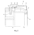
- Fig. 2 shows a schematic sectional view of a portion of the coupling system 10, 20 according to the invention.
- the coupling system 10, 20 has a coupling element 10, which may also be referred to as a coupling housing 10, and a locking element 20, which may also be referred to as a locking ring 20.
- the coupling element 10 and the locking element 20 are formed substantially cylindrical or annularly closed, are made of plastic and extend along a common longitudinal axis L.
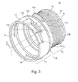
- Fig. 3 shows a perspective schematic representation of a coupling element 10 according to the invention.
- the coupling element 10 has a coupling body 11.
- the coupling body 11 has a first coupling region 12 and a second coupling region 16.
- the first coupling portion 12 serves to receive a Connection element 30 of an aggregate (see. Fig. 5 ).
- the connection element 30 may be an aggregate connection 30, for example based on the VDA standard, or a connector 30.
- the second coupling portion 16 serves to receive a hose or pipe, in particular made of plastic (not shown).
- the first coupling portion 12 is surrounded annularly by the locking element 20.
- the first coupling region 12 and the second coupling region 16 are connected by a conical transition region 19, the diameter of the coupling body 11 decreasing from the first coupling region 12 to the second coupling region 16.
- the coupling body 11 has in its first coupling portion 12 has three recesses 14 which extend in the form of grooves 14 in the circumferential direction.
- the recesses 14 are arranged distributed equidistantly in the circumferential direction, i. offset by 120 °, and connect the interior of the coupling body 11 with its external environment.
- Each recess 14 has an oblique edge 14 a, which extends in both the circumferential direction and in the radial direction R, and a vertical edge 14 b, which extends only in the radial direction R.
- the coupling body 11 also has a first radial elevation 13a as the first securing element 13a, which extends radially outwards from the conical transition area 19.
- the coupling body 11 also has a second radial elevation 13b as a second securing element 13b, which extends radially outward in the first coupling region 12 and is positioned in the circumferential direction such that it lies directly opposite the first radial elevation 13a in the longitudinal direction L.
- the coupling body 11 also has third radial elevations 13c as third securing elements 13c, which extend in the circumferential direction directly along the recesses 14 from their second edges 14b to approximately the middle of the recesses 14.
- the coupling body 11 further comprises a first marking element 15a, which is mounted on its surface visible from the outside and extends in the longitudinal direction L.
- the coupling body 11 At its second coupling region 16, the coupling body 11 has a second radial elevation 17 in the form of a bead 17 which extends closed in the circumferential direction. Between the bead 17 and the conical transition region 19, the coupling body 11 has a profiling 18 in the form of a corrugation 18.
- the bead 17 and the corrugation 18 serve to receive a plugged hose (not shown) and are intended to effect by increasing the frictional forces, so that the hose can not be deducted from the coupling body 11.
- the hose can be secured to the corrugation 18 by means of a press ring, a hose clamp or a plastic extrusion.
- a plastic pipe can also be welded directly to the conical transition region 19, so that the second coupling region 16 with corrugation 18 and bead 17 can be dispensed with.
- Fig. 4 shows a perspective schematic representation of a locking element 20 according to the invention.
- the locking element 20 has an annular locking body 21. Of the locking body 21 extend in the longitudinal direction L three spring elements 22, which may also be referred to as webs 22. The spring elements 22 are partially separated in the circumferential direction by extending in the longitudinal direction L columns 23 from the locking body 21. The spring elements 22 have at their opposite end of the locking body 21 an engagement element 24, which may also be referred to as a nose 24 or hook 24 and which extends radially inwardly.
- Each engagement element 24 has in the circumferential direction on one side an oblique edge 26 and on the opposite side a vertical edge 27.
- each engagement element 24 On its outer side, each engagement element 24 has a second marking element 25a, which is visually recognizable from the outside and which extends in the longitudinal direction L.
- each engagement element 24 On its inner side, each engagement element 24 has a first elevation 28 extending in the circumferential direction and extending radially inward in the form of a first edge 28.
- Each first elevation 28 has a radially inward-pointing second elevation 25b in the form of a second edge 25b, which extends in the longitudinal direction L and the oblique edge 26, the engagement element 24 in the longitudinal direction L is arranged opposite.
- the coupling element 10 and the locking element 20 cooperate as follows (cf. Fig. 1 ):
- the locking body 21 is disposed in the first coupling portion 12 of the coupling body 11 around this.
- the locking body 21 in the axial direction, i. positioned and held in the longitudinal direction L between the first radial elevation 13a and the second radial elevation 13b of the coupling body 11, so that axial displacements are not at all or at most minimally possible.
- This positioning is done such that the engagement members 24 and the recesses 14 are on the same circumference.
- In the circumferential direction of the locking body 21 is movable relative to the coupling body 11 by a rotational movement.
- the engagement element 24 are located outside the recesses 14 or within the recesses 14, but without protruding into the interior of the coupling body 11.
- the engagement members 24 are located outside of the recesses 14 so that they are pressed against the coupling body 11.
- the spring elements 22 are resiliently tensioned.
- the interior of the coupling body 11 is free of the engagement element 24, so that a connection element 30 (cf. Fig. 5 ) can be inserted into the first coupling portion 12.
- the locking body 21 is rotated clockwise in the direction of the tube in such a way that its engagement element 24 is guided into the recesses 14 and behind a first radial elevation 32 of the latter Connection body 31 of the connection element 30 (see. Fig. 5 ) and this block form-locking in the longitudinal direction L.
- the engagement element 24 are pressed by the spring force of the tensioned spring elements 22 radially inwardly through the recesses 14 therethrough.
- the oblique edges 26 of the engagement elements 24 and the corresponding oblique edges 14a of the slide Recesses 14 from each other until the engagement elements 24 have fully engaged in the recesses 14.
- the rotational movement ends when the vertical edges 27 of the engagement elements 24 abut against the vertical edges 14b of the recesses 14.
- the connecting element 30 is blocked by the coupling system 10, 20 longitudinal direction L.
- the second position of the rotational movement as a locking position or locking position engage the second elevation 25b of the spring elements 22 in the corresponding recesses 15b of the coupling body 11, so that the second position of the rotational movement only with increased force against the latched in the recesses 15b surveys 25b and the spring action of the spring elements 22 can solve again.
- the first marking element 15 a and the second marking element 25a exactly opposite, so that from the outside, the secured second position of the rotational movement can be optically detected.
- the engagement elements 24 and the first protrusions 28 of the spring elements 22 enclose the third radial elevations 13c in the longitudinal direction L from both sides.
- the play between recesses 14 and engagement elements 24 can be minimized and the stability of the securing of the connection element 30 can be increased.
- a release of this compound of the coupling system 10, 20 is still possible by rotational movement.
- serve the oblique edges 26 of the engagement elements 24 and the oblique edges 14b of the recesses 14, on which the engagement elements 24 are moved by a rotational movement from the viewing direction of the hose counterclockwise back to the first position of the rotational movement out of the recesses 24 out can.
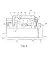
- Fig. 5 shows a schematic sectional view of the coupling system 10, 20 according to the invention with connection element 30.
- the connection body 31 of Connecting element 30 (VDA connecting piece 30) is thereby secured by the engagement elements 24 in the interior of the coupling body 11.
- the engagement elements 24 engage behind the first radial elevation 32 of the connection body 31, which can also be referred to as the first bead 32.
- the connecting body 31 abuts with its end and / or with its first radial elevation 32 in the longitudinal direction L against the interior of the coupling body 11.
- the connecting body 31 further comprises a second radial elevation 33rd in the form of a second bead 33 which is arranged opposite the engagement elements 24 in the longitudinal direction L such that the first radial elevation 32 and the second radial elevation 33 in the secured second position enclose the engagement elements 24 in the longitudinal direction L on both sides.
- Fig. 6 shows a part of the Fig. 5 ,
- a sealing element 40 is shown, which is formed as an O-ring or as a 2-lip system and is arranged radially between the inside of the coupling body 11 and the outside of the connection body 31, around these two bodies 11 , 31 fluid-tight seal against each other.
- a blocking element 50 in the form of a locking ring 50 is provided, which bears radially on the inside of the coupling body 11 and secures the sealing element 40 in the longitudinal direction L.
- the blocking element 50 is welded or molded onto the coupling body 11 as a plastic part.
Landscapes
- Engineering & Computer Science (AREA)
- General Engineering & Computer Science (AREA)
- Mechanical Engineering (AREA)
- Quick-Acting Or Multi-Walled Pipe Joints (AREA)
Applications Claiming Priority (1)
| Application Number | Priority Date | Filing Date | Title |
|---|---|---|---|
| DE102014217141.5A DE102014217141A1 (de) | 2014-08-28 | 2014-08-28 | Kupplungssystem zur Verbindung zweier medienführender Elemente |
Publications (2)
| Publication Number | Publication Date |
|---|---|
| EP2990708A1 true EP2990708A1 (fr) | 2016-03-02 |
| EP2990708B1 EP2990708B1 (fr) | 2018-05-09 |
Family
ID=53433009
Family Applications (1)
| Application Number | Title | Priority Date | Filing Date |
|---|---|---|---|
| EP15171315.3A Active EP2990708B1 (fr) | 2014-08-28 | 2015-06-10 | Système de couplage de deux elements de transport de fluide |
Country Status (2)
| Country | Link |
|---|---|
| EP (1) | EP2990708B1 (fr) |
| DE (1) | DE102014217141A1 (fr) |
Cited By (5)
| Publication number | Priority date | Publication date | Assignee | Title |
|---|---|---|---|---|
| WO2018007241A1 (fr) * | 2016-07-07 | 2018-01-11 | Norma Germany Gmbh | Accouplement pour conduite de fluide |
| DE102016123200A1 (de) * | 2016-12-01 | 2018-06-07 | Airbus Operations Gmbh | Rohrendstück mit einem Anschlussmechanismus |
| JP2019066033A (ja) * | 2017-08-31 | 2019-04-25 | ノルマ ジャーマニー ゲーエムベーハー | コネクタ |
| WO2019121050A1 (fr) * | 2017-12-22 | 2019-06-27 | Norma Germany Gmbh | Accouplement pour conduite de fluide |
| DE102019102119A1 (de) | 2019-01-29 | 2020-07-30 | Mann+Hummel Gmbh | Kupplungssystem zur Verbindung zweier Rohrabschnitte |
Families Citing this family (2)
| Publication number | Priority date | Publication date | Assignee | Title |
|---|---|---|---|---|
| DE102019105115A1 (de) * | 2019-02-28 | 2020-09-03 | PSZ electronic GmbH | Vorrichtung zur Befestigung von Schlauch- und Kabelsätzen |
| AT525974B1 (de) * | 2022-09-27 | 2023-10-15 | Henn Gmbh & Co Kg | Steckverbinder zum Verbinden von Leitungen für flüssige oder gasförmige Medien, sowie ein Verfahren zum Herstellen einer Steckverbindung zwischen dem Steckverbinder und einem Gegensteckverbinder |
Citations (6)
| Publication number | Priority date | Publication date | Assignee | Title |
|---|---|---|---|---|
| EP0452172A1 (fr) * | 1990-03-29 | 1991-10-16 | Hutchinson S.A. | Dispositif d'assemblage rapide par encliquetage pour échangeurs de chaleur de véhicules automobiles |
| DE4107603C1 (fr) * | 1991-03-09 | 1992-02-06 | Rasmussen Gmbh, 6457 Maintal, De | |
| DE10030274A1 (de) * | 2000-06-20 | 2002-01-03 | Bosch Gmbh Robert | Kupplungssystem für Bauteile |
| DE10055348A1 (de) | 2000-11-08 | 2002-05-23 | Henn Ges M B H & Co Kg Dornbir | Verfahren zur Herstellung einer Schlauchsteckverbindung und danach hergestellte Schlauchsteckverbindung |
| US20070120362A1 (en) * | 2003-12-10 | 2007-05-31 | Legris Sa | Quick coupling device |
| WO2014056652A1 (fr) * | 2012-10-10 | 2014-04-17 | Mahle International Gmbh | Dispositif de raccordement destiné à un système d'alimentation en air frais |
-
2014
- 2014-08-28 DE DE102014217141.5A patent/DE102014217141A1/de not_active Withdrawn
-
2015
- 2015-06-10 EP EP15171315.3A patent/EP2990708B1/fr active Active
Patent Citations (6)
| Publication number | Priority date | Publication date | Assignee | Title |
|---|---|---|---|---|
| EP0452172A1 (fr) * | 1990-03-29 | 1991-10-16 | Hutchinson S.A. | Dispositif d'assemblage rapide par encliquetage pour échangeurs de chaleur de véhicules automobiles |
| DE4107603C1 (fr) * | 1991-03-09 | 1992-02-06 | Rasmussen Gmbh, 6457 Maintal, De | |
| DE10030274A1 (de) * | 2000-06-20 | 2002-01-03 | Bosch Gmbh Robert | Kupplungssystem für Bauteile |
| DE10055348A1 (de) | 2000-11-08 | 2002-05-23 | Henn Ges M B H & Co Kg Dornbir | Verfahren zur Herstellung einer Schlauchsteckverbindung und danach hergestellte Schlauchsteckverbindung |
| US20070120362A1 (en) * | 2003-12-10 | 2007-05-31 | Legris Sa | Quick coupling device |
| WO2014056652A1 (fr) * | 2012-10-10 | 2014-04-17 | Mahle International Gmbh | Dispositif de raccordement destiné à un système d'alimentation en air frais |
Cited By (9)
| Publication number | Priority date | Publication date | Assignee | Title |
|---|---|---|---|---|
| WO2018007241A1 (fr) * | 2016-07-07 | 2018-01-11 | Norma Germany Gmbh | Accouplement pour conduite de fluide |
| CN109416143A (zh) * | 2016-07-07 | 2019-03-01 | 德国诺玛公司 | 用于流体管路的连接器 |
| JP2019520533A (ja) * | 2016-07-07 | 2019-07-18 | ノルマ ジャーマニー ゲーエムベーハー | 流体ラインのためのコネクター |
| CN109416143B (zh) * | 2016-07-07 | 2020-12-25 | 德国诺玛公司 | 用于流体管路的连接器 |
| US11125370B2 (en) | 2016-07-07 | 2021-09-21 | Norma Germany Gmbh | Connector for a fluid line |
| DE102016123200A1 (de) * | 2016-12-01 | 2018-06-07 | Airbus Operations Gmbh | Rohrendstück mit einem Anschlussmechanismus |
| JP2019066033A (ja) * | 2017-08-31 | 2019-04-25 | ノルマ ジャーマニー ゲーエムベーハー | コネクタ |
| WO2019121050A1 (fr) * | 2017-12-22 | 2019-06-27 | Norma Germany Gmbh | Accouplement pour conduite de fluide |
| DE102019102119A1 (de) | 2019-01-29 | 2020-07-30 | Mann+Hummel Gmbh | Kupplungssystem zur Verbindung zweier Rohrabschnitte |
Also Published As
| Publication number | Publication date |
|---|---|
| DE102014217141A1 (de) | 2016-03-03 |
| EP2990708B1 (fr) | 2018-05-09 |
Similar Documents
| Publication | Publication Date | Title |
|---|---|---|
| EP2990708B1 (fr) | Système de couplage de deux elements de transport de fluide | |
| DE3879674T2 (de) | Schnellkupplung fuer rohre oder schlaeuche mit einem kegelfoermigen haltering. | |
| EP1939514A1 (fr) | Dispositif de liaison doté de raccords tubulaires destinés à relier des éléments de réception de fluide | |
| DE4309992A1 (de) | Verbinder für Rohre mit einem geringen Durchmesser | |
| EP2724065B1 (fr) | Raccord de tuyau flexible et système de tuyau flexible correspondant | |
| DE102011118099A1 (de) | Vorrichtung zum Verbinden zweier Leitungsabschnitte | |
| EP3631275B1 (fr) | Élément d'accouplement permettant de raccorder une première conduite de fluide à une deuxième conduite de fluide ainsi que dispositif d'accouplement | |
| DE69412148T2 (de) | Rohrförmige Kupplung | |
| EP2466183A2 (fr) | Accouplement rapide pour conduites de fluide | |
| DE102017105858A1 (de) | Rohrkupplung | |
| EP2669561B1 (fr) | Dispositif de liaison de conduits | |
| EP3803180B1 (fr) | Dispositif de raccordement pour un ensemble de tuyaux souples | |
| DE102014111436A1 (de) | Kupplungsanordnung, insbesondere Rohrkupplung | |
| EP2193303A1 (fr) | Raccord à presser pour un tube, notamment pour un tube plastique ou tuyau composite constitué de plastique et de métal | |
| CH619524A5 (en) | Releasable pipe connection, especially for plastic pipes | |
| WO2019185783A1 (fr) | Dispositif de raccordement pour conduites de fluide | |
| DE102010004053A1 (de) | Schlauchkupplung | |
| DE102008050073A1 (de) | Anschluss für ein Rohr | |
| DE102009033247B3 (de) | Kupplung mit Ausklinkungen | |
| EP3557108A1 (fr) | Dispositif de raccordement pour conduites de fluide | |
| DE102012214035A1 (de) | Verbindungsanordnung für Druckleitungen | |
| EP2476939A2 (fr) | Raccord pour le raccordement d'une extrémité de tuyau | |
| CH696250A5 (de) | Verbindungselement zum Verbinden von zwei Wellrohren. | |
| DE102007063641B4 (de) | Verbindungsanordnung für den Installationsbereich | |
| WO2016058791A1 (fr) | Dispositif d'assemblage de tuyaux |
Legal Events
| Date | Code | Title | Description |
|---|---|---|---|
| PUAI | Public reference made under article 153(3) epc to a published international application that has entered the european phase |
Free format text: ORIGINAL CODE: 0009012 |
|
| AK | Designated contracting states |
Kind code of ref document: A1 Designated state(s): AL AT BE BG CH CY CZ DE DK EE ES FI FR GB GR HR HU IE IS IT LI LT LU LV MC MK MT NL NO PL PT RO RS SE SI SK SM TR |
|
| AX | Request for extension of the european patent |
Extension state: BA ME |
|
| 17P | Request for examination filed |
Effective date: 20160902 |
|
| RBV | Designated contracting states (corrected) |
Designated state(s): AL AT BE BG CH CY CZ DE DK EE ES FI FR GB GR HR HU IE IS IT LI LT LU LV MC MK MT NL NO PL PT RO RS SE SI SK SM TR |
|
| GRAP | Despatch of communication of intention to grant a patent |
Free format text: ORIGINAL CODE: EPIDOSNIGR1 |
|
| GRAJ | Information related to disapproval of communication of intention to grant by the applicant or resumption of examination proceedings by the epo deleted |
Free format text: ORIGINAL CODE: EPIDOSDIGR1 |
|
| RIC1 | Information provided on ipc code assigned before grant |
Ipc: F16L 37/10 20060101AFI20170316BHEP Ipc: F02M 35/10 20060101ALN20170316BHEP |
|
| GRAP | Despatch of communication of intention to grant a patent |
Free format text: ORIGINAL CODE: EPIDOSNIGR1 |
|
| INTG | Intention to grant announced |
Effective date: 20170410 |
|
| GRAJ | Information related to disapproval of communication of intention to grant by the applicant or resumption of examination proceedings by the epo deleted |
Free format text: ORIGINAL CODE: EPIDOSDIGR1 |
|
| GRAP | Despatch of communication of intention to grant a patent |
Free format text: ORIGINAL CODE: EPIDOSNIGR1 |
|
| INTG | Intention to grant announced |
Effective date: 20170426 |
|
| GRAJ | Information related to disapproval of communication of intention to grant by the applicant or resumption of examination proceedings by the epo deleted |
Free format text: ORIGINAL CODE: EPIDOSDIGR1 |
|
| GRAP | Despatch of communication of intention to grant a patent |
Free format text: ORIGINAL CODE: EPIDOSNIGR1 |
|
| INTG | Intention to grant announced |
Effective date: 20170523 |
|
| GRAJ | Information related to disapproval of communication of intention to grant by the applicant or resumption of examination proceedings by the epo deleted |
Free format text: ORIGINAL CODE: EPIDOSDIGR1 |
|
| GRAP | Despatch of communication of intention to grant a patent |
Free format text: ORIGINAL CODE: EPIDOSNIGR1 |
|
| INTG | Intention to grant announced |
Effective date: 20170619 |
|
| GRAJ | Information related to disapproval of communication of intention to grant by the applicant or resumption of examination proceedings by the epo deleted |
Free format text: ORIGINAL CODE: EPIDOSDIGR1 |
|
| GRAP | Despatch of communication of intention to grant a patent |
Free format text: ORIGINAL CODE: EPIDOSNIGR1 |
|
| INTG | Intention to grant announced |
Effective date: 20170711 |
|
| INTG | Intention to grant announced |
Effective date: 20170726 |
|
| GRAJ | Information related to disapproval of communication of intention to grant by the applicant or resumption of examination proceedings by the epo deleted |
Free format text: ORIGINAL CODE: EPIDOSDIGR1 |
|
| GRAP | Despatch of communication of intention to grant a patent |
Free format text: ORIGINAL CODE: EPIDOSNIGR1 |
|
| GRAJ | Information related to disapproval of communication of intention to grant by the applicant or resumption of examination proceedings by the epo deleted |
Free format text: ORIGINAL CODE: EPIDOSDIGR1 |
|
| INTG | Intention to grant announced |
Effective date: 20170912 |
|
| GRAP | Despatch of communication of intention to grant a patent |
Free format text: ORIGINAL CODE: EPIDOSNIGR1 |
|
| INTC | Intention to grant announced (deleted) | ||
| RIC1 | Information provided on ipc code assigned before grant |
Ipc: F16L 37/10 20060101AFI20170922BHEP Ipc: F02M 35/10 20060101ALN20170922BHEP |
|
| INTG | Intention to grant announced |
Effective date: 20171016 |
|
| GRAS | Grant fee paid |
Free format text: ORIGINAL CODE: EPIDOSNIGR3 |
|
| GRAA | (expected) grant |
Free format text: ORIGINAL CODE: 0009210 |
|
| AK | Designated contracting states |
Kind code of ref document: B1 Designated state(s): AL AT BE BG CH CY CZ DE DK EE ES FI FR GB GR HR HU IE IS IT LI LT LU LV MC MK MT NL NO PL PT RO RS SE SI SK SM TR |
|
| REG | Reference to a national code |
Ref country code: GB Ref legal event code: FG4D Free format text: NOT ENGLISH |
|
| REG | Reference to a national code |
Ref country code: CH Ref legal event code: EP Ref country code: AT Ref legal event code: REF Ref document number: 997890 Country of ref document: AT Kind code of ref document: T Effective date: 20180515 |
|
| REG | Reference to a national code |
Ref country code: IE Ref legal event code: FG4D Free format text: LANGUAGE OF EP DOCUMENT: GERMAN |
|
| REG | Reference to a national code |
Ref country code: DE Ref legal event code: R096 Ref document number: 502015004176 Country of ref document: DE |
|
| REG | Reference to a national code |
Ref country code: FR Ref legal event code: PLFP Year of fee payment: 4 |
|
| REG | Reference to a national code |
Ref country code: NL Ref legal event code: MP Effective date: 20180509 |
|
| REG | Reference to a national code |
Ref country code: LT Ref legal event code: MG4D |
|
| PG25 | Lapsed in a contracting state [announced via postgrant information from national office to epo] |
Ref country code: NO Free format text: LAPSE BECAUSE OF FAILURE TO SUBMIT A TRANSLATION OF THE DESCRIPTION OR TO PAY THE FEE WITHIN THE PRESCRIBED TIME-LIMIT Effective date: 20180809 Ref country code: BG Free format text: LAPSE BECAUSE OF FAILURE TO SUBMIT A TRANSLATION OF THE DESCRIPTION OR TO PAY THE FEE WITHIN THE PRESCRIBED TIME-LIMIT Effective date: 20180809 Ref country code: LT Free format text: LAPSE BECAUSE OF FAILURE TO SUBMIT A TRANSLATION OF THE DESCRIPTION OR TO PAY THE FEE WITHIN THE PRESCRIBED TIME-LIMIT Effective date: 20180509 Ref country code: FI Free format text: LAPSE BECAUSE OF FAILURE TO SUBMIT A TRANSLATION OF THE DESCRIPTION OR TO PAY THE FEE WITHIN THE PRESCRIBED TIME-LIMIT Effective date: 20180509 Ref country code: ES Free format text: LAPSE BECAUSE OF FAILURE TO SUBMIT A TRANSLATION OF THE DESCRIPTION OR TO PAY THE FEE WITHIN THE PRESCRIBED TIME-LIMIT Effective date: 20180509 Ref country code: SE Free format text: LAPSE BECAUSE OF FAILURE TO SUBMIT A TRANSLATION OF THE DESCRIPTION OR TO PAY THE FEE WITHIN THE PRESCRIBED TIME-LIMIT Effective date: 20180509 |
|
| PG25 | Lapsed in a contracting state [announced via postgrant information from national office to epo] |
Ref country code: HR Free format text: LAPSE BECAUSE OF FAILURE TO SUBMIT A TRANSLATION OF THE DESCRIPTION OR TO PAY THE FEE WITHIN THE PRESCRIBED TIME-LIMIT Effective date: 20180509 Ref country code: LV Free format text: LAPSE BECAUSE OF FAILURE TO SUBMIT A TRANSLATION OF THE DESCRIPTION OR TO PAY THE FEE WITHIN THE PRESCRIBED TIME-LIMIT Effective date: 20180509 Ref country code: RS Free format text: LAPSE BECAUSE OF FAILURE TO SUBMIT A TRANSLATION OF THE DESCRIPTION OR TO PAY THE FEE WITHIN THE PRESCRIBED TIME-LIMIT Effective date: 20180509 Ref country code: NL Free format text: LAPSE BECAUSE OF FAILURE TO SUBMIT A TRANSLATION OF THE DESCRIPTION OR TO PAY THE FEE WITHIN THE PRESCRIBED TIME-LIMIT Effective date: 20180509 Ref country code: GR Free format text: LAPSE BECAUSE OF FAILURE TO SUBMIT A TRANSLATION OF THE DESCRIPTION OR TO PAY THE FEE WITHIN THE PRESCRIBED TIME-LIMIT Effective date: 20180810 |
|
| PG25 | Lapsed in a contracting state [announced via postgrant information from national office to epo] |
Ref country code: DK Free format text: LAPSE BECAUSE OF FAILURE TO SUBMIT A TRANSLATION OF THE DESCRIPTION OR TO PAY THE FEE WITHIN THE PRESCRIBED TIME-LIMIT Effective date: 20180509 Ref country code: PL Free format text: LAPSE BECAUSE OF FAILURE TO SUBMIT A TRANSLATION OF THE DESCRIPTION OR TO PAY THE FEE WITHIN THE PRESCRIBED TIME-LIMIT Effective date: 20180509 Ref country code: EE Free format text: LAPSE BECAUSE OF FAILURE TO SUBMIT A TRANSLATION OF THE DESCRIPTION OR TO PAY THE FEE WITHIN THE PRESCRIBED TIME-LIMIT Effective date: 20180509 Ref country code: CZ Free format text: LAPSE BECAUSE OF FAILURE TO SUBMIT A TRANSLATION OF THE DESCRIPTION OR TO PAY THE FEE WITHIN THE PRESCRIBED TIME-LIMIT Effective date: 20180509 Ref country code: RO Free format text: LAPSE BECAUSE OF FAILURE TO SUBMIT A TRANSLATION OF THE DESCRIPTION OR TO PAY THE FEE WITHIN THE PRESCRIBED TIME-LIMIT Effective date: 20180509 Ref country code: SK Free format text: LAPSE BECAUSE OF FAILURE TO SUBMIT A TRANSLATION OF THE DESCRIPTION OR TO PAY THE FEE WITHIN THE PRESCRIBED TIME-LIMIT Effective date: 20180509 |
|
| REG | Reference to a national code |
Ref country code: CH Ref legal event code: PL |
|
| REG | Reference to a national code |
Ref country code: DE Ref legal event code: R097 Ref document number: 502015004176 Country of ref document: DE |
|
| PG25 | Lapsed in a contracting state [announced via postgrant information from national office to epo] |
Ref country code: SM Free format text: LAPSE BECAUSE OF FAILURE TO SUBMIT A TRANSLATION OF THE DESCRIPTION OR TO PAY THE FEE WITHIN THE PRESCRIBED TIME-LIMIT Effective date: 20180509 Ref country code: IT Free format text: LAPSE BECAUSE OF FAILURE TO SUBMIT A TRANSLATION OF THE DESCRIPTION OR TO PAY THE FEE WITHIN THE PRESCRIBED TIME-LIMIT Effective date: 20180509 |
|
| REG | Reference to a national code |
Ref country code: BE Ref legal event code: MM Effective date: 20180630 |
|
| PLBE | No opposition filed within time limit |
Free format text: ORIGINAL CODE: 0009261 |
|
| STAA | Information on the status of an ep patent application or granted ep patent |
Free format text: STATUS: NO OPPOSITION FILED WITHIN TIME LIMIT |
|
| REG | Reference to a national code |
Ref country code: IE Ref legal event code: MM4A |
|
| PG25 | Lapsed in a contracting state [announced via postgrant information from national office to epo] |
Ref country code: MC Free format text: LAPSE BECAUSE OF FAILURE TO SUBMIT A TRANSLATION OF THE DESCRIPTION OR TO PAY THE FEE WITHIN THE PRESCRIBED TIME-LIMIT Effective date: 20180509 Ref country code: LU Free format text: LAPSE BECAUSE OF NON-PAYMENT OF DUE FEES Effective date: 20180610 |
|
| 26N | No opposition filed |
Effective date: 20190212 |
|
| PG25 | Lapsed in a contracting state [announced via postgrant information from national office to epo] |
Ref country code: LI Free format text: LAPSE BECAUSE OF NON-PAYMENT OF DUE FEES Effective date: 20180630 Ref country code: CH Free format text: LAPSE BECAUSE OF NON-PAYMENT OF DUE FEES Effective date: 20180630 Ref country code: IE Free format text: LAPSE BECAUSE OF NON-PAYMENT OF DUE FEES Effective date: 20180610 |
|
| PG25 | Lapsed in a contracting state [announced via postgrant information from national office to epo] |
Ref country code: BE Free format text: LAPSE BECAUSE OF NON-PAYMENT OF DUE FEES Effective date: 20180630 Ref country code: SI Free format text: LAPSE BECAUSE OF FAILURE TO SUBMIT A TRANSLATION OF THE DESCRIPTION OR TO PAY THE FEE WITHIN THE PRESCRIBED TIME-LIMIT Effective date: 20180509 |
|
| PG25 | Lapsed in a contracting state [announced via postgrant information from national office to epo] |
Ref country code: AL Free format text: LAPSE BECAUSE OF FAILURE TO SUBMIT A TRANSLATION OF THE DESCRIPTION OR TO PAY THE FEE WITHIN THE PRESCRIBED TIME-LIMIT Effective date: 20180509 |
|
| PG25 | Lapsed in a contracting state [announced via postgrant information from national office to epo] |
Ref country code: MT Free format text: LAPSE BECAUSE OF FAILURE TO SUBMIT A TRANSLATION OF THE DESCRIPTION OR TO PAY THE FEE WITHIN THE PRESCRIBED TIME-LIMIT Effective date: 20180509 |
|
| PG25 | Lapsed in a contracting state [announced via postgrant information from national office to epo] |
Ref country code: TR Free format text: LAPSE BECAUSE OF FAILURE TO SUBMIT A TRANSLATION OF THE DESCRIPTION OR TO PAY THE FEE WITHIN THE PRESCRIBED TIME-LIMIT Effective date: 20180509 |
|
| PG25 | Lapsed in a contracting state [announced via postgrant information from national office to epo] |
Ref country code: PT Free format text: LAPSE BECAUSE OF FAILURE TO SUBMIT A TRANSLATION OF THE DESCRIPTION OR TO PAY THE FEE WITHIN THE PRESCRIBED TIME-LIMIT Effective date: 20180509 |
|
| PG25 | Lapsed in a contracting state [announced via postgrant information from national office to epo] |
Ref country code: MK Free format text: LAPSE BECAUSE OF NON-PAYMENT OF DUE FEES Effective date: 20180509 Ref country code: HU Free format text: LAPSE BECAUSE OF FAILURE TO SUBMIT A TRANSLATION OF THE DESCRIPTION OR TO PAY THE FEE WITHIN THE PRESCRIBED TIME-LIMIT; INVALID AB INITIO Effective date: 20150610 Ref country code: CY Free format text: LAPSE BECAUSE OF FAILURE TO SUBMIT A TRANSLATION OF THE DESCRIPTION OR TO PAY THE FEE WITHIN THE PRESCRIBED TIME-LIMIT Effective date: 20180509 |
|
| PG25 | Lapsed in a contracting state [announced via postgrant information from national office to epo] |
Ref country code: IS Free format text: LAPSE BECAUSE OF FAILURE TO SUBMIT A TRANSLATION OF THE DESCRIPTION OR TO PAY THE FEE WITHIN THE PRESCRIBED TIME-LIMIT Effective date: 20180909 |
|
| REG | Reference to a national code |
Ref country code: AT Ref legal event code: MM01 Ref document number: 997890 Country of ref document: AT Kind code of ref document: T Effective date: 20200610 |
|
| PG25 | Lapsed in a contracting state [announced via postgrant information from national office to epo] |
Ref country code: AT Free format text: LAPSE BECAUSE OF NON-PAYMENT OF DUE FEES Effective date: 20200610 |
|
| PGFP | Annual fee paid to national office [announced via postgrant information from national office to epo] |
Ref country code: DE Payment date: 20230630 Year of fee payment: 9 |
|
| REG | Reference to a national code |
Ref country code: DE Ref legal event code: R081 Ref document number: 502015004176 Country of ref document: DE Owner name: CONTITECH TECHNO-CHEMIE GMBH, DE Free format text: FORMER OWNER: CONTITECH MGW GMBH, 34346 HANN. MUENDEN, DE |
|
| PGFP | Annual fee paid to national office [announced via postgrant information from national office to epo] |
Ref country code: GB Payment date: 20240620 Year of fee payment: 10 |
|
| PGFP | Annual fee paid to national office [announced via postgrant information from national office to epo] |
Ref country code: FR Payment date: 20240628 Year of fee payment: 10 |