EP2990600A1 - Gasturbinen-Baugruppe - Google Patents
Gasturbinen-Baugruppe Download PDFInfo
- Publication number
- EP2990600A1 EP2990600A1 EP14182761.8A EP14182761A EP2990600A1 EP 2990600 A1 EP2990600 A1 EP 2990600A1 EP 14182761 A EP14182761 A EP 14182761A EP 2990600 A1 EP2990600 A1 EP 2990600A1
- Authority
- EP
- European Patent Office
- Prior art keywords
- turbine
- turbine housing
- axial
- circumferential position
- housing
- Prior art date
- Legal status (The legal status is an assumption and is not a legal conclusion. Google has not performed a legal analysis and makes no representation as to the accuracy of the status listed.)
- Granted
Links
- 238000001816 cooling Methods 0.000 claims abstract description 13
- 238000002485 combustion reaction Methods 0.000 claims abstract description 4
- 238000011144 upstream manufacturing Methods 0.000 claims description 26
- 230000002093 peripheral effect Effects 0.000 claims description 10
- 238000004519 manufacturing process Methods 0.000 claims description 7
- 230000004323 axial length Effects 0.000 claims description 5
- 238000011161 development Methods 0.000 description 11
- 230000018109 developmental process Effects 0.000 description 11
- 230000000903 blocking effect Effects 0.000 description 2
- 230000001419 dependent effect Effects 0.000 description 2
- 238000009826 distribution Methods 0.000 description 2
- 239000002184 metal Substances 0.000 description 2
- 238000007664 blowing Methods 0.000 description 1
- 238000010276 construction Methods 0.000 description 1
- 238000012986 modification Methods 0.000 description 1
- 230000004048 modification Effects 0.000 description 1
- 238000005476 soldering Methods 0.000 description 1
- 239000007787 solid Substances 0.000 description 1
- 238000003466 welding Methods 0.000 description 1
Images
Classifications
-
- F—MECHANICAL ENGINEERING; LIGHTING; HEATING; WEAPONS; BLASTING
- F02—COMBUSTION ENGINES; HOT-GAS OR COMBUSTION-PRODUCT ENGINE PLANTS
- F02C—GAS-TURBINE PLANTS; AIR INTAKES FOR JET-PROPULSION PLANTS; CONTROLLING FUEL SUPPLY IN AIR-BREATHING JET-PROPULSION PLANTS
- F02C7/00—Features, components parts, details or accessories, not provided for in, or of interest apart form groups F02C1/00 - F02C6/00; Air intakes for jet-propulsion plants
- F02C7/12—Cooling of plants
- F02C7/16—Cooling of plants characterised by cooling medium
- F02C7/18—Cooling of plants characterised by cooling medium the medium being gaseous, e.g. air
-
- F—MECHANICAL ENGINEERING; LIGHTING; HEATING; WEAPONS; BLASTING
- F01—MACHINES OR ENGINES IN GENERAL; ENGINE PLANTS IN GENERAL; STEAM ENGINES
- F01D—NON-POSITIVE DISPLACEMENT MACHINES OR ENGINES, e.g. STEAM TURBINES
- F01D5/00—Blades; Blade-carrying members; Heating, heat-insulating, cooling or antivibration means on the blades or the members
- F01D5/12—Blades
- F01D5/14—Form or construction
- F01D5/141—Shape, i.e. outer, aerodynamic form
- F01D5/142—Shape, i.e. outer, aerodynamic form of the blades of successive rotor or stator blade-rows
- F01D5/143—Contour of the outer or inner working fluid flow path wall, i.e. shroud or hub contour
-
- F—MECHANICAL ENGINEERING; LIGHTING; HEATING; WEAPONS; BLASTING
- F01—MACHINES OR ENGINES IN GENERAL; ENGINE PLANTS IN GENERAL; STEAM ENGINES
- F01D—NON-POSITIVE DISPLACEMENT MACHINES OR ENGINES, e.g. STEAM TURBINES
- F01D25/00—Component parts, details, or accessories, not provided for in, or of interest apart from, other groups
- F01D25/08—Cooling; Heating; Heat-insulation
- F01D25/12—Cooling
-
- F—MECHANICAL ENGINEERING; LIGHTING; HEATING; WEAPONS; BLASTING
- F01—MACHINES OR ENGINES IN GENERAL; ENGINE PLANTS IN GENERAL; STEAM ENGINES
- F01D—NON-POSITIVE DISPLACEMENT MACHINES OR ENGINES, e.g. STEAM TURBINES
- F01D25/00—Component parts, details, or accessories, not provided for in, or of interest apart from, other groups
- F01D25/24—Casings; Casing parts, e.g. diaphragms, casing fastenings
- F01D25/26—Double casings; Measures against temperature strain in casings
-
- F—MECHANICAL ENGINEERING; LIGHTING; HEATING; WEAPONS; BLASTING
- F02—COMBUSTION ENGINES; HOT-GAS OR COMBUSTION-PRODUCT ENGINE PLANTS
- F02C—GAS-TURBINE PLANTS; AIR INTAKES FOR JET-PROPULSION PLANTS; CONTROLLING FUEL SUPPLY IN AIR-BREATHING JET-PROPULSION PLANTS
- F02C3/00—Gas-turbine plants characterised by the use of combustion products as the working fluid
- F02C3/04—Gas-turbine plants characterised by the use of combustion products as the working fluid having a turbine driving a compressor
-
- F—MECHANICAL ENGINEERING; LIGHTING; HEATING; WEAPONS; BLASTING
- F05—INDEXING SCHEMES RELATING TO ENGINES OR PUMPS IN VARIOUS SUBCLASSES OF CLASSES F01-F04
- F05D—INDEXING SCHEME FOR ASPECTS RELATING TO NON-POSITIVE-DISPLACEMENT MACHINES OR ENGINES, GAS-TURBINES OR JET-PROPULSION PLANTS
- F05D2220/00—Application
- F05D2220/30—Application in turbines
- F05D2220/32—Application in turbines in gas turbines
-
- F—MECHANICAL ENGINEERING; LIGHTING; HEATING; WEAPONS; BLASTING
- F05—INDEXING SCHEMES RELATING TO ENGINES OR PUMPS IN VARIOUS SUBCLASSES OF CLASSES F01-F04
- F05D—INDEXING SCHEME FOR ASPECTS RELATING TO NON-POSITIVE-DISPLACEMENT MACHINES OR ENGINES, GAS-TURBINES OR JET-PROPULSION PLANTS
- F05D2240/00—Components
- F05D2240/35—Combustors or associated equipment
-
- F—MECHANICAL ENGINEERING; LIGHTING; HEATING; WEAPONS; BLASTING
- F05—INDEXING SCHEMES RELATING TO ENGINES OR PUMPS IN VARIOUS SUBCLASSES OF CLASSES F01-F04
- F05D—INDEXING SCHEME FOR ASPECTS RELATING TO NON-POSITIVE-DISPLACEMENT MACHINES OR ENGINES, GAS-TURBINES OR JET-PROPULSION PLANTS
- F05D2260/00—Function
- F05D2260/20—Heat transfer, e.g. cooling
-
- Y—GENERAL TAGGING OF NEW TECHNOLOGICAL DEVELOPMENTS; GENERAL TAGGING OF CROSS-SECTIONAL TECHNOLOGIES SPANNING OVER SEVERAL SECTIONS OF THE IPC; TECHNICAL SUBJECTS COVERED BY FORMER USPC CROSS-REFERENCE ART COLLECTIONS [XRACs] AND DIGESTS
- Y02—TECHNOLOGIES OR APPLICATIONS FOR MITIGATION OR ADAPTATION AGAINST CLIMATE CHANGE
- Y02T—CLIMATE CHANGE MITIGATION TECHNOLOGIES RELATED TO TRANSPORTATION
- Y02T50/00—Aeronautics or air transport
- Y02T50/60—Efficient propulsion technologies, e.g. for aircraft
Definitions
- the present invention relates to an assembly for a gas turbine with a turbine and an adjacent intermediate housing, a gas turbine, in particular a gas turbine aircraft engine, with such an assembly and a method for producing such an assembly.
- An object of an embodiment of the present invention is to improve the operation and / or the manufacture of a gas turbine.
- Claims 10, 12 provide protection for a gas turbine with an assembly described herein or a method of making an assembly described herein.
- Advantageous embodiments of the invention are the subject of the dependent claims.
- a gas turbine particularly a gas turbine aircraft engine, includes an assembly described herein having a turbine housing and an intermediate housing downstream of the turbine housing, and another turbine housing adjacent the intermediate housing downstream.
- the one turbine housing is a turbine housing of a high-pressure turbine downstream of a combustor of the gas turbine, the other turbine housing a turbine housing of a low-pressure turbine or a mid-pressure turbine followed by a low-pressure turbine downstream.
- the one turbine housing is a turbine housing a medium-pressure turbine, the other turbine housing a turbine housing a low-pressure turbine.
- the turbine housings each include rotors having a plurality of circumferentially spaced blades that may be generally part of the turbine housing in an embodiment for more compact representation.
- a turbine housing in the context of the present invention is only a stationary or stationary component relative to the gas turbine or the intermediate housing without the rotatably mounted rotor in it.
- a rotor of the turbine housing or a rotor rotatably mounted in the turbine housing is coupled to a rotor of a compressor upstream of the combustion chamber and / or a rotor of the further turbine housing or a rotor rotatably mounted in the further turbine housing with a rotor of one Compressor coupled upstream another compressor.
- an assembly for a gas turbine in particular an assembly of a gas turbine described herein, a single- or multi-part turbine housing and a one- or multi-part intermediate housing, which is adjacent to the turbine housing downstream and a plurality of circumferentially spaced support ribs having.
- Turbine and intermediate housings define a flow channel for a working gas from a combustor of the gas turbine.
- the turbine housing on a radially outer and / or a radially inner boundary wall, which forms a turbine housing side portion of the flow channel and radially bounded.
- a radially inner boundary wall of the turbine housing can be formed, in particular, by a hub which is stationary or stationary relative to the gas turbine or the intermediate housing, or by a rotatably mounted rotor, in particular an inner shroud of a running lattice or of rotor blades.
- the intermediate housing on a radially inner and a radially outer boundary wall, which form an intermediate housing-side portion of the flow channel or limit radially.
- the support ribs are or become detachable or permanent, preferably cohesively, in particular integrally formed with the radially inner and / or outer boundary wall of the intermediate housing.
- the support ribs each have an upstream, in particular straight or inclined in the circumferential and / or axial direction, in particular curved front edge, a downstream trailing edge and two opposing side walls which connect these edges and in a design, in particular convex, to Flow channel are arched out, in which they are arranged.
- a cavity is formed between the turbine and the intermediate housing.
- this cavity is arranged radially outside of the flow channel. Additionally or alternatively, it may also be arranged radially inward of the flow channel.
- the cavity is or forms a cooling air channel, which communicates in a development with a cooling air supply of the gas turbine or connected and / or is provided or adapted to introduce cooling air into the flow channel.
- the cavity has a turbine housing-side end face, which is formed in a development by an axial, the intermediate housing facing end side of the turbine housing or is, and an intermediate housing side end, formed in a development by an axial, the turbine housing facing end side of the intermediate housing is or is, on or is bounded by this axially, wherein the two end faces of the cavity are axially spaced from each other, in particular, to form a radial gap, preferably the cooling air passage.
- the cavity has a flow-channel-side opening which in one embodiment communicates with the flow channel or is provided or arranged for this purpose, in particular for blowing cooling air into the flow channel.
- the cavity also serves to allow different thermal expansions between the areas separated by the cavity.
- This flow channel-side opening has a, in particular in the circumferential direction continuous, the turbine housing facing or turbine housing side edge contour and one, in particular axially and / or radially spaced therefrom and / or circumferentially continuous, the intermediate housing facing or intermediate housing side edge contour.
- the turbine housing side edge contour along the circumference changes continuously or in the circumferential direction kink-free, in particular meandering, preferably sinusoidal.
- the edge contour may also change discontinuously along the circumference, in particular in the circumferential direction have kinks or edges, preferably be formed sawtooth or trapezoidal.
- the turbine housing side edge contour of the opening changes along the circumference, according to one embodiment, a radially outer and / or inner boundary wall of the intermediate housing, the flow channel or the housing side flow channel portion radially outwardly or inwardly limited, at least in an axial section facing the turbine housing, in particular at least one leading edge of the boundary wall or of the intermediate housing-side flow channel section, being or becoming rotationally symmetrical radially and / or axially.
- This can improve the manufacture, assembly and / or flow characteristics of the intermediate housing.
- the turbine housing-side edge contour which changes in the circumferential direction or along the circumference, can be formed on the turbine housing itself or integrally therewith, in particular on an outlet edge of a radially outer and / or inner boundary wall of the turbine housing, which surrounds the flow channel or Turbine housing side flow channel section radially outwardly or inwardly limited.
- the boundary wall or trailing edge in a design according to urgeformt, in particular cast, and / or, in particular machined, be edited or.
- the turbine housing side edge contour is or is formed on a flange which, in particular releasably, preferably frictionally, or permanently, preferably cohesively, in particular by welding or soldering, is connected to the turbine housing or is.
- the flange is made in one embodiment separately from the turbine housing and then connected thereto. In particular, it may be a sheet-metal shaped part which is curved in the circumferential direction in a further development.
- the flange has two limbs inclined relative to one another, in particular by at least 60 ° and / or at most 120 °, in particular a first limb which, at least substantially, extends in the radial direction and is connected to the turbine housing, and a second leg, which extends, at least substantially, in the axial direction and is therefore referred to as the axial leg, and at the axial end facing away from the turbine housing, the turbine housing side edge contour is or is formed.
- the flange or limb in one embodiment according to urgeformt, reshaped and / or, in particular machined, be edited or be.
- the turbine housing side edge contour is formed on a separately manufactured and connected to the turbine housing flange is, in one embodiment, a radially outer and / or inner boundary wall of the turbine housing, the flow channel or turbine housing side flow channel section bounded radially outside or inside, at least in an axial portion facing the intermediate housing, in particular at least one outlet edge of the boundary wall or the turbine housing-side flow channel section to be radially and / or axially rotationally symmetrical or be.
- This can improve the manufacture, assembly and / or flow characteristics of the turbine housing.
- the turbine housing side edge contour changes periodically along the circumference or in the circumferential direction with a division of the support ribs or their distribution in the circumferential direction.
- maximum and / or minimum axial and / or radial extensions of the turbine housing-side edge contour may be distributed periodically along the circumference, one period corresponding to a pitch or period of the support ribs (distribution).
- a peripheral portion extends between a circumferential position of an upstream leading edge of a support rib and a circumferential position of an upstream leading edge of a circumferentially adjacent support rib.
- the leading edges of these two support ribs have a corresponding distance, to which reference is also made below
- the turbine housing side edge contour in one or more, preferably all such peripheral regions, at a first circumferential position of the circumferential position of the leading edge of a support rib by at most 20%, in particular at most 10%, preferably at most 5%, of the distance between the Circumferential positions of the leading edges of the two support ribs, a first axial extent downstream and / or a first radial extent away from the flow channel, and at a second circumferential position between the two support ribs spaced from the circumferential positions of the leading edges of the two support ribs by at least 30%, in particular at least 40%, preferably at least 45% of the distance between the circumferential positions of the leading edges the two support ribs is spaced, a second axial extent downstream and / or a second radial extent from the flow channel away.
- the first circumferential position is accordingly in a development, at least essentially, upstream of a support rib or the circumferential position of its leading edge, the second circumferential position corresponding in a development, at least substantially, in the middle between two adjacent support ribs and in the circumferential direction at the level of half pitch between two adjacent support ribs.
- an axial extent downstream is understood to mean, in particular, an axial position of the turbine housing-side edge contour at the first or second circumferential position, with a greater axial extent downstream of an axial position further downstream, in particular away from the turbine housing and / or toward the intermediate housing.
- a radial extension of the flow channel away in the present case is understood in particular a radial position of the turbine housing side edge contour at the first and second circumferential position, wherein a larger radial extent of a radially outer edge contour or the turbine housing side edge contour of a cavity disposed radially outward of the flow channel or is formed, from the flow channel away corresponds to a larger radial distance to a rotational axis of the gas turbine, a larger radial extent of a radially inner edge contour or the turbine housing side edge contour of a cavity, which is arranged radially inwardly of the flow channel or formed away from the flow channel a smaller radial distance to the axis of rotation.
- the first axial extent is greater than the second axial extent, in a further development, the first axial extent is a maximum axial extent and / or the second axial extent is a minimum axial extent downstream within the circumferential area.
- the turbine housing-side edge contour in one embodiment, at least substantially, upstream of one or more, in particular all, support ribs, each having a maximum axial extent or axial position downstream.
- the edge contour at least substantially, in the middle between one or more, in particular all, pairs of adjacent support ribs or in the circumferential direction at half height, each having a minimum axial extent or axial position downstream.
- the first radial extent away from the flow channel is smaller than the second radial extent away from the flow channel, in a development the first radial extent is a minimum radial extent and / or the second radial extent is a maximum radial extent away from the flow channel within the peripheral region.
- the radially outer turbine housing-side edge contour in one embodiment, at least substantially, upstream of one or more, in particular all, support ribs, each have a minimum radial extent away from the flow channel or a minimum radial distance to a rotational axis of the gas turbine.
- the radially outer edge contour at least substantially, in the middle between one or more, in particular all, pairs of adjacent support ribs or in the circumferential direction at half height, each have a maximum radial extent away from the flow channel or a maximum radial Have distance to the axis of rotation of the gas turbine.
- a radially inner turbine housing-side edge contour in one embodiment, at least substantially, upstream of one or more, in particular all, support ribs, a minimum radial extent away from the flow channel or a maximum radial distance to a rotational axis of the gas turbine.
- the radially inner edge contour at least substantially, in the middle between one or more, in particular all, pairs of adjacent support ribs or in the circumferential direction at half height, respectively have a maximum radial extent away from the flow channel or a minimum radial distance from the axis of rotation of the gas turbine.
- a quotient ⁇ x / L out or ratio between a difference ⁇ x I x max - x min
- ⁇ x kav is the minimum axial gap between the turbine and the intermediate housing side end wall of the cavity in hot operating condition (continuous operation ) of the engine.
- a quotient ⁇ r / L out or ratio between a difference ⁇ r
- this quotient or ratio in one embodiment is at most 0.4, in particular at most 0.3.
- Another aspect of the present invention relates to a method for producing an assembly described herein, wherein a turbine housing side edge contour described here is formed.
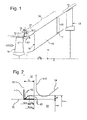
- Fig. 1 shows in DE 10 2011 008 812 A1 Similarly, two superimposed Meridian bain a assembly of a gas turbine according to an embodiment of the present invention with a turbine housing of a high- or medium-pressure turbine having a radially outer boundary wall 11 and in one embodiment, a rotor having a plurality of circumferentially spaced blades 10, and one Turbine housing downstream (right in Fig.
- intermediate housing having a radially outer boundary wall 14 and support ribs 15 which are integrally formed with the radially outer boundary wall 14 of the intermediate housing and each have an upstream leading edge 16 and a downstream trailing edge 17, and another turbine housing a medium or low pressure turbine of A gas turbine adjacent to the intermediate housing and having a radially outer boundary wall 13 and, in one embodiment, a rotor having a plurality of circumferentially spaced rotor blades 12.
- the rotors are generally referred to as a part of the turbine housing for more compact representation.
- a turbine housing in the context of the present invention only the stationary or stationary component relative to the gas turbine or the intermediate housing without the rotor rotatably mounted in it, in particular the radially outer boundary wall 11 and 13 respectively.
- the turbine and intermediate housings define a flow passage 33 for a working gas from a combustion chamber of the gas turbine, which in Fig. 1 Is indicated on the left by a horizontal arrow in the flow or axial direction. This is radially outwardly bounded radially by the radially outer boundary walls 11, 13 and 14 or the turbine and the intermediate housing. or formed.
- the cavity 19 forms a cooling air passage communicating with a cooling air supply of the gas turbine and is provided or adapted to cooling air 21 in to introduce the flow channel 33 and allow thermal expansions.
- the cavity 19 has a turbine housing side end face 19.1, which is formed by an axial, the intermediate housing facing end of the turbine housing, and an intermediate housing side end face 19.2, which is formed by an axial, the turbine housing facing end side of the intermediate housing on, wherein the two end faces 19.1 19, 19 of the cavity 19 are axially spaced apart to form the cooling air passage.
- Fig. 2 shows an in Fig. 1 Detail marked “II" in enlarged view.
- the cavity has a flow channel-side opening with a turbine housing-side edge contour 40.
- the flange is formed on a flange which is manufactured separately from the turbine housing as a sheet-metal shaped part and connected to the turbine housing.
- the flange has a first leg 41, which extends substantially in the radial direction r and is connected to the turbine housing, and a second or axial leg 42, which extends substantially in Axiahichtung x and is inclined to the first leg by about 90 ° and at the turbine housing facing away from the axial end face (right in Fig. 1 ) the turbine housing side edge contour 40 is formed.
- a rounded leading edge (left in Fig. 1 ) of the radially outer boundary wall 14 of the intermediate housing and a trailing edge (on the right in FIG Fig. 1 ) of the radially outer boundary wall 11 of the turbine housing are formed radially and axially rotationally symmetrical.
- a solid or drawn section is a meridian section in a first circumferential position, which is opposite to an upstream leading edge 16 of any support rib 15, this meridian section is the same for all supporting ribs.
- a dashed line section is a meridian section in a second circumferential position between any pair of circumferentially adjacent support ribs spaced from the circumferential positions of the leading edges of the two support ribs by 50% of the circumferential spacing between the circumferential positions of these leading edges, respectively this meridian section is the same for all centers between circumferentially adjacent support ribs. Subsequent embodiments therefore apply to all circumferential regions between each two circumferentially adjacent support ribs 15.
- the first circumferential position or the in Fig. 1, 2 shown meridian section is accordingly upstream on a support rib or the circumferential position of its leading edge, the second circumferential position or in Fig. 1, 2 dashed meridian section corresponding to in the middle between two adjacent support ribs or in the circumferential direction at the level of half the pitch between two adjacent support ribs.
- L denotes the maximum axial length of the axial leg 42, which at the same time represents the maximum axial distance between the edge contour 40 and the turbine housing-side end face 19.1 of the cavity 19.
- the turbine housing-side edge contour 40 changes continuously along the circumference or in the circumferential direction or kink-free, preferably meandering, in particular sinusoidal.
- the radially outer turbine housing side edge contour 40 thus changes along the circumference or circumferentially periodically with the pitch of the support ribs 15, wherein the edge contour respectively at one first circumferential position upstream of a leading edge of a support rib has a maximum axial extent x max downstream and a minimum radial extent away from the flow channel or a minimum radial distance to a rotational axis of the gas turbine r min .
- the edge contour Each at a second circumferential position in the middle between a pair of adjacent ones Supporting ribs respectively in the circumferential direction at the height of half the pitch 40, the edge contour, however, a minimum axial extension or axial position x min downstream and a maximum radial extent from the flow channel away or at a maximum radial distance from a rotational axis of the gas turbine r max on.
- the ratio between these extents is determined by the quotients ⁇ x / L and ⁇ r / L given above.
Landscapes
- Engineering & Computer Science (AREA)
- Mechanical Engineering (AREA)
- General Engineering & Computer Science (AREA)
- Physics & Mathematics (AREA)
- Fluid Mechanics (AREA)
- Chemical & Material Sciences (AREA)
- Combustion & Propulsion (AREA)
- Turbine Rotor Nozzle Sealing (AREA)
Abstract
einem Turbinengehäuse (11);
einem Zwischengehäuse (14), das dem Turbinengehäuse stromabwärts benachbart ist und eine Mehrzahl von in Umfangsrichtung beabstandeten Stützrippen (15) aufweist; wobei das Turbinen- und Zwischengehäuse einen Strömungskanal (33) für ein Arbeitsgas aus einer Brennkammer der Gasturbine definieren und zwischen dem Turbinen- und dem Zwischengehäuse eine Kavität, insbesondere ein Kühlluftkanal (19), mit einer strömungskanalseitigen Öffnung ausgebildet ist;
wobei eine turbinengehäuseseitige Randkontur (40) der Öffnung sich entlang des Umfangs radial und/oder axial verändert.
Description
- Die vorliegende Erfindung betrifft eine Baugruppe für eine Gasturbine mit einem Turbinen- und einem benachbarten Zwischengehäuse, eine Gasturbine, insbesondere ein Gasturbinenflugtriebwerk, mit einer solchen Baugruppe sowie ein Verfahren zum Herstellen einer solchen Baugruppe.
- Aus der
DE 10 2011 008 812 A1 ist ein Zwischengehäuse eines Gastriebwerks mit einer radial außenliegenden Begrenzungswand bekannt, die eine sich in Umfangsrichtung verändernde Kontur aufweist. Hierdurch kann einer Sekundärströmung in einer Kavität zwischen Turbinen- und Zwischengehäuse entgegengewirkt und so der Wirkungsgrad verbessert werden. - Eine Aufgabe einer Ausführung der vorliegenden Erfindung ist es, den Betrieb und/oder die Herstellung einer Gasturbine zu verbessern.
- Diese Aufgabe wird durch eine Baugruppe für eine Gasturbine mit den Merkmalen des Anspruchs 1 gelöst. Ansprüche 10, 12 stellen eine Gasturbine mit einer hier beschriebenen Baugruppe bzw. ein Verfahren zum Herstellen einer hier beschriebenen Baugruppe unter Schutz. Vorteilhafte Ausführungsformen der Erfindung sind Gegenstand der Unteransprüche.
- Nach einem Aspekt der vorliegenden Erfindung weist eine Gasturbine, insbesondere ein Gasturbinenflugtriebwerk, eine hier beschriebene Baugruppe mit einem Turbinengehäuse und einem dem Turbinengehäuse stromabwärts benachbarten Zwischengehäuse sowie ein weiteres Turbinengehäuse auf, das dem Zwischengehäuse stromabwärts benachbart ist. Das eine Turbinengehäuse ist in einer Ausführung ein Turbinengehäuse einer Hochdruckturbine, die stromabwärts auf eine Brennkammer der Gasturbine folgt, das weitere Turbinengehäuse ein Turbinengehäuse einer Niederdruckturbine oder einer Mitteldruckturbine, auf die stromabwärts eine Niederdruckturbine folgt. In einer anderen Ausführung ist das eine Turbinengehäuse ein Turbinengehäuse einer Mitteldruckturbine, das weitere Turbinengehäuse ein Turbinengehäuse einer Niederdruckturbine.
- In einer Ausführung weisen die Turbinengehäuse jeweils Rotoren mit einer Mehrzahl von in Umfangsrichtung beabstandeten Laufschaufeln auf, die in einer Ausführung zur kompakteren Darstellung verallgemeinernd ein Teil des Turbinengehäuses sein können. In einer anderen Ausführung ist ein Turbinengehäuse im Sinne der vorliegenden Erfindung nur ein relativ zu der Gasturbine bzw. dem Zwischengehäuse feststehendes bzw. stationäres Bauteil ohne den in ihm drehbar gelagerten Rotor. In einer Weiterbildung ist ein Rotor des Turbinengehäuses bzw. ein in dem Turbinengehäuse drehbar gelagerter Rotor mit einem Rotor eines der Brennkammer vorgeschalteten Verdichters gekoppelt und/oder ein Rotor des weiteren Turbinengehäuses bzw. ein in dem weiteren Turbinengehäuse drehbar gelagerter Rotor mit einem Rotor eines dem einen Verdichter vorgeschalteten weiteren Verdichters gekoppelt.
- Nach einem Aspekt der vorliegenden Erfindung weist eine Baugruppe für eine Gasturbine, insbesondere eine Baugruppe einer hier beschriebenen Gasturbine, ein ein- oder mehrteiliges Turbinengehäuse und ein ein- oder mehrteiliges Zwischengehäuse auf, das dem Turbinengehäuse stromabwärts benachbart ist und eine Mehrzahl von in Umfangsrichtung beabstandeten Stützrippen aufweist.
- Turbinen- und Zwischengehäuse definieren einen Strömungskanal für ein Arbeitsgas aus einer Brennkammer der Gasturbine. Hierzu weist in einer Ausführung das Turbinengehäuse eine radial äußere und/oder eine radial innere Begrenzungswand auf, die einen turbinengehäuseseitigen Abschnitt des Strömungskanals bildet bzw. radial begrenzt. Eine radial innere Begrenzungswand des Turbinengehäuses kann insbesondere durch eine, vorzugsweise relativ zu der Gasturbine bzw. dem Zwischengehäuse feststehende bzw. stationäre, Nabe, oder durch einen drehbar gelagerten Rotor, insbesondere ein Innendeckband eines Laufgitters bzw. von Laufschaufeln des Rotors, gebildet sein. Zusätzlich oder alternativ weist das Zwischengehäuse eine radial innere und eine radial äußere Begrenzungswand auf, die einen zwischengehäuseseitigen Abschnitt des Strömungskanals bilden bzw. radial begrenzen. In einer Weiterbildung sind bzw. werden die Stützrippen lösbar oder dauerhaft, vorzugsweise stoffschlüssig, insbesondere integral, mit der radial inneren und/oder äußeren Begrenzungswand des Zwischengehäuses ausgebildet. Die Stützrippen weisen in einer Ausführung jeweils eine stromaufwärtige, insbesondere gerade oder in Umfangs- und/oder Axialrichtung geneigte, insbesondere gekrümmte, Vorderkante, eine stromabwärtige Hinterkante sowie zwei einander gegenüberliegende Seitenwände auf, die diese Kanten verbinden und in einer Ausführung, insbesondere konvex, zum Strömungskanal hin gewölbt sind, in welchem sie angeordnet sind.
- Zwischen dem Turbinen- und dem Zwischengehäuse ist eine Kavität ausgebildet. Diese Kavität ist in einer Ausführung radial außen von dem Strömungskanal angeordnet. Zusätzlich oder alternativ kann sie auch radial innen von dem Strömungskanal angeordnet sein. In einer Ausführung ist bzw. bildet die Kavität einen Kühlluftkanal, der in einer Weiterbildung mit einer Kühlluftversorgung der Gasturbine kommuniziert bzw. verbunden und/oder dazu vorgesehen bzw. eingerichtet ist, Kühlluft in den Strömungskanal einzuführen. In einer Ausführung weist die Kavität eine turbinengehäuseseitige Stirnseite, die in einer Weiterbildung durch eine axiale, dem Zwischengehäuse zugewandte Stirnseite des Turbinengehäuses gebildet wird bzw. ist, und eine zwischengehäuseseitige Stirnseite, die in einer Weiterbildung durch eine axiale, dem Turbinengehäuse zugewandte Stirnseite des Zwischengehäuses gebildet wird bzw. ist, auf bzw. wird durch diese axial begrenzt, wobei die beiden Stirnseiten der Kavität axial voneinander beabstandet sind, insbesondere, um einen Radialspalt, vorzugsweise den Kühlluftkanal, zu bilden.
- Die Kavität weist eine strömungskanalseitige Öffnung auf, die in einer Ausführung mit dem Strömungskanal kommuniziert bzw. hierzu vorgesehen bzw. eingerichtet ist, insbesondere zum Einblasen von Kühlluft in den Strömungskanal. Zudem dient die Kavität auch dazu, unterschiedliche Wärmeausdehnungen zwischen den durch die Kavität voneinander getrennten Bereichen zuzulassen.
- Diese strömungskanalseitige Öffnung weist eine, insbesondere in Umfangsrichtung durchgehende, dem Turbinengehäuse zugewandte bzw. turbinengehäuseseitige Randkontur und eine, insbesondere hiervon axial und/oder radial beabstandete und/oder in Umfangsrichtung durchgehende, dem Zwischengehäuse zugewandte bzw. zwischengehäuseseitige Randkontur auf.
- In der eingangs genannten
DE 10 2011 008 812 A1 , auf die ergänzend Bezug genommen und deren Inhalt vollinhaltlich in die vorliegende Offenbarung einbezogen wird, wird vorgeschlagen, dass diese zwischengehäuseseitige Randkontur sich entlang des Umfangs verändert. Nach einem Aspekt der vorliegenden Erfindung wird nun vorgeschlagen, dass zusätzlich oder alternativ die turbinengehäuseseitige Randkontur der Öffnung sich entlang des Umfangs radial und/oder axial verändert. - Wie in der
DE 10 2011 008 812 A1 erläutert, kann eine Verblockung der Strömung stromaufwärts der Stützrippen des Zwischengehäuses zu Druckschwankungen bzw. einer Sekundärströmung in der Kavität führen. Überraschenderweise hat sich herausgestellt, dass dem durch eine Umfangskonturierung der turbinengehäuseseitige Randkontur vorteilhaft entgegengewirkt werden kann, obwohl die verblockenden Vorderkanten der Stützrippen in der Regel axial stromabwärts von einer Eintrittskante des zwischengehäuseseitigen Strömungskanalabschnitts angeordnet sind. - In einer Ausführung verändert sich die turbinengehäuseseitige Randkontur entlang des Umfangs stetig bzw. in Umfangsrichtung knickfrei, insbesondere mäander-, vorzugsweise sinusförmig. In einer anderen Ausführung kann sich die Randkontur auch entlang des Umfangs unstetig ändern, insbesondere in Umfangsrichtung Knicke bzw. Kanten aufweisen, vorzugsweise sägezahn- oder trapezförmig ausgebildet sein.
- Insbesondere, wenn statt der zwischengehäuseseitigen Randkontur die turbinengehäuseseitige Randkontur der Öffnung sich entlang des Umfangs verändert, kann entsprechend in einer Ausführung eine radial äußere und/oder innere Begrenzungswand des Zwischengehäuses, die den Strömungskanal bzw. zwischengehäuseseitigen Strömungskanalabschnitt radial außen bzw. innen begrenzt, wenigstens in einem dem Turbinengehäuse zugewandten Axialabschnitt, insbesondere wenigstens eine Eintrittskante der Begrenzungswand bzw. des zwischengehäuseseitigen Strömungskanalabschnitts radial und/oder axial rotationssymmetrisch ausgebildet sein bzw. werden. Dies kann die Herstellung, Montage und/oder Strömungseigenschaften des Zwischengehäuses verbessern.
- Die sich in Umfangsrichtung bzw. entlang des Umfangs verändernde turbinengehäuseseitige Randkontur kann in einer Ausführung an dem Turbinengehäuse selber bzw. integral mit diesem ausgebildet sein bzw. werden, insbesondere an einer Austrittskante einer radial äußeren und/oder inneren Begrenzungswand des Turbinengehäuses, die den Strömungskanal bzw. turbinengehäuseseitigen Strömungskanalabschnitt radial außen bzw. innen begrenzt. Hierzu kann die Begrenzungswand bzw. Austrittskante in einer Ausführung entsprechend urgeformt, insbesondere gegossen, und/oder, insbesondere spanend, bearbeitet werden bzw. sein.
- In einer anderen Ausführung ist bzw. wird die turbinengehäuseseitige Randkontur an einem Flansch ausgebildet, der, insbesondere lösbar, vorzugsweise reibschlüssig, oder dauerhaft, vorzugsweise stoffschlüssig, insbesondere durch Schweißen oder Löten, mit dem Turbinengehäuse verbunden wird bzw. ist. Der Flansch ist bzw. wird in einer Ausführung separat von dem Turbinengehäuse hergestellt und anschließend mit diesem verbunden. Er kann insbesondere ein Blechformteil sein, das in einer Weiterbildung in Umfangsrichtung gekrümmt ist. In einer Ausführung weist der Flansch zwei gegeneinander, insbesondere um wenigstens 60° und/oder höchstens 120°, geneigte Schenkel auf, insbesondere einen ersten Schenkel, der sich, wenigstens im Wesentlichen, in Radialrichtung erstreckt und mit dem Turbinengehäuse verbunden wird bzw. ist, und einen zweiten Schenkel, der sich, wenigstens im Wesentlichen, in Axialrichtung erstreckt und daher als Axialschenkel bezeichnet wird, und an dessen dem Turbinengehäuse abgewandter axialer Stirnseite die turbinengehäuseseitige Randkontur ausgebildet wird bzw. ist. Hierzu kann der Flansch bzw. Schenkel in einer Ausführung entsprechend urgeformt, umgeformt und/oder, insbesondere spanend, bearbeitet werden bzw. sein.
- Insbesondere, wenn die turbinengehäuseseitige Randkontur an einem separat hergestellten und mit dem Turbinengehäuse verbundenen Flansch ausgebildet wird bzw. ist, kann in einer Ausführung eine radial äußere und/oder innere Begrenzungswand des Turbinengehäuses, die den Strömungskanal bzw. turbinengehäuseseitigen Strömungskanalabschnitt radial außen bzw. innen begrenzt, wenigstens in einem dem Zwischengehäuse zugewandten Axialabschnitt, insbesondere wenigstens eine Austrittskante der Begrenzungswand bzw. des turbinengehäuseseitigen Strömungskanalabschnitts radial und/oder axial rotationssymmetrisch ausgebildet sein bzw. werden. Dies kann die Herstellung, Montage und/oder Strömungseigenschaften des Turbinengehäuses verbessern.
- Nach einem Aspekt der vorliegenden Erfindung verändert sich die turbinengehäuseseitige Randkontur entlang des Umfangs bzw. in Umfangsrichtung periodisch mit einer Teilung der Stützrippen bzw. deren Verteilung in Umfangsrichtung. Insbesondere können maximale und/oder minimale axiale und/oder radiale Erstreckungen der turbinengehäuseseitigen Randkontur entlang des Umfangs periodisch verteilt sein, wobei eine Periode einer Teilung bzw. Periode der Stützrippen(verteilung) entspricht.
- Ein Umfangsbereich, auf den nachfolgend Bezug genommen wird, erstreckt sich zwischen einer Umfangsposition einer stromaufwärtigen Vorderkante einer Stützrippe und einer Umfangsposition einer stromaufwärtigen Vorderkante einer in Umfangsrichtung benachbarten Stützrippe. Die Vorderkanten dieser beiden Stützrippen weisen entsprechend einen Abstand auf, auf den nachfolgend ebenfalls Bezug genommen wird
- Nach einem Aspekt weist die turbinengehäuseseitige Randkontur in einem oder mehreren, vorzugsweise allen solchen Umfangsbereichen, an einer ersten Umfangsposition, die von der Umfangsposition der Vorderkante der einen Stützrippe um höchstens 20%, insbesondere höchstens 10%, vorzugsweise höchstens 5%, des Abstandes zwischen den Umfangspositionen der Vorderkanten der beiden Stützrippen beabstandet ist, eine erste axiale Erstreckung stromabwärts und/oder eine erste radiale Erstreckung vom Strömungskanal weg, und an einer zweiten Umfangsposition zwischen den beiden Stützrippen, die von den Umfangspositionen der Vorderkanten der beiden Stützrippen um je wenigstens 30%, insbesondere wenigstens 40%, vorzugsweise wenigstens 45% des Abstandes zwischen den Umfangspositionen der Vorderkanten der beiden Stützrippen beabstandet ist, eine zweite axiale Erstreckung stromabwärts und/oder eine zweite radiale Erstreckung vom Strömungskanal weg auf.
- Die erste Umfangsposition befindet sich entsprechend in einer Weiterbildung, wenigstens im Wesentlichen, stromauf einer Stützrippe bzw. der Umfangsposition ihrer Vorderkante, die zweite Umfangsposition entsprechend in einer Weiterbildung, wenigstens im Wesentlichen, in der Mitte zwischen zwei benachbarten Stützrippen bzw. in Umfangsrichtung auf Höhe der halben Teilung zwischen zwei benachbarten Stützrippen.
- Unter einer axialen Erstreckung stromabwärts wird vorliegend insbesondere eine Axialposition der turbinengehäuseseitigen Randkontur an der ersten bzw. zweiten Umfangsposition verstanden, wobei eine größere axiale Erstreckung stromabwärts einer Axialposition weiter stromabwärts, insbesondere vom Turbinengehäuse weg und/oder zum Zwischengehäuse hin entspricht.
- Unter einer radialen Erstreckung vom Strömungskanal weg wird vorliegend insbesondere eine Radialposition der turbinengehäuseseitigen Randkontur an der ersten bzw. zweiten Umfangsposition verstanden, wobei eine größere radiale Erstreckung einer radial äußeren Randkontur bzw. der turbinengehäuseseitigen Randkontur einer Kavität, die radial außen von dem Strömungskanal angeordnet bzw. ausgebildet ist, vom Strömungskanal weg einem größeren radialen Abstand zu einer Drehachse der Gasturbine entspricht, eine größere radiale Erstreckung einer radial inneren Randkontur bzw. der turbinengehäuseseitigen Randkontur einer Kavität, die radial innen von dem Strömungskanal angeordnet bzw. ausgebildet ist, vom Strömungskanal weg einem kleineren radialen Abstand zu der Drehachse.
- Nach einem Aspekt der vorliegenden Erfindung ist die erste axiale Erstreckung größer als die zweite axiale Erstreckung, in einer Weiterbildung ist die erste axiale Erstreckung eine maximale axiale Erstreckung und/oder die zweite axiale Erstreckung eine minimale axiale Erstreckung stromabwärts innerhalb des Umfangsbereichs. Insbesondere kann also die turbinengehäuseseitige Randkontur in einer Ausführung, wenigstens im Wesentlichen, stromauf einer oder mehrerer, insbesondere aller, Stützrippen, jeweils eine maximale axiale Erstreckung bzw. Axialposition stromabwärts aufweisen. Zusätzlich oder alternativ kann die Randkontur, wenigstens im Wesentlichen, in der Mitte zwischen einem oder mehreren, insbesondere allen, Paaren benachbarter Stützrippen bzw. in Umfangsrichtung auf Höhe der halben Teilung, jeweils eine minimale axiale Erstreckung bzw. Axialposition stromabwärts aufweisen.
- Nach einem Aspekt der vorliegenden Erfindung ist zusätzlich oder alternativ die erste radiale Erstreckung vom Strömungskanal weg kleiner als die zweite radiale Erstreckung vom Strömungskanal weg, in einer Weiterbildung ist die erste radiale Erstreckung eine minimale radiale Erstreckung und/oder die zweite radiale Erstreckung eine maximale radiale Erstreckung vom Strömungskanal weg innerhalb des Umfangsbereichs.
- Insbesondere kann also die radial äußere turbinengehäuseseitige Randkontur in einer Ausführung, wenigstens im Wesentlichen, stromauf einer oder mehrerer, insbesondere aller, Stützrippen, jeweils eine minimale radiale Erstreckung vom Strömungskanal weg bzw. einen minimalen radialen Abstand zu einer Drehachse der Gasturbine aufweisen. Zusätzlich oder alternativ kann die radial äußere Randkontur, wenigstens im Wesentlichen, in der Mitte zwischen einem oder mehreren, insbesondere allen, Paaren benachbarter Stützrippen bzw. in Umfangsrichtung auf Höhe der halben Teilung, jeweils eine maximale radiale Erstreckung vom Strömungskanal weg bzw. einen maximalen radialen Abstand zu der Drehachse der Gasturbine aufweisen.
- Entsprechend kann eine radial innere turbinengehäuseseitige Randkontur in einer Ausführung, wenigstens im Wesentlichen, stromauf einer oder mehrerer, insbesondere aller, Stützrippen, eine minimale radiale Erstreckung vom Strömungskanal weg bzw. einen maximalen radialen Abstand zu einer Drehachse der Gasturbine aufweisen. Zusätzlich oder alternativ kann die radial innere Randkontur, wenigstens im Wesentlichen, in der Mitte zwischen einem oder mehreren, insbesondere allen, Paaren benachbarter Stützrippen bzw. in Umfangsrichtung auf Höhe der halben Teilung, jeweils eine maximale radiale Erstreckung vom Strömungskanal weg bzw. einen minimalen radialen Abstand zu der Drehachse der Gasturbine aufweisen.
- In einer Ausführung beträgt in einem oder mehreren, insbesondere allen, Umfangsbereichen zwischen einer Umfangsposition einer stromaufwärtigen Vorderkante einer Stützrippe und einer Umfangsposition einer stromaufwärtigen Vorderkante einer in Umfangsrichtung benachbarten Stützrippe ein Quotient Δx/L aus bzw. Verhältnis zwischen einer Differenz Δx = I xmax - xmin| zwischen einer maximalen axialen Erstreckung xmax und minimalen axialen Erstreckung xmin der Randkontur stromabwärts dividiert durch einen bzw. zu einem maximalen axialen Abstand der Randkontur zu einer turbinengehäuseseitigen Stirnseite der Kavität, insbesondere durch eine bzw. zu einer maximale(n) axiale(n) Länge L eines Axialschenkels eines separaten, mit dem Turbinengehäuse verbundenen Flansches, an dem die Randkontur ausgebildet ist, wenigstens 0,02, insbesondere wenigstens 0,2, vorzugsweise wenigstens 0,4. Zusätzlich oder alternativ beträgt dieser Quotient bzw. dieses Verhältnis in einer Ausführung höchstens 0,8, insbesondere höchstens 0,6.
- Alternativ kann in der zuvor genannten Gleichung für den Wert der axialen Länge L auch ein Wert verwendet werden, der im Wesentlichen 2 x Δxkav entspricht, wobei Δxkav der minimale Axialspalt zwischen der turbinen- und der zwischengehäuseseitigen Stirnwand der Kavität im heißen Betriebszustand (Dauerbetrieb) des Triebwerks ist.
- In einer Ausführung beträgt in einem oder mehreren, insbesondere allen, Umfangsbereichen zwischen einer Umfangsposition einer stromaufwärtigen Vorderkante einer Stützrippe und einer Umfangsposition einer stromaufwärtigen Vorderkante einer in Umfangsrichtung benachbarten Stützrippe ein Quotient Δr/L aus bzw. Verhältnis zwischen einer Differenz Δr = | rmax - rmin| zwischen einer maximalen radialen Erstreckung rmax und minimalen radialen Erstreckung rmin der Randkontur vom Strömungskanal weg dividiert durch den bzw. zu dem maximalen axialen Abstand der Randkontur zu der turbinengehäuseseitigen Stirnseite der Kavität, insbesondere durch die bzw. zu der maximale(n) axiale(n) Länge L des Axialschenkels des separaten, mit dem Turbinengehäuse verbundenen Flansches, an dem die Randkontur ausgebildet ist, wenigstens 0,02, insbesondere wenigstens 0,1. Zusätzlich oder alternativ beträgt dieser Quotient bzw. dieses Verhältnis in einer Ausführung höchstens 0,4, insbesondere höchstens 0,3.
- Ein weiterer Aspekt der vorliegenden Erfindung betrifft ein Verfahren zum Herstellen einer hier beschriebenen Baugruppe, wobei eine hier beschriebene turbinengehäuseseitige Randkontur ausgebildet wird.
- Weitere vorteilhafte Weiterbildungen der vorliegenden Erfindung ergeben sich aus den Unteransprüchen und der nachfolgenden Beschreibung bevorzugter Ausführungen. Hierzu zeigt, teilweise schematisiert:
-
Fig. 1 zwei übereinandergelegte Meridianschnitte einer Baugruppe einer Gasturbine nach einer Ausführung der vorliegenden Erfindung; und -
Fig. 2 ein inFig. 1 mit "II" bezeichnetes Detail in vergrößerter Ansicht. -
Fig. 1 zeigt inDE 10 2011 008 812 A1 entsprechender Weise zwei übereinandergelegte Meridianschnitt einer Baugruppe einer Gasturbine nach einer Ausführung der vorliegenden Erfindung mit einem Turbinengehäuse einer Hoch- oder Mitteldruckturbine, das eine radial äußere Begrenzungswand 11 und in einer Ausführung einen Rotor mit einer Mehrzahl von in Umfangsrichtung beabstandeten Laufschaufeln 10 aufweist, und einem dem Turbinengehäuse stromabwärts (rechts inFig. 1 ) benachbarten Zwischengehäuse, das eine radial äußere Begrenzungswand 14 und Stützrippen 15 aufweist, die integral mit der radial äußeren Begrenzungswand 14 des Zwischengehäuses ausgebildet sind und jeweils eine stromaufwärtige Vorderkante 16 und eine stromabwärtige Hinterkante 17 aufweisen, sowie eines weitere Turbinengehäuses einer Mittel- oder Niederdruckturbine der Gasturbine, das dem Zwischengehäuse stromabwärts benachbart ist und eine radial äußere Begrenzungswand 13 und in einer Ausführung einen Rotor mit einer Mehrzahl von in Umfangsrichtung beabstandeten Laufschaufeln 12 aufweist. - Im Ausführungsbeispiel werden die Rotoren zur kompakteren Darstellung verallgemeinernd als Teil des Turbinengehäuses bezeichnet. Gleichermaßen kann ein Turbinengehäuse im Sinne der vorliegenden Erfindung auch nur das relativ zu der Gasturbine bzw. dem Zwischengehäuse feststehende bzw. stationäre Bauteil ohne den in ihm drehbar gelagerten Rotor sein, insbesondere die radial äußere Begrenzungswand 11 bzw. 13.
- Die Turbinen- und Zwischengehäuse definieren einen Strömungskanal 33 für ein Arbeitsgas aus einer Brennkammer der Gasturbine, das in
Fig. 1 links durch einen horizontalen Pfeil in Strömungs- bzw. Axialrichtung angedeutet ist. Dieser wird radial außen durch die radial äußeren Begrenzungswände 11, 13 und 14 bzw. die Turbinen- und das Zwischengehäuse radial begrenzt. bzw. gebildet. - Zwischen dem Turbinengehäuse mit der Begrenzungswand 11 und dem Zwischengehäuse mit der Begrenzungswand 14 ist eine radial außen von dem Strömungskanal 33 angeordnete Kavität 19 ausgebildet, die einen Kühlluftkanal bildet, der mit einer Kühlluftversorgung der Gasturbine kommuniziert und dazu vorgesehen bzw. eingerichtet ist, Kühlluft 21 in den Strömungskanal 33 einzuführen und Wärmeausdehnungen zuzulassen. Die Kavität 19 weist eine turbinengehäuseseitige Stirnseite 19.1, die durch eine axiale, dem Zwischengehäuse zugewandte Stirnseite des Turbinengehäuses gebildet ist, und eine zwischengehäuseseitige Stirnseite 19.2, die durch eine axiale, dem Turbinengehäuse zugewandte Stirnseite des Zwischengehäuses gebildet ist, auf, wobei die beiden Stirnseiten 19.1, 19.2 der Kavität 19 axial voneinander beabstandet sind, um den Kühlluftkanal zu bilden.
-
Fig. 2 zeigt ein inFig. 1 mit "II" bezeichnetes Detail in vergrößerter Ansicht. Wie insbesondere hierin zu erkennen, weist die Kavität eine strömungskanalseitige Öffnung mit einer turbinengehäuseseitigen Randkontur 40 auf. - Diese ist an einem Flansch ausgebildet, der separat von dem Turbinengehäuse als Blechformteil hergestellt und mit dem Turbinengehäuse verbunden ist. Der Flansch weist einen ersten Schenkel 41, der sich im Wesentlichen in Radialrichtung r erstreckt und mit dem Turbinengehäuse verbunden ist, und einen zweiten bzw. Axialschenkel 42 auf, der sich im Wesentlichen in Axiahichtung x erstreckt und gegen den ersten Schenkel um etwa 90° geneigt ist und an dessen dem Turbinengehäuse abgewandter axialer Stirnseite (rechts in
Fig. 1 ) die turbinengehäuseseitige Randkontur 40 ausgebildet ist. - Eine abgerundete Eintrittskante (links in
Fig. 1 ) der radial äußeren Begrenzungswand 14 des Zwischengehäuses sowie eine Austrittskante (rechts inFig. 1 ) der radial äußere Begrenzungswand 11 des Turbinengehäuses sind radial und axial rotationssymmetrisch ausgebildet. - In
Fig. 1, 2 sind zwei Meridianschnitte übereinandergelegt dargestellt. Dabei ist ein durch- bzw. ausgezogen dargestellter Schnitt ein Meridianschnitt in einer ersten Umfangsposition, die einer stromaufwärtigen Vorderkante 16 einer beliebigen Stützrippe 15 gegenüberliegt, wobei dieser Meridianschnitt für alle Stützrippen gleich ist. - Ein strichliert dargestellter Schnitt ist hingegen ein Meridianschnitt in einer zweiten Umfangsposition zwischen einem beliebigen Paar von zwei in Umfangsrichtung benachbarten Stützrippen, die von den Umfangspositionen der Vorderkanten der beiden Stützrippen um je 50% des Abstandes in Umfangsrichtung zwischen den Umfangspositionen dieser Vorderkanten beabstandet ist, wobei auch dieser Meridianschnitt für alle Mitten zwischen in Umfangsrichtung benachbarten Stützrippen gleich ist. Nachfolgende Ausführungen gelten daher für alle Umfangsbereiche zwischen je zwei in Umfangsrichtung benachbarten Stützrippen 15.
- Die erste Umfangsposition bzw. der in
Fig. 1, 2 ausgezogen dargestellte Meridianschnitt befindet sich entsprechend stromauf einer Stützrippe bzw. der Umfangsposition ihrer Vorderkante, die zweite Umfangsposition bzw. der inFig. 1, 2 strichliert dargestellte Meridianschnitt entsprechend in der Mitte zwischen zwei benachbarten Stützrippen bzw. in Umfangsrichtung auf Höhe der halben Teilung zwischen zwei benachbarten Stützrippen. - Wie insbesondere in
Fig. 2 angedeutet, weist die Randkontur 40 in der ersten Umfangsposition (ausgezogen inFig. 2 ) eine maximale axiale Erstreckung stromabwärts xmax und in der zweiten Umfangsposition (strichliert inFig. 2 ) eine minimale axiale Erstreckung stromabwärts xmin auf, wobei eine Differenz Δx = | xmax - xmin| zwischen der maximalen und minimalen axialen Erstreckung ebenfalls eingezeichnet ist. - Wie ebenfalls in
Fig. 2 angedeutet, weist die radial äußere Randkontur 40 in der ersten Umfangsposition (ausgezogen inFig. 2 ) eine minimale radiale Erstreckung vom Strömungskanal weg bzw. einen minimalen radialen Abstand zur Drehachse der Gasturbine rmin und in der zweiten Umfangsposition (strichliert inFig. 2 ) eine maximale radiale Erstreckung vom Strömungskanal weg bzw. einen maximalen radialen Abstand zur Drehachse der Gasturbine rmax auf, wobei eine Differenz Δr = | rmax - rmin| zwischen der maximalen und minimalen radialen Erstreckung ebenfalls eingezeichnet ist. - Mit L ist die maximale axiale Länge des Axialschenkels 42 bezeichnet, die zugleich den maximalen axialen Abstand der Randkontur 40 zu der turbinengehäuseseitigen Stirnseite 19.1 der Kavität 19 darstellt.
- In der Ausführung beträgt der Quotient Δx/L = 0,5 und der Quotient Δr/L = 0,2.
- Zwischen den maximalen und minimalen axialen bzw. radialen Erstreckungen verändert sich die turbinengehäuseseitige Randkontur 40 entlang des Umfangs bzw. in Umfangsrichtung stetig bzw. knickfrei, vorzugsweise mäander-, insbesondere sinusförmig.
- Wie oben angegeben, gelten die vorstehenden Ausführungen für alle Umfangsbereiche zwischen je zwei in Umfangsrichtung benachbarten Stützrippen 15. Die radial äußere turbinengehäuseseitige Randkontur 40 verändert sich somit entlang des Umfangs bzw. in Umfangsrichtung periodisch mit der Teilung der Stützrippen 15, wobei die Randkontur jeweils an einer ersten Umfangsposition stromauf einer Vorderkante einer Stützrippe eine maximale axiale Erstreckung bzw. Axialposition xmax stromabwärts und eine minimale radiale Erstreckung vom Strömungskanal weg bzw. einen minimalen radialen Abstand zu einer Drehachse der Gasturbine rmin aufweist. Jeweils an einer zweiten Umfangsposition in der Mitte zwischen einem Paar benachbarter Stützrippen bzw. in Umfangsrichtung auf Höhe der halben Teilung weist die Randkontur 40 hingegen eine minimale axiale Erstreckung bzw. Axialposition xmin stromabwärts und eine maximale radiale Erstreckung vom Strömungskanal weg bzw. einen maximalen radialen Abstand zu einer Drehachse der Gasturbine rmax auf. Das Verhältnis zwischen diesen Erstreckungen ist durch die oben angegebenen Quotienten Δx/L bzw. Δr/L bestimmt.
- Obwohl in der vorhergehenden Beschreibung exemplarische Ausführungen erläutert wurden, sei darauf hingewiesen, dass eine Vielzahl von Abwandlungen möglich ist. Außerdem sei darauf hingewiesen, dass es sich bei den exemplarischen Ausführungen lediglich um Beispiele handelt, die den Schutzbereich, die Anwendungen und den Aufbau in keiner Weise einschränken sollen. Vielmehr wird dem Fachmann durch die vorausgehende Beschreibung ein Leitfaden für die Umsetzung von mindestens einer exemplarischen Ausführung gegeben, wobei diverse Änderungen, insbesondere in Hinblick auf die Funktion und Anordnung der beschriebenen Bestandteile, vorgenommen werden können, ohne den Schutzbereich zu verlassen, wie er sich aus den Ansprüchen und diesen äquivalenten Merkmalskombinationen ergibt.
-
- 10
- Laufschaufel
- 11
- radial äußere Begrenzungswand (Turbinengehäuse)
- 12
- Laufschaufel
- 13
- radial äußere Begrenzungswand (weiteres Turbinengehäuse)
- 14
- radial äußere Begrenzungswand (Zwischengehäuse)
- 15
- Stützrippe (Zwischengehäuse)
- 16
- Vorderkante
- 17
- Hinterkante
- 19
- Kavität
- 19.1
- turbinengehäuseseitige Stirnseite
- 19.2
- zwischengehäuseseitige Stirnseite
- 21
- Kühlluft
- 33
- Strömungskanal
- 40
- turbinengehäuseseitige Randkontur
- 41
- erster Schenke
- 42
- zweiter Schenkel (Axialschenkel)
- L
- maximale axiale Länge des Axialschenkels
- r
- radiale Richtung
- rmax
- maximale radiale Erstreckung (Radialposition) vom Strömungskanal weg
- rmin
- minimale radiale Erstreckung (Radialposition) vom Strömungskanal weg
- Δr
- Differenz |rmax - rmin|
- x
- axiale Richtung
- xmax
- maximale axiale Erstreckung (Axialposition) stromabwärts
- xmin
- minimale axiale Erstreckung (Axialposition) stromabwärts
- Δx
- Differenz |xmax - xmin|
Claims (12)
- Baugruppe für eine Gasturbine, insbesondere ein Gasturbinenflugtriebwerk, mit einem Turbinengehäuse (11);
einem Zwischengehäuse (14), das dem Turbinengehäuse stromabwärts benachbart ist und eine Mehrzahl von in Umfangsrichtung beabstandeten Stützrippen (15) aufweist;
wobei das Turbinen- und Zwischengehäuse einen Strömungskanal (33) für ein Arbeitsgas aus einer Brennkammer der Gasturbine definieren und zwischen dem Turbinen- und dem Zwischengehäuse eine Kavität, insbesondere ein Kühlluftkanal (19), mit einer strömungskanalseitigen Öffnung ausgebildet ist;
dadurch gekennzeichnet, dass
eine turbinengehäuseseitige Randkontur (40) der Öffnung sich entlang des Umfangs radial und/oder axial verändert. - Baugruppe nach dem vorhergehenden Anspruch, dadurch gekennzeichnet, dass die Randkontur (40) an einem separaten, mit dem Turbinengehäuse verbundenen, insbesondere zweischenkeligen, Flansch (41, 42) ausgebildet ist.
- Baugruppe nach dem vorhergehenden Anspruch, dadurch gekennzeichnet, dass eine Begrenzungswand (11) des Turbinengehäuses, die den Strömungskanal (33) radial begrenzt, eine Austrittskante aufweist, die radial und/oder axial rotationssymmetrisch ist.
- Baugruppe nach Anspruch 1, dadurch gekennzeichnet, dass die Randkontur an dem Turbinengehäuse ausgebildet ist.
- Baugruppe nach einem der vorhergehenden Ansprüche, dadurch gekennzeichnet, dass eine Begrenzungswand (14) des Zwischengehäuses, die den Strömungskanal (33) radial begrenzt, eine Eintrittskante aufweist, die radial und/oder axial rotationssymmetrisch ist.
- Baugruppe nach einem der vorhergehenden Ansprüche, dadurch gekennzeichnet, dass in wenigstens einem Umfangsbereich zwischen einer Umfangsposition einer stromaufwärtigen Vorderkante einer Stützrippe (15) und einer Umfangsposition einer stromaufwärtigen Vorderkante einer in Umfangsrichtung benachbarten Stützrippe die Randkontur (40) an einer ersten Umfangsposition, die von der Umfangsposition der Vorderkante der einen Stützrippe (15) um höchstens 20% eines Abstandes zwischen den Umfangspositionen der Vorderkanten der beiden Stützrippen beabstandet ist, eine erste axiale Erstreckung stromabwärts (xmax) und an einer zweiten Umfangsposition zwischen den beiden Stützrippen, die von den Umfangspositionen der Vorderkanten der beiden Stützrippen um je wenigstens 30% des Abstandes zwischen den Umfangspositionen der Vorderkanten der beiden Stützrippen beabstandet ist, eine zweite axiale Erstreckung stromabwärts (xmin) aufweist, wobei die erste axiale Erstreckung größer als die zweite axiale Erstreckung, insbesondere die erste axiale Erstreckung eine maximale axiale Erstreckung (xmax) und/oder die zweite axiale Erstreckung eine minimale axiale Erstreckung (xmin) stromabwärts innerhalb des Umfangsbereichs ist.
- Baugruppe nach einem der vorhergehenden Ansprüche, dadurch gekennzeichnet, dass in wenigstens einem Umfangsbereich zwischen einer Umfangsposition einer stromaufwärtigen Vorderkante einer Stützrippe (15) und einer Umfangsposition einer stromaufwärtigen Vorderkante einer in Umfangsrichtung benachbarten Stützrippe die Randkontur (40) an einer ersten Umfangsposition, die von der Umfangsposition der Vorderkante der einen Stützrippe (15) um höchstens 20% eines Abstandes zwischen den Umfangspositionen der Vorderkanten der beiden Stützrippen beabstandet ist, eine erste radiale Erstreckung vom Strömungskanal weg (rmin) und an einer zweiten Umfangsposition zwischen den beiden Stützrippen, die von den Umfangspositionen der Vorderkanten der beiden Stützrippen um je wenigstens 30% des Abstandes zwischen den Umfangspositionen der Vorderkanten der beiden Stützrippen beabstandet ist, eine zweite radiale Erstreckung vom Strömungskanal weg (rmax) aufweist, wobei die erste radiale Erstreckung kleiner als die zweite radiale Erstreckung, insbesondere die erste radiale Erstreckung eine minimale radiale Erstreckung (rmin) und/oder die zweite radiale Erstreckung eine maximale radiale Erstreckung vom Strömungskanal weg (rmax) innerhalb des Umfangsbereichs ist.
- Baugruppe nach einem der vorhergehenden Ansprüche, dadurch gekennzeichnet, dass in wenigstens einem Umfangsbereich zwischen einer Umfangsposition einer stromaufwärtigen Vorderkante einer Stützrippe (15) und einer Umfangsposition einer stromaufwärtigen Vorderkante einer in Umfangsrichtung benachbarten Stützrippe ein Quotient (Δx/L) einer Differenz (Δx) zwischen einer maximalen und minimale axialen Erstreckung (xmax, xmin) der Randkontur (40) stromabwärts dividiert durch einen maximalen axialen Abstand der Randkontur (40) zu einer turbinengehäuseseitigen Stirnseite (19.1) der Kavität (19), insbesondere durch eine maximale axiale Länge (L) eines Axialschenkels (42) eines separaten, mit dem Turbinengehäuse verbundenen Flansches, an dem die Randkontur (40) ausgebildet ist, wenigstens 0,02 und/oder höchstens 0,8 beträgt.
- Baugruppe nach einem der vorhergehenden Ansprüche, dadurch gekennzeichnet, dass in wenigstens einem Umfangsbereich zwischen einer Umfangsposition einer stromaufwärtigen Vorderkante einer Stützrippe (15) und einer Umfangsposition einer stromaufwärtigen Vorderkante einer in Umfangsrichtung benachbarten Stützrippe ein Quotient (Δr/L) einer Differenz (Δr) zwischen einer maximalen und minimalen radialen Erstreckung (rmax, rmin) der Randkontur (40) vom Strömungskanal (33) weg dividiert durch einen maximalen axialen Abstand der Randkontur (40) zu einer turbinengehäuseseitigen Stirnseite (19.1) der Kavität (19), insbesondere durch eine maximale axiale Länge eines Axialschenkels (42) eines separaten, mit dem Turbinengehäuse verbundenen Flansches, an dem die Randkontur (40) ausgebildet ist, wenigstens 0,02 und/oder höchstens 0,4 beträgt.
- Gasturbine, insbesondere ein Gasturbinenflugtriebwerk, mit einer Baugruppe nach einem der vorhergehenden Ansprüche, gekennzeichnet durch ein weiteres Turbinengehäuse (13), das dem Zwischengehäuse (14) stromabwärts benachbart ist.
- Gasturbine nach dem vorhergehenden Anspruch, dadurch gekennzeichnet, dass die Kavität mit einer Kühlluftversorgung kommuniziert.
- Verfahren zum Herstellen einer Baugruppe nach einem der vorhergehenden Ansprüche, dadurch gekennzeichnet, dass eine sich entlang des Umfangs radial und/oder axial verändernde Randkontur (40) der Öffnung ausgebildet wird.
Priority Applications (3)
| Application Number | Priority Date | Filing Date | Title |
|---|---|---|---|
| EP14182761.8A EP2990600B1 (de) | 2014-08-29 | 2014-08-29 | Gasturbinen-Baugruppe |
| ES14182761.8T ES2632613T3 (es) | 2014-08-29 | 2014-08-29 | Grupo constructivo de turbina de gas |
| US14/829,288 US9822706B2 (en) | 2014-08-29 | 2015-08-18 | Gas turbine subassembly |
Applications Claiming Priority (1)
| Application Number | Priority Date | Filing Date | Title |
|---|---|---|---|
| EP14182761.8A EP2990600B1 (de) | 2014-08-29 | 2014-08-29 | Gasturbinen-Baugruppe |
Publications (2)
| Publication Number | Publication Date |
|---|---|
| EP2990600A1 true EP2990600A1 (de) | 2016-03-02 |
| EP2990600B1 EP2990600B1 (de) | 2017-06-07 |
Family
ID=51417211
Family Applications (1)
| Application Number | Title | Priority Date | Filing Date |
|---|---|---|---|
| EP14182761.8A Not-in-force EP2990600B1 (de) | 2014-08-29 | 2014-08-29 | Gasturbinen-Baugruppe |
Country Status (3)
| Country | Link |
|---|---|
| US (1) | US9822706B2 (de) |
| EP (1) | EP2990600B1 (de) |
| ES (1) | ES2632613T3 (de) |
Citations (3)
| Publication number | Priority date | Publication date | Assignee | Title |
|---|---|---|---|---|
| WO2009019282A2 (de) * | 2007-08-06 | 2009-02-12 | Alstom Technology Ltd | Spaltkühlung zwischen brennkammerwand und turbinenwand einer gasturbinenanlage |
| DE102011008812A1 (de) | 2011-01-19 | 2012-07-19 | Mtu Aero Engines Gmbh | Zwischengehäuse |
| EP2607625A1 (de) * | 2011-12-20 | 2013-06-26 | MTU Aero Engines GmbH | Turbomaschine und Turbomaschinenstufe |
-
2014
- 2014-08-29 EP EP14182761.8A patent/EP2990600B1/de not_active Not-in-force
- 2014-08-29 ES ES14182761.8T patent/ES2632613T3/es active Active
-
2015
- 2015-08-18 US US14/829,288 patent/US9822706B2/en not_active Expired - Fee Related
Patent Citations (3)
| Publication number | Priority date | Publication date | Assignee | Title |
|---|---|---|---|---|
| WO2009019282A2 (de) * | 2007-08-06 | 2009-02-12 | Alstom Technology Ltd | Spaltkühlung zwischen brennkammerwand und turbinenwand einer gasturbinenanlage |
| DE102011008812A1 (de) | 2011-01-19 | 2012-07-19 | Mtu Aero Engines Gmbh | Zwischengehäuse |
| EP2607625A1 (de) * | 2011-12-20 | 2013-06-26 | MTU Aero Engines GmbH | Turbomaschine und Turbomaschinenstufe |
Also Published As
| Publication number | Publication date |
|---|---|
| US20160061111A1 (en) | 2016-03-03 |
| EP2990600B1 (de) | 2017-06-07 |
| US9822706B2 (en) | 2017-11-21 |
| ES2632613T3 (es) | 2017-09-14 |
Similar Documents
| Publication | Publication Date | Title |
|---|---|---|
| EP2927503B1 (de) | Gasturbinenverdichter, Flugtriebwerk und Auslegungsverfahren | |
| EP2025946B1 (de) | Schaufeldeckband mit Sperrstrahlerzeugung | |
| EP2960438B1 (de) | Leitschaufelvorrichtung für eine gasturbine sowie gasturbine mit einer solchen leitschaufelvorrichtung | |
| EP2179143B1 (de) | Spaltkühlung zwischen brennkammerwand und turbinenwand einer gasturbinenanlage | |
| EP0799973B1 (de) | Wandkontur für eine axiale Strömungsmaschine | |
| DE102016124296B4 (de) | Innere Kühlkonfigurationen in Turbinenlaufschaufeln | |
| EP0903468A1 (de) | Deckband für axialdurchströmte Turbine | |
| CH702000B1 (de) | Vorrichtung mit Wirbelkammern zur Spaltströmungssteuerung in einer Turbinenstufe. | |
| DE10054244C2 (de) | Turbinenblattanordnung und Turbinenblatt für eine Axialturbine | |
| DE102011076804B4 (de) | Innenumfangsflächenform eines Lüftergehäuses eines Axialverdichters | |
| DE10330084A1 (de) | Rezirkulationsstruktur für Turboverdichter | |
| DE102015224283A1 (de) | Leitschaufelcluster für eine Strömungsmaschine | |
| EP2806103A1 (de) | Schaufelgitter, Schaufel und Strömungsmaschine | |
| EP3245451B1 (de) | Gasturbinenbrennkammer mit wandkonturierung | |
| EP2871368B1 (de) | Gasturbinenverdichter | |
| EP2410131A2 (de) | Rotor einer Turbomaschine | |
| DE102013213416B4 (de) | Schaufel für eine Gasturbomaschine | |
| EP3561228A1 (de) | Schaufel, schaufelsegment und baugruppe für eine turbomaschine und turbomaschine | |
| WO2016001002A1 (de) | Abströmbereich einer turbine eines abgasturboladers | |
| EP2990600B1 (de) | Gasturbinen-Baugruppe | |
| EP3056684A1 (de) | Axial geteilter Innenring für eine Strömungsmaschine, Leitschaufelkranz und Flugtriebwerk | |
| DE102015110252A1 (de) | Statorvorrichtung für eine Strömungsmaschine mit einer Gehäuseeinrichtung und mehreren Leitschaufeln | |
| EP3483503B1 (de) | Brennerdichtung einer gasturbine und verfahren zu deren herstellung | |
| CH714391B1 (de) | Turbinenleitapparat. | |
| EP3043022B1 (de) | Strömungsmaschine mit ringraumerweiterung und schaufel |
Legal Events
| Date | Code | Title | Description |
|---|---|---|---|
| PUAI | Public reference made under article 153(3) epc to a published international application that has entered the european phase |
Free format text: ORIGINAL CODE: 0009012 |
|
| AK | Designated contracting states |
Kind code of ref document: A1 Designated state(s): AL AT BE BG CH CY CZ DE DK EE ES FI FR GB GR HR HU IE IS IT LI LT LU LV MC MK MT NL NO PL PT RO RS SE SI SK SM TR |
|
| AX | Request for extension of the european patent |
Extension state: BA ME |
|
| 17P | Request for examination filed |
Effective date: 20160803 |
|
| RBV | Designated contracting states (corrected) |
Designated state(s): AL AT BE BG CH CY CZ DE DK EE ES FI FR GB GR HR HU IE IS IT LI LT LU LV MC MK MT NL NO PL PT RO RS SE SI SK SM TR |
|
| GRAP | Despatch of communication of intention to grant a patent |
Free format text: ORIGINAL CODE: EPIDOSNIGR1 |
|
| INTG | Intention to grant announced |
Effective date: 20170227 |
|
| GRAS | Grant fee paid |
Free format text: ORIGINAL CODE: EPIDOSNIGR3 |
|
| AK | Designated contracting states |
Kind code of ref document: B1 Designated state(s): AL AT BE BG CH CY CZ DE DK EE ES FI FR GB GR HR HU IE IS IT LI LT LU LV MC MK MT NL NO PL PT RO RS SE SI SK SM TR |
|
| REG | Reference to a national code |
Ref country code: GB Ref legal event code: FG4D Free format text: NOT ENGLISH |
|
| GRAA | (expected) grant |
Free format text: ORIGINAL CODE: 0009210 |
|
| REG | Reference to a national code |
Ref country code: CH Ref legal event code: EP Ref country code: AT Ref legal event code: REF Ref document number: 899384 Country of ref document: AT Kind code of ref document: T Effective date: 20170615 |
|
| REG | Reference to a national code |
Ref country code: IE Ref legal event code: FG4D Free format text: LANGUAGE OF EP DOCUMENT: GERMAN |
|
| REG | Reference to a national code |
Ref country code: DE Ref legal event code: R096 Ref document number: 502014004076 Country of ref document: DE |
|
| REG | Reference to a national code |
Ref country code: FR Ref legal event code: PLFP Year of fee payment: 4 |
|
| REG | Reference to a national code |
Ref country code: ES Ref legal event code: FG2A Ref document number: 2632613 Country of ref document: ES Kind code of ref document: T3 Effective date: 20170914 |
|
| REG | Reference to a national code |
Ref country code: NL Ref legal event code: MP Effective date: 20170607 |
|
| REG | Reference to a national code |
Ref country code: LT Ref legal event code: MG4D |
|
| PG25 | Lapsed in a contracting state [announced via postgrant information from national office to epo] |
Ref country code: HR Free format text: LAPSE BECAUSE OF FAILURE TO SUBMIT A TRANSLATION OF THE DESCRIPTION OR TO PAY THE FEE WITHIN THE PRESCRIBED TIME-LIMIT Effective date: 20170607 Ref country code: GR Free format text: LAPSE BECAUSE OF FAILURE TO SUBMIT A TRANSLATION OF THE DESCRIPTION OR TO PAY THE FEE WITHIN THE PRESCRIBED TIME-LIMIT Effective date: 20170908 Ref country code: LT Free format text: LAPSE BECAUSE OF FAILURE TO SUBMIT A TRANSLATION OF THE DESCRIPTION OR TO PAY THE FEE WITHIN THE PRESCRIBED TIME-LIMIT Effective date: 20170607 Ref country code: FI Free format text: LAPSE BECAUSE OF FAILURE TO SUBMIT A TRANSLATION OF THE DESCRIPTION OR TO PAY THE FEE WITHIN THE PRESCRIBED TIME-LIMIT Effective date: 20170607 Ref country code: NO Free format text: LAPSE BECAUSE OF FAILURE TO SUBMIT A TRANSLATION OF THE DESCRIPTION OR TO PAY THE FEE WITHIN THE PRESCRIBED TIME-LIMIT Effective date: 20170907 |
|
| PG25 | Lapsed in a contracting state [announced via postgrant information from national office to epo] |
Ref country code: NL Free format text: LAPSE BECAUSE OF FAILURE TO SUBMIT A TRANSLATION OF THE DESCRIPTION OR TO PAY THE FEE WITHIN THE PRESCRIBED TIME-LIMIT Effective date: 20170607 Ref country code: LV Free format text: LAPSE BECAUSE OF FAILURE TO SUBMIT A TRANSLATION OF THE DESCRIPTION OR TO PAY THE FEE WITHIN THE PRESCRIBED TIME-LIMIT Effective date: 20170607 Ref country code: BG Free format text: LAPSE BECAUSE OF FAILURE TO SUBMIT A TRANSLATION OF THE DESCRIPTION OR TO PAY THE FEE WITHIN THE PRESCRIBED TIME-LIMIT Effective date: 20170907 Ref country code: RS Free format text: LAPSE BECAUSE OF FAILURE TO SUBMIT A TRANSLATION OF THE DESCRIPTION OR TO PAY THE FEE WITHIN THE PRESCRIBED TIME-LIMIT Effective date: 20170607 Ref country code: SE Free format text: LAPSE BECAUSE OF FAILURE TO SUBMIT A TRANSLATION OF THE DESCRIPTION OR TO PAY THE FEE WITHIN THE PRESCRIBED TIME-LIMIT Effective date: 20170607 |
|
| PG25 | Lapsed in a contracting state [announced via postgrant information from national office to epo] |
Ref country code: SK Free format text: LAPSE BECAUSE OF FAILURE TO SUBMIT A TRANSLATION OF THE DESCRIPTION OR TO PAY THE FEE WITHIN THE PRESCRIBED TIME-LIMIT Effective date: 20170607 Ref country code: CZ Free format text: LAPSE BECAUSE OF FAILURE TO SUBMIT A TRANSLATION OF THE DESCRIPTION OR TO PAY THE FEE WITHIN THE PRESCRIBED TIME-LIMIT Effective date: 20170607 Ref country code: EE Free format text: LAPSE BECAUSE OF FAILURE TO SUBMIT A TRANSLATION OF THE DESCRIPTION OR TO PAY THE FEE WITHIN THE PRESCRIBED TIME-LIMIT Effective date: 20170607 Ref country code: RO Free format text: LAPSE BECAUSE OF FAILURE TO SUBMIT A TRANSLATION OF THE DESCRIPTION OR TO PAY THE FEE WITHIN THE PRESCRIBED TIME-LIMIT Effective date: 20170607 |
|
| PG25 | Lapsed in a contracting state [announced via postgrant information from national office to epo] |
Ref country code: IS Free format text: LAPSE BECAUSE OF FAILURE TO SUBMIT A TRANSLATION OF THE DESCRIPTION OR TO PAY THE FEE WITHIN THE PRESCRIBED TIME-LIMIT Effective date: 20171007 Ref country code: IT Free format text: LAPSE BECAUSE OF FAILURE TO SUBMIT A TRANSLATION OF THE DESCRIPTION OR TO PAY THE FEE WITHIN THE PRESCRIBED TIME-LIMIT Effective date: 20170607 Ref country code: SM Free format text: LAPSE BECAUSE OF FAILURE TO SUBMIT A TRANSLATION OF THE DESCRIPTION OR TO PAY THE FEE WITHIN THE PRESCRIBED TIME-LIMIT Effective date: 20170607 Ref country code: PL Free format text: LAPSE BECAUSE OF FAILURE TO SUBMIT A TRANSLATION OF THE DESCRIPTION OR TO PAY THE FEE WITHIN THE PRESCRIBED TIME-LIMIT Effective date: 20170607 |
|
| REG | Reference to a national code |
Ref country code: DE Ref legal event code: R097 Ref document number: 502014004076 Country of ref document: DE |
|
| REG | Reference to a national code |
Ref country code: CH Ref legal event code: PL |
|
| PG25 | Lapsed in a contracting state [announced via postgrant information from national office to epo] |
Ref country code: MC Free format text: LAPSE BECAUSE OF FAILURE TO SUBMIT A TRANSLATION OF THE DESCRIPTION OR TO PAY THE FEE WITHIN THE PRESCRIBED TIME-LIMIT Effective date: 20170607 |
|
| PLBE | No opposition filed within time limit |
Free format text: ORIGINAL CODE: 0009261 |
|
| STAA | Information on the status of an ep patent application or granted ep patent |
Free format text: STATUS: NO OPPOSITION FILED WITHIN TIME LIMIT |
|
| PG25 | Lapsed in a contracting state [announced via postgrant information from national office to epo] |
Ref country code: DK Free format text: LAPSE BECAUSE OF FAILURE TO SUBMIT A TRANSLATION OF THE DESCRIPTION OR TO PAY THE FEE WITHIN THE PRESCRIBED TIME-LIMIT Effective date: 20170607 Ref country code: CH Free format text: LAPSE BECAUSE OF NON-PAYMENT OF DUE FEES Effective date: 20170831 Ref country code: LI Free format text: LAPSE BECAUSE OF NON-PAYMENT OF DUE FEES Effective date: 20170831 |
|
| REG | Reference to a national code |
Ref country code: BE Ref legal event code: MM Effective date: 20170831 |
|
| 26N | No opposition filed |
Effective date: 20180308 |
|
| REG | Reference to a national code |
Ref country code: IE Ref legal event code: MM4A |
|
| PG25 | Lapsed in a contracting state [announced via postgrant information from national office to epo] |
Ref country code: SI Free format text: LAPSE BECAUSE OF FAILURE TO SUBMIT A TRANSLATION OF THE DESCRIPTION OR TO PAY THE FEE WITHIN THE PRESCRIBED TIME-LIMIT Effective date: 20170607 |
|
| PG25 | Lapsed in a contracting state [announced via postgrant information from national office to epo] |
Ref country code: LU Free format text: LAPSE BECAUSE OF NON-PAYMENT OF DUE FEES Effective date: 20170829 |
|
| PG25 | Lapsed in a contracting state [announced via postgrant information from national office to epo] |
Ref country code: IE Free format text: LAPSE BECAUSE OF NON-PAYMENT OF DUE FEES Effective date: 20170829 |
|
| REG | Reference to a national code |
Ref country code: FR Ref legal event code: PLFP Year of fee payment: 5 |
|
| PG25 | Lapsed in a contracting state [announced via postgrant information from national office to epo] |
Ref country code: BE Free format text: LAPSE BECAUSE OF NON-PAYMENT OF DUE FEES Effective date: 20170831 |
|
| PG25 | Lapsed in a contracting state [announced via postgrant information from national office to epo] |
Ref country code: MT Free format text: LAPSE BECAUSE OF FAILURE TO SUBMIT A TRANSLATION OF THE DESCRIPTION OR TO PAY THE FEE WITHIN THE PRESCRIBED TIME-LIMIT Effective date: 20170607 |
|
| PG25 | Lapsed in a contracting state [announced via postgrant information from national office to epo] |
Ref country code: HU Free format text: LAPSE BECAUSE OF FAILURE TO SUBMIT A TRANSLATION OF THE DESCRIPTION OR TO PAY THE FEE WITHIN THE PRESCRIBED TIME-LIMIT; INVALID AB INITIO Effective date: 20140829 |
|
| PG25 | Lapsed in a contracting state [announced via postgrant information from national office to epo] |
Ref country code: CY Free format text: LAPSE BECAUSE OF FAILURE TO SUBMIT A TRANSLATION OF THE DESCRIPTION OR TO PAY THE FEE WITHIN THE PRESCRIBED TIME-LIMIT Effective date: 20170607 |
|
| PG25 | Lapsed in a contracting state [announced via postgrant information from national office to epo] |
Ref country code: MK Free format text: LAPSE BECAUSE OF FAILURE TO SUBMIT A TRANSLATION OF THE DESCRIPTION OR TO PAY THE FEE WITHIN THE PRESCRIBED TIME-LIMIT Effective date: 20170607 |
|
| PG25 | Lapsed in a contracting state [announced via postgrant information from national office to epo] |
Ref country code: TR Free format text: LAPSE BECAUSE OF FAILURE TO SUBMIT A TRANSLATION OF THE DESCRIPTION OR TO PAY THE FEE WITHIN THE PRESCRIBED TIME-LIMIT Effective date: 20170607 |
|
| PG25 | Lapsed in a contracting state [announced via postgrant information from national office to epo] |
Ref country code: PT Free format text: LAPSE BECAUSE OF FAILURE TO SUBMIT A TRANSLATION OF THE DESCRIPTION OR TO PAY THE FEE WITHIN THE PRESCRIBED TIME-LIMIT Effective date: 20170607 |
|
| PG25 | Lapsed in a contracting state [announced via postgrant information from national office to epo] |
Ref country code: AL Free format text: LAPSE BECAUSE OF FAILURE TO SUBMIT A TRANSLATION OF THE DESCRIPTION OR TO PAY THE FEE WITHIN THE PRESCRIBED TIME-LIMIT Effective date: 20170607 |
|
| REG | Reference to a national code |
Ref country code: AT Ref legal event code: MM01 Ref document number: 899384 Country of ref document: AT Kind code of ref document: T Effective date: 20190829 |
|
| PG25 | Lapsed in a contracting state [announced via postgrant information from national office to epo] |
Ref country code: AT Free format text: LAPSE BECAUSE OF NON-PAYMENT OF DUE FEES Effective date: 20190829 |
|
| PGFP | Annual fee paid to national office [announced via postgrant information from national office to epo] |
Ref country code: FR Payment date: 20210823 Year of fee payment: 8 |
|
| PGFP | Annual fee paid to national office [announced via postgrant information from national office to epo] |
Ref country code: ES Payment date: 20210917 Year of fee payment: 8 Ref country code: GB Payment date: 20210824 Year of fee payment: 8 Ref country code: DE Payment date: 20210819 Year of fee payment: 8 |
|
| REG | Reference to a national code |
Ref country code: DE Ref legal event code: R119 Ref document number: 502014004076 Country of ref document: DE |
|
| GBPC | Gb: european patent ceased through non-payment of renewal fee |
Effective date: 20220829 |
|
| PG25 | Lapsed in a contracting state [announced via postgrant information from national office to epo] |
Ref country code: FR Free format text: LAPSE BECAUSE OF NON-PAYMENT OF DUE FEES Effective date: 20220831 Ref country code: DE Free format text: LAPSE BECAUSE OF NON-PAYMENT OF DUE FEES Effective date: 20230301 |
|
| REG | Reference to a national code |
Ref country code: ES Ref legal event code: FD2A Effective date: 20231002 |
|
| PG25 | Lapsed in a contracting state [announced via postgrant information from national office to epo] |
Ref country code: GB Free format text: LAPSE BECAUSE OF NON-PAYMENT OF DUE FEES Effective date: 20220829 Ref country code: ES Free format text: LAPSE BECAUSE OF NON-PAYMENT OF DUE FEES Effective date: 20220830 |