EP2989737B1 - Rekonfigurierbare optische zugangsnetzarchitekturen - Google Patents
Rekonfigurierbare optische zugangsnetzarchitekturen Download PDFInfo
- Publication number
- EP2989737B1 EP2989737B1 EP14731478.5A EP14731478A EP2989737B1 EP 2989737 B1 EP2989737 B1 EP 2989737B1 EP 14731478 A EP14731478 A EP 14731478A EP 2989737 B1 EP2989737 B1 EP 2989737B1
- Authority
- EP
- European Patent Office
- Prior art keywords
- optical
- odn
- tunable
- olt
- wavelength
- Prior art date
- Legal status (The legal status is an assumption and is not a legal conclusion. Google has not performed a legal analysis and makes no representation as to the accuracy of the status listed.)
- Active
Links
Images


Classifications
-
- H—ELECTRICITY
- H04—ELECTRIC COMMUNICATION TECHNIQUE
- H04Q—SELECTING
- H04Q11/00—Selecting arrangements for multiplex systems
- H04Q11/0001—Selecting arrangements for multiplex systems using optical switching
- H04Q11/0005—Switch and router aspects
-
- H—ELECTRICITY
- H04—ELECTRIC COMMUNICATION TECHNIQUE
- H04J—MULTIPLEX COMMUNICATION
- H04J14/00—Optical multiplex systems
- H04J14/02—Wavelength-division multiplex systems
- H04J14/0227—Operation, administration, maintenance or provisioning [OAMP] of WDM networks, e.g. media access, routing or wavelength allocation
- H04J14/0241—Wavelength allocation for communications one-to-one, e.g. unicasting wavelengths
- H04J14/0242—Wavelength allocation for communications one-to-one, e.g. unicasting wavelengths in WDM-PON
- H04J14/0245—Wavelength allocation for communications one-to-one, e.g. unicasting wavelengths in WDM-PON for downstream transmission, e.g. optical line terminal [OLT] to ONU
- H04J14/0246—Wavelength allocation for communications one-to-one, e.g. unicasting wavelengths in WDM-PON for downstream transmission, e.g. optical line terminal [OLT] to ONU using one wavelength per ONU
-
- H—ELECTRICITY
- H04—ELECTRIC COMMUNICATION TECHNIQUE
- H04J—MULTIPLEX COMMUNICATION
- H04J14/00—Optical multiplex systems
- H04J14/02—Wavelength-division multiplex systems
- H04J14/0227—Operation, administration, maintenance or provisioning [OAMP] of WDM networks, e.g. media access, routing or wavelength allocation
- H04J14/0241—Wavelength allocation for communications one-to-one, e.g. unicasting wavelengths
- H04J14/0242—Wavelength allocation for communications one-to-one, e.g. unicasting wavelengths in WDM-PON
- H04J14/0249—Wavelength allocation for communications one-to-one, e.g. unicasting wavelengths in WDM-PON for upstream transmission, e.g. ONU-to-OLT or ONU-to-ONU
- H04J14/025—Wavelength allocation for communications one-to-one, e.g. unicasting wavelengths in WDM-PON for upstream transmission, e.g. ONU-to-OLT or ONU-to-ONU using one wavelength per ONU, e.g. for transmissions from-ONU-to-OLT or from-ONU-to-ONU
-
- H—ELECTRICITY
- H04—ELECTRIC COMMUNICATION TECHNIQUE
- H04J—MULTIPLEX COMMUNICATION
- H04J14/00—Optical multiplex systems
- H04J14/02—Wavelength-division multiplex systems
- H04J14/0227—Operation, administration, maintenance or provisioning [OAMP] of WDM networks, e.g. media access, routing or wavelength allocation
- H04J14/0254—Optical medium access
- H04J14/0261—Optical medium access at the optical multiplex section layer
- H04J14/0265—Multiplex arrangements in bidirectional systems, e.g. interleaved allocation of wavelengths or allocation of wavelength groups
-
- H—ELECTRICITY
- H04—ELECTRIC COMMUNICATION TECHNIQUE
- H04J—MULTIPLEX COMMUNICATION
- H04J14/00—Optical multiplex systems
- H04J14/02—Wavelength-division multiplex systems
- H04J14/0278—WDM optical network architectures
- H04J14/0282—WDM tree architectures
-
- H—ELECTRICITY
- H04—ELECTRIC COMMUNICATION TECHNIQUE
- H04J—MULTIPLEX COMMUNICATION
- H04J14/00—Optical multiplex systems
- H04J14/02—Wavelength-division multiplex systems
- H04J14/0227—Operation, administration, maintenance or provisioning [OAMP] of WDM networks, e.g. media access, routing or wavelength allocation
- H04J14/0241—Wavelength allocation for communications one-to-one, e.g. unicasting wavelengths
- H04J14/0242—Wavelength allocation for communications one-to-one, e.g. unicasting wavelengths in WDM-PON
- H04J14/0245—Wavelength allocation for communications one-to-one, e.g. unicasting wavelengths in WDM-PON for downstream transmission, e.g. optical line terminal [OLT] to ONU
- H04J14/0247—Sharing one wavelength for at least a group of ONUs
-
- H—ELECTRICITY
- H04—ELECTRIC COMMUNICATION TECHNIQUE
- H04J—MULTIPLEX COMMUNICATION
- H04J14/00—Optical multiplex systems
- H04J14/02—Wavelength-division multiplex systems
- H04J14/0227—Operation, administration, maintenance or provisioning [OAMP] of WDM networks, e.g. media access, routing or wavelength allocation
- H04J14/0241—Wavelength allocation for communications one-to-one, e.g. unicasting wavelengths
- H04J14/0242—Wavelength allocation for communications one-to-one, e.g. unicasting wavelengths in WDM-PON
- H04J14/0249—Wavelength allocation for communications one-to-one, e.g. unicasting wavelengths in WDM-PON for upstream transmission, e.g. ONU-to-OLT or ONU-to-ONU
- H04J14/0252—Sharing one wavelength for at least a group of ONUs, e.g. for transmissions from-ONU-to-OLT or from-ONU-to-ONU
-
- H—ELECTRICITY
- H04—ELECTRIC COMMUNICATION TECHNIQUE
- H04Q—SELECTING
- H04Q11/00—Selecting arrangements for multiplex systems
- H04Q11/0001—Selecting arrangements for multiplex systems using optical switching
- H04Q11/0005—Switch and router aspects
- H04Q2011/0007—Construction
- H04Q2011/0018—Construction using tunable transmitters or receivers
-
- H—ELECTRICITY
- H04—ELECTRIC COMMUNICATION TECHNIQUE
- H04Q—SELECTING
- H04Q11/00—Selecting arrangements for multiplex systems
- H04Q11/0001—Selecting arrangements for multiplex systems using optical switching
- H04Q11/0005—Switch and router aspects
- H04Q2011/0007—Construction
- H04Q2011/0022—Construction using fibre gratings
Definitions
- a passive optical network is a system for providing network access over "the last mile.”
- the PON may be a point-to-multi-point (P2MP) network comprising an optical line terminal (OLT) at a central office (CO), a plurality of optical network units (ONUs) at one or more customer premises, and an optical distribution network (ODN) connecting the OLT and the ONUs.
- PONs may also comprise remote nodes (RNs) located between the OLTs and the ONUs, for example, at the end of a road where multiple users reside.
- TDM time division multiplexing
- WDM wavelength division multiplexing
- each ONU may send and receive data across every available wavelength, but only at dedicated time intervals.
- each ONU may send and receive data in a continuous manner, but at dedicated wavelengths.
- a hybrid PON combining TDM with WDM can support higher capacity so that an increased number of users can be served by a single OLT with sufficient bandwidth per user.
- BOCK ET AL "Hybrid WDM/TDM PON using the AWG FSR and featuring centralized light generation and dynamic bandwidth allocation", JOURNAL OF LIGHTWAVE TECHNOLOGY, vol. 23, no. 12, 1 December 2005 (2005-12-01), pages 3981-3988, ISSN: 0733-8724, DOI: 10.1109/JLT.2005.853138 discloses the functionality of this AWG is to route optical signals generated by the OLT laser stack to each of the network branches to which the OLT will serve and the authors here make use of the free spectral range (FSR) periodical routing property of AWGs to route more than one wavelength to each output port...
- FSR free spectral range
- Fig. 1 shows the configuration of the proposed system.
- the OLT consists of LCs that output downstream signals and receive upstream signals, a DWBA controller, and a photonic aggregator using an 4 x 4 cyclic AWG that connects 4-LCs to 4-PON branches (4-PBs).
- Each LC has a tunable Tx (4 ⁇ ) and a burst-mode receiver (B-Rx).
- the optical network unit (ONU) has a tunable B-Tx and a burst-mode receiver.
- Tunable Txs in the LC and the ONU output the downstream and upstream signals while switching its output wavelength according to instructions from the DWBA controller.
- the four wavelengths for the upstream are 1271, 1291, 1311, and 1331 nm (20-nm spacing), in which optical devices in 40 GbE market can be utilized.
- the wavelengths for the downstream signals are 1575.4, 1577.0, 1578.7, and 1580.4 nm (200-GHz spacing).
- This wavelength allocation is suitable for the smooth migration from 10G-EPON and XG-PON" (see FIG. 1 , p. 2, 1).
- SHACHAF Y ET AL "A Full-duplex Access Network based on CWDM-routed PONs", OPTICAL FIBER COMMUNICATION/NATIONAL FIBER OPTIC ENGINEERS CONFERENCE, 2008. OFC/NFOEC 2008. CONFERENCE ON, IEEE, PISCATAWAY, NJ, USA, 24 February 2008 (2008-02-24), pages 1-3, ISBN: 978-1-55752-856-8 discloses the application of polarization-division-multiplexing in presented, demonstrating full-duplex transmission in an access network architecture employing RSOA-based ONUs (See Abstract).
- MAURICE GAGNAIRE ET AL "A new control plane for next-generation WDM-PON access systems", ACCESS NETWORKS&WORKSHOPS, 2007. ACCESSNETS '07. SECOND INTER NATIONAL CONFERENCE ON, IEEE, PI, 1 August 2007 (2007-08-01), pages 1-8, ISBN: 978-1-4244-1149-8 discloses the first objective is to assign connections to upstream optical channels in order to optimize network utilization and the latter enables to reallocate dynamically the number of optical channels to the various PONs of the system (see Abstract). Obviously, the document is also related to upstream optical channels and the number of channels which to adapted to the various PONs (See Abstract).
- US 7 245 829 B1 (SINDILE PIA [CA]) 17 July 2007 (2007-07-17) discloses a network arrangement for aggregation of tunable sources in a photonic network with tunable transmitters, a plurality of receivers in customer groups and using cyclic AWG for wavelength multiplexing and demultiplexing.
- WO 2011/053200 A1 discloses a WDM PON network using NxN AWG for multiplexing and demultiplexing in remote nodes.
- asynchronous transfer mode PON APON
- BPON broadband PON
- ITU-T International Telecommunication Union
- GPON Gigabit PON
- EPON Ethernet PON
- next generation 10 Gigabits (10G) PON sometimes known as XG-PON or 10G EPON
- 10G PON 10G PON
- XG-PON 10G-PON
- 10G EPON 10G EPON
- WDM PON WDM PON
- TWDM PON Time Division Multiplexed
- OFDM Orthogonal Frequency Division Multiplexed
- OCDM Optical Code Division Multiplexed
- TWDM PON has been selected by the Full Service Access Network (FSAN) community as a primary broadband solution for future access networks.
- FSAN Full Service Access Network
- TWDM PON systems can provide 40 Gb/s aggregated capacity with 1:64 splitting ratio and 40 kilometers (km) reach, meeting operators' requirements for future broadband services.
- a new set of standards on TWDM PON may pave the way for future large scale deployment.
- TWDM PON allows enhanced network functionalities unavailable in previous generations of pure TDM PONs. Incremental bandwidth upgrade and load balancing may be achieved in TWDM PON systems using tunable transmitters on an OLT line card. Energy efficient solutions may be implemented for TWDM PONs using dynamic wavelength routing.
- the reconfigurable optical access network architecture may arrange one or more ODNs in a PON to form a sub-network. Rather than having OLT resources confined to communicating over a single ODN, the OLT resources may be shared amongst the ODNs within a sub-network. In particular, each tunable transmitter in a tunable transmitter array may be able to access each of the ODNs located within the sub-network.
- the tunable transmitter may dynamically access each of the ODNs using a cyclic arrayed waveguide grating (AWG) wavelength router and an optical coupler, such as a multi-mode interference coupler (MMI).
- AMG cyclic arrayed waveguide grating
- MMI multi-mode interference coupler
- One or more tunable transmitters within a tunable transmitter array may provide wavelengths for one or more ODNs.
- the ODNs in a sub-network may be able to simultaneously implement a point to point and a point to multi-point connection with the OLT in the sub-network (e.g. a point to point and a point to multi-point connection can coexist in the sub-network).
- the OLT may be configured to allocate a multiple channel receiver array that comprises a plurality of channel receivers. The number of channel receivers within the multiple channel receiver array is equal to the maximum number of upstream wavelengths transmitted by the ONUs.
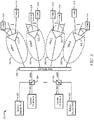
- FIG. 1 is a schematic diagram of an embodiment of a PON sub-network system 100 where embodiments of the present disclosure may operate.
- the PON sub-network system 100 may be an optical access network or part of an optical access network that comprises an OLT 110, a plurality of ONUs 120, and a plurality of ODNs A-D 130.
- the OLT 110 may be coupled to one or more ODNs 130 and each of the ODNs 130 may be coupled to a set of ONUs 120.
- the PON sub-network system 100 may be a communications network that does not comprise any active components to distribute data between the OLT 110 and the ONUs 120.
- the PON sub-network system 100 may use the passive optical components that include, but are not limited to isolators, circulators, filters, and unpowered splitters, in the ODN 130 (e.g. ODN A 130) to transport data between the OLT 110 and the ONUs 120.
- the PON sub-network system 100 may comprise one or more active components, such as optical amplifiers and/or power splitters.
- the PON sub-network system 100 may be implemented as a Next Generation Access (NGA) system, such as an XGPON, which may have a downstream bandwidth of about 10 Gb/s and an upstream bandwidth of at least about 2.5 Gb/s.
- NGA Next Generation Access
- the PON sub-network system 100 may be implemented as an EPON, a 10 Gigabit EPON, an APON, a BPON, a GPON, a WDM PON, a TDM PON, a TWDM PON, and/or combinations thereof.
- the OLT 110 may be any device, such as an OLT line card, that is configured to communicate with the ONUs 120 and external network (not shown). Specifically, the OLT 110 may act as an intermediary between the external network (e.g. a service provider network) and the ONUs 120. For instance, the OLT 110 may forward data received from the external network to the ONUs 120 and forward data received from the ONUs 120 onto the external network.
- the specific configuration of the OLT 110 may vary depending on the type of PON sub-network system 100, in an embodiment, the OLT 110 may comprise a transmitter and a receiver.
- the OLT 110 may comprise a converter that converts the network protocol into the PON protocol.
- the OLT 110 converter may also convert the PON protocol into the network protocol.
- the OLT 110 may be located at a central location, such as a central office, but may be located at other locations as well.
- the ODNs A-D 130 may be a data distribution system, which may comprise optical fiber cables, couplers, splitters, distributors, and/or other network devices.
- the optical fiber cables, couplers, splitters, distributors, and/or other equipment may be passive optical components.
- the optical fiber cables, couplers, splitters, distributors, and/or other network devices may be components that do not require any power to distribute data signals between the OLT 110 and the ONUs 120.
- ODNs A-D 130 may comprise one or a plurality of active components, such as optical amplifiers.
- the ODNs A-D 130 may extend from the OLT 110 to the ONUs 120 in a branching configuration as shown in FIG. 1 , but may be alternatively configured in any other point to multi-point configuration.
- ODNs A-D 130 may also be referenced as an optical access network and may be used interchangeably throughout this disclosure.
- the ONUs 120 may be any devices that are configured to communicate with the OLT 110 and a customer or user (not shown). Specifically, the ONUs 120 may act as an intermediary between the OLT 110 and the customer. For instance, the ONUs 120 may forward data received from the OLT 110 to the customer and forward data received from the customer onto the OLT 110.
- the ONUs 120 may comprise a tunable optical transmitter configured to send optical signals to the OLT 110 and a tunable optical receiver configured to select one of the downstream wavelength within an ODN 130 and receive optical signals in one downstream channel from the OLT 110.
- the transmitters for the ONUs 120 may comprise tunable lasers configured to tune to different wavelengths (e.g. ⁇ 1 - ⁇ 8 ). Additionally, the ONUs 120 may comprise a converter that converts the optical signal into electrical signals for the customer, such as signals in the Ethernet or asynchronous transfer mode (ATM) protocol, and a second transmitter and/or receiver that may send and/or receive the electrical signals to/from a customer device. In some embodiments, ONUs 120 and optical network terminals (ONTs) are similar, and thus the terms are used interchangeably throughout the disclosure. The ONUs 120 may be typically located at one or more distributed locations, such as the customer premises, but may also be located at other locations as well.
- ATM asynchronous transfer mode
- ONTs optical network terminals
- the PON sub-network system 100 may be arranged such that one or more ODNs 130 are coupled to the OLT 110.
- the OLT 110 may be coupled to a plurality of ODNs 130, where each of the ODNs 130 is coupled to a set of ONUs 120.
- a first set of ONUs 120 may be coupled to ODN A 130;
- a second set of ONUs 120 may be coupled to ODN B 130;
- a third set of ONUs 120 may be coupled to ODN C 130;
- a fourth set of ONUs 120 may be coupled to ODN D 130.
- Each ODN 130 (e.g. ODN A 130) may comprise a splitter (e.g.
- the OLT 110 may be configured such that OLT resources (e.g. tunable transmitters) may be dynamically allocated to reach any of the ODNs A-D 130. Allocating OLT resources amongst the ODNs A-D 130 within the PON sub-network system 100 will be discussed in more detail in below.
- OLT resources e.g. tunable transmitters
- upstream refers to the direction that the optical signals travel from an ONU 120 to an OLT 110.
- downstream refers to the direction that the optical signals travel from an OLT 110 to an ONU 120.
- channel and “wavelength band” may be used interchangeably throughout this disclosure and may refer to a wavelength or range of wavelengths used to encode, transmit, and/or receive data.
- a downstream channel and/or wavelength band may have a wavelength value of about 1596 nanometers (nm) with a tolerance of plus or minus 0.1 nm for a certain downstream channel.
- an upstream channel and/or wavelength band may have wavelength value of about 1524 nanometers (nm) with a tolerance of plus or minus 0.2nm to 0.3nm for a certain upstream channel.
- nm nanometers
- tunable transmitter may be interpreted throughout this disclosure to be a tunable laser without a modulator or a tunable laser with a modulator.
- FIG. 2 is a schematic diagram of an embodiment of a network element 200 within a PON sub-network.
- the network element 200 may be an OLT 110, as described in FIG. 1 , or a port within an OLT 110.
- the network element 200 may be suitable for implementing one or more embodiments of systems, methods, and schemes disclosed herein, such as method 1500.
- the network element 200 may be configured to transmit and/or receive optical signals that include, but are not limited to TWDM based transmissions over an optical fiber.
- the network element 200 may be implemented in a single node or the functionality of network element 200 may be implemented in a plurality of nodes.
- the term network element encompasses a broad range of devices of which network element 200 is merely an example.
- Network element 200 is included for purposes of clarity of discussion, but is in no way meant to limit the application of the present disclosure to a particular network element embodiment or class of network element embodiments. At least some of the features/methods described in the disclosure may be implemented in a network apparatus or component such as a network element 200. For instance, the features/methods in the disclosure may be implemented using hardware, firmware, and/or software installed to run on hardware.
- the network element 200 may comprise transceivers (Tx/Rx) 210, which may be transmitters, receivers, or combinations thereof.
- Tx/Rx 210 may be coupled to a plurality of PON ports 220 (e.g. downstream interfaces) for transmitting and/or receiving frames from ONUs within an optical access networks and a Tx/Rx 210 coupled to a plurality of external network ports 250 (e.g. upstream interfaces) for transmitting and/or receiving frames from nodes with an external network, such as a metro network or a service provider core network.
- a processor 230 may be coupled to the Tx/Rxs 210 to process the frames and/or determine which nodes to send frames to.
- the processor 230 may comprise one or more multi-core processors and/or memory devices 232, which may function as data stores, buffers, etc.
- Processor 230 may be implemented as a general processor or may be part of one or more application specific integrated circuits (ASICs), field programmable gate array (FPGA), and/or digital signal processors (DSPs).
- ASICs application specific integrated circuits
- FPGA field programmable gate array
- DSPs digital signal processors
- Processor 230 may comprise a reconfiguration module 234, which may implement the methods discussed herein, such as scheduling transmission of optical signals over one or more ODNs.
- the reconfiguration module 234 may determine the current traffic load for each of the ODNs and dynamically allocate a transmitter within a transmitter array to transmit the corresponding optical signal. In other words, the reconfiguration module 234 may select any of the transmitters and instruct the transmitter to be tuned to a specified wavelength in order to transmit optical signals over any one of the ODNs within a PON sub-network.
- the reconfiguration module 234 may be implemented within the network element 200 when the network element 200 is an OLT. In another alternative embodiment, the reconfiguration module 234 may be implemented on a separate network element 200 external to an OLT.
- the PON ports 220 and/or external network ports 250 may comprise electrical and/or optical transmitting and/or receiving components.
- a design that is still subject to frequent change may be preferred to be implemented in software, because re-spinning a hardware implementation is more expensive than re-spinning a software design.
- a design that is stable that will be produced in large volume may be preferred to be implemented in hardware, for example in an ASIC, because for large production runs the hardware implementation may be less expensive than the software implementation.
- a design may be developed and tested in a software form and later transformed, by well-known design rules, to an equivalent hardware implementation in an application specific integrated circuit that hardwires the instructions of the software. In the same manner as a machine controlled by a new ASIC is a particular machine or apparatus, likewise a computer that has been programmed and/or loaded with executable instructions may be viewed as a particular machine or apparatus.
- any processing of the present disclosure may be implemented by causing a processor (e.g., a general purpose central processing unit (CPU) inside a computer system) in a computer system (e.g., an OLT or an ONU) to execute a computer program.
- a computer program product can be provided to a computer or a mobile device using any type of non-transitory computer readable media.
- the computer program product may be stored in a non-transitory computer readable medium in the computer or the network device.
- Non-transitory computer readable media include any type of tangible storage media. Examples of non-transitory computer readable media include magnetic storage media (such as floppy disks, magnetic tapes, hard disk drives, etc.), optical magnetic storage media (e.g.
- the computer program product may also be provided to a computer or a network device using any type of transitory computer readable media. Examples of transitory computer readable media include electric signals, optical signals, and electromagnetic waves. Transitory computer readable media can provide the program to a computer via a wired communication line (e.g. electric wires, and optical fibers) or a wireless communication line.
- a wired communication line e.g. electric wires, and optical fibers
- FIG. 3 is a schematic diagram of an embodiment of a reconfigurable PON architecture for a PON sub-network 300.
- the PON sub-network 300 comprises a plurality of tunable transmitter arrays A-D 302, a plurality of multiple channel receivers 304, a 4x4 cyclic AWG wavelength router 308, a plurality of ODNs A-D 310, a plurality of splitters 312, and a plurality of tunable ONUs (T-ONU) 314.
- the tunable transmitter arrays A-D 302 may comprise a plurality of tunable transmitters (not shown in FIG. 3 ).
- the tunable transmitters may be configured to tune to a plurality of wavelengths that may be used to encode and transmit data.
- the transmitter arrays A-D 302 may be located within a single OLT or may be located in different OLTs. In one embodiment, when the data traffic for the PON sub-network 300 is relatively low, some of the OLT resources, such as the tunable transmitter arrays A-D 302 and/or tunable transmitters may be put into sleep mode to conserve power consumption.
- the multiple channel receivers 304 comprises a plurality of channel receivers that are each configured to receive an upstream encoded wavelength (e.g. wavelength ⁇ 1u ).
- the number of channel receivers within the multiple channel receivers 304 is the same as the maximum number of upstream wavelengths transmitted by the T-ONUs 314. For instance, if the tunable transmitters within T-ONUs 314 are configured to encode data using a maximum of eight different upstream wavelengths, then the multiple channel receivers 304 comprise eight different channel receivers.
- the plurality of channel receivers may be used to establish point to point connections for upstream transmission from the T-ONUs 314. Implementing point to point connections may be beneficial in backhaul type networks (e.g. wireless backhaul network) or immersive video tele-presenting applications (e.g. tele-dynamic show).
- the upstream encoded wavelengths received by each multiple channel receiver 304 may correspond to the wavelengths transmitted by the tunable transmitter array 302 for a given wavelength order.
- the multiple channel receiver 304 corresponding to tunable transmitter array A 302 may receive upstream data encoded using wavelengths ⁇ 1u, ⁇ 2u, and ⁇ 3u, which may come from one ODN 310 or multiple ODNs 310.
- the downstream wavelengths and the corresponding upstream wavelengths may not have the same wavelength value.
- downstream wavelength ⁇ 1d may have a wavelength range of 1596 nm to 1605 nm
- the upstream wavelength ⁇ 1u may have a wavelength range of 1524 nm to 1544 nm.
- labeling wavelengths ⁇ 1d, ⁇ 2d, and ⁇ 3d, and ⁇ 1u, ⁇ 2u, and ⁇ 3u represents the order of wavelength values from the shortest wavelength value to the longest wavelength.
- the wavelengths labeled ⁇ 1d and ⁇ 1u have the shortest wavelength in the downstream direction and upstream direction, respectively
- the wavelengths labeled ⁇ 3d and ⁇ 3u have the longest wavelength in the downstream direction and upstream direction, respectively.
- the T-ONU 310 if one downstream wavelength ⁇ 1d is received by one of the T-ONUs 310, the T-ONU 310 that received downstream wavelength ⁇ 1d can emit an upstream wavelength ⁇ 1u to reach the corresponding optical channel that emits downstream wavelength ⁇ 1d or the same port receiver of the 4x4 cyclic AWG wavelength router 308.
- labeling wavelengths such as ⁇ 1d and ⁇ 1u, represent the wavelengths the transceiver at the OLT emits and receives, respectively.
- An optical filter 306 such as a WDM filter, may be positioned in between the AWG wavelength router 308 and the transmitter arrays A-D 302/multiple channel receivers 304.
- the optical filters 306 may provide wavelength sensitive loss, isolation and/or return loss.
- the optical filters 306 may be in-line, wavelength selective, components that allow a specific range of wavelengths to pass through and/or reflect with low attenuation.
- the optical filters 306 may be used to separate out upstream optical signals from downstream optical signals such that upstream optical signals are reflected to the multiple channel receivers 304 and the downstream optical signals are passed through to the 4x4 cyclic AWG wavelength router 308.
- the optical filters 306 may be placed between the 4x4 cyclic AWG wavelength router 308 and the ODN networks 310.
- the optical filters 306 may reside in the OLT or ODNs 310.
- the tunable transmitter arrays A-D 302 and the multiple channel receivers 304 are coupled to 4x4 cyclic AWG wavelength router 308.
- the 4x4 cyclic AWG wavelength router 308 may comprise four input ports and four output ports.
- the 4x4 notation refers the number of input ports (e.g. 4 inputs) and the number of output ports (4 outputs) in a downstream direction.
- the input ports are coupled to the tunable transmitter arrays A-D 302 and each of the output ports are coupled to one of the ODNs A-D 310.
- one of the output ports for the 4x4 cyclic AWG wavelength router 308 is coupled to ODN A 310 and a separate output port is coupled to ODN B 310.
- the 4x4 cyclic AWG wavelength router 308 may be configured to route predefined wavelength bands with certain channel spacing received at an input port to a predetermined output port.
- the 4x4 cyclic AWG wavelength router 308 may be configured with a cyclic nature that output wavelengths in a repeating order (e.g. based on input ports) for each of the output ports.
- the 4x4 cyclic AWG wavelength router 308 may be a hybrid device that comprises a 4x4 AWG wavelength router and a 4x4 power splitter (not shown in FIG. 3 ) that may amplify downstream and upstream light functions.
- FIG. 3 illustrates the use of a 4x4 cyclic AWG wavelength router 308, other optical routing or switch devices, such as a multi-input port and multi-output port, free space, cyclic wavelength router or switching device, may be used route wavelengths received at an input to a designated output in repeating order.
- other optical routing or switch devices such as a multi-input port and multi-output port, free space, cyclic wavelength router or switching device, may be used route wavelengths received at an input to a designated output in repeating order.
- the 4x4 cyclic AWG wavelength router 308 may output the downstream optical signals allocated for the ODNs A-D 310 to reach the T-ONUs 314.
- ODNs A-D 310 and T-ONUs 314 may be substantially similar to ODNs 130 and ONUs 120 as described in FIG. 1 , respectively.
- each of the ODNs A-D 310 may comprise a splitter 312 that receives the downstream optical signal from the 4x4 cyclic AWG wavelength router 308.
- the splitter 312 may be a passive optical device that splits the downstream optical signal to a plurality of split optical signals and sends the split optical signals to different T-ONUs 314.
- Each of the splitters 312 may be configured as a 1:32, 1:64, 1:128, or any other splitter ratio and may split an incoming downstream optical signal based on the different wavelengths used to encode the incoming downstream optical signal.
- T-ONUs 314 may comprise tunable transmitters used to transmit optical signals in the upstream direction.
- the splitters 312 may merge the different upstream wavelengths received from T-ONUs 314 into a single upstream optical fiber and send the merged multi-wavelength upstream optical signal to the 4x4 cyclic AWG wavelength router 308.
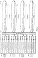
- FIG. 4 is a schematic diagram of an embodiment of a reconfigurable PON sub-network 400 with an eight wavelength tuning range.
- the reconfigurable PON sub-network 400 comprises a plurality of tunable transmitter arrays A-D 402, a 4x4 cyclic AWG wavelength router 308 and a plurality of ODNs A-D 310.
- Each of the tunable transmitter arrays A-D 402 comprises a plurality of tunable transmitters 404.
- each of the tunable transmitters 404 may be configured to tune to eight different wavelength bands.
- the tunable transmitters 404 may be able to encode and transmit data using eight different optical channels.
- the nominal channel space between two wavelength bands e.g.
- the actual channel space may be about 0.6 nm for a tolerance of about 0.1 nm or about 0.4 nm (about 50 GHz) for a tolerance of about 0.2 nm.
- each tunable transmitter arrays A-D 402 the tunable transmitters 404 may be coupled to an optical coupler 406 (e.g. MMI or star coupler).
- the optical coupler 406 combines the optical signals transmitted from each of the tunable transmitters 404 for a given tunable transmitter array 402 (e.g. tunable transmit array A 402) and outputs a combined optical signal that feeds into the 4x4 cyclic AWG wavelength router 308.
- the tunable transmitter arrays A-D 402, tunable transmitters 404, and optical coupler 406 will be discussed in more detail in FIG. 14 .
- FIG. 4 also illustrates the wavelength output arrangement of the 4x4 cyclic AWG wavelength router 308 over the different ODNs A-D 310.
- the 4x4 cyclic AWG wavelength router 308 may be configured with a cyclic nature that repeats orders and may allocate predefined wavelength bands received from the input ports to certain output ports.
- the 4x4 cyclic AWG wavelength router 308 routes wavelength bands ⁇ 1 - ⁇ 8 to different ODNs A-D 310 depending on the input of the 4x4 cyclic AWG wavelength router 308.
- Each of the inputs of the 4x4 cyclic AWG wavelength router 308 are coupled to different tunable transmitter arrays A-D 402. Using FIG.
- the eight different wavelength bands that may be outputted to ODN A 310 are labeled as ⁇ A1 , ⁇ B2 , ⁇ C3 , ⁇ D4 , ⁇ A5 , ⁇ B6 , ⁇ C7 , and ⁇ D8 .
- Label ⁇ A1 indicates that the 4x4 cyclic AWG wavelength router 308 has been configured such that wavelength band ⁇ 1 is emitted from tunable transmitter array A 402; label ⁇ B2 indicates that the wavelength band ⁇ 2 is emitted from tunable transmitter array B 402; label ⁇ C3 indicates that the wavelength band ⁇ 3 is emitted from tunable transmitter array C 402; and label ⁇ D4 indicates that the wavelength band ⁇ 4 is emitted from tunable transmitter array D 402.
- the label ⁇ A5 indicates that the 4x4 cyclic AWG wavelength router 308 has been configured to return to the input associated with tunable transmitter array A 402 to emit wavelength band ⁇ 5 for ODN A 310.
- the 4x4 cyclic AWG wavelength router 308 repeats the same order for ⁇ 2 , ⁇ 3 , and ⁇ 4 .
- labels ⁇ B6 , ⁇ C7 , and ⁇ D8 correspond to the 4x4 cyclic AWG wavelength router 308 routing inputs that correspond to the tunable transmitter array B 402, tunable transmitter array C 402, and tunable transmitter array D 402 to emit wavelength bands ⁇ 6 , ⁇ 7 , and ⁇ 8 , respectively. Similar label notation is used for the wavelength bands ⁇ 1 - ⁇ 8 that 4x4 cyclic AWG wavelength router 308 outputs to the other ODNs B-D 310.
- Each of the tunable transmitters 404 within each of the tunable transmitter arrays A-D 402 may access any of the ODNs A-D 310 by tuning the tunable transmitters 404 to encode data at a certain wavelength band. For example, for a tunable transmitter 404 within tunable transmitter array A 402 (e.g. top most tunable transmitter 404) to access ODN A 310, the tunable transmitter 404 may be tuned to wavelength bands ⁇ 1 or ⁇ 5 .
- the tunable transmitter 404 may be tuned to wavelength bands ⁇ 2 or ⁇ 6 ; to access ODN C 310, the tunable transmitter 404 may be tuned to wavelength bands ⁇ 3 or ⁇ 7 ; and to access ODN D 310, the tunable transmitter 404 may be tuned to wavelength bands ⁇ 4 or ⁇ 8 .
- Other tunable transmitters 404 within other tunable transmitter arrays B-D 402 may be tuned to other wavelength bands in order to access the same ODNs A-D 310 as shown in FIG. 4 .
- Persons of ordinary skill in the art are aware that other combination of wavelength sequences may be output to the ODNs A-D 310 and that the disclosure is not limited to only the specific applications in the FIG. 4 other figures (e.g. FIGS. 5-13 ).
- the use and discussion in FIG. 4 and other figures (e.g. FIGS. 5-13 ) are only an example to facilitate ease of description and explanation.
- the OLT may dynamically increase or decrease the data rate capacity (e.g. bandwidth) for each of the ODNs A-D 310 by adjusting the number of wavelengths allocated to encode and transmit data for each of the ODNs A-D 310.
- the OLT may initially allocate transmission of four downstream wavelengths on each ODNs A-D 310 simultaneously using the 16 different tunable transmitters.
- the OLT may dynamically adjust the number of downstream wavelengths assigned to each ODNs A-D 310 by re-tuning one or more of the tunable laser transmitters 404 in one or more tunable transmitter arrays A-D 402.
- the OLT may dynamically allocate wavelengths for the tunable transmitter arrays A-D 402 to transmit within one ODN.
- FIG. 5 is a schematic diagram of another embodiment of a reconfigurable PON sub-network 500 with an eight wavelength tuning range.
- FIG. 5 illustrates an example case of allocating OLT resource for downstream transmission of wavelengths over different ODNs A-D 310 using 16 different tunable transmitters 404.
- each of the tunable transmitter arrays A-D 402 comprise four different tunable transmitters.
- the four tunable transmitters 404 within tunable transmitter array A 402 may be tuned to wavelength bands ⁇ 1 , ⁇ 5 , ⁇ 2 , and ⁇ 4 ; the four tunable transmitters 404 within tunable transmitter array B 402 may be tuned to wavelength bands ⁇ 1 , ⁇ 2 , ⁇ 6 , and ⁇ 4 ; the four tunable transmitters 404 within tunable transmitter array C 402 may be tuned to wavelength bands ⁇ 1 , ⁇ 2 , ⁇ 3 , and ⁇ 7 ; and the four tunable transmitters 404 within tunable transmitter array D 402 may be tuned to wavelength bands ⁇ 8 , ⁇ 2 , ⁇ 3 , and ⁇ 4 .
- the 16 different tunable transmitters 404 encode data using the wavelength bands to access different ODNs A-D 310.
- two tunable transmitters 404 within each of the tunable transmitter arrays A-D 402 are used to transmit wavelengths labeled ⁇ A1 , ⁇ B2 , ⁇ C3 , ⁇ D4 , ⁇ A5 , ⁇ B6 , ⁇ C7 , and ⁇ k D8 for ODN A 310.
- two tunable transmitters 404 within tunable transmitter array A 402 emit the wavelengths labeled ⁇ A1 and ⁇ A5 ;
- two tunable transmitters 404 within tunable transmitter array B 402 emit the wavelengths labeled ⁇ B2 and ⁇ B6 ;
- two tunable transmitters 404 within tunable transmitter array C 402 emit the wavelengths labeled ⁇ C3 and ⁇ C7 ;
- two tunable transmitters 404 within tunable transmitter array D 402 emit the wavelengths labeled ⁇ D4 and ⁇ D8 .
- a tunable transmitter 404 within tunable transmitter array A 402 emits the wavelength labeled ⁇ A2 ; for ODN C 310, a tunable transmitter 404 within tunable transmitter array B 402, tunable transmitter array C 402, and tunable transmitter array D 402 emit the wavelengths labeled ⁇ B4 , ⁇ C1 , and ⁇ D2 , respectively; and for ODN D 310, a tunable transmitter 404 within tunable transmitter array A 402, tunable transmitter array B 402, tunable transmitter array C 402, and tunable transmitter array D 402 emit the wavelengths labeled ⁇ A4 , ⁇ B1 , ⁇ C2 , and ⁇ D3 , respectively.
- each of the wavelength bands (e.g. ⁇ A1 ) represents about a 10 Gb/s optical channel
- the transmission of wavelength bands ⁇ A1 , ⁇ B2 , ⁇ C3 , ⁇ D4 , ⁇ A5 , ⁇ B6 , ⁇ C7 , and ⁇ D8 over ODN A 310 may represent a data rate of about 80 Gb/s allocated to ODN A 310.
- ODN B 310, ODN C 310, and ODN D 310 may be allocated with a data rate of 10 Gb/s, 30 Gb/s, and 40 Gb/s, respectively.
- the number of wavelength bands allocated for each of the ODNs A-D 310 may be dependent on traffic load and other network conditions for the ODNs A-D 310.
- the OLT that houses tunable transmitter arrays A-D 402 may determine that ODN A 310 may be associated with a large enterprise network that may require a substantial amount of OLT resources during a certain time period (e.g. during a work day), and ODN B 310 may be associated with residential networks that may require relatively less OLT resources during the same time period.
- the OLT may allocate more OLT resources (e.g. tunable transmitters 404) to the large enterprise network by tuning eight of the 16 tunable transmitters 404 to wavelength bands allocated for ODN A 310 for the certain time period.
- the OLT resources may subsequently be reconfigured or reallocated to dynamically provide a more efficient, scalable, flexible, and reconfigurable PON network. For instance, after the certain time period expires (e.g. during a weekend), the OLT resources may be reconfigured such that relatively less OLT resources are allocated to ODN A 310 and relatively more OLT resources are allocated to ODN B 310.
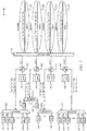
- FIG. 6 is a schematic diagram of an embodiment of a reconfigurable PON sub-network 600 with an eight wavelength tuning range and comprises a plurality of multiple channel receivers to receive upstream wavelengths from a plurality of ONUs.
- the reconfigurable PON sub-network 600 is substantially similar to the reconfigurable PON sub-network 400 in FIG. 4 except that the reconfigurable PON sub-network 600 further comprises a plurality of multiple channel receivers and a plurality of optical filters 306 that route upstream optical signals to the multiple channel receivers prior to reaching the 4x4 cyclic AWG wavelength router 308.
- Each of the multiple channel receivers comprises a 1x8 demultiplexer 602 and a plurality of channel receivers Rx1-Rx8 604.
- Each of the 1x8 demultiplexers 602 may be an active or a passive demultiplexer that receives an upstream optical signal within one of the ODNs A-D 310 and separates out the different wavelength bands within the optical signal and sends the wavelength bands to the corresponding channel receivers 604.
- Each of the upstream wavelength bands received at the 1x8 demultiplexers 602 may be from tunable ONU transmitters associated with each of the ODNs A-D 310.
- the number of output channels in the upstream direction for the 1x8 demultiplexers 602 may be the same as the number of maximum upstream wavelengths tunable by the ONUs.
- the multiple channel receiver that is coupled to ODN A 310 may receive an upstream optical signal that comprises wavelength bands ⁇ AU1 , ⁇ AU2 , ⁇ AU3 , ⁇ AU4 , ⁇ AU5 , ⁇ AU 6, ⁇ AU7 , and ⁇ AU8 that are transmitted from ONUs coupled to ODN A 310;
- the multiple channel receiver that is coupled to ODN B 310 may receive an upstream optical signal that comprises wavelength bands ⁇ BU1 , ⁇ BU2 , ⁇ BU3 , ⁇ BU4 , ⁇ BU5 , ⁇ BU6 , ⁇ BU7 , and ⁇ BU8 that are transmitted from ONUs coupled to ODN B 310;
- the multiple channel receiver that is coupled to ODN C 310 may receive an upstream optical signal that comprises wavelength bands ⁇ CU1 , ⁇ CU2 , ⁇ CU3 , ⁇ CU4 , ⁇ CU5 , ⁇ CU6
- the labels ⁇ AU1 - ⁇ AU8 , ⁇ BU1 - ⁇ BU8 , ⁇ CU1 - ⁇ CU8 , and ⁇ DU1 - ⁇ DU8 represent the different upstream wavelength bands ⁇ 1 - ⁇ 8 received from the different ODNs A-D 310.
- the different upstream wavelength bands for each ODN A-D 310 in FIG. 6 represents that any ONU or user may tune its upstream tunable transmitter to any one of the upstream wavelengths bands ⁇ 1 - ⁇ 8 .
- the number of channel receivers 604 for each ODN A-D 310 may correspond to the maximum number of wavelengths bands the ONUs are able to tune to. In FIG.
- each of the channel receivers Rx1, Rx2, Rx3, Rx4, Rx5, Rx6, Rx7, Rx8 604 may be designated to receive the data encoded in one of the upstream wavelength bands ⁇ 1 , ⁇ 2 , ⁇ 3 , ⁇ 4 , ⁇ 5 , ⁇ 6 , ⁇ 7 , and ⁇ 8 , respectively.
- the ONUs may be able to implement point to multi-point connections and point to point connections simultaneously, which may be beneficial in backhaul type networks (e.g. wireless backhaul) or immersive video tele-presenting applications (e.g. tele-dynamic show).
- backhaul type networks e.g. wireless backhaul
- immersive video tele-presenting applications e.g. tele-dynamic show
- FIG. 6 uses case example, there are 16 tunable transmitters and 32 channel receivers at OLT side, where 16 of the 32 channel receivers may be used for point to point connections.
- FIG. 6 illustrates that each of the ODNs A-D 310 are able to transport eight upstream wavelengths to the OLT, the actual number of upstream wavelength transmitted for each of the ODNs A-D 310 may have a range of about four for symmetrical downstream and upstream TWDM-PON architecture.
- FIG. 7 is a schematic diagram of another embodiment of a reconfigurable PON sub-network 700 with an eight wavelength tuning range and comprises a plurality of multiple channel receivers to receive upstream wavelengths from a plurality of ONUs.
- the reconfigurable PON sub-network 700 is substantially similar to the reconfigurable PON sub-network 600 in FIG. 6 except that the optical filters 306 are positioned between the tunable transmitter array 402 and the 4x4 cyclic AWG wavelength router 308. Each optical filter 306 routes the upstream wavelength bands to the 1x8 demultiplexer 602 after the upstream wavelengths pass through the 4x4 cyclic AWG wavelength router 308.
- the 4x4 cyclic AWG wavelength router 308 may be configured such that upstream wavelengths ⁇ 1 - ⁇ 8 received by the ODNs A-D 310 in the upstream direction is output to different 4x4 cyclic AWG wavelength router 308 ports 1-4 based on a repeating and predetermined order. As shown in FIG. 7 , the upstream optical signal received from port 1 of the 4x4 cyclic AWG wavelength router 308 may comprise upstream wavelengths ⁇ A1 , ⁇ B2 , ⁇ C3 , ⁇ D4 , ⁇ A5 , ⁇ B6 , ⁇ C7 , and ⁇ D8 .
- Labels ⁇ A1 and ⁇ A5 may represent that wavelengths ⁇ 1 and ⁇ 5 are from ODN A 310; labels ⁇ B2 and ⁇ B6 may represent that wavelengths ⁇ 2 and ⁇ 6 are from ODN B 310; labels ⁇ C3 and ⁇ C7 may represent that wavelengths ⁇ 3 and ⁇ 7 are from ODN C 310; and labels ⁇ D4 and ⁇ D8 may represent that wavelengths ⁇ 4 and ⁇ 8 are from ODN D 310.
- Wavelengths received at ports 2-4 of the 4x4 cyclic AWG wavelength router 308 may be labeled in a similar notation as described for port 1.
- the upstream wavelengths received at ports 1-4 of the 4x4 cyclic AWG wavelength router 308 may then be inputted into the optical filters 306.
- the optical filters 306 may send the upstream wavelengths to the 1x8 demultiplexer 602 which separates out and sends the corresponding wavelengths to the channel receivers Rx1-Rx8 604.
- FIG. 1x8 demultiplexer 602 which separates out and sends the corresponding wavelengths to the channel receivers Rx1-Rx8 604.
- channel receivers Rx1, Rx2, Rx3, Rx4, Rx5, Rx6, Rx7, and Rx8 604 that are coupled to port 1 of the 4x4 cyclic AWG wavelength router 308 may receive ⁇ A1 , ⁇ B2 , ⁇ C3 , ⁇ D4 , ⁇ A5 , ⁇ B6 , ⁇ C7 , and ⁇ D8 , respectively, after passing through the 1x8 demultiplexer 602.
- the other channel receivers Rx1-Rx8 604 that are coupled to ports 2-4 of the 4x4 cyclic AWG wavelength router 308 may be designated to receive certain wavelengths from different ODNs A-D 310 similar to channel receivers Rx1-Rx8 604 that are coupled to port 1 of the 4x4 cyclic AWG wavelength router 308. Similar to FIG. 6 , the number of channel receivers in each multiple channel receiver and the number of outputs channels for the 1x8 demultiplexer 602 may be the same number as the maximum number upstream wavelengths transmitted by the ONUs.
- FIG. 8 is a schematic diagram of another embodiment of a reconfigurable PON sub-network 800 with an eight wavelength tuning range and comprises a plurality of multiple channel receivers to receive upstream wavelengths from a plurality of ONUs.
- FIG. 8 illustrates an example case of receiving upstream transmission from the different ODNs A-D 310.
- the allocation of OLT resources e.g. tunable transmitter arrays 402 and tunable transmitters 404 for downstream transmission may be substantially similar to FIG. 5 .
- the OLT has allocated eight downstream wavelengths to ODN A 310, one downstream wavelength to ODN B 310, three downstream wavelengths to ODN C 310, and four downstream wavelengths to ODN D 310.
- the number of upstream wavelength allocated to each ODN A-D 310 may be adjusted (e.g. increased or decreased) to match the number of downstream wavelengths allocated for downstream transmission.
- the downstream and upstream wavelengths may correspond to each other such that that both the downstream and upstream wavelengths traverse through the same ports of 4x4 cyclic AWG wavelength router 308.
- the ONUs transmit upstream wavelengths ⁇ A1u , ⁇ B2u , ⁇ C3u , ⁇ D4u , ⁇ A5u , ⁇ B6u , ⁇ C7u , and ⁇ D8u , which correspond with the downstream wavelengths ⁇ A1d , ⁇ B2d , ⁇ C3d , ⁇ D4d , ⁇ A5d , ⁇ B6d , ⁇ C7d , and ⁇ D8d .
- the channel receivers 604 receive upstream wavelengths that correspond to the wavelengths that the tunable transmitter arrays A-D 402 provided in the downstream direction.
- the 1x8 demultiplexer 602 that is coupled to the tunable transmitter array A 402 may receive wavelengths labeled ⁇ A1u , ⁇ A5u , ⁇ A2u , and ⁇ A4u , which correspond with ⁇ A1d , ⁇ A5d , ⁇ A2d , and ⁇ A4d , respectively;
- the 1x8 demultiplexer 602 that is coupled to the tunable transmitter array B 402 may receive wavelengths labeled ⁇ B1u , ⁇ B2u , ⁇ B6u , and ⁇ B4u , which correspond with ⁇ B1d , ⁇ B2d , ⁇ B6d , and ⁇ B4d , respectively;
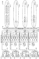
- FIG. 9 is a schematic diagram of an embodiment of a reconfigurable PON sub-network 900 with a 16 wavelength tuning range.
- the reconfigurable PON sub-network 900 comprises a plurality of tunable transmitter arrays A-D 902, a 4x4 cyclic AWG wavelength router 308 and a plurality of ODNs A-D 310.
- Each of the tunable transmitter arrays A-D 902 comprises a plurality of tunable transmitters 904 that are configured to tune to 16 different wavelength bands, which are denoted as ⁇ 1 - ⁇ 16 .
- the tunable transmitters 904 may be coupled to an optical coupler 906 (e.g. MMI or star coupler).
- an optical coupler 906 e.g. MMI or star coupler
- the optical coupler 906 combines the optical signals transmitted from each of the tunable transmitters 904 for a given tunable transmitter array 902 (e.g. tunable transmit array A 902) and outputs a combined optical signal that feeds into the 4x4 cyclic AWG wavelength router 308.
- the tunable transmitter arrays A-D 902, tunable transmitters 904, and optical coupler 906 will be discussed in more detail in FIG. 14 .
- FIG. 9 illustrates four tunable transmitters 904 within each tunable transmitter array 902, in other embodiments, the number of tunable transmitters 904 may range from more than 4 to 8 tunable transmitters 904.
- FIG. 9 illustrates the wavelength output arrangement of the 4x4 cyclic AWG wavelength router 308 over the different ODNs A-D 310.
- the 4x4 cyclic AWG wavelength router 308 assigns different tunable transmitter arrays A-D 902 to output the different wavelength bands ⁇ 1 - ⁇ 16 over different ODNs A-D 310.
- FIG. 9 illustrates the wavelength output arrangement of the 4x4 cyclic AWG wavelength router 308 over the different ODNs A-D 310.
- the 16 different wavelength bands that may be output to ODN A 310 are labeled as ⁇ A1 , ⁇ B2 , ⁇ C3 , ⁇ D4 , ⁇ A5 , ⁇ B6 , ⁇ C7 , ⁇ D8 , ⁇ A9 , ⁇ B10 , ⁇ C11 , ⁇ D12 , ⁇ A13 , ⁇ B14 , ⁇ C15 , and ⁇ D16 .
- Label ⁇ A1 indicates that the 4x4 cyclic AWG wavelength router 308 has been configured such that wavelength band ⁇ 1 is emitted from tunable transmitter array A 902; label ⁇ B2 indicates that the wavelength band ⁇ 2 is emitted from tunable transmitter array B 902; label ⁇ C3 indicates that the wavelength band ⁇ 3 is emitted from tunable transmitter array C 902; and label ⁇ D4 indicates that the wavelength band ⁇ 4 is emitted from tunable transmitter array D 902.
- the labels ⁇ A5, ⁇ A9, and ⁇ A13 indicate that the 4x4 cyclic AWG wavelength router 308 has been setup to repeat the tunable transmitter array 902 input order and assigns tunable transmitter array A 902 to emit wavelength bands ⁇ 5, ⁇ 9 , and ⁇ 13 , respectively.
- the remaining wavelength bands ⁇ 86, ⁇ B10 , and ⁇ B14 , ⁇ C7 ⁇ C11 , and ⁇ C14 , and ⁇ D8 , ⁇ D12 , and ⁇ D16 may correspond to tunable transmitter array B 902, tunable transmitter array C 902, and tunable transmitter array D 902, respectively. Similar notation is used for the wavelength bands ⁇ 1 - ⁇ 16 emitted on the other ODNs B-D 310.
- FIG. 10 is a schematic diagram of another embodiment of a reconfigurable PON sub-network 1000 with a 16 wavelength tuning range. Similar to FIG. 5 , FIG. 10 illustrates a use case example of transmitting wavelengths over different ODNs A-D 310 using a total of 16 different tunable transmitters 904 that are configured to tune to 16 different wavelength bands ⁇ 1 - ⁇ 16 . In FIG. 10 , each of the tunable transmitter arrays A-D 902 comprise four different tunable transmitters.
- the four tunable transmitters 904 within tunable transmitter array A 902 may be tuned to wavelength bands ⁇ 1 , ⁇ 5 , ⁇ 9 , and ⁇ 13 ; the four tunable transmitters 904 within tunable transmitter array B 902 may be tuned to wavelength bands ⁇ 7 , ⁇ 11 , ⁇ 3 , and ⁇ 5 ; the four tunable transmitters 904 within tunable transmitter array C 902 may be tuned to wavelength bands ⁇ 4 , ⁇ 8 , ⁇ 12 , and ⁇ 16 ; and the four tunable transmitters 904 within tunable transmitter array D 902 may be tuned to wavelength bands ⁇ 1 , ⁇ 5 , ⁇ 9 , and ⁇ 13 .
- the 16 different tunable transmitters 904 may access different ODNs A-D 310 by encoding data using different wavelength bands.
- no wavelengths are transmitted downstream over ODNs C and D 310 because the ONUs for the ODNs C and D 310 do not have any data request. Instead, wavelength resources have been moved to ODN A and B 310.
- all four of the tunable transmitters 904 within the tunable transmitter array A 902 are used to transmit wavelengths ⁇ A1 , ⁇ A5 , ⁇ A9 , and ⁇ A13 for ODN A 310.
- the 12 remaining tunable transmitters 904 in tunable transmitter arrays B-D 902 are tuned to wavelength bands that are allocated to ODN B 310. As shown in FIG.
- wavelengths ⁇ B3 , ⁇ C4 , ⁇ D1 , ⁇ B7 , ⁇ C8 , ⁇ D5 , ⁇ B11 , ⁇ C12 , ⁇ D9 , ⁇ B15 , ⁇ C16 , and ⁇ D13 are transmitted over ODN B 310.
- the OLT may dynamically allocate OLT resources depending on the network conditions and traffic loads over the ODNs A-D 310.
- FIG. 11 is a schematic diagram of an embodiment of a reconfigurable PON sub-network 1100 with a 16 wavelength tuning range and comprises a plurality of multiple channel receivers to receive upstream wavelengths from a plurality of ONUs.
- the reconfigurable PON sub-network 1100 is substantially similar to the reconfigurable PON sub-network 600 in FIG. 6 except that each of the multiple channel receivers comprises sixteen channel receivers Rx1-Rx16 1104 and a 1x16 demultiplexer 1102.
- FIG. 11 illustrates that the reconfigurable PON sub-network 1100 may comprise a total of 64 channel receivers 1104 and four 1x16 demultiplexers.
- Each of the 1x16 demultiplexers 1102 may be an active or a passive demultiplexer that receives an upstream optical signal within one of the ODNs A-D 310 and separates out the different wavelength bands within the optical signal and sends the wavelength bands to the corresponding channel receivers 604.
- Each of the upstream wavelength bands received at the 1x16 demultiplexers 602 may be from tunable ONU transmitters associated with each of the ODNs A-D 310.
- the multiple channel receiver that is coupled to ODN A 310 may receive an upstream optical signal that comprises wavelength bands ⁇ Au1 , ⁇ Au2 , ⁇ Au3 , ⁇ Au4 ... ⁇ Au13 , ⁇ Au14 , ⁇ Au15 , and ⁇ Au16 transmitted from ONUs coupled to ODN A 310;
- the multiple channel receiver that is coupled to ODN B 310 may receive an upstream optical signal that comprises wavelength bands ⁇ Bu1 , ⁇ Bu2 , ⁇ Bu3 , ⁇ Bu4 ... ⁇ Bu13 , ⁇ Bu14 , ⁇ Bu15 , and ⁇ Bu16 transmitted from ONUs coupled to ODN B 310;
- the multiple channel receiver that is coupled to ODN C 310 may receive an upstream optical signal that comprises wavelength bands ⁇ Cu1 , ⁇ Cu2 , ⁇ Cu3 , ⁇ Cu4 ... ⁇ Cu13 , ⁇ Cu14 , ⁇ Cu15 , and ⁇ Cu16 transmitted from ONUs coupled to ODN C 310;
- the different upstream wavelength bands for each ODN A-D 310 in FIG. 11 represents that any ONU or user may tune its upstream tunable transmitter to any one of the upstream wavelengths bands ⁇ 1 , ⁇ 2 , ⁇ 3 , ⁇ 4 ... ⁇ 13 , ⁇ 14 , ⁇ 15 , and ⁇ 16 .
- Similar embodiments of the reconfigurable PON sub-networks 700 and 800 may also be applied to receiving 16 different upstream wavelength bands.
- the optical filters 306 may be moved such that the optical filters 306 are positioned between the tunable transmitter array 902 and the 4x4 cyclic AWG wavelength router 308. Similar to FIG. 7 , in this instance, the upstream optical signal received by the 1x16 demultiplexer that corresponds to the tunable transmitter array A 902 may comprise upstream wavelengths ⁇ Au1 , ⁇ Bu2 , ⁇ Cu3 , ⁇ Du4 ... ⁇ Au13 , ⁇ Bu14 , ⁇ Cu15 , and ⁇ Du16 ; the upstream optical signal received by the 1x16 demultiplexer that corresponds to the tunable transmitter array B 902 may comprise upstream wavelengths ⁇ Au2 , ⁇ Bu3 , ⁇ Cu4 , ⁇ Du1 ... ⁇ Au14 , ⁇ Bu15 , ⁇ Cu16 , and ⁇ Du13 ; the upstream optical signal received by the 1x16 demultiplexer that corresponds to the tunable transmitter array C 902 may comprise upstream wavelengths
- the reconfigurable PON sub-network 1100 may comprise a total of 32 tunable transmitters and 64 channel receivers 1004, which may make the PON sub-network 1100 more flexible for ever-growth application.
- FIG. 12 is a schematic diagram of an embodiment of a generalized reconfigurable PON sub-network 1200 with a wavelength tuning range of NxN wavelengths in the downstream direction.
- the reconfigurable PON sub-network 1200 may comprise N tunable transmitter arrays 1202.
- Each of the transmitter arrays A-N 1202 comprises K different tunable transmitters 1204 (e.g. 8 tunable transmitters 1204).
- the K different tunable transmitters 1204 may be coupled to an optical coupler 1206 that combines the different wavelengths from the tunable transmitters 1204 to output a single optical signal that is fed into an NxN cyclic AWG wavelength router 1208.
- Each of the tunable transmitters 1204 may be configured with a tuning range that is equal to or less than NxN.
- the NxN cyclic AWG wavelength router 1208 may have N downstream inputs from the tunable transmitter arrays 1202 and N output s for the N different ODNs 310. Similar to FIG. 6 and 9 , each of the tunable transmitters 1204 may access any of the ODNs A-N 310.
- the generalized reconfigurable PON sub-network 1200 may allocate the tunable transmitters 1204 to other ODNs 310.
- the OLT may dynamically increase or decrease one or more of the ODNs' 310 data rate.
- FIG. 13 is a schematic diagram of another embodiment of a generalized reconfigurable PON sub-network 1300 with a wavelength tuning range of NxN wavelengths in the downstream direction and upstream direction.
- PON sub-network 1300 may be substantially similar to PON sub-network 1200 except that the PON sub-network 1300 may further comprise a plurality of multiple channel receivers.
- Each of the multiple channel receivers may comprise a 1xM demultiplexer 1302 and M number of channel receivers 1304 and receive the upstream optical signals from the optical filters 306.
- Each of the 1xM demultiplexers 1302 may be an active or a passive demultiplexer that receives an upstream optical signal within one of the ODNs A-N 310 and separates out the different wavelength bands within the optical signal and sends the wavelength bands to the corresponding channel receivers 1304.
- Each of the upstream wavelength bands received at the 1xM demultiplexers 1302 may be from tunable ONU transmitters associated with each of the ODNs A-N 310.
- M represents the number of upstream wavelengths that the ONU transmitters are able to tune.
- the multiple channel receiver that is coupled to ODN A 310 may receive an upstream optical signal that comprises wavelength bands ⁇ AU1 , ⁇ AU2 , ⁇ AU3 , ⁇ AU4 ... ⁇ AU(M-3) , ⁇ AU(M-2) , ⁇ AU(M-1) , and ⁇ AUM transmitted from ONUs coupled to ODN A 310;
- the multiple channel receiver that is coupled to ODN B 310 may receive an upstream optical signal that comprises wavelength bands ⁇ Bu1 , ⁇ BU2 , ⁇ BU3 , ⁇ BU4 ... ⁇ BU(M-3) , ⁇ BU(M-2) , ⁇ BU(M-1) , and ⁇ BUM transmitted from ONUs coupled to ODN B 310;
- the multiple channel receiver that is coupled to ODN N 310 may receive an upstream optical signal that comprises wavelength bands ⁇ NU1 , ⁇ NU2 , ⁇ NU3 , ⁇ NU4 ... ⁇ NU(
- ODN A 310 may transport wavelengths ⁇ AD1 , ⁇ AD2 , ⁇ AD3 , ⁇ AD4 ... ⁇ AD(NxN-3) , ⁇ AD(NxN-2) , ⁇ AD(NxN-1) , and ⁇ ADNxN ;
- ODN B 310 may transport wavelengths ⁇ BD1 , ⁇ BD2 , ⁇ BD3 , ⁇ BD4 ... ⁇ BD(NxN-3) , ⁇ BD(NxN-2) , M BD(NxN-1) , and ⁇ BDNxN ;
- ODN N 310 may transport wavelengths ⁇ ND1 , ⁇ ND2 , ⁇ ND3 , ⁇ ND4 ... ⁇ ND(NxN-3) , ⁇ ND(NxN-2) , ⁇ ND(NxN-1) , and ⁇ NDNxN .
- FIG. 14 is a schematic diagram of an embodiment of a tunable transmitter array 1400.
- the tunable transmitter array 1400 that comprises a plurality of tunable laser with modulators A-M 1402, an optical coupler 1404.
- the tunable laser with modulator A-M 1402 may be configured to perform external modulation.
- the tunable transmitter array 1400 may comprise tunable lasers without a modulator that is configured to perform direct modulation.
- the type of modulation implemented may depend on the downstream data rate. For example, if the data rate for a wavelength band is about 2.5 Gb/s, the tunable transmitter may be a laser without a modulator that performs direct modulation.
- the tunable laser with modulator 1402 may be configured to perform external modulation. If the tunable laser with modulator 1402 is configured to perform external modulation, then the external modulator may be monolithically integrated with the tunable laser, such as electroabsorption modulator or Mach-Zehnder modulator. In another embodiment, the external modulator may not be integrated and located on a separate device.
- the optical coupler 1404 may be integrated or external to the tunable lasers with modulators 1402.
- the optical coupler 1404 may receive M different inputs from M different tunable lasers with modulators 1402 and output a combined optical signal based on the M different inputs into one fiber or waveguide.
- the combined optical signal may then sent to the one of the input ports of a cyclic AWG wavelength router.
- M may be represented as an integer and may represent the number of tunable transmitters within a tunable transmitter array 1400. As shown in FIGS. 4 , 5 , 9 , and 10 , M may have a value of about four. In other embodiments, the M value may be more than four (e.g. eight).
- the optical coupler 1404 may be an optical device, such as an MMI or star coupler that are not wavelength sensitive.
- the optic coupler 1404 may not be configured as a wavelength transmission selection device and may combine all input wavelength light into the optical coupler's 1404 output port.
- the optical coupler 1404 may not filter any of the wavelengths or otherwise limit the wavelengths that pass through to the output port.
- FIG. 15 is a flowchart of an embodiment of a method 1500 that dynamically allocates OLT resources over a plurality of ODNs.
- Method 1500 may be implemented within an OLT or some other similar device within a PON network.
- Method 1500 may start at step 1502 and determine the traffic load for each of the ODNs within a sub-network. After determining the traffic load, method 1500 may move to step 1504 and allocate OLT resources dynamically depending on the traffic load for each of the ODNs. Recall that the OLT may tune the tunable transmitters within a tunable transmitter array to different wavelengths when allocating the OLT resources to the ODNs. Afterwards, method 1500 may move to step 1506 and transmit downstream optical signals over the ODNs using the allocated OLT resources.
- Method 1500 may proceed to step 1508 to receive upstream optical signals for every ODN.
- Method 1500 may implement step 1508 before, in parallel, and/or after steps 1502, 1504, and 1506.
- Method 1500 may implement step 1508 using point to point connections between channel receivers in the OLT and the ONUs. The point to point connections may be implemented simultaneously with point to multi-point connections.
- R R l + k * (R u - R l ), wherein k is a variable ranging from 1 percent to 100 percent with a 1 percent increment, i.e., k is 1 percent, 2 percent, 3 percent, 4 percent, 5 percent, ..., 50 percent, 51 percent, 52 percent, ..., 95 percent, 96 percent, 97 percent, 98 percent, 99 percent, or 100 percent.
- any numerical range defined by two R numbers as defined in the above is also specifically disclosed.
Landscapes
- Engineering & Computer Science (AREA)
- Computer Networks & Wireless Communication (AREA)
- Signal Processing (AREA)
- Optical Communication System (AREA)
Claims (14)
- "Optical Line Terminal", OLT, das umfasst:ein erstes Abstimmbare-Sender-Array, das einen ersten abstimmbaren Sender und einen zweiten abstimmbaren Sender umfasst;einen Zyklisches-"Array-Waveguide-Grating"-, AWG-, Wellenlängenrouter, der mit dem ersten Abstimmbare-Sender-Array gekoppelt ist; undeine Vielzahl von Mehrkanalempfängern, die mit dem Zyklisches-AWG-Wellenlängenrouter gekoppelt sind;wobei jeder der Vielzahl von Mehrkanalempfängern eine Vielzahl von Kanalempfängern umfasst, von denen jeder so ausgeführt ist, dass er eine vorgeschaltete kodierte Wellenlänge empfängt, wobei die Anzahl von Kanalempfängern in jedem der Vielzahl von Mehrkanalempfängern die gleiche ist wie die maximale Anzahl von gesendeten vorgeschalteten Wellenlängen;wobei der Zyklisches-AWG-Wellenlängenrouter eine Vielzahl von Eingangsports und eine Vielzahl von Ausgangsports umfasst,wobei der Zyklisches-AWG-Wellenlängenrouter so ausgeführt ist, dass er:ein erstes optisches Signal empfängt, das von einem ersten abstimmbaren Sender über einen ersten Eingangsport der Vielzahl von Eingangsports emittiert wird;ein zweites optisches Signal empfängt, das von einem zweiten abstimmbaren Sender über einen ersten Eingangsport der Vielzahl von Eingangsports emittiert wird; unddas erste optische Signal und das zweite optische Signal zu den Ausgangsports leitet in Abhängigkeit von einer oder mehreren Wellenlängen, die zum Kodieren des ersten optischen Signals und des zweiten optischen Signals verwendet werden, undwobei die Ausgangsports mit einer Vielzahl von optischen Verteilungsnetzen, ODNs, gekoppelt sind.
- OLT nach Anspruch 1, wobei der Zyklisches-AWG-Wellenlängenrouter ferner so ausgeführt ist, dass er eine Vielzahl von optischen Signalen, die von dem ersten abstimmbaren Laser emittiert werden, zu einem der Ausgangsports, die mit den ODNs gekoppelt sind, auf der Basis der Wellenlängen der optischen Signale leitet.
- OLT nach Anspruch 1, wobei das erste Abstimmbare-Sender-Array ferner einen optischen Koppler und einen abstimmbaren Laser mit einem Modulator umfasst und wobei der optische Koppler so ausgeführt ist, dass er zumindest das erste optische Signal und das zweite optische Signal in einem Wellenleiter kombiniert, um ein kombiniertes optisches Signal zu bilden.
- OLT nach Anspruch 1, wobei der erste abstimmbare Sender so abgestimmt ist, dass er Daten unter Verwendung einer anderen Wellenlänge als der des ersten Signals kodiert, um ein drittes optisches Signal zu bilden, und wobei der Zyklisches-AWG-Wellenlängenrouter ferner so ausgeführt ist, dass er das dritte optische Signal zu einem anderen Ausgangsport als dem Ausgangsport, der dem ersten optischen Signal zugeordnet ist, leitet.
- OLT nach Anspruch 1, das ferner ein optisches Filter und einen ersten Mehrkanalempfänger der Vielzahl von Mehrkanalempfängern umfasst, der so ausgeführt ist, dass er ein vorgeschaltetes optisches Signal empfängt, wobei das optische Filter mit dem ersten Mehrkanalempfänger der Vielzahl von Mehrkanalempfängern und mit dem ersten Abstimmbare-Sender-Array so gekoppelt ist, dass das optische Filter zwischen dem ersten Mehrkanalempfänger der Vielzahl von Mehrkanalempfängern und dem ersten Abstimmbare-Sender-Array positioniert ist.
- OLT nach Anspruch 5, wobei das optische Filter zwischen dem Zyklisches-AWG-Wellenlängenrouter und dem ersten Abstimmbare-Sender-Array gekoppelt ist.
- OLT nach Anspruch 5, wobei das optische Filter in einem der ODNs angeordnet ist und mit dem Zyklisches-AWG-Wellenlängenrouter gekoppelt ist.
- Verfahren zum Zuordnen von "Optical-Line-Terminal"-, OLT-, Ressourcen an einem OLT, das einen ersten Satz von Sendern und eine Vielzahl von Mehrkanalempfängern umfasst, von denen jeder eine Vielzahl von Kanalempfängern umfasst, wobei das Verfahren umfasst:Senden, mittels des Satzes von Sendern, eines ersten optischen Signals über einen Zyklisches-AWG-Wellenlängenrouter und über ein erstes optisches Verteilungsnetz, ODN, zu einem ersten Satz von optischen Netzeinheiten, ONUs, unter Verwendung eines der Sender in dem ersten Satz von Sendern;Senden, mittels des Satzes von Sendern, eines zweiten optischen Signals über einen Zyklisches-AWG-Wellenlängenrouter und über ein zweites ODN zu einem zweiten Satz von optischen Netzeinheiten, ONUs, unter Verwendung eines zweiten Senders in dem ersten Satz von Sendern;Neuabstimmen, mittels des Satzes von Sendern, des einen der Sender in dem ersten Satz von Sendern zum Emittieren eines dritten optischen Signals bei einer anderen Wellenlänge als der des ersten optischen Signals; undSenden, mittels des Satzes von Sendern, des dritten optischen Signals über den Zyklisches-AWG-Wellenlängenrouter und über das erste ODN, das zweite ODN oder ein weiteres ODN auf der Basis der unterschiedlichen Wellenlänge;Empfangen, über den Zyklisches-AWG-Wellenlängenrouter, einer Vielzahl von vorgeschalteten optischen Signalen aus dem ersten Satz von ONUs; undErstellen, mittels der Vielzahl von Mehrkanalempfängern, einer Vielzahl von Punkt-zu-Punkt-Verbindungen unter Verwendung der Vielzahl von Kanalempfängern der Vielzahl von Mehrkanalempfängern, wobei die Vielzahl von Punkt-zu-Punkt-Verbindungen ermöglicht, dass die Vielzahl von Mehrkanalempfängern eine Vielzahl von vorgeschalteten kodierten Wellenlängen aus dem ersten Satz von ONUs empfangen, wobei die Anzahl von Kanalempfängern in den Mehrkanalempfängern die gleiche ist wie eine maximale Anzahl von gesendeten vorgeschalteten Wellenlängen.
- Verfahren nach Anspruch 8, das ferner das Ermitteln der Verkehrslasten für das erste ODN, das zweite ODN oder ein weiteres ODN umfasst, wobei das Neuabstimmen des einen der Sender in dem ersten Satz von Sendern auf der Ermittlung der Verkehrslasten für das erste ODN, das zweite ODN oder das weitere ODN basiert.
- Verfahren nach Anspruch 8 oder 9, das ferner das Setzen eines zweiten Satzes von Sendern in dem OLT in den Schlafmodus auf der Basis der Ermittlung der Verkehrslasten für zumindest das erste ODN, das zweite ODN oder das weitere ODN umfasst.
- Verfahren nach Anspruch 8, das ferner das Empfangen einer Vielzahl von vorgeschalteten optischen Signalen aus dem ersten ODN umfasst, wobei eine oder mehrere vorgeschaltete Punkt-zu-Punkt-Verbindungen erstellt werden, um die vorgeschalteten optischen Signale für das erste ODN zu empfangen.
- Verfahren nach Anspruch 8, das ferner das Kombinieren des ersten optischen Signals mit dem zweiten optischen Signal, ohne wellenlängenspezifisch zu sein, umfasst.
- Passives-Optisches-Netz-, PON-, System, das umfasst:ein "Optical-Line-Terminal", OLT, das eine Vielzahl von Abstimmbare-Sender-Arrays umfasst;eine Vielzahl von optischen Verteilungsnetzen, ODNs, die mit dem OLT gekoppelt sind; undeinen Zyklisches-"Arrayed-Waveguide-Grating"-, AWG-, Wellenlängenrouter, der so mit dem OLT und den ODNs gekoppelt ist, dass der Zyklisches-AWG-Wellenlängenrouter zwischen dem OLT und den ODNs positioniert ist,eine Vielzahl von optischen Netzeinheiten, ONUs, die mit der Vielzahl von ODNs gekoppelt sind;wobei das OLT ferner eine Vielzahl von Mehrkanalempfängern umfasst, wobei jeder der Vielzahl von Mehrkanalempfängern eine Vielzahl von Kanalempfängern umfasst und wobei die Anzahl der Vielzahl von Kanalempfängern in einem der Vielzahl der Mehrkanalempfänger die gleiche ist wie eine maximale Anzahl von vorgeschalteten Wellenlängen, die über die Vielzahl von ODNs gesendet werden;wobei der AWG-Wellenlängenrouter so ausgeführt ist, dass er:ein kombiniertes optisches Signal aus einem der Abstimmbare-Sender-Arrays empfängt, wobei das kombinierte optische Signal eine Vielzahl von kodierten Wellenlängen umfasst; unddie kodierten Wellenlängen gemäß einer Vielzahl von Wellenlängenbändern, in die die kodierten Wellenlängen fallen, an die ODNs verteilt.
- System nach Anspruch 13, wobei jedes der Abstimmbare-Sender-Arrays einen optischen Koppler umfasst, der nicht wellenlängenspezifisch ist, und wobei das kombinierte optische Signal nicht wellenlängenempfindlich ist und eine Vielzahl von Eingangswellenlängen aus einer Vielzahl von abstimmbaren Sendern in jedem der Abstimmbare-Sender-Arrays umfasst.
Applications Claiming Priority (2)
| Application Number | Priority Date | Filing Date | Title |
|---|---|---|---|
| US201361824143P | 2013-05-16 | 2013-05-16 | |
| PCT/US2014/038480 WO2014186758A1 (en) | 2013-05-16 | 2014-05-16 | Reconfigurable optical access network architectures |
Publications (2)
| Publication Number | Publication Date |
|---|---|
| EP2989737A1 EP2989737A1 (de) | 2016-03-02 |
| EP2989737B1 true EP2989737B1 (de) | 2018-01-03 |
Family
ID=50977111
Family Applications (1)
| Application Number | Title | Priority Date | Filing Date |
|---|---|---|---|
| EP14731478.5A Active EP2989737B1 (de) | 2013-05-16 | 2014-05-16 | Rekonfigurierbare optische zugangsnetzarchitekturen |
Country Status (3)
| Country | Link |
|---|---|
| US (1) | US9560428B2 (de) |
| EP (1) | EP2989737B1 (de) |
| WO (1) | WO2014186758A1 (de) |
Families Citing this family (14)
| Publication number | Priority date | Publication date | Assignee | Title |
|---|---|---|---|---|
| CN105379158B (zh) * | 2013-05-16 | 2018-11-16 | 华为技术有限公司 | 时分和波分复用无源光网络的方法和光线路终端 |
| US10073704B1 (en) * | 2014-08-12 | 2018-09-11 | Juniper Networks, Inc. | Apparatus, system, and method for initializing adaptive equalizer devices |
| US10505659B2 (en) | 2015-08-13 | 2019-12-10 | Hewlett Packard Enterprise Development Lp | Reconfigurable interconnected nodes |
| US10820071B2 (en) | 2015-08-13 | 2020-10-27 | Hewlett Packard Enterprise Development Lp | Reconfigurable interconnected nodes |
| US9749080B2 (en) | 2015-11-11 | 2017-08-29 | Google Inc. | TWDM passive network with extended reach and capacity |
| CN107547165B (zh) * | 2016-06-24 | 2019-07-05 | 中兴通讯股份有限公司 | 光线路终端、信号传输方法及装置 |
| CN110447184A (zh) | 2017-01-23 | 2019-11-12 | 有线电视实验室公司 | 智能边缘到边缘光学系统和波长供应的系统和方法 |
| CA3057833C (en) * | 2017-03-24 | 2020-04-21 | Cable Television Laboratories, Inc. | System and methods for coherent pon architecture and burst-mode reception |
| KR102518996B1 (ko) * | 2019-03-27 | 2023-04-05 | 닛본 덴끼 가부시끼가이샤 | 광 통신 시스템, 광 송수신기, 광 통신 방법, 및 비일시적 컴퓨터 판독가능 매체 |
| CN112398569B (zh) * | 2019-08-15 | 2026-03-06 | 裴璇 | 一种支持wdm-pon子网间光互联的光接入系统与方法 |
| US12273142B2 (en) * | 2021-08-05 | 2025-04-08 | Charter Communications Operating, Llc | Power saving for multi-wavelength passive optical network (PON) |
| CN118369935A (zh) * | 2022-02-17 | 2024-07-19 | 华为技术有限公司 | 多无源光网络(pon)系统中的协作发送 |
| US12323230B2 (en) * | 2022-10-31 | 2025-06-03 | At&T Intellectual Property I, L.P. | Reconfigurable passive terminal that manages access to an optical channel spectrum |
| JP7775242B2 (ja) * | 2023-03-17 | 2025-11-25 | 株式会社東芝 | 制御装置、量子暗号通信システム、情報処理装置、鍵管理装置、制御方法、情報処理方法、鍵管理方法及びプログラム |
Citations (4)
| Publication number | Priority date | Publication date | Assignee | Title |
|---|---|---|---|---|
| US7245829B1 (en) * | 2004-01-12 | 2007-07-17 | Nortel Networks Limited | Architecture for dynamic connectivity in an edge photonic network architecture |
| WO2011005223A1 (en) * | 2009-07-10 | 2011-01-13 | Agency For Science, Technology And Research | Method and system for wavelength allocation in a wdm/tdm passive optical network |
| WO2011053200A1 (en) * | 2009-10-26 | 2011-05-05 | Telefonaktiebolaget L M Ericsson (Publ) | Improvements in optical communications networks |
| EP2525517A1 (de) * | 2011-05-20 | 2012-11-21 | ADVA AG Optical Networking | Optisches Wellenlängenmultiplex-Übertragungssystem, besonders ein passives optisches Wellenlängenmultiplexnetzwerk |
Family Cites Families (11)
| Publication number | Priority date | Publication date | Assignee | Title |
|---|---|---|---|---|
| US7630638B2 (en) * | 2004-12-29 | 2009-12-08 | Fujitsu Limited | Shared multi-lambda source for WDM PON |
| CN101399618B (zh) * | 2007-09-26 | 2011-06-15 | 华为技术有限公司 | 光线路终端、无源光网络和射频信号传输方法 |
| US8948598B2 (en) * | 2008-02-13 | 2015-02-03 | Fujitsu Limited | System and method for increasing upstream capacity in an optical network |
| WO2010064981A1 (en) * | 2008-12-01 | 2010-06-10 | Telefonaktiebolaget L M Ericsson (Publ) | Methods and devices for wavelength alignment in wdm-pon |
| US8472805B2 (en) * | 2010-05-26 | 2013-06-25 | Google Inc. | Tunable multi-wavelength optical transmitter and transceiver for optical communications based on wavelength division multiplexing |
| US8855492B2 (en) * | 2012-01-18 | 2014-10-07 | Telefonaktiebolaget Lm Ericsson (Publ) | Selectable multiple-wavelength access for optical network units in arrayed waveguide based wavelength division multiplexing passive optical network |
| CN102870037B (zh) * | 2012-06-21 | 2016-06-29 | 华为技术有限公司 | 可调光滤波器、可调光组件和多波长无源光网络系统 |
| US8831433B2 (en) * | 2012-12-07 | 2014-09-09 | Applied Optoelectronics, Inc. | Temperature controlled multi-channel transmitter optical subassembly and optical transceiver module including same |
| US8995484B2 (en) * | 2013-02-22 | 2015-03-31 | Applied Optoelectronics, Inc. | Temperature controlled multi-channel transmitter optical subassembly and optical transceiver module including same |
| CN105379158B (zh) * | 2013-05-16 | 2018-11-16 | 华为技术有限公司 | 时分和波分复用无源光网络的方法和光线路终端 |
| KR101872566B1 (ko) * | 2014-04-23 | 2018-06-28 | 한국전자통신연구원 | 다중 파장 수동형 광 네트워크 시스템을 위한 파장가변 광망 유닛 및 이의 동작 방법 |
-
2014
- 2014-05-16 EP EP14731478.5A patent/EP2989737B1/de active Active
- 2014-05-16 WO PCT/US2014/038480 patent/WO2014186758A1/en not_active Ceased
- 2014-05-16 US US14/280,191 patent/US9560428B2/en active Active
Patent Citations (4)
| Publication number | Priority date | Publication date | Assignee | Title |
|---|---|---|---|---|
| US7245829B1 (en) * | 2004-01-12 | 2007-07-17 | Nortel Networks Limited | Architecture for dynamic connectivity in an edge photonic network architecture |
| WO2011005223A1 (en) * | 2009-07-10 | 2011-01-13 | Agency For Science, Technology And Research | Method and system for wavelength allocation in a wdm/tdm passive optical network |
| WO2011053200A1 (en) * | 2009-10-26 | 2011-05-05 | Telefonaktiebolaget L M Ericsson (Publ) | Improvements in optical communications networks |
| EP2525517A1 (de) * | 2011-05-20 | 2012-11-21 | ADVA AG Optical Networking | Optisches Wellenlängenmultiplex-Übertragungssystem, besonders ein passives optisches Wellenlängenmultiplexnetzwerk |
Also Published As
| Publication number | Publication date |
|---|---|
| US9560428B2 (en) | 2017-01-31 |
| US20140341574A1 (en) | 2014-11-20 |
| WO2014186758A1 (en) | 2014-11-20 |
| EP2989737A1 (de) | 2016-03-02 |
Similar Documents
| Publication | Publication Date | Title |
|---|---|---|
| EP2989737B1 (de) | Rekonfigurierbare optische zugangsnetzarchitekturen | |
| CN104937883B (zh) | 发现方法、光通信方法和光通信系统 | |
| EP3169010B1 (de) | Twdm-passivnetzwerk mit erweiterter reichweite und kapazität | |
| US9967033B2 (en) | Flexible TWDM PON with load balancing and power saving | |
| EP2122878B1 (de) | Abwärtskompatible pon-koexistenz | |
| CN101986718B (zh) | 无源光网络系统及系统中的光线路终端和波长路由单元 | |
| US8380087B2 (en) | High performance gigabit passive optical network | |
| US8953942B1 (en) | Hybrid WDM-TDM passive optical network | |
| US10097907B2 (en) | Systems and methods of wavelength division multiplex passive optical networking | |
| AU2012239194A1 (en) | Wavelength management in multiple-wavelength passive optical networks | |
| JP5204024B2 (ja) | 光/無線伝送装置 | |
| JP5457557B2 (ja) | 波長分割多重アクセスネットワークを動作させるための装置および方法 | |
| CN107547165B (zh) | 光线路终端、信号传输方法及装置 | |
| JP6189800B2 (ja) | Wdm/tdm−ponシステム及びその動的波長帯域割当方法 | |
| JP5563689B1 (ja) | 動的波長帯域割当方法及び動的波長帯域割当装置 | |
| KR20120074357A (ko) | 광 신호 전송을 위한 수동형 광 네트워크 장치 | |
| CA2593891C (en) | Wavelength reconfigurable optical network | |
| JP5492323B1 (ja) | ディスカバリ方法 | |
| JP5469762B1 (ja) | 送信タイミング制御方法 | |
| EP2894800B1 (de) | Optische Verbindungsvorrichtung und Verfahren | |
| JP2024044029A (ja) | 光送受信器、これを用いた光送受信装置、及び光源波長制御方法 | |
| CN121603814A (zh) | 一种核心层设备、光电组件以及通信网络 |
Legal Events
| Date | Code | Title | Description |
|---|---|---|---|
| PUAI | Public reference made under article 153(3) epc to a published international application that has entered the european phase |
Free format text: ORIGINAL CODE: 0009012 |
|
| 17P | Request for examination filed |
Effective date: 20151127 |
|
| AK | Designated contracting states |
Kind code of ref document: A1 Designated state(s): AL AT BE BG CH CY CZ DE DK EE ES FI FR GB GR HR HU IE IS IT LI LT LU LV MC MK MT NL NO PL PT RO RS SE SI SK SM TR |
|
| AX | Request for extension of the european patent |
Extension state: BA ME |
|
| DAX | Request for extension of the european patent (deleted) | ||
| 17Q | First examination report despatched |
Effective date: 20161121 |
|
| GRAP | Despatch of communication of intention to grant a patent |
Free format text: ORIGINAL CODE: EPIDOSNIGR1 |
|
| RIC1 | Information provided on ipc code assigned before grant |
Ipc: H04Q 11/00 20060101ALI20170628BHEP Ipc: H04J 14/02 20060101AFI20170628BHEP |
|
| INTG | Intention to grant announced |
Effective date: 20170710 |
|
| GRAS | Grant fee paid |
Free format text: ORIGINAL CODE: EPIDOSNIGR3 |
|
| GRAA | (expected) grant |
Free format text: ORIGINAL CODE: 0009210 |
|
| AK | Designated contracting states |
Kind code of ref document: B1 Designated state(s): AL AT BE BG CH CY CZ DE DK EE ES FI FR GB GR HR HU IE IS IT LI LT LU LV MC MK MT NL NO PL PT RO RS SE SI SK SM TR |
|
| REG | Reference to a national code |
Ref country code: GB Ref legal event code: FG4D |
|
| REG | Reference to a national code |
Ref country code: CH Ref legal event code: EP Ref country code: AT Ref legal event code: REF Ref document number: 961168 Country of ref document: AT Kind code of ref document: T Effective date: 20180115 |
|
| REG | Reference to a national code |
Ref country code: IE Ref legal event code: FG4D |
|
| REG | Reference to a national code |
Ref country code: DE Ref legal event code: R096 Ref document number: 602014019393 Country of ref document: DE |
|
| REG | Reference to a national code |
Ref country code: FR Ref legal event code: PLFP Year of fee payment: 5 |
|
| REG | Reference to a national code |
Ref country code: NL Ref legal event code: MP Effective date: 20180103 |
|
| REG | Reference to a national code |
Ref country code: LT Ref legal event code: MG4D |
|
| REG | Reference to a national code |
Ref country code: AT Ref legal event code: MK05 Ref document number: 961168 Country of ref document: AT Kind code of ref document: T Effective date: 20180103 |
|
| PG25 | Lapsed in a contracting state [announced via postgrant information from national office to epo] |
Ref country code: NL Free format text: LAPSE BECAUSE OF FAILURE TO SUBMIT A TRANSLATION OF THE DESCRIPTION OR TO PAY THE FEE WITHIN THE PRESCRIBED TIME-LIMIT Effective date: 20180103 |
|
| PG25 | Lapsed in a contracting state [announced via postgrant information from national office to epo] |
Ref country code: FI Free format text: LAPSE BECAUSE OF FAILURE TO SUBMIT A TRANSLATION OF THE DESCRIPTION OR TO PAY THE FEE WITHIN THE PRESCRIBED TIME-LIMIT Effective date: 20180103 Ref country code: LT Free format text: LAPSE BECAUSE OF FAILURE TO SUBMIT A TRANSLATION OF THE DESCRIPTION OR TO PAY THE FEE WITHIN THE PRESCRIBED TIME-LIMIT Effective date: 20180103 Ref country code: HR Free format text: LAPSE BECAUSE OF FAILURE TO SUBMIT A TRANSLATION OF THE DESCRIPTION OR TO PAY THE FEE WITHIN THE PRESCRIBED TIME-LIMIT Effective date: 20180103 Ref country code: NO Free format text: LAPSE BECAUSE OF FAILURE TO SUBMIT A TRANSLATION OF THE DESCRIPTION OR TO PAY THE FEE WITHIN THE PRESCRIBED TIME-LIMIT Effective date: 20180403 Ref country code: ES Free format text: LAPSE BECAUSE OF FAILURE TO SUBMIT A TRANSLATION OF THE DESCRIPTION OR TO PAY THE FEE WITHIN THE PRESCRIBED TIME-LIMIT Effective date: 20180103 Ref country code: CY Free format text: LAPSE BECAUSE OF FAILURE TO SUBMIT A TRANSLATION OF THE DESCRIPTION OR TO PAY THE FEE WITHIN THE PRESCRIBED TIME-LIMIT Effective date: 20180103 |
|
| PG25 | Lapsed in a contracting state [announced via postgrant information from national office to epo] |
Ref country code: PL Free format text: LAPSE BECAUSE OF FAILURE TO SUBMIT A TRANSLATION OF THE DESCRIPTION OR TO PAY THE FEE WITHIN THE PRESCRIBED TIME-LIMIT Effective date: 20180103 Ref country code: AT Free format text: LAPSE BECAUSE OF FAILURE TO SUBMIT A TRANSLATION OF THE DESCRIPTION OR TO PAY THE FEE WITHIN THE PRESCRIBED TIME-LIMIT Effective date: 20180103 Ref country code: RS Free format text: LAPSE BECAUSE OF FAILURE TO SUBMIT A TRANSLATION OF THE DESCRIPTION OR TO PAY THE FEE WITHIN THE PRESCRIBED TIME-LIMIT Effective date: 20180103 Ref country code: BG Free format text: LAPSE BECAUSE OF FAILURE TO SUBMIT A TRANSLATION OF THE DESCRIPTION OR TO PAY THE FEE WITHIN THE PRESCRIBED TIME-LIMIT Effective date: 20180403 Ref country code: GR Free format text: LAPSE BECAUSE OF FAILURE TO SUBMIT A TRANSLATION OF THE DESCRIPTION OR TO PAY THE FEE WITHIN THE PRESCRIBED TIME-LIMIT Effective date: 20180404 Ref country code: SE Free format text: LAPSE BECAUSE OF FAILURE TO SUBMIT A TRANSLATION OF THE DESCRIPTION OR TO PAY THE FEE WITHIN THE PRESCRIBED TIME-LIMIT Effective date: 20180103 Ref country code: LV Free format text: LAPSE BECAUSE OF FAILURE TO SUBMIT A TRANSLATION OF THE DESCRIPTION OR TO PAY THE FEE WITHIN THE PRESCRIBED TIME-LIMIT Effective date: 20180103 Ref country code: IS Free format text: LAPSE BECAUSE OF FAILURE TO SUBMIT A TRANSLATION OF THE DESCRIPTION OR TO PAY THE FEE WITHIN THE PRESCRIBED TIME-LIMIT Effective date: 20180503 |
|
| REG | Reference to a national code |
Ref country code: DE Ref legal event code: R097 Ref document number: 602014019393 Country of ref document: DE |
|
| PG25 | Lapsed in a contracting state [announced via postgrant information from national office to epo] |
Ref country code: AL Free format text: LAPSE BECAUSE OF FAILURE TO SUBMIT A TRANSLATION OF THE DESCRIPTION OR TO PAY THE FEE WITHIN THE PRESCRIBED TIME-LIMIT Effective date: 20180103 Ref country code: EE Free format text: LAPSE BECAUSE OF FAILURE TO SUBMIT A TRANSLATION OF THE DESCRIPTION OR TO PAY THE FEE WITHIN THE PRESCRIBED TIME-LIMIT Effective date: 20180103 Ref country code: IT Free format text: LAPSE BECAUSE OF FAILURE TO SUBMIT A TRANSLATION OF THE DESCRIPTION OR TO PAY THE FEE WITHIN THE PRESCRIBED TIME-LIMIT Effective date: 20180103 Ref country code: RO Free format text: LAPSE BECAUSE OF FAILURE TO SUBMIT A TRANSLATION OF THE DESCRIPTION OR TO PAY THE FEE WITHIN THE PRESCRIBED TIME-LIMIT Effective date: 20180103 |
|
| PLBE | No opposition filed within time limit |
Free format text: ORIGINAL CODE: 0009261 |
|
| STAA | Information on the status of an ep patent application or granted ep patent |
Free format text: STATUS: NO OPPOSITION FILED WITHIN TIME LIMIT |
|
| PG25 | Lapsed in a contracting state [announced via postgrant information from national office to epo] |
Ref country code: SK Free format text: LAPSE BECAUSE OF FAILURE TO SUBMIT A TRANSLATION OF THE DESCRIPTION OR TO PAY THE FEE WITHIN THE PRESCRIBED TIME-LIMIT Effective date: 20180103 Ref country code: CZ Free format text: LAPSE BECAUSE OF FAILURE TO SUBMIT A TRANSLATION OF THE DESCRIPTION OR TO PAY THE FEE WITHIN THE PRESCRIBED TIME-LIMIT Effective date: 20180103 Ref country code: DK Free format text: LAPSE BECAUSE OF FAILURE TO SUBMIT A TRANSLATION OF THE DESCRIPTION OR TO PAY THE FEE WITHIN THE PRESCRIBED TIME-LIMIT Effective date: 20180103 Ref country code: SM Free format text: LAPSE BECAUSE OF FAILURE TO SUBMIT A TRANSLATION OF THE DESCRIPTION OR TO PAY THE FEE WITHIN THE PRESCRIBED TIME-LIMIT Effective date: 20180103 |
|
| 26N | No opposition filed |
Effective date: 20181005 |
|
| REG | Reference to a national code |
Ref country code: CH Ref legal event code: PL |
|
| REG | Reference to a national code |
Ref country code: BE Ref legal event code: MM Effective date: 20180531 |
|
| PG25 | Lapsed in a contracting state [announced via postgrant information from national office to epo] |
Ref country code: MC Free format text: LAPSE BECAUSE OF FAILURE TO SUBMIT A TRANSLATION OF THE DESCRIPTION OR TO PAY THE FEE WITHIN THE PRESCRIBED TIME-LIMIT Effective date: 20180103 |
|
| REG | Reference to a national code |
Ref country code: IE Ref legal event code: MM4A |
|
| PG25 | Lapsed in a contracting state [announced via postgrant information from national office to epo] |
Ref country code: SI Free format text: LAPSE BECAUSE OF FAILURE TO SUBMIT A TRANSLATION OF THE DESCRIPTION OR TO PAY THE FEE WITHIN THE PRESCRIBED TIME-LIMIT Effective date: 20180103 Ref country code: LI Free format text: LAPSE BECAUSE OF NON-PAYMENT OF DUE FEES Effective date: 20180531 Ref country code: CH Free format text: LAPSE BECAUSE OF NON-PAYMENT OF DUE FEES Effective date: 20180531 |
|
| PG25 | Lapsed in a contracting state [announced via postgrant information from national office to epo] |
Ref country code: LU Free format text: LAPSE BECAUSE OF NON-PAYMENT OF DUE FEES Effective date: 20180516 |
|
| PG25 | Lapsed in a contracting state [announced via postgrant information from national office to epo] |
Ref country code: IE Free format text: LAPSE BECAUSE OF NON-PAYMENT OF DUE FEES Effective date: 20180516 |
|
| PG25 | Lapsed in a contracting state [announced via postgrant information from national office to epo] |
Ref country code: BE Free format text: LAPSE BECAUSE OF NON-PAYMENT OF DUE FEES Effective date: 20180531 |
|
| PG25 | Lapsed in a contracting state [announced via postgrant information from national office to epo] |
Ref country code: MT Free format text: LAPSE BECAUSE OF NON-PAYMENT OF DUE FEES Effective date: 20180516 |
|
| PG25 | Lapsed in a contracting state [announced via postgrant information from national office to epo] |
Ref country code: TR Free format text: LAPSE BECAUSE OF FAILURE TO SUBMIT A TRANSLATION OF THE DESCRIPTION OR TO PAY THE FEE WITHIN THE PRESCRIBED TIME-LIMIT Effective date: 20180103 |
|
| PG25 | Lapsed in a contracting state [announced via postgrant information from national office to epo] |
Ref country code: PT Free format text: LAPSE BECAUSE OF FAILURE TO SUBMIT A TRANSLATION OF THE DESCRIPTION OR TO PAY THE FEE WITHIN THE PRESCRIBED TIME-LIMIT Effective date: 20180103 |
|
| PG25 | Lapsed in a contracting state [announced via postgrant information from national office to epo] |
Ref country code: HU Free format text: LAPSE BECAUSE OF FAILURE TO SUBMIT A TRANSLATION OF THE DESCRIPTION OR TO PAY THE FEE WITHIN THE PRESCRIBED TIME-LIMIT; INVALID AB INITIO Effective date: 20140516 Ref country code: MK Free format text: LAPSE BECAUSE OF NON-PAYMENT OF DUE FEES Effective date: 20180103 |
|
| REG | Reference to a national code |
Ref country code: FR Ref legal event code: PLFP Year of fee payment: 10 |
|
| PGFP | Annual fee paid to national office [announced via postgrant information from national office to epo] |
Ref country code: DE Payment date: 20250402 Year of fee payment: 12 |
|
| PGFP | Annual fee paid to national office [announced via postgrant information from national office to epo] |
Ref country code: FR Payment date: 20250401 Year of fee payment: 12 |
|
| PGFP | Annual fee paid to national office [announced via postgrant information from national office to epo] |
Ref country code: GB Payment date: 20260324 Year of fee payment: 13 |