EP2989737B1 - Reconfigurable optical access network architectures - Google Patents
Reconfigurable optical access network architectures Download PDFInfo
- Publication number
- EP2989737B1 EP2989737B1 EP14731478.5A EP14731478A EP2989737B1 EP 2989737 B1 EP2989737 B1 EP 2989737B1 EP 14731478 A EP14731478 A EP 14731478A EP 2989737 B1 EP2989737 B1 EP 2989737B1
- Authority
- EP
- European Patent Office
- Prior art keywords
- optical
- odn
- tunable
- olt
- wavelength
- Prior art date
- Legal status (The legal status is an assumption and is not a legal conclusion. Google has not performed a legal analysis and makes no representation as to the accuracy of the status listed.)
- Active
Links
- 230000003287 optical effect Effects 0.000 title claims description 176
- 238000011144 upstream manufacturing Methods 0.000 claims description 112
- 229940046166 oligodeoxynucleotide Drugs 0.000 claims description 101
- 125000004122 cyclic group Chemical group 0.000 claims description 69
- 238000003491 array Methods 0.000 claims description 36
- 238000000034 method Methods 0.000 claims description 30
- 238000009826 distribution Methods 0.000 claims description 5
- 230000001419 dependent effect Effects 0.000 claims description 2
- 238000010586 diagram Methods 0.000 description 28
- 230000005540 biological transmission Effects 0.000 description 12
- 238000013461 design Methods 0.000 description 8
- 239000013307 optical fiber Substances 0.000 description 7
- 238000004891 communication Methods 0.000 description 4
- 238000004590 computer program Methods 0.000 description 4
- 238000005516 engineering process Methods 0.000 description 3
- 239000000835 fiber Substances 0.000 description 3
- 230000015654 memory Effects 0.000 description 3
- 238000003860 storage Methods 0.000 description 3
- 230000002776 aggregation Effects 0.000 description 2
- 238000004220 aggregation Methods 0.000 description 2
- 230000009286 beneficial effect Effects 0.000 description 2
- 230000006870 function Effects 0.000 description 2
- 238000002372 labelling Methods 0.000 description 2
- 238000012545 processing Methods 0.000 description 2
- 238000009987 spinning Methods 0.000 description 2
- 230000001360 synchronised effect Effects 0.000 description 2
- 238000012546 transfer Methods 0.000 description 2
- 230000004075 alteration Effects 0.000 description 1
- 239000000872 buffer Substances 0.000 description 1
- 230000008859 change Effects 0.000 description 1
- 230000003247 decreasing effect Effects 0.000 description 1
- 238000004870 electrical engineering Methods 0.000 description 1
- RGNPBRKPHBKNKX-UHFFFAOYSA-N hexaflumuron Chemical compound C1=C(Cl)C(OC(F)(F)C(F)F)=C(Cl)C=C1NC(=O)NC(=O)C1=C(F)C=CC=C1F RGNPBRKPHBKNKX-UHFFFAOYSA-N 0.000 description 1
- 238000002955 isolation Methods 0.000 description 1
- 238000004519 manufacturing process Methods 0.000 description 1
- 230000005012 migration Effects 0.000 description 1
- 238000013508 migration Methods 0.000 description 1
- 238000012986 modification Methods 0.000 description 1
- 230000004048 modification Effects 0.000 description 1
- 230000006855 networking Effects 0.000 description 1
- 230000008569 process Effects 0.000 description 1
- 239000004065 semiconductor Substances 0.000 description 1
- 230000003595 spectral effect Effects 0.000 description 1
- 238000006467 substitution reaction Methods 0.000 description 1
- 230000001131 transforming effect Effects 0.000 description 1
Images


Classifications
-
- H—ELECTRICITY
- H04—ELECTRIC COMMUNICATION TECHNIQUE
- H04Q—SELECTING
- H04Q11/00—Selecting arrangements for multiplex systems
- H04Q11/0001—Selecting arrangements for multiplex systems using optical switching
- H04Q11/0005—Switch and router aspects
-
- H—ELECTRICITY
- H04—ELECTRIC COMMUNICATION TECHNIQUE
- H04J—MULTIPLEX COMMUNICATION
- H04J14/00—Optical multiplex systems
- H04J14/02—Wavelength-division multiplex systems
- H04J14/0227—Operation, administration, maintenance or provisioning [OAMP] of WDM networks, e.g. media access, routing or wavelength allocation
- H04J14/0241—Wavelength allocation for communications one-to-one, e.g. unicasting wavelengths
- H04J14/0242—Wavelength allocation for communications one-to-one, e.g. unicasting wavelengths in WDM-PON
- H04J14/0245—Wavelength allocation for communications one-to-one, e.g. unicasting wavelengths in WDM-PON for downstream transmission, e.g. optical line terminal [OLT] to ONU
- H04J14/0246—Wavelength allocation for communications one-to-one, e.g. unicasting wavelengths in WDM-PON for downstream transmission, e.g. optical line terminal [OLT] to ONU using one wavelength per ONU
-
- H—ELECTRICITY
- H04—ELECTRIC COMMUNICATION TECHNIQUE
- H04J—MULTIPLEX COMMUNICATION
- H04J14/00—Optical multiplex systems
- H04J14/02—Wavelength-division multiplex systems
- H04J14/0227—Operation, administration, maintenance or provisioning [OAMP] of WDM networks, e.g. media access, routing or wavelength allocation
- H04J14/0241—Wavelength allocation for communications one-to-one, e.g. unicasting wavelengths
- H04J14/0242—Wavelength allocation for communications one-to-one, e.g. unicasting wavelengths in WDM-PON
- H04J14/0249—Wavelength allocation for communications one-to-one, e.g. unicasting wavelengths in WDM-PON for upstream transmission, e.g. ONU-to-OLT or ONU-to-ONU
- H04J14/025—Wavelength allocation for communications one-to-one, e.g. unicasting wavelengths in WDM-PON for upstream transmission, e.g. ONU-to-OLT or ONU-to-ONU using one wavelength per ONU, e.g. for transmissions from-ONU-to-OLT or from-ONU-to-ONU
-
- H—ELECTRICITY
- H04—ELECTRIC COMMUNICATION TECHNIQUE
- H04J—MULTIPLEX COMMUNICATION
- H04J14/00—Optical multiplex systems
- H04J14/02—Wavelength-division multiplex systems
- H04J14/0227—Operation, administration, maintenance or provisioning [OAMP] of WDM networks, e.g. media access, routing or wavelength allocation
- H04J14/0254—Optical medium access
- H04J14/0261—Optical medium access at the optical multiplex section layer
- H04J14/0265—Multiplex arrangements in bidirectional systems, e.g. interleaved allocation of wavelengths or allocation of wavelength groups
-
- H—ELECTRICITY
- H04—ELECTRIC COMMUNICATION TECHNIQUE
- H04J—MULTIPLEX COMMUNICATION
- H04J14/00—Optical multiplex systems
- H04J14/02—Wavelength-division multiplex systems
- H04J14/0278—WDM optical network architectures
- H04J14/0282—WDM tree architectures
-
- H—ELECTRICITY
- H04—ELECTRIC COMMUNICATION TECHNIQUE
- H04J—MULTIPLEX COMMUNICATION
- H04J14/00—Optical multiplex systems
- H04J14/02—Wavelength-division multiplex systems
- H04J14/0227—Operation, administration, maintenance or provisioning [OAMP] of WDM networks, e.g. media access, routing or wavelength allocation
- H04J14/0241—Wavelength allocation for communications one-to-one, e.g. unicasting wavelengths
- H04J14/0242—Wavelength allocation for communications one-to-one, e.g. unicasting wavelengths in WDM-PON
- H04J14/0245—Wavelength allocation for communications one-to-one, e.g. unicasting wavelengths in WDM-PON for downstream transmission, e.g. optical line terminal [OLT] to ONU
- H04J14/0247—Sharing one wavelength for at least a group of ONUs
-
- H—ELECTRICITY
- H04—ELECTRIC COMMUNICATION TECHNIQUE
- H04J—MULTIPLEX COMMUNICATION
- H04J14/00—Optical multiplex systems
- H04J14/02—Wavelength-division multiplex systems
- H04J14/0227—Operation, administration, maintenance or provisioning [OAMP] of WDM networks, e.g. media access, routing or wavelength allocation
- H04J14/0241—Wavelength allocation for communications one-to-one, e.g. unicasting wavelengths
- H04J14/0242—Wavelength allocation for communications one-to-one, e.g. unicasting wavelengths in WDM-PON
- H04J14/0249—Wavelength allocation for communications one-to-one, e.g. unicasting wavelengths in WDM-PON for upstream transmission, e.g. ONU-to-OLT or ONU-to-ONU
- H04J14/0252—Sharing one wavelength for at least a group of ONUs, e.g. for transmissions from-ONU-to-OLT or from-ONU-to-ONU
-
- H—ELECTRICITY
- H04—ELECTRIC COMMUNICATION TECHNIQUE
- H04Q—SELECTING
- H04Q11/00—Selecting arrangements for multiplex systems
- H04Q11/0001—Selecting arrangements for multiplex systems using optical switching
- H04Q11/0005—Switch and router aspects
- H04Q2011/0007—Construction
- H04Q2011/0018—Construction using tunable transmitters or receivers
-
- H—ELECTRICITY
- H04—ELECTRIC COMMUNICATION TECHNIQUE
- H04Q—SELECTING
- H04Q11/00—Selecting arrangements for multiplex systems
- H04Q11/0001—Selecting arrangements for multiplex systems using optical switching
- H04Q11/0005—Switch and router aspects
- H04Q2011/0007—Construction
- H04Q2011/0022—Construction using fibre gratings
Definitions
- a passive optical network is a system for providing network access over "the last mile.”
- the PON may be a point-to-multi-point (P2MP) network comprising an optical line terminal (OLT) at a central office (CO), a plurality of optical network units (ONUs) at one or more customer premises, and an optical distribution network (ODN) connecting the OLT and the ONUs.
- PONs may also comprise remote nodes (RNs) located between the OLTs and the ONUs, for example, at the end of a road where multiple users reside.
- TDM time division multiplexing
- WDM wavelength division multiplexing
- each ONU may send and receive data across every available wavelength, but only at dedicated time intervals.
- each ONU may send and receive data in a continuous manner, but at dedicated wavelengths.
- a hybrid PON combining TDM with WDM can support higher capacity so that an increased number of users can be served by a single OLT with sufficient bandwidth per user.
- BOCK ET AL "Hybrid WDM/TDM PON using the AWG FSR and featuring centralized light generation and dynamic bandwidth allocation", JOURNAL OF LIGHTWAVE TECHNOLOGY, vol. 23, no. 12, 1 December 2005 (2005-12-01), pages 3981-3988, ISSN: 0733-8724, DOI: 10.1109/JLT.2005.853138 discloses the functionality of this AWG is to route optical signals generated by the OLT laser stack to each of the network branches to which the OLT will serve and the authors here make use of the free spectral range (FSR) periodical routing property of AWGs to route more than one wavelength to each output port...
- FSR free spectral range
- Fig. 1 shows the configuration of the proposed system.
- the OLT consists of LCs that output downstream signals and receive upstream signals, a DWBA controller, and a photonic aggregator using an 4 x 4 cyclic AWG that connects 4-LCs to 4-PON branches (4-PBs).
- Each LC has a tunable Tx (4 ⁇ ) and a burst-mode receiver (B-Rx).
- the optical network unit (ONU) has a tunable B-Tx and a burst-mode receiver.
- Tunable Txs in the LC and the ONU output the downstream and upstream signals while switching its output wavelength according to instructions from the DWBA controller.
- the four wavelengths for the upstream are 1271, 1291, 1311, and 1331 nm (20-nm spacing), in which optical devices in 40 GbE market can be utilized.
- the wavelengths for the downstream signals are 1575.4, 1577.0, 1578.7, and 1580.4 nm (200-GHz spacing).
- This wavelength allocation is suitable for the smooth migration from 10G-EPON and XG-PON" (see FIG. 1 , p. 2, 1).
- SHACHAF Y ET AL "A Full-duplex Access Network based on CWDM-routed PONs", OPTICAL FIBER COMMUNICATION/NATIONAL FIBER OPTIC ENGINEERS CONFERENCE, 2008. OFC/NFOEC 2008. CONFERENCE ON, IEEE, PISCATAWAY, NJ, USA, 24 February 2008 (2008-02-24), pages 1-3, ISBN: 978-1-55752-856-8 discloses the application of polarization-division-multiplexing in presented, demonstrating full-duplex transmission in an access network architecture employing RSOA-based ONUs (See Abstract).
- MAURICE GAGNAIRE ET AL "A new control plane for next-generation WDM-PON access systems", ACCESS NETWORKS&WORKSHOPS, 2007. ACCESSNETS '07. SECOND INTER NATIONAL CONFERENCE ON, IEEE, PI, 1 August 2007 (2007-08-01), pages 1-8, ISBN: 978-1-4244-1149-8 discloses the first objective is to assign connections to upstream optical channels in order to optimize network utilization and the latter enables to reallocate dynamically the number of optical channels to the various PONs of the system (see Abstract). Obviously, the document is also related to upstream optical channels and the number of channels which to adapted to the various PONs (See Abstract).
- US 7 245 829 B1 (SINDILE PIA [CA]) 17 July 2007 (2007-07-17) discloses a network arrangement for aggregation of tunable sources in a photonic network with tunable transmitters, a plurality of receivers in customer groups and using cyclic AWG for wavelength multiplexing and demultiplexing.
- WO 2011/053200 A1 discloses a WDM PON network using NxN AWG for multiplexing and demultiplexing in remote nodes.
- asynchronous transfer mode PON APON
- BPON broadband PON
- ITU-T International Telecommunication Union
- GPON Gigabit PON
- EPON Ethernet PON
- next generation 10 Gigabits (10G) PON sometimes known as XG-PON or 10G EPON
- 10G PON 10G PON
- XG-PON 10G-PON
- 10G EPON 10G EPON
- WDM PON WDM PON
- TWDM PON Time Division Multiplexed
- OFDM Orthogonal Frequency Division Multiplexed
- OCDM Optical Code Division Multiplexed
- TWDM PON has been selected by the Full Service Access Network (FSAN) community as a primary broadband solution for future access networks.
- FSAN Full Service Access Network
- TWDM PON systems can provide 40 Gb/s aggregated capacity with 1:64 splitting ratio and 40 kilometers (km) reach, meeting operators' requirements for future broadband services.
- a new set of standards on TWDM PON may pave the way for future large scale deployment.
- TWDM PON allows enhanced network functionalities unavailable in previous generations of pure TDM PONs. Incremental bandwidth upgrade and load balancing may be achieved in TWDM PON systems using tunable transmitters on an OLT line card. Energy efficient solutions may be implemented for TWDM PONs using dynamic wavelength routing.
- the reconfigurable optical access network architecture may arrange one or more ODNs in a PON to form a sub-network. Rather than having OLT resources confined to communicating over a single ODN, the OLT resources may be shared amongst the ODNs within a sub-network. In particular, each tunable transmitter in a tunable transmitter array may be able to access each of the ODNs located within the sub-network.
- the tunable transmitter may dynamically access each of the ODNs using a cyclic arrayed waveguide grating (AWG) wavelength router and an optical coupler, such as a multi-mode interference coupler (MMI).
- AMG cyclic arrayed waveguide grating
- MMI multi-mode interference coupler
- One or more tunable transmitters within a tunable transmitter array may provide wavelengths for one or more ODNs.
- the ODNs in a sub-network may be able to simultaneously implement a point to point and a point to multi-point connection with the OLT in the sub-network (e.g. a point to point and a point to multi-point connection can coexist in the sub-network).
- the OLT may be configured to allocate a multiple channel receiver array that comprises a plurality of channel receivers. The number of channel receivers within the multiple channel receiver array is equal to the maximum number of upstream wavelengths transmitted by the ONUs.
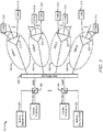
- FIG. 1 is a schematic diagram of an embodiment of a PON sub-network system 100 where embodiments of the present disclosure may operate.
- the PON sub-network system 100 may be an optical access network or part of an optical access network that comprises an OLT 110, a plurality of ONUs 120, and a plurality of ODNs A-D 130.
- the OLT 110 may be coupled to one or more ODNs 130 and each of the ODNs 130 may be coupled to a set of ONUs 120.
- the PON sub-network system 100 may be a communications network that does not comprise any active components to distribute data between the OLT 110 and the ONUs 120.
- the PON sub-network system 100 may use the passive optical components that include, but are not limited to isolators, circulators, filters, and unpowered splitters, in the ODN 130 (e.g. ODN A 130) to transport data between the OLT 110 and the ONUs 120.
- the PON sub-network system 100 may comprise one or more active components, such as optical amplifiers and/or power splitters.
- the PON sub-network system 100 may be implemented as a Next Generation Access (NGA) system, such as an XGPON, which may have a downstream bandwidth of about 10 Gb/s and an upstream bandwidth of at least about 2.5 Gb/s.
- NGA Next Generation Access
- the PON sub-network system 100 may be implemented as an EPON, a 10 Gigabit EPON, an APON, a BPON, a GPON, a WDM PON, a TDM PON, a TWDM PON, and/or combinations thereof.
- the OLT 110 may be any device, such as an OLT line card, that is configured to communicate with the ONUs 120 and external network (not shown). Specifically, the OLT 110 may act as an intermediary between the external network (e.g. a service provider network) and the ONUs 120. For instance, the OLT 110 may forward data received from the external network to the ONUs 120 and forward data received from the ONUs 120 onto the external network.
- the specific configuration of the OLT 110 may vary depending on the type of PON sub-network system 100, in an embodiment, the OLT 110 may comprise a transmitter and a receiver.
- the OLT 110 may comprise a converter that converts the network protocol into the PON protocol.
- the OLT 110 converter may also convert the PON protocol into the network protocol.
- the OLT 110 may be located at a central location, such as a central office, but may be located at other locations as well.
- the ODNs A-D 130 may be a data distribution system, which may comprise optical fiber cables, couplers, splitters, distributors, and/or other network devices.
- the optical fiber cables, couplers, splitters, distributors, and/or other equipment may be passive optical components.
- the optical fiber cables, couplers, splitters, distributors, and/or other network devices may be components that do not require any power to distribute data signals between the OLT 110 and the ONUs 120.
- ODNs A-D 130 may comprise one or a plurality of active components, such as optical amplifiers.
- the ODNs A-D 130 may extend from the OLT 110 to the ONUs 120 in a branching configuration as shown in FIG. 1 , but may be alternatively configured in any other point to multi-point configuration.
- ODNs A-D 130 may also be referenced as an optical access network and may be used interchangeably throughout this disclosure.
- the ONUs 120 may be any devices that are configured to communicate with the OLT 110 and a customer or user (not shown). Specifically, the ONUs 120 may act as an intermediary between the OLT 110 and the customer. For instance, the ONUs 120 may forward data received from the OLT 110 to the customer and forward data received from the customer onto the OLT 110.
- the ONUs 120 may comprise a tunable optical transmitter configured to send optical signals to the OLT 110 and a tunable optical receiver configured to select one of the downstream wavelength within an ODN 130 and receive optical signals in one downstream channel from the OLT 110.
- the transmitters for the ONUs 120 may comprise tunable lasers configured to tune to different wavelengths (e.g. ⁇ 1 - ⁇ 8 ). Additionally, the ONUs 120 may comprise a converter that converts the optical signal into electrical signals for the customer, such as signals in the Ethernet or asynchronous transfer mode (ATM) protocol, and a second transmitter and/or receiver that may send and/or receive the electrical signals to/from a customer device. In some embodiments, ONUs 120 and optical network terminals (ONTs) are similar, and thus the terms are used interchangeably throughout the disclosure. The ONUs 120 may be typically located at one or more distributed locations, such as the customer premises, but may also be located at other locations as well.
- ATM asynchronous transfer mode
- ONTs optical network terminals
- the PON sub-network system 100 may be arranged such that one or more ODNs 130 are coupled to the OLT 110.
- the OLT 110 may be coupled to a plurality of ODNs 130, where each of the ODNs 130 is coupled to a set of ONUs 120.
- a first set of ONUs 120 may be coupled to ODN A 130;
- a second set of ONUs 120 may be coupled to ODN B 130;
- a third set of ONUs 120 may be coupled to ODN C 130;
- a fourth set of ONUs 120 may be coupled to ODN D 130.
- Each ODN 130 (e.g. ODN A 130) may comprise a splitter (e.g.
- the OLT 110 may be configured such that OLT resources (e.g. tunable transmitters) may be dynamically allocated to reach any of the ODNs A-D 130. Allocating OLT resources amongst the ODNs A-D 130 within the PON sub-network system 100 will be discussed in more detail in below.
- OLT resources e.g. tunable transmitters
- upstream refers to the direction that the optical signals travel from an ONU 120 to an OLT 110.
- downstream refers to the direction that the optical signals travel from an OLT 110 to an ONU 120.
- channel and “wavelength band” may be used interchangeably throughout this disclosure and may refer to a wavelength or range of wavelengths used to encode, transmit, and/or receive data.
- a downstream channel and/or wavelength band may have a wavelength value of about 1596 nanometers (nm) with a tolerance of plus or minus 0.1 nm for a certain downstream channel.
- an upstream channel and/or wavelength band may have wavelength value of about 1524 nanometers (nm) with a tolerance of plus or minus 0.2nm to 0.3nm for a certain upstream channel.
- nm nanometers
- tunable transmitter may be interpreted throughout this disclosure to be a tunable laser without a modulator or a tunable laser with a modulator.
- FIG. 2 is a schematic diagram of an embodiment of a network element 200 within a PON sub-network.
- the network element 200 may be an OLT 110, as described in FIG. 1 , or a port within an OLT 110.
- the network element 200 may be suitable for implementing one or more embodiments of systems, methods, and schemes disclosed herein, such as method 1500.
- the network element 200 may be configured to transmit and/or receive optical signals that include, but are not limited to TWDM based transmissions over an optical fiber.
- the network element 200 may be implemented in a single node or the functionality of network element 200 may be implemented in a plurality of nodes.
- the term network element encompasses a broad range of devices of which network element 200 is merely an example.
- Network element 200 is included for purposes of clarity of discussion, but is in no way meant to limit the application of the present disclosure to a particular network element embodiment or class of network element embodiments. At least some of the features/methods described in the disclosure may be implemented in a network apparatus or component such as a network element 200. For instance, the features/methods in the disclosure may be implemented using hardware, firmware, and/or software installed to run on hardware.
- the network element 200 may comprise transceivers (Tx/Rx) 210, which may be transmitters, receivers, or combinations thereof.
- Tx/Rx 210 may be coupled to a plurality of PON ports 220 (e.g. downstream interfaces) for transmitting and/or receiving frames from ONUs within an optical access networks and a Tx/Rx 210 coupled to a plurality of external network ports 250 (e.g. upstream interfaces) for transmitting and/or receiving frames from nodes with an external network, such as a metro network or a service provider core network.
- a processor 230 may be coupled to the Tx/Rxs 210 to process the frames and/or determine which nodes to send frames to.
- the processor 230 may comprise one or more multi-core processors and/or memory devices 232, which may function as data stores, buffers, etc.
- Processor 230 may be implemented as a general processor or may be part of one or more application specific integrated circuits (ASICs), field programmable gate array (FPGA), and/or digital signal processors (DSPs).
- ASICs application specific integrated circuits
- FPGA field programmable gate array
- DSPs digital signal processors
- Processor 230 may comprise a reconfiguration module 234, which may implement the methods discussed herein, such as scheduling transmission of optical signals over one or more ODNs.
- the reconfiguration module 234 may determine the current traffic load for each of the ODNs and dynamically allocate a transmitter within a transmitter array to transmit the corresponding optical signal. In other words, the reconfiguration module 234 may select any of the transmitters and instruct the transmitter to be tuned to a specified wavelength in order to transmit optical signals over any one of the ODNs within a PON sub-network.
- the reconfiguration module 234 may be implemented within the network element 200 when the network element 200 is an OLT. In another alternative embodiment, the reconfiguration module 234 may be implemented on a separate network element 200 external to an OLT.
- the PON ports 220 and/or external network ports 250 may comprise electrical and/or optical transmitting and/or receiving components.
- a design that is still subject to frequent change may be preferred to be implemented in software, because re-spinning a hardware implementation is more expensive than re-spinning a software design.
- a design that is stable that will be produced in large volume may be preferred to be implemented in hardware, for example in an ASIC, because for large production runs the hardware implementation may be less expensive than the software implementation.
- a design may be developed and tested in a software form and later transformed, by well-known design rules, to an equivalent hardware implementation in an application specific integrated circuit that hardwires the instructions of the software. In the same manner as a machine controlled by a new ASIC is a particular machine or apparatus, likewise a computer that has been programmed and/or loaded with executable instructions may be viewed as a particular machine or apparatus.
- any processing of the present disclosure may be implemented by causing a processor (e.g., a general purpose central processing unit (CPU) inside a computer system) in a computer system (e.g., an OLT or an ONU) to execute a computer program.
- a computer program product can be provided to a computer or a mobile device using any type of non-transitory computer readable media.
- the computer program product may be stored in a non-transitory computer readable medium in the computer or the network device.
- Non-transitory computer readable media include any type of tangible storage media. Examples of non-transitory computer readable media include magnetic storage media (such as floppy disks, magnetic tapes, hard disk drives, etc.), optical magnetic storage media (e.g.
- the computer program product may also be provided to a computer or a network device using any type of transitory computer readable media. Examples of transitory computer readable media include electric signals, optical signals, and electromagnetic waves. Transitory computer readable media can provide the program to a computer via a wired communication line (e.g. electric wires, and optical fibers) or a wireless communication line.
- a wired communication line e.g. electric wires, and optical fibers
- FIG. 3 is a schematic diagram of an embodiment of a reconfigurable PON architecture for a PON sub-network 300.
- the PON sub-network 300 comprises a plurality of tunable transmitter arrays A-D 302, a plurality of multiple channel receivers 304, a 4x4 cyclic AWG wavelength router 308, a plurality of ODNs A-D 310, a plurality of splitters 312, and a plurality of tunable ONUs (T-ONU) 314.
- the tunable transmitter arrays A-D 302 may comprise a plurality of tunable transmitters (not shown in FIG. 3 ).
- the tunable transmitters may be configured to tune to a plurality of wavelengths that may be used to encode and transmit data.
- the transmitter arrays A-D 302 may be located within a single OLT or may be located in different OLTs. In one embodiment, when the data traffic for the PON sub-network 300 is relatively low, some of the OLT resources, such as the tunable transmitter arrays A-D 302 and/or tunable transmitters may be put into sleep mode to conserve power consumption.
- the multiple channel receivers 304 comprises a plurality of channel receivers that are each configured to receive an upstream encoded wavelength (e.g. wavelength ⁇ 1u ).
- the number of channel receivers within the multiple channel receivers 304 is the same as the maximum number of upstream wavelengths transmitted by the T-ONUs 314. For instance, if the tunable transmitters within T-ONUs 314 are configured to encode data using a maximum of eight different upstream wavelengths, then the multiple channel receivers 304 comprise eight different channel receivers.
- the plurality of channel receivers may be used to establish point to point connections for upstream transmission from the T-ONUs 314. Implementing point to point connections may be beneficial in backhaul type networks (e.g. wireless backhaul network) or immersive video tele-presenting applications (e.g. tele-dynamic show).
- the upstream encoded wavelengths received by each multiple channel receiver 304 may correspond to the wavelengths transmitted by the tunable transmitter array 302 for a given wavelength order.
- the multiple channel receiver 304 corresponding to tunable transmitter array A 302 may receive upstream data encoded using wavelengths ⁇ 1u, ⁇ 2u, and ⁇ 3u, which may come from one ODN 310 or multiple ODNs 310.
- the downstream wavelengths and the corresponding upstream wavelengths may not have the same wavelength value.
- downstream wavelength ⁇ 1d may have a wavelength range of 1596 nm to 1605 nm
- the upstream wavelength ⁇ 1u may have a wavelength range of 1524 nm to 1544 nm.
- labeling wavelengths ⁇ 1d, ⁇ 2d, and ⁇ 3d, and ⁇ 1u, ⁇ 2u, and ⁇ 3u represents the order of wavelength values from the shortest wavelength value to the longest wavelength.
- the wavelengths labeled ⁇ 1d and ⁇ 1u have the shortest wavelength in the downstream direction and upstream direction, respectively
- the wavelengths labeled ⁇ 3d and ⁇ 3u have the longest wavelength in the downstream direction and upstream direction, respectively.
- the T-ONU 310 if one downstream wavelength ⁇ 1d is received by one of the T-ONUs 310, the T-ONU 310 that received downstream wavelength ⁇ 1d can emit an upstream wavelength ⁇ 1u to reach the corresponding optical channel that emits downstream wavelength ⁇ 1d or the same port receiver of the 4x4 cyclic AWG wavelength router 308.
- labeling wavelengths such as ⁇ 1d and ⁇ 1u, represent the wavelengths the transceiver at the OLT emits and receives, respectively.
- An optical filter 306 such as a WDM filter, may be positioned in between the AWG wavelength router 308 and the transmitter arrays A-D 302/multiple channel receivers 304.
- the optical filters 306 may provide wavelength sensitive loss, isolation and/or return loss.
- the optical filters 306 may be in-line, wavelength selective, components that allow a specific range of wavelengths to pass through and/or reflect with low attenuation.
- the optical filters 306 may be used to separate out upstream optical signals from downstream optical signals such that upstream optical signals are reflected to the multiple channel receivers 304 and the downstream optical signals are passed through to the 4x4 cyclic AWG wavelength router 308.
- the optical filters 306 may be placed between the 4x4 cyclic AWG wavelength router 308 and the ODN networks 310.
- the optical filters 306 may reside in the OLT or ODNs 310.
- the tunable transmitter arrays A-D 302 and the multiple channel receivers 304 are coupled to 4x4 cyclic AWG wavelength router 308.
- the 4x4 cyclic AWG wavelength router 308 may comprise four input ports and four output ports.
- the 4x4 notation refers the number of input ports (e.g. 4 inputs) and the number of output ports (4 outputs) in a downstream direction.
- the input ports are coupled to the tunable transmitter arrays A-D 302 and each of the output ports are coupled to one of the ODNs A-D 310.
- one of the output ports for the 4x4 cyclic AWG wavelength router 308 is coupled to ODN A 310 and a separate output port is coupled to ODN B 310.
- the 4x4 cyclic AWG wavelength router 308 may be configured to route predefined wavelength bands with certain channel spacing received at an input port to a predetermined output port.
- the 4x4 cyclic AWG wavelength router 308 may be configured with a cyclic nature that output wavelengths in a repeating order (e.g. based on input ports) for each of the output ports.
- the 4x4 cyclic AWG wavelength router 308 may be a hybrid device that comprises a 4x4 AWG wavelength router and a 4x4 power splitter (not shown in FIG. 3 ) that may amplify downstream and upstream light functions.
- FIG. 3 illustrates the use of a 4x4 cyclic AWG wavelength router 308, other optical routing or switch devices, such as a multi-input port and multi-output port, free space, cyclic wavelength router or switching device, may be used route wavelengths received at an input to a designated output in repeating order.
- other optical routing or switch devices such as a multi-input port and multi-output port, free space, cyclic wavelength router or switching device, may be used route wavelengths received at an input to a designated output in repeating order.
- the 4x4 cyclic AWG wavelength router 308 may output the downstream optical signals allocated for the ODNs A-D 310 to reach the T-ONUs 314.
- ODNs A-D 310 and T-ONUs 314 may be substantially similar to ODNs 130 and ONUs 120 as described in FIG. 1 , respectively.
- each of the ODNs A-D 310 may comprise a splitter 312 that receives the downstream optical signal from the 4x4 cyclic AWG wavelength router 308.
- the splitter 312 may be a passive optical device that splits the downstream optical signal to a plurality of split optical signals and sends the split optical signals to different T-ONUs 314.
- Each of the splitters 312 may be configured as a 1:32, 1:64, 1:128, or any other splitter ratio and may split an incoming downstream optical signal based on the different wavelengths used to encode the incoming downstream optical signal.
- T-ONUs 314 may comprise tunable transmitters used to transmit optical signals in the upstream direction.
- the splitters 312 may merge the different upstream wavelengths received from T-ONUs 314 into a single upstream optical fiber and send the merged multi-wavelength upstream optical signal to the 4x4 cyclic AWG wavelength router 308.
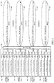
- FIG. 4 is a schematic diagram of an embodiment of a reconfigurable PON sub-network 400 with an eight wavelength tuning range.
- the reconfigurable PON sub-network 400 comprises a plurality of tunable transmitter arrays A-D 402, a 4x4 cyclic AWG wavelength router 308 and a plurality of ODNs A-D 310.
- Each of the tunable transmitter arrays A-D 402 comprises a plurality of tunable transmitters 404.
- each of the tunable transmitters 404 may be configured to tune to eight different wavelength bands.
- the tunable transmitters 404 may be able to encode and transmit data using eight different optical channels.
- the nominal channel space between two wavelength bands e.g.
- the actual channel space may be about 0.6 nm for a tolerance of about 0.1 nm or about 0.4 nm (about 50 GHz) for a tolerance of about 0.2 nm.
- each tunable transmitter arrays A-D 402 the tunable transmitters 404 may be coupled to an optical coupler 406 (e.g. MMI or star coupler).
- the optical coupler 406 combines the optical signals transmitted from each of the tunable transmitters 404 for a given tunable transmitter array 402 (e.g. tunable transmit array A 402) and outputs a combined optical signal that feeds into the 4x4 cyclic AWG wavelength router 308.
- the tunable transmitter arrays A-D 402, tunable transmitters 404, and optical coupler 406 will be discussed in more detail in FIG. 14 .
- FIG. 4 also illustrates the wavelength output arrangement of the 4x4 cyclic AWG wavelength router 308 over the different ODNs A-D 310.
- the 4x4 cyclic AWG wavelength router 308 may be configured with a cyclic nature that repeats orders and may allocate predefined wavelength bands received from the input ports to certain output ports.
- the 4x4 cyclic AWG wavelength router 308 routes wavelength bands ⁇ 1 - ⁇ 8 to different ODNs A-D 310 depending on the input of the 4x4 cyclic AWG wavelength router 308.
- Each of the inputs of the 4x4 cyclic AWG wavelength router 308 are coupled to different tunable transmitter arrays A-D 402. Using FIG.
- the eight different wavelength bands that may be outputted to ODN A 310 are labeled as ⁇ A1 , ⁇ B2 , ⁇ C3 , ⁇ D4 , ⁇ A5 , ⁇ B6 , ⁇ C7 , and ⁇ D8 .
- Label ⁇ A1 indicates that the 4x4 cyclic AWG wavelength router 308 has been configured such that wavelength band ⁇ 1 is emitted from tunable transmitter array A 402; label ⁇ B2 indicates that the wavelength band ⁇ 2 is emitted from tunable transmitter array B 402; label ⁇ C3 indicates that the wavelength band ⁇ 3 is emitted from tunable transmitter array C 402; and label ⁇ D4 indicates that the wavelength band ⁇ 4 is emitted from tunable transmitter array D 402.
- the label ⁇ A5 indicates that the 4x4 cyclic AWG wavelength router 308 has been configured to return to the input associated with tunable transmitter array A 402 to emit wavelength band ⁇ 5 for ODN A 310.
- the 4x4 cyclic AWG wavelength router 308 repeats the same order for ⁇ 2 , ⁇ 3 , and ⁇ 4 .
- labels ⁇ B6 , ⁇ C7 , and ⁇ D8 correspond to the 4x4 cyclic AWG wavelength router 308 routing inputs that correspond to the tunable transmitter array B 402, tunable transmitter array C 402, and tunable transmitter array D 402 to emit wavelength bands ⁇ 6 , ⁇ 7 , and ⁇ 8 , respectively. Similar label notation is used for the wavelength bands ⁇ 1 - ⁇ 8 that 4x4 cyclic AWG wavelength router 308 outputs to the other ODNs B-D 310.
- Each of the tunable transmitters 404 within each of the tunable transmitter arrays A-D 402 may access any of the ODNs A-D 310 by tuning the tunable transmitters 404 to encode data at a certain wavelength band. For example, for a tunable transmitter 404 within tunable transmitter array A 402 (e.g. top most tunable transmitter 404) to access ODN A 310, the tunable transmitter 404 may be tuned to wavelength bands ⁇ 1 or ⁇ 5 .
- the tunable transmitter 404 may be tuned to wavelength bands ⁇ 2 or ⁇ 6 ; to access ODN C 310, the tunable transmitter 404 may be tuned to wavelength bands ⁇ 3 or ⁇ 7 ; and to access ODN D 310, the tunable transmitter 404 may be tuned to wavelength bands ⁇ 4 or ⁇ 8 .
- Other tunable transmitters 404 within other tunable transmitter arrays B-D 402 may be tuned to other wavelength bands in order to access the same ODNs A-D 310 as shown in FIG. 4 .
- Persons of ordinary skill in the art are aware that other combination of wavelength sequences may be output to the ODNs A-D 310 and that the disclosure is not limited to only the specific applications in the FIG. 4 other figures (e.g. FIGS. 5-13 ).
- the use and discussion in FIG. 4 and other figures (e.g. FIGS. 5-13 ) are only an example to facilitate ease of description and explanation.
- the OLT may dynamically increase or decrease the data rate capacity (e.g. bandwidth) for each of the ODNs A-D 310 by adjusting the number of wavelengths allocated to encode and transmit data for each of the ODNs A-D 310.
- the OLT may initially allocate transmission of four downstream wavelengths on each ODNs A-D 310 simultaneously using the 16 different tunable transmitters.
- the OLT may dynamically adjust the number of downstream wavelengths assigned to each ODNs A-D 310 by re-tuning one or more of the tunable laser transmitters 404 in one or more tunable transmitter arrays A-D 402.
- the OLT may dynamically allocate wavelengths for the tunable transmitter arrays A-D 402 to transmit within one ODN.
- FIG. 5 is a schematic diagram of another embodiment of a reconfigurable PON sub-network 500 with an eight wavelength tuning range.
- FIG. 5 illustrates an example case of allocating OLT resource for downstream transmission of wavelengths over different ODNs A-D 310 using 16 different tunable transmitters 404.
- each of the tunable transmitter arrays A-D 402 comprise four different tunable transmitters.
- the four tunable transmitters 404 within tunable transmitter array A 402 may be tuned to wavelength bands ⁇ 1 , ⁇ 5 , ⁇ 2 , and ⁇ 4 ; the four tunable transmitters 404 within tunable transmitter array B 402 may be tuned to wavelength bands ⁇ 1 , ⁇ 2 , ⁇ 6 , and ⁇ 4 ; the four tunable transmitters 404 within tunable transmitter array C 402 may be tuned to wavelength bands ⁇ 1 , ⁇ 2 , ⁇ 3 , and ⁇ 7 ; and the four tunable transmitters 404 within tunable transmitter array D 402 may be tuned to wavelength bands ⁇ 8 , ⁇ 2 , ⁇ 3 , and ⁇ 4 .
- the 16 different tunable transmitters 404 encode data using the wavelength bands to access different ODNs A-D 310.
- two tunable transmitters 404 within each of the tunable transmitter arrays A-D 402 are used to transmit wavelengths labeled ⁇ A1 , ⁇ B2 , ⁇ C3 , ⁇ D4 , ⁇ A5 , ⁇ B6 , ⁇ C7 , and ⁇ k D8 for ODN A 310.
- two tunable transmitters 404 within tunable transmitter array A 402 emit the wavelengths labeled ⁇ A1 and ⁇ A5 ;
- two tunable transmitters 404 within tunable transmitter array B 402 emit the wavelengths labeled ⁇ B2 and ⁇ B6 ;
- two tunable transmitters 404 within tunable transmitter array C 402 emit the wavelengths labeled ⁇ C3 and ⁇ C7 ;
- two tunable transmitters 404 within tunable transmitter array D 402 emit the wavelengths labeled ⁇ D4 and ⁇ D8 .
- a tunable transmitter 404 within tunable transmitter array A 402 emits the wavelength labeled ⁇ A2 ; for ODN C 310, a tunable transmitter 404 within tunable transmitter array B 402, tunable transmitter array C 402, and tunable transmitter array D 402 emit the wavelengths labeled ⁇ B4 , ⁇ C1 , and ⁇ D2 , respectively; and for ODN D 310, a tunable transmitter 404 within tunable transmitter array A 402, tunable transmitter array B 402, tunable transmitter array C 402, and tunable transmitter array D 402 emit the wavelengths labeled ⁇ A4 , ⁇ B1 , ⁇ C2 , and ⁇ D3 , respectively.
- each of the wavelength bands (e.g. ⁇ A1 ) represents about a 10 Gb/s optical channel
- the transmission of wavelength bands ⁇ A1 , ⁇ B2 , ⁇ C3 , ⁇ D4 , ⁇ A5 , ⁇ B6 , ⁇ C7 , and ⁇ D8 over ODN A 310 may represent a data rate of about 80 Gb/s allocated to ODN A 310.
- ODN B 310, ODN C 310, and ODN D 310 may be allocated with a data rate of 10 Gb/s, 30 Gb/s, and 40 Gb/s, respectively.
- the number of wavelength bands allocated for each of the ODNs A-D 310 may be dependent on traffic load and other network conditions for the ODNs A-D 310.
- the OLT that houses tunable transmitter arrays A-D 402 may determine that ODN A 310 may be associated with a large enterprise network that may require a substantial amount of OLT resources during a certain time period (e.g. during a work day), and ODN B 310 may be associated with residential networks that may require relatively less OLT resources during the same time period.
- the OLT may allocate more OLT resources (e.g. tunable transmitters 404) to the large enterprise network by tuning eight of the 16 tunable transmitters 404 to wavelength bands allocated for ODN A 310 for the certain time period.
- the OLT resources may subsequently be reconfigured or reallocated to dynamically provide a more efficient, scalable, flexible, and reconfigurable PON network. For instance, after the certain time period expires (e.g. during a weekend), the OLT resources may be reconfigured such that relatively less OLT resources are allocated to ODN A 310 and relatively more OLT resources are allocated to ODN B 310.
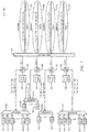
- FIG. 6 is a schematic diagram of an embodiment of a reconfigurable PON sub-network 600 with an eight wavelength tuning range and comprises a plurality of multiple channel receivers to receive upstream wavelengths from a plurality of ONUs.
- the reconfigurable PON sub-network 600 is substantially similar to the reconfigurable PON sub-network 400 in FIG. 4 except that the reconfigurable PON sub-network 600 further comprises a plurality of multiple channel receivers and a plurality of optical filters 306 that route upstream optical signals to the multiple channel receivers prior to reaching the 4x4 cyclic AWG wavelength router 308.
- Each of the multiple channel receivers comprises a 1x8 demultiplexer 602 and a plurality of channel receivers Rx1-Rx8 604.
- Each of the 1x8 demultiplexers 602 may be an active or a passive demultiplexer that receives an upstream optical signal within one of the ODNs A-D 310 and separates out the different wavelength bands within the optical signal and sends the wavelength bands to the corresponding channel receivers 604.
- Each of the upstream wavelength bands received at the 1x8 demultiplexers 602 may be from tunable ONU transmitters associated with each of the ODNs A-D 310.
- the number of output channels in the upstream direction for the 1x8 demultiplexers 602 may be the same as the number of maximum upstream wavelengths tunable by the ONUs.
- the multiple channel receiver that is coupled to ODN A 310 may receive an upstream optical signal that comprises wavelength bands ⁇ AU1 , ⁇ AU2 , ⁇ AU3 , ⁇ AU4 , ⁇ AU5 , ⁇ AU 6, ⁇ AU7 , and ⁇ AU8 that are transmitted from ONUs coupled to ODN A 310;
- the multiple channel receiver that is coupled to ODN B 310 may receive an upstream optical signal that comprises wavelength bands ⁇ BU1 , ⁇ BU2 , ⁇ BU3 , ⁇ BU4 , ⁇ BU5 , ⁇ BU6 , ⁇ BU7 , and ⁇ BU8 that are transmitted from ONUs coupled to ODN B 310;
- the multiple channel receiver that is coupled to ODN C 310 may receive an upstream optical signal that comprises wavelength bands ⁇ CU1 , ⁇ CU2 , ⁇ CU3 , ⁇ CU4 , ⁇ CU5 , ⁇ CU6
- the labels ⁇ AU1 - ⁇ AU8 , ⁇ BU1 - ⁇ BU8 , ⁇ CU1 - ⁇ CU8 , and ⁇ DU1 - ⁇ DU8 represent the different upstream wavelength bands ⁇ 1 - ⁇ 8 received from the different ODNs A-D 310.
- the different upstream wavelength bands for each ODN A-D 310 in FIG. 6 represents that any ONU or user may tune its upstream tunable transmitter to any one of the upstream wavelengths bands ⁇ 1 - ⁇ 8 .
- the number of channel receivers 604 for each ODN A-D 310 may correspond to the maximum number of wavelengths bands the ONUs are able to tune to. In FIG.
- each of the channel receivers Rx1, Rx2, Rx3, Rx4, Rx5, Rx6, Rx7, Rx8 604 may be designated to receive the data encoded in one of the upstream wavelength bands ⁇ 1 , ⁇ 2 , ⁇ 3 , ⁇ 4 , ⁇ 5 , ⁇ 6 , ⁇ 7 , and ⁇ 8 , respectively.
- the ONUs may be able to implement point to multi-point connections and point to point connections simultaneously, which may be beneficial in backhaul type networks (e.g. wireless backhaul) or immersive video tele-presenting applications (e.g. tele-dynamic show).
- backhaul type networks e.g. wireless backhaul
- immersive video tele-presenting applications e.g. tele-dynamic show
- FIG. 6 uses case example, there are 16 tunable transmitters and 32 channel receivers at OLT side, where 16 of the 32 channel receivers may be used for point to point connections.
- FIG. 6 illustrates that each of the ODNs A-D 310 are able to transport eight upstream wavelengths to the OLT, the actual number of upstream wavelength transmitted for each of the ODNs A-D 310 may have a range of about four for symmetrical downstream and upstream TWDM-PON architecture.
- FIG. 7 is a schematic diagram of another embodiment of a reconfigurable PON sub-network 700 with an eight wavelength tuning range and comprises a plurality of multiple channel receivers to receive upstream wavelengths from a plurality of ONUs.
- the reconfigurable PON sub-network 700 is substantially similar to the reconfigurable PON sub-network 600 in FIG. 6 except that the optical filters 306 are positioned between the tunable transmitter array 402 and the 4x4 cyclic AWG wavelength router 308. Each optical filter 306 routes the upstream wavelength bands to the 1x8 demultiplexer 602 after the upstream wavelengths pass through the 4x4 cyclic AWG wavelength router 308.
- the 4x4 cyclic AWG wavelength router 308 may be configured such that upstream wavelengths ⁇ 1 - ⁇ 8 received by the ODNs A-D 310 in the upstream direction is output to different 4x4 cyclic AWG wavelength router 308 ports 1-4 based on a repeating and predetermined order. As shown in FIG. 7 , the upstream optical signal received from port 1 of the 4x4 cyclic AWG wavelength router 308 may comprise upstream wavelengths ⁇ A1 , ⁇ B2 , ⁇ C3 , ⁇ D4 , ⁇ A5 , ⁇ B6 , ⁇ C7 , and ⁇ D8 .
- Labels ⁇ A1 and ⁇ A5 may represent that wavelengths ⁇ 1 and ⁇ 5 are from ODN A 310; labels ⁇ B2 and ⁇ B6 may represent that wavelengths ⁇ 2 and ⁇ 6 are from ODN B 310; labels ⁇ C3 and ⁇ C7 may represent that wavelengths ⁇ 3 and ⁇ 7 are from ODN C 310; and labels ⁇ D4 and ⁇ D8 may represent that wavelengths ⁇ 4 and ⁇ 8 are from ODN D 310.
- Wavelengths received at ports 2-4 of the 4x4 cyclic AWG wavelength router 308 may be labeled in a similar notation as described for port 1.
- the upstream wavelengths received at ports 1-4 of the 4x4 cyclic AWG wavelength router 308 may then be inputted into the optical filters 306.
- the optical filters 306 may send the upstream wavelengths to the 1x8 demultiplexer 602 which separates out and sends the corresponding wavelengths to the channel receivers Rx1-Rx8 604.
- FIG. 1x8 demultiplexer 602 which separates out and sends the corresponding wavelengths to the channel receivers Rx1-Rx8 604.
- channel receivers Rx1, Rx2, Rx3, Rx4, Rx5, Rx6, Rx7, and Rx8 604 that are coupled to port 1 of the 4x4 cyclic AWG wavelength router 308 may receive ⁇ A1 , ⁇ B2 , ⁇ C3 , ⁇ D4 , ⁇ A5 , ⁇ B6 , ⁇ C7 , and ⁇ D8 , respectively, after passing through the 1x8 demultiplexer 602.
- the other channel receivers Rx1-Rx8 604 that are coupled to ports 2-4 of the 4x4 cyclic AWG wavelength router 308 may be designated to receive certain wavelengths from different ODNs A-D 310 similar to channel receivers Rx1-Rx8 604 that are coupled to port 1 of the 4x4 cyclic AWG wavelength router 308. Similar to FIG. 6 , the number of channel receivers in each multiple channel receiver and the number of outputs channels for the 1x8 demultiplexer 602 may be the same number as the maximum number upstream wavelengths transmitted by the ONUs.
- FIG. 8 is a schematic diagram of another embodiment of a reconfigurable PON sub-network 800 with an eight wavelength tuning range and comprises a plurality of multiple channel receivers to receive upstream wavelengths from a plurality of ONUs.
- FIG. 8 illustrates an example case of receiving upstream transmission from the different ODNs A-D 310.
- the allocation of OLT resources e.g. tunable transmitter arrays 402 and tunable transmitters 404 for downstream transmission may be substantially similar to FIG. 5 .
- the OLT has allocated eight downstream wavelengths to ODN A 310, one downstream wavelength to ODN B 310, three downstream wavelengths to ODN C 310, and four downstream wavelengths to ODN D 310.
- the number of upstream wavelength allocated to each ODN A-D 310 may be adjusted (e.g. increased or decreased) to match the number of downstream wavelengths allocated for downstream transmission.
- the downstream and upstream wavelengths may correspond to each other such that that both the downstream and upstream wavelengths traverse through the same ports of 4x4 cyclic AWG wavelength router 308.
- the ONUs transmit upstream wavelengths ⁇ A1u , ⁇ B2u , ⁇ C3u , ⁇ D4u , ⁇ A5u , ⁇ B6u , ⁇ C7u , and ⁇ D8u , which correspond with the downstream wavelengths ⁇ A1d , ⁇ B2d , ⁇ C3d , ⁇ D4d , ⁇ A5d , ⁇ B6d , ⁇ C7d , and ⁇ D8d .
- the channel receivers 604 receive upstream wavelengths that correspond to the wavelengths that the tunable transmitter arrays A-D 402 provided in the downstream direction.
- the 1x8 demultiplexer 602 that is coupled to the tunable transmitter array A 402 may receive wavelengths labeled ⁇ A1u , ⁇ A5u , ⁇ A2u , and ⁇ A4u , which correspond with ⁇ A1d , ⁇ A5d , ⁇ A2d , and ⁇ A4d , respectively;
- the 1x8 demultiplexer 602 that is coupled to the tunable transmitter array B 402 may receive wavelengths labeled ⁇ B1u , ⁇ B2u , ⁇ B6u , and ⁇ B4u , which correspond with ⁇ B1d , ⁇ B2d , ⁇ B6d , and ⁇ B4d , respectively;
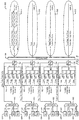
- FIG. 9 is a schematic diagram of an embodiment of a reconfigurable PON sub-network 900 with a 16 wavelength tuning range.
- the reconfigurable PON sub-network 900 comprises a plurality of tunable transmitter arrays A-D 902, a 4x4 cyclic AWG wavelength router 308 and a plurality of ODNs A-D 310.
- Each of the tunable transmitter arrays A-D 902 comprises a plurality of tunable transmitters 904 that are configured to tune to 16 different wavelength bands, which are denoted as ⁇ 1 - ⁇ 16 .
- the tunable transmitters 904 may be coupled to an optical coupler 906 (e.g. MMI or star coupler).
- an optical coupler 906 e.g. MMI or star coupler
- the optical coupler 906 combines the optical signals transmitted from each of the tunable transmitters 904 for a given tunable transmitter array 902 (e.g. tunable transmit array A 902) and outputs a combined optical signal that feeds into the 4x4 cyclic AWG wavelength router 308.
- the tunable transmitter arrays A-D 902, tunable transmitters 904, and optical coupler 906 will be discussed in more detail in FIG. 14 .
- FIG. 9 illustrates four tunable transmitters 904 within each tunable transmitter array 902, in other embodiments, the number of tunable transmitters 904 may range from more than 4 to 8 tunable transmitters 904.
- FIG. 9 illustrates the wavelength output arrangement of the 4x4 cyclic AWG wavelength router 308 over the different ODNs A-D 310.
- the 4x4 cyclic AWG wavelength router 308 assigns different tunable transmitter arrays A-D 902 to output the different wavelength bands ⁇ 1 - ⁇ 16 over different ODNs A-D 310.
- FIG. 9 illustrates the wavelength output arrangement of the 4x4 cyclic AWG wavelength router 308 over the different ODNs A-D 310.
- the 16 different wavelength bands that may be output to ODN A 310 are labeled as ⁇ A1 , ⁇ B2 , ⁇ C3 , ⁇ D4 , ⁇ A5 , ⁇ B6 , ⁇ C7 , ⁇ D8 , ⁇ A9 , ⁇ B10 , ⁇ C11 , ⁇ D12 , ⁇ A13 , ⁇ B14 , ⁇ C15 , and ⁇ D16 .
- Label ⁇ A1 indicates that the 4x4 cyclic AWG wavelength router 308 has been configured such that wavelength band ⁇ 1 is emitted from tunable transmitter array A 902; label ⁇ B2 indicates that the wavelength band ⁇ 2 is emitted from tunable transmitter array B 902; label ⁇ C3 indicates that the wavelength band ⁇ 3 is emitted from tunable transmitter array C 902; and label ⁇ D4 indicates that the wavelength band ⁇ 4 is emitted from tunable transmitter array D 902.
- the labels ⁇ A5, ⁇ A9, and ⁇ A13 indicate that the 4x4 cyclic AWG wavelength router 308 has been setup to repeat the tunable transmitter array 902 input order and assigns tunable transmitter array A 902 to emit wavelength bands ⁇ 5, ⁇ 9 , and ⁇ 13 , respectively.
- the remaining wavelength bands ⁇ 86, ⁇ B10 , and ⁇ B14 , ⁇ C7 ⁇ C11 , and ⁇ C14 , and ⁇ D8 , ⁇ D12 , and ⁇ D16 may correspond to tunable transmitter array B 902, tunable transmitter array C 902, and tunable transmitter array D 902, respectively. Similar notation is used for the wavelength bands ⁇ 1 - ⁇ 16 emitted on the other ODNs B-D 310.
- FIG. 10 is a schematic diagram of another embodiment of a reconfigurable PON sub-network 1000 with a 16 wavelength tuning range. Similar to FIG. 5 , FIG. 10 illustrates a use case example of transmitting wavelengths over different ODNs A-D 310 using a total of 16 different tunable transmitters 904 that are configured to tune to 16 different wavelength bands ⁇ 1 - ⁇ 16 . In FIG. 10 , each of the tunable transmitter arrays A-D 902 comprise four different tunable transmitters.
- the four tunable transmitters 904 within tunable transmitter array A 902 may be tuned to wavelength bands ⁇ 1 , ⁇ 5 , ⁇ 9 , and ⁇ 13 ; the four tunable transmitters 904 within tunable transmitter array B 902 may be tuned to wavelength bands ⁇ 7 , ⁇ 11 , ⁇ 3 , and ⁇ 5 ; the four tunable transmitters 904 within tunable transmitter array C 902 may be tuned to wavelength bands ⁇ 4 , ⁇ 8 , ⁇ 12 , and ⁇ 16 ; and the four tunable transmitters 904 within tunable transmitter array D 902 may be tuned to wavelength bands ⁇ 1 , ⁇ 5 , ⁇ 9 , and ⁇ 13 .
- the 16 different tunable transmitters 904 may access different ODNs A-D 310 by encoding data using different wavelength bands.
- no wavelengths are transmitted downstream over ODNs C and D 310 because the ONUs for the ODNs C and D 310 do not have any data request. Instead, wavelength resources have been moved to ODN A and B 310.
- all four of the tunable transmitters 904 within the tunable transmitter array A 902 are used to transmit wavelengths ⁇ A1 , ⁇ A5 , ⁇ A9 , and ⁇ A13 for ODN A 310.
- the 12 remaining tunable transmitters 904 in tunable transmitter arrays B-D 902 are tuned to wavelength bands that are allocated to ODN B 310. As shown in FIG.
- wavelengths ⁇ B3 , ⁇ C4 , ⁇ D1 , ⁇ B7 , ⁇ C8 , ⁇ D5 , ⁇ B11 , ⁇ C12 , ⁇ D9 , ⁇ B15 , ⁇ C16 , and ⁇ D13 are transmitted over ODN B 310.
- the OLT may dynamically allocate OLT resources depending on the network conditions and traffic loads over the ODNs A-D 310.
- FIG. 11 is a schematic diagram of an embodiment of a reconfigurable PON sub-network 1100 with a 16 wavelength tuning range and comprises a plurality of multiple channel receivers to receive upstream wavelengths from a plurality of ONUs.
- the reconfigurable PON sub-network 1100 is substantially similar to the reconfigurable PON sub-network 600 in FIG. 6 except that each of the multiple channel receivers comprises sixteen channel receivers Rx1-Rx16 1104 and a 1x16 demultiplexer 1102.
- FIG. 11 illustrates that the reconfigurable PON sub-network 1100 may comprise a total of 64 channel receivers 1104 and four 1x16 demultiplexers.
- Each of the 1x16 demultiplexers 1102 may be an active or a passive demultiplexer that receives an upstream optical signal within one of the ODNs A-D 310 and separates out the different wavelength bands within the optical signal and sends the wavelength bands to the corresponding channel receivers 604.
- Each of the upstream wavelength bands received at the 1x16 demultiplexers 602 may be from tunable ONU transmitters associated with each of the ODNs A-D 310.
- the multiple channel receiver that is coupled to ODN A 310 may receive an upstream optical signal that comprises wavelength bands ⁇ Au1 , ⁇ Au2 , ⁇ Au3 , ⁇ Au4 ... ⁇ Au13 , ⁇ Au14 , ⁇ Au15 , and ⁇ Au16 transmitted from ONUs coupled to ODN A 310;
- the multiple channel receiver that is coupled to ODN B 310 may receive an upstream optical signal that comprises wavelength bands ⁇ Bu1 , ⁇ Bu2 , ⁇ Bu3 , ⁇ Bu4 ... ⁇ Bu13 , ⁇ Bu14 , ⁇ Bu15 , and ⁇ Bu16 transmitted from ONUs coupled to ODN B 310;
- the multiple channel receiver that is coupled to ODN C 310 may receive an upstream optical signal that comprises wavelength bands ⁇ Cu1 , ⁇ Cu2 , ⁇ Cu3 , ⁇ Cu4 ... ⁇ Cu13 , ⁇ Cu14 , ⁇ Cu15 , and ⁇ Cu16 transmitted from ONUs coupled to ODN C 310;
- the different upstream wavelength bands for each ODN A-D 310 in FIG. 11 represents that any ONU or user may tune its upstream tunable transmitter to any one of the upstream wavelengths bands ⁇ 1 , ⁇ 2 , ⁇ 3 , ⁇ 4 ... ⁇ 13 , ⁇ 14 , ⁇ 15 , and ⁇ 16 .
- Similar embodiments of the reconfigurable PON sub-networks 700 and 800 may also be applied to receiving 16 different upstream wavelength bands.
- the optical filters 306 may be moved such that the optical filters 306 are positioned between the tunable transmitter array 902 and the 4x4 cyclic AWG wavelength router 308. Similar to FIG. 7 , in this instance, the upstream optical signal received by the 1x16 demultiplexer that corresponds to the tunable transmitter array A 902 may comprise upstream wavelengths ⁇ Au1 , ⁇ Bu2 , ⁇ Cu3 , ⁇ Du4 ... ⁇ Au13 , ⁇ Bu14 , ⁇ Cu15 , and ⁇ Du16 ; the upstream optical signal received by the 1x16 demultiplexer that corresponds to the tunable transmitter array B 902 may comprise upstream wavelengths ⁇ Au2 , ⁇ Bu3 , ⁇ Cu4 , ⁇ Du1 ... ⁇ Au14 , ⁇ Bu15 , ⁇ Cu16 , and ⁇ Du13 ; the upstream optical signal received by the 1x16 demultiplexer that corresponds to the tunable transmitter array C 902 may comprise upstream wavelengths
- the reconfigurable PON sub-network 1100 may comprise a total of 32 tunable transmitters and 64 channel receivers 1004, which may make the PON sub-network 1100 more flexible for ever-growth application.
- FIG. 12 is a schematic diagram of an embodiment of a generalized reconfigurable PON sub-network 1200 with a wavelength tuning range of NxN wavelengths in the downstream direction.
- the reconfigurable PON sub-network 1200 may comprise N tunable transmitter arrays 1202.
- Each of the transmitter arrays A-N 1202 comprises K different tunable transmitters 1204 (e.g. 8 tunable transmitters 1204).
- the K different tunable transmitters 1204 may be coupled to an optical coupler 1206 that combines the different wavelengths from the tunable transmitters 1204 to output a single optical signal that is fed into an NxN cyclic AWG wavelength router 1208.
- Each of the tunable transmitters 1204 may be configured with a tuning range that is equal to or less than NxN.
- the NxN cyclic AWG wavelength router 1208 may have N downstream inputs from the tunable transmitter arrays 1202 and N output s for the N different ODNs 310. Similar to FIG. 6 and 9 , each of the tunable transmitters 1204 may access any of the ODNs A-N 310.
- the generalized reconfigurable PON sub-network 1200 may allocate the tunable transmitters 1204 to other ODNs 310.
- the OLT may dynamically increase or decrease one or more of the ODNs' 310 data rate.
- FIG. 13 is a schematic diagram of another embodiment of a generalized reconfigurable PON sub-network 1300 with a wavelength tuning range of NxN wavelengths in the downstream direction and upstream direction.
- PON sub-network 1300 may be substantially similar to PON sub-network 1200 except that the PON sub-network 1300 may further comprise a plurality of multiple channel receivers.
- Each of the multiple channel receivers may comprise a 1xM demultiplexer 1302 and M number of channel receivers 1304 and receive the upstream optical signals from the optical filters 306.
- Each of the 1xM demultiplexers 1302 may be an active or a passive demultiplexer that receives an upstream optical signal within one of the ODNs A-N 310 and separates out the different wavelength bands within the optical signal and sends the wavelength bands to the corresponding channel receivers 1304.
- Each of the upstream wavelength bands received at the 1xM demultiplexers 1302 may be from tunable ONU transmitters associated with each of the ODNs A-N 310.
- M represents the number of upstream wavelengths that the ONU transmitters are able to tune.
- the multiple channel receiver that is coupled to ODN A 310 may receive an upstream optical signal that comprises wavelength bands ⁇ AU1 , ⁇ AU2 , ⁇ AU3 , ⁇ AU4 ... ⁇ AU(M-3) , ⁇ AU(M-2) , ⁇ AU(M-1) , and ⁇ AUM transmitted from ONUs coupled to ODN A 310;
- the multiple channel receiver that is coupled to ODN B 310 may receive an upstream optical signal that comprises wavelength bands ⁇ Bu1 , ⁇ BU2 , ⁇ BU3 , ⁇ BU4 ... ⁇ BU(M-3) , ⁇ BU(M-2) , ⁇ BU(M-1) , and ⁇ BUM transmitted from ONUs coupled to ODN B 310;
- the multiple channel receiver that is coupled to ODN N 310 may receive an upstream optical signal that comprises wavelength bands ⁇ NU1 , ⁇ NU2 , ⁇ NU3 , ⁇ NU4 ... ⁇ NU(
- ODN A 310 may transport wavelengths ⁇ AD1 , ⁇ AD2 , ⁇ AD3 , ⁇ AD4 ... ⁇ AD(NxN-3) , ⁇ AD(NxN-2) , ⁇ AD(NxN-1) , and ⁇ ADNxN ;
- ODN B 310 may transport wavelengths ⁇ BD1 , ⁇ BD2 , ⁇ BD3 , ⁇ BD4 ... ⁇ BD(NxN-3) , ⁇ BD(NxN-2) , M BD(NxN-1) , and ⁇ BDNxN ;
- ODN N 310 may transport wavelengths ⁇ ND1 , ⁇ ND2 , ⁇ ND3 , ⁇ ND4 ... ⁇ ND(NxN-3) , ⁇ ND(NxN-2) , ⁇ ND(NxN-1) , and ⁇ NDNxN .
- FIG. 14 is a schematic diagram of an embodiment of a tunable transmitter array 1400.
- the tunable transmitter array 1400 that comprises a plurality of tunable laser with modulators A-M 1402, an optical coupler 1404.
- the tunable laser with modulator A-M 1402 may be configured to perform external modulation.
- the tunable transmitter array 1400 may comprise tunable lasers without a modulator that is configured to perform direct modulation.
- the type of modulation implemented may depend on the downstream data rate. For example, if the data rate for a wavelength band is about 2.5 Gb/s, the tunable transmitter may be a laser without a modulator that performs direct modulation.
- the tunable laser with modulator 1402 may be configured to perform external modulation. If the tunable laser with modulator 1402 is configured to perform external modulation, then the external modulator may be monolithically integrated with the tunable laser, such as electroabsorption modulator or Mach-Zehnder modulator. In another embodiment, the external modulator may not be integrated and located on a separate device.
- the optical coupler 1404 may be integrated or external to the tunable lasers with modulators 1402.
- the optical coupler 1404 may receive M different inputs from M different tunable lasers with modulators 1402 and output a combined optical signal based on the M different inputs into one fiber or waveguide.
- the combined optical signal may then sent to the one of the input ports of a cyclic AWG wavelength router.
- M may be represented as an integer and may represent the number of tunable transmitters within a tunable transmitter array 1400. As shown in FIGS. 4 , 5 , 9 , and 10 , M may have a value of about four. In other embodiments, the M value may be more than four (e.g. eight).
- the optical coupler 1404 may be an optical device, such as an MMI or star coupler that are not wavelength sensitive.
- the optic coupler 1404 may not be configured as a wavelength transmission selection device and may combine all input wavelength light into the optical coupler's 1404 output port.
- the optical coupler 1404 may not filter any of the wavelengths or otherwise limit the wavelengths that pass through to the output port.
- FIG. 15 is a flowchart of an embodiment of a method 1500 that dynamically allocates OLT resources over a plurality of ODNs.
- Method 1500 may be implemented within an OLT or some other similar device within a PON network.
- Method 1500 may start at step 1502 and determine the traffic load for each of the ODNs within a sub-network. After determining the traffic load, method 1500 may move to step 1504 and allocate OLT resources dynamically depending on the traffic load for each of the ODNs. Recall that the OLT may tune the tunable transmitters within a tunable transmitter array to different wavelengths when allocating the OLT resources to the ODNs. Afterwards, method 1500 may move to step 1506 and transmit downstream optical signals over the ODNs using the allocated OLT resources.
- Method 1500 may proceed to step 1508 to receive upstream optical signals for every ODN.
- Method 1500 may implement step 1508 before, in parallel, and/or after steps 1502, 1504, and 1506.
- Method 1500 may implement step 1508 using point to point connections between channel receivers in the OLT and the ONUs. The point to point connections may be implemented simultaneously with point to multi-point connections.
- R R l + k * (R u - R l ), wherein k is a variable ranging from 1 percent to 100 percent with a 1 percent increment, i.e., k is 1 percent, 2 percent, 3 percent, 4 percent, 5 percent, ..., 50 percent, 51 percent, 52 percent, ..., 95 percent, 96 percent, 97 percent, 98 percent, 99 percent, or 100 percent.
- any numerical range defined by two R numbers as defined in the above is also specifically disclosed.
Landscapes
- Engineering & Computer Science (AREA)
- Computer Networks & Wireless Communication (AREA)
- Signal Processing (AREA)
- Optical Communication System (AREA)
Description
- A passive optical network (PON) is a system for providing network access over "the last mile." In a downstream direction, the PON may be a point-to-multi-point (P2MP) network comprising an optical line terminal (OLT) at a central office (CO), a plurality of optical network units (ONUs) at one or more customer premises, and an optical distribution network (ODN) connecting the OLT and the ONUs. PONs may also comprise remote nodes (RNs) located between the OLTs and the ONUs, for example, at the end of a road where multiple users reside. In recent years, time division multiplexing (TDM) PONs and wavelength division multiplexing (WDM) PONs have been deployed in order to increase bandwidth. In TDM PONs, each ONU may send and receive data across every available wavelength, but only at dedicated time intervals. In WDM PONs, each ONU may send and receive data in a continuous manner, but at dedicated wavelengths. A hybrid PON combining TDM with WDM can support higher capacity so that an increased number of users can be served by a single OLT with sufficient bandwidth per user.
- The rapid growth of internet traffic continues to push broadband optical access networks to support higher data rates and better quality of services. For instance, the capacities of optical channels in some optical networks, such as PONs, are approaching about 40 gigabits per second (Gb/s). Although the demand to increase bandwidth and throughput continue to grow, designs for improving optical networks are often constrained by cost, power, and size requirements. Moreover, today's PONs may not be efficiently utilizing network resources. For example, in a PON, OLT resources allocated for one ODN may not be shared with an ONU allocated for a different ODN. C. BOCK ET AL: "Hybrid WDM/TDM PON using the AWG FSR and featuring centralized light generation and dynamic bandwidth allocation", JOURNAL OF LIGHTWAVE TECHNOLOGY, vol. 23, no. 12, 1 December 2005 (2005-12-01), pages 3981-3988, ISSN: 0733-8724, DOI: 10.1109/JLT.2005.853138 discloses the functionality of this AWG is to route optical signals generated by the OLT laser stack to each of the network branches to which the OLT will serve and the authors here make use of the free spectral range (FSR) periodical routing property of AWGs to route more than one wavelength to each output port...The use of the FSR for routing purposes requires that both central and remote AWGs be designed to match the bandpass wavelengths" (See page 3981, right column, last paragraph-3983, left column, second paragraph). NAKAMURA HIROTAKA ET AL: "40Gbit/s-class-[lambda]-tunable WDM/ TDM-PON using tunable B-Tx and cyclic AWG router for flexible photonic aggregation networks", 2012 38TH EUROPEAN CONFERENCE AND EXHIBITION ON OPTICAL COMMUNICATIONS, OSA, 16 September 2012 (2012-09-16), pages 1-3 discloses: "
Fig. 1 shows the configuration of the proposed system. The OLT consists of LCs that output downstream signals and receive upstream signals, a DWBA controller, and a photonic aggregator using an 4 x 4 cyclic AWG that connects 4-LCs to 4-PON branches (4-PBs). Each LC has a tunable Tx (4λ) and a burst-mode receiver (B-Rx). The optical network unit (ONU) has a tunable B-Tx and a burst-mode receiver. Tunable Txs in the LC and the ONU output the downstream and upstream signals while switching its output wavelength according to instructions from the DWBA controller. The four wavelengths for the upstream are 1271, 1291, 1311, and 1331 nm (20-nm spacing), in which optical devices in 40 GbE market can be utilized. The wavelengths for the downstream signals are 1575.4, 1577.0, 1578.7, and 1580.4 nm (200-GHz spacing). This wavelength allocation is suitable for the smooth migration from 10G-EPON and XG-PON" (seeFIG. 1 , p. 2, 1). SHACHAF Y ET AL: "A Full-duplex Access Network based on CWDM-routed PONs", OPTICAL FIBER COMMUNICATION/NATIONAL FIBER OPTIC ENGINEERS CONFERENCE, 2008. OFC/NFOEC 2008. CONFERENCE ON, IEEE, PISCATAWAY, NJ, USA, 24 February 2008 (2008-02-24), pages 1-3, ISBN: 978-1-55752-856-8 discloses the application of polarization-division-multiplexing in presented, demonstrating full-duplex transmission in an access network architecture employing RSOA-based ONUs (See Abstract). MAURICE GAGNAIRE ET AL: "A new control plane for next-generation WDM-PON access systems", ACCESS NETWORKS&WORKSHOPS, 2007. ACCESSNETS '07. SECOND INTER NATIONAL CONFERENCE ON, IEEE, PI, 1 August 2007 (2007-08-01), pages 1-8, ISBN: 978-1-4244-1149-8 discloses the first objective is to assign connections to upstream optical channels in order to optimize network utilization and the latter enables to reallocate dynamically the number of optical channels to the various PONs of the system (see Abstract). Obviously, the document is also related to upstream optical channels and the number of channels which to adapted to the various PONs (See Abstract). -
US 7 245 829 B1 (SINDILE PIA [CA]) 17 July 2007 (2007-07-17) discloses a network arrangement for aggregation of tunable sources in a photonic network with tunable transmitters, a plurality of receivers in customer groups and using cyclic AWG for wavelength multiplexing and demultiplexing. -
WO 2011/053200 A1 (ERICSSON TELEFON AB L M [SE]; CHEN JIAJIA [SE]; WOSINSKA LENA [SE]) 5 May 2011 (2011-05-05) discloses a WDM PON network using NxN AWG for multiplexing and demultiplexing in remote nodes. - The present invention is defined by the appended claims. All embodiments that do not fall within the scope of the claims have to be understood as examples useful for understanding the invention.
- For a more complete understanding of this disclosure, reference is now made to the following brief description, taken in connection with the accompanying drawings and detailed description, wherein like reference numerals represent like parts.
-
FIG. 1 is a schematic diagram of an embodiment of a PON sub-network system where embodiments of the present disclosure may operate. -
FIG. 2 is a schematic diagram of an embodiment of a network element within a PON sub-network. -
FIG. 3 is a schematic diagram of an embodiment of a reconfigurable PON architecture for a PON sub-network. -
FIG. 4 is a schematic diagram of an embodiment of a reconfigurable PON sub-network with an eight wavelength tuning range. -
FIG. 5 is a schematic diagram of another embodiment of a reconfigurable PON sub-network with an eight wavelength tuning range. -
FIG. 6 is a schematic diagram of an embodiment of a reconfigurable PON sub-network with an eight wavelength tuning range and comprises a plurality of multiple channel receivers to receive upstream wavelengths from a plurality of ONUs. -
FIG. 7 is a schematic diagram of another embodiment of a reconfigurable PON sub-network with an eight wavelength tuning range and comprises a plurality of multiple channel receivers to receive upstream wavelengths from a plurality of ONUs. -
FIG. 8 is a schematic diagram of another embodiment of a reconfigurable PON sub-network with an eight wavelength tuning range and comprises a plurality of multiple channel receivers to receive upstream wavelengths from a plurality of ONUs. -
FIG. 9 is a schematic diagram of an embodiment of a reconfigurable PON sub-network with a 16 wavelength tuning range. -
FIG. 10 is a schematic diagram of another embodiment of a reconfigurable PON sub-network with a 16 wavelength tuning range. -
FIG. 11 is a schematic diagram of an embodiment of a reconfigurable PON sub-network with a 16 wavelength tuning range and comprises a plurality of multiple channel receivers to receive upstream wavelengths from a plurality of ONUs. -
FIG. 12 is a schematic diagram of an embodiment of a generalized reconfigurable PON sub-network with a wavelength tuning range of NxN wavelengths in the downstream direction. -
FIG. 13 is a schematic diagram of another embodiment of a generalized reconfigurable PON sub-network with a wavelength tuning range of NxN wavelengths in the downstream direction and upstream direction. -
FIG. 14 is a schematic diagram of an embodiment of a tunable transmitter array. -
FIG. 15 is a flowchart of an embodiment of a method that dynamically allocates OLT resources over a plurality of ODNs. - It should be understood at the outset that, although an illustrative implementation of one or more embodiments are provided below, the disclosed systems and/or methods may be implemented using any number of techniques, whether currently known or in existence. The disclosure should in no way be limited to the illustrative implementations, drawings, and techniques illustrated below, including the exemplary designs and implementations illustrated and described herein, but may be modified within the scope of the appended claims.
- There exist various PON protocols or standards, for example, asynchronous transfer mode PON (APON) and the broadband PON (BPON) defined by the International Telecommunication Union (ITU) Telecommunication Standardization Sector (ITU-T) G.983 standard, Gigabit PON (GPON) defined by the ITU-T G.984 standard, and Ethernet PON (EPON) defined by the Institute of Electrical and Electronics Engineers (IEEE) 802.3ah standard. Currently, GPON and EPON have been deployed worldwide for broadband services, providing aggregated bandwidth up to 2.5 Gb/s. To satisfy ever-increasing bandwidth demands from end users, next generation 10 Gigabits (10G) PON, sometimes known as XG-PON or 10G EPON, with aggregated bandwidth of 10 Gb/s have been standardized and are ready for large scale deployment. Beyond 10G PONs, future generations of optical access technologies, such as WDM PON, TWDM PON, Orthogonal Frequency Division Multiplexed (OFDM) PON and Optical Code Division Multiplexed (OCDM) PON, has been proposed and demonstrated with aggregated bandwidth of 40 Gb/s or higher.
- Among these technologies, TWDM PON has been selected by the Full Service Access Network (FSAN) community as a primary broadband solution for future access networks. Such TWDM PON systems can provide 40 Gb/s aggregated capacity with 1:64 splitting ratio and 40 kilometers (km) reach, meeting operators' requirements for future broadband services. A new set of standards on TWDM PON may pave the way for future large scale deployment. With multiple wavelengths and wavelength tunability, TWDM PON allows enhanced network functionalities unavailable in previous generations of pure TDM PONs. Incremental bandwidth upgrade and load balancing may be achieved in TWDM PON systems using tunable transmitters on an OLT line card. Energy efficient solutions may be implemented for TWDM PONs using dynamic wavelength routing.
- Disclosed herein are at least one method, apparatus, and/or system for implementing one or more reconfigurable optical access network architectures that allocate OLT resources dynamically within a PON (e.g. TWDM PON). The reconfigurable optical access network architecture may arrange one or more ODNs in a PON to form a sub-network. Rather than having OLT resources confined to communicating over a single ODN, the OLT resources may be shared amongst the ODNs within a sub-network. In particular, each tunable transmitter in a tunable transmitter array may be able to access each of the ODNs located within the sub-network. In one embodiment, the tunable transmitter may dynamically access each of the ODNs using a cyclic arrayed waveguide grating (AWG) wavelength router and an optical coupler, such as a multi-mode interference coupler (MMI). One or more tunable transmitters within a tunable transmitter array may provide wavelengths for one or more ODNs. Additionally, the ODNs in a sub-network may be able to simultaneously implement a point to point and a point to multi-point connection with the OLT in the sub-network (e.g. a point to point and a point to multi-point connection can coexist in the sub-network). Specifically, the OLT may be configured to allocate a multiple channel receiver array that comprises a plurality of channel receivers. The number of channel receivers within the multiple channel receiver array is equal to the maximum number of upstream wavelengths transmitted by the ONUs.
-
FIG. 1 is a schematic diagram of an embodiment of aPON sub-network system 100 where embodiments of the present disclosure may operate. ThePON sub-network system 100 may be an optical access network or part of an optical access network that comprises anOLT 110, a plurality ofONUs 120, and a plurality ofODNs A-D 130. TheOLT 110 may be coupled to one or more ODNs 130 and each of theODNs 130 may be coupled to a set ofONUs 120. In one embodiment, thePON sub-network system 100 may be a communications network that does not comprise any active components to distribute data between theOLT 110 and theONUs 120. Instead, thePON sub-network system 100 may use the passive optical components that include, but are not limited to isolators, circulators, filters, and unpowered splitters, in the ODN 130 (e.g. ODN A 130) to transport data between theOLT 110 and theONUs 120. In another embodiment, thePON sub-network system 100 may comprise one or more active components, such as optical amplifiers and/or power splitters. ThePON sub-network system 100 may be implemented as a Next Generation Access (NGA) system, such as an XGPON, which may have a downstream bandwidth of about 10 Gb/s and an upstream bandwidth of at least about 2.5 Gb/s. Alternatively, thePON sub-network system 100 may be implemented as an EPON, a 10 Gigabit EPON, an APON, a BPON, a GPON, a WDM PON, a TDM PON, a TWDM PON, and/or combinations thereof. - In an embodiment, the
OLT 110 may be any device, such as an OLT line card, that is configured to communicate with theONUs 120 and external network (not shown). Specifically, theOLT 110 may act as an intermediary between the external network (e.g. a service provider network) and theONUs 120. For instance, theOLT 110 may forward data received from the external network to theONUs 120 and forward data received from theONUs 120 onto the external network. Although the specific configuration of theOLT 110 may vary depending on the type ofPON sub-network system 100, in an embodiment, theOLT 110 may comprise a transmitter and a receiver. When the external network is using a network protocol, such as Ethernet or Synchronous Optical Networking/Synchronous Digital Hierarchy (SONET/SDH), that is different from the PON protocol used in thePON sub-network system 100, theOLT 110 may comprise a converter that converts the network protocol into the PON protocol. TheOLT 110 converter may also convert the PON protocol into the network protocol. TheOLT 110 may be located at a central location, such as a central office, but may be located at other locations as well. - In an embodiment, the
ODNs A-D 130 may be a data distribution system, which may comprise optical fiber cables, couplers, splitters, distributors, and/or other network devices. In an embodiment, the optical fiber cables, couplers, splitters, distributors, and/or other equipment may be passive optical components. Specifically, the optical fiber cables, couplers, splitters, distributors, and/or other network devices may be components that do not require any power to distribute data signals between theOLT 110 and theONUs 120. Alternatively,ODNs A-D 130 may comprise one or a plurality of active components, such as optical amplifiers. TheODNs A-D 130 may extend from theOLT 110 to theONUs 120 in a branching configuration as shown inFIG. 1 , but may be alternatively configured in any other point to multi-point configuration.ODNs A-D 130 may also be referenced as an optical access network and may be used interchangeably throughout this disclosure. - In an embodiment, the
ONUs 120 may be any devices that are configured to communicate with theOLT 110 and a customer or user (not shown). Specifically, theONUs 120 may act as an intermediary between theOLT 110 and the customer. For instance, theONUs 120 may forward data received from theOLT 110 to the customer and forward data received from the customer onto theOLT 110. Although the specific configuration of theONUs 120 may vary depending on the type ofPON sub-network system 100, in an embodiment, theONUs 120 may comprise a tunable optical transmitter configured to send optical signals to theOLT 110 and a tunable optical receiver configured to select one of the downstream wavelength within anODN 130 and receive optical signals in one downstream channel from theOLT 110. The transmitters for theONUs 120 may comprise tunable lasers configured to tune to different wavelengths (e.g. λ1-λ8). Additionally, theONUs 120 may comprise a converter that converts the optical signal into electrical signals for the customer, such as signals in the Ethernet or asynchronous transfer mode (ATM) protocol, and a second transmitter and/or receiver that may send and/or receive the electrical signals to/from a customer device. In some embodiments,ONUs 120 and optical network terminals (ONTs) are similar, and thus the terms are used interchangeably throughout the disclosure. TheONUs 120 may be typically located at one or more distributed locations, such as the customer premises, but may also be located at other locations as well. - The
PON sub-network system 100 may be arranged such that one or more ODNs 130 are coupled to theOLT 110. As shown inFIG. 1 , theOLT 110 may be coupled to a plurality ofODNs 130, where each of theODNs 130 is coupled to a set ofONUs 120. UsingFIG. 1 as an example, a first set ofONUs 120 may be coupled toODN A 130; a second set ofONUs 120 may be coupled toODN B 130; a third set ofONUs 120 may be coupled toODN C 130; and a fourth set ofONUs 120 may be coupled toODN D 130. Each ODN 130 (e.g. ODN A 130) may comprise a splitter (e.g. a 1:64 splitter) and other suitable components (e.g. fiber) to transport the optical signal from the OLT to each of theONUs 120. Additionally, theOLT 110 may be configured such that OLT resources (e.g. tunable transmitters) may be dynamically allocated to reach any of theODNs A-D 130. Allocating OLT resources amongst theODNs A-D 130 within thePON sub-network system 100 will be discussed in more detail in below. - Throughout this disclosure the term "upstream" refers to the direction that the optical signals travel from an
ONU 120 to anOLT 110. The term "downstream" refers to the direction that the optical signals travel from anOLT 110 to anONU 120. Additionally, the term "channel" and "wavelength band" may be used interchangeably throughout this disclosure and may refer to a wavelength or range of wavelengths used to encode, transmit, and/or receive data. For example, a downstream channel and/or wavelength band may have a wavelength value of about 1596 nanometers (nm) with a tolerance of plus or minus 0.1 nm for a certain downstream channel. In another example, an upstream channel and/or wavelength band may have wavelength value of about 1524 nanometers (nm) with a tolerance of plus or minus 0.2nm to 0.3nm for a certain upstream channel. Persons of ordinary skill in the art are aware that other tolerance ranges (e.g. ±0.2 nm) and other wavelength values may exist for a downstream channel, an upstream channel, and/or wavelength band. The term "tunable transmitter" may be interpreted throughout this disclosure to be a tunable laser without a modulator or a tunable laser with a modulator. -
FIG. 2 is a schematic diagram of an embodiment of anetwork element 200 within a PON sub-network. For example, thenetwork element 200 may be anOLT 110, as described inFIG. 1 , or a port within anOLT 110. Thenetwork element 200 may be suitable for implementing one or more embodiments of systems, methods, and schemes disclosed herein, such asmethod 1500. Thenetwork element 200 may be configured to transmit and/or receive optical signals that include, but are not limited to TWDM based transmissions over an optical fiber. Thenetwork element 200 may be implemented in a single node or the functionality ofnetwork element 200 may be implemented in a plurality of nodes. One skilled in the art will recognize that the term network element encompasses a broad range of devices of whichnetwork element 200 is merely an example.Network element 200 is included for purposes of clarity of discussion, but is in no way meant to limit the application of the present disclosure to a particular network element embodiment or class of network element embodiments. At least some of the features/methods described in the disclosure may be implemented in a network apparatus or component such as anetwork element 200. For instance, the features/methods in the disclosure may be implemented using hardware, firmware, and/or software installed to run on hardware. - As shown in
FIG. 2 , thenetwork element 200 may comprise transceivers (Tx/Rx) 210, which may be transmitters, receivers, or combinations thereof. A Tx/Rx 210 may be coupled to a plurality of PON ports 220 (e.g. downstream interfaces) for transmitting and/or receiving frames from ONUs within an optical access networks and a Tx/Rx 210 coupled to a plurality of external network ports 250 (e.g. upstream interfaces) for transmitting and/or receiving frames from nodes with an external network, such as a metro network or a service provider core network. Aprocessor 230 may be coupled to the Tx/Rxs 210 to process the frames and/or determine which nodes to send frames to. Theprocessor 230 may comprise one or more multi-core processors and/ormemory devices 232, which may function as data stores, buffers, etc.Processor 230 may be implemented as a general processor or may be part of one or more application specific integrated circuits (ASICs), field programmable gate array (FPGA), and/or digital signal processors (DSPs). -
Processor 230 may comprise areconfiguration module 234, which may implement the methods discussed herein, such as scheduling transmission of optical signals over one or more ODNs. Thereconfiguration module 234 may determine the current traffic load for each of the ODNs and dynamically allocate a transmitter within a transmitter array to transmit the corresponding optical signal. In other words, thereconfiguration module 234 may select any of the transmitters and instruct the transmitter to be tuned to a specified wavelength in order to transmit optical signals over any one of the ODNs within a PON sub-network. In one embodiment, thereconfiguration module 234 may be implemented within thenetwork element 200 when thenetwork element 200 is an OLT. In another alternative embodiment, thereconfiguration module 234 may be implemented on aseparate network element 200 external to an OLT. ThePON ports 220 and/orexternal network ports 250 may comprise electrical and/or optical transmitting and/or receiving components. - It is understood that by programming and/or loading executable instructions onto the
network element 200, at least one of theprocessor 230,reconfiguration module 234, Tx/Rxs 210,memory 232,PON ports 220, and/orexternal network ports 250 are changed, transforming thenetwork element 200 in part into a particular machine or apparatus, e.g., a multi-core forwarding architecture, having the novel functionality taught by the present disclosure. It is fundamental to the electrical engineering and software engineering arts that functionality that can be implemented by loading executable software into a computer can be converted to a hardware implementation by well-known design rules. Decisions between implementing a concept in software versus hardware typically hinge on considerations of stability of the design and numbers of units to be produced rather than any issues involved in translating from the software domain to the hardware domain. Generally, a design that is still subject to frequent change may be preferred to be implemented in software, because re-spinning a hardware implementation is more expensive than re-spinning a software design. Generally, a design that is stable that will be produced in large volume may be preferred to be implemented in hardware, for example in an ASIC, because for large production runs the hardware implementation may be less expensive than the software implementation. Often a design may be developed and tested in a software form and later transformed, by well-known design rules, to an equivalent hardware implementation in an application specific integrated circuit that hardwires the instructions of the software. In the same manner as a machine controlled by a new ASIC is a particular machine or apparatus, likewise a computer that has been programmed and/or loaded with executable instructions may be viewed as a particular machine or apparatus. - It should be understood that any processing of the present disclosure may be implemented by causing a processor (e.g., a general purpose central processing unit (CPU) inside a computer system) in a computer system (e.g., an OLT or an ONU) to execute a computer program. In this case, a computer program product can be provided to a computer or a mobile device using any type of non-transitory computer readable media. The computer program product may be stored in a non-transitory computer readable medium in the computer or the network device. Non-transitory computer readable media include any type of tangible storage media. Examples of non-transitory computer readable media include magnetic storage media (such as floppy disks, magnetic tapes, hard disk drives, etc.), optical magnetic storage media (e.g. magneto-optical disks), compact disc read-only memory (ROM) (CD-ROM), compact disc recordable (CD-R), compact disc rewritable (CD-R/W), digital video disc (DVD), Blu-ray (registered trademark) disc (BD), and semiconductor memories (such as mask ROM, programmable ROM (PROM), erasable PROM), flash ROM, and random access memory (RAM)). The computer program product may also be provided to a computer or a network device using any type of transitory computer readable media. Examples of transitory computer readable media include electric signals, optical signals, and electromagnetic waves. Transitory computer readable media can provide the program to a computer via a wired communication line (e.g. electric wires, and optical fibers) or a wireless communication line.
-
FIG. 3 is a schematic diagram of an embodiment of a reconfigurable PON architecture for aPON sub-network 300. ThePON sub-network 300 comprises a plurality of tunable transmitter arrays A-D 302, a plurality ofmultiple channel receivers 304, a 4x4 cyclicAWG wavelength router 308, a plurality ofODNs A-D 310, a plurality ofsplitters 312, and a plurality of tunable ONUs (T-ONU) 314. The tunable transmitter arrays A-D 302 may comprise a plurality of tunable transmitters (not shown inFIG. 3 ). The tunable transmitters may be configured to tune to a plurality of wavelengths that may be used to encode and transmit data. The transmitter arrays A-D 302 may be located within a single OLT or may be located in different OLTs. In one embodiment, when the data traffic for thePON sub-network 300 is relatively low, some of the OLT resources, such as the tunable transmitter arrays A-D 302 and/or tunable transmitters may be put into sleep mode to conserve power consumption. - The
multiple channel receivers 304 comprises a plurality of channel receivers that are each configured to receive an upstream encoded wavelength (e.g. wavelength λ1u). The number of channel receivers within themultiple channel receivers 304 is the same as the maximum number of upstream wavelengths transmitted by the T-ONUs 314. For instance, if the tunable transmitters within T-ONUs 314 are configured to encode data using a maximum of eight different upstream wavelengths, then themultiple channel receivers 304 comprise eight different channel receivers. The plurality of channel receivers may be used to establish point to point connections for upstream transmission from the T-ONUs 314. Implementing point to point connections may be beneficial in backhaul type networks (e.g. wireless backhaul network) or immersive video tele-presenting applications (e.g. tele-dynamic show). - The upstream encoded wavelengths received by each
multiple channel receiver 304 may correspond to the wavelengths transmitted by thetunable transmitter array 302 for a given wavelength order. UsingFIG. 3 as an example, if tunabletransmitter array A 302 encodes downstream data using wavelengths λ1d, λ2d, and λ3d, then themultiple channel receiver 304 corresponding to tunabletransmitter array A 302 may receive upstream data encoded using wavelengths λ1u, λ2u, and λ3u, which may come from oneODN 310 ormultiple ODNs 310. The downstream wavelengths and the corresponding upstream wavelengths may not have the same wavelength value. For example, downstream wavelength λ1d may have a wavelength range of 1596 nm to 1605 nm, and the upstream wavelength λ1u may have a wavelength range of 1524 nm to 1544 nm. Instead, labeling wavelengths λ1d, λ2d, and λ3d, and λ1u, λ2u, and λ3u represents the order of wavelength values from the shortest wavelength value to the longest wavelength. For the above downstream and upstream wavelength sequences, the wavelengths labeled λ1d and λ1u have the shortest wavelength in the downstream direction and upstream direction, respectively, and the wavelengths labeled λ3d and λ3u have the longest wavelength in the downstream direction and upstream direction, respectively. In one embodiment, if one downstream wavelength λ1d is received by one of the T-ONUs 310, the T-ONU 310 that received downstream wavelength λ1d can emit an upstream wavelength λ1u to reach the corresponding optical channel that emits downstream wavelength λ1d or the same port receiver of the 4x4 cyclicAWG wavelength router 308. Throughout the disclosure, labeling wavelengths, such as λ1d and λ1u, represent the wavelengths the transceiver at the OLT emits and receives, respectively. - An
optical filter 306, such as a WDM filter, may be positioned in between theAWG wavelength router 308 and the transmitter arrays A-D 302/multiple channel receivers 304. Theoptical filters 306 may provide wavelength sensitive loss, isolation and/or return loss. Theoptical filters 306 may be in-line, wavelength selective, components that allow a specific range of wavelengths to pass through and/or reflect with low attenuation. InFIG. 3 , theoptical filters 306 may be used to separate out upstream optical signals from downstream optical signals such that upstream optical signals are reflected to themultiple channel receivers 304 and the downstream optical signals are passed through to the 4x4 cyclicAWG wavelength router 308. In another embodiment, theoptical filters 306 may be placed between the 4x4 cyclicAWG wavelength router 308 and the ODN networks 310. Theoptical filters 306 may reside in the OLT orODNs 310. - In
FIG. 3 , the tunable transmitter arrays A-D 302 and themultiple channel receivers 304 are coupled to 4x4 cyclicAWG wavelength router 308. The 4x4 cyclicAWG wavelength router 308 may comprise four input ports and four output ports. The 4x4 notation refers the number of input ports (e.g. 4 inputs) and the number of output ports (4 outputs) in a downstream direction. The input ports are coupled to the tunable transmitter arrays A-D 302 and each of the output ports are coupled to one of theODNs A-D 310. For example, one of the output ports for the 4x4 cyclicAWG wavelength router 308 is coupled toODN A 310 and a separate output port is coupled toODN B 310. The 4x4 cyclicAWG wavelength router 308 may be configured to route predefined wavelength bands with certain channel spacing received at an input port to a predetermined output port. The 4x4 cyclicAWG wavelength router 308 may be configured with a cyclic nature that output wavelengths in a repeating order (e.g. based on input ports) for each of the output ports. In one embodiment, the 4x4 cyclicAWG wavelength router 308 may be a hybrid device that comprises a 4x4 AWG wavelength router and a 4x4 power splitter (not shown inFIG. 3 ) that may amplify downstream and upstream light functions. AlthoughFIG. 3 illustrates the use of a 4x4 cyclicAWG wavelength router 308, other optical routing or switch devices, such as a multi-input port and multi-output port, free space, cyclic wavelength router or switching device, may be used route wavelengths received at an input to a designated output in repeating order. - The 4x4 cyclic
AWG wavelength router 308 may output the downstream optical signals allocated for theODNs A-D 310 to reach the T-ONUs 314.ODNs A-D 310 and T-ONUs 314 may be substantially similar toODNs 130 andONUs 120 as described inFIG. 1 , respectively. Additionally, each of theODNs A-D 310 may comprise asplitter 312 that receives the downstream optical signal from the 4x4 cyclicAWG wavelength router 308. Thesplitter 312 may be a passive optical device that splits the downstream optical signal to a plurality of split optical signals and sends the split optical signals to different T-ONUs 314. Each of thesplitters 312 may be configured as a 1:32, 1:64, 1:128, or any other splitter ratio and may split an incoming downstream optical signal based on the different wavelengths used to encode the incoming downstream optical signal. In the upstream direction, T-ONUs 314 may comprise tunable transmitters used to transmit optical signals in the upstream direction. Thesplitters 312 may merge the different upstream wavelengths received from T-ONUs 314 into a single upstream optical fiber and send the merged multi-wavelength upstream optical signal to the 4x4 cyclicAWG wavelength router 308. -
FIG. 4 is a schematic diagram of an embodiment of areconfigurable PON sub-network 400 with an eight wavelength tuning range. Thereconfigurable PON sub-network 400 comprises a plurality of tunable transmitter arrays A-D 402, a 4x4 cyclicAWG wavelength router 308 and a plurality ofODNs A-D 310. Each of the tunable transmitter arrays A-D 402 comprises a plurality oftunable transmitters 404. As shown inFIG. 4 , each of thetunable transmitters 404 may be configured to tune to eight different wavelength bands. In other words, thetunable transmitters 404 may be able to encode and transmit data using eight different optical channels. In one embodiment, the nominal channel space between two wavelength bands (e.g. between λ1 and λ2) may be about 100 gigahertz (GHz) or about 0.8 nm. When factoring the tolerance for each of the optical channel wavelength positions the actual channel space may be about 0.6 nm for a tolerance of about 0.1 nm or about 0.4 nm (about 50 GHz) for a tolerance of about 0.2 nm. - In
FIG. 4 , the eight different wavelength bands that each oftunable transmitters 404 may use to encode optical signals are denoted as λ1-λ8. Within each tunable transmitter arrays A-D 402, thetunable transmitters 404 may be coupled to an optical coupler 406 (e.g. MMI or star coupler). Theoptical coupler 406 combines the optical signals transmitted from each of thetunable transmitters 404 for a given tunable transmitter array 402 (e.g. tunable transmit array A 402) and outputs a combined optical signal that feeds into the 4x4 cyclicAWG wavelength router 308. The tunable transmitter arrays A-D 402,tunable transmitters 404, andoptical coupler 406 will be discussed in more detail inFIG. 14 . -
FIG. 4 also illustrates the wavelength output arrangement of the 4x4 cyclicAWG wavelength router 308 over thedifferent ODNs A-D 310. Recall that the 4x4 cyclicAWG wavelength router 308 may be configured with a cyclic nature that repeats orders and may allocate predefined wavelength bands received from the input ports to certain output ports. For each output port, the 4x4 cyclicAWG wavelength router 308 routes wavelength bands λ1-λ8 todifferent ODNs A-D 310 depending on the input of the 4x4 cyclicAWG wavelength router 308. Each of the inputs of the 4x4 cyclicAWG wavelength router 308 are coupled to different tunable transmitter arrays A-D 402. UsingFIG. 4 as an example, the eight different wavelength bands that may be outputted to ODN A 310 are labeled as λA1, λB2, λC3, λD4, λA5, λB6, λC7, and λD8. Label λA1 indicates that the 4x4 cyclicAWG wavelength router 308 has been configured such that wavelength band λ1 is emitted from tunabletransmitter array A 402; label λB2 indicates that the wavelength band λ2 is emitted from tunabletransmitter array B 402; label λC3 indicates that the wavelength band λ3 is emitted from tunabletransmitter array C 402; and label λD4 indicates that the wavelength band λ4 is emitted from tunabletransmitter array D 402. - The label λA5 indicates that the 4x4 cyclic
AWG wavelength router 308 has been configured to return to the input associated with tunabletransmitter array A 402 to emit wavelength band λ5 forODN A 310. To output wavelength bands λ6, λ7, and λ8 toODN A 310, the 4x4 cyclicAWG wavelength router 308 repeats the same order for λ2, λ3, and λ4. Specifically, labels λB6, λC7, and λD8 correspond to the 4x4 cyclicAWG wavelength router 308 routing inputs that correspond to the tunabletransmitter array B 402, tunabletransmitter array C 402, and tunabletransmitter array D 402 to emit wavelength bands λ6, λ7, and λ8, respectively. Similar label notation is used for the wavelength bands λ1-λ8 that 4x4 cyclicAWG wavelength router 308 outputs to theother ODNs B-D 310. - Each of the
tunable transmitters 404 within each of the tunable transmitter arrays A-D 402 may access any of theODNs A-D 310 by tuning thetunable transmitters 404 to encode data at a certain wavelength band. For example, for atunable transmitter 404 within tunable transmitter array A 402 (e.g. top most tunable transmitter 404) to accessODN A 310, thetunable transmitter 404 may be tuned to wavelength bands λ1 or λ5. To accessODN B 310, thetunable transmitter 404 may be tuned to wavelength bands λ2 or λ6; to accessODN C 310, thetunable transmitter 404 may be tuned to wavelength bands λ3 or λ7; and to accessODN D 310, thetunable transmitter 404 may be tuned to wavelength bands λ4 or λ8. Othertunable transmitters 404 within other tunable transmitter arrays B-D 402 may be tuned to other wavelength bands in order to access thesame ODNs A-D 310 as shown inFIG. 4 . Persons of ordinary skill in the art are aware that other combination of wavelength sequences may be output to theODNs A-D 310 and that the disclosure is not limited to only the specific applications in theFIG. 4 other figures (e.g.FIGS. 5-13 ). The use and discussion inFIG. 4 and other figures (e.g.FIGS. 5-13 ) are only an example to facilitate ease of description and explanation. - The OLT may dynamically increase or decrease the data rate capacity (e.g. bandwidth) for each of the
ODNs A-D 310 by adjusting the number of wavelengths allocated to encode and transmit data for each of theODNs A-D 310. UsingFIG. 4 as an example, the OLT may initially allocate transmission of four downstream wavelengths on eachODNs A-D 310 simultaneously using the 16 different tunable transmitters. After determining the traffic load and other network conditions for each forODNs A-D 310, the OLT may dynamically adjust the number of downstream wavelengths assigned to eachODNs A-D 310 by re-tuning one or more of thetunable laser transmitters 404 in one or more tunable transmitter arrays A-D 402. For example, the OLT may dynamically allocate wavelengths for the tunable transmitter arrays A-D 402 to transmit within one ODN. -
FIG. 5 is a schematic diagram of another embodiment of areconfigurable PON sub-network 500 with an eight wavelength tuning range.FIG. 5 illustrates an example case of allocating OLT resource for downstream transmission of wavelengths overdifferent ODNs A-D 310 using 16 differenttunable transmitters 404. InFIG. 5 , each of the tunable transmitter arrays A-D 402 comprise four different tunable transmitters. The fourtunable transmitters 404 within tunabletransmitter array A 402 may be tuned to wavelength bands λ1, λ5, λ2, and λ4; the fourtunable transmitters 404 within tunabletransmitter array B 402 may be tuned to wavelength bands λ1, λ2, λ6, and λ4; the fourtunable transmitters 404 within tunabletransmitter array C 402 may be tuned to wavelength bands λ1, λ2, λ3, and λ7; and the fourtunable transmitters 404 within tunabletransmitter array D 402 may be tuned to wavelength bands λ8, λ2, λ3, and λ4. - The 16 different
tunable transmitters 404 encode data using the wavelength bands to accessdifferent ODNs A-D 310. InFIG. 5 , twotunable transmitters 404 within each of the tunable transmitter arrays A-D 402 are used to transmit wavelengths labeled λA1, λB2, λC3, λD4, λA5, λB6, λC7, and λkD8 forODN A 310. In particular, twotunable transmitters 404 within tunabletransmitter array A 402 emit the wavelengths labeled λA1 and λA5; twotunable transmitters 404 within tunabletransmitter array B 402 emit the wavelengths labeled λB2 and λB6; twotunable transmitters 404 within tunabletransmitter array C 402 emit the wavelengths labeled λC3 and λC7; and twotunable transmitters 404 within tunabletransmitter array D 402 emit the wavelengths labeled λD4 and λD8. ForODN B 310, atunable transmitter 404 within tunabletransmitter array A 402 emits the wavelength labeled λA2; forODN C 310, atunable transmitter 404 within tunabletransmitter array B 402, tunabletransmitter array C 402, and tunabletransmitter array D 402 emit the wavelengths labeled λB4, λC1, and λD2, respectively; and forODN D 310, atunable transmitter 404 within tunabletransmitter array A 402, tunabletransmitter array B 402, tunabletransmitter array C 402, and tunabletransmitter array D 402 emit the wavelengths labeled λA4, λB1, λC2, and λD3, respectively. If each of the wavelength bands (e.g. λA1) represents about a 10 Gb/s optical channel, then the transmission of wavelength bands λA1, λB2, λC3, λD4, λA5, λB6, λC7, and λD8 overODN A 310 may represent a data rate of about 80 Gb/s allocated toODN A 310.ODN B 310,ODN C 310, andODN D 310 may be allocated with a data rate of 10 Gb/s, 30 Gb/s, and 40 Gb/s, respectively. - The number of wavelength bands allocated for each of the
ODNs A-D 310 may be dependent on traffic load and other network conditions for theODNs A-D 310. For example, the OLT that houses tunable transmitter arrays A-D 402 may determine thatODN A 310 may be associated with a large enterprise network that may require a substantial amount of OLT resources during a certain time period (e.g. during a work day), andODN B 310 may be associated with residential networks that may require relatively less OLT resources during the same time period. As such, the OLT may allocate more OLT resources (e.g. tunable transmitters 404) to the large enterprise network by tuning eight of the 16tunable transmitters 404 to wavelength bands allocated forODN A 310 for the certain time period. The OLT resources may subsequently be reconfigured or reallocated to dynamically provide a more efficient, scalable, flexible, and reconfigurable PON network. For instance, after the certain time period expires (e.g. during a weekend), the OLT resources may be reconfigured such that relatively less OLT resources are allocated toODN A 310 and relatively more OLT resources are allocated toODN B 310. -
FIG. 6 is a schematic diagram of an embodiment of a reconfigurable PON sub-network 600 with an eight wavelength tuning range and comprises a plurality of multiple channel receivers to receive upstream wavelengths from a plurality of ONUs. The reconfigurable PON sub-network 600 is substantially similar to thereconfigurable PON sub-network 400 inFIG. 4 except that the reconfigurable PON sub-network 600 further comprises a plurality of multiple channel receivers and a plurality ofoptical filters 306 that route upstream optical signals to the multiple channel receivers prior to reaching the 4x4 cyclicAWG wavelength router 308. Each of the multiple channel receivers comprises a1x8 demultiplexer 602 and a plurality of channel receivers Rx1-Rx8 604. Each of the1x8 demultiplexers 602 may be an active or a passive demultiplexer that receives an upstream optical signal within one of theODNs A-D 310 and separates out the different wavelength bands within the optical signal and sends the wavelength bands to the correspondingchannel receivers 604. Each of the upstream wavelength bands received at the1x8 demultiplexers 602 may be from tunable ONU transmitters associated with each of theODNs A-D 310. The number of output channels in the upstream direction for the1x8 demultiplexers 602 may be the same as the number of maximum upstream wavelengths tunable by the ONUs. - The multiple channel receiver that is coupled to
ODN A 310 may receive an upstream optical signal that comprises wavelength bands λAU1, λAU2, λAU3, λAU4, λAU5, λAU6, λAU7, and λAU8 that are transmitted from ONUs coupled toODN A 310; the multiple channel receiver that is coupled toODN B 310 may receive an upstream optical signal that comprises wavelength bands λBU1, λBU2, λBU3, λBU4, λBU5, λBU6, λBU7, and λBU8 that are transmitted from ONUs coupled toODN B 310; the multiple channel receiver that is coupled toODN C 310 may receive an upstream optical signal that comprises wavelength bands λCU1, λCU2, λCU3, λCU4, λCU5, λCU6, λCU7, and λCU8 that are transmitted from ONUs coupled toODN C 310; and the multiple channel receiver that is coupled toODN D 310 may receive an upstream optical signal that comprises wavelength bands λDU1, λDU2, λDU3, λDU4, λDU5, λDU6, λDU7, and λDU8 that transmitted from ONUs coupled toODN D 310. ForFIG. 6 , the labels λAU1-λAU8, λBU1-λBU8, λCU1-λCU8, and λDU1-λDU8 represent the different upstream wavelength bands λ1-λ8 received from thedifferent ODNs A-D 310. - The different upstream wavelength bands for each
ODN A-D 310 inFIG. 6 represents that any ONU or user may tune its upstream tunable transmitter to any one of the upstream wavelengths bands λ1-λ8. In one embodiment, the number ofchannel receivers 604 for eachODN A-D 310 may correspond to the maximum number of wavelengths bands the ONUs are able to tune to. InFIG. 6 , each of the channel receivers Rx1, Rx2, Rx3, Rx4, Rx5, Rx6, Rx7,Rx8 604 may be designated to receive the data encoded in one of the upstream wavelength bands λ1, λ2, λ3, λ4, λ5, λ6, λ7, and λ8, respectively. By having the number of channel receivers equal to the maximum number of upstream wavelength bands, the ONUs may be able to implement point to multi-point connections and point to point connections simultaneously, which may be beneficial in backhaul type networks (e.g. wireless backhaul) or immersive video tele-presenting applications (e.g. tele-dynamic show). For theFIG. 6 use case example, there are 16 tunable transmitters and 32 channel receivers at OLT side, where 16 of the 32 channel receivers may be used for point to point connections. AlthoughFIG. 6 illustrates that each of theODNs A-D 310 are able to transport eight upstream wavelengths to the OLT, the actual number of upstream wavelength transmitted for each of theODNs A-D 310 may have a range of about four for symmetrical downstream and upstream TWDM-PON architecture. -
FIG. 7 is a schematic diagram of another embodiment of areconfigurable PON sub-network 700 with an eight wavelength tuning range and comprises a plurality of multiple channel receivers to receive upstream wavelengths from a plurality of ONUs. Thereconfigurable PON sub-network 700 is substantially similar to the reconfigurable PON sub-network 600 inFIG. 6 except that theoptical filters 306 are positioned between thetunable transmitter array 402 and the 4x4 cyclicAWG wavelength router 308. Eachoptical filter 306 routes the upstream wavelength bands to the1x8 demultiplexer 602 after the upstream wavelengths pass through the 4x4 cyclicAWG wavelength router 308. The 4x4 cyclicAWG wavelength router 308 may be configured such that upstream wavelengths λ1-λ8 received by theODNs A-D 310 in the upstream direction is output to different 4x4 cyclicAWG wavelength router 308 ports 1-4 based on a repeating and predetermined order. As shown inFIG. 7 , the upstream optical signal received fromport 1 of the 4x4 cyclicAWG wavelength router 308 may comprise upstream wavelengths λA1, λB2, λC3, λD4, λA5, λB6, λC7, and λD8. Labels λA1 and λA5 may represent that wavelengths λ1 and λ5 are fromODN A 310; labels λB2 and λB6 may represent that wavelengths λ2 and λ6 are fromODN B 310; labels λC3 and λC7 may represent that wavelengths λ3 and λ7 are fromODN C 310; and labels λD4 and λD8 may represent that wavelengths λ4 and λ8 are fromODN D 310. Wavelengths received at ports 2-4 of the 4x4 cyclicAWG wavelength router 308 may be labeled in a similar notation as described forport 1. - The upstream wavelengths received at ports 1-4 of the 4x4 cyclic
AWG wavelength router 308 may then be inputted into the optical filters 306. Theoptical filters 306 may send the upstream wavelengths to the1x8 demultiplexer 602 which separates out and sends the corresponding wavelengths to the channel receivers Rx1-Rx8 604. InFIG. 7 , channel receivers Rx1, Rx2, Rx3, Rx4, Rx5, Rx6, Rx7, andRx8 604 that are coupled toport 1 of the 4x4 cyclicAWG wavelength router 308 may receive λA1, λB2, λC3, λD4, λA5, λB6, λC7, and λD8, respectively, after passing through the1x8 demultiplexer 602. The other channel receivers Rx1-Rx8 604 that are coupled to ports 2-4 of the 4x4 cyclicAWG wavelength router 308 may be designated to receive certain wavelengths fromdifferent ODNs A-D 310 similar to channel receivers Rx1-Rx8 604 that are coupled toport 1 of the 4x4 cyclicAWG wavelength router 308. Similar toFIG. 6 , the number of channel receivers in each multiple channel receiver and the number of outputs channels for the1x8 demultiplexer 602 may be the same number as the maximum number upstream wavelengths transmitted by the ONUs. -
FIG. 8 is a schematic diagram of another embodiment of areconfigurable PON sub-network 800 with an eight wavelength tuning range and comprises a plurality of multiple channel receivers to receive upstream wavelengths from a plurality of ONUs.FIG. 8 illustrates an example case of receiving upstream transmission from thedifferent ODNs A-D 310. InFIG. 8 , the allocation of OLT resources (e.g.tunable transmitter arrays 402 and tunable transmitters 404) for downstream transmission may be substantially similar toFIG. 5 . Specifically, the OLT has allocated eight downstream wavelengths toODN A 310, one downstream wavelength toODN B 310, three downstream wavelengths toODN C 310, and four downstream wavelengths toODN D 310. In order to match the downstream data rate, the number of upstream wavelength allocated to eachODN A-D 310 may be adjusted (e.g. increased or decreased) to match the number of downstream wavelengths allocated for downstream transmission. - Additionally, the downstream and upstream wavelengths may correspond to each other such that that both the downstream and upstream wavelengths traverse through the same ports of 4x4 cyclic
AWG wavelength router 308. For example, inODN A 310 the ONUs transmit upstream wavelengths λA1u, λB2u, λC3u, λD4u, λA5u, λB6u, λC7u, and λD8u, which correspond with the downstream wavelengths λA1d, λB2d, λC3d, λD4d, λA5d, λB6d, λC7d, and λD8d. InFIG. 8 , thechannel receivers 604 receive upstream wavelengths that correspond to the wavelengths that the tunable transmitter arrays A-D 402 provided in the downstream direction. UsingFIG. 8 as an example, the1x8 demultiplexer 602 that is coupled to the tunabletransmitter array A 402 may receive wavelengths labeled λA1u, λA5u, λA2u, and λA4u, which correspond with λA1d, λA5d, λA2d, and λA4d, respectively; the1x8 demultiplexer 602 that is coupled to the tunabletransmitter array B 402 may receive wavelengths labeled λB1u, λB2u, λB6u, and λB4u, which correspond with λB1d, λB2d, λB6d, and λB4d, respectively; the1x8 demultiplexer 602 that is coupled to the tunabletransmitter array C 402 may receive wavelengths labeled λC1u, λC2u, λC3u, and λC7u, which correspond with λC1d, λC2d, λC3d, and λC7d, respectively; and the1x8 demultiplexer 602 that is coupled to the tunabletransmitter array D 402 may receive wavelengths labeled λD8u, λD2u, λD3u, and λD4u, which correspond with λD8d, λD2d, λD3d, and λD4d, respectively. In comparison toFIG. 7 ,FIG. 8 illustrates another possible wavelength routing for upstream wavelengths. -
FIG. 9 is a schematic diagram of an embodiment of areconfigurable PON sub-network 900 with a 16 wavelength tuning range. Thereconfigurable PON sub-network 900 comprises a plurality of tunable transmitter arrays A-D 902, a 4x4 cyclicAWG wavelength router 308 and a plurality ofODNs A-D 310. Each of the tunable transmitter arrays A-D 902 comprises a plurality oftunable transmitters 904 that are configured to tune to 16 different wavelength bands, which are denoted as λ1-λ16. Within each tunable transmitter arrays A-D 902, thetunable transmitters 904 may be coupled to an optical coupler 906 (e.g. MMI or star coupler). Similar to theoptical coupler 406 shown inFIG. 4 , theoptical coupler 906 combines the optical signals transmitted from each of thetunable transmitters 904 for a given tunable transmitter array 902 (e.g. tunable transmit array A 902) and outputs a combined optical signal that feeds into the 4x4 cyclicAWG wavelength router 308. The tunable transmitter arrays A-D 902,tunable transmitters 904, andoptical coupler 906 will be discussed in more detail inFIG. 14 . AlthoughFIG. 9 illustrates fourtunable transmitters 904 within eachtunable transmitter array 902, in other embodiments, the number oftunable transmitters 904 may range from more than 4 to 8tunable transmitters 904. - Similar to
FIG. 4 ,FIG. 9 illustrates the wavelength output arrangement of the 4x4 cyclicAWG wavelength router 308 over thedifferent ODNs A-D 310. For each output port, the 4x4 cyclicAWG wavelength router 308 assigns different tunable transmitter arrays A-D 902 to output the different wavelength bands λ1-λ16 overdifferent ODNs A-D 310. InFIG. 9 , the 16 different wavelength bands that may be output to ODN A 310 are labeled as λA1, λB2, λC3, λD4, λA5, λB6, λC7, λD8, λA9, λB10, λC11, λD12, λA13, λB14, λC15, and λD16. Label λA1 indicates that the 4x4 cyclicAWG wavelength router 308 has been configured such that wavelength band λ1 is emitted from tunabletransmitter array A 902; label λB2 indicates that the wavelength band λ2 is emitted from tunabletransmitter array B 902; label λC3 indicates that the wavelength band λ3 is emitted from tunabletransmitter array C 902; and label λD4 indicates that the wavelength band λ4 is emitted from tunabletransmitter array D 902. The labels λA5, λA9, and λA13 indicate that the 4x4 cyclicAWG wavelength router 308 has been setup to repeat thetunable transmitter array 902 input order and assigns tunabletransmitter array A 902 to emit wavelength bands λ5, λ9, and λ13, respectively. The remaining wavelength bands λ86, λB10, and λB14, λC7 λC11, and λC14, and λD8, λD12, and λD16 may correspond to tunabletransmitter array B 902, tunabletransmitter array C 902, and tunabletransmitter array D 902, respectively. Similar notation is used for the wavelength bands λ1-λ16 emitted on theother ODNs B-D 310. -
FIG. 10 is a schematic diagram of another embodiment of areconfigurable PON sub-network 1000 with a 16 wavelength tuning range. Similar toFIG. 5 ,FIG. 10 illustrates a use case example of transmitting wavelengths overdifferent ODNs A-D 310 using a total of 16 differenttunable transmitters 904 that are configured to tune to 16 different wavelength bands λ1-λ16. InFIG. 10 , each of the tunable transmitter arrays A-D 902 comprise four different tunable transmitters. The fourtunable transmitters 904 within tunabletransmitter array A 902 may be tuned to wavelength bands λ1, λ5, λ9, and λ13; the fourtunable transmitters 904 within tunabletransmitter array B 902 may be tuned to wavelength bands λ7, λ11, λ3, and λ5; the fourtunable transmitters 904 within tunabletransmitter array C 902 may be tuned to wavelength bands λ4, λ8, λ12, and λ16; and the fourtunable transmitters 904 within tunabletransmitter array D 902 may be tuned to wavelength bands λ1, λ5, λ9, and λ13. - The 16 different
tunable transmitters 904 may accessdifferent ODNs A-D 310 by encoding data using different wavelength bands. InFIG. 10 , no wavelengths are transmitted downstream over ODNs C andD 310 because the ONUs for the ODNs C andD 310 do not have any data request. Instead, wavelength resources have been moved to ODN A andB 310. Specifically, all four of thetunable transmitters 904 within the tunabletransmitter array A 902 are used to transmit wavelengths λA1, λA5, λA9, and λA13 forODN A 310. The 12 remainingtunable transmitters 904 in tunable transmitter arrays B-D 902 are tuned to wavelength bands that are allocated toODN B 310. As shown inFIG. 10 , wavelengths λB3, λC4, λD1, λB7, λC8, λD5, λB11, λC12, λD9, λB15, λC16, and λD13 are transmitted overODN B 310. Recall, the OLT may dynamically allocate OLT resources depending on the network conditions and traffic loads over theODNs A-D 310. -
FIG. 11 is a schematic diagram of an embodiment of areconfigurable PON sub-network 1100 with a 16 wavelength tuning range and comprises a plurality of multiple channel receivers to receive upstream wavelengths from a plurality of ONUs. Thereconfigurable PON sub-network 1100 is substantially similar to the reconfigurable PON sub-network 600 inFIG. 6 except that each of the multiple channel receivers comprises sixteen channel receivers Rx1-Rx16 1104 and a1x16 demultiplexer 1102.FIG. 11 illustrates that thereconfigurable PON sub-network 1100 may comprise a total of 64channel receivers 1104 and four 1x16 demultiplexers. Each of the1x16 demultiplexers 1102 may be an active or a passive demultiplexer that receives an upstream optical signal within one of theODNs A-D 310 and separates out the different wavelength bands within the optical signal and sends the wavelength bands to the correspondingchannel receivers 604. Each of the upstream wavelength bands received at the1x16 demultiplexers 602 may be from tunable ONU transmitters associated with each of theODNs A-D 310. - In
FIG. 11 , the multiple channel receiver that is coupled toODN A 310 may receive an upstream optical signal that comprises wavelength bands λAu1, λAu2, λAu3, λAu4...λAu13, λAu14, λAu15, and λAu16 transmitted from ONUs coupled toODN A 310; the multiple channel receiver that is coupled toODN B 310 may receive an upstream optical signal that comprises wavelength bands λBu1, λBu2, λBu3, λBu4...λBu13, λBu14, λBu15, and λBu16 transmitted from ONUs coupled toODN B 310; the multiple channel receiver that is coupled toODN C 310 may receive an upstream optical signal that comprises wavelength bands λCu1, λCu2, λCu3, λCu4...λCu13, λCu14, λCu15, and λCu16 transmitted from ONUs coupled toODN C 310; and the multiple channel receiver that is coupledODN D 310 may receive an upstream optical signal that comprises wavelength bands λDu1, λDu2, λDu3, λDu4...λDu13, λDu14, λDu15, and λDu16 transmitted from ONUs coupled toODN D 310. The different upstream wavelength bands for eachODN A-D 310 inFIG. 11 represents that any ONU or user may tune its upstream tunable transmitter to any one of the upstream wavelengths bands λ1, λ2, λ3, λ4...λ13, λ14, λ15, and λ16. Similar embodiments of thereconfigurable PON sub-networks - In another embodiment, the
optical filters 306 may be moved such that theoptical filters 306 are positioned between thetunable transmitter array 902 and the 4x4 cyclicAWG wavelength router 308. Similar toFIG. 7 , in this instance, the upstream optical signal received by the 1x16 demultiplexer that corresponds to the tunabletransmitter array A 902 may comprise upstream wavelengths λAu1, λBu2, λCu3, λDu4...λAu13, λBu14, λCu15, and λDu16; the upstream optical signal received by the 1x16 demultiplexer that corresponds to the tunabletransmitter array B 902 may comprise upstream wavelengths λAu2, λBu3, λCu4, λDu1...λAu14, λBu15, λCu16, and λDu13; the upstream optical signal received by the 1x16 demultiplexer that corresponds to the tunabletransmitter array C 902 may comprise upstream wavelengths λAu3, λBu4, λCu1, λDu2,...λAu15, λBu16, λCu13, and λDu14; and the upstream optical signal received by the 1x16 demultiplexer that corresponds to the tunabletransmitter array D 902 may comprise upstream wavelengths λAu4, λBu1, λCu2, λDu3...λAu16, λB13, λCu14, and λDu15. If each of the tunable transmitter arrays A-D comprise eight different tunable transmitters, then thereconfigurable PON sub-network 1100 may comprise a total of 32 tunable transmitters and 64channel receivers 1004, which may make thePON sub-network 1100 more flexible for ever-growth application. -
FIG. 12 is a schematic diagram of an embodiment of a generalized reconfigurable PON sub-network 1200 with a wavelength tuning range of NxN wavelengths in the downstream direction.FIG. 12 illustrates that the reconfigurable PON sub-network 1200 may comprise Ntunable transmitter arrays 1202. Each of the transmitter arrays A-N 1202 comprises K different tunable transmitters 1204 (e.g. 8 tunable transmitters 1204). The K differenttunable transmitters 1204 may be coupled to anoptical coupler 1206 that combines the different wavelengths from thetunable transmitters 1204 to output a single optical signal that is fed into an NxN cyclicAWG wavelength router 1208. Each of thetunable transmitters 1204 may be configured with a tuning range that is equal to or less than NxN. The NxN cyclicAWG wavelength router 1208 may have N downstream inputs from thetunable transmitter arrays 1202 and N output s for the Ndifferent ODNs 310. Similar toFIG. 6 and9 , each of thetunable transmitters 1204 may access any of theODNs A-N 310. By tuning thetunable transmitters 1204 from one wavelength to another, the generalized reconfigurable PON sub-network 1200 may allocate thetunable transmitters 1204 toother ODNs 310. By reallocating thetunable transmitters 1204, the OLT may dynamically increase or decrease one or more of the ODNs' 310 data rate. -
FIG. 13 is a schematic diagram of another embodiment of a generalizedreconfigurable PON sub-network 1300 with a wavelength tuning range of NxN wavelengths in the downstream direction and upstream direction.PON sub-network 1300 may be substantially similar to PON sub-network 1200 except that thePON sub-network 1300 may further comprise a plurality of multiple channel receivers. Each of the multiple channel receivers may comprise a1xM demultiplexer 1302 and M number ofchannel receivers 1304 and receive the upstream optical signals from the optical filters 306. Each of the1xM demultiplexers 1302 may be an active or a passive demultiplexer that receives an upstream optical signal within one of theODNs A-N 310 and separates out the different wavelength bands within the optical signal and sends the wavelength bands to the correspondingchannel receivers 1304. Each of the upstream wavelength bands received at the1xM demultiplexers 1302 may be from tunable ONU transmitters associated with each of theODNs A-N 310. M represents the number of upstream wavelengths that the ONU transmitters are able to tune. - In
FIG. 13 , the multiple channel receiver that is coupled toODN A 310 may receive an upstream optical signal that comprises wavelength bands λAU1, λAU2, λAU3, λAU4...λAU(M-3), λAU(M-2), λAU(M-1), and λAUM transmitted from ONUs coupled toODN A 310; the multiple channel receiver that is coupled toODN B 310 may receive an upstream optical signal that comprises wavelength bands λBu1, λBU2, λBU3, λBU4...λBU(M-3), λBU(M-2), λBU(M-1), and λBUM transmitted from ONUs coupled toODN B 310; and the multiple channel receiver that is coupled toODN N 310 may receive an upstream optical signal that comprises wavelength bands λNU1, λNU2, λNU3, λNU4...λNU(M-3), λNU(M-2), λNU(M-1), and λNUM transmitted from ONUs coupled toODN N 310. In the downstream direction,ODN A 310 may transport wavelengths λAD1, λAD2, λAD3, λAD4...λAD(NxN-3), λAD(NxN-2), λAD(NxN-1), and λADNxN;ODN B 310 may transport wavelengths λBD1, λBD2, λBD3, λBD4...λBD(NxN-3), λBD(NxN-2), MBD(NxN-1), and λBDNxN; andODN N 310 may transport wavelengths λND1, λND2, λND3, λND4...λND(NxN-3), λND(NxN-2), λND(NxN-1), and λNDNxN. The tunable transmitters within each tunable transmitarray A-N 1202 may be configured to encode data using NxN number of wavelengths. -
FIG. 14 is a schematic diagram of an embodiment of atunable transmitter array 1400. Thetunable transmitter array 1400 that comprises a plurality of tunable laser with modulators A-M 1402, anoptical coupler 1404. The tunable laser withmodulator A-M 1402 may be configured to perform external modulation. In another embodiment, thetunable transmitter array 1400 may comprise tunable lasers without a modulator that is configured to perform direct modulation. The type of modulation implemented may depend on the downstream data rate. For example, if the data rate for a wavelength band is about 2.5 Gb/s, the tunable transmitter may be a laser without a modulator that performs direct modulation. Alternatively, if the downstream transmission for a wavelength band is about 10 Gb/s, the tunable laser withmodulator 1402 may be configured to perform external modulation. If the tunable laser withmodulator 1402 is configured to perform external modulation, then the external modulator may be monolithically integrated with the tunable laser, such as electroabsorption modulator or Mach-Zehnder modulator. In another embodiment, the external modulator may not be integrated and located on a separate device. - The
optical coupler 1404 may be integrated or external to the tunable lasers withmodulators 1402. Theoptical coupler 1404 may receive M different inputs from M different tunable lasers withmodulators 1402 and output a combined optical signal based on the M different inputs into one fiber or waveguide. The combined optical signal may then sent to the one of the input ports of a cyclic AWG wavelength router. M may be represented as an integer and may represent the number of tunable transmitters within atunable transmitter array 1400. As shown inFIGS. 4 ,5 ,9 , and10 , M may have a value of about four. In other embodiments, the M value may be more than four (e.g. eight). In contrast to other optical combiners, such as a wavelength multiplexer, theoptical coupler 1404 may be an optical device, such as an MMI or star coupler that are not wavelength sensitive. In other words, theoptic coupler 1404 may not be configured as a wavelength transmission selection device and may combine all input wavelength light into the optical coupler's 1404 output port. Theoptical coupler 1404 may not filter any of the wavelengths or otherwise limit the wavelengths that pass through to the output port. -
FIG. 15 is a flowchart of an embodiment of amethod 1500 that dynamically allocates OLT resources over a plurality of ODNs.Method 1500 may be implemented within an OLT or some other similar device within a PON network.Method 1500 may start atstep 1502 and determine the traffic load for each of the ODNs within a sub-network. After determining the traffic load,method 1500 may move to step 1504 and allocate OLT resources dynamically depending on the traffic load for each of the ODNs. Recall that the OLT may tune the tunable transmitters within a tunable transmitter array to different wavelengths when allocating the OLT resources to the ODNs. Afterwards,method 1500 may move to step 1506 and transmit downstream optical signals over the ODNs using the allocated OLT resources.Method 1500 may proceed to step 1508 to receive upstream optical signals for every ODN.Method 1500 may implementstep 1508 before, in parallel, and/or aftersteps Method 1500 may implementstep 1508 using point to point connections between channel receivers in the OLT and the ONUs. The point to point connections may be implemented simultaneously with point to multi-point connections. - At least one embodiment is disclosed and variations, combinations, and/or modifications of the embodiment(s) and/or features of the embodiment(s) made by a person having ordinary skill in the art are within the scope of the disclosure. Alternative embodiments that result from combining, integrating, and/or omitting features of the embodiment(s) are also within the scope of the disclosure. Where numerical ranges or limitations are expressly stated, such express ranges or limitations may be understood to include iterative ranges or limitations of like magnitude falling within the expressly stated ranges or limitations (e.g., from about 1 to about 10 includes, 2, 3, 4, etc.; greater than 0.10 includes 0.11, 0.12, 0.13, etc.). For example, whenever a numerical range with a lower limit, Rl, and an upper limit, Ru, is disclosed, any number falling within the range is specifically disclosed. In particular, the following numbers within the range are specifically disclosed: R = Rl + k * (Ru- Rl), wherein k is a variable ranging from 1 percent to 100 percent with a 1 percent increment, i.e., k is 1 percent, 2 percent, 3 percent, 4 percent, 5 percent, ..., 50 percent, 51 percent, 52 percent, ..., 95 percent, 96 percent, 97 percent, 98 percent, 99 percent, or 100 percent. Moreover, any numerical range defined by two R numbers as defined in the above is also specifically disclosed. The use of the term "about" means +/- 10% of the subsequent number, unless otherwise stated. Use of the term "optionally" with respect to any element of a claim means that the element is required, or alternatively, the element is not required, both alternatives being within the scope of the claim. Use of broader terms such as comprises, includes, and having may be understood to provide support for narrower terms such as consisting of, consisting essentially of, and comprised substantially of. Accordingly, the scope of protection is not limited by the description set out above but is defined by the claims that follow, that scope including all equivalents of the subject matter of the claims.
- While several embodiments have been provided in the present disclosure, it may be understood that the disclosed systems and methods might be embodied in many other specific forms without departing from the spirit or scope of the present disclosure. The present examples are to be considered as illustrative and not restrictive, and the intention is not to be limited to the details given herein. For example, the various elements or components may be combined or integrated in another system or certain features may be omitted, or not implemented.
- In addition, techniques, systems, subsystems, and methods described and illustrated in the various embodiments as discrete or separate may be combined or integrated with other systems, modules, techniques, or methods without departing from the scope of the present disclosure. Other items shown or discussed as coupled or directly coupled or communicating with each other may be indirectly coupled or communicating through some interface, device, or intermediate component whether electrically, mechanically, or otherwise. Other examples of changes, substitutions, and alterations are ascertainable by one skilled in the art and may be made without departing from the scope of the inventions that is only limited and defined by the appended claims.
Claims (14)
- An optical line terminal, OLT, comprising:a first tunable transmitter array comprising a first tunable transmitter and a second tunable transmitter;a cyclic array waveguide grating, AWG, wavelength router coupled to the first tunable transmitter array; and a plurality of multiple channel receivers, coupled to the cyclic AWG wavelength router;wherein each of the plurality of multiple channel receivers comprise a plurality of channel receivers that are each configured to receive an upstream encoded wavelength; wherein the number of channel receivers within each of the plurality of multiple channel receivers is the same as a maximum number of transmitted upstream wavelengths;wherein the cyclic AWG wavelength router comprises a plurality of input ports and a plurality of output ports,wherein the cyclic AWG wavelength router is configured to:receive a first optical signal emitted from a first tunable transmitter via a first input port of the plurality of input ports;receive a second optical signal emitted from a second tunable transmitter via the first input port of the plurality of input ports; androute the first optical signal and the second optical signal to the output ports dependent on one or more wavelengths used to encode the first optical signal and the second optical signal, andwherein the output ports are coupled to a plurality of optical distribution networks, ODNs.
- The OLT of claim 1, wherein the cyclic AWG wavelength router is further configured to route a plurality of optical signals emitted from the first tunable laser to any of the output ports coupled to the ODNs based upon the wavelengths of the optical signals.
- The OLT of claim 1, wherein the first tunable transmitter array further comprises an optical coupler and a tunable laser with a modulator, and wherein the optical coupler is configured to combine at least the first optical signal and the second optical signal into a waveguide to form a combined optical signal.
- The OLT of claim 1, wherein the first tunable transmitter is tuned to encode data using a different wavelength than the first optical signal to form a third optical signal, and wherein the cyclic AWG wavelength router is further configured to route the third optical signal to a different output port than the output port allocated for the first optical signal.
- The OLT of claim 1, further comprising an optical filter and a first multiple channel receiver of the plurality of multiple channel receivers configured to receive an upstream optical signal, wherein the optical filter is coupled to the first multiple channel receiver of the plurality of multiple channel receivers and to the first tunable transmitter array such that the optical filter is positioned between the first multiple channel receiver of the plurality of multiple channel receivers and the first tunable transmitter array.
- The OLT of claim 5, wherein the optical filter is coupled between the cyclic AWG wavelength router and the first tunable transmitter array.
- The OLT of claim 5, wherein the optical filter located within one of the ODNs and is coupled to the cyclic AWG wavelength router.
- A method for allocating optical line terminal, OLT, resources at an OLT comprising a first set of transmitters and a plurality of multiple channel receivers each comprising a plurality of channel receivers, the method comprising:transmitting, by the set of transmitters, a first optical signal via a cyclic AWG wavelength router and over a first optical distribution network, ODN, to a first set of optical network units, ONUs, using one of the transmitters within the first set of transmitters;transmitting, by the set of transmitters, a second optical signal via the cyclic AWG wavelength router and over a second ODN to a second set of optical network units, ONUs, using a second transmitter within the first set of transmitters;retuning, by the set of transmitters, the one of the transmitters within the first set of transmitters to emit a third optical signal at a different wavelength from the first optical signal; andtransmitting by the set of transmitters, the third optical signal via the cyclic AWG wavelength router and over the first ODN, the second ODN, or another ODN based upon the different wavelength; receiving via the cyclic AWG wavelength router a plurality of upstream optical signals from the first set of ONUs; andestablishing, by the plurality of multiple channel receivers, a plurality of point to point connections using the plurality of channel receivers of the plurality of multiple channel receivers, wherein the plurality of point to point connections allow the plurality of multiple channel receivers to receive a plurality of upstream encoded wavelengths from the first set of ONUs, wherein the number of channel receivers within the multiple channel receivers is the same as a maximum number of transmitted upstream wavelengths.
- The method of claim 8, further comprising determining the traffic loads for the first ODN, the second ODN, or the another ODN, wherein retuning the one of the transmitters within the first set of transmitters is based upon the determination of the traffic loads for the first ODN, the second ODN, or the another ODN.
- The method of claim 8 or 9, further comprising putting a second set of transmitters within the OLT to sleep based upon the determination of the traffic loads for at least the first ODN, the second ODN, or the another ODN.
- The method of claim 8, further comprising receiving a plurality of upstream optical signals from the first ODN, wherein one or more upstream point to point connections are established to receive the upstream optical signals for the first ODN.
- The method of claim 8, further comprising combining the first optical signal with the second optical signal without being wavelength specific.
- A passive optical network, PON, system comprising:an optical line terminal, OLT, comprising a plurality of tunable transmitter arrays;a plurality of optical distribution networks, ODNs, coupled to the OLT; and a cyclic arrayed waveguide grating, AWG, wavelength router coupled to the OLT and the ODNs such that the cyclic AWG wavelength router is positioned between the OLT and ODNs,a plurality of optical network units, ONUs, coupled to the plurality of ODNs;wherein the OLT further comprises a plurality of multiple channel receivers, wherein each of the plurality of multiple channel receivers comprises a plurality of channel receivers, and wherein the number of the plurality of channel receivers within one of the plurality of the multiple channel receivers is the same as a maximum number of upstream wavelengths transmitted via by the plurality of ODNs;wherein the AWG wavelength router is configured to:receive a combined optical signal from one of the tunable transmitter arrays, wherein the combined optical signal comprises a plurality of encoded wavelengths; anddistribute the encoded wavelengths to the ODNs according to a plurality of wavelength bands the encoded wavelengths fall within.
- The system of claim 13, wherein each of the tunable transmitter arrays comprise an optical coupler that is not wavelength specific, and wherein the combined optical signal is not wavelength sensitive and comprises a plurality of input wavelengths from a plurality of tunable transmitters within each of the tunable transmitter arrays.
Applications Claiming Priority (2)
| Application Number | Priority Date | Filing Date | Title |
|---|---|---|---|
| US201361824143P | 2013-05-16 | 2013-05-16 | |
| PCT/US2014/038480 WO2014186758A1 (en) | 2013-05-16 | 2014-05-16 | Reconfigurable optical access network architectures |
Publications (2)
| Publication Number | Publication Date |
|---|---|
| EP2989737A1 EP2989737A1 (en) | 2016-03-02 |
| EP2989737B1 true EP2989737B1 (en) | 2018-01-03 |
Family
ID=50977111
Family Applications (1)
| Application Number | Title | Priority Date | Filing Date |
|---|---|---|---|
| EP14731478.5A Active EP2989737B1 (en) | 2013-05-16 | 2014-05-16 | Reconfigurable optical access network architectures |
Country Status (3)
| Country | Link |
|---|---|
| US (1) | US9560428B2 (en) |
| EP (1) | EP2989737B1 (en) |
| WO (1) | WO2014186758A1 (en) |
Families Citing this family (10)
| Publication number | Priority date | Publication date | Assignee | Title |
|---|---|---|---|---|
| US9641276B2 (en) * | 2013-05-16 | 2017-05-02 | Futurewei Technologies, Inc. | Statistical optical design enabled via TWDM-PON |
| US10073704B1 (en) * | 2014-08-12 | 2018-09-11 | Juniper Networks, Inc. | Apparatus, system, and method for initializing adaptive equalizer devices |
| US10820071B2 (en) | 2015-08-13 | 2020-10-27 | Hewlett Packard Enterprise Development Lp | Reconfigurable interconnected nodes |
| WO2017027042A1 (en) * | 2015-08-13 | 2017-02-16 | Hewlett Packard Enterprise Development Lp | Reconfigurable interconnected nodes |
| US9749080B2 (en) * | 2015-11-11 | 2017-08-29 | Google Inc. | TWDM passive network with extended reach and capacity |
| CN107547165B (en) * | 2016-06-24 | 2019-07-05 | 中兴通讯股份有限公司 | Optical line terminal, method for transmitting signals and device |
| KR102279945B1 (en) | 2017-01-23 | 2021-07-22 | 케이블텔레비젼래버러토리즈,인코포레이티드 | Systems and methods for intelligent edge-to-edge optical system and wavelength provisioning |
| CA3057833C (en) | 2017-03-24 | 2020-04-21 | Cable Television Laboratories, Inc. | System and methods for coherent pon architecture and burst-mode reception |
| CN113632387B (en) * | 2019-03-27 | 2024-06-11 | 日本电气株式会社 | Optical communication system, optical transceiver, optical communication method, and non-transitory computer readable medium |
| US20230040541A1 (en) * | 2021-08-05 | 2023-02-09 | Charter Communications Operating, Llc | Power Saving For Multi-Wavelength Passive Optical Network (PON) |
Citations (4)
| Publication number | Priority date | Publication date | Assignee | Title |
|---|---|---|---|---|
| US7245829B1 (en) * | 2004-01-12 | 2007-07-17 | Nortel Networks Limited | Architecture for dynamic connectivity in an edge photonic network architecture |
| WO2011005223A1 (en) * | 2009-07-10 | 2011-01-13 | Agency For Science, Technology And Research | Method and system for wavelength allocation in a wdm/tdm passive optical network |
| WO2011053200A1 (en) * | 2009-10-26 | 2011-05-05 | Telefonaktiebolaget L M Ericsson (Publ) | Improvements in optical communications networks |
| EP2525517A1 (en) * | 2011-05-20 | 2012-11-21 | ADVA AG Optical Networking | An optical wavelength division multiplex (WDM) transmission system, especially a WDM passive optical network |
Family Cites Families (11)
| Publication number | Priority date | Publication date | Assignee | Title |
|---|---|---|---|---|
| US7630638B2 (en) * | 2004-12-29 | 2009-12-08 | Fujitsu Limited | Shared multi-lambda source for WDM PON |
| CN101399618B (en) * | 2007-09-26 | 2011-06-15 | 华为技术有限公司 | Optical line terminal, passive optical network and radio frequency signal transmission method |
| US8948598B2 (en) * | 2008-02-13 | 2015-02-03 | Fujitsu Limited | System and method for increasing upstream capacity in an optical network |
| WO2010064981A1 (en) * | 2008-12-01 | 2010-06-10 | Telefonaktiebolaget L M Ericsson (Publ) | Methods and devices for wavelength alignment in wdm-pon |
| US8472805B2 (en) * | 2010-05-26 | 2013-06-25 | Google Inc. | Tunable multi-wavelength optical transmitter and transceiver for optical communications based on wavelength division multiplexing |
| US8855492B2 (en) * | 2012-01-18 | 2014-10-07 | Telefonaktiebolaget Lm Ericsson (Publ) | Selectable multiple-wavelength access for optical network units in arrayed waveguide based wavelength division multiplexing passive optical network |
| CN102870037B (en) * | 2012-06-21 | 2016-06-29 | 华为技术有限公司 | Tunable optical filter, tunable optical assembly and multi-wavelength passive optical network system |
| US8831433B2 (en) * | 2012-12-07 | 2014-09-09 | Applied Optoelectronics, Inc. | Temperature controlled multi-channel transmitter optical subassembly and optical transceiver module including same |
| US8995484B2 (en) * | 2013-02-22 | 2015-03-31 | Applied Optoelectronics, Inc. | Temperature controlled multi-channel transmitter optical subassembly and optical transceiver module including same |
| US9641276B2 (en) * | 2013-05-16 | 2017-05-02 | Futurewei Technologies, Inc. | Statistical optical design enabled via TWDM-PON |
| KR101872566B1 (en) * | 2014-04-23 | 2018-06-28 | 한국전자통신연구원 | Tunable Optical Network Unit for multiple wavelengths Passive Optical Network and its operation method |
-
2014
- 2014-05-16 WO PCT/US2014/038480 patent/WO2014186758A1/en active Application Filing
- 2014-05-16 EP EP14731478.5A patent/EP2989737B1/en active Active
- 2014-05-16 US US14/280,191 patent/US9560428B2/en active Active
Patent Citations (4)
| Publication number | Priority date | Publication date | Assignee | Title |
|---|---|---|---|---|
| US7245829B1 (en) * | 2004-01-12 | 2007-07-17 | Nortel Networks Limited | Architecture for dynamic connectivity in an edge photonic network architecture |
| WO2011005223A1 (en) * | 2009-07-10 | 2011-01-13 | Agency For Science, Technology And Research | Method and system for wavelength allocation in a wdm/tdm passive optical network |
| WO2011053200A1 (en) * | 2009-10-26 | 2011-05-05 | Telefonaktiebolaget L M Ericsson (Publ) | Improvements in optical communications networks |
| EP2525517A1 (en) * | 2011-05-20 | 2012-11-21 | ADVA AG Optical Networking | An optical wavelength division multiplex (WDM) transmission system, especially a WDM passive optical network |
Also Published As
| Publication number | Publication date |
|---|---|
| US9560428B2 (en) | 2017-01-31 |
| EP2989737A1 (en) | 2016-03-02 |
| WO2014186758A1 (en) | 2014-11-20 |
| US20140341574A1 (en) | 2014-11-20 |
Similar Documents
| Publication | Publication Date | Title |
|---|---|---|
| EP2989737B1 (en) | Reconfigurable optical access network architectures | |
| EP3169010B1 (en) | Twdm passive network with extended reach and capacity | |
| US9967033B2 (en) | Flexible TWDM PON with load balancing and power saving | |
| JP5894298B2 (en) | Discovery method, optical communication method, and optical communication system | |
| US7706688B2 (en) | Wavelength reconfigurable optical network | |
| EP2122878B1 (en) | Backward compatible pon coexistence | |
| US8380087B2 (en) | High performance gigabit passive optical network | |
| US8953942B1 (en) | Hybrid WDM-TDM passive optical network | |
| US10097907B2 (en) | Systems and methods of wavelength division multiplex passive optical networking | |
| AU2012239194A1 (en) | Wavelength management in multiple-wavelength passive optical networks | |
| JP5204024B2 (en) | Optical / wireless transmission equipment | |
| CN111355554A (en) | Route multiplexer, route multiplexing method, wavelength division routing method and network system | |
| JP5457557B2 (en) | Apparatus and method for operating a wavelength division multiple access network | |
| JP6189800B2 (en) | WDM / TDM-PON system and dynamic wavelength band allocation method thereof | |
| JP5563689B1 (en) | Dynamic wavelength band allocation method and dynamic wavelength band allocation apparatus | |
| CA2593891C (en) | Wavelength reconfigurable optical network | |
| JP5492323B1 (en) | Discovery method | |
| EP2894800B1 (en) | Optical interconnection device and method | |
| JP2024044029A (en) | Optical transceiver, optical transceiver device using the same, and method of controlling light source wavelength | |
| JP5469762B1 (en) | Transmission timing control method |
Legal Events
| Date | Code | Title | Description |
|---|---|---|---|
| PUAI | Public reference made under article 153(3) epc to a published international application that has entered the european phase |
Free format text: ORIGINAL CODE: 0009012 |
|
| 17P | Request for examination filed |
Effective date: 20151127 |
|
| AK | Designated contracting states |
Kind code of ref document: A1 Designated state(s): AL AT BE BG CH CY CZ DE DK EE ES FI FR GB GR HR HU IE IS IT LI LT LU LV MC MK MT NL NO PL PT RO RS SE SI SK SM TR |
|
| AX | Request for extension of the european patent |
Extension state: BA ME |
|
| DAX | Request for extension of the european patent (deleted) | ||
| 17Q | First examination report despatched |
Effective date: 20161121 |
|
| GRAP | Despatch of communication of intention to grant a patent |
Free format text: ORIGINAL CODE: EPIDOSNIGR1 |
|
| RIC1 | Information provided on ipc code assigned before grant |
Ipc: H04Q 11/00 20060101ALI20170628BHEP Ipc: H04J 14/02 20060101AFI20170628BHEP |
|
| INTG | Intention to grant announced |
Effective date: 20170710 |
|
| GRAS | Grant fee paid |
Free format text: ORIGINAL CODE: EPIDOSNIGR3 |
|
| GRAA | (expected) grant |
Free format text: ORIGINAL CODE: 0009210 |
|
| AK | Designated contracting states |
Kind code of ref document: B1 Designated state(s): AL AT BE BG CH CY CZ DE DK EE ES FI FR GB GR HR HU IE IS IT LI LT LU LV MC MK MT NL NO PL PT RO RS SE SI SK SM TR |
|
| REG | Reference to a national code |
Ref country code: GB Ref legal event code: FG4D |
|
| REG | Reference to a national code |
Ref country code: CH Ref legal event code: EP Ref country code: AT Ref legal event code: REF Ref document number: 961168 Country of ref document: AT Kind code of ref document: T Effective date: 20180115 |
|
| REG | Reference to a national code |
Ref country code: IE Ref legal event code: FG4D |
|
| REG | Reference to a national code |
Ref country code: DE Ref legal event code: R096 Ref document number: 602014019393 Country of ref document: DE |
|
| REG | Reference to a national code |
Ref country code: FR Ref legal event code: PLFP Year of fee payment: 5 |
|
| REG | Reference to a national code |
Ref country code: NL Ref legal event code: MP Effective date: 20180103 |
|
| REG | Reference to a national code |
Ref country code: LT Ref legal event code: MG4D |
|
| REG | Reference to a national code |
Ref country code: AT Ref legal event code: MK05 Ref document number: 961168 Country of ref document: AT Kind code of ref document: T Effective date: 20180103 |
|
| PG25 | Lapsed in a contracting state [announced via postgrant information from national office to epo] |
Ref country code: NL Free format text: LAPSE BECAUSE OF FAILURE TO SUBMIT A TRANSLATION OF THE DESCRIPTION OR TO PAY THE FEE WITHIN THE PRESCRIBED TIME-LIMIT Effective date: 20180103 |
|
| PG25 | Lapsed in a contracting state [announced via postgrant information from national office to epo] |
Ref country code: FI Free format text: LAPSE BECAUSE OF FAILURE TO SUBMIT A TRANSLATION OF THE DESCRIPTION OR TO PAY THE FEE WITHIN THE PRESCRIBED TIME-LIMIT Effective date: 20180103 Ref country code: LT Free format text: LAPSE BECAUSE OF FAILURE TO SUBMIT A TRANSLATION OF THE DESCRIPTION OR TO PAY THE FEE WITHIN THE PRESCRIBED TIME-LIMIT Effective date: 20180103 Ref country code: HR Free format text: LAPSE BECAUSE OF FAILURE TO SUBMIT A TRANSLATION OF THE DESCRIPTION OR TO PAY THE FEE WITHIN THE PRESCRIBED TIME-LIMIT Effective date: 20180103 Ref country code: NO Free format text: LAPSE BECAUSE OF FAILURE TO SUBMIT A TRANSLATION OF THE DESCRIPTION OR TO PAY THE FEE WITHIN THE PRESCRIBED TIME-LIMIT Effective date: 20180403 Ref country code: ES Free format text: LAPSE BECAUSE OF FAILURE TO SUBMIT A TRANSLATION OF THE DESCRIPTION OR TO PAY THE FEE WITHIN THE PRESCRIBED TIME-LIMIT Effective date: 20180103 Ref country code: CY Free format text: LAPSE BECAUSE OF FAILURE TO SUBMIT A TRANSLATION OF THE DESCRIPTION OR TO PAY THE FEE WITHIN THE PRESCRIBED TIME-LIMIT Effective date: 20180103 |
|
| PG25 | Lapsed in a contracting state [announced via postgrant information from national office to epo] |
Ref country code: PL Free format text: LAPSE BECAUSE OF FAILURE TO SUBMIT A TRANSLATION OF THE DESCRIPTION OR TO PAY THE FEE WITHIN THE PRESCRIBED TIME-LIMIT Effective date: 20180103 Ref country code: AT Free format text: LAPSE BECAUSE OF FAILURE TO SUBMIT A TRANSLATION OF THE DESCRIPTION OR TO PAY THE FEE WITHIN THE PRESCRIBED TIME-LIMIT Effective date: 20180103 Ref country code: RS Free format text: LAPSE BECAUSE OF FAILURE TO SUBMIT A TRANSLATION OF THE DESCRIPTION OR TO PAY THE FEE WITHIN THE PRESCRIBED TIME-LIMIT Effective date: 20180103 Ref country code: BG Free format text: LAPSE BECAUSE OF FAILURE TO SUBMIT A TRANSLATION OF THE DESCRIPTION OR TO PAY THE FEE WITHIN THE PRESCRIBED TIME-LIMIT Effective date: 20180403 Ref country code: GR Free format text: LAPSE BECAUSE OF FAILURE TO SUBMIT A TRANSLATION OF THE DESCRIPTION OR TO PAY THE FEE WITHIN THE PRESCRIBED TIME-LIMIT Effective date: 20180404 Ref country code: SE Free format text: LAPSE BECAUSE OF FAILURE TO SUBMIT A TRANSLATION OF THE DESCRIPTION OR TO PAY THE FEE WITHIN THE PRESCRIBED TIME-LIMIT Effective date: 20180103 Ref country code: LV Free format text: LAPSE BECAUSE OF FAILURE TO SUBMIT A TRANSLATION OF THE DESCRIPTION OR TO PAY THE FEE WITHIN THE PRESCRIBED TIME-LIMIT Effective date: 20180103 Ref country code: IS Free format text: LAPSE BECAUSE OF FAILURE TO SUBMIT A TRANSLATION OF THE DESCRIPTION OR TO PAY THE FEE WITHIN THE PRESCRIBED TIME-LIMIT Effective date: 20180503 |
|
| REG | Reference to a national code |
Ref country code: DE Ref legal event code: R097 Ref document number: 602014019393 Country of ref document: DE |
|
| PG25 | Lapsed in a contracting state [announced via postgrant information from national office to epo] |
Ref country code: AL Free format text: LAPSE BECAUSE OF FAILURE TO SUBMIT A TRANSLATION OF THE DESCRIPTION OR TO PAY THE FEE WITHIN THE PRESCRIBED TIME-LIMIT Effective date: 20180103 Ref country code: EE Free format text: LAPSE BECAUSE OF FAILURE TO SUBMIT A TRANSLATION OF THE DESCRIPTION OR TO PAY THE FEE WITHIN THE PRESCRIBED TIME-LIMIT Effective date: 20180103 Ref country code: IT Free format text: LAPSE BECAUSE OF FAILURE TO SUBMIT A TRANSLATION OF THE DESCRIPTION OR TO PAY THE FEE WITHIN THE PRESCRIBED TIME-LIMIT Effective date: 20180103 Ref country code: RO Free format text: LAPSE BECAUSE OF FAILURE TO SUBMIT A TRANSLATION OF THE DESCRIPTION OR TO PAY THE FEE WITHIN THE PRESCRIBED TIME-LIMIT Effective date: 20180103 |
|
| PLBE | No opposition filed within time limit |
Free format text: ORIGINAL CODE: 0009261 |
|
| STAA | Information on the status of an ep patent application or granted ep patent |
Free format text: STATUS: NO OPPOSITION FILED WITHIN TIME LIMIT |
|
| PG25 | Lapsed in a contracting state [announced via postgrant information from national office to epo] |
Ref country code: SK Free format text: LAPSE BECAUSE OF FAILURE TO SUBMIT A TRANSLATION OF THE DESCRIPTION OR TO PAY THE FEE WITHIN THE PRESCRIBED TIME-LIMIT Effective date: 20180103 Ref country code: CZ Free format text: LAPSE BECAUSE OF FAILURE TO SUBMIT A TRANSLATION OF THE DESCRIPTION OR TO PAY THE FEE WITHIN THE PRESCRIBED TIME-LIMIT Effective date: 20180103 Ref country code: DK Free format text: LAPSE BECAUSE OF FAILURE TO SUBMIT A TRANSLATION OF THE DESCRIPTION OR TO PAY THE FEE WITHIN THE PRESCRIBED TIME-LIMIT Effective date: 20180103 Ref country code: SM Free format text: LAPSE BECAUSE OF FAILURE TO SUBMIT A TRANSLATION OF THE DESCRIPTION OR TO PAY THE FEE WITHIN THE PRESCRIBED TIME-LIMIT Effective date: 20180103 |
|
| 26N | No opposition filed |
Effective date: 20181005 |
|
| REG | Reference to a national code |
Ref country code: CH Ref legal event code: PL |
|
| REG | Reference to a national code |
Ref country code: BE Ref legal event code: MM Effective date: 20180531 |
|
| PG25 | Lapsed in a contracting state [announced via postgrant information from national office to epo] |
Ref country code: MC Free format text: LAPSE BECAUSE OF FAILURE TO SUBMIT A TRANSLATION OF THE DESCRIPTION OR TO PAY THE FEE WITHIN THE PRESCRIBED TIME-LIMIT Effective date: 20180103 |
|
| REG | Reference to a national code |
Ref country code: IE Ref legal event code: MM4A |
|
| PG25 | Lapsed in a contracting state [announced via postgrant information from national office to epo] |
Ref country code: SI Free format text: LAPSE BECAUSE OF FAILURE TO SUBMIT A TRANSLATION OF THE DESCRIPTION OR TO PAY THE FEE WITHIN THE PRESCRIBED TIME-LIMIT Effective date: 20180103 Ref country code: LI Free format text: LAPSE BECAUSE OF NON-PAYMENT OF DUE FEES Effective date: 20180531 Ref country code: CH Free format text: LAPSE BECAUSE OF NON-PAYMENT OF DUE FEES Effective date: 20180531 |
|
| PG25 | Lapsed in a contracting state [announced via postgrant information from national office to epo] |
Ref country code: LU Free format text: LAPSE BECAUSE OF NON-PAYMENT OF DUE FEES Effective date: 20180516 |
|
| PG25 | Lapsed in a contracting state [announced via postgrant information from national office to epo] |
Ref country code: IE Free format text: LAPSE BECAUSE OF NON-PAYMENT OF DUE FEES Effective date: 20180516 |
|
| PG25 | Lapsed in a contracting state [announced via postgrant information from national office to epo] |
Ref country code: BE Free format text: LAPSE BECAUSE OF NON-PAYMENT OF DUE FEES Effective date: 20180531 |
|
| PG25 | Lapsed in a contracting state [announced via postgrant information from national office to epo] |
Ref country code: MT Free format text: LAPSE BECAUSE OF NON-PAYMENT OF DUE FEES Effective date: 20180516 |
|
| PG25 | Lapsed in a contracting state [announced via postgrant information from national office to epo] |
Ref country code: TR Free format text: LAPSE BECAUSE OF FAILURE TO SUBMIT A TRANSLATION OF THE DESCRIPTION OR TO PAY THE FEE WITHIN THE PRESCRIBED TIME-LIMIT Effective date: 20180103 |
|
| PG25 | Lapsed in a contracting state [announced via postgrant information from national office to epo] |
Ref country code: PT Free format text: LAPSE BECAUSE OF FAILURE TO SUBMIT A TRANSLATION OF THE DESCRIPTION OR TO PAY THE FEE WITHIN THE PRESCRIBED TIME-LIMIT Effective date: 20180103 |
|
| PG25 | Lapsed in a contracting state [announced via postgrant information from national office to epo] |
Ref country code: HU Free format text: LAPSE BECAUSE OF FAILURE TO SUBMIT A TRANSLATION OF THE DESCRIPTION OR TO PAY THE FEE WITHIN THE PRESCRIBED TIME-LIMIT; INVALID AB INITIO Effective date: 20140516 Ref country code: MK Free format text: LAPSE BECAUSE OF NON-PAYMENT OF DUE FEES Effective date: 20180103 |
|
| REG | Reference to a national code |
Ref country code: FR Ref legal event code: PLFP Year of fee payment: 10 |
|
| PGFP | Annual fee paid to national office [announced via postgrant information from national office to epo] |
Ref country code: GB Payment date: 20240404 Year of fee payment: 11 |
|
| PGFP | Annual fee paid to national office [announced via postgrant information from national office to epo] |
Ref country code: DE Payment date: 20240403 Year of fee payment: 11 |
|
| PGFP | Annual fee paid to national office [announced via postgrant information from national office to epo] |
Ref country code: FR Payment date: 20240408 Year of fee payment: 11 |