EP2989264B1 - Sound dampening device - Google Patents
Sound dampening device Download PDFInfo
- Publication number
- EP2989264B1 EP2989264B1 EP14788109.8A EP14788109A EP2989264B1 EP 2989264 B1 EP2989264 B1 EP 2989264B1 EP 14788109 A EP14788109 A EP 14788109A EP 2989264 B1 EP2989264 B1 EP 2989264B1
- Authority
- EP
- European Patent Office
- Prior art keywords
- layer
- air
- sound
- sound dampening
- dampening device
- Prior art date
- Legal status (The legal status is an assumption and is not a legal conclusion. Google has not performed a legal analysis and makes no representation as to the accuracy of the status listed.)
- Active
Links
- 239000000463 material Substances 0.000 claims description 29
- 230000035699 permeability Effects 0.000 claims description 28
- 239000000835 fiber Substances 0.000 claims description 13
- 239000012530 fluid Substances 0.000 claims description 10
- 238000004891 communication Methods 0.000 claims description 8
- 238000005192 partition Methods 0.000 claims description 5
- 239000012528 membrane Substances 0.000 description 13
- 230000001105 regulatory effect Effects 0.000 description 11
- 230000006870 function Effects 0.000 description 10
- 239000002245 particle Substances 0.000 description 9
- 229920000728 polyester Polymers 0.000 description 9
- 238000011045 prefiltration Methods 0.000 description 9
- 239000004744 fabric Substances 0.000 description 8
- 239000006260 foam Substances 0.000 description 7
- 239000004033 plastic Substances 0.000 description 6
- 229920003023 plastic Polymers 0.000 description 6
- 239000004645 polyester resin Substances 0.000 description 6
- 229920001225 polyester resin Polymers 0.000 description 6
- 230000001413 cellular effect Effects 0.000 description 5
- 239000004721 Polyphenylene oxide Substances 0.000 description 3
- 239000006096 absorbing agent Substances 0.000 description 3
- 239000011248 coating agent Substances 0.000 description 3
- 238000000576 coating method Methods 0.000 description 3
- 229920000570 polyether Polymers 0.000 description 3
- 238000009423 ventilation Methods 0.000 description 3
- 241000894006 Bacteria Species 0.000 description 2
- OKTJSMMVPCPJKN-UHFFFAOYSA-N Carbon Chemical compound [C] OKTJSMMVPCPJKN-UHFFFAOYSA-N 0.000 description 2
- 241000700605 Viruses Species 0.000 description 2
- 230000001149 cognitive effect Effects 0.000 description 2
- 238000010276 construction Methods 0.000 description 2
- 238000001816 cooling Methods 0.000 description 2
- 239000000428 dust Substances 0.000 description 2
- 238000001914 filtration Methods 0.000 description 2
- 238000012423 maintenance Methods 0.000 description 2
- 239000000779 smoke Substances 0.000 description 2
- 208000024891 symptom Diseases 0.000 description 2
- 206010019233 Headaches Diseases 0.000 description 1
- 206010020751 Hypersensitivity Diseases 0.000 description 1
- 241000208125 Nicotiana Species 0.000 description 1
- 235000002637 Nicotiana tabacum Nutrition 0.000 description 1
- 239000004952 Polyamide Substances 0.000 description 1
- 208000009205 Tinnitus Diseases 0.000 description 1
- 238000004378 air conditioning Methods 0.000 description 1
- 239000000809 air pollutant Substances 0.000 description 1
- 231100001243 air pollutant Toxicity 0.000 description 1
- 239000013566 allergen Substances 0.000 description 1
- 230000007815 allergy Effects 0.000 description 1
- XAGFODPZIPBFFR-UHFFFAOYSA-N aluminium Chemical compound [Al] XAGFODPZIPBFFR-UHFFFAOYSA-N 0.000 description 1
- 229910052782 aluminium Inorganic materials 0.000 description 1
- 239000010425 asbestos Substances 0.000 description 1
- 208000006673 asthma Diseases 0.000 description 1
- 230000003197 catalytic effect Effects 0.000 description 1
- 239000004568 cement Substances 0.000 description 1
- 239000003245 coal Substances 0.000 description 1
- 239000002131 composite material Substances 0.000 description 1
- 238000007599 discharging Methods 0.000 description 1
- 239000011152 fibreglass Substances 0.000 description 1
- 239000000706 filtrate Substances 0.000 description 1
- 231100000869 headache Toxicity 0.000 description 1
- 231100000206 health hazard Toxicity 0.000 description 1
- 230000005802 health problem Effects 0.000 description 1
- 208000016354 hearing loss disease Diseases 0.000 description 1
- 238000009434 installation Methods 0.000 description 1
- 239000003562 lightweight material Substances 0.000 description 1
- 238000004519 manufacturing process Methods 0.000 description 1
- 244000005700 microbiome Species 0.000 description 1
- 229920002647 polyamide Polymers 0.000 description 1
- 239000004814 polyurethane Substances 0.000 description 1
- 229920002635 polyurethane Polymers 0.000 description 1
- 239000011148 porous material Substances 0.000 description 1
- 230000008092 positive effect Effects 0.000 description 1
- 239000000843 powder Substances 0.000 description 1
- 230000005855 radiation Effects 0.000 description 1
- 230000029058 respiratory gaseous exchange Effects 0.000 description 1
- 229910052895 riebeckite Inorganic materials 0.000 description 1
- 239000011343 solid material Substances 0.000 description 1
- 230000001954 sterilising effect Effects 0.000 description 1
- 238000004659 sterilization and disinfection Methods 0.000 description 1
- 231100000886 tinnitus Toxicity 0.000 description 1
- 238000011144 upstream manufacturing Methods 0.000 description 1
- 230000000007 visual effect Effects 0.000 description 1
Images


Classifications
-
- A—HUMAN NECESSITIES
- A47—FURNITURE; DOMESTIC ARTICLES OR APPLIANCES; COFFEE MILLS; SPICE MILLS; SUCTION CLEANERS IN GENERAL
- A47C—CHAIRS; SOFAS; BEDS
- A47C19/00—Bedsteads
- A47C19/02—Parts or details of bedsteads not fully covered in a single one of the following subgroups, e.g. bed rails, post rails
- A47C19/021—Bedstead frames
- A47C19/022—Head or foot boards
-
- G—PHYSICS
- G10—MUSICAL INSTRUMENTS; ACOUSTICS
- G10K—SOUND-PRODUCING DEVICES; METHODS OR DEVICES FOR PROTECTING AGAINST, OR FOR DAMPING, NOISE OR OTHER ACOUSTIC WAVES IN GENERAL; ACOUSTICS NOT OTHERWISE PROVIDED FOR
- G10K11/00—Methods or devices for transmitting, conducting or directing sound in general; Methods or devices for protecting against, or for damping, noise or other acoustic waves in general
- G10K11/16—Methods or devices for protecting against, or for damping, noise or other acoustic waves in general
- G10K11/161—Methods or devices for protecting against, or for damping, noise or other acoustic waves in general in systems with fluid flow
-
- A—HUMAN NECESSITIES
- A47—FURNITURE; DOMESTIC ARTICLES OR APPLIANCES; COFFEE MILLS; SPICE MILLS; SUCTION CLEANERS IN GENERAL
- A47C—CHAIRS; SOFAS; BEDS
- A47C31/00—Details or accessories for chairs, beds, or the like, not provided for in other groups of this subclass, e.g. upholstery fasteners, mattress protectors, stretching devices for mattress nets
-
- F—MECHANICAL ENGINEERING; LIGHTING; HEATING; WEAPONS; BLASTING
- F24—HEATING; RANGES; VENTILATING
- F24F—AIR-CONDITIONING; AIR-HUMIDIFICATION; VENTILATION; USE OF AIR CURRENTS FOR SCREENING
- F24F13/00—Details common to, or for air-conditioning, air-humidification, ventilation or use of air currents for screening
- F24F13/24—Means for preventing or suppressing noise
-
- G—PHYSICS
- G10—MUSICAL INSTRUMENTS; ACOUSTICS
- G10K—SOUND-PRODUCING DEVICES; METHODS OR DEVICES FOR PROTECTING AGAINST, OR FOR DAMPING, NOISE OR OTHER ACOUSTIC WAVES IN GENERAL; ACOUSTICS NOT OTHERWISE PROVIDED FOR
- G10K11/00—Methods or devices for transmitting, conducting or directing sound in general; Methods or devices for protecting against, or for damping, noise or other acoustic waves in general
- G10K11/16—Methods or devices for protecting against, or for damping, noise or other acoustic waves in general
- G10K11/162—Selection of materials
-
- G—PHYSICS
- G10—MUSICAL INSTRUMENTS; ACOUSTICS
- G10K—SOUND-PRODUCING DEVICES; METHODS OR DEVICES FOR PROTECTING AGAINST, OR FOR DAMPING, NOISE OR OTHER ACOUSTIC WAVES IN GENERAL; ACOUSTICS NOT OTHERWISE PROVIDED FOR
- G10K11/00—Methods or devices for transmitting, conducting or directing sound in general; Methods or devices for protecting against, or for damping, noise or other acoustic waves in general
- G10K11/16—Methods or devices for protecting against, or for damping, noise or other acoustic waves in general
- G10K11/172—Methods or devices for protecting against, or for damping, noise or other acoustic waves in general using resonance effects
-
- A—HUMAN NECESSITIES
- A61—MEDICAL OR VETERINARY SCIENCE; HYGIENE
- A61L—METHODS OR APPARATUS FOR STERILISING MATERIALS OR OBJECTS IN GENERAL; DISINFECTION, STERILISATION OR DEODORISATION OF AIR; CHEMICAL ASPECTS OF BANDAGES, DRESSINGS, ABSORBENT PADS OR SURGICAL ARTICLES; MATERIALS FOR BANDAGES, DRESSINGS, ABSORBENT PADS OR SURGICAL ARTICLES
- A61L2209/00—Aspects relating to disinfection, sterilisation or deodorisation of air
- A61L2209/10—Apparatus features
- A61L2209/14—Filtering means
-
- A—HUMAN NECESSITIES
- A61—MEDICAL OR VETERINARY SCIENCE; HYGIENE
- A61L—METHODS OR APPARATUS FOR STERILISING MATERIALS OR OBJECTS IN GENERAL; DISINFECTION, STERILISATION OR DEODORISATION OF AIR; CHEMICAL ASPECTS OF BANDAGES, DRESSINGS, ABSORBENT PADS OR SURGICAL ARTICLES; MATERIALS FOR BANDAGES, DRESSINGS, ABSORBENT PADS OR SURGICAL ARTICLES
- A61L9/00—Disinfection, sterilisation or deodorisation of air
- A61L9/16—Disinfection, sterilisation or deodorisation of air using physical phenomena
- A61L9/18—Radiation
- A61L9/20—Ultra-violet radiation
Definitions
- the present invention relates to a sound dampening device.
- the invention may be attributed to the manufacturing industry of sound dampening devices.
- the indoor environment may affect peoples' health, their quality of life, comfort, ability to learn and productivity. This is specifically a fact in colder climates where people tend to spend more time indoors.
- Factors that may affect the indoor environment are air quality, thermal comfort, acoustic properties and the visual quality.
- the indoor air quality may also affect people's health. Air pollutants, particles, allergens, humidity, mould, bacteria and virus are examples of elements that may be a health hazard. Poor air quality may cause asthma, allergies, symptoms in the eyes, the nose and on the skin, fatigue and headache. Such symptoms will, naturally, also have an impact on cognitive and communicative abilities.
- Various devices are often used to each solve a separate problem relating to the indoor environment.
- Ventilation and air conditioning units may be used to improve the thermal comfort and air purifiers may be used to improve the air quality. While these devices solve one problem, they may cause another problem.
- a separate air purifier might be visually disturbing and cause unpleasant air flows, draught, high noise levels and might even be standing in the way.
- Some sound absorbing solutions may also cause problems, such as hindering ventilation and collecting of dust, particles and microorganisms.
- an air purifier needs to purify a large air volume and thus is needed a powerful fan.
- Document EP0380660 describes a radiation air-conditioner in the form of a partition wall, which can be freely moved in order to handle the problem with unevenly distributed heat loads in a closed office.
- the air-conditioner comprises a panel with a plurality of thermoelectric elements and heat exchanger means and fan means installed inside the panel. This is however a complex and costly solution which complicates maintenance and service of the air-conditioner.
- Document SE533460 discloses an arrangement for purifying large air volumes where fans and air filters are combined with sound absorbers for dampening noise from the fans.
- the arrangement is large and bulky.
- Document GB667055 A discloses a combined air filtering and sound dampening apparatus.
- Document US5830058 A discloses a ventilation installation mounted to a ceiling.
- Document US2004/009746 A1 discloses a canopy air delivery system and document US3724172 discloses a filtered air breathing zone.
- the object of the present invention is to provide a sound dampening device, which improves the indoor environment in multiple ways.
- a further object of the invention is to provide a sound dampening device, which achieves a local environment with purified air.
- Yet another object of the invention is to provide a sound dampening device, which is cost-effective.
- the sound dampening device comprises a frame, a rear layer and a front layer arranged on opposite sides of the frame, such that the frame, the rear layer and the front layer forms an enclosed space.
- a first sound absorbing layer is also arranged between the rear layer and the front layer wherein a cavity is formed between the rear layer and the first sound absorbing layer.
- By discharging purified air through the front layer pure air is discharged where it is actually needed and a local environment with purified air is achieved. This is very difficult to achieve with common air purifiers for purifying a whole room, where a very large air volume needs to be purified. Also, by focusing on improving the local environment a smaller air volume needs to be purified and the capacity of the air purifying device can be minimized, which results in a cost-effective air purifying sound dampening device.
- an air permeable distribution layer is arranged in the at least one opening in the first sound absorbing layer, such that the purified air is discharged through the front layer via the distribution layer.
- the material of the first sound absorbing layer and the material of the distribution layer are configured such that the permeability is higher and the flow resistance is lower in the distribution layer than in the first sound absorbing layer.
- the distribution layer is arranged between the cavity and the first sound absorbing layer.
- the distribution layer may also be arranged between the cavity and the first sound absorbing layer as well as in the at least one opening in the first sound absorbing layer. Air always choses the way with less flow resistance and the distribution layer and the rear layer are configured such that the flow resistance in the distribution layer is less than in the rear layer. This way, when purified air is supplied to the cavity and a pressure builds up inside the cavity, the purified air is distributed throughout the distribution layer and is discharged through the at least one output zone in the front layer.
- the distribution layer may comprise a cellular plastic, such as foam or a polyester resin, with an open cell structure and low density.
- a cellular plastic is a type of plastic containing numerous cells or pores disposed uniformly throughout its mass.
- An open cell structure means that the cells are connected to each other, which make the material soft, light and airy.
- a closed cell structure means that each cell is completely surrounded by a solid material and the cells are thus separated from each other.
- a material with an open cell structure typically has a higher permeability than a material with a closed cell structure.
- the distribution layer may comprise a material with a cell diameter between 2000 to 3500 micrometers.
- the open cell structure and the cell diameter results in a high permeability/porosity of the distribution layer, which causes a low flow resistance and thus a limited pressure drop of the airflow when passing through the distribution layer.
- the flow resistance and the pressure drop cause the purified air to spread and to be distributed within and throughout the distribution layer.
- the flow area through which the purified air is discharged is larger than the cross sectional area of the inlet to the cavity and a substantially even distribution of purified air is achieved over a larger area.
- the purified air is discharged with a lower flow rate than when supplied to the cavity through the inlet.
- a low flow rate is advantageous in that draught is avoided and a comfortable local environment with purified air is achieved.
- the low flow resistance in the distribution layer also means that the air purifying device can operate with low power and still achieve the desired flow rate, which minimizes the vibrations and noise from the air purifying device itself.
- the distribution layer may comprise any other material with equivalent properties relating to resistance and permeability.
- the thickness of the distribution layer may be 10-25 millimetres.
- Permeability is defined as a measure of the ability of a material to transmit fluids at a certain loss of pressure. High permeability means that a larger volume of fluid may be transmitted per square meter of the material and unit of time.
- the distribution layer comprises air channels perpendicular to the extension of the front layer.
- the purified air is led into the channels and flows in the direction towards the front layer. This way, the air flow at the output of the distribution layer and at the at least one output zone of the front layer, is directed substantially perpendicularly to the extension of the front layer. A substantially laminar air flow is thus achieved at the output of the distribution layer and at the output of the front layer.
- the front layer has a weight per area unit of 150-350 g/m 2 .
- This relatively low weight corresponds to a high permeability and low flow resistance.
- the front layer may comprise stitched polyester or any other fabric with the same high permeability and low flow resistance. This way, the front layer causes a low resistance and the purified air is discharged through the front layer with an optimal low speed.
- the front layer may have a thickness of 0,2-3 millimetres.
- the first sound absorbing layer preferably has a weight per area unit of 1000-1500 g/m 2 .
- This relatively high weight corresponds to a low permeability and high flow resistance.
- the first sound absorbing layer and the distribution layer are configured such that the permeability is higher and the flow resistance is lower in the distribution layer than in the first sound absorbing layer. This way, the air choses to flow through the opening in the sound absorbing layer and/or the distribution layer, where the permeability is higher.
- the first sound absorbing layer may comprise pressed polyester fibre.
- the thickness of the first sound absorbing layer is between 10-50 millimetres, preferably 13-20 millimetres.
- the air purifying device comprises at least one filter unit and fan means.
- the air purifying device preferably comprises a housing inside which the fan means is arranged and the at least one filter unit is arranged at the inlet of the housing, such that polluted air from the surroundings first enter the at least one filter unit by suction of the fan means and is subsequently supplied to the cavity by the fan means.
- the fan means comprises a motor and a rotating arrangement of vanes or blades.
- the inlet to the cavity preferably comprises an aperture in the front layer.
- the air purifying device is then suitably tightly arranged at the front layer, such that it covers the aperture.
- the air purifying device is preferably arranged such that the housing covers the aperture in the front layer and such that the fan means is arranged in the inlet to the cavity.
- the inlet to the cavity comprises an aperture in the rear layer or the frame.
- the air purifying device may be tightly arranged at the rear layer or at the frame respectively. Since the air purifying device preferably is arranged on the outer side of the front layer, rear layer or the frame, a sound dampening device is achieved, which facilitates maintenance and service.
- a second sound absorbing layer is arranged at an outer side of the rear layer.
- the second sound absorbing layer suitably consists of a fabric with a polyether foam coating. This way, the sound dampening function of the sound dampening device is improved.
- an air permeable padded layer is arranged on the outer side of the front layer.
- an air permeable padded layer is arranged between the first sound absorbing layer and the front layer.
- the padded layer may comprise a cellular plastic, such as foam or a polyester resin, with an open cell structure and low density.
- the padded layer may comprise a material with a cell diameter between 1500 to 2500 micrometers. The open cell structure and the cell diameter results in a high permeability/porosity and the padded layer barely affects the flow rate of the purified air.
- the padded layer may comprise any other material with equivalent properties relating to flow resistance and permeability.
- the thickness of the padded layer may be 20-50 millimetres.
- a regulating means for regulating the air flow from the air purifying device is arranged on an outer side of the front layer.
- the regulating means is arranged on an outer side of the frame or the rear layer.
- the user of the sound dampening device may thereby regulate the air flow being discharged through the front layer and the user can also completely turn off the air purifying device. This way is achieved a flexible and user-friendly sound dampening device.
- the rear layer preferably comprises an impermeable material, preferably a wooden board, cardboard, fibre board or similar.
- the rear layer may comprise a pressed polyester fibre or similar material with a weight per area unit of 1000-1500 g/m 2 . This weight corresponds to a low permeability and purified air will thus not pass through the rear layer.
- the sound dampening device constitutes a partition wall or an acoustic screen.
- the sound dampening device is then preferably arranged on a desk or by a desk, in for example an office.
- the sound dampening device is preferably arranged such that the air purifying device is positioned under the desktop. This way, the sound from the air purifying device is further dampened by the desktop.
- the at least one output zone in the front layer is arranged substantially at the level/height of the head of a person sitting or standing at the desk. This way, the purified air is discharged in the vicinity of the persons face and a good and healthy air quality is achieved in the person's local environment.
- the sound dampening device constituting an acoustic screen may have a width of 800-2200 millimetres and a height of 600-1000 millimetres. The thickness of the sound dampening device may be 30-60 millimetres.
- the sound dampening device comprises an air cooling device.
- air cooling device By cooling the air before discharge through the front layer the air gets heavier and this way is controlled that the discharged air falls downwards rather than rises upwards. This ensures that the purified air is collected where it does the most good.
- the headboard device comprising the sound dampening according to claim 12 and the headboard device according to claim 13.
- the headboard device comprises a frame, a rear layer and a front layer arranged on opposite sides of the frame, such that the frame, the rear layer and the front layer forms an enclosed space, wherein a first intermediate layer is arranged between the rear layer and the front layer.
- a cavity is formed between the rear layer and the intermediate layer and an air purifying device is arranged in fluid communication with said cavity, such that purified air from the air purifying device is supplied to the cavity via an inlet and is discharged through at least one opening in the intermediate layer and at least one output zone in the front layer.
- the first intermediate layer is a sound absorbing layer. This way is achieved a headboard with an integrated air purifying function and a sound dampening function.
- an air permeable distribution layer is arranged in the at least one opening in the intermediate layer, such that the purified air is discharged through the front layer via the distribution layer.
- the distribution layer may comprise air channels perpendicular to the extension of the front layer.
- the air purifying device of the headboard device preferably comprises at least one filter unit and fan means.
- an air permeable padded layer is arranged on an outer side of the front layer of the headboard device.
- a regulating means for regulating the air flow from the air purifying device is arranged on an outer side of the front layer of the headboard device.
- the headboard device is preferably arranged by the end of a bed or next to a bed such that the air purifying device is positioned under the bed.
- the sound from the air purifying device is thus further dampened by the bed.
- Cold air is heavier than warm air and the air at the floor level in a room is thus colder than the air on a higher level in the room.
- the difference of temperature in a room may vary between 0,2-2 degrees between different levels.
- the headboard device may have a width of 700-2200 millimetres and a height of 900-1300 millimetres.
- the thickness of the headboard device may be 30-250 millimetres.
- the headboard may also comprise speakers, sockets for mobile phone chargers, compartments, shelves and/or lightening integrated into the sound dampening device. This way is achieved a functional headboard, which is sound dampening and provides a pure local environment. Good air quality in a bedroom may improve the sleep and thus improves people's health.
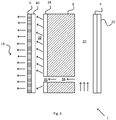
- Fig.1 shows a cross-sectional side view of a sound dampening device 1 according to an embodiment of the present invention.
- the sound dampening device 1 comprises a frame 2, a rear layer 4 and a front layer 6 arranged on opposite sides of the frame 2, such that the frame 2, the rear layer 4 and the front layer 6 forms an enclosed space.
- a first sound absorbing layer 8 is also arranged between the rear layer 4 and the front layer 6 wherein a cavity 10 is formed between the rear layer 4 and the first sound absorbing layer 8.
- An air purifying device 12 is arranged in fluid communication with the cavity 10, such that purified air from the air purifying device 12 is supplied to the cavity 10 via an inlet 14 and is discharged through at least one opening 16 in the first sound absorbing layer 8 and at least one output zone 18 in the front layer 6. Polluted air from the environment in which the sound dampening device 1 is arranged is entering the air purifying device 12 and is purified. The purified air is supplied to the cavity 10 through the inlet 14 and when the cavity 10 fills up with air a pressure builds up inside the cavity 10. The pressure inside the cavity 10 then becomes higher than the pressure in the surrounding layers. Air always choses to flow where there is less flow resistance.
- the air passes through the at least one opening 16 in the first sound absorbing layer 8 and is discharged through the at least one output zone 18 in the front layer 6.
- purified air is supplied in the vicinity of the sound dampening device 1 and a local environment with purified air is achieved.
- the first sound absorbing layer 8 and the cavity 10 cause the sound dampening device 1 to dampen sounds from the environment as well as from the air purifying device 12. This way is achieved a sound dampening device 1, which improves the indoor environment in multiple ways.
- a pure environment with good acoustic properties can improve people's comfort and health and may result in higher productivity.
- the frame 2 preferably comprises wooden beams arranged to form a rectangular frame. Alternatively the frame 2 has a square shape or any other shape.
- the frame 2 may comprise a lightweight material such as composites, aluminum, fiberglass, or similar.
- the front layer 6 has a weight per area unit of 150-350 g/m 2 which corresponds to a high permeability and low flow resistance.
- the front layer may comprise stitched polyester or any other fabric with the same low flow resistance and high permeability. This way, the front layer 6 causes a low flow resistance and the purified air is discharged through the front layer 6 with an optimal speed.
- the thickness of the front layer 6 is between 0,1-4 millimetres, preferably between 0,2-3 millimetres.
- the front layer 6 comprises an impermeable material with at least one port defining the at least one output zone 18.
- the rear layer 4 preferably comprises an impermeable material, preferably a wooden board, cardboard, fibre board or similar.
- the rear layer 4 may comprise a pressed polyester fibre or similar material with a weight per area unit of 1000-1500 g/m 2 . This weight per area unit corresponds to a low permeability and purified air will thus not pass through the rear layer 4.
- a second sound absorbing layer 20 is arranged on an outer side of the rear layer 4.
- the second sound absorbing layer 20 suitably consists of a fabric with a polyether foam coating.
- the density of the second sound absorbing layer is between 20-70 kg/m 3 , preferably between 35-60 kg/m 3 .
- the weight per unit area of the first sound absorbing layer 8 is preferably between 1000-1500 g/m 2 , which corresponds to a high flow resistance and thus low permeability. This way, the air choses to flow through the opening 16 in the sound absorbing layer 8, where the flow resistance is lower.
- the first sound absorbing layer 8 may comprise pressed polyester fibre.
- the first sound absorbing layer 8 may be a wadding of thermal bonded polyester fibre comprising a plurality of micro openings.
- the thickness of the first sound absorbing layer 8 is between 10-50 millimetres, preferably 13-20 millimetres.
- the first sound absorbing layer 8 is preferably arranged between the rear layer 4 and the front layer 6, such that it abuts the front layer 6 and the at least one opening 16 in the first sound absorbing layer 8 may have the shape of a rectangle.
- the at least one opening 16 may have a width between 80-120 centimetres and a height between 15-25 centimetres.
- the first sound absorbing layer 8 may comprise a plurality of openings 16 with a rectangular shape, a circular shape or any other shape. Due to lower air resistance, the purified air passes through the openings 16 in the first sound absorbing layer 8 and on through the front layer 6.
- the dimensions of the at least one output zone 18 of the front layer 6 corresponds to the dimensions of the at least one opening 16 in the first sound absorbing layer 8.
- the at least one output zone 18 may thus have a width between 80-120 centimetres and a height between 15-25 centimetres.
- a distribution layer 22 is arranged such that the purified air is discharged through the front layer 6 via the distribution layer 22.
- the distribution layer 22 may comprise a cellular plastic such as foam or a polyester resin, with an open cell structure and low density.
- the distribution layer 22 may comprise a material with a cell diameter of 2000 to 3500 micrometers.
- the open cell structure and the cell diameter of the distribution layer 22 results in a high permeability and low flow resistance and thus a limited pressure drop of the air flow when passing through the distribution layer 22.
- the distribution layer 22 and the first sound absorbing layer 8 are configured such that the flow resistance is lower and the permeability higher in the distribution layer 22 than in the first sound absorbing layer 8.
- the distribution layer 22 comprises air channels perpendicular to the extension of the front layer 6. The purified air is then led into the channels and flows in the direction towards the front layer 6. This way, the air flow at the output of the distribution layer 22 and at the at least one output zone 18 of the front layer 6, is directed substantially perpendicularly to the extension of the front layer 6. A substantially laminar air flow is thus achieved at the output of the distribution layer 22 and at the output of the front layer 6.
- the inlet 14 to the cavity 10 comprises an aperture in the front layer 6 and the air purifying device 12 is tightly arranged at the front layer 6.
- the air purifying device 12 comprises at least one filter unit 24 and a fan means 26.
- the at least one filter unit 24 preferably comprises a particle filter which is adapted to filter particles of 0,01 micrometers and larger. Alternatively the filter unit 24 filters particles of 0,005 micrometers and larger.
- the filter unit 24 may be a panel filter. This way, most viruses, bacteria, asbestos fibre, ash, diesel particles, oil smoke, cement powder, the majority of tobacco particles and coal smoke are filtered out.
- the filtrating surface is dimensioned in relation to the total capacity and the air flow.
- the fan means 26 comprises a motor and a rotating arrangement of vanes or blades (not shown) and the capacity (m 3 /h) of the fan means 26 is dimensioned to achieve a local zone of pure air for a person located in the vicinity of the sound dampening device 1.
- the fan means 26 is preferably configured with accurately designed blades and a suitable number of blades in relation to the rotation frequency in order to reduce the vibration and thus the noise from the fan means 26.
- the air purifying device 12 also comprises a housing 28 surrounding the fan means 26, which housing 28 fits tightly against the front layer 6 such that no air can enter the inlet 14 to the cavity 10 without having passed through the at least one filter unit 24.
- a pre-filter 30 is preferably arranged in front of (upstream) the at least one filter unit 24, such that the polluted air first passes the pre-filter 30 and then the at least one filter unit 24.
- the pre-filter 30 is suitably a polyester resin with an open cell structure.
- the pre-filter 30 may have a cell diameter of 1500-2500 micrometers.
- the air purifying device 12 may further comprise an activated carbon filter, an ionisation filter, catalytic filter, and/or an ultraviolet sterilization unit.
- the air purifying device 12 preferably reduces the particle content of particles larger than 0,005 micrometers in the air by 70-99,9 % and filtrates between 20-300 m 3 air per hour.
- the fan means 26 When the fan means 26 sucks in air (shown as arrows in the figure) from the surroundings it first passes the pre-filter 30 and it then passes through the at least one filter unit 24. The fan means 26 subsequently feeds the air into the cavity 10 and a pressure builds up inside the cavity 10, which pressure is higher than the pressure in the adjacent distribution layer 22. Since the rear layer 4 is impermeable and the distribution layer 22 is permeable the air flows through the distribution layer 22. Due to the porosity and thus the flow resistance of the distribution layer 22, the air flow is distributed throughout the distribution layer 22. Since the first sound absorbing layer 8 has a higher density and is less permeable than the distribution layer 22, the air chooses to flow through the distribution layer 22 arranged in the opening 16 of the first sound absorbing layer 8.
- the air is then discharged through an at least one output zone 18 in the front layer 6. Due to the low permeability of the first sound absorbing layer 8, the at least one output zone 18 corresponds to the opening16 in the first sound absorbing layer 8, through which the air is flowing. This way, the flow area through which the purified air is discharged is larger than the cross sectional area of the cavity 10 and a substantially even distribution of purified air is achieved over a larger area.
- the sound dampening device 1 may be attached on furniture, be integrated with furniture or be a separate unit arranged on walls, roofs or floor. This way, furniture with an integrated air purifying system for the local environment of the user of the furniture may be achieved. This type of furniture also has a positive effect on the noise level in a room.
- the sound dampening device 1 may constitute a module, such that several different sound dampening devices 1 may be arranged in fluid communication between their respective cavities 10. This modularity allows for the construction of the system capacity, in order to increase the surface with sound absorbing properties and flow area and air volume up to the desired levels. All the layers and components in the sound dampening device 1 may consist of recyclable material or natural fibre.
- Fig.2 shows a cross-sectional side view of a sound dampening device 1 according to an embodiment of the present invention.
- the sound dampening device 1 is configured as the sound dampening device 1 in fig. 1 , with the exception that the distribution layer 22 is arranged only in the opening 16 of the first sound absorbing layer 8.
- the function of the sound dampening device 1 in fig. 2 and all other features are the same as described in relation to fig. 1 .
- Fig. 3 a shows a front view of the sound dampening device 1 according to fig.1 or fig. 2 .
- the inlet 14 to the cavity 10 and thus the air purifying device 12 is elongated and extends in the direction of the width of the sound dampening device 1. This way, a large air volume can be supplied to the cavity 10 without the need of operating the fan means 26 at high power. Also, by using an elongated filter unit 24 the filtrating area is increased which results in an improved filtering capacity.
- the at least one output zone 18 of the front layer 6 is shown with dotted lines.
- a regulating means 32 for regulating the air flow from the air purifying device 12 is arranged on an outer side of the front layer 6.
- the regulating means 32 may be a switch, lever, button, knob or similar and regulates the speed of the motor of the fan means 26.
- the motor may preferably work at different speeds and the lower the speed the less noise is generated.
- a variable speed control of the fan means 26 motor is provided.
- the fan means 26 motor operates at three different speeds, a low speed, a medium speed and a high speed.
- a low speed may be defined as a speed lower than 650 rpm
- a medium speed may be defined as a speed between 650-950 rpm
- a high speed may be defined as a speed between 950-1310 rpm. Since the main object of the sound dampening device 1 is to improve the local environment there is no need for a very powerful and expensive fan means 26.
- the sound dampening device may have a noise level under 40 dB(A), preferably under 30 dB(A), and a power consumption between 20-70 W, depending on the speed of the fan means 26 motor (not shown).
- the motor speed By regulating the motor speed in combination with the porosity/permeability of the distribution layer 22 and/or the front layer 6, the purified air which is discharged through the front layer 6 has a flow rate between 0,1-0,5 m/s. This way draught is avoided and an optimal local environment with purified air is achieved.
- Fig. 3b shows a cross-sectional front view of the sound dampening device 1 according to fig.1 , fig. 2 or fig. 3a .
- the frame 2 surrounds the first sound absorbing layer 8 and in the opening 16 of the first sound absorbing layer 8 the distribution layer 22 can be seen.
- the front layer 6 covers the front of the sound dampening device 1, which here is illustrated with only a portion of the front layer 6.
- Fig. 4 shows a cross-sectional view of a sound dampening device 1 according to an embodiment of the invention.
- the sound dampening device 1 comprises a frame 2 (not shown), a rear layer 4 and a front layer 6 arranged on opposite sides of the frame 2, such that the frame 2, the rear layer 4 and the front layer 6 forms an enclosed space.
- a first sound absorbing layer 8 is also arranged between the rear layer 4 and the front layer 6 wherein a cavity 10 is formed between the rear layer 4 and the first sound absorbing layer 8.
- An air purifying device 12 is arranged in fluid communication with the cavity 10, such that purified air from the air purifying device 12 is supplied to the cavity 10 via an inlet 14 and is discharged through at least one opening 16 in the first sound absorbing layer 8 and at least one output zone 18 in the front layer 6.
- the density of the front layer 6 is between 20-50 kg/m 3 , preferably between 30-40 kg/m 3 . This way, the front layer 6 causes a low air resistance and the purified air is discharged through the front layer 6 with an optimal speed.
- the front layer 6 may comprise a fabric with low air resistance.
- the front layer 6 may comprise a fabric with a polyether foam coating.
- the thickness of the front layer 6 is between 2-10 millimetres, preferably between 4-8 millimetres.
- the rear layer 4 preferably comprises an impermeable material, preferably a wooden board, cardboard, fibre board or similar.
- a second sound absorbing layer 20 is arranged on an outer side of the rear layer 4.
- the first sound absorbing layer 8 may consists of a resistive sound absorber. It may be a wadding of thermal bonded polyester fibre with a thickness between 10-50 millimetres. The weight per unit area of the first sound absorbing layer 8 is between 1000-1500 g/m 2 .
- the at least one opening 16 in the first sound absorbing layer 8 may have the shape of a rectangle or any other shape. Due to lower flow resistance, the purified air passes through the opening 16 in the first sound absorbing layer 8.
- a first membrane 34 is arranged between the first sound absorbing layer 8 and the front layer 6, such that it abuts the first sound absorbing layer 8.
- the first membrane 34 comprises an opening 36, corresponding to the opening 16 in the first sound absorbing layer 8.
- the first membrane 34 preferably consists of a material which is air impermeable and has mechanical features which does not hinder the transfer of sound to the first sound absorbing layer 8.
- the first membrane 34 may for example be a completely airtight polyamide coated with polyurethane, with a weight of 600 g/m 2 .
- An air distribution chamber 38 is formed between the first membrane 34 and the front layer 6, which chamber 38 acts sound dampening.
- the purified air passes through the opening 16 in the first sound absorbing layer 8 and the opening 36 in the first membrane 34 and fills the chamber 38.
- a distance material with a very open structure may be arranged in the distribution chamber 38, which enables distribution of pure air with limited pressure drop.
- the distance material may be a three-dimensional polyester fabric with a thickness between 10 to 30 millimetres, a very low density and low weight per cubic metre (10-20 kg).
- a second perforated membrane 40 is arranged between the front layer 6 and the chamber 38, such that the purified air passes through the perforated membrane 40 and on through the front layer 6.
- the dimensioning of the number of holes and the sizes of the holes per unit of area in the membrane 40 is inversely proportional to the pressure gradient at the inlet into the chamber 38, in order to distribute the air flow evenly over the front layer 6.
- the perforation comprises more holes further away from the fan means 26 of the air purifying device 12.
- the perforation pattern of the membrane 40 may for example comprise between 2000 to 4000 holes/m 2 with a diameter between 3 to 10 millimetres.
- the air purifying device 12 comprises at least one filter unit 24 and a fan means 26 which are configured and functions as described in relation to fig. 1 .
- Structural components, sound absorbers and air channels are configured to dampen the sound frequencies that are generated from the fan means 26 and from the air flow itself in an efficient way.
- the capacity (m 3 /h) of the fan means 26 is dimensioned after the at least one output zone 18 in the front layer, the at least one filter unit 24 and the requested volume of purified air in relation to the number of persons and the air volume indoors, amongst other parameters.
- the fan means 26 feeds the purified air into the cavity 10 and a pressure builds up inside the cavity 10. Since the rear layer 4 is impermeable the air flows through the opening 16 in the first sound absorbing layer 8 and the opening 36 in the first membrane 34 to the air distribution chamber 38. The air is then distributed over the perforated membrane 40 and is discharged through the at least one output zone 18 in the front layer 6.
- the permeability of the different components and the distribution of air pressure mean that the pressure of the air discharged through the front layer 6 is lower than the pressure in the distribution chamber 38, which is lower than the air pressure in the opening 16 in the first sound absorbing layer 8. This way, the flow area through which the purified air is discharged is larger than the cross sectional area of the cavity and a substantially even distribution of purified air is achieved over a larger area.
- the sound dampening device 1 may be attached on furniture, be integrated with furniture or be a separate unit arranged on walls, roofs or floor.
- the sound dampening device 1 may constitute a module, such that several different sound dampening devices may be arranged in fluid communication between their respective cavities. This modularity allows for the construction of the system capacity, in order to increase the surface with sound absorbing properties and flow area and air volume up to the desired levels. All the layers and components in the sound dampening device 1 may consist of recyclable material or natural fibre.
- Fig. 5 shows a side view of a sound dampening device 1 according to fig.1 , fig. 2 or fig. 4 , where the sound dampening device 1 constitutes an acoustic screen, partition wall or similar.
- the sound dampening device 1 is thus arranged at a desk 42, such that the air purifying device is positioned under the desktop 44.
- the sound dampening device 1 constituting an acoustic screen may have a width of 800-2200 millimetres and a height of 600-1000 millimetres.
- the thickness of the sound dampening device 1 may be 30-60 millimetres.
- the sound dampening device 1 is preferably arranged, such that the lower edge of the at least one output zone 18 of the front layer 6 is positioned 10-25 centimeters above the desktop 44.
- the different layers and/or membranes are configured such that the purified air is discharged through the front layer 6 at a level corresponding substantially to the level of a person's head.
- Fig. 6a shows a cross-sectional side view of a sound dampening device 1 according to fig. 1 , with the addition of an air permeable padded layer 45 arranged on an outer side of the front layer 6, above the aperture in the front layer 6 and the air purifying device 12.
- the padded layer 45 may comprise a cellular plastic such as foam or a polyester resin, with an open cell structure and low density.
- the padded layer 45 may comprise a material with a cell diameter between 1500 to 2500 micrometers. The open cell structure and the cell diameter results in a high permeability/porosity and the padded layer 45 barely affects the flow rate of the purified air.
- the padded layer 45 may comprise any other material with equivalent properties relating to resistance and permeability.
- the thickness of the padded layer 45 may be 20-50 millimetres.
- the padded layer 45 may consist of wadding covered by a fabric with high permeability. The purified air is thus discharged through the distribution layer 22, the at least one opening 16 in the first sound absorbing layer 8, the front layer 6 and finally the padded layer 45.
- the area of the padded layer 45 where purified air is discharged corresponds to the at least one output zone 18 of the front layer 6.
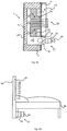
- Fig. 6b shows a side view of a headboard device 48 comprising a frame 2, a rear layer 4 and a front layer 6 arranged on opposite sides of the frame 2, such that the frame 2, the rear layer 4 and the front layer 6 forms an enclosed space, wherein a first intermediate layer 8 is arranged between the rear layer 4 and the front layer 6.
- a cavity 10 is formed between the rear layer 4 and the intermediate layer 8 and an air purifying device 12 is arranged in fluid communication with said cavity 10, such that purified air from the air purifying device 12 is supplied to the cavity 10 via an inlet 14 and is discharged through at least one opening 16 in the intermediate layer 8 and at least one output zone 18 in the front layer 6.
- the first intermediate layer 8 is preferably a sound absorbing layer.
- An air permeable distribution layer 22 is arranged in the at least one opening 16 in the intermediate layer 8, such that the purified air is discharged through the front layer 6 via the distribution layer 22.
- the distribution layer 22 comprises air channels perpendicular to the extension of the front layer 6.
- the air purifying device 12 comprises at least one filter unit 24 and fan means 26.
- An air permeable padded layer 45 as disclosed in fig. 6b is preferably arranged on an outer side of the front layer 6.
- a regulating means 32 for regulating the air flow from the air purifying device 12 is also arranged on an outer side of the front layer 6.
- a second sound absorbing layer 20 is preferably arranged at an outer side of the rear layer 4.
- the headboard device 48 comprises a sound dampening device 1 as previously disclosed in fig. 1-4 or 6a .
- the headboard device 48 is arranged by a bed 46, such that the air purifying device 12 is positioned under the bed 46 and the at least one output zone 18 is positioned above the bed 46.
- the sound from the air purifying device 12 is thus further dampened by the bed 46.
- Cold air is heavier than warm air and the air at the floor level in a room is thus colder than the air on a higher level in the room.
- the difference of temperature in a room may vary between 0,2-2 degrees between different levels.
- the at least one opening 16 in the first sound absorbing layer 8 and thus the at least one output zone 18 (here shown with dotted lines) in the front layer 6 is preferably configured such that purified air is discharged over 70-90 % of the total area of the padded layer 45.
- Purified air is preferably discharged from the headboard 48 adjacent the mattress of the bed 46. This way purified air is discharged close to the persons head laying in the bed 46, and a local environment with purified air is achieved.
- the headboard device 48 such that purified air may be discharged over a large area, enough purified airflow is achieved even in the case where part of the output zone 18 is covered by for example a pillow or a person.
- the air purifying device 12 preferably comprises a pre-filter 30 arranged in front of the at least one filter unit 24.
- the pre-filter 30 preferably comprises a screen, to prevent dust and dirt from entering the at least one filter unit 24.
- the pre-filter 30 suitably comprises a polyester resin with an open cell structure.
- the pre-filter 30 may comprise a material with a cell diameter of 1500-2500 micrometers.
- the headboard device 48 may thus generate a noise level under 30 dB(A), preferably under 25 dB(A).
- the headboard device 48 may also comprise speakers, lightening, compartments or shelves and/or electrical sockets integrated in the headboard device 48. This way is achieved a functional headboard device 48, which is sound dampening and provides a pure local environment. Good air quality in a bedroom may improve the sleep and may thus improve people's health.
- the headboard device 48 may have a width of 700-2200 millimetres and a height of 900-1300 millimetres.
- the thickness of the headboard device 48 may be 30-250 millimetres.
Description
- The present invention relates to a sound dampening device. The invention may be attributed to the manufacturing industry of sound dampening devices.
- Various devices are today used to improve the indoor environment in for example offices, public buildings, schools, hospitals and exhibition areas or similar. The indoor environment may affect peoples' health, their quality of life, comfort, ability to learn and productivity. This is specifically a fact in colder climates where people tend to spend more time indoors. Factors that may affect the indoor environment are air quality, thermal comfort, acoustic properties and the visual quality.
- Poor acoustic properties in an indoor environment may specifically affect people's cognitive and communicative abilities. Consequences of poor acoustic environments may be attention problems, concentration problems, reduced ability to learn, lower quality of performed work and lower productivity. At higher sound levels there might also be a risk of temporary or permanent hearing impairment, tinnitus, health problems and stress.
- The indoor air quality may also affect people's health. Air pollutants, particles, allergens, humidity, mould, bacteria and virus are examples of elements that may be a health hazard. Poor air quality may cause asthma, allergies, symptoms in the eyes, the nose and on the skin, fatigue and headache. Such symptoms will, naturally, also have an impact on cognitive and communicative abilities.
- Various devices are often used to each solve a separate problem relating to the indoor environment. In order to improve the acoustic properties in a room acoustic screens, panels and sound dampening partition walls may be used. Ventilation and air conditioning units may be used to improve the thermal comfort and air purifiers may be used to improve the air quality. While these devices solve one problem, they may cause another problem. For example, a separate air purifier might be visually disturbing and cause unpleasant air flows, draught, high noise levels and might even be standing in the way. Some sound absorbing solutions may also cause problems, such as hindering ventilation and collecting of dust, particles and microorganisms. Also, in order to improve the air quality in a whole room, an air purifier needs to purify a large air volume and thus is needed a powerful fan.
- There are some examples of solutions which try to combine several functions in order to improve the indoor environment. Document
EP0380660 describes a radiation air-conditioner in the form of a partition wall, which can be freely moved in order to handle the problem with unevenly distributed heat loads in a closed office. The air-conditioner comprises a panel with a plurality of thermoelectric elements and heat exchanger means and fan means installed inside the panel. This is however a complex and costly solution which complicates maintenance and service of the air-conditioner. - Document
SE533460 - Document
GB667055 A US5830058 A discloses a ventilation installation mounted to a ceiling. DocumentUS2004/009746 A1 discloses a canopy air delivery system and documentUS3724172 discloses a filtered air breathing zone. - Despite known solutions in the area there is a need to further develop a simple, cost-effective solution for improving the indoor environment.
- The object of the present invention is to provide a sound dampening device, which improves the indoor environment in multiple ways.
- A further object of the invention is to provide a sound dampening device, which achieves a local environment with purified air.
- Yet another object of the invention is to provide a sound dampening device, which is cost-effective.
- These objects are achieved by the sound dampening device of the initially mentioned kind, which is characterized by the features specified in the characterizing part of
claim 1. - The sound dampening device according to the invention comprises a frame, a rear layer and a front layer arranged on opposite sides of the frame, such that the frame, the rear layer and the front layer forms an enclosed space. A first sound absorbing layer is also arranged between the rear layer and the front layer wherein a cavity is formed between the rear layer and the first sound absorbing layer. By arranging an air purifying device in fluid communication with the cavity, such that purified air from the air purifying device is supplied to the cavity via an inlet and is discharged through at least one opening in the first sound absorbing layer and at least one output zone in the front layer, an air purifying function integrated with a sound dampening function is achieved. Both the sound absorbing layer and the cavity dampen sounds from the environment as well as from the air purifying device, which results in a very efficient sound dampening. By discharging purified air through the front layer pure air is discharged where it is actually needed and a local environment with purified air is achieved. This is very difficult to achieve with common air purifiers for purifying a whole room, where a very large air volume needs to be purified. Also, by focusing on improving the local environment a smaller air volume needs to be purified and the capacity of the air purifying device can be minimized, which results in a cost-effective air purifying sound dampening device.
- According to the invention an air permeable distribution layer is arranged in the at least one opening in the first sound absorbing layer, such that the purified air is discharged through the front layer via the distribution layer. The material of the first sound absorbing layer and the material of the distribution layer are configured such that the permeability is higher and the flow resistance is lower in the distribution layer than in the first sound absorbing layer.
- In an alternative not claimed by the current invention, the distribution layer is arranged between the cavity and the first sound absorbing layer. The distribution layer may also be arranged between the cavity and the first sound absorbing layer as well as in the at least one opening in the first sound absorbing layer. Air always choses the way with less flow resistance and the distribution layer and the rear layer are configured such that the flow resistance in the distribution layer is less than in the rear layer. This way, when purified air is supplied to the cavity and a pressure builds up inside the cavity, the purified air is distributed throughout the distribution layer and is discharged through the at least one output zone in the front layer.
- The distribution layer may comprise a cellular plastic, such as foam or a polyester resin, with an open cell structure and low density. A cellular plastic is a type of plastic containing numerous cells or pores disposed uniformly throughout its mass. An open cell structure means that the cells are connected to each other, which make the material soft, light and airy. A closed cell structure means that each cell is completely surrounded by a solid material and the cells are thus separated from each other. A material with an open cell structure typically has a higher permeability than a material with a closed cell structure. The distribution layer may comprise a material with a cell diameter between 2000 to 3500 micrometers. The open cell structure and the cell diameter results in a high permeability/porosity of the distribution layer, which causes a low flow resistance and thus a limited pressure drop of the airflow when passing through the distribution layer. The flow resistance and the pressure drop cause the purified air to spread and to be distributed within and throughout the distribution layer. This way, the flow area through which the purified air is discharged is larger than the cross sectional area of the inlet to the cavity and a substantially even distribution of purified air is achieved over a larger area. By having a larger outlet area than inlet area, the purified air is discharged with a lower flow rate than when supplied to the cavity through the inlet. A low flow rate is advantageous in that draught is avoided and a comfortable local environment with purified air is achieved. The low flow resistance in the distribution layer also means that the air purifying device can operate with low power and still achieve the desired flow rate, which minimizes the vibrations and noise from the air purifying device itself. The distribution layer may comprise any other material with equivalent properties relating to resistance and permeability. The thickness of the distribution layer may be 10-25 millimetres.
- Permeability is defined as a measure of the ability of a material to transmit fluids at a certain loss of pressure. High permeability means that a larger volume of fluid may be transmitted per square meter of the material and unit of time.
- According to an aspect of the invention, the distribution layer comprises air channels perpendicular to the extension of the front layer. The purified air is led into the channels and flows in the direction towards the front layer. This way, the air flow at the output of the distribution layer and at the at least one output zone of the front layer, is directed substantially perpendicularly to the extension of the front layer. A substantially laminar air flow is thus achieved at the output of the distribution layer and at the output of the front layer.
- According to an aspect of the invention, the front layer has a weight per area unit of 150-350 g/m2. This relatively low weight corresponds to a high permeability and low flow resistance. The front layer may comprise stitched polyester or any other fabric with the same high permeability and low flow resistance. This way, the front layer causes a low resistance and the purified air is discharged through the front layer with an optimal low speed. The front layer may have a thickness of 0,2-3 millimetres.
- According to an aspect of the invention, the first sound absorbing layer preferably has a weight per area unit of 1000-1500 g/m2. This relatively high weight corresponds to a low permeability and high flow resistance. The first sound absorbing layer and the distribution layer are configured such that the permeability is higher and the flow resistance is lower in the distribution layer than in the first sound absorbing layer. This way, the air choses to flow through the opening in the sound absorbing layer and/or the distribution layer, where the permeability is higher. The first sound absorbing layer may comprise pressed polyester fibre. The thickness of the first sound absorbing layer is between 10-50 millimetres, preferably 13-20 millimetres.
- According to an aspect of the invention, the air purifying device comprises at least one filter unit and fan means. The air purifying device preferably comprises a housing inside which the fan means is arranged and the at least one filter unit is arranged at the inlet of the housing, such that polluted air from the surroundings first enter the at least one filter unit by suction of the fan means and is subsequently supplied to the cavity by the fan means. The fan means comprises a motor and a rotating arrangement of vanes or blades.
- The inlet to the cavity preferably comprises an aperture in the front layer. The air purifying device is then suitably tightly arranged at the front layer, such that it covers the aperture. The air purifying device is preferably arranged such that the housing covers the aperture in the front layer and such that the fan means is arranged in the inlet to the cavity. Alternatively, the inlet to the cavity comprises an aperture in the rear layer or the frame. Thus, the air purifying device may be tightly arranged at the rear layer or at the frame respectively. Since the air purifying device preferably is arranged on the outer side of the front layer, rear layer or the frame, a sound dampening device is achieved, which facilitates maintenance and service.
- According to an aspect of the invention, a second sound absorbing layer is arranged at an outer side of the rear layer. The second sound absorbing layer suitably consists of a fabric with a polyether foam coating. This way, the sound dampening function of the sound dampening device is improved.
- According to an aspect of the invention, an air permeable padded layer is arranged on the outer side of the front layer. Alternatively an air permeable padded layer is arranged between the first sound absorbing layer and the front layer. This way, the sound dampening device is soft and comfortable to leans against. The padded layer may comprise a cellular plastic, such as foam or a polyester resin, with an open cell structure and low density. The padded layer may comprise a material with a cell diameter between 1500 to 2500 micrometers. The open cell structure and the cell diameter results in a high permeability/porosity and the padded layer barely affects the flow rate of the purified air. The padded layer may comprise any other material with equivalent properties relating to flow resistance and permeability. The thickness of the padded layer may be 20-50 millimetres.
- According to an aspect of the invention a regulating means for regulating the air flow from the air purifying device is arranged on an outer side of the front layer. Alternatively the regulating means is arranged on an outer side of the frame or the rear layer. The user of the sound dampening device may thereby regulate the air flow being discharged through the front layer and the user can also completely turn off the air purifying device. This way is achieved a flexible and user-friendly sound dampening device.
- The rear layer preferably comprises an impermeable material, preferably a wooden board, cardboard, fibre board or similar. Alternatively, the rear layer may comprise a pressed polyester fibre or similar material with a weight per area unit of 1000-1500 g/m2. This weight corresponds to a low permeability and purified air will thus not pass through the rear layer.
- According to an aspect of the invention the sound dampening device constitutes a partition wall or an acoustic screen. The sound dampening device is then preferably arranged on a desk or by a desk, in for example an office. The sound dampening device is preferably arranged such that the air purifying device is positioned under the desktop. This way, the sound from the air purifying device is further dampened by the desktop. When arranged at a desk, the at least one output zone in the front layer is arranged substantially at the level/height of the head of a person sitting or standing at the desk. This way, the purified air is discharged in the vicinity of the persons face and a good and healthy air quality is achieved in the person's local environment. The sound dampening device constituting an acoustic screen may have a width of 800-2200 millimetres and a height of 600-1000 millimetres. The thickness of the sound dampening device may be 30-60 millimetres.
- According to an aspect of the invention the sound dampening device comprises an air cooling device. By cooling the air before discharge through the front layer the air gets heavier and this way is controlled that the discharged air falls downwards rather than rises upwards. This ensures that the purified air is collected where it does the most good.
- These objects are also achieved by the headboard device comprising the sound dampening according to
claim 12 and the headboard device according to claim 13. - According to an aspect of the invention the headboard device comprises a frame, a rear layer and a front layer arranged on opposite sides of the frame, such that the frame, the rear layer and the front layer forms an enclosed space, wherein a first intermediate layer is arranged between the rear layer and the front layer. A cavity is formed between the rear layer and the intermediate layer and an air purifying device is arranged in fluid communication with said cavity, such that purified air from the air purifying device is supplied to the cavity via an inlet and is discharged through at least one opening in the intermediate layer and at least one output zone in the front layer. This way is achieved a headboard which purifies air and thus creates a local environment with purified air. According to an aspect of the invention, the first intermediate layer is a sound absorbing layer. This way is achieved a headboard with an integrated air purifying function and a sound dampening function.
- Preferably, an air permeable distribution layer is arranged in the at least one opening in the intermediate layer, such that the purified air is discharged through the front layer via the distribution layer. The distribution layer may comprise air channels perpendicular to the extension of the front layer.
- The air purifying device of the headboard device preferably comprises at least one filter unit and fan means.
- According to an aspect of the invention an air permeable padded layer is arranged on an outer side of the front layer of the headboard device.
- Preferably, a regulating means for regulating the air flow from the air purifying device is arranged on an outer side of the front layer of the headboard device.
- The headboard device is preferably arranged by the end of a bed or next to a bed such that the air purifying device is positioned under the bed. The sound from the air purifying device is thus further dampened by the bed. Cold air is heavier than warm air and the air at the floor level in a room is thus colder than the air on a higher level in the room. The difference of temperature in a room may vary between 0,2-2 degrees between different levels. By arranging the headboard device with the air purifying device close to the floor under the bed, colder air will enter the headboard device. When the purified air is discharged from the headboard device it will fall downwards since it is colder than the surrounding air at the same level and thus has a higher density. This way the natural temperature difference in a room is taken advantage of and it is ensured that the purified air is supplied and stays in the vicinity of the person lying on the bed.
- The headboard device may have a width of 700-2200 millimetres and a height of 900-1300 millimetres. The thickness of the headboard device may be 30-250 millimetres.
- The headboard may also comprise speakers, sockets for mobile phone chargers, compartments, shelves and/or lightening integrated into the sound dampening device. This way is achieved a functional headboard, which is sound dampening and provides a pure local environment. Good air quality in a bedroom may improve the sleep and thus improves people's health.
- Further advantages of the invention appear from the following detailed description.
- In the following, examples of the invention are described with reference to the accompanying drawings, in which:
- Fig. 1
- shows a cross-sectional side view of a sound dampening device according to an embodiment of the present invention,
- Fig. 2
- shows a cross-sectional side view of a sound dampening device according to another embodiment of the present invention,
- Fig. 3a
- shows a front view of a sound dampening device according to
fig. 1 orfig. 2 , - Fig. 3b
- shows a cross-sectional front view of a sound dampening device according to
fig.1 orfig. 2 , - Fig. 4
- shows a cross-sectional view of a sound dampening device according to an embodiment of the present invention,
- Fig. 5
- shows a side view of a sound dampening device according to
fig.1 ,fig. 2 orfig. 4 constituting an acoustic screen, - Fig. 6a
- shows a cross-sectional side view of a sound dampening device according to an embodiment of the present invention, and
- Fig. 6b
- shows a side view of a headboard configured according to the sound dampening device in
fig.1 ,fig. 2 ,fig. 4 offig. 6b . - The present invention will now be described as embodiments. For clarity, the components irrelevant to the invention have been omitted in the drawing. The same details as shown in several drawings may sometimes lack reference numerals, but correspond to those with reference numerals.
-
Fig.1 shows a cross-sectional side view of asound dampening device 1 according to an embodiment of the present invention. Thesound dampening device 1 comprises aframe 2, arear layer 4 and afront layer 6 arranged on opposite sides of theframe 2, such that theframe 2, therear layer 4 and thefront layer 6 forms an enclosed space. A firstsound absorbing layer 8 is also arranged between therear layer 4 and thefront layer 6 wherein acavity 10 is formed between therear layer 4 and the firstsound absorbing layer 8. Anair purifying device 12 is arranged in fluid communication with thecavity 10, such that purified air from theair purifying device 12 is supplied to thecavity 10 via aninlet 14 and is discharged through at least oneopening 16 in the firstsound absorbing layer 8 and at least oneoutput zone 18 in thefront layer 6. Polluted air from the environment in which thesound dampening device 1 is arranged is entering theair purifying device 12 and is purified. The purified air is supplied to thecavity 10 through theinlet 14 and when thecavity 10 fills up with air a pressure builds up inside thecavity 10. The pressure inside thecavity 10 then becomes higher than the pressure in the surrounding layers. Air always choses to flow where there is less flow resistance. In the disclosed embodiment, due to the permeability and thus flow resistance of therear layer 4 and the firstsound absorbing layer 8, the air passes through the at least oneopening 16 in the firstsound absorbing layer 8 and is discharged through the at least oneoutput zone 18 in thefront layer 6. This way, purified air is supplied in the vicinity of thesound dampening device 1 and a local environment with purified air is achieved. Also, the firstsound absorbing layer 8 and thecavity 10 cause thesound dampening device 1 to dampen sounds from the environment as well as from theair purifying device 12. This way is achieved asound dampening device 1, which improves the indoor environment in multiple ways. A pure environment with good acoustic properties can improve people's comfort and health and may result in higher productivity. - The
frame 2 preferably comprises wooden beams arranged to form a rectangular frame. Alternatively theframe 2 has a square shape or any other shape. Theframe 2 may comprise a lightweight material such as composites, aluminum, fiberglass, or similar. - The
front layer 6 has a weight per area unit of 150-350 g/m2 which corresponds to a high permeability and low flow resistance. The front layer may comprise stitched polyester or any other fabric with the same low flow resistance and high permeability. This way, thefront layer 6 causes a low flow resistance and the purified air is discharged through thefront layer 6 with an optimal speed. The thickness of thefront layer 6 is between 0,1-4 millimetres, preferably between 0,2-3 millimetres. Alternatively, thefront layer 6 comprises an impermeable material with at least one port defining the at least oneoutput zone 18. - The
rear layer 4 preferably comprises an impermeable material, preferably a wooden board, cardboard, fibre board or similar. Alternatively, therear layer 4 may comprise a pressed polyester fibre or similar material with a weight per area unit of 1000-1500 g/m2. This weight per area unit corresponds to a low permeability and purified air will thus not pass through therear layer 4. On an outer side of therear layer 4, a secondsound absorbing layer 20 is arranged. The secondsound absorbing layer 20 suitably consists of a fabric with a polyether foam coating. The density of the second sound absorbing layer is between 20-70 kg/m3, preferably between 35-60 kg/m3. - The weight per unit area of the first
sound absorbing layer 8 is preferably between 1000-1500 g/m2, which corresponds to a high flow resistance and thus low permeability. This way, the air choses to flow through theopening 16 in thesound absorbing layer 8, where the flow resistance is lower. The firstsound absorbing layer 8 may comprise pressed polyester fibre. The firstsound absorbing layer 8 may be a wadding of thermal bonded polyester fibre comprising a plurality of micro openings. The thickness of the firstsound absorbing layer 8 is between 10-50 millimetres, preferably 13-20 millimetres. The firstsound absorbing layer 8 is preferably arranged between therear layer 4 and thefront layer 6, such that it abuts thefront layer 6 and the at least oneopening 16 in the firstsound absorbing layer 8 may have the shape of a rectangle. The at least oneopening 16 may have a width between 80-120 centimetres and a height between 15-25 centimetres. Alternatively, the firstsound absorbing layer 8 may comprise a plurality ofopenings 16 with a rectangular shape, a circular shape or any other shape. Due to lower air resistance, the purified air passes through theopenings 16 in the firstsound absorbing layer 8 and on through thefront layer 6. The dimensions of the at least oneoutput zone 18 of thefront layer 6 corresponds to the dimensions of the at least oneopening 16 in the firstsound absorbing layer 8. The at least oneoutput zone 18 may thus have a width between 80-120 centimetres and a height between 15-25 centimetres. - Between the
cavity 10 and the firstsound absorbing layer 8, as well as in theopening 16 of the firstsound absorbing layer 8, adistribution layer 22 is arranged such that the purified air is discharged through thefront layer 6 via thedistribution layer 22. Thedistribution layer 22 may comprise a cellular plastic such as foam or a polyester resin, with an open cell structure and low density. Thedistribution layer 22 may comprise a material with a cell diameter of 2000 to 3500 micrometers. The open cell structure and the cell diameter of thedistribution layer 22 results in a high permeability and low flow resistance and thus a limited pressure drop of the air flow when passing through thedistribution layer 22. Thedistribution layer 22 and the firstsound absorbing layer 8 are configured such that the flow resistance is lower and the permeability higher in thedistribution layer 22 than in the firstsound absorbing layer 8. This way, the purified air choses to flow through thedistribution layer 22. The flow resistance and the pressure drop cause the purified air to spread and to be distributed within and throughout thedistribution layer 22. The low flow resistance also means that theair purifying device 12 may operate with low power and still achieve the desired flow rate, which minimizes the vibrations and noise from theair purifying device 12 itself. The thickness of thedistribution layer 22 may be 10-25 millimetres. According to an aspect of the invention, thedistribution layer 22 comprises air channels perpendicular to the extension of thefront layer 6. The purified air is then led into the channels and flows in the direction towards thefront layer 6. This way, the air flow at the output of thedistribution layer 22 and at the at least oneoutput zone 18 of thefront layer 6, is directed substantially perpendicularly to the extension of thefront layer 6. A substantially laminar air flow is thus achieved at the output of thedistribution layer 22 and at the output of thefront layer 6. - The
inlet 14 to thecavity 10 comprises an aperture in thefront layer 6 and theair purifying device 12 is tightly arranged at thefront layer 6. Theair purifying device 12 comprises at least onefilter unit 24 and a fan means 26. The at least onefilter unit 24 preferably comprises a particle filter which is adapted to filter particles of 0,01 micrometers and larger. Alternatively thefilter unit 24 filters particles of 0,005 micrometers and larger. Thefilter unit 24 may be a panel filter. This way, most viruses, bacteria, asbestos fibre, ash, diesel particles, oil smoke, cement powder, the majority of tobacco particles and coal smoke are filtered out. The filtrating surface is dimensioned in relation to the total capacity and the air flow. The fan means 26 comprises a motor and a rotating arrangement of vanes or blades (not shown) and the capacity (m3/h) of the fan means 26 is dimensioned to achieve a local zone of pure air for a person located in the vicinity of thesound dampening device 1. The fan means 26 is preferably configured with accurately designed blades and a suitable number of blades in relation to the rotation frequency in order to reduce the vibration and thus the noise from the fan means 26. Theair purifying device 12 also comprises ahousing 28 surrounding the fan means 26, whichhousing 28 fits tightly against thefront layer 6 such that no air can enter theinlet 14 to thecavity 10 without having passed through the at least onefilter unit 24. A pre-filter 30 is preferably arranged in front of (upstream) the at least onefilter unit 24, such that the polluted air first passes the pre-filter 30 and then the at least onefilter unit 24. The pre-filter 30 is suitably a polyester resin with an open cell structure. The pre-filter 30 may have a cell diameter of 1500-2500 micrometers. Theair purifying device 12 may further comprise an activated carbon filter, an ionisation filter, catalytic filter, and/or an ultraviolet sterilization unit. Theair purifying device 12 preferably reduces the particle content of particles larger than 0,005 micrometers in the air by 70-99,9 % and filtrates between 20-300 m3 air per hour. - When the fan means 26 sucks in air (shown as arrows in the figure) from the surroundings it first passes the pre-filter 30 and it then passes through the at least one
filter unit 24. The fan means 26 subsequently feeds the air into thecavity 10 and a pressure builds up inside thecavity 10, which pressure is higher than the pressure in theadjacent distribution layer 22. Since therear layer 4 is impermeable and thedistribution layer 22 is permeable the air flows through thedistribution layer 22. Due to the porosity and thus the flow resistance of thedistribution layer 22, the air flow is distributed throughout thedistribution layer 22. Since the firstsound absorbing layer 8 has a higher density and is less permeable than thedistribution layer 22, the air chooses to flow through thedistribution layer 22 arranged in theopening 16 of the firstsound absorbing layer 8. The air is then discharged through an at least oneoutput zone 18 in thefront layer 6. Due to the low permeability of the firstsound absorbing layer 8, the at least oneoutput zone 18 corresponds to the opening16 in the firstsound absorbing layer 8, through which the air is flowing. This way, the flow area through which the purified air is discharged is larger than the cross sectional area of thecavity 10 and a substantially even distribution of purified air is achieved over a larger area. - The
sound dampening device 1 may be attached on furniture, be integrated with furniture or be a separate unit arranged on walls, roofs or floor. This way, furniture with an integrated air purifying system for the local environment of the user of the furniture may be achieved. This type of furniture also has a positive effect on the noise level in a room. Thesound dampening device 1 may constitute a module, such that several differentsound dampening devices 1 may be arranged in fluid communication between theirrespective cavities 10. This modularity allows for the construction of the system capacity, in order to increase the surface with sound absorbing properties and flow area and air volume up to the desired levels. All the layers and components in thesound dampening device 1 may consist of recyclable material or natural fibre. -
Fig.2 shows a cross-sectional side view of asound dampening device 1 according to an embodiment of the present invention. Thesound dampening device 1 is configured as thesound dampening device 1 infig. 1 , with the exception that thedistribution layer 22 is arranged only in theopening 16 of the firstsound absorbing layer 8. The function of thesound dampening device 1 infig. 2 and all other features are the same as described in relation tofig. 1 . -
Fig. 3 a shows a front view of thesound dampening device 1 according tofig.1 orfig. 2 . Theinlet 14 to thecavity 10 and thus theair purifying device 12 is elongated and extends in the direction of the width of thesound dampening device 1. This way, a large air volume can be supplied to thecavity 10 without the need of operating the fan means 26 at high power. Also, by using anelongated filter unit 24 the filtrating area is increased which results in an improved filtering capacity. The at least oneoutput zone 18 of thefront layer 6 is shown with dotted lines. A regulating means 32 for regulating the air flow from theair purifying device 12 is arranged on an outer side of thefront layer 6. The regulating means 32 may be a switch, lever, button, knob or similar and regulates the speed of the motor of the fan means 26. The motor may preferably work at different speeds and the lower the speed the less noise is generated. Preferably, a variable speed control of the fan means 26 motor is provided. Alternatively, the fan means 26 motor operates at three different speeds, a low speed, a medium speed and a high speed. A low speed may be defined as a speed lower than 650 rpm, a medium speed may be defined as a speed between 650-950 rpm and a high speed may be defined as a speed between 950-1310 rpm. Since the main object of thesound dampening device 1 is to improve the local environment there is no need for a very powerful and expensive fan means 26. This way, a cost-effective and less noisy sound dampening device is achieved. The sound dampening device may have a noise level under 40 dB(A), preferably under 30 dB(A), and a power consumption between 20-70 W, depending on the speed of the fan means 26 motor (not shown). By regulating the motor speed in combination with the porosity/permeability of thedistribution layer 22 and/or thefront layer 6, the purified air which is discharged through thefront layer 6 has a flow rate between 0,1-0,5 m/s. This way draught is avoided and an optimal local environment with purified air is achieved. -
Fig. 3b shows a cross-sectional front view of thesound dampening device 1 according tofig.1 ,fig. 2 orfig. 3a . Theframe 2 surrounds the firstsound absorbing layer 8 and in theopening 16 of the firstsound absorbing layer 8 thedistribution layer 22 can be seen. Thefront layer 6 covers the front of thesound dampening device 1, which here is illustrated with only a portion of thefront layer 6. -
Fig. 4 shows a cross-sectional view of asound dampening device 1 according to an embodiment of the invention. Thesound dampening device 1 comprises a frame 2 (not shown), arear layer 4 and afront layer 6 arranged on opposite sides of theframe 2, such that theframe 2, therear layer 4 and thefront layer 6 forms an enclosed space. A firstsound absorbing layer 8 is also arranged between therear layer 4 and thefront layer 6 wherein acavity 10 is formed between therear layer 4 and the firstsound absorbing layer 8. Anair purifying device 12 is arranged in fluid communication with thecavity 10, such that purified air from theair purifying device 12 is supplied to thecavity 10 via aninlet 14 and is discharged through at least oneopening 16 in the firstsound absorbing layer 8 and at least oneoutput zone 18 in thefront layer 6. - The density of the
front layer 6 is between 20-50 kg/m3, preferably between 30-40 kg/m3. This way, thefront layer 6 causes a low air resistance and the purified air is discharged through thefront layer 6 with an optimal speed. Thefront layer 6 may comprise a fabric with low air resistance. Thefront layer 6 may comprise a fabric with a polyether foam coating. The thickness of thefront layer 6 is between 2-10 millimetres, preferably between 4-8 millimetres. - The
rear layer 4 preferably comprises an impermeable material, preferably a wooden board, cardboard, fibre board or similar. On an outer side of therear layer 4, a secondsound absorbing layer 20 is arranged. - The first
sound absorbing layer 8 may consists of a resistive sound absorber. It may be a wadding of thermal bonded polyester fibre with a thickness between 10-50 millimetres. The weight per unit area of the firstsound absorbing layer 8 is between 1000-1500 g/m2. The at least oneopening 16 in the firstsound absorbing layer 8 may have the shape of a rectangle or any other shape. Due to lower flow resistance, the purified air passes through theopening 16 in the firstsound absorbing layer 8. - A
first membrane 34 is arranged between the firstsound absorbing layer 8 and thefront layer 6, such that it abuts the firstsound absorbing layer 8. Thefirst membrane 34 comprises anopening 36, corresponding to theopening 16 in the firstsound absorbing layer 8. Thefirst membrane 34 preferably consists of a material which is air impermeable and has mechanical features which does not hinder the transfer of sound to the firstsound absorbing layer 8. Thefirst membrane 34 may for example be a completely airtight polyamide coated with polyurethane, with a weight of 600 g/m2. - An air distribution chamber 38 is formed between the
first membrane 34 and thefront layer 6, which chamber 38 acts sound dampening. The purified air passes through theopening 16 in the firstsound absorbing layer 8 and theopening 36 in thefirst membrane 34 and fills the chamber 38. A distance material with a very open structure may be arranged in the distribution chamber 38, which enables distribution of pure air with limited pressure drop. The distance material may be a three-dimensional polyester fabric with a thickness between 10 to 30 millimetres, a very low density and low weight per cubic metre (10-20 kg). - A second
perforated membrane 40 is arranged between thefront layer 6 and the chamber 38, such that the purified air passes through theperforated membrane 40 and on through thefront layer 6. The dimensioning of the number of holes and the sizes of the holes per unit of area in themembrane 40 is inversely proportional to the pressure gradient at the inlet into the chamber 38, in order to distribute the air flow evenly over thefront layer 6. The perforation comprises more holes further away from the fan means 26 of theair purifying device 12. The perforation pattern of themembrane 40 may for example comprise between 2000 to 4000 holes/m2 with a diameter between 3 to 10 millimetres. - The
air purifying device 12 comprises at least onefilter unit 24 and a fan means 26 which are configured and functions as described in relation tofig. 1 . Structural components, sound absorbers and air channels (thecavity 10 and the air distribution chamber 38) are configured to dampen the sound frequencies that are generated from the fan means 26 and from the air flow itself in an efficient way. The capacity (m3/h) of the fan means 26 is dimensioned after the at least oneoutput zone 18 in the front layer, the at least onefilter unit 24 and the requested volume of purified air in relation to the number of persons and the air volume indoors, amongst other parameters. - The fan means 26 feeds the purified air into the
cavity 10 and a pressure builds up inside thecavity 10. Since therear layer 4 is impermeable the air flows through theopening 16 in the firstsound absorbing layer 8 and theopening 36 in thefirst membrane 34 to the air distribution chamber 38. The air is then distributed over theperforated membrane 40 and is discharged through the at least oneoutput zone 18 in thefront layer 6. The permeability of the different components and the distribution of air pressure mean that the pressure of the air discharged through thefront layer 6 is lower than the pressure in the distribution chamber 38, which is lower than the air pressure in theopening 16 in the firstsound absorbing layer 8. This way, the flow area through which the purified air is discharged is larger than the cross sectional area of the cavity and a substantially even distribution of purified air is achieved over a larger area. - The
sound dampening device 1 may be attached on furniture, be integrated with furniture or be a separate unit arranged on walls, roofs or floor. Thesound dampening device 1 may constitute a module, such that several different sound dampening devices may be arranged in fluid communication between their respective cavities. This modularity allows for the construction of the system capacity, in order to increase the surface with sound absorbing properties and flow area and air volume up to the desired levels. All the layers and components in thesound dampening device 1 may consist of recyclable material or natural fibre. -
Fig. 5 shows a side view of asound dampening device 1 according tofig.1 ,fig. 2 orfig. 4 , where thesound dampening device 1 constitutes an acoustic screen, partition wall or similar. Thesound dampening device 1 is thus arranged at adesk 42, such that the air purifying device is positioned under thedesktop 44. Thesound dampening device 1 constituting an acoustic screen may have a width of 800-2200 millimetres and a height of 600-1000 millimetres. The thickness of thesound dampening device 1 may be 30-60 millimetres. Thesound dampening device 1 is preferably arranged, such that the lower edge of the at least oneoutput zone 18 of thefront layer 6 is positioned 10-25 centimeters above thedesktop 44. The different layers and/or membranes are configured such that the purified air is discharged through thefront layer 6 at a level corresponding substantially to the level of a person's head. Thus is achieved a pure local environment and a good acoustic environment which improves the comfort of the person and which also affects the person's health and concentration in a positive way. -
Fig. 6a shows a cross-sectional side view of asound dampening device 1 according tofig. 1 , with the addition of an air permeable paddedlayer 45 arranged on an outer side of thefront layer 6, above the aperture in thefront layer 6 and theair purifying device 12. This way, thesound dampening device 1 is soft and comfortable to lean against. The paddedlayer 45 may comprise a cellular plastic such as foam or a polyester resin, with an open cell structure and low density. The paddedlayer 45 may comprise a material with a cell diameter between 1500 to 2500 micrometers. The open cell structure and the cell diameter results in a high permeability/porosity and the paddedlayer 45 barely affects the flow rate of the purified air. The paddedlayer 45 may comprise any other material with equivalent properties relating to resistance and permeability. The thickness of the paddedlayer 45 may be 20-50 millimetres. The paddedlayer 45 may consist of wadding covered by a fabric with high permeability. The purified air is thus discharged through thedistribution layer 22, the at least oneopening 16 in the firstsound absorbing layer 8, thefront layer 6 and finally the paddedlayer 45. The area of the paddedlayer 45 where purified air is discharged corresponds to the at least oneoutput zone 18 of thefront layer 6. -
Fig. 6b shows a side view of aheadboard device 48 comprising aframe 2, arear layer 4 and afront layer 6 arranged on opposite sides of theframe 2, such that theframe 2, therear layer 4 and thefront layer 6 forms an enclosed space, wherein a firstintermediate layer 8 is arranged between therear layer 4 and thefront layer 6. Acavity 10 is formed between therear layer 4 and theintermediate layer 8 and anair purifying device 12 is arranged in fluid communication with saidcavity 10, such that purified air from theair purifying device 12 is supplied to thecavity 10 via aninlet 14 and is discharged through at least oneopening 16 in theintermediate layer 8 and at least oneoutput zone 18 in thefront layer 6. The firstintermediate layer 8 is preferably a sound absorbing layer. - An air
permeable distribution layer 22 is arranged in the at least oneopening 16 in theintermediate layer 8, such that the purified air is discharged through thefront layer 6 via thedistribution layer 22. According to an aspect of the invention thedistribution layer 22 comprises air channels perpendicular to the extension of thefront layer 6. Theair purifying device 12 comprises at least onefilter unit 24 and fan means 26. An air permeable paddedlayer 45 as disclosed infig. 6b is preferably arranged on an outer side of thefront layer 6. A regulating means 32 for regulating the air flow from theair purifying device 12 is also arranged on an outer side of thefront layer 6. A secondsound absorbing layer 20 is preferably arranged at an outer side of therear layer 4. The features, properties and functions of the different layers and components of theheadboard device 48 are the same as the features, properties and functions of the same components described in relation to thesound dampening device 1 disclosed infig.1-6b . - According to an aspect of the invention, the
headboard device 48 comprises asound dampening device 1 as previously disclosed infig. 1-4 or6a . - The
headboard device 48 is arranged by abed 46, such that theair purifying device 12 is positioned under thebed 46 and the at least oneoutput zone 18 is positioned above thebed 46. The sound from theair purifying device 12 is thus further dampened by thebed 46. Cold air is heavier than warm air and the air at the floor level in a room is thus colder than the air on a higher level in the room. The difference of temperature in a room may vary between 0,2-2 degrees between different levels. By arranging theheadboard 48 with theair purifying device 12 close to the floor under thebed 46, colder air will enter theheadboard 48. When the purified air is discharged through thefront layer 6 and the paddedlayer 45 it will fall downwards since it is colder than the surrounding air at the same level and thus has a higher density. This way the natural temperature difference in a room is taken advantage of and it is ensured that the purified air is supplied and stays in the vicinity of the person lying on thebed 46. The at least oneopening 16 in the firstsound absorbing layer 8 and thus the at least one output zone 18 (here shown with dotted lines) in thefront layer 6 is preferably configured such that purified air is discharged over 70-90 % of the total area of the paddedlayer 45. Purified air is preferably discharged from theheadboard 48 adjacent the mattress of thebed 46. This way purified air is discharged close to the persons head laying in thebed 46, and a local environment with purified air is achieved. By configuring theheadboard device 48 such that purified air may be discharged over a large area, enough purified airflow is achieved even in the case where part of theoutput zone 18 is covered by for example a pillow or a person. - The
air purifying device 12 preferably comprises a pre-filter 30 arranged in front of the at least onefilter unit 24. The pre-filter 30 preferably comprises a screen, to prevent dust and dirt from entering the at least onefilter unit 24. The pre-filter 30 suitably comprises a polyester resin with an open cell structure. The pre-filter 30 may comprise a material with a cell diameter of 1500-2500 micrometers. - There are higher requirements regarding sound level in a bedroom than in other environments and the
headboard device 48 may thus generate a noise level under 30 dB(A), preferably under 25 dB(A). - The
headboard device 48 may also comprise speakers, lightening, compartments or shelves and/or electrical sockets integrated in theheadboard device 48. This way is achieved afunctional headboard device 48, which is sound dampening and provides a pure local environment. Good air quality in a bedroom may improve the sleep and may thus improve people's health. - The
headboard device 48 may have a width of 700-2200 millimetres and a height of 900-1300 millimetres. The thickness of theheadboard device 48 may be 30-250 millimetres.
Claims (13)
- A sound dampening device comprising a frame (2), a rear layer (4) and a front layer (6) arranged on opposite sides of the frame (2), such that the frame (2), the rear layer (4) and the front layer (6) form an enclosed space, wherein a first sound absorbing layer (8) is arranged between the rear layer (4) and the front layer (6), wherein a cavity (10) is formed between the rear layer (4) and the first sound absorbing layer (8), and an air purifying device (12) is arranged in fluid communication with said cavity (10), such that purified air from the air purifying device (12) is supplied to the cavity (10) via an inlet (14) and is discharged through at least one opening (16) in the first sound absorbing layer (8) and at least one output zone (18) in the front layer (6), wherein an air permeable distribution layer (22) is arranged in the at least one opening (16) in the first sound absorbing layer (8), such that the purified air is discharged through the front layer (6) via the distribution layer (22), characterized in that the material of the first sound absorbing layer (8) and the material of the distribution layer (22) are configured such that the permeability is higher and the flow resistance is lower in the distribution layer (22) than in the first sound absorbing layer (8).
- A sound dampening device according to claim 1, wherein the distribution layer (22) comprises a material with a cell diameter of 2000-3500 micrometers.
- A sound dampening device according to claim 1 or 2, wherein the distribution layer (22) comprises air channels perpendicular to the extension of the front layer (6).
- A sound dampening device according to any of the preceding claims, wherein the first sound absorbing layer (8) has a weight per area unit between 1000-1500 g/m2.
- A sound dampening device according to any of the preceding claims, wherein the front layer (6) has a weight per area unit between 150-350 g/m2.
- A sound dampening device according to any of the preceding claims, wherein the air purifying device (12) comprises at least one filter unit (24) and fan means (26).
- A sound dampening device according to any of the preceding claims, wherein the inlet (14) to the cavity (10) comprises an aperture in the front layer (6).
- A sound dampening device according to any of the preceding claims, wherein a second sound absorbing layer (20) is arranged at an outer side of the rear layer (4).
- A sound dampening device according to any of the preceding claims, wherein an air permeable padded layer (45) is arranged on an outer side of the front layer (6).
- A sound dampening device according to any of the preceding claims, wherein the rear layer (4) comprises a fibre board.
- A sound dampening device according to any of the claim 1-10, wherein the sound dampening device (1) constitutes a partition wall or an acoustic screen.
- A headboard device (48) comprising a sound dampening device (1) according to any of the claim 1-10.
- A headboard device (48) according to claim 12, wherein it is configured such that when it is arranged by a bed, the air purifying device (12) is positioned under the bed and the at least one output zone (18) is positioned above the bed.
Applications Claiming Priority (2)
| Application Number | Priority Date | Filing Date | Title |
|---|---|---|---|
| SE1300295 | 2013-04-23 | ||
| PCT/SE2014/050478 WO2014175809A1 (en) | 2013-04-23 | 2014-04-17 | Sound dampening device |
Publications (3)
| Publication Number | Publication Date |
|---|---|
| EP2989264A1 EP2989264A1 (en) | 2016-03-02 |
| EP2989264A4 EP2989264A4 (en) | 2017-01-04 |
| EP2989264B1 true EP2989264B1 (en) | 2021-10-20 |
Family
ID=51792213
Family Applications (1)
| Application Number | Title | Priority Date | Filing Date |
|---|---|---|---|
| EP14788109.8A Active EP2989264B1 (en) | 2013-04-23 | 2014-04-17 | Sound dampening device |
Country Status (4)
| Country | Link |
|---|---|
| US (1) | US10034550B2 (en) |
| EP (1) | EP2989264B1 (en) |
| JP (1) | JP6416880B2 (en) |
| WO (1) | WO2014175809A1 (en) |
Families Citing this family (11)
| Publication number | Priority date | Publication date | Assignee | Title |
|---|---|---|---|---|
| US10041697B1 (en) * | 2015-10-16 | 2018-08-07 | Parnell Black | Noise reduction system for in-wall HVAC systems |
| US10071664B2 (en) | 2016-10-21 | 2018-09-11 | Ford Global Technologies, Llc | System and method for variable sound dampening in an adjustable vehicle seat |
| CN108151283A (en) * | 2017-12-04 | 2018-06-12 | 北京小米移动软件有限公司 | Prepare method, silencing means and the air purifier of silencing means |
| DE202020102718U1 (en) * | 2020-05-14 | 2020-05-25 | Bruag Ag | Flat furnishing element |
| US20220087440A1 (en) * | 2020-09-23 | 2022-03-24 | Ventboards LLC | Ventilator Headboard Apparatus |
| DE102021000419B4 (en) | 2021-01-28 | 2023-05-04 | Michael Veil | Aerosol protection device and aerosol protection arrangement |
| US11744378B2 (en) | 2021-03-10 | 2023-09-05 | Pure-Development 1 B.V. | Support construction for conditioned furniture, and associated systems and methods |
| WO2022191705A1 (en) * | 2021-03-10 | 2022-09-15 | Pure-Development 1 B.V. | Air distribution unit for environmentally conditioned furniture, and associated method |
| NL2027735B1 (en) * | 2021-03-10 | 2022-09-27 | Pure Dev 1 B V | Air handling unit for environmentally conditioned furniture, and associated systems and methods |
| US11779127B2 (en) | 2021-03-10 | 2023-10-10 | Pure-Development 1 B.V. | Air handling unit for environmentally conditioned furniture, and associated systems and methods |
| CN114526545B (en) * | 2022-02-09 | 2022-09-06 | 安徽云诺环保科技有限公司 | Air purifier is with high-efficient noise reduction system and fall and make an uproar and use buffer structure thereof |
Family Cites Families (30)
| Publication number | Priority date | Publication date | Assignee | Title |
|---|---|---|---|---|
| GB667055A (en) | 1948-11-22 | 1952-02-20 | Farr Co | Improvements in or relating to combined air filtering and sound damping apparatus |
| US3724172A (en) * | 1971-06-16 | 1973-04-03 | W Wood | Filtered air breathing zone |
| US3795092A (en) * | 1971-09-02 | 1974-03-05 | R Deffeyes | Air filtering apparatus for allergy sufferers |
| US3935803A (en) * | 1972-10-12 | 1976-02-03 | Flanders Filters, Inc. | Air filtration apparatus |
| US3861894A (en) | 1972-10-13 | 1975-01-21 | Bio Dynamics Inc | Portable clean-air generator |
| US4006604A (en) | 1976-01-23 | 1977-02-08 | Lawrence Peska Associates, Inc. | Air conditioned pillow |
| JPS5647427U (en) * | 1979-09-21 | 1981-04-27 | ||
| US4856242A (en) | 1984-12-10 | 1989-08-15 | Steelcase Inc. | Space partition arrangement |
| JPS646631A (en) | 1987-06-30 | 1989-01-11 | Komatsu Mfg Co Ltd | Radiation type space cooler/heater |
| JPH0759993B2 (en) | 1988-06-30 | 1995-06-28 | 株式会社小松製作所 | Radiant local air conditioner |
| AU3700089A (en) | 1988-06-23 | 1990-01-04 | Constantinos J. Joannou | Ceiling mounted air cleaner |
| US5129928A (en) * | 1991-06-26 | 1992-07-14 | Air Innovative Systems, Inc. | Environment treatment |
| NO934439D0 (en) | 1993-12-06 | 1993-12-06 | Aet Arbeidsmiljoe Og Energitek | Device at ceiling mounted ventilation system |
| JP2000018655A (en) * | 1998-06-30 | 2000-01-18 | Daikin Ind Ltd | Local cleaning type air cleaner |
| US6261332B1 (en) * | 1998-10-13 | 2001-07-17 | Bernard J. Richard | Filtration system for a bed |
| US6296075B1 (en) | 2000-06-02 | 2001-10-02 | Lear Corporation | Lightweight acoustical system |
| US6916238B2 (en) * | 2001-07-10 | 2005-07-12 | David J. Korman | Canopy air delivery system |
| US20050155302A1 (en) | 2002-06-06 | 2005-07-21 | Holwerda Jack A. | Modular wall panel with heated ventilator |
| US7037188B2 (en) * | 2003-04-08 | 2006-05-02 | Halo Innovations, Inc. | Systems for delivering conditioned air to personal breathing zones |
| WO2006062878A2 (en) | 2004-12-07 | 2006-06-15 | Kenneth Huynh | Sound barrier |
| JP2007153134A (en) | 2005-12-05 | 2007-06-21 | Denso Corp | Air conditioner for vehicle and air conditioning duct |
| EP2283480A4 (en) * | 2008-05-22 | 2016-11-09 | 3M Innovative Properties Co | Multilayer sound absorbing structure comprising mesh layer |
| SE533460C2 (en) | 2008-08-26 | 2010-10-05 | Swefil Ab | Unit intended for purification of air in rooms with large air volumes |
| JP5499460B2 (en) | 2008-11-14 | 2014-05-21 | ヤマハ株式会社 | Duct and vehicle structure |
| DE102008062703A1 (en) * | 2008-12-17 | 2010-07-01 | Airbus Deutschland Gmbh | Aircraft cabin panel for sound absorption |
| JP3149408U (en) * | 2009-01-13 | 2009-03-26 | 悦代 芝田 | Sleeper and headboard provided for the sleeper |
| FR2949273B1 (en) | 2009-08-21 | 2015-09-25 | Christian Carme | ADJUSTED ACOUSTIC BARRIER FOR PASSIVE / ACTIVE HYBRID NOISE TREATMENT |
| JP5459838B2 (en) * | 2009-09-18 | 2014-04-02 | ニチアス株式会社 | Soundproof cover and manufacturing method thereof |
| US8122540B2 (en) * | 2010-05-10 | 2012-02-28 | Furniture Traditions, Inc. | Bed headboard with ventilation system |
| JP2012002393A (en) * | 2010-06-15 | 2012-01-05 | Panasonic Corp | Air cleaning apparatus |
-
2014
- 2014-04-17 EP EP14788109.8A patent/EP2989264B1/en active Active
- 2014-04-17 WO PCT/SE2014/050478 patent/WO2014175809A1/en active Application Filing
- 2014-04-17 JP JP2016510653A patent/JP6416880B2/en active Active
- 2014-04-17 US US14/786,332 patent/US10034550B2/en active Active
Non-Patent Citations (1)
| Title |
|---|
| None * |
Also Published As
| Publication number | Publication date |
|---|---|
| US10034550B2 (en) | 2018-07-31 |
| JP6416880B2 (en) | 2018-10-31 |
| EP2989264A4 (en) | 2017-01-04 |
| US20160066699A1 (en) | 2016-03-10 |
| JP2016522436A (en) | 2016-07-28 |
| WO2014175809A1 (en) | 2014-10-30 |
| EP2989264A1 (en) | 2016-03-02 |
Similar Documents
| Publication | Publication Date | Title |
|---|---|---|
| EP2989264B1 (en) | Sound dampening device | |
| US7240386B1 (en) | Multi-layer mattress with an air filtration foundation | |
| US9756953B2 (en) | Active airflow temperature controlled bedding systems | |
| KR102391709B1 (en) | A combined air cleaner apparatus with Oxygen generator | |
| US6321637B1 (en) | Low-profile air filter module | |
| US6328776B1 (en) | Air-purifying system | |
| WO2018145501A1 (en) | Air conditioner having air purification function | |
| JP2021528188A (en) | Body support cushion with ventilation system | |
| CN106338101B (en) | Air purification system for purifying indoor air and operation method thereof | |
| WO2006072057A3 (en) | Variable temperature cushion and heat pump | |
| US5641340A (en) | Method for filtering air in laminar flow | |
| CN201163078Y (en) | Ventilating device of indoor fan | |
| JP2004101125A (en) | Air conditioner | |
| KR101975707B1 (en) | Household fine dust removal system | |
| CN106352427A (en) | Multifunctional air purifier | |
| JP2007029928A (en) | Air cleaner | |
| US20210190344A1 (en) | A diffuser head and an air cleaning apparatus comprising same | |
| JP3231203U (en) | Air purifier and droplet diffusion prevention enclosure ventilation purifier | |
| CN212566247U (en) | Noise reduction structure and air purifier | |
| CN212870085U (en) | A new fan of air purification for dining room | |
| CN212585070U (en) | Circular air diffuser | |
| CN208154788U (en) | A kind of central air-conditioning air outlet filter device | |
| CN207094938U (en) | A kind of fresh air purification device with auxiliary thermal modules | |
| CN113662386A (en) | Bed body with built-in air purifier | |
| CN206176655U (en) | Fresh air ventilation device |
Legal Events
| Date | Code | Title | Description |
|---|---|---|---|
| PUAI | Public reference made under article 153(3) epc to a published international application that has entered the european phase |
Free format text: ORIGINAL CODE: 0009012 |
|
| 17P | Request for examination filed |
Effective date: 20151015 |
|
| AK | Designated contracting states |
Kind code of ref document: A1 Designated state(s): AL AT BE BG CH CY CZ DE DK EE ES FI FR GB GR HR HU IE IS IT LI LT LU LV MC MK MT NL NO PL PT RO RS SE SI SK SM TR |
|
| AX | Request for extension of the european patent |
Extension state: BA ME |
|
| DAX | Request for extension of the european patent (deleted) | ||
| RIC1 | Information provided on ipc code assigned before grant |
Ipc: E04B 2/74 20060101AFI20160901BHEP Ipc: A47C 31/00 20060101ALI20160901BHEP Ipc: G10K 11/172 20060101ALI20160901BHEP Ipc: A47B 21/00 20060101ALI20160901BHEP Ipc: A61L 9/20 20060101ALI20160901BHEP Ipc: G10K 11/16 20060101ALI20160901BHEP Ipc: G10K 11/162 20060101ALI20160901BHEP Ipc: A61L 9/00 20060101ALI20160901BHEP Ipc: F24F 13/24 20060101ALI20160901BHEP Ipc: A62B 9/04 20060101ALI20160901BHEP Ipc: A47C 19/02 20060101ALI20160901BHEP |
|
| A4 | Supplementary search report drawn up and despatched |
Effective date: 20161202 |
|
| RIC1 | Information provided on ipc code assigned before grant |
Ipc: G10K 11/16 20060101ALI20161128BHEP Ipc: A62B 9/04 20060101ALI20161128BHEP Ipc: A47C 31/00 20060101ALI20161128BHEP Ipc: F24F 13/24 20060101ALI20161128BHEP Ipc: A47B 21/00 20060101ALI20161128BHEP Ipc: A61L 9/20 20060101ALI20161128BHEP Ipc: G10K 11/172 20060101ALI20161128BHEP Ipc: E04B 2/74 20060101AFI20161128BHEP Ipc: G10K 11/162 20060101ALI20161128BHEP Ipc: A61L 9/00 20060101ALI20161128BHEP Ipc: A47C 19/02 20060101ALI20161128BHEP |
|
| STAA | Information on the status of an ep patent application or granted ep patent |
Free format text: STATUS: EXAMINATION IS IN PROGRESS |
|
| 17Q | First examination report despatched |
Effective date: 20200206 |
|
| STAA | Information on the status of an ep patent application or granted ep patent |
Free format text: STATUS: EXAMINATION IS IN PROGRESS |
|
| GRAP | Despatch of communication of intention to grant a patent |
Free format text: ORIGINAL CODE: EPIDOSNIGR1 |
|
| STAA | Information on the status of an ep patent application or granted ep patent |
Free format text: STATUS: GRANT OF PATENT IS INTENDED |
|
| INTG | Intention to grant announced |
Effective date: 20210518 |
|
| GRAS | Grant fee paid |
Free format text: ORIGINAL CODE: EPIDOSNIGR3 |
|
| GRAA | (expected) grant |
Free format text: ORIGINAL CODE: 0009210 |
|
| STAA | Information on the status of an ep patent application or granted ep patent |
Free format text: STATUS: THE PATENT HAS BEEN GRANTED |
|
| AK | Designated contracting states |
Kind code of ref document: B1 Designated state(s): AL AT BE BG CH CY CZ DE DK EE ES FI FR GB GR HR HU IE IS IT LI LT LU LV MC MK MT NL NO PL PT RO RS SE SI SK SM TR |
|
| REG | Reference to a national code |
Ref country code: GB Ref legal event code: FG4D |
|
| REG | Reference to a national code |
Ref country code: CH Ref legal event code: EP |
|
| REG | Reference to a national code |
Ref country code: IE Ref legal event code: FG4D |
|
| REG | Reference to a national code |
Ref country code: DE Ref legal event code: R096 Ref document number: 602014080776 Country of ref document: DE |
|
| REG | Reference to a national code |
Ref country code: AT Ref legal event code: REF Ref document number: 1440086 Country of ref document: AT Kind code of ref document: T Effective date: 20211115 |
|
| REG | Reference to a national code |
Ref country code: LT Ref legal event code: MG9D |
|
| REG | Reference to a national code |
Ref country code: NL Ref legal event code: MP Effective date: 20211020 |
|
| REG | Reference to a national code |
Ref country code: AT Ref legal event code: MK05 Ref document number: 1440086 Country of ref document: AT Kind code of ref document: T Effective date: 20211020 |
|
| PG25 | Lapsed in a contracting state [announced via postgrant information from national office to epo] |
Ref country code: RS Free format text: LAPSE BECAUSE OF FAILURE TO SUBMIT A TRANSLATION OF THE DESCRIPTION OR TO PAY THE FEE WITHIN THE PRESCRIBED TIME-LIMIT Effective date: 20211020 Ref country code: LT Free format text: LAPSE BECAUSE OF FAILURE TO SUBMIT A TRANSLATION OF THE DESCRIPTION OR TO PAY THE FEE WITHIN THE PRESCRIBED TIME-LIMIT Effective date: 20211020 Ref country code: FI Free format text: LAPSE BECAUSE OF FAILURE TO SUBMIT A TRANSLATION OF THE DESCRIPTION OR TO PAY THE FEE WITHIN THE PRESCRIBED TIME-LIMIT Effective date: 20211020 Ref country code: BG Free format text: LAPSE BECAUSE OF FAILURE TO SUBMIT A TRANSLATION OF THE DESCRIPTION OR TO PAY THE FEE WITHIN THE PRESCRIBED TIME-LIMIT Effective date: 20220120 Ref country code: AT Free format text: LAPSE BECAUSE OF FAILURE TO SUBMIT A TRANSLATION OF THE DESCRIPTION OR TO PAY THE FEE WITHIN THE PRESCRIBED TIME-LIMIT Effective date: 20211020 |
|
| PG25 | Lapsed in a contracting state [announced via postgrant information from national office to epo] |
Ref country code: IS Free format text: LAPSE BECAUSE OF FAILURE TO SUBMIT A TRANSLATION OF THE DESCRIPTION OR TO PAY THE FEE WITHIN THE PRESCRIBED TIME-LIMIT Effective date: 20220220 Ref country code: SE Free format text: LAPSE BECAUSE OF FAILURE TO SUBMIT A TRANSLATION OF THE DESCRIPTION OR TO PAY THE FEE WITHIN THE PRESCRIBED TIME-LIMIT Effective date: 20211020 Ref country code: PT Free format text: LAPSE BECAUSE OF FAILURE TO SUBMIT A TRANSLATION OF THE DESCRIPTION OR TO PAY THE FEE WITHIN THE PRESCRIBED TIME-LIMIT Effective date: 20220221 Ref country code: PL Free format text: LAPSE BECAUSE OF FAILURE TO SUBMIT A TRANSLATION OF THE DESCRIPTION OR TO PAY THE FEE WITHIN THE PRESCRIBED TIME-LIMIT Effective date: 20211020 Ref country code: NO Free format text: LAPSE BECAUSE OF FAILURE TO SUBMIT A TRANSLATION OF THE DESCRIPTION OR TO PAY THE FEE WITHIN THE PRESCRIBED TIME-LIMIT Effective date: 20220120 Ref country code: NL Free format text: LAPSE BECAUSE OF FAILURE TO SUBMIT A TRANSLATION OF THE DESCRIPTION OR TO PAY THE FEE WITHIN THE PRESCRIBED TIME-LIMIT Effective date: 20211020 Ref country code: LV Free format text: LAPSE BECAUSE OF FAILURE TO SUBMIT A TRANSLATION OF THE DESCRIPTION OR TO PAY THE FEE WITHIN THE PRESCRIBED TIME-LIMIT Effective date: 20211020 Ref country code: HR Free format text: LAPSE BECAUSE OF FAILURE TO SUBMIT A TRANSLATION OF THE DESCRIPTION OR TO PAY THE FEE WITHIN THE PRESCRIBED TIME-LIMIT Effective date: 20211020 Ref country code: GR Free format text: LAPSE BECAUSE OF FAILURE TO SUBMIT A TRANSLATION OF THE DESCRIPTION OR TO PAY THE FEE WITHIN THE PRESCRIBED TIME-LIMIT Effective date: 20220121 Ref country code: ES Free format text: LAPSE BECAUSE OF FAILURE TO SUBMIT A TRANSLATION OF THE DESCRIPTION OR TO PAY THE FEE WITHIN THE PRESCRIBED TIME-LIMIT Effective date: 20211020 |
|
| REG | Reference to a national code |
Ref country code: DE Ref legal event code: R097 Ref document number: 602014080776 Country of ref document: DE |
|
| PG25 | Lapsed in a contracting state [announced via postgrant information from national office to epo] |
Ref country code: SM Free format text: LAPSE BECAUSE OF FAILURE TO SUBMIT A TRANSLATION OF THE DESCRIPTION OR TO PAY THE FEE WITHIN THE PRESCRIBED TIME-LIMIT Effective date: 20211020 Ref country code: SK Free format text: LAPSE BECAUSE OF FAILURE TO SUBMIT A TRANSLATION OF THE DESCRIPTION OR TO PAY THE FEE WITHIN THE PRESCRIBED TIME-LIMIT Effective date: 20211020 Ref country code: RO Free format text: LAPSE BECAUSE OF FAILURE TO SUBMIT A TRANSLATION OF THE DESCRIPTION OR TO PAY THE FEE WITHIN THE PRESCRIBED TIME-LIMIT Effective date: 20211020 Ref country code: EE Free format text: LAPSE BECAUSE OF FAILURE TO SUBMIT A TRANSLATION OF THE DESCRIPTION OR TO PAY THE FEE WITHIN THE PRESCRIBED TIME-LIMIT Effective date: 20211020 Ref country code: DK Free format text: LAPSE BECAUSE OF FAILURE TO SUBMIT A TRANSLATION OF THE DESCRIPTION OR TO PAY THE FEE WITHIN THE PRESCRIBED TIME-LIMIT Effective date: 20211020 Ref country code: CZ Free format text: LAPSE BECAUSE OF FAILURE TO SUBMIT A TRANSLATION OF THE DESCRIPTION OR TO PAY THE FEE WITHIN THE PRESCRIBED TIME-LIMIT Effective date: 20211020 |
|
| PLBE | No opposition filed within time limit |
Free format text: ORIGINAL CODE: 0009261 |
|
| STAA | Information on the status of an ep patent application or granted ep patent |
Free format text: STATUS: NO OPPOSITION FILED WITHIN TIME LIMIT |
|
| 26N | No opposition filed |
Effective date: 20220721 |
|
| PG25 | Lapsed in a contracting state [announced via postgrant information from national office to epo] |
Ref country code: AL Free format text: LAPSE BECAUSE OF FAILURE TO SUBMIT A TRANSLATION OF THE DESCRIPTION OR TO PAY THE FEE WITHIN THE PRESCRIBED TIME-LIMIT Effective date: 20211020 |
|
| PG25 | Lapsed in a contracting state [announced via postgrant information from national office to epo] |
Ref country code: SI Free format text: LAPSE BECAUSE OF FAILURE TO SUBMIT A TRANSLATION OF THE DESCRIPTION OR TO PAY THE FEE WITHIN THE PRESCRIBED TIME-LIMIT Effective date: 20211020 |
|
| REG | Reference to a national code |
Ref country code: CH Ref legal event code: PL |
|
| REG | Reference to a national code |
Ref country code: BE Ref legal event code: MM Effective date: 20220430 |
|
| PG25 | Lapsed in a contracting state [announced via postgrant information from national office to epo] |
Ref country code: MC Free format text: LAPSE BECAUSE OF FAILURE TO SUBMIT A TRANSLATION OF THE DESCRIPTION OR TO PAY THE FEE WITHIN THE PRESCRIBED TIME-LIMIT Effective date: 20211020 Ref country code: LU Free format text: LAPSE BECAUSE OF NON-PAYMENT OF DUE FEES Effective date: 20220417 Ref country code: LI Free format text: LAPSE BECAUSE OF NON-PAYMENT OF DUE FEES Effective date: 20220430 Ref country code: CH Free format text: LAPSE BECAUSE OF NON-PAYMENT OF DUE FEES Effective date: 20220430 |
|
| PG25 | Lapsed in a contracting state [announced via postgrant information from national office to epo] |
Ref country code: BE Free format text: LAPSE BECAUSE OF NON-PAYMENT OF DUE FEES Effective date: 20220430 |
|
| PG25 | Lapsed in a contracting state [announced via postgrant information from national office to epo] |
Ref country code: IE Free format text: LAPSE BECAUSE OF NON-PAYMENT OF DUE FEES Effective date: 20220417 |
|
| PGFP | Annual fee paid to national office [announced via postgrant information from national office to epo] |
Ref country code: FR Payment date: 20230309 Year of fee payment: 10 |
|
| PG25 | Lapsed in a contracting state [announced via postgrant information from national office to epo] |
Ref country code: IT Free format text: LAPSE BECAUSE OF FAILURE TO SUBMIT A TRANSLATION OF THE DESCRIPTION OR TO PAY THE FEE WITHIN THE PRESCRIBED TIME-LIMIT Effective date: 20211020 |
|
| PGFP | Annual fee paid to national office [announced via postgrant information from national office to epo] |
Ref country code: GB Payment date: 20230302 Year of fee payment: 10 |
|
| PGFP | Annual fee paid to national office [announced via postgrant information from national office to epo] |
Ref country code: DE Payment date: 20230302 Year of fee payment: 10 |
|
| PG25 | Lapsed in a contracting state [announced via postgrant information from national office to epo] |
Ref country code: HU Free format text: LAPSE BECAUSE OF FAILURE TO SUBMIT A TRANSLATION OF THE DESCRIPTION OR TO PAY THE FEE WITHIN THE PRESCRIBED TIME-LIMIT; INVALID AB INITIO Effective date: 20140417 |