EP2988890B1 - Apparatus for continuous casting - Google Patents
Apparatus for continuous casting Download PDFInfo
- Publication number
- EP2988890B1 EP2988890B1 EP14731013.0A EP14731013A EP2988890B1 EP 2988890 B1 EP2988890 B1 EP 2988890B1 EP 14731013 A EP14731013 A EP 14731013A EP 2988890 B1 EP2988890 B1 EP 2988890B1
- Authority
- EP
- European Patent Office
- Prior art keywords
- plate
- mold
- plates
- tubular element
- conveyor
- Prior art date
- Legal status (The legal status is an assumption and is not a legal conclusion. Google has not performed a legal analysis and makes no representation as to the accuracy of the status listed.)
- Active
Links
Images


Classifications
-
- B—PERFORMING OPERATIONS; TRANSPORTING
- B22—CASTING; POWDER METALLURGY
- B22D—CASTING OF METALS; CASTING OF OTHER SUBSTANCES BY THE SAME PROCESSES OR DEVICES
- B22D11/00—Continuous casting of metals, i.e. casting in indefinite lengths
- B22D11/04—Continuous casting of metals, i.e. casting in indefinite lengths into open-ended moulds
- B22D11/0406—Moulds with special profile
-
- B—PERFORMING OPERATIONS; TRANSPORTING
- B22—CASTING; POWDER METALLURGY
- B22D—CASTING OF METALS; CASTING OF OTHER SUBSTANCES BY THE SAME PROCESSES OR DEVICES
- B22D11/00—Continuous casting of metals, i.e. casting in indefinite lengths
- B22D11/009—Continuous casting of metals, i.e. casting in indefinite lengths of work of special cross-section, e.g. I-beams, U-profiles
-
- B—PERFORMING OPERATIONS; TRANSPORTING
- B22—CASTING; POWDER METALLURGY
- B22D—CASTING OF METALS; CASTING OF OTHER SUBSTANCES BY THE SAME PROCESSES OR DEVICES
- B22D11/00—Continuous casting of metals, i.e. casting in indefinite lengths
- B22D11/04—Continuous casting of metals, i.e. casting in indefinite lengths into open-ended moulds
- B22D11/041—Continuous casting of metals, i.e. casting in indefinite lengths into open-ended moulds for vertical casting
-
- B—PERFORMING OPERATIONS; TRANSPORTING
- B22—CASTING; POWDER METALLURGY
- B22D—CASTING OF METALS; CASTING OF OTHER SUBSTANCES BY THE SAME PROCESSES OR DEVICES
- B22D11/00—Continuous casting of metals, i.e. casting in indefinite lengths
- B22D11/04—Continuous casting of metals, i.e. casting in indefinite lengths into open-ended moulds
- B22D11/055—Cooling the moulds
-
- B—PERFORMING OPERATIONS; TRANSPORTING
- B22—CASTING; POWDER METALLURGY
- B22D—CASTING OF METALS; CASTING OF OTHER SUBSTANCES BY THE SAME PROCESSES OR DEVICES
- B22D11/00—Continuous casting of metals, i.e. casting in indefinite lengths
- B22D11/10—Supplying or treating molten metal
- B22D11/103—Distributing the molten metal, e.g. using runners, floats, distributors
-
- B—PERFORMING OPERATIONS; TRANSPORTING
- B22—CASTING; POWDER METALLURGY
- B22D—CASTING OF METALS; CASTING OF OTHER SUBSTANCES BY THE SAME PROCESSES OR DEVICES
- B22D11/00—Continuous casting of metals, i.e. casting in indefinite lengths
- B22D11/16—Controlling or regulating processes or operations
- B22D11/22—Controlling or regulating processes or operations for cooling cast stock or mould
Definitions
- the present invention concerns an apparatus for continuous casting that allows to continuously cast metal products such as slabs with a rectangular section and bars with a double "T" section, also known as "beam blanks".
- EP-A-0.686.446 discloses the features of the preamble of independent claim 1.
- the mold body can allow to install a mold of the tubular type or plate type.
- Known molds of a tubular type comprise a first tubular element, external during use, called conveyor, and a second tubular element, internal during use, called crystallizer.
- the crystallizer usually made of copper or its alloys, has a through cavity with a shape and size substantially analogous to those of the metal product to be cast.
- the external surfaces of the crystallizer because of the high working temperature, are constantly cooled by a cooling liquid, usually water.
- the cooling water is made to circulate from a first end of the crystallizer, corresponding to the end from which the cast product exits, to a second end, corresponding to the end in which the molten metal is cast, in practice obtaining a counter-flow cooling with respect to the product.
- the fluidic connection between the first containing chamber and the second containing chamber is made by the hollow space, or by the cooling channels, comprised between the conveyor and the crystallizer.
- the four frame elements are reciprocally connected in correspondence to their lateral edges in order to close the plates inside them.
- the plates are coupled with each other in correspondence to respective connection edges.
- the plates have lateral edges shaped to define together respective same-shape couplings.
- each plate of a plate crystallizer is provided with a plurality of cooling channels for the circulation of the cooling water.
- the cooling channels can be made directly in the thickness of each plate. It is also known to make, on the surface of the plates which, during use, faces toward the outside, longitudinal grooves that are closed by a closing slab to define said cooling channels.
- the differentiated cooling action prevents the onset of internal tensions or cracks that are damaging for the cast metal product.
- the inlet and outlet collectors comprise ports to introduce and discharge the water, made in the frame elements and which connect to each other near access apertures to the cooling channels provided in the plates.
- One purpose of the present invention is to make an apparatus for continuous casting that allows to selectively install in the same mold body crystallizers of the tubular type or crystallizers of the plate type.
- Another purpose of the present invention is to make an apparatus for continuous casting that allows to renew already existing apparatuses, in a simple manner, provided for example for the installation of tubular crystallizers, making them suitable also for the installation of plate crystallizers.
- Another purpose of the present invention is to make an apparatus for continuous casting that allows to assemble the crystallizers in the mold body in a simple and rapid way.
- Another purpose of the present invention is to reduce the complexity of connection between the plates of a crystallizer of the plate type.
- the Applicant has devised, tested and embodied the present invention to overcome the shortcomings of the state of the art and to obtain these and other purposes and advantages.
- the mold comprises a first tubular element and a second tubular element disposed inside said first tubular element so that only the first tubular element is located in direct contact with the cooling liquid contained in the introduction chamber and the discharge chamber.
- the second tubular element comprises a plurality of plates each provided with said passage channels and connected to each other to define a through casting cavity.
- the first tubular element is provided with connection members to connect said passage channels of the plates respectively with the introduction chamber and with the discharge chamber and thus achieve the cooling of the plates.
- the configuration described above therefore allows to associate crystallizers of the plate type to a substantially known support structure normally configured for the installation of tubular crystallizers, thus increasing the versatility of said structure.
- a hollow space is defined between the first tubular element and the second tubular element which drains possible infiltrations of cooling liquid between the first and the second tubular element.
- possible infiltrations of cooling liquid in the casting cavity are avoided which, because of contact between the cooling liquid and the melted metal, could also cause explosions. This would compromise the functioning and the integrity of the apparatus and adjoining structures, also causing a serious risk for the safety of the operators.
- each of the connection members is connected to a plurality of said passage channels.
- an apparatus for continuous casting is indicated in its entirety by the reference number 10 and comprises a support structure or mold body 11, to which a mold 12 is associated, in this case, of the plate type.
- the mold body 11 also allows to install molds of the tubular type.
- the mold body 11 is provided with a containing casing 13 in which, during use, the mold 12 is inserted. Between the containing casing 13 and the mold 12 a closed chamber 15 is defined, to contain the cooling water.
- the containing casing 13 is closed at the top by an upper flange 24 and below by a lower flange 25.
- a separator element 14, located in the containing compartment 15, is associated to the containing casing 13 and to the mold 12 and divides the containing compartment 15 into an introduction chamber 16 and a discharge chamber 17 of the cooling water.
- the separator element 14 is located inside the containing compartment 15 transverse to the longitudinal extension of the mold 12.
- the introduction chamber 16 and the discharge chamber 17 are connected, by means of a delivery pipe 18 and, respectively a discharge pipe 19, to a plant to feed and treat the cooling water, not shown in the drawings.
- the first portion 20 is attached to the mold body 11, by means of welding for example, and is provided with a through seating 21 configured to receive the second portion 22 of the separator element 14.
- sealing members 23 are provided, such as packings, of the annular type or O-rings for example, which prevent the passage of cooling water between the discharge chamber 17 and the introduction chamber 16.
- separator element 14 is made in a single body and is solidly associated to the mold body 11 or to the mold 12 and extends taking itself into contact with the mold 12 and the mold body 11.
- the mold 12 develops longitudinally along a longitudinal axis Z which can have a rectilinear development, if the apparatus 10 is installed in a continuous casting machine of the vertical type, or it can have a slightly curved development if the apparatus 10 is installed in a curved continuous casting machine.
- the conveyor 26 has the function of supporting the crystallizer 27 as well as the function of separating the latter from the introduction chamber 16 and from the discharge chamber 17.
- a hollow space 51 is defined which is open toward the bottom to drain possible leaks of cooling water. In this way the crystallizer 27 is not subjected to the pressure of the cooling water contained in the introduction chamber 16 and the discharge chamber 17, and is therefore not subjected to deformations.
- the crystallizer 27 comprises a plurality of plates 28a, 28b, and 29a, 29b connected to each other, in ways which will be described hereafter, to define a through casting cavity 30 for the passage of the melted metal.
- the passage channels 31 can be made completely in the thickness of each plate 28a, 28b, 29a, 29b, using holing operations for example.
- Other forms of embodiment, not shown in the drawings, possibly combinable with forms of embodiment described here, provide that the passage channels 31 are defined by longitudinal grooves open toward the outside and subsequently closed by closing elements.
- Each passage channel 31 has an entrance end 32a and an exit end 32b located in fluidic communication respectively with the introduction chamber 16 and with the discharge chamber 17 by means of connection channels 33a and 33b made transversely in the thickness of each plate 28a, 28b, 29a, 29b.
- the entrance ends 32a are closed in their end part by a closing flange 34, anchored to the lower flange 25.
- exit ends 32b are closed by the upper flange 24 of the mold body 11.
- Each plate 28a, 28b, 29a, 29b is provided in its turn with respective connection edges 35 suitably shaped to define reciprocal same-shape couplings between the plates 28a, 28b, 29a, 29b.
- connection channels 33b converge toward the external surface of the plates 28a, 28b, 29a, 29b, in correspondence to common discharge collectors 36b.
- connection channels 33a also converge toward the external surface of the plates 28a, 28b, 29a, 29b in correspondence to common introduction collectors 36a ( fig. 1 ).
- the entrance ends 32a and the exit ends 32b of the passage channels 31 are connected to the introduction chamber 16 and to the discharge chamber 17 by means of one or more connecting members.
- the entrance ends 32a and the exit ends 32b are connected to entrance sleeves 37a and respectively exit sleeves 37b.
- each entrance sleeve 37a and each exit sleeve 37b allow to feed or discharge the cooling water into or from several passage channels 31.
- the connection of the entrance sleeves 37a and the exit sleeves 37b is provided in correspondence to the introduction collectors 36a and respectively the discharge collectors 36b.
- Flow choking members 45 are associated to at least one of either the entrance sleeves 37a or the exit sleeves 37b, in this case to the exit sleeves 37b.
- the flow choking members 45 allow to adjust the flow of cooling water in the passage channels 31.
- a different calibration of the flow choking members 45 of each of the exit sleeves 37b allows to obtain differentiated cooling zones in the crystallizer 27.
- the flow choking members 45 can comprise plates with calibrated holes, commandable or servo-commandable valves, or elements to obstruct/choke the flow or similar or comparable members suitable for the purpose.
- the flow adjustment members 45 comprise a plate 46 attached to the exit sleeve 37b by connection means 48, of the threaded type for example.
- Connection members 50 are provided to connect the conveyor 26 and the crystallizer 27 to each other.
- connection members 50 are suitable to determine the reciprocal positioning of the plates 28a, 28b, 29a, 29b and the external walls of the conveyor 26.
- first plate 28a is the one disposed toward the extrados of the curve of the mold 12.
- Second attachment devices 57 are provided to determine the reciprocal coupling of a second plate 28b, opposite the first plate 28a, of a third plate 29a that connects in two first connection edges 35 of the first 28a and the second 28b plate, and of a fourth plate 29b, opposite the third plate 29a, which connects in two second connection edges 35 of the third plate 29a and the fourth plate 29b.
- the second attachment devices 57 comprise a plurality of elastic blocks 58 attached to the external surface of the second plate 28b, of the third plate 29a and of the fourth plate 29b, in this case to the external surface of the fourth plate 29b, and on which thruster elements 64 act during use.
- the thruster elements 64 are attached on the external surface of the conveyor 26 and are configured to compress the elastic blocks 58.
- the elastic elements 60 comprise cup type springs, although in other forms of embodiment the elastic elements 60 can comprise compression springs of the helical type, conical disc springs or leaf springs or suchlike.
- the containing body 59 comprises a container 61 provided with an aperture 65 for the introduction of the elastic elements 60.
- the aperture 65 of the container 61 is partly closed by a lid 62 that provides to maintain the elastic elements 60 compressed inside the container 61, and generates a first preloading thereof.
- the reciprocal connection between the container 61 and the lid 62 can be the threaded type or, in other forms of embodiment, by same-shape coupling or interference, for example providing snap-in attachment teeth of the non-releasable type.
- the lid 62 is provided with a hole 67 which allows the thruster elements 64 to cooperate with the elastic elements 60. Inside the container 61, interposed between the elastic elements 60 and the lid 62, there is a small plate 66 that protrudes toward the outside through the hole 67.
- Suitable abutments 68 are provided in the small plate 66 and in the lid 62, to prevent the small plate 66 from exiting from the container 61.
- the thruster elements 64 comprise a thrust screw 69 which is screwed into a threaded hole 70 made through through the thickness of the conveyor 26.
- the threaded hole 70 is made in a position coordinated to the one in which the blind hole 63 is provided for housing the elastic block 58.
- the overall effect of compression of the elastic elements 60 therefore translates into an effect of compression of the second plate 28b, the third plate 29a and the fourth plate 29b against the first plate 28a, which is the only one directly attached to the conveyor 26.
- Assembling the crystallizer 12 with the conveyor 26 comprises a first operation of introducing only the first plate 28a inside the conveyor 26, disposing it in contact against a wall of the latter. If necessary, it may be provided to interpose the spacer 56 between the first plate 28a and the conveyor 26 as described above.
- the first plate 28a is attached in the conveyor 26 by the first attachment devices 52 which exert a holding action of the first plate 28a against the wall of the conveyor 26.
- a subsequent operation is provided to introduce the second plate 28b, the third plate 29a and the fourth plate 29b inside the conveyor 26, disposing them in reciprocal contact with their connection edges 35 of the first plate 28a.
- Some forms of embodiment provide that the operation of introducing the second plate 28b, the third plate 29a, and the fourth plate 29b into the conveyor 26 occurs simultaneously.
- the equipment together with the second plate 28b, the third plate 29a and the fourth plate 29b is used to allow the simultaneous insertion of the latter inside the conveyor 26.
- the second attachment devices 57 are activated.
- the activation of the second attachment devices 57 allows to compress the second plate 28b, the third plate 29a and the fourth plate 29b against the first plate 28a.
- connection members 50 comprise first positioning devices 71a and 71b provided to determine a precise positioning of the first plate 28a and the second plate 28b, and second positioning devices 72 ( figs. 2 and 4 ) provided to determine a precise positioning of the third plate 29a and the fourth plate 29b with respect to the conveyor 26 in an axial direction, that is, along the longitudinal axis Z, and a transverse direction.
- the first positioning devices 71a, 71b and the second positioning devices 72 comprise a plurality of pins 73 ( figs. 2 and 4-6 ) suitable to be inserted in respective through holes 74 made in the thickness of the conveyor 26 and according to an axis that is located transverse to the longitudinal axis Z.
- connection members 75 which, in this case, comprise screws 76 inserted into through holes 77 made in a head 78 of the pin 73.
- Each first positioning device 71a, 71b comprises a first housing seating 79, respectively 80, made blind in the thickness of the first 28a and the second 28b plate ( figs. 6 and 7 ).
- the first housing seatings 79 of the first positioning devices 71a are configured to constrain the position of the first 28a and the second 28b plate with respect to the conveyor 26 both in a direction parallel to the longitudinal axis Z and also in a transverse direction, for example orthogonal, to the longitudinal axis Z.
- the first housing seatings 80 of the first positioning devices 71b are configured to constrain the position of the plates 28a, 28b in a transverse direction, in this specific case, orthogonal, to the longitudinal axis Z and to leave the movement free in a direction parallel to the longitudinal axis Z.
- Each second positioning device 72 comprises a second housing seating 81 made blind in the thickness of the third 29a and the fourth 29b plate ( figs. 2 and 4 ).
- the first plate 28a changes its total thickness and, in order to maintain the positioning of the internal profile unchanged with respect to the machine, a spacer 56 is inserted, with a calibrated thickness with respect to the support frame 26. These operations produce very slight movements of the theoretical center of the plates 28b, 29a, 29b.
- the positioning of the crystallizer 27 in the support frame 26 is given by the abutment to which the first plate 28a is attached.
- a rigid positioning constraint makes it impossible to assemble the crystallizer 27 in the support frame 26.
- both the first housing seatings 80 and the second housing seatings 81 have a greater size compared to the size of the diameter of the pin 73 in the direction in which a movement of the plates 28a, 28b, 29a, 29b is allowed, while they have a tolerance coupling, play coupling or interference coupling in the direction in which movement is prevented.
- the freedom of movement of the plates 28a, 28b, 29a, 29b with respect to the pins 73 allows to take into account possible thermal dilations to which the latter are subjected during use, and thus prevent the onset of internal stresses that could deform the crystallizer 27, generating cast products with unwanted geometric and microstructural characteristics, as well as reducing the useful life of the crystallizer 27 itself.
Landscapes
- Engineering & Computer Science (AREA)
- Mechanical Engineering (AREA)
- Continuous Casting (AREA)
- Moulding By Coating Moulds (AREA)
- Casting Devices For Molds (AREA)
Description
- The present invention concerns an apparatus for continuous casting that allows to continuously cast metal products such as slabs with a rectangular section and bars with a double "T" section, also known as "beam blanks".
- In particular, the apparatus for continuous casting allows to install both crystallizers of the tubular type and also crystallizers of the plate type.
-
EP-A-0.686.446 discloses the features of the preamble of independent claim 1. - An apparatus is known, again for example from the
EP-A-0.686.446 , for continuous casting comprising a support structure or framework, defining a closed tubular support body, or body to support and contain the mold, hereinafter indicated as mold body. - The mold body, depending on its particular constructional configuration, can allow to install a mold of the tubular type or plate type.
- Molds of the tubular type allow to obtain metal products with very simple and even cross section, for example blooms or billets with a round or square section, or with a more complex cross section but of limited size.
- Known molds of a tubular type comprise a first tubular element, external during use, called conveyor, and a second tubular element, internal during use, called crystallizer.
- The crystallizer, usually made of copper or its alloys, has a through cavity with a shape and size substantially analogous to those of the metal product to be cast.
- The external surfaces of the crystallizer, because of the high working temperature, are constantly cooled by a cooling liquid, usually water.
- To this purpose, between the conveyor and the crystallizer a hollow space is provided or a plurality of cooling channels, for the passage and conveyance of the water.
- The cooling water is made to circulate from a first end of the crystallizer, corresponding to the end from which the cast product exits, to a second end, corresponding to the end in which the molten metal is cast, in practice obtaining a counter-flow cooling with respect to the product.
- The mold thus obtained is inserted in the mold body which, together with the mold, defines a containing compartment.
- The containing compartment is divided into two halves by means of a separator element in order to define, together with the mold, two chambers containing cooling water, also called water boxes.
- The fluidic connection between the first containing chamber and the second containing chamber is made by the hollow space, or by the cooling channels, comprised between the conveyor and the crystallizer.
- The cooling water is introduced into the first water containing chamber, passes through the hollow space or the cooling channels and exits into the second containing chamber in order to be subsequently discharged.
- Consequently the cooling action of the crystallizer is substantially uniform on the whole extension of the surfaces affected by the cooling. This cooling condition, precisely because of the impossibility of obtaining a differentiated cooling action on its walls, makes the molds of the tubular type not very suitable for casting products with shapes that are not even and uniform, particularly those of a large size, such as beams with a double "T" section, also called "Beam Blanks".
- In the case of products with large size sections, the walls of the tubular crystallizer are subjected to considerable deformations due both to the working pressure of the cooling liquid and also to thermo-mechanical stresses.
- Crystallizers of the plate type are also known, generally used for casting billets or blooms with a rectangular section, or Beam Blanks.
- Said crystallizers of the plate type comprise four plates connected to each other to define, with their surface which during use faces toward the inside, a cavity for the passage of the liquid metal.
- The plates of each crystallizer are reciprocally connected by means of a frame provided with four frame elements, each of which is associated to one of the plates.
- The four frame elements are reciprocally connected in correspondence to their lateral edges in order to close the plates inside them. The plates are coupled with each other in correspondence to respective connection edges.
- The frame elements are connected to each other by connection means which can provide to make holes, threaded or not, into which screws or stud bolts are screwed, centering or clamping pins are inserted and/or elastic elements are associated.
- The plates have lateral edges shaped to define together respective same-shape couplings.
- Direct connection means are not provided between the plates, since they could require an increase in thickness of the plates or could stiffen the structure too much, causing the onset of internal tensions because of thermal stresses. On the other hand the connection between the plates and the frame is particularly complex and uneconomic in terms of assembly time and the number of components used.
- Similarly to tubular crystallizers, each plate of a plate crystallizer is provided with a plurality of cooling channels for the circulation of the cooling water.
- The cooling channels can be made directly in the thickness of each plate. It is also known to make, on the surface of the plates which, during use, faces toward the outside, longitudinal grooves that are closed by a closing slab to define said cooling channels.
- The position of the cooling channels in the plates is planned as a function of the differentiated cooling conditions of the internal surfaces of the crystallizer.
- In each plate, the inlet and outlet ends of the cooling channels are referred to a single inlet collector and respectively a single outlet collector.
- The inlet and outlet collectors are connected in their turn to a plant for feeding and treating the cooling water.
- By suitably varying the flow rates of the water through the inlet and outlet collectors it is possible to differentiate the cooling action in the plates and, as a consequence, the cooling action in the section of the cast product.
- The differentiated cooling action prevents the onset of internal tensions or cracks that are damaging for the cast metal product.
- The inlet and outlet collectors comprise ports to introduce and discharge the water, made in the frame elements and which connect to each other near access apertures to the cooling channels provided in the plates.
- The introduction and discharge ports in their turn connect, with suitable pipes, to the plant that feeds and treats the water.
- The particular technical requirements to make the mold of the plate type render the plate crystallizer unsuitable to be installed on mold bodies configured for the installation of tubular crystallizers and vice versa.
- To this purpose, depending on whether a crystallizer of the tubular type or a crystallizer of the plate type is used, it is necessary to install one or the other of the mold bodies, with a subsequent considerable increase in plant, installation and maintenance costs.
- One purpose of the present invention is to make an apparatus for continuous casting that allows to selectively install in the same mold body crystallizers of the tubular type or crystallizers of the plate type.
- Another purpose of the present invention is to make an apparatus for continuous casting that allows to renew already existing apparatuses, in a simple manner, provided for example for the installation of tubular crystallizers, making them suitable also for the installation of plate crystallizers. To this end, it is also a purpose of the present invention to maintain the functions of a mold body for tubular crystallizers substantially unaltered, in order to allow the use both of already existing tubular crystallizers and also plate crystallizers suitably prepared.
- Another purpose of the present invention is to make an apparatus for continuous casting that allows to assemble the crystallizers in the mold body in a simple and rapid way.
- Another purpose of the present invention is to reduce the complexity of connection between the plates of a crystallizer of the plate type.
- It is also a purpose of the present invention to optimize the heat exchange action between the crystallizer and the metal product which is cast.
- The Applicant has devised, tested and embodied the present invention to overcome the shortcomings of the state of the art and to obtain these and other purposes and advantages.
- The present invention is set forth and characterized in the independent claim, while the dependent claims describe other characteristics of the invention or variants to the main inventive idea.
- In accordance with the above purposes, an apparatus for continuous casting comprises a support structure provided with a containing casing configured to support inside it a mold equipped with a plurality of longitudinal passage channels for the passage of a cooling liquid. The containing casing and the mold together define an introduction chamber and a discharge chamber for the cooling liquid.
- Some forms of embodiment of the present invention may provide that the introduction chamber and the discharge chamber are separated by a separator element associated to the mold and to the containing casing.
- The introduction chamber and the discharge chamber are fluidically connected by the passage channels, in which, during use, the cooling liquid is made to flow to constantly cool the mold and preserve its dimensional and mechanical characteristics.
- According to one feature of the present invention the mold comprises a first tubular element and a second tubular element disposed inside said first tubular element so that only the first tubular element is located in direct contact with the cooling liquid contained in the introduction chamber and the discharge chamber.
- Moreover, the second tubular element comprises a plurality of plates each provided with said passage channels and connected to each other to define a through casting cavity.
- The first tubular element is provided with connection members to connect said passage channels of the plates respectively with the introduction chamber and with the discharge chamber and thus achieve the cooling of the plates.
- The configuration described above therefore allows to associate crystallizers of the plate type to a substantially known support structure normally configured for the installation of tubular crystallizers, thus increasing the versatility of said structure.
- According to another form of embodiment, a hollow space is defined between the first tubular element and the second tubular element which drains possible infiltrations of cooling liquid between the first and the second tubular element. In this way, possible infiltrations of cooling liquid in the casting cavity are avoided which, because of contact between the cooling liquid and the melted metal, could also cause explosions. This would compromise the functioning and the integrity of the apparatus and adjoining structures, also causing a serious risk for the safety of the operators.
- According to another form of embodiment of the present invention, each of the plates is served by its own connection members.
- In other forms of embodiment, each of the connection members is connected to a plurality of said passage channels.
- Other forms of embodiment provide that flow adjustment members, provided to adjust the flow rate of cooling liquid in the passage channels, are associated to at least one of the connection members.
- In this way it is possible to differentiate the cooling action of each of the plates which make up the second tubular element, taking into account any uneven section shapes of the cast product for example, such as for example a Beam Blank.
- These and other characteristics of the present invention will become apparent from the following description of some forms of embodiment, given as a non-restrictive example with reference to the attached drawings wherein:
-
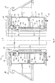
fig. 1 is a schematic representation in section of an apparatus for continuous casting according to the present invention; -
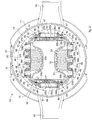
fig. 2 is a section view from II to II infig. 1 ; -
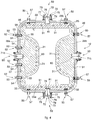
fig. 3 is a section view from III to III infig. 2 ; -
fig. 4 is a section view from IV to IV infig. 1 ; -
fig. 5 is a view of an enlarged detail offig. 4 ; -
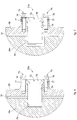
fig. 6 is an enlarged view of a first enlarged detail offig. 1 ; -
fig. 7 is an enlarged view of a second enlarged detail offig. 1 . - To facilitate comprehension, the same reference numbers have been used, where possible, to identify identical common elements in the drawings. It is understood that elements and characteristics of one form of embodiment can conveniently be incorporated into other forms of embodiment without further clarifications.
- With reference to
fig. 1 an apparatus for continuous casting is indicated in its entirety by thereference number 10 and comprises a support structure ormold body 11, to which amold 12 is associated, in this case, of the plate type. Themold body 11 also allows to install molds of the tubular type. - The
mold body 11 is provided with a containingcasing 13 in which, during use, themold 12 is inserted. Between the containingcasing 13 and the mold 12 aclosed chamber 15 is defined, to contain the cooling water. The containingcasing 13 is closed at the top by anupper flange 24 and below by alower flange 25. - A
separator element 14, located in the containingcompartment 15, is associated to the containingcasing 13 and to themold 12 and divides the containingcompartment 15 into anintroduction chamber 16 and adischarge chamber 17 of the cooling water. - The
separator element 14 is located inside the containingcompartment 15 transverse to the longitudinal extension of themold 12. - The
introduction chamber 16 and thedischarge chamber 17 are connected, by means of adelivery pipe 18 and, respectively adischarge pipe 19, to a plant to feed and treat the cooling water, not shown in the drawings. - Some forms of embodiment, for example those shown in
figs. 1 and2 , provide that theseparator element 14 comprises afirst portion 20 solidly coupled to themold body 11 and asecond portion 22 solidly attached to themold 12. - The
first portion 20 is attached to themold body 11, by means of welding for example, and is provided with a throughseating 21 configured to receive thesecond portion 22 of theseparator element 14. - Between the
first portion 20 and thesecond portion 22 of theseparator element 14 sealingmembers 23 are provided, such as packings, of the annular type or O-rings for example, which prevent the passage of cooling water between thedischarge chamber 17 and theintroduction chamber 16. - Other forms of embodiment can provide that the
separator element 14 is made in a single body and is solidly associated to themold body 11 or to themold 12 and extends taking itself into contact with themold 12 and themold body 11. - The
mold 12 develops longitudinally along a longitudinal axis Z which can have a rectilinear development, if theapparatus 10 is installed in a continuous casting machine of the vertical type, or it can have a slightly curved development if theapparatus 10 is installed in a curved continuous casting machine. - The
mold 12 comprises a first tubular element orconveyor 26, and a second tubular element orcrystallizer 27, disposed inside theconveyor 26. - The
conveyor 26 has the function of supporting thecrystallizer 27 as well as the function of separating the latter from theintroduction chamber 16 and from thedischarge chamber 17. - Between the
conveyor 26 and the crystallizer 27 ahollow space 51 is defined which is open toward the bottom to drain possible leaks of cooling water. In this way thecrystallizer 27 is not subjected to the pressure of the cooling water contained in theintroduction chamber 16 and thedischarge chamber 17, and is therefore not subjected to deformations. - The
crystallizer 27 comprises a plurality ofplates cavity 30 for the passage of the melted metal. - Each
plate passage channels 31 for the cooling water that extend through for the entire length of theplate - The
passage channels 31 can be made completely in the thickness of eachplate passage channels 31 are defined by longitudinal grooves open toward the outside and subsequently closed by closing elements. - Each
passage channel 31 has anentrance end 32a and anexit end 32b located in fluidic communication respectively with theintroduction chamber 16 and with thedischarge chamber 17 by means ofconnection channels plate - The entrance ends 32a are closed in their end part by a closing
flange 34, anchored to thelower flange 25. - The exit ends 32b, on the other hand, are closed by the
upper flange 24 of themold body 11. - Each
plate plates - One form of embodiment of the present invention, shown for example in
fig. 3 provides that a plurality of saidconnection channels 33b converge toward the external surface of theplates common discharge collectors 36b. Similar forms of embodiment can provide that theconnection channels 33a also converge toward the external surface of theplates common introduction collectors 36a (fig. 1 ). - The entrance ends 32a and the exit ends 32b of the
passage channels 31 are connected to theintroduction chamber 16 and to thedischarge chamber 17 by means of one or more connecting members. The entrance ends 32a and the exit ends 32b are connected toentrance sleeves 37a and respectively exitsleeves 37b. - Some forms of embodiment, shown for example in
fig. 3 , provide that eachentrance sleeve 37a and eachexit sleeve 37b allow to feed or discharge the cooling water into or fromseveral passage channels 31. To this end the connection of theentrance sleeves 37a and theexit sleeves 37b is provided in correspondence to theintroduction collectors 36a and respectively thedischarge collectors 36b. - The
entrance sleeves 37a and theexit sleeves 37b are attached to theconveyor 26 by connection means 38 so as to put their useful passage section in continuity with theintroduction collectors 36a and thedischarge collectors 36b. - Flow choking
members 45 are associated to at least one of either theentrance sleeves 37a or theexit sleeves 37b, in this case to theexit sleeves 37b. - The
flow choking members 45 allow to adjust the flow of cooling water in thepassage channels 31. A different calibration of theflow choking members 45 of each of theexit sleeves 37b allows to obtain differentiated cooling zones in thecrystallizer 27. - The
flow choking members 45 can comprise plates with calibrated holes, commandable or servo-commandable valves, or elements to obstruct/choke the flow or similar or comparable members suitable for the purpose. - This solution is particularly efficient if products are cast that have zones of the cross section with a variable thickness, such as Beam Blanks for example, in which the central area, or "core", has a different thickness from the external zones or "wings".
- In the form of embodiment in
fig. 3 , theflow adjustment members 45 comprise a plate 46 attached to theexit sleeve 37b by connection means 48, of the threaded type for example. - The plate 46 is provided with at least a calibrated
hole 47, smaller in size than the useful passage section of theexit sleeve 37b and which allows to adjust the flow rate of the cooling water. -
Connection members 50 are provided to connect theconveyor 26 and thecrystallizer 27 to each other. - In particular, the
connection members 50 are suitable to determine the reciprocal positioning of theplates conveyor 26. - In forms of embodiment shown in
figs. 1-4 , theconnection members 50 comprisefirst attachment devices 52 provided to constrain the reciprocal positioning of afirst plate 28a with the wall of theconveyor 26. - Some forms of embodiment of the present invention provide that the
first plate 28a is the one disposed toward the extrados of the curve of themold 12. - With reference to
fig. 4 , it is provided that thefirst attachment devices 52 comprise a plurality ofscrews 53 insertable in throughholes 54 made in the thickness of theconveyor 26. Thescrews 53 screw into threadedholes 55 made on the external surface of thefirst plate 28a and transverse to the longitudinal axis Z. - In the form of embodiment in
fig. 4 , between thefirst plate 28a and the wall of theconveyor 26 there is aspacer 56 with a distancing function. - Some forms of embodiment of the present invention provide that the wall of the
conveyor 26 to which thefirst plate 28a is attached is provided with protruding abutment portions which define references for the correct positioning of thefirst plate 28a with respect to theconveyor 26, and consequently also for theother plates - Second attachment devices 57 (
fig. 3 ) are provided to determine the reciprocal coupling of asecond plate 28b, opposite thefirst plate 28a, of athird plate 29a that connects in two first connection edges 35 of the first 28a and the second 28b plate, and of afourth plate 29b, opposite thethird plate 29a, which connects in two second connection edges 35 of thethird plate 29a and thefourth plate 29b. - In particular, the
second attachment devices 57 are configured to compress, in correspondence with their respective connection edges, thesecond plate 28b, thethird plate 29a and thefourth plate 29b against thefirst plate 28a. - Some forms of embodiment, one of which is shown in
fig. 5 , provide that thesecond attachment devices 57 comprise a plurality ofelastic blocks 58 attached to the external surface of thesecond plate 28b, of thethird plate 29a and of thefourth plate 29b, in this case to the external surface of thefourth plate 29b, and on whichthruster elements 64 act during use. Thethruster elements 64 are attached on the external surface of theconveyor 26 and are configured to compress the elastic blocks 58. - The
elastic blocks 58 comprise a containingbody 59 with a substantially cylindrical shape, provided to contain a plurality ofelastic elements 60 inside it. - In the form of embodiment shown in
fig. 5 , theelastic elements 60 comprise cup type springs, although in other forms of embodiment theelastic elements 60 can comprise compression springs of the helical type, conical disc springs or leaf springs or suchlike. - The containing
body 59 comprises acontainer 61 provided with anaperture 65 for the introduction of theelastic elements 60. - The
aperture 65 of thecontainer 61 is partly closed by alid 62 that provides to maintain theelastic elements 60 compressed inside thecontainer 61, and generates a first preloading thereof. - The
container 61 is housed, by mechanical interference, in a respectiveblind hole 63 made on the external surface of thesecond plate 28b, thethird plate 29a and thefourth plate 29b. - The reciprocal connection between the
container 61 and thelid 62 can be the threaded type or, in other forms of embodiment, by same-shape coupling or interference, for example providing snap-in attachment teeth of the non-releasable type. - The
lid 62 is provided with ahole 67 which allows thethruster elements 64 to cooperate with theelastic elements 60. Inside thecontainer 61, interposed between theelastic elements 60 and thelid 62, there is asmall plate 66 that protrudes toward the outside through thehole 67. -
Suitable abutments 68 are provided in thesmall plate 66 and in thelid 62, to prevent thesmall plate 66 from exiting from thecontainer 61. - The
thruster elements 64 comprise athrust screw 69 which is screwed into a threadedhole 70 made through through the thickness of theconveyor 26. - In particular, the threaded
hole 70 is made in a position coordinated to the one in which theblind hole 63 is provided for housing theelastic block 58. - The thrust screw 69 of each
second attachment device 57 presses against thesmall plate 66, compressing theelastic elements 60 inside the containingbody 59. - The action of compression of the
elastic elements 60 associated respectively to thesecond plate 28b, thethird plate 29a and thefourth plate 29b is transmitted onto these. - The overall effect of compression of the
elastic elements 60 therefore translates into an effect of compression of thesecond plate 28b, thethird plate 29a and thefourth plate 29b against thefirst plate 28a, which is the only one directly attached to theconveyor 26. - Assembling the
crystallizer 12 with theconveyor 26 comprises a first operation of introducing only thefirst plate 28a inside theconveyor 26, disposing it in contact against a wall of the latter. If necessary, it may be provided to interpose thespacer 56 between thefirst plate 28a and theconveyor 26 as described above. - The
first plate 28a is attached in theconveyor 26 by thefirst attachment devices 52 which exert a holding action of thefirst plate 28a against the wall of theconveyor 26. - A subsequent operation is provided to introduce the
second plate 28b, thethird plate 29a and thefourth plate 29b inside theconveyor 26, disposing them in reciprocal contact with their connection edges 35 of thefirst plate 28a. - Some forms of embodiment provide that the operation of introducing the
second plate 28b, thethird plate 29a, and thefourth plate 29b into theconveyor 26 occurs simultaneously. - In this case dedicated equipment can be provided that, before the insertion, reciprocally connects the
second plate 28b, thethird plate 29a and thefourth plate 29b, disposing them in the position they will assume during use. - The equipment, together with the
second plate 28b, thethird plate 29a and thefourth plate 29b is used to allow the simultaneous insertion of the latter inside theconveyor 26. - Other forms of embodiment can provide that the insertion of the
second plate 28b, thethird plate 29a and thefourth plate 29b occurs in sequence. - Once the
second plate 28b, thethird plate 29a and thefourth plate 29b are inserted in theconveyor 26, thesecond attachment devices 57 are activated. The activation of thesecond attachment devices 57 allows to compress thesecond plate 28b, thethird plate 29a and thefourth plate 29b against thefirst plate 28a. - In fact, while the
first plate 28a is held by thefirst attachment devices 52 against theconveyor 26, thesecond plate 28b, thethird plate 29a and thefourth plate 29b are thrust toward the inside of theconveyor 26 and the reciprocal cooperation between the connection edges 35 determines an assembled condition. - The fact that no direct connection is provided between the
plates plates - Other forms of embodiment of the present invention, shown for example in
figs. 1-7 , provide that theconnection members 50 comprisefirst positioning devices first plate 28a and thesecond plate 28b, and second positioning devices 72 (figs. 2 and4 ) provided to determine a precise positioning of thethird plate 29a and thefourth plate 29b with respect to theconveyor 26 in an axial direction, that is, along the longitudinal axis Z, and a transverse direction. - The
first positioning devices second positioning devices 72 comprise a plurality of pins 73 (figs. 2 and4-6 ) suitable to be inserted in respective throughholes 74 made in the thickness of theconveyor 26 and according to an axis that is located transverse to the longitudinal axis Z. - The position of the
pins 73 in the throughholes 74 is maintained byconnection members 75 which, in this case, comprise screws 76 inserted into throughholes 77 made in ahead 78 of thepin 73. - Each
first positioning device first housing seating 79, respectively 80, made blind in the thickness of the first 28a and the second 28b plate (figs. 6 and 7 ). - The
first housing seatings 79 of thefirst positioning devices 71a (fig. 6 ) are configured to constrain the position of the first 28a and the second 28b plate with respect to theconveyor 26 both in a direction parallel to the longitudinal axis Z and also in a transverse direction, for example orthogonal, to the longitudinal axis Z. - The
first housing seatings 80 of thefirst positioning devices 71b (fig. 7 ) on the other hand are configured to constrain the position of theplates - Each
second positioning device 72 comprises asecond housing seating 81 made blind in the thickness of the third 29a and the fourth 29b plate (figs. 2 and4 ). - Finally, the
second housing seatings 81 of the second positioning devices 72 (figs. 2 and4 ) are configured to constrain the position of the third 29a and the fourth 29b plate in a direction parallel to the longitudinal axis Z and to leave the movement free in a transverse direction, in this specific case, orthogonal, to the longitudinal axis Z, to allow any necessary adaption if theplates spacer 56 is modified. - In fact, because of wear on the
plates plates - The
first plate 28a changes its total thickness and, in order to maintain the positioning of the internal profile unchanged with respect to the machine, aspacer 56 is inserted, with a calibrated thickness with respect to thesupport frame 26. These operations produce very slight movements of the theoretical center of theplates - In general, the positioning of the
crystallizer 27 in thesupport frame 26 is given by the abutment to which thefirst plate 28a is attached. A rigid positioning constraint makes it impossible to assemble thecrystallizer 27 in thesupport frame 26. - In this respect, both the
first housing seatings 80 and thesecond housing seatings 81 have a greater size compared to the size of the diameter of thepin 73 in the direction in which a movement of theplates - The freedom of movement of the
plates pins 73 allows to take into account possible thermal dilations to which the latter are subjected during use, and thus prevent the onset of internal stresses that could deform thecrystallizer 27, generating cast products with unwanted geometric and microstructural characteristics, as well as reducing the useful life of thecrystallizer 27 itself. - It is clear that modifications and/or additions of parts may be made to the continuous casting apparatus as described heretofore, without departing from the field and scope of the present invention.
- It is also clear that, although the present invention has been described with reference to some specific examples, a person of skill in the art shall certainly be able to achieve many other equivalent forms of continuous casting apparatus, having the characteristics as set forth in the claims and hence all coming within the field of protection defined thereby.
Claims (9)
- Apparatus for continuous casting comprising a support structure (11) provided with a containing casing (13) configured to support inside it a mold (12) equipped with a plurality of longitudinal passage channels (31) for the passage of a cooling liquid, said containing casing (13) and said mold (12) together defining an introduction chamber (16) and a discharge chamber (17) for said cooling liquid, and said introduction chamber (16) and said discharge chamber (17) being fluidically connected by said passage channels (31), said mold (12) comprises a first tubular element (26) and a second tubular element (27) disposed inside said first tubular element (26), characterized in that said second tubular element (27) comprises a plurality of plates (28a, 28b, 29a, 29b) each provided with said passage channels (31) and connected to each other to define a through casting cavity (30), and in that said first tubular element (26) is provided with connection members (37a, 37b) to connect said passage channels (31) of the plates (28a, 28b, 29a, 29b) respectively with said introduction chamber (16) and with said discharge chamber (17).
- Apparatus as in claim 1, characterized in that a hollow space (51) is defined between said first tubular element (26) and said second tubular element (27).
- Apparatus as in claim 1 or 2, characterized in that each of said plates (28a, 28b, 29a, 29b) is served by its own connection members (37a, 37b).
- Apparatus as in claim 3, characterized in that each of said connection members (37a, 37b) is connected to a plurality of said passage channels (31).
- Apparatus as in any claim hereinbefore, characterized in that flow adjustment members (45), provided to adjust the flow rate of cooling liquid in said passage channels (31), are associated to at least one of said connection members (37a, 37b).
- Apparatus as in claim 5, characterized in that said flow adjustment members (45) comprise plates with calibrated holes, commandable or servo-commandable valves, or elements to obstruct/choke the flow.
- Apparatus as in any claim hereinbefore, characterized in that said introduction chamber (16) and said discharge chamber (17) are divided by a separator element (14) associated to said containing casing (13) and to said mold (12).
- Apparatus as in claim 7, characterized in that said separator element (14) is disposed transverse to the longitudinal extension of said mold (12).
- Apparatus as in claim 7 or 8, characterized in that said separator element (14) comprises a first portion (20) connected to said containing casing (13) and a second portion (22) connected to the walls of said first tubular element (26).
Applications Claiming Priority (2)
| Application Number | Priority Date | Filing Date | Title |
|---|---|---|---|
| IT000053A ITUD20130053A1 (en) | 2013-04-23 | 2013-04-23 | APPARATUS FOR CONTINUOUS CASTING |
| PCT/IB2014/060922 WO2014174445A1 (en) | 2013-04-23 | 2014-04-23 | Apparatus for continuous casting |
Publications (2)
| Publication Number | Publication Date |
|---|---|
| EP2988890A1 EP2988890A1 (en) | 2016-03-02 |
| EP2988890B1 true EP2988890B1 (en) | 2019-02-27 |
Family
ID=48579413
Family Applications (1)
| Application Number | Title | Priority Date | Filing Date |
|---|---|---|---|
| EP14731013.0A Active EP2988890B1 (en) | 2013-04-23 | 2014-04-23 | Apparatus for continuous casting |
Country Status (5)
| Country | Link |
|---|---|
| US (1) | US20160082503A1 (en) |
| EP (1) | EP2988890B1 (en) |
| CN (1) | CN105555438A (en) |
| IT (1) | ITUD20130053A1 (en) |
| WO (1) | WO2014174445A1 (en) |
Families Citing this family (5)
| Publication number | Priority date | Publication date | Assignee | Title |
|---|---|---|---|---|
| CZ2016267A3 (en) * | 2016-05-10 | 2017-06-28 | MATERIÁLOVÝ A METALURGICKÝ VÝZKUM s.r.o. | An ingot mould assembly with water cooling |
| US10661324B2 (en) * | 2017-04-25 | 2020-05-26 | Stolle Machinery Company, Llc | Tool pack clamp cover |
| CN109702155A (en) * | 2019-03-14 | 2019-05-03 | 山东钢铁股份有限公司 | A kind of conticaster and its special-shaped bad continuous cast mold of near-net-shape |
| CN112170794B (en) * | 2020-09-30 | 2022-03-08 | 江苏华龙铸铁型材有限公司 | Combined type abdomen cooling crystallizer for producing track section bar |
| CN120551336B (en) * | 2025-07-31 | 2025-09-30 | 伟兴有限公司 | Environment-friendly casting molding equipment for producing high-low voltage switch cabinet parts |
Family Cites Families (13)
| Publication number | Priority date | Publication date | Assignee | Title |
|---|---|---|---|---|
| GB1034473A (en) * | 1963-02-14 | 1966-06-29 | Davy & United Eng Co Ltd | Continuous casting |
| GB1151361A (en) * | 1965-08-19 | 1969-05-07 | United Steel Companies Ltd | Continuous Casting Machines |
| DE3411359A1 (en) * | 1984-03-28 | 1985-10-31 | Mannesmann AG, 4000 Düsseldorf | CONTINUOUS CHOCOLATE FOR ROUND OR BLOCK CROSS SECTIONS, ESPECIALLY FOR THE POURING OF LIQUID STEEL |
| ES2148375T3 (en) * | 1994-06-06 | 2000-10-16 | Danieli Off Mecc | CONTINUOUS CAST GLASS WITH MORE HEAT EXCHANGE AND METHOD TO INCREASE HEAT EXCHANGE IN A CONTINUOUS CAST GLASS. |
| JPH0810906A (en) * | 1994-06-29 | 1996-01-16 | Nippon Steel Corp | Cooling structure of continuous casting mold |
| CN2236914Y (en) * | 1995-01-18 | 1996-10-09 | 中国第一冶金建设公司机械厂 | Super long copper inner sleeve type crystallizer for horizontal continuous casting machine |
| LU88689A1 (en) * | 1995-12-22 | 1997-06-22 | Wurth Paul Sa | Continuous casting mold |
| DE19810672B4 (en) * | 1998-03-12 | 2006-02-09 | Sms Demag Ag | Method and continuous casting mold for producing slab strands, in particular of steel |
| EP1712313A1 (en) * | 2005-04-13 | 2006-10-18 | Profilarbed S.A. | Continuous metal casting mould |
| CN102303103A (en) * | 2011-09-27 | 2012-01-04 | 中冶南方工程技术有限公司 | Efficient heat transfer type special-shaped blank continuous casting crystallizer |
| CN102335728B (en) * | 2011-10-26 | 2013-07-17 | 中冶南方工程技术有限公司 | Continuous casting crystallizer for H-shaped special-shaped blank |
| CN202291315U (en) * | 2011-10-26 | 2012-07-04 | 宝山钢铁股份有限公司 | Fixed water slot type continuous casting mold |
| CN202263907U (en) * | 2011-10-27 | 2012-06-06 | 上海宝钢设备检修有限公司 | Cooling structure for assembled type continuous casting crystallizer |
-
2013
- 2013-04-23 IT IT000053A patent/ITUD20130053A1/en unknown
-
2014
- 2014-04-23 WO PCT/IB2014/060922 patent/WO2014174445A1/en not_active Ceased
- 2014-04-23 EP EP14731013.0A patent/EP2988890B1/en active Active
- 2014-04-23 US US14/786,525 patent/US20160082503A1/en not_active Abandoned
- 2014-04-23 CN CN201480035964.8A patent/CN105555438A/en active Pending
Non-Patent Citations (1)
| Title |
|---|
| None * |
Also Published As
| Publication number | Publication date |
|---|---|
| ITUD20130053A1 (en) | 2014-10-24 |
| US20160082503A1 (en) | 2016-03-24 |
| EP2988890A1 (en) | 2016-03-02 |
| CN105555438A (en) | 2016-05-04 |
| WO2014174445A1 (en) | 2014-10-30 |
Similar Documents
| Publication | Publication Date | Title |
|---|---|---|
| US20160082503A1 (en) | Apparatus for Continuous Casting | |
| EP3395473B1 (en) | Method for casting | |
| CN106335209B (en) | Fine blanking press | |
| EP2473298B2 (en) | Roller and roller assembly for a continuous casting device | |
| EP2585270B1 (en) | Injection system | |
| EP3487650B1 (en) | Permanent mold plate and permanent mold | |
| KR20200024512A (en) | Die casting mold apparatus | |
| KR20110017891A (en) | Continuous casting mold for continuous casting plant | |
| EP3523069B1 (en) | Mold divider for installing in a mold | |
| DE1296007B (en) | Piston pump, in particular multi-cylinder high pressure piston pump | |
| US4506724A (en) | Ingot mold with adjustable dimensions for a continuous casting machine | |
| CN105328174A (en) | Rapid water gap replacement device for beam blank continuous casting tundish | |
| DE102015208964A1 (en) | Method for casting metal, adapter unit and apparatus for casting metal comprising such an adapter unit | |
| EP2988889B1 (en) | Apparatus for continuous casting and method to assemble said apparatus for continuous casting | |
| EP0079330B1 (en) | Mould for the multiple continuous casting of metal wires and bars having a small cross-section | |
| CN106578272B (en) | A kind of chocolate casting device | |
| AT522298B1 (en) | Mold unit for the continuous casting of metal products as well as a continuous caster | |
| EP2919930B1 (en) | Method to manufacture a crystallizer with plates for the continuous casting of slabs, and crystallizer thus obtained | |
| KR102090213B1 (en) | Apparatus for driving and apparatus for casting having the same | |
| RU2433883C2 (en) | Crystalliser suspension | |
| EP1486273A1 (en) | Continuous casting mould with adjusting device for the copper plates enclosing the casting cavity | |
| EP2439474A2 (en) | Device for drying a machine part with a vacuum drying chamber | |
| EP3525955B1 (en) | Mold having a mold divider | |
| DE3134398C2 (en) | Method and device for the production of die castings | |
| EA038778B1 (en) | Thermoregulated rubber distributor for injection molds |
Legal Events
| Date | Code | Title | Description |
|---|---|---|---|
| PUAI | Public reference made under article 153(3) epc to a published international application that has entered the european phase |
Free format text: ORIGINAL CODE: 0009012 |
|
| 17P | Request for examination filed |
Effective date: 20151123 |
|
| AK | Designated contracting states |
Kind code of ref document: A1 Designated state(s): AL AT BE BG CH CY CZ DE DK EE ES FI FR GB GR HR HU IE IS IT LI LT LU LV MC MK MT NL NO PL PT RO RS SE SI SK SM TR |
|
| AX | Request for extension of the european patent |
Extension state: BA ME |
|
| DAX | Request for extension of the european patent (deleted) | ||
| STAA | Information on the status of an ep patent application or granted ep patent |
Free format text: STATUS: EXAMINATION IS IN PROGRESS |
|
| 17Q | First examination report despatched |
Effective date: 20161205 |
|
| GRAP | Despatch of communication of intention to grant a patent |
Free format text: ORIGINAL CODE: EPIDOSNIGR1 |
|
| STAA | Information on the status of an ep patent application or granted ep patent |
Free format text: STATUS: GRANT OF PATENT IS INTENDED |
|
| INTG | Intention to grant announced |
Effective date: 20180831 |
|
| GRAS | Grant fee paid |
Free format text: ORIGINAL CODE: EPIDOSNIGR3 |
|
| GRAA | (expected) grant |
Free format text: ORIGINAL CODE: 0009210 |
|
| STAA | Information on the status of an ep patent application or granted ep patent |
Free format text: STATUS: THE PATENT HAS BEEN GRANTED |
|
| AK | Designated contracting states |
Kind code of ref document: B1 Designated state(s): AL AT BE BG CH CY CZ DE DK EE ES FI FR GB GR HR HU IE IS IT LI LT LU LV MC MK MT NL NO PL PT RO RS SE SI SK SM TR |
|
| REG | Reference to a national code |
Ref country code: GB Ref legal event code: FG4D |
|
| REG | Reference to a national code |
Ref country code: CH Ref legal event code: EP |
|
| REG | Reference to a national code |
Ref country code: AT Ref legal event code: REF Ref document number: 1100589 Country of ref document: AT Kind code of ref document: T Effective date: 20190315 |
|
| REG | Reference to a national code |
Ref country code: IE Ref legal event code: FG4D |
|
| REG | Reference to a national code |
Ref country code: DE Ref legal event code: R096 Ref document number: 602014041798 Country of ref document: DE |
|
| REG | Reference to a national code |
Ref country code: NL Ref legal event code: MP Effective date: 20190227 |
|
| REG | Reference to a national code |
Ref country code: LT Ref legal event code: MG4D |
|
| PG25 | Lapsed in a contracting state [announced via postgrant information from national office to epo] |
Ref country code: FI Free format text: LAPSE BECAUSE OF FAILURE TO SUBMIT A TRANSLATION OF THE DESCRIPTION OR TO PAY THE FEE WITHIN THE PRESCRIBED TIME-LIMIT Effective date: 20190227 Ref country code: LT Free format text: LAPSE BECAUSE OF FAILURE TO SUBMIT A TRANSLATION OF THE DESCRIPTION OR TO PAY THE FEE WITHIN THE PRESCRIBED TIME-LIMIT Effective date: 20190227 Ref country code: NL Free format text: LAPSE BECAUSE OF FAILURE TO SUBMIT A TRANSLATION OF THE DESCRIPTION OR TO PAY THE FEE WITHIN THE PRESCRIBED TIME-LIMIT Effective date: 20190227 Ref country code: PT Free format text: LAPSE BECAUSE OF FAILURE TO SUBMIT A TRANSLATION OF THE DESCRIPTION OR TO PAY THE FEE WITHIN THE PRESCRIBED TIME-LIMIT Effective date: 20190627 Ref country code: SE Free format text: LAPSE BECAUSE OF FAILURE TO SUBMIT A TRANSLATION OF THE DESCRIPTION OR TO PAY THE FEE WITHIN THE PRESCRIBED TIME-LIMIT Effective date: 20190227 Ref country code: NO Free format text: LAPSE BECAUSE OF FAILURE TO SUBMIT A TRANSLATION OF THE DESCRIPTION OR TO PAY THE FEE WITHIN THE PRESCRIBED TIME-LIMIT Effective date: 20190527 |
|
| PG25 | Lapsed in a contracting state [announced via postgrant information from national office to epo] |
Ref country code: HR Free format text: LAPSE BECAUSE OF FAILURE TO SUBMIT A TRANSLATION OF THE DESCRIPTION OR TO PAY THE FEE WITHIN THE PRESCRIBED TIME-LIMIT Effective date: 20190227 Ref country code: RS Free format text: LAPSE BECAUSE OF FAILURE TO SUBMIT A TRANSLATION OF THE DESCRIPTION OR TO PAY THE FEE WITHIN THE PRESCRIBED TIME-LIMIT Effective date: 20190227 Ref country code: LV Free format text: LAPSE BECAUSE OF FAILURE TO SUBMIT A TRANSLATION OF THE DESCRIPTION OR TO PAY THE FEE WITHIN THE PRESCRIBED TIME-LIMIT Effective date: 20190227 Ref country code: IS Free format text: LAPSE BECAUSE OF FAILURE TO SUBMIT A TRANSLATION OF THE DESCRIPTION OR TO PAY THE FEE WITHIN THE PRESCRIBED TIME-LIMIT Effective date: 20190627 Ref country code: BG Free format text: LAPSE BECAUSE OF FAILURE TO SUBMIT A TRANSLATION OF THE DESCRIPTION OR TO PAY THE FEE WITHIN THE PRESCRIBED TIME-LIMIT Effective date: 20190527 Ref country code: GR Free format text: LAPSE BECAUSE OF FAILURE TO SUBMIT A TRANSLATION OF THE DESCRIPTION OR TO PAY THE FEE WITHIN THE PRESCRIBED TIME-LIMIT Effective date: 20190528 |
|
| PG25 | Lapsed in a contracting state [announced via postgrant information from national office to epo] |
Ref country code: ES Free format text: LAPSE BECAUSE OF FAILURE TO SUBMIT A TRANSLATION OF THE DESCRIPTION OR TO PAY THE FEE WITHIN THE PRESCRIBED TIME-LIMIT Effective date: 20190227 Ref country code: RO Free format text: LAPSE BECAUSE OF FAILURE TO SUBMIT A TRANSLATION OF THE DESCRIPTION OR TO PAY THE FEE WITHIN THE PRESCRIBED TIME-LIMIT Effective date: 20190227 Ref country code: CZ Free format text: LAPSE BECAUSE OF FAILURE TO SUBMIT A TRANSLATION OF THE DESCRIPTION OR TO PAY THE FEE WITHIN THE PRESCRIBED TIME-LIMIT Effective date: 20190227 Ref country code: SK Free format text: LAPSE BECAUSE OF FAILURE TO SUBMIT A TRANSLATION OF THE DESCRIPTION OR TO PAY THE FEE WITHIN THE PRESCRIBED TIME-LIMIT Effective date: 20190227 Ref country code: AL Free format text: LAPSE BECAUSE OF FAILURE TO SUBMIT A TRANSLATION OF THE DESCRIPTION OR TO PAY THE FEE WITHIN THE PRESCRIBED TIME-LIMIT Effective date: 20190227 Ref country code: EE Free format text: LAPSE BECAUSE OF FAILURE TO SUBMIT A TRANSLATION OF THE DESCRIPTION OR TO PAY THE FEE WITHIN THE PRESCRIBED TIME-LIMIT Effective date: 20190227 Ref country code: DK Free format text: LAPSE BECAUSE OF FAILURE TO SUBMIT A TRANSLATION OF THE DESCRIPTION OR TO PAY THE FEE WITHIN THE PRESCRIBED TIME-LIMIT Effective date: 20190227 |
|
| REG | Reference to a national code |
Ref country code: DE Ref legal event code: R097 Ref document number: 602014041798 Country of ref document: DE |
|
| PG25 | Lapsed in a contracting state [announced via postgrant information from national office to epo] |
Ref country code: SM Free format text: LAPSE BECAUSE OF FAILURE TO SUBMIT A TRANSLATION OF THE DESCRIPTION OR TO PAY THE FEE WITHIN THE PRESCRIBED TIME-LIMIT Effective date: 20190227 Ref country code: PL Free format text: LAPSE BECAUSE OF FAILURE TO SUBMIT A TRANSLATION OF THE DESCRIPTION OR TO PAY THE FEE WITHIN THE PRESCRIBED TIME-LIMIT Effective date: 20190227 |
|
| REG | Reference to a national code |
Ref country code: CH Ref legal event code: PL |
|
| REG | Reference to a national code |
Ref country code: BE Ref legal event code: MM Effective date: 20190430 |
|
| PG25 | Lapsed in a contracting state [announced via postgrant information from national office to epo] |
Ref country code: MC Free format text: LAPSE BECAUSE OF FAILURE TO SUBMIT A TRANSLATION OF THE DESCRIPTION OR TO PAY THE FEE WITHIN THE PRESCRIBED TIME-LIMIT Effective date: 20190227 Ref country code: LU Free format text: LAPSE BECAUSE OF NON-PAYMENT OF DUE FEES Effective date: 20190423 |
|
| PLBE | No opposition filed within time limit |
Free format text: ORIGINAL CODE: 0009261 |
|
| STAA | Information on the status of an ep patent application or granted ep patent |
Free format text: STATUS: NO OPPOSITION FILED WITHIN TIME LIMIT |
|
| GBPC | Gb: european patent ceased through non-payment of renewal fee |
Effective date: 20190527 |
|
| PG25 | Lapsed in a contracting state [announced via postgrant information from national office to epo] |
Ref country code: CH Free format text: LAPSE BECAUSE OF NON-PAYMENT OF DUE FEES Effective date: 20190430 Ref country code: LI Free format text: LAPSE BECAUSE OF NON-PAYMENT OF DUE FEES Effective date: 20190430 |
|
| 26N | No opposition filed |
Effective date: 20191128 |
|
| PG25 | Lapsed in a contracting state [announced via postgrant information from national office to epo] |
Ref country code: FR Free format text: LAPSE BECAUSE OF NON-PAYMENT OF DUE FEES Effective date: 20190427 Ref country code: SI Free format text: LAPSE BECAUSE OF FAILURE TO SUBMIT A TRANSLATION OF THE DESCRIPTION OR TO PAY THE FEE WITHIN THE PRESCRIBED TIME-LIMIT Effective date: 20190227 Ref country code: BE Free format text: LAPSE BECAUSE OF NON-PAYMENT OF DUE FEES Effective date: 20190430 |
|
| PG25 | Lapsed in a contracting state [announced via postgrant information from national office to epo] |
Ref country code: TR Free format text: LAPSE BECAUSE OF FAILURE TO SUBMIT A TRANSLATION OF THE DESCRIPTION OR TO PAY THE FEE WITHIN THE PRESCRIBED TIME-LIMIT Effective date: 20190227 |
|
| PG25 | Lapsed in a contracting state [announced via postgrant information from national office to epo] |
Ref country code: IE Free format text: LAPSE BECAUSE OF NON-PAYMENT OF DUE FEES Effective date: 20190423 Ref country code: GB Free format text: LAPSE BECAUSE OF NON-PAYMENT OF DUE FEES Effective date: 20190527 |
|
| REG | Reference to a national code |
Ref country code: AT Ref legal event code: UEP Ref document number: 1100589 Country of ref document: AT Kind code of ref document: T Effective date: 20190227 |
|
| PG25 | Lapsed in a contracting state [announced via postgrant information from national office to epo] |
Ref country code: CY Free format text: LAPSE BECAUSE OF FAILURE TO SUBMIT A TRANSLATION OF THE DESCRIPTION OR TO PAY THE FEE WITHIN THE PRESCRIBED TIME-LIMIT Effective date: 20190227 |
|
| PG25 | Lapsed in a contracting state [announced via postgrant information from national office to epo] |
Ref country code: HU Free format text: LAPSE BECAUSE OF FAILURE TO SUBMIT A TRANSLATION OF THE DESCRIPTION OR TO PAY THE FEE WITHIN THE PRESCRIBED TIME-LIMIT; INVALID AB INITIO Effective date: 20140423 Ref country code: MT Free format text: LAPSE BECAUSE OF FAILURE TO SUBMIT A TRANSLATION OF THE DESCRIPTION OR TO PAY THE FEE WITHIN THE PRESCRIBED TIME-LIMIT Effective date: 20190227 |
|
| PG25 | Lapsed in a contracting state [announced via postgrant information from national office to epo] |
Ref country code: MK Free format text: LAPSE BECAUSE OF FAILURE TO SUBMIT A TRANSLATION OF THE DESCRIPTION OR TO PAY THE FEE WITHIN THE PRESCRIBED TIME-LIMIT Effective date: 20190227 |
|
| P01 | Opt-out of the competence of the unified patent court (upc) registered |
Effective date: 20230516 |
|
| PGFP | Annual fee paid to national office [announced via postgrant information from national office to epo] |
Ref country code: DE Payment date: 20250429 Year of fee payment: 12 |
|
| PGFP | Annual fee paid to national office [announced via postgrant information from national office to epo] |
Ref country code: IT Payment date: 20250422 Year of fee payment: 12 |
|
| PGFP | Annual fee paid to national office [announced via postgrant information from national office to epo] |
Ref country code: AT Payment date: 20250402 Year of fee payment: 12 |