EP2988694B1 - Robot, particularly for mini-invasive surgery through a single parietal incision or natural orifice - Google Patents
Robot, particularly for mini-invasive surgery through a single parietal incision or natural orifice Download PDFInfo
- Publication number
- EP2988694B1 EP2988694B1 EP14718985.6A EP14718985A EP2988694B1 EP 2988694 B1 EP2988694 B1 EP 2988694B1 EP 14718985 A EP14718985 A EP 14718985A EP 2988694 B1 EP2988694 B1 EP 2988694B1
- Authority
- EP
- European Patent Office
- Prior art keywords
- articulated support
- robot
- maneuvering
- guide
- container body
- Prior art date
- Legal status (The legal status is an assumption and is not a legal conclusion. Google has not performed a legal analysis and makes no representation as to the accuracy of the status listed.)
- Active
Links
- 238000001356 surgical procedure Methods 0.000 title claims description 11
- 230000001936 parietal effect Effects 0.000 title claims description 7
- 238000003780 insertion Methods 0.000 claims description 52
- 230000037431 insertion Effects 0.000 claims description 52
- 238000013519 translation Methods 0.000 claims description 19
- 230000007704 transition Effects 0.000 claims description 4
- 230000013011 mating Effects 0.000 claims description 3
- 230000033001 locomotion Effects 0.000 description 9
- 230000008901 benefit Effects 0.000 description 5
- 230000000903 blocking effect Effects 0.000 description 4
- 230000008878 coupling Effects 0.000 description 4
- 238000010168 coupling process Methods 0.000 description 4
- 238000005859 coupling reaction Methods 0.000 description 4
- 238000000034 method Methods 0.000 description 4
- 238000002357 laparoscopic surgery Methods 0.000 description 3
- 239000000463 material Substances 0.000 description 3
- 230000003187 abdominal effect Effects 0.000 description 2
- 238000013459 approach Methods 0.000 description 2
- 230000005540 biological transmission Effects 0.000 description 2
- 238000000605 extraction Methods 0.000 description 2
- 210000000245 forearm Anatomy 0.000 description 2
- 230000000670 limiting effect Effects 0.000 description 2
- 230000002980 postoperative effect Effects 0.000 description 2
- 210000001519 tissue Anatomy 0.000 description 2
- 208000032843 Hemorrhage Diseases 0.000 description 1
- 206010021620 Incisional hernias Diseases 0.000 description 1
- 208000004550 Postoperative Pain Diseases 0.000 description 1
- 210000001015 abdomen Anatomy 0.000 description 1
- 238000012084 abdominal surgery Methods 0.000 description 1
- 210000003815 abdominal wall Anatomy 0.000 description 1
- 230000004913 activation Effects 0.000 description 1
- 210000003484 anatomy Anatomy 0.000 description 1
- 238000005452 bending Methods 0.000 description 1
- 230000015572 biosynthetic process Effects 0.000 description 1
- 208000034158 bleeding Diseases 0.000 description 1
- 230000000740 bleeding effect Effects 0.000 description 1
- 230000002860 competitive effect Effects 0.000 description 1
- 230000001419 dependent effect Effects 0.000 description 1
- 238000001727 in vivo Methods 0.000 description 1
- 208000015181 infectious disease Diseases 0.000 description 1
- 238000009434 installation Methods 0.000 description 1
- 230000002262 irrigation Effects 0.000 description 1
- 238000003973 irrigation Methods 0.000 description 1
- 239000007788 liquid Substances 0.000 description 1
- 230000014759 maintenance of location Effects 0.000 description 1
- 230000007246 mechanism Effects 0.000 description 1
- 239000002184 metal Substances 0.000 description 1
- 238000012986 modification Methods 0.000 description 1
- 230000004048 modification Effects 0.000 description 1
- 230000036961 partial effect Effects 0.000 description 1
- 230000001575 pathological effect Effects 0.000 description 1
- 210000003200 peritoneal cavity Anatomy 0.000 description 1
- 238000012546 transfer Methods 0.000 description 1
- 210000001835 viscera Anatomy 0.000 description 1
- 238000004804 winding Methods 0.000 description 1
- 210000000707 wrist Anatomy 0.000 description 1
Images


Classifications
-
- A—HUMAN NECESSITIES
- A61—MEDICAL OR VETERINARY SCIENCE; HYGIENE
- A61B—DIAGNOSIS; SURGERY; IDENTIFICATION
- A61B34/00—Computer-aided surgery; Manipulators or robots specially adapted for use in surgery
- A61B34/30—Surgical robots
-
- A—HUMAN NECESSITIES
- A61—MEDICAL OR VETERINARY SCIENCE; HYGIENE
- A61B—DIAGNOSIS; SURGERY; IDENTIFICATION
- A61B1/00—Instruments for performing medical examinations of the interior of cavities or tubes of the body by visual or photographical inspection, e.g. endoscopes; Illuminating arrangements therefor
- A61B1/00147—Holding or positioning arrangements
- A61B1/00148—Holding or positioning arrangements using anchoring means
-
- A—HUMAN NECESSITIES
- A61—MEDICAL OR VETERINARY SCIENCE; HYGIENE
- A61B—DIAGNOSIS; SURGERY; IDENTIFICATION
- A61B1/00—Instruments for performing medical examinations of the interior of cavities or tubes of the body by visual or photographical inspection, e.g. endoscopes; Illuminating arrangements therefor
- A61B1/00147—Holding or positioning arrangements
- A61B1/00149—Holding or positioning arrangements using articulated arms
-
- A—HUMAN NECESSITIES
- A61—MEDICAL OR VETERINARY SCIENCE; HYGIENE
- A61B—DIAGNOSIS; SURGERY; IDENTIFICATION
- A61B1/00—Instruments for performing medical examinations of the interior of cavities or tubes of the body by visual or photographical inspection, e.g. endoscopes; Illuminating arrangements therefor
- A61B1/00147—Holding or positioning arrangements
- A61B1/0016—Holding or positioning arrangements using motor drive units
-
- A—HUMAN NECESSITIES
- A61—MEDICAL OR VETERINARY SCIENCE; HYGIENE
- A61B—DIAGNOSIS; SURGERY; IDENTIFICATION
- A61B90/00—Instruments, implements or accessories specially adapted for surgery or diagnosis and not covered by any of the groups A61B1/00 - A61B50/00, e.g. for luxation treatment or for protecting wound edges
- A61B90/30—Devices for illuminating a surgical field, the devices having an interrelation with other surgical devices or with a surgical procedure
- A61B90/35—Supports therefor
-
- A—HUMAN NECESSITIES
- A61—MEDICAL OR VETERINARY SCIENCE; HYGIENE
- A61B—DIAGNOSIS; SURGERY; IDENTIFICATION
- A61B17/00—Surgical instruments, devices or methods, e.g. tourniquets
- A61B17/00234—Surgical instruments, devices or methods, e.g. tourniquets for minimally invasive surgery
- A61B2017/00362—Packages or dispensers for MIS instruments
-
- A—HUMAN NECESSITIES
- A61—MEDICAL OR VETERINARY SCIENCE; HYGIENE
- A61B—DIAGNOSIS; SURGERY; IDENTIFICATION
- A61B17/00—Surgical instruments, devices or methods, e.g. tourniquets
- A61B2017/00477—Coupling
-
- A—HUMAN NECESSITIES
- A61—MEDICAL OR VETERINARY SCIENCE; HYGIENE
- A61B—DIAGNOSIS; SURGERY; IDENTIFICATION
- A61B17/00—Surgical instruments, devices or methods, e.g. tourniquets
- A61B17/28—Surgical forceps
- A61B17/29—Forceps for use in minimally invasive surgery
- A61B2017/2926—Details of heads or jaws
- A61B2017/2931—Details of heads or jaws with releasable head
-
- A—HUMAN NECESSITIES
- A61—MEDICAL OR VETERINARY SCIENCE; HYGIENE
- A61B—DIAGNOSIS; SURGERY; IDENTIFICATION
- A61B17/00—Surgical instruments, devices or methods, e.g. tourniquets
- A61B17/28—Surgical forceps
- A61B17/29—Forceps for use in minimally invasive surgery
- A61B2017/2926—Details of heads or jaws
- A61B2017/2932—Transmission of forces to jaw members
- A61B2017/2939—Details of linkages or pivot points
- A61B2017/294—Connection of actuating rod to jaw, e.g. releasable
-
- A—HUMAN NECESSITIES
- A61—MEDICAL OR VETERINARY SCIENCE; HYGIENE
- A61B—DIAGNOSIS; SURGERY; IDENTIFICATION
- A61B34/00—Computer-aided surgery; Manipulators or robots specially adapted for use in surgery
- A61B34/30—Surgical robots
- A61B2034/302—Surgical robots specifically adapted for manipulations within body cavities, e.g. within abdominal or thoracic cavities
-
- A—HUMAN NECESSITIES
- A61—MEDICAL OR VETERINARY SCIENCE; HYGIENE
- A61B—DIAGNOSIS; SURGERY; IDENTIFICATION
- A61B34/00—Computer-aided surgery; Manipulators or robots specially adapted for use in surgery
- A61B34/30—Surgical robots
- A61B2034/305—Details of wrist mechanisms at distal ends of robotic arms
- A61B2034/306—Wrists with multiple vertebrae
-
- A—HUMAN NECESSITIES
- A61—MEDICAL OR VETERINARY SCIENCE; HYGIENE
- A61B—DIAGNOSIS; SURGERY; IDENTIFICATION
- A61B90/00—Instruments, implements or accessories specially adapted for surgery or diagnosis and not covered by any of the groups A61B1/00 - A61B50/00, e.g. for luxation treatment or for protecting wound edges
- A61B90/10—Instruments, implements or accessories specially adapted for surgery or diagnosis and not covered by any of the groups A61B1/00 - A61B50/00, e.g. for luxation treatment or for protecting wound edges for stereotaxic surgery, e.g. frame-based stereotaxis
- A61B90/11—Instruments, implements or accessories specially adapted for surgery or diagnosis and not covered by any of the groups A61B1/00 - A61B50/00, e.g. for luxation treatment or for protecting wound edges for stereotaxic surgery, e.g. frame-based stereotaxis with guides for needles or instruments, e.g. arcuate slides or ball joints
-
- A—HUMAN NECESSITIES
- A61—MEDICAL OR VETERINARY SCIENCE; HYGIENE
- A61B—DIAGNOSIS; SURGERY; IDENTIFICATION
- A61B90/00—Instruments, implements or accessories specially adapted for surgery or diagnosis and not covered by any of the groups A61B1/00 - A61B50/00, e.g. for luxation treatment or for protecting wound edges
- A61B90/30—Devices for illuminating a surgical field, the devices having an interrelation with other surgical devices or with a surgical procedure
-
- A—HUMAN NECESSITIES
- A61—MEDICAL OR VETERINARY SCIENCE; HYGIENE
- A61B—DIAGNOSIS; SURGERY; IDENTIFICATION
- A61B90/00—Instruments, implements or accessories specially adapted for surgery or diagnosis and not covered by any of the groups A61B1/00 - A61B50/00, e.g. for luxation treatment or for protecting wound edges
- A61B90/36—Image-producing devices or illumination devices not otherwise provided for
- A61B90/361—Image-producing devices, e.g. surgical cameras
Definitions
- the present invention relates to a robot, particularly for mini-invasive surgery through a single parietal incision or natural orifice.
- mini-invasive techniques has become the standard for many routine surgical procedures.
- laparoscopy procedures have great drawbacks, which include difficulties in accessing the surgical target and the technical limitations of working with coaxial surgical instruments. These limitations are particularly clear when one operates through a single parietal access opening (single incision) and/or natural orifice in the patient.
- This surgical technique imposes constrains on the possibility of triangulating the instruments, applying offset forces, and on the dimensions of the instruments themselves. Moreover, collisions often occur among instruments both inside and outside the operating surgical area.
- the aim of the present invention is to provide a robot, particularly for mini-invasive surgery, that solves the technical problems described above, obviates the drawbacks and overcomes the limitations of the background art, allowing to operate efficiently in surgical areas accessible via a single parietal opening and/or natural orifice, reducing the complications and discomfort for the patient.
- an object of the present invention is to provide a robot that is completely functional in vivo, provides more flexibility and operative dexterity, as well as better ability to view the surgical area of interest.
- Another object of the invention is to provide a robot that is highly stable in the operating configuration and therefore is capable of transmitting forces, moments and speeds of execution that are necessary for performing specific surgical operations within the surgical area, allowing at the same time a flexible and advantageous orientation of the operating instruments.
- a further object of the invention is to provide a robot that allows to use simultaneously different operating instruments, without requiring incisions for additional accesses to the surgical area of interest.
- a further object of the invention is to provide a robot that does not require the full or partial extraction from the surgical area of the operating instruments in order to use different operating terminals assigned to different surgical actions.
- Another object of the invention is to provide a robot that can provide an integrated and three-dimensional view of the operating field as well as the necessary lightning, without the need for additional abdominal openings or incisions.
- Another object of the invention is to provide a robot that can be inserted easily, through a single parietal access opening and/or natural orifice, in the surgical area of interest.
- a further object of the invention is to provide a robot that is suitable to perform, in the surgical area of interest, such as for example but not exclusively the peritoneal cavity, a plurality of operations such as, for example operations for suturing, handling of tissues, cauterization, irrigation/lavage of the operating field, and aspiration of liquids.
- Another object of the invention is to provide a robot that can be operated remotely, using a control console arranged in the operating room and/or outside it.
- a further object of the invention is to provide a robot that is capable of giving the greatest assurances of reliability and safety in use.
- Another object of the invention is to provide a robot that is easy to provide and use and is economically competitive if compared with the background art.
- the robot particularly for mini-invasive surgery, is generally designated by the reference numeral 1.
- the robot 1 comprises:
- the rigid bodies 15, 151, 152, 154 ,115, 251, 252, 254 mutually associated in order to form the articulated support 7, 107, in the active configuration have a shape that is substantially elongated along a predefined direction.
- each rigid body may have a slightly arched shape, or may have a geometry of the mating with the adjacent rigid bodies such that two adjacent rigid bodies are not aligned but are mutually more or less inclined.
- This option allows the articulated support 7, 107 to better adapt to the anatomical conditions of the patients, particularly in the case of introduction of the robot 1 through natural orifices, ensuring at the same time a substantial operating stability of the robot itself.
- the container body 13, 113 can be associated advantageously with an end of the articulated support 7, 107. If there are multiple container bodies 13, 113, more than one of them may be associated with an end of the articulated support 7, 107, or one or more container bodies 13, 113 may be associated with both of the ends of the articulated support 7, 107.
- the container body 13 can be fixed to an end of the articulated support 7 by means of an engagement tab 130, which is arranged at the end of the articulated support 7 and is adapted to open with respect to the articulated support 7, in the active configuration, and therefore to engage stably in a corresponding engagement slot 131 formed in the container body 13.
- the movement of the maneuvering means 9 allows advantageously to rotate and orient the container body 13 associated therewith so that the engagement tab 130 engages the engagement slot 131.
- the maneuvering means 9 are advantageously adapted to engage selectively the operating instruments 11, 111 accommodated in the container body 13, 113 directly inside the surgical area of interest; in particular, the maneuvering means 9 can engage the operating instrument 11, 111, needed to perform a specific operation, from the container body 13, 113, and then return it therein in order to engage a different operating instrument 11, 111, in order to perform a different operation.
- the container body 13, 113 can comprise safety devices adapted to ensure that the operating instruments 11, 111 are always associated alternatively with the container body 13, 113 or with the maneuvering means 9, so that no operating instrument 11, 111 can be left in the surgical area of interest and therefore be forgotten.
- These safety devices can comprise bayonet systems provided with electrical contacts, capable of utilizing the rotary motions, with respect to its own longitudinal axis, of the terminal end of the maneuvering means 9, in order to engage or disengage safely the operating instruments 11, so that they are always connected to the maneuvering means 9 or to the container body 13 or possibly to both.
- the electrical contacts can advantageously supply feedback information about the operating instruments being fixed or not to the maneuvering means 9 or to the container body 13, or transfer the electrical signals needed in order to use the various operating instruments 11.
- the operating instruments 11 can be electrified with single-pole and/or two-pole current in order to allow the correct execution of the surgical operation.
- the robot 1 comprises a supporting structure 3 for an adapter 5, to which the articulated support 7 can be connected according to desired positions and orientations.
- the adapter 5 is compatible mechanically with various types of supporting structure 3, such as commercially available supporting structures.
- the supporting structure 3 is adapted to be fixed to the operating table and conveniently oriented in order to support the adapter 5 in a position that is suitable for the single-opening access chosen by the surgeon in order to reach the surgical area of interest.
- the supporting structure 3 and the adapter 5 are therefore adapted to support, in a stable and rigid manner, the articulated support 7, so as to maintain the position of the articulated support 7 and of the maneuvering means 9 associated therewith in the desired position and orientation within the surgical area, during the operation.
- connection between the adapter 5 and the articulated support 7 is provided advantageously by a spherical hinge 50, which in the active configuration of the robot 1 can be rendered rigid.
- the supporting structure 3 which is advantageously constituted by a plurality of articulated rigid segments, can be conveniently moved and oriented proximate to the opening for access to the surgical area, in an initial positioning and orientation step, before being rigidly locked in a chosen position and with a chosen orientation.
- the maneuvering means 9 comprise at least one robotic arm 91 that has at least one degree of freedom, preferably at least 4 degrees of freedom and more preferably 7 degrees of freedom.
- the terminal end of each robotic arm 91 engages selectively one of the operating instruments 11 contained in the container body 13.
- the robotic arm 91 is coupled, by means of a first joint 92 of the shoulder type, to a supporting body 93 that comprises engagements systems 71 and 73, adapted to engage the corresponding engagements systems 70, 72 that are present on the articulated support 7, and particularly on the guiding carriage 27, which can slide in the guide 19 of said articulated support 7.
- a first segment 95 which constitutes the arm of the maneuvering means 9, is articulated to the first joint 92.
- a second segment 97, which constitutes the forearm of the maneuvering means 9, is articulated, by means of a second joint 96 of the elbow type, to said first segment 95.
- An operating instrument 11 is articulated to the second segment 97 of the robotic arm 91, for example by means of a third joint, preferably of the wrist type.
- the segments of the robotic arm 91 can be actuated by motor means, such as micro-motors, conveniently inserted in the robotic arm 91 itself, for example in the supporting body 93, or in one or more of the segments 95 and 97.
- the maneuvering means 9 can comprise two robotic arms 91, adapted to operate with two identical or different operating instruments 11, such as for example forceps, hooks, scalpels, needle holders for suture or cauterizing terminals.
- the stiffening means 17, which are associated with the articulated support 7 and are adapted for the transition of the articulated support 7 from a rest configuration to an active configuration, comprise advantageously tensioning cables 23 that pass through the articulated support 7, and more specifically in each one of the rigid bodies 15, 151, 152, 154, and can be actuated by motor means 25.
- the active configuration of the articulated support 7 is obtained by the shape mating of a female end with a male end of two consecutive rigid bodies 15 (or 152, 154, or 154, 15, or 15, 151).
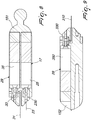
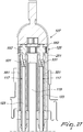
- Figure 6 shows the articulated support 7 in its flexible inactive rest configuration.
- the articulated support 7 of Figure 6 comprises a plurality of rigid bodies 15 that each have a hollow conical end and a convex conical end, with the exception of the terminal rigid bodies 151 and 152, which only have a convex conical end 153.
- the rigid body 154 proximate to the terminal rigid body 152, has both ends 156 that are hollow and conical ends.
- the tensioning cable 23 can be wound, at one of its ends, around a pulley 230 that is keyed to the driving shaft of the motor means 25 arranged in the terminal rigid body 151.
- the tensioning cable 23 passes, in a first direction, through all the rigid bodies 15 and 154, than winds around guiding means 155 arranged in the terminal rigid body 152 and passes again, in a second direction that is opposite the first one, through all the rigid bodies 15 and 154 up to the terminal rigid body 151, to which it is fixed.
- the actuation of the motor means 25 causes the winding of the tensioning cable 23 around the pulley 230 and therefore the mutual approach of the rigid bodies 15, 151, 152 and 154, which, because of the mutually concave and convex conical ends, mate with each other, making the articulated support 7 assume the rigid active configuration.
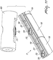
- the articulated support 7 comprises at least one guiding carriage 27, shown in Figures 10 and 11 , which can be associated with at least one between the maneuvering means 9 and the viewing means 21, and translation means 29 adapted to translate the guiding carriage 27 inside the guide 19.
- the articulated support 7 comprises as many guiding carriages 27 as there are maneuvering means 9 and viewing means 21 comprised in the robot 1.
- the translation means 29 comprise at least one translation cable 31, which is connected at a first end to the guiding carriage 27 and can be wound, at the opposite end, around a pulley 33 that is keyed to the driving shaft of motor means 35.
- the translation means 29 comprise two translation cables 31, 310, which are connected respectively to the opposite ends of the guiding carriage 27.
- the first translation cable 31 is actuated by the motor means 35 arranged in the terminal rigid body 151.
- the second translation cable 310 is actuated by motor means 350 arranged in the terminal rigid body 152.
- the motor means 35 and 350 are actuated alternatively and in a coordination manner so as to allow the translation of the guiding carriage 27 in the guide 19, in both directions.
- the motor means 350 also actuate a driving shaft to which a pulley 330 is keyed, the end of the translation cable 310 that is opposite the end connected to the guiding carriage 27 being wound around said pulley 330.
- the translation means 29 can comprise an electromagnetic linear actuator, which comprises a system of permanent magnets and electromagnets conveniently supplied electrically in order to determine the movement of the guiding carriages 27 inside the guide 19.
- the robot 1 can comprise advantageously viewing means 21, which also can be associated slidingly with the guide 19 of the articulated body 7, for example by means of the engagement systems 71, 73 adapted to engage the guiding carriage 27.
- These viewing means 21 can be moved along the guide 19, independently of the movement of the maneuvering means 9, manually by an operator, by remote control or autonomously.
- the viewing means 21 can comprise advantageously multiple video cameras, in order to ensure stereoscopic viewing, advantageously capable of performing pan and tilt motions, in order to provide a clear, wide and three-dimensional view of the surgical area of interest.
- the robot 1 comprises advantageously also lightning devices, such as LED devices.
- the viewing means 21 have advantageously, as shown respectively in Figures 14 and 15 , a closed rest configuration and an open active configuration, in which the video cameras are spaced so as to ensure a three-dimensional stereoscopic reconstruction of the surgical area.
- said viewing means 21a are incorporated inside one of the rigid bodies 15.
- the viewing means 21a are arranged in a suitable receptacle 211 formed in the rigid body 15, so as to remain compressed in the lateral surface of said rigid body 15 without needing any further installation procedure on the articulated support 7.
- the central body 212 is oriented conveniently toward the area of interest inside the surgical area, while two lateral wings 213, which contain the video cameras, open laterally, so as to allow stereoscopic viewing and recording of the imagines.
- the viewing means 21a can also comprise lighting devices 216, preferably integrated in the central body 212, adapted to illuminate the surgical area.
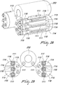
- Figures 11 and 12 show the systems for engaging the maneuvering means 9, and particularly their supporting element 93, with the articulated support 7.
- the guiding carriage 27 that can slide in the guide 19 of the articulated support 7 comprises a ring element 70 adapted to engage a corresponding ring element 71 of the supporting element 93.
- a blocking system is advantageously associated with this ring coupling 70, 71 and comprises an engagement pin 73 associated with the supporting body 93 and a hole 72, associated to the articulated support 7 and adapted to accommodate the engagement pin 73.
- This connection allows to fix stably and rigidly the maneuvering means 9 to the guiding carriage 27 at any mutual angle between the supporting element 93 and the articulated support 7.
- the supporting element 93 contains motor means adapted to actuate the ring coupling 70, 71 and the locking system 72, 73, as described hereinafter.
- the robot 1 can comprise furthermore a plurality of maneuvering means 9, which can be associated with a plurality of operating instruments 11, as well as a plurality of container bodies 13 for said operating instruments 11, and a plurality of viewing means 21, 21a, according to the operating requirements.
- Said different operating modules can operate autonomously with respect to each other while ensuring the coordination needed in order to perform the operation.
- the tensioning cables and/or the translation cables can be actuated by motor means arranged externally with respect to the articulated support 7.
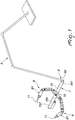
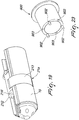
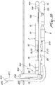
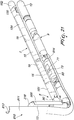
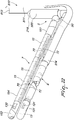
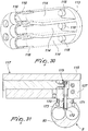
- Figures 20 , 21 and 22 show the maneuvering means 9 and the articulated support 7 during the step of insertion in the surgical area 201. This insertion occurs by virtue of the insertion means 810, which pass through the access opening 200, which is constituted by a single incision or by a natural orifice.
- the insertion means 810 comprise advantageously an insertion guide 811, which is advantageously formed by a substantially tubular structure that is open on one side.
- This insertion guide 811 forms a substantially semicircular channel, in which the maneuvering means 9 and the articulated support 7 can slide, in their flexible rest configuration, as described hereinafter.
- Said insertion guide 811 advantageously has a curved shape in order to facilitate access to the surgical area 201.
- the insertion guide 811 can be formed by a track on which the maneuvering means 9 and the articulated support 7, again in the flexible rest configuration, can engage and slide.
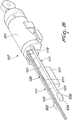
- the insertion means 810 are intended to be arranged with respect to the access opening 200 so that one end 813 is external to the surgical area 201, and therefore accessible to the surgeon, while the opposite end 814 is arranged inside the surgical area 201.
- the adapter 5 (shown only partially) that supports the articulated support 7 can have a terminal portion 500 that has a substantially tubular structure that is open at one end.
- This terminal portion 500 of the adapter 5 provides a second semicircular channel which, by facing in cooperation with the semicircular channel formed by the insertion means 810, forms, proximate to the access opening 200, a substantially circular insertion channel through which the maneuvering means 9 can be inserted in the surgical area 201, as described hereinafter.
- the insertion guide 811 is substantially L-shaped. Moreover, said insertion guide 811 can be made of a material of the type of plastic, which can be conveniently deformed according to the requirements and the anatomy of the patient proximate to the surgical area of interest, or made of a material such as metal.
- the insertion guide 811 can be substantially rigid but have one or more flexible bending points, so that it can be shaped according to the need to access the surgical area 201.
- the insertion means 810 can comprise also a mechanical retainer that prevents the further insertion of the articulated support 7 when it has been inserted to a required depth.
- This mechanical retainer can be conveniently actuated manually by the operator.
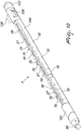
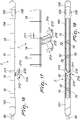
- Figures 24 , 25 and 26 show a variant of the articulated support 107.
- the articulated support 107 comprises at least one guiding carriage 127, which can be associated with at least one between the maneuvering means 9 and the viewing means 21, and translation means adapted to translate the guiding carriage 127 inside a guide 119 defined in the articulated support 107.
- the stiffening means 117 which are associated with the articulated support 107 and are adapted for the transition of the articulated support 107 from a rest configuration to an active configuration, can comprise one or two tensioning elements 123 that pass through the articulated support 107, and more specifically through each one of the rigid bodies 115, 251, 252, 254.
- Such stiffening means 117 can be actuated by actuation means 125.
- the tensioning elements 123 can be tensioning cables.
- the tensioning elements 123 comprise at one of their ends, a threaded body 531, and, at the opposite end, a tensioning body 532.
- the actuation means 125 comprise a threaded tube 551 configured to be rotated around its central axis.
- the threaded body 531 is configured to be moved axially within the threaded tube 551 of the actuation means 125 when the threaded tube 551 is rotated around its own axis.
- the actuation means 125 comprise motor means and transmission gears 552 configured to actuate the rotation of the threaded tube 551.
- the tensioning body 532 of the tensioning elements 123 is configured to abut against a recessed portion 533 of the rigid body 252, so that tensioning of the tensioning elements 123 results in stiffening the whole articulated support 107.
- the tensioning body 532 comprises a flat surface 534 so that any rotation of the tensioning body 532 inside the recessed portion 533 is prevented. Therefore the rotation of the threaded tube 551 results firstly in a sliding movement of the tensioning body 532 inside the recessed portion 533 of the rigid body 252 and then in the stiffening of the articulated support 107.
- the translation means 129 comprise an elongated flexible helical screw 131, which is actuated by actuation means 135 so as to rotate around its longitudinal axis.
- the external surface of the elongated flexible helical screw 131 is configured to engage with a threaded surface 611 of the guiding carriage 127, so that the rotation of the elongated flexible helical screw 131 about its own axis results in the translation of the guiding carriage 127 along the guide 119 of the articulated support, in a "screw and nut mechanism" fashion.
- the articulated support 107 is allowed to assume bent configurations, for example in its flexible rest configuration during insertion into the body cavity.
- the actuation means 135 comprise motor means and transmission gears 652 configured to actuate the rotation of the elongated flexible helical screw 131.
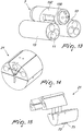
- Figures 31 , 32 and 33 show a variant of the blocking systems for engaging the maneuvering means 9, and particularly their supporting element 93, with the articulated support 107.
- the blocking system comprises an engagement screw 173 associated with the guiding carriage 127 that can slide in the guide 119 of the articulated support 107, and a threaded hole 172 provided in the supporting element 93 and adapted to accommodate the engagement screw 173.
- the engagement screw 173 is actuated by actuation means 175 so that, when the engagement screw 173 engages the threaded hole 172, the supporting element 93 is pulled up towards the guiding carriage 127.
- the guiding carriage 127 can comprise a helical element 170 adapted to engage a corresponding helical element 171 of the supporting element 93.
- the surfaces of the helical elements 170, 171 slide one on the other, so as to force the supporting element 93 to rotate from a position parallel to the articulated support 107, to a position orthogonal to the articulated support, as shown in figures 32 and 33 .
- the angle between the supporting element 93 and the articulated support 107 is a fixed angle of about 90°.
- Figure 33 shows an operative configuration of the robot 1, in which the supporting element 93, and therefore the maneuvering means 9, are positioned at an angle of 90° with respect to the articulated support 107.
- the maneuvering means 9 can be substantially parallel with respect to the articulated support 107, as shown in figure 32 .
- the blocking system is advantageously associated with this helical coupling 170, 171, and comprises an engagement screw 173 associated with the articulated support 107 and a threaded hole 172 provided in the supporting element 93 and adapted to accommodate the engagement screw 173.
- the connection between the screw 173 and the hole 172 allows to fix stably and rigidly the maneuvering means 9 to the guiding carriage 127 at a fixed angle between the supporting element 93 and the articulated support 107.
- Figures 28, 29 ad 30 show a variant of the container body 113, which is adapted to contain up to three instruments 111.
- the container body 113 comprises three slots 114 for accommodating the instruments 111.
- the slots 114 are provided with leaf springs 116, configured to stably hold the instruments 111, and with a safety sensor 118 and a retention spring adapted to check the presence, or absence, of an instrument 111 in the corresponding slot 114.
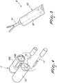
- FIGS 34 and 35 show a variant of the insertion means 910.
- the insertion means 910 comprise advantageously an insertion guide 911, which is advantageously formed by a substantially tubular structure that is open on one side.
- This insertion guide 911 forms a substantially semicircular channel, in which the maneuvering means 9 and the articulated support 7, 107 can slide, in their flexible rest configuration.
- the insertion means 910 comprise a plurality of rigid elements 912, reciprocally hinged one to another so as to define the insertion guide 911.
- the insertion means 910 also comprise tensioning cables 917, provided with cable stoppers 918, that pass through holes 919 provided in all the rigid elements 912. Such tensioning cables are configured to rigidify the insertion guide 911, or portions thereof, when required.
- the insertion means 910 comprise motor means 914, provided with pulley 915 around which the tensioning cables 917 can wind up, in order to stiffen the whole structure, or portions thereof.
- the insertion guide 911 can assume a substantially L-shaped configuration.
- the above-mentioned portions of the guide 911 can bee steered independently by means of the tensioning cables 917, in order to insert the insertion guide 911 in a body cavity without touching inner body parts.
- the surgeon performs an incision, or prepares the natural orifice, that forms the access opening 200, through which a trocar, possibly provided with viewing means, is inserted. Then the surgical cavity is inflated.
- the terminal end of the trocar 900 is shown in Figure 23 .
- said trocar 900 can have lighting means 901, such as for example LEDs, and viewing means 902, such as video cameras.
- the surgeon inserts the insertion means 810 in the surgical area 201.
- the articulated support 7 is inserted in the flexible rest configuration, making it slide along the guide formed by the insertion means 810.
- the correct insertion of the articulated support 7 along the guide formed by the insertion means 810 is indicated by means of calibrated reference points provided on the insertion means 810 and on said articulated support 7.
- a mechanical retainer is provided which can be activated manually by the operator and blocks the insertion of the articulated support 7 along the insertion means 810 when they have reached the predefined position.
- the articulated support 7 can be then connected, if it is not already, to the terminal portion 500 of the adapter 5 by means of the spherical hinge 50 and said adapter 5 is supported by the supporting structure 3, fixed to the operating table.
- stiffening means 17 are activated and bring the articulated support 7 in its active rigid configuration, locking also the spherical hinge 50, which therefore becomes a rigid coupling.
- the insertion guide 811 and the terminal portion 500 of the adapter 5 provide at this point a channel formed by two semicircular channels which straddle the access opening 200 of the surgical area 201.
- the maneuvering means 9, in their rest configuration, i.e. flexible configuration, are then inserted in the surgical area 201. They are inserted initially through the channel formed by the insertion means 810 and by the terminal portion 500 of the adapter 5, and then are made to slide along the insertion guide 811, moving beyond also the terminal end portion 814.
- the insertion of the maneuvering means 9 also is assisted by the presence of calibrated reference points that are present not only on the insertion means 810 but also on said maneuvering means 9.
- the articulated support 7 and the maneuvering means 9 once inserted in the surgical area 201 and brought to the rigid active configuration, are in a position in which the engagement means 70, 72 of the articulated support 7 face the engagement means 71, 73 of the maneuvering means 9.
- maneuvering means 9 are moved into contact with the articulated support 7 so as to engage mutually by means of the respective engaging systems.
- the operation for mutual approach of the maneuvering means 9 and the articulated support 7 can be performed manually by the surgeon, who pulls toward himself the end 218 of the maneuvering means 9 that is still accessible from the outside of the access opening 200, or pulls toward himself the insertion means 810 on which the freshly inserted maneuvering means 9 rest.
- actuation and engagement means can consist for example of a screw, which is driven by a motor, is arranged in the maneuvering means 9 and engages a threaded hole provided in the articulated support 7.
- the translation means 29 are actuated and move said maneuvering means 9 along the guide 19 of the articulated support 7, so that said maneuvering means 9 are inserted completely in the surgical area 201 and reach a desired position along the guide 19.
- this removal of the insertion means 810 can occur when the maneuvering means 9 have been moved along the guide 19 in a position of noninterference with the terminal end portion 814 of the insertion guide 811.
- the maneuvering means 9, which still lie substantially parallel to the articulated support 7, can now been conveniently rotated, for example through 90°, by means of the engagement systems 70, 71, 72 and 73, so that the articulated support 7 and the maneuvering means 9 assume a relative configuration such as the one shown in Figure 1 . Once they have been engaged with the articulated support 7, the maneuvering means 9 in fact are activated, passing from the rest configuration to the active configuration.
- the assembly of the robot 1 also entails a step for engaging the container bodies 13 with the articulated support 7.
- This step entails the opening of the engagement tab 130 arranged at the end of the articulated support 7, the actuation of the maneuvering means 9 so that they move closer and engage the engagement tabs 130 in the engagement slots 131 formed in the container bodies 13, and the subsequent release of the container bodies 13 from the maneuvering means 9, once they have been stably engaged with the articulated support 7.
- the viewing means 21, 21a are advantageously active, i.e., in the open operating configuration.
- the operator can proceed with the activation of the maneuvering means 9, by moving the robotic arms 91 in order to arrange and engage with the articulated support 7 the container bodies 13, which are still engaged with the maneuvering means 9 when the surgical area 201 is viewed by the viewing means 21, 21a.
- the maneuvering means 9 extract the required operating instruments 11 from the available container bodies 13, which are now engaged with the articulated support 7, and perform the surgical operation.
- any pathological tissues to be removed are extracted and removed from the surgical area and one can then proceed with the extraction of the robot 1 in reverse order with respect to the order of insertion.
- Removal of the robot 1 from the surgical area 201 occurs by bringing the articulated support 7 and the maneuvering means 9 to their inactive flexible configuration.
- the articulated support 7 and the maneuvering means 9 can be therefore grabbed by the operator by means of a suitable forceps or similar instrument that passes through the trocar, and then extracted.
- the procedure for changing operating instrument 11 is as follows: the forearms 97 of the robotic arm 91 are aligned with the container body 13 engaged with the articulated support 7. At this point the translational movements along the guide 19 of the maneuvering means 9 and the rotational movements of the wrist-like joint of the robotic arm 91 are used in order to move closer and engage the desired operating instrument 11. During this operation, the safety devices ensure that each operating instrument 11 is always associated with the respective container body 13, or with the maneuvering means 9, or with both at the same time.
- the robot particularly for mini-invasive surgery achieves the intended aim and objects, since it allows to perform mini-invasive surgical operations in a manner that is safe for the patient without requiring a plurality of accesses to the surgical area of interest.
- Another advantage of the robot according to the invention is that it has small dimensions and is easy to handle and therefore also fast and easy to insert and remove.
- a further advantage of the robot according to the invention is that it can be equipped with a plurality of different operating instruments in order to perform various surgical operations.
- Another advantage of the robot according to the invention is that it can be also used in combination with laparoscopic techniques of the standard type, since it does not occupy the surgical surface of the abdomen or of the chest with bulky devices.
- a further advantage of the robot according to the invention is that it offers the stability and stiffness needed to transmit and apply forces and moments necessary for the surgical operation.
- the materials used may be any according to the requirements.
Landscapes
- Health & Medical Sciences (AREA)
- Life Sciences & Earth Sciences (AREA)
- Surgery (AREA)
- Engineering & Computer Science (AREA)
- Animal Behavior & Ethology (AREA)
- Veterinary Medicine (AREA)
- Biomedical Technology (AREA)
- Heart & Thoracic Surgery (AREA)
- Medical Informatics (AREA)
- Molecular Biology (AREA)
- Nuclear Medicine, Radiotherapy & Molecular Imaging (AREA)
- General Health & Medical Sciences (AREA)
- Public Health (AREA)
- Pathology (AREA)
- Physics & Mathematics (AREA)
- Biophysics (AREA)
- Optics & Photonics (AREA)
- Radiology & Medical Imaging (AREA)
- Robotics (AREA)
- Oral & Maxillofacial Surgery (AREA)
- Manipulator (AREA)
- Materials For Medical Uses (AREA)
Applications Claiming Priority (2)
| Application Number | Priority Date | Filing Date | Title |
|---|---|---|---|
| IT000666A ITMI20130666A1 (it) | 2013-04-23 | 2013-04-23 | Struttura di robot, particolarmente per chirurgia mini-invasiva attraverso singola incisione parietale o orifizio naturale. |
| PCT/EP2014/058199 WO2014173932A1 (en) | 2013-04-23 | 2014-04-23 | Robot, particularly for mini-invasive surgery through a single parietal incision or natural orifice |
Publications (2)
| Publication Number | Publication Date |
|---|---|
| EP2988694A1 EP2988694A1 (en) | 2016-03-02 |
| EP2988694B1 true EP2988694B1 (en) | 2020-04-29 |
Family
ID=48579268
Family Applications (1)
| Application Number | Title | Priority Date | Filing Date |
|---|---|---|---|
| EP14718985.6A Active EP2988694B1 (en) | 2013-04-23 | 2014-04-23 | Robot, particularly for mini-invasive surgery through a single parietal incision or natural orifice |
Country Status (5)
| Country | Link |
|---|---|
| US (1) | US10675102B2 (es) |
| EP (1) | EP2988694B1 (es) |
| ES (1) | ES2802884T3 (es) |
| IT (1) | ITMI20130666A1 (es) |
| WO (1) | WO2014173932A1 (es) |
Families Citing this family (264)
| Publication number | Priority date | Publication date | Assignee | Title |
|---|---|---|---|---|
| US9060770B2 (en) | 2003-05-20 | 2015-06-23 | Ethicon Endo-Surgery, Inc. | Robotically-driven surgical instrument with E-beam driver |
| US20070084897A1 (en) | 2003-05-20 | 2007-04-19 | Shelton Frederick E Iv | Articulating surgical stapling instrument incorporating a two-piece e-beam firing mechanism |
| US11896225B2 (en) | 2004-07-28 | 2024-02-13 | Cilag Gmbh International | Staple cartridge comprising a pan |
| US11484312B2 (en) | 2005-08-31 | 2022-11-01 | Cilag Gmbh International | Staple cartridge comprising a staple driver arrangement |
| US8991676B2 (en) | 2007-03-15 | 2015-03-31 | Ethicon Endo-Surgery, Inc. | Surgical staple having a slidable crown |
| US7934630B2 (en) | 2005-08-31 | 2011-05-03 | Ethicon Endo-Surgery, Inc. | Staple cartridges for forming staples having differing formed staple heights |
| US7669746B2 (en) | 2005-08-31 | 2010-03-02 | Ethicon Endo-Surgery, Inc. | Staple cartridges for forming staples having differing formed staple heights |
| US10159482B2 (en) | 2005-08-31 | 2018-12-25 | Ethicon Llc | Fastener cartridge assembly comprising a fixed anvil and different staple heights |
| US11246590B2 (en) | 2005-08-31 | 2022-02-15 | Cilag Gmbh International | Staple cartridge including staple drivers having different unfired heights |
| US20070106317A1 (en) | 2005-11-09 | 2007-05-10 | Shelton Frederick E Iv | Hydraulically and electrically actuated articulation joints for surgical instruments |
| US11278279B2 (en) | 2006-01-31 | 2022-03-22 | Cilag Gmbh International | Surgical instrument assembly |
| US8708213B2 (en) | 2006-01-31 | 2014-04-29 | Ethicon Endo-Surgery, Inc. | Surgical instrument having a feedback system |
| US8186555B2 (en) | 2006-01-31 | 2012-05-29 | Ethicon Endo-Surgery, Inc. | Motor-driven surgical cutting and fastening instrument with mechanical closure system |
| US8820603B2 (en) | 2006-01-31 | 2014-09-02 | Ethicon Endo-Surgery, Inc. | Accessing data stored in a memory of a surgical instrument |
| US7753904B2 (en) | 2006-01-31 | 2010-07-13 | Ethicon Endo-Surgery, Inc. | Endoscopic surgical instrument with a handle that can articulate with respect to the shaft |
| US7845537B2 (en) | 2006-01-31 | 2010-12-07 | Ethicon Endo-Surgery, Inc. | Surgical instrument having recording capabilities |
| US20120292367A1 (en) | 2006-01-31 | 2012-11-22 | Ethicon Endo-Surgery, Inc. | Robotically-controlled end effector |
| US20110295295A1 (en) | 2006-01-31 | 2011-12-01 | Ethicon Endo-Surgery, Inc. | Robotically-controlled surgical instrument having recording capabilities |
| US11793518B2 (en) | 2006-01-31 | 2023-10-24 | Cilag Gmbh International | Powered surgical instruments with firing system lockout arrangements |
| US8992422B2 (en) | 2006-03-23 | 2015-03-31 | Ethicon Endo-Surgery, Inc. | Robotically-controlled endoscopic accessory channel |
| US10568652B2 (en) | 2006-09-29 | 2020-02-25 | Ethicon Llc | Surgical staples having attached drivers of different heights and stapling instruments for deploying the same |
| US11980366B2 (en) | 2006-10-03 | 2024-05-14 | Cilag Gmbh International | Surgical instrument |
| US11291441B2 (en) | 2007-01-10 | 2022-04-05 | Cilag Gmbh International | Surgical instrument with wireless communication between control unit and remote sensor |
| US8652120B2 (en) | 2007-01-10 | 2014-02-18 | Ethicon Endo-Surgery, Inc. | Surgical instrument with wireless communication between control unit and sensor transponders |
| US8684253B2 (en) | 2007-01-10 | 2014-04-01 | Ethicon Endo-Surgery, Inc. | Surgical instrument with wireless communication between a control unit of a robotic system and remote sensor |
| US20080169332A1 (en) | 2007-01-11 | 2008-07-17 | Shelton Frederick E | Surgical stapling device with a curved cutting member |
| US11672531B2 (en) | 2007-06-04 | 2023-06-13 | Cilag Gmbh International | Rotary drive systems for surgical instruments |
| US8931682B2 (en) | 2007-06-04 | 2015-01-13 | Ethicon Endo-Surgery, Inc. | Robotically-controlled shaft based rotary drive systems for surgical instruments |
| US11849941B2 (en) | 2007-06-29 | 2023-12-26 | Cilag Gmbh International | Staple cartridge having staple cavities extending at a transverse angle relative to a longitudinal cartridge axis |
| US8636736B2 (en) | 2008-02-14 | 2014-01-28 | Ethicon Endo-Surgery, Inc. | Motorized surgical cutting and fastening instrument |
| US11986183B2 (en) | 2008-02-14 | 2024-05-21 | Cilag Gmbh International | Surgical cutting and fastening instrument comprising a plurality of sensors to measure an electrical parameter |
| US7866527B2 (en) | 2008-02-14 | 2011-01-11 | Ethicon Endo-Surgery, Inc. | Surgical stapling apparatus with interlockable firing system |
| RU2493788C2 (ru) | 2008-02-14 | 2013-09-27 | Этикон Эндо-Серджери, Инк. | Хирургический режущий и крепежный инструмент, имеющий радиочастотные электроды |
| US9179912B2 (en) | 2008-02-14 | 2015-11-10 | Ethicon Endo-Surgery, Inc. | Robotically-controlled motorized surgical cutting and fastening instrument |
| US7819298B2 (en) | 2008-02-14 | 2010-10-26 | Ethicon Endo-Surgery, Inc. | Surgical stapling apparatus with control features operable with one hand |
| US8210411B2 (en) | 2008-09-23 | 2012-07-03 | Ethicon Endo-Surgery, Inc. | Motor-driven surgical cutting instrument |
| US9386983B2 (en) | 2008-09-23 | 2016-07-12 | Ethicon Endo-Surgery, Llc | Robotically-controlled motorized surgical instrument |
| US11648005B2 (en) | 2008-09-23 | 2023-05-16 | Cilag Gmbh International | Robotically-controlled motorized surgical instrument with an end effector |
| US9005230B2 (en) | 2008-09-23 | 2015-04-14 | Ethicon Endo-Surgery, Inc. | Motorized surgical instrument |
| US8608045B2 (en) | 2008-10-10 | 2013-12-17 | Ethicon Endo-Sugery, Inc. | Powered surgical cutting and stapling apparatus with manually retractable firing system |
| US11849952B2 (en) | 2010-09-30 | 2023-12-26 | Cilag Gmbh International | Staple cartridge comprising staples positioned within a compressible portion thereof |
| US9282962B2 (en) | 2010-09-30 | 2016-03-15 | Ethicon Endo-Surgery, Llc | Adhesive film laminate |
| US11812965B2 (en) | 2010-09-30 | 2023-11-14 | Cilag Gmbh International | Layer of material for a surgical end effector |
| US9351730B2 (en) | 2011-04-29 | 2016-05-31 | Ethicon Endo-Surgery, Llc | Tissue thickness compensator comprising channels |
| US9629814B2 (en) | 2010-09-30 | 2017-04-25 | Ethicon Endo-Surgery, Llc | Tissue thickness compensator configured to redistribute compressive forces |
| US9320523B2 (en) | 2012-03-28 | 2016-04-26 | Ethicon Endo-Surgery, Llc | Tissue thickness compensator comprising tissue ingrowth features |
| US11298125B2 (en) | 2010-09-30 | 2022-04-12 | Cilag Gmbh International | Tissue stapler having a thickness compensator |
| US10945731B2 (en) | 2010-09-30 | 2021-03-16 | Ethicon Llc | Tissue thickness compensator comprising controlled release and expansion |
| US9168038B2 (en) | 2010-09-30 | 2015-10-27 | Ethicon Endo-Surgery, Inc. | Staple cartridge comprising a tissue thickness compensator |
| US8695866B2 (en) | 2010-10-01 | 2014-04-15 | Ethicon Endo-Surgery, Inc. | Surgical instrument having a power control circuit |
| BR112013027794B1 (pt) | 2011-04-29 | 2020-12-15 | Ethicon Endo-Surgery, Inc | Conjunto de cartucho de grampos |
| US9072535B2 (en) | 2011-05-27 | 2015-07-07 | Ethicon Endo-Surgery, Inc. | Surgical stapling instruments with rotatable staple deployment arrangements |
| US9089353B2 (en) | 2011-07-11 | 2015-07-28 | Board Of Regents Of The University Of Nebraska | Robotic surgical devices, systems, and related methods |
| JP6305979B2 (ja) | 2012-03-28 | 2018-04-04 | エシコン・エンド−サージェリィ・インコーポレイテッドEthicon Endo−Surgery,Inc. | 複数の層を含む組織厚さコンペンセーター |
| BR112014024098B1 (pt) | 2012-03-28 | 2021-05-25 | Ethicon Endo-Surgery, Inc. | cartucho de grampos |
| EP3845190B1 (en) | 2012-05-01 | 2023-07-12 | Board of Regents of the University of Nebraska | Single site robotic device and related systems |
| US9101358B2 (en) | 2012-06-15 | 2015-08-11 | Ethicon Endo-Surgery, Inc. | Articulatable surgical instrument comprising a firing drive |
| US20140001231A1 (en) | 2012-06-28 | 2014-01-02 | Ethicon Endo-Surgery, Inc. | Firing system lockout arrangements for surgical instruments |
| US9289256B2 (en) | 2012-06-28 | 2016-03-22 | Ethicon Endo-Surgery, Llc | Surgical end effectors having angled tissue-contacting surfaces |
| US9649111B2 (en) | 2012-06-28 | 2017-05-16 | Ethicon Endo-Surgery, Llc | Replaceable clip cartridge for a clip applier |
| US9226751B2 (en) | 2012-06-28 | 2016-01-05 | Ethicon Endo-Surgery, Inc. | Surgical instrument system including replaceable end effectors |
| BR112014032776B1 (pt) | 2012-06-28 | 2021-09-08 | Ethicon Endo-Surgery, Inc | Sistema de instrumento cirúrgico e kit cirúrgico para uso com um sistema de instrumento cirúrgico |
| WO2014025399A1 (en) | 2012-08-08 | 2014-02-13 | Board Of Regents Of The University Of Nebraska | Robotic surgical devices, systems, and related methods |
| RU2669463C2 (ru) | 2013-03-01 | 2018-10-11 | Этикон Эндо-Серджери, Инк. | Хирургический инструмент с мягким упором |
| MX368026B (es) | 2013-03-01 | 2019-09-12 | Ethicon Endo Surgery Inc | Instrumento quirúrgico articulable con vías conductoras para la comunicación de la señal. |
| US9629629B2 (en) | 2013-03-14 | 2017-04-25 | Ethicon Endo-Surgey, LLC | Control systems for surgical instruments |
| BR112015026109B1 (pt) | 2013-04-16 | 2022-02-22 | Ethicon Endo-Surgery, Inc | Instrumento cirúrgico |
| US9867612B2 (en) | 2013-04-16 | 2018-01-16 | Ethicon Llc | Powered surgical stapler |
| JP6479790B2 (ja) | 2013-07-17 | 2019-03-06 | ボード オブ リージェンツ オブ ザ ユニバーシティ オブ ネブラスカ | ロボット外科的デバイス、システムおよび関連する方法 |
| RU2678363C2 (ru) | 2013-08-23 | 2019-01-28 | ЭТИКОН ЭНДО-СЕРДЖЕРИ, ЭлЭлСи | Устройства втягивания пускового элемента для хирургических инструментов с электропитанием |
| US20150053743A1 (en) | 2013-08-23 | 2015-02-26 | Ethicon Endo-Surgery, Inc. | Error detection arrangements for surgical instrument assemblies |
| US9804618B2 (en) | 2014-03-26 | 2017-10-31 | Ethicon Llc | Systems and methods for controlling a segmented circuit |
| US20150297225A1 (en) | 2014-04-16 | 2015-10-22 | Ethicon Endo-Surgery, Inc. | Fastener cartridges including extensions having different configurations |
| JP6532889B2 (ja) | 2014-04-16 | 2019-06-19 | エシコン エルエルシーEthicon LLC | 締結具カートリッジ組立体及びステープル保持具カバー配置構成 |
| JP6636452B2 (ja) | 2014-04-16 | 2020-01-29 | エシコン エルエルシーEthicon LLC | 異なる構成を有する延在部を含む締結具カートリッジ |
| JP6612256B2 (ja) | 2014-04-16 | 2019-11-27 | エシコン エルエルシー | 不均一な締結具を備える締結具カートリッジ |
| US11311294B2 (en) | 2014-09-05 | 2022-04-26 | Cilag Gmbh International | Powered medical device including measurement of closure state of jaws |
| US10016199B2 (en) | 2014-09-05 | 2018-07-10 | Ethicon Llc | Polarity of hall magnet to identify cartridge type |
| BR112017004361B1 (pt) | 2014-09-05 | 2023-04-11 | Ethicon Llc | Sistema eletrônico para um instrumento cirúrgico |
| US11523821B2 (en) | 2014-09-26 | 2022-12-13 | Cilag Gmbh International | Method for creating a flexible staple line |
| US9924944B2 (en) | 2014-10-16 | 2018-03-27 | Ethicon Llc | Staple cartridge comprising an adjunct material |
| US11141153B2 (en) | 2014-10-29 | 2021-10-12 | Cilag Gmbh International | Staple cartridges comprising driver arrangements |
| US10517594B2 (en) | 2014-10-29 | 2019-12-31 | Ethicon Llc | Cartridge assemblies for surgical staplers |
| US9844376B2 (en) | 2014-11-06 | 2017-12-19 | Ethicon Llc | Staple cartridge comprising a releasable adjunct material |
| US10736636B2 (en) | 2014-12-10 | 2020-08-11 | Ethicon Llc | Articulatable surgical instrument system |
| US10085748B2 (en) | 2014-12-18 | 2018-10-02 | Ethicon Llc | Locking arrangements for detachable shaft assemblies with articulatable surgical end effectors |
| US9987000B2 (en) | 2014-12-18 | 2018-06-05 | Ethicon Llc | Surgical instrument assembly comprising a flexible articulation system |
| MX2017008108A (es) | 2014-12-18 | 2018-03-06 | Ethicon Llc | Instrumento quirurgico con un yunque que puede moverse de manera selectiva sobre un eje discreto no movil con relacion a un cartucho de grapas. |
| US10245027B2 (en) | 2014-12-18 | 2019-04-02 | Ethicon Llc | Surgical instrument with an anvil that is selectively movable about a discrete non-movable axis relative to a staple cartridge |
| US9844375B2 (en) | 2014-12-18 | 2017-12-19 | Ethicon Llc | Drive arrangements for articulatable surgical instruments |
| US9844374B2 (en) | 2014-12-18 | 2017-12-19 | Ethicon Llc | Surgical instrument systems comprising an articulatable end effector and means for adjusting the firing stroke of a firing member |
| US11154301B2 (en) | 2015-02-27 | 2021-10-26 | Cilag Gmbh International | Modular stapling assembly |
| JP2020121162A (ja) | 2015-03-06 | 2020-08-13 | エシコン エルエルシーEthicon LLC | 測定の安定性要素、クリープ要素、及び粘弾性要素を決定するためのセンサデータの時間依存性評価 |
| US10441279B2 (en) | 2015-03-06 | 2019-10-15 | Ethicon Llc | Multiple level thresholds to modify operation of powered surgical instruments |
| US9993248B2 (en) | 2015-03-06 | 2018-06-12 | Ethicon Endo-Surgery, Llc | Smart sensors with local signal processing |
| US10052044B2 (en) | 2015-03-06 | 2018-08-21 | Ethicon Llc | Time dependent evaluation of sensor data to determine stability, creep, and viscoelastic elements of measures |
| US10433844B2 (en) | 2015-03-31 | 2019-10-08 | Ethicon Llc | Surgical instrument with selectively disengageable threaded drive systems |
| MA44324A (fr) * | 2015-06-29 | 2018-05-02 | Fundacio Inst Dinvestigacio En Ciencies De La Salut Germans Trias I Pujol | Dispositifs d'éclairage ou d'assistance dans une procédure médicale |
| CN114027986A (zh) | 2015-08-03 | 2022-02-11 | 内布拉斯加大学董事会 | 机器人手术装置系统及相关方法 |
| US10238386B2 (en) | 2015-09-23 | 2019-03-26 | Ethicon Llc | Surgical stapler having motor control based on an electrical parameter related to a motor current |
| US10105139B2 (en) | 2015-09-23 | 2018-10-23 | Ethicon Llc | Surgical stapler having downstream current-based motor control |
| US11890015B2 (en) | 2015-09-30 | 2024-02-06 | Cilag Gmbh International | Compressible adjunct with crossing spacer fibers |
| US10271849B2 (en) | 2015-09-30 | 2019-04-30 | Ethicon Llc | Woven constructs with interlocked standing fibers |
| US10292704B2 (en) | 2015-12-30 | 2019-05-21 | Ethicon Llc | Mechanisms for compensating for battery pack failure in powered surgical instruments |
| US11213293B2 (en) | 2016-02-09 | 2022-01-04 | Cilag Gmbh International | Articulatable surgical instruments with single articulation link arrangements |
| CN108882932B (zh) | 2016-02-09 | 2021-07-23 | 伊西康有限责任公司 | 具有非对称关节运动构造的外科器械 |
| EP3413831B1 (en) | 2016-02-11 | 2022-11-09 | Valuebiotech S.r.l. | Guiding and support device, particularly for a robot for minimally-invasive surgery through a single parietal incision and/or natural orifice |
| US11224426B2 (en) | 2016-02-12 | 2022-01-18 | Cilag Gmbh International | Mechanisms for compensating for drivetrain failure in powered surgical instruments |
| US10448948B2 (en) | 2016-02-12 | 2019-10-22 | Ethicon Llc | Mechanisms for compensating for drivetrain failure in powered surgical instruments |
| US10828028B2 (en) | 2016-04-15 | 2020-11-10 | Ethicon Llc | Surgical instrument with multiple program responses during a firing motion |
| US10426467B2 (en) | 2016-04-15 | 2019-10-01 | Ethicon Llc | Surgical instrument with detection sensors |
| US10357247B2 (en) | 2016-04-15 | 2019-07-23 | Ethicon Llc | Surgical instrument with multiple program responses during a firing motion |
| US11607239B2 (en) | 2016-04-15 | 2023-03-21 | Cilag Gmbh International | Systems and methods for controlling a surgical stapling and cutting instrument |
| US10492783B2 (en) | 2016-04-15 | 2019-12-03 | Ethicon, Llc | Surgical instrument with improved stop/start control during a firing motion |
| US11317917B2 (en) | 2016-04-18 | 2022-05-03 | Cilag Gmbh International | Surgical stapling system comprising a lockable firing assembly |
| US10368867B2 (en) | 2016-04-18 | 2019-08-06 | Ethicon Llc | Surgical instrument comprising a lockout |
| US20170296173A1 (en) | 2016-04-18 | 2017-10-19 | Ethicon Endo-Surgery, Llc | Method for operating a surgical instrument |
| WO2017201310A1 (en) | 2016-05-18 | 2017-11-23 | Virtual Incision Corporation | Robotic surgicla devices, systems and related methods |
| JP7010956B2 (ja) | 2016-12-21 | 2022-01-26 | エシコン エルエルシー | 組織をステープル留めする方法 |
| US20180168615A1 (en) | 2016-12-21 | 2018-06-21 | Ethicon Endo-Surgery, Llc | Method of deforming staples from two different types of staple cartridges with the same surgical stapling instrument |
| US10813638B2 (en) | 2016-12-21 | 2020-10-27 | Ethicon Llc | Surgical end effectors with expandable tissue stop arrangements |
| US11090048B2 (en) | 2016-12-21 | 2021-08-17 | Cilag Gmbh International | Method for resetting a fuse of a surgical instrument shaft |
| US11419606B2 (en) | 2016-12-21 | 2022-08-23 | Cilag Gmbh International | Shaft assembly comprising a clutch configured to adapt the output of a rotary firing member to two different systems |
| US10835245B2 (en) | 2016-12-21 | 2020-11-17 | Ethicon Llc | Method for attaching a shaft assembly to a surgical instrument and, alternatively, to a surgical robot |
| US10603036B2 (en) | 2016-12-21 | 2020-03-31 | Ethicon Llc | Articulatable surgical instrument with independent pivotable linkage distal of an articulation lock |
| CN110099619B (zh) | 2016-12-21 | 2022-07-15 | 爱惜康有限责任公司 | 用于外科端部执行器和可替换工具组件的闭锁装置 |
| US10588632B2 (en) | 2016-12-21 | 2020-03-17 | Ethicon Llc | Surgical end effectors and firing members thereof |
| US20180168625A1 (en) | 2016-12-21 | 2018-06-21 | Ethicon Endo-Surgery, Llc | Surgical stapling instruments with smart staple cartridges |
| US10881399B2 (en) | 2017-06-20 | 2021-01-05 | Ethicon Llc | Techniques for adaptive control of motor velocity of a surgical stapling and cutting instrument |
| US10307170B2 (en) | 2017-06-20 | 2019-06-04 | Ethicon Llc | Method for closed loop control of motor velocity of a surgical stapling and cutting instrument |
| US11653914B2 (en) | 2017-06-20 | 2023-05-23 | Cilag Gmbh International | Systems and methods for controlling motor velocity of a surgical stapling and cutting instrument according to articulation angle of end effector |
| US10779820B2 (en) | 2017-06-20 | 2020-09-22 | Ethicon Llc | Systems and methods for controlling motor speed according to user input for a surgical instrument |
| US11517325B2 (en) | 2017-06-20 | 2022-12-06 | Cilag Gmbh International | Closed loop feedback control of motor velocity of a surgical stapling and cutting instrument based on measured displacement distance traveled over a specified time interval |
| US11382638B2 (en) | 2017-06-20 | 2022-07-12 | Cilag Gmbh International | Closed loop feedback control of motor velocity of a surgical stapling and cutting instrument based on measured time over a specified displacement distance |
| US10993716B2 (en) | 2017-06-27 | 2021-05-04 | Ethicon Llc | Surgical anvil arrangements |
| US11324503B2 (en) | 2017-06-27 | 2022-05-10 | Cilag Gmbh International | Surgical firing member arrangements |
| US10765427B2 (en) | 2017-06-28 | 2020-09-08 | Ethicon Llc | Method for articulating a surgical instrument |
| EP4070740A1 (en) | 2017-06-28 | 2022-10-12 | Cilag GmbH International | Surgical instrument comprising selectively actuatable rotatable couplers |
| USD906355S1 (en) | 2017-06-28 | 2020-12-29 | Ethicon Llc | Display screen or portion thereof with a graphical user interface for a surgical instrument |
| US11564686B2 (en) | 2017-06-28 | 2023-01-31 | Cilag Gmbh International | Surgical shaft assemblies with flexible interfaces |
| US11020114B2 (en) | 2017-06-28 | 2021-06-01 | Cilag Gmbh International | Surgical instruments with articulatable end effector with axially shortened articulation joint configurations |
| US11484310B2 (en) | 2017-06-28 | 2022-11-01 | Cilag Gmbh International | Surgical instrument comprising a shaft including a closure tube profile |
| US10932772B2 (en) | 2017-06-29 | 2021-03-02 | Ethicon Llc | Methods for closed loop velocity control for robotic surgical instrument |
| US11304695B2 (en) | 2017-08-03 | 2022-04-19 | Cilag Gmbh International | Surgical system shaft interconnection |
| US11944300B2 (en) | 2017-08-03 | 2024-04-02 | Cilag Gmbh International | Method for operating a surgical system bailout |
| US11974742B2 (en) | 2017-08-03 | 2024-05-07 | Cilag Gmbh International | Surgical system comprising an articulation bailout |
| US11471155B2 (en) | 2017-08-03 | 2022-10-18 | Cilag Gmbh International | Surgical system bailout |
| WO2019067763A1 (en) | 2017-09-27 | 2019-04-04 | Virtual Incision Corporation | ROBOTISED SURGICAL DEVICES WITH TRACKING CAMERA TECHNOLOGY AND RELATED SYSTEMS AND METHODS |
| US10842490B2 (en) | 2017-10-31 | 2020-11-24 | Ethicon Llc | Cartridge body design with force reduction based on firing completion |
| US10779826B2 (en) | 2017-12-15 | 2020-09-22 | Ethicon Llc | Methods of operating surgical end effectors |
| US10835330B2 (en) | 2017-12-19 | 2020-11-17 | Ethicon Llc | Method for determining the position of a rotatable jaw of a surgical instrument attachment assembly |
| US11311290B2 (en) | 2017-12-21 | 2022-04-26 | Cilag Gmbh International | Surgical instrument comprising an end effector dampener |
| US11751867B2 (en) | 2017-12-21 | 2023-09-12 | Cilag Gmbh International | Surgical instrument comprising sequenced systems |
| CN111770816B (zh) | 2018-01-05 | 2023-11-03 | 内布拉斯加大学董事会 | 具有紧凑型关节设计的单臂机器人装置及相关系统和方法 |
| US11931017B2 (en) | 2018-06-04 | 2024-03-19 | Valuebiotech Israel Ltd. | Actuation connector for a tool |
| US11207065B2 (en) | 2018-08-20 | 2021-12-28 | Cilag Gmbh International | Method for fabricating surgical stapler anvils |
| US11324501B2 (en) | 2018-08-20 | 2022-05-10 | Cilag Gmbh International | Surgical stapling devices with improved closure members |
| EP3908171A4 (en) * | 2019-01-07 | 2022-09-14 | Virtual Incision Corporation | ROBOTIZED ASSISTED SURGICAL SYSTEM AND RELATED DEVICES AND PROCEDURES |
| US11696761B2 (en) | 2019-03-25 | 2023-07-11 | Cilag Gmbh International | Firing drive arrangements for surgical systems |
| US11648009B2 (en) | 2019-04-30 | 2023-05-16 | Cilag Gmbh International | Rotatable jaw tip for a surgical instrument |
| US11471157B2 (en) | 2019-04-30 | 2022-10-18 | Cilag Gmbh International | Articulation control mapping for a surgical instrument |
| US11452528B2 (en) | 2019-04-30 | 2022-09-27 | Cilag Gmbh International | Articulation actuators for a surgical instrument |
| US11432816B2 (en) | 2019-04-30 | 2022-09-06 | Cilag Gmbh International | Articulation pin for a surgical instrument |
| US11903581B2 (en) | 2019-04-30 | 2024-02-20 | Cilag Gmbh International | Methods for stapling tissue using a surgical instrument |
| US11253254B2 (en) | 2019-04-30 | 2022-02-22 | Cilag Gmbh International | Shaft rotation actuator on a surgical instrument |
| US11426251B2 (en) | 2019-04-30 | 2022-08-30 | Cilag Gmbh International | Articulation directional lights on a surgical instrument |
| US11853835B2 (en) | 2019-06-28 | 2023-12-26 | Cilag Gmbh International | RFID identification systems for surgical instruments |
| US11399837B2 (en) | 2019-06-28 | 2022-08-02 | Cilag Gmbh International | Mechanisms for motor control adjustments of a motorized surgical instrument |
| US11376098B2 (en) | 2019-06-28 | 2022-07-05 | Cilag Gmbh International | Surgical instrument system comprising an RFID system |
| US11478241B2 (en) | 2019-06-28 | 2022-10-25 | Cilag Gmbh International | Staple cartridge including projections |
| US11771419B2 (en) | 2019-06-28 | 2023-10-03 | Cilag Gmbh International | Packaging for a replaceable component of a surgical stapling system |
| US11241235B2 (en) | 2019-06-28 | 2022-02-08 | Cilag Gmbh International | Method of using multiple RFID chips with a surgical assembly |
| US11523822B2 (en) | 2019-06-28 | 2022-12-13 | Cilag Gmbh International | Battery pack including a circuit interrupter |
| US11684434B2 (en) | 2019-06-28 | 2023-06-27 | Cilag Gmbh International | Surgical RFID assemblies for instrument operational setting control |
| US11298132B2 (en) | 2019-06-28 | 2022-04-12 | Cilag GmbH Inlernational | Staple cartridge including a honeycomb extension |
| US11298127B2 (en) | 2019-06-28 | 2022-04-12 | Cilag GmbH Interational | Surgical stapling system having a lockout mechanism for an incompatible cartridge |
| US11464601B2 (en) | 2019-06-28 | 2022-10-11 | Cilag Gmbh International | Surgical instrument comprising an RFID system for tracking a movable component |
| US11497492B2 (en) | 2019-06-28 | 2022-11-15 | Cilag Gmbh International | Surgical instrument including an articulation lock |
| US11426167B2 (en) | 2019-06-28 | 2022-08-30 | Cilag Gmbh International | Mechanisms for proper anvil attachment surgical stapling head assembly |
| US11660163B2 (en) | 2019-06-28 | 2023-05-30 | Cilag Gmbh International | Surgical system with RFID tags for updating motor assembly parameters |
| US11553971B2 (en) | 2019-06-28 | 2023-01-17 | Cilag Gmbh International | Surgical RFID assemblies for display and communication |
| US11638587B2 (en) | 2019-06-28 | 2023-05-02 | Cilag Gmbh International | RFID identification systems for surgical instruments |
| US11627959B2 (en) | 2019-06-28 | 2023-04-18 | Cilag Gmbh International | Surgical instruments including manual and powered system lockouts |
| US11361176B2 (en) | 2019-06-28 | 2022-06-14 | Cilag Gmbh International | Surgical RFID assemblies for compatibility detection |
| US11291451B2 (en) | 2019-06-28 | 2022-04-05 | Cilag Gmbh International | Surgical instrument with battery compatibility verification functionality |
| US11559304B2 (en) | 2019-12-19 | 2023-01-24 | Cilag Gmbh International | Surgical instrument comprising a rapid closure mechanism |
| US11576672B2 (en) | 2019-12-19 | 2023-02-14 | Cilag Gmbh International | Surgical instrument comprising a closure system including a closure member and an opening member driven by a drive screw |
| US11844520B2 (en) | 2019-12-19 | 2023-12-19 | Cilag Gmbh International | Staple cartridge comprising driver retention members |
| US11291447B2 (en) | 2019-12-19 | 2022-04-05 | Cilag Gmbh International | Stapling instrument comprising independent jaw closing and staple firing systems |
| US11529139B2 (en) | 2019-12-19 | 2022-12-20 | Cilag Gmbh International | Motor driven surgical instrument |
| US11504122B2 (en) | 2019-12-19 | 2022-11-22 | Cilag Gmbh International | Surgical instrument comprising a nested firing member |
| US11464512B2 (en) | 2019-12-19 | 2022-10-11 | Cilag Gmbh International | Staple cartridge comprising a curved deck surface |
| US11529137B2 (en) | 2019-12-19 | 2022-12-20 | Cilag Gmbh International | Staple cartridge comprising driver retention members |
| US11701111B2 (en) | 2019-12-19 | 2023-07-18 | Cilag Gmbh International | Method for operating a surgical stapling instrument |
| US11607219B2 (en) | 2019-12-19 | 2023-03-21 | Cilag Gmbh International | Staple cartridge comprising a detachable tissue cutting knife |
| US11911032B2 (en) | 2019-12-19 | 2024-02-27 | Cilag Gmbh International | Staple cartridge comprising a seating cam |
| US11304696B2 (en) * | 2019-12-19 | 2022-04-19 | Cilag Gmbh International | Surgical instrument comprising a powered articulation system |
| US11446029B2 (en) | 2019-12-19 | 2022-09-20 | Cilag Gmbh International | Staple cartridge comprising projections extending from a curved deck surface |
| USD974560S1 (en) | 2020-06-02 | 2023-01-03 | Cilag Gmbh International | Staple cartridge |
| USD976401S1 (en) | 2020-06-02 | 2023-01-24 | Cilag Gmbh International | Staple cartridge |
| USD975850S1 (en) | 2020-06-02 | 2023-01-17 | Cilag Gmbh International | Staple cartridge |
| USD966512S1 (en) | 2020-06-02 | 2022-10-11 | Cilag Gmbh International | Staple cartridge |
| USD975278S1 (en) | 2020-06-02 | 2023-01-10 | Cilag Gmbh International | Staple cartridge |
| USD975851S1 (en) | 2020-06-02 | 2023-01-17 | Cilag Gmbh International | Staple cartridge |
| USD967421S1 (en) | 2020-06-02 | 2022-10-18 | Cilag Gmbh International | Staple cartridge |
| US11638582B2 (en) | 2020-07-28 | 2023-05-02 | Cilag Gmbh International | Surgical instruments with torsion spine drive arrangements |
| US11452526B2 (en) | 2020-10-29 | 2022-09-27 | Cilag Gmbh International | Surgical instrument comprising a staged voltage regulation start-up system |
| US11534259B2 (en) | 2020-10-29 | 2022-12-27 | Cilag Gmbh International | Surgical instrument comprising an articulation indicator |
| US11717289B2 (en) | 2020-10-29 | 2023-08-08 | Cilag Gmbh International | Surgical instrument comprising an indicator which indicates that an articulation drive is actuatable |
| USD980425S1 (en) | 2020-10-29 | 2023-03-07 | Cilag Gmbh International | Surgical instrument assembly |
| US11931025B2 (en) | 2020-10-29 | 2024-03-19 | Cilag Gmbh International | Surgical instrument comprising a releasable closure drive lock |
| US11517390B2 (en) | 2020-10-29 | 2022-12-06 | Cilag Gmbh International | Surgical instrument comprising a limited travel switch |
| US11844518B2 (en) | 2020-10-29 | 2023-12-19 | Cilag Gmbh International | Method for operating a surgical instrument |
| US11896217B2 (en) | 2020-10-29 | 2024-02-13 | Cilag Gmbh International | Surgical instrument comprising an articulation lock |
| USD1013170S1 (en) | 2020-10-29 | 2024-01-30 | Cilag Gmbh International | Surgical instrument assembly |
| US11617577B2 (en) | 2020-10-29 | 2023-04-04 | Cilag Gmbh International | Surgical instrument comprising a sensor configured to sense whether an articulation drive of the surgical instrument is actuatable |
| US11779330B2 (en) | 2020-10-29 | 2023-10-10 | Cilag Gmbh International | Surgical instrument comprising a jaw alignment system |
| US11627960B2 (en) | 2020-12-02 | 2023-04-18 | Cilag Gmbh International | Powered surgical instruments with smart reload with separately attachable exteriorly mounted wiring connections |
| US11678882B2 (en) | 2020-12-02 | 2023-06-20 | Cilag Gmbh International | Surgical instruments with interactive features to remedy incidental sled movements |
| US11849943B2 (en) | 2020-12-02 | 2023-12-26 | Cilag Gmbh International | Surgical instrument with cartridge release mechanisms |
| US11653920B2 (en) | 2020-12-02 | 2023-05-23 | Cilag Gmbh International | Powered surgical instruments with communication interfaces through sterile barrier |
| US11737751B2 (en) | 2020-12-02 | 2023-08-29 | Cilag Gmbh International | Devices and methods of managing energy dissipated within sterile barriers of surgical instrument housings |
| US11890010B2 (en) | 2020-12-02 | 2024-02-06 | Cllag GmbH International | Dual-sided reinforced reload for surgical instruments |
| US11744581B2 (en) | 2020-12-02 | 2023-09-05 | Cilag Gmbh International | Powered surgical instruments with multi-phase tissue treatment |
| US11653915B2 (en) | 2020-12-02 | 2023-05-23 | Cilag Gmbh International | Surgical instruments with sled location detection and adjustment features |
| US11944296B2 (en) | 2020-12-02 | 2024-04-02 | Cilag Gmbh International | Powered surgical instruments with external connectors |
| US11751869B2 (en) | 2021-02-26 | 2023-09-12 | Cilag Gmbh International | Monitoring of multiple sensors over time to detect moving characteristics of tissue |
| US11950777B2 (en) | 2021-02-26 | 2024-04-09 | Cilag Gmbh International | Staple cartridge comprising an information access control system |
| US11749877B2 (en) | 2021-02-26 | 2023-09-05 | Cilag Gmbh International | Stapling instrument comprising a signal antenna |
| US11744583B2 (en) | 2021-02-26 | 2023-09-05 | Cilag Gmbh International | Distal communication array to tune frequency of RF systems |
| US11696757B2 (en) | 2021-02-26 | 2023-07-11 | Cilag Gmbh International | Monitoring of internal systems to detect and track cartridge motion status |
| US11980362B2 (en) | 2021-02-26 | 2024-05-14 | Cilag Gmbh International | Surgical instrument system comprising a power transfer coil |
| US11950779B2 (en) | 2021-02-26 | 2024-04-09 | Cilag Gmbh International | Method of powering and communicating with a staple cartridge |
| US11793514B2 (en) | 2021-02-26 | 2023-10-24 | Cilag Gmbh International | Staple cartridge comprising sensor array which may be embedded in cartridge body |
| US11730473B2 (en) | 2021-02-26 | 2023-08-22 | Cilag Gmbh International | Monitoring of manufacturing life-cycle |
| US11812964B2 (en) | 2021-02-26 | 2023-11-14 | Cilag Gmbh International | Staple cartridge comprising a power management circuit |
| US11701113B2 (en) | 2021-02-26 | 2023-07-18 | Cilag Gmbh International | Stapling instrument comprising a separate power antenna and a data transfer antenna |
| US11925349B2 (en) | 2021-02-26 | 2024-03-12 | Cilag Gmbh International | Adjustment to transfer parameters to improve available power |
| US11723657B2 (en) | 2021-02-26 | 2023-08-15 | Cilag Gmbh International | Adjustable communication based on available bandwidth and power capacity |
| US11717291B2 (en) | 2021-03-22 | 2023-08-08 | Cilag Gmbh International | Staple cartridge comprising staples configured to apply different tissue compression |
| US11806011B2 (en) | 2021-03-22 | 2023-11-07 | Cilag Gmbh International | Stapling instrument comprising tissue compression systems |
| US11759202B2 (en) | 2021-03-22 | 2023-09-19 | Cilag Gmbh International | Staple cartridge comprising an implantable layer |
| US11826012B2 (en) | 2021-03-22 | 2023-11-28 | Cilag Gmbh International | Stapling instrument comprising a pulsed motor-driven firing rack |
| US11826042B2 (en) | 2021-03-22 | 2023-11-28 | Cilag Gmbh International | Surgical instrument comprising a firing drive including a selectable leverage mechanism |
| US11723658B2 (en) | 2021-03-22 | 2023-08-15 | Cilag Gmbh International | Staple cartridge comprising a firing lockout |
| US11737749B2 (en) | 2021-03-22 | 2023-08-29 | Cilag Gmbh International | Surgical stapling instrument comprising a retraction system |
| US11744603B2 (en) | 2021-03-24 | 2023-09-05 | Cilag Gmbh International | Multi-axis pivot joints for surgical instruments and methods for manufacturing same |
| US11786243B2 (en) | 2021-03-24 | 2023-10-17 | Cilag Gmbh International | Firing members having flexible portions for adapting to a load during a surgical firing stroke |
| US11896218B2 (en) | 2021-03-24 | 2024-02-13 | Cilag Gmbh International | Method of using a powered stapling device |
| US11832816B2 (en) | 2021-03-24 | 2023-12-05 | Cilag Gmbh International | Surgical stapling assembly comprising nonplanar staples and planar staples |
| US11849945B2 (en) | 2021-03-24 | 2023-12-26 | Cilag Gmbh International | Rotary-driven surgical stapling assembly comprising eccentrically driven firing member |
| US11849944B2 (en) | 2021-03-24 | 2023-12-26 | Cilag Gmbh International | Drivers for fastener cartridge assemblies having rotary drive screws |
| US11857183B2 (en) | 2021-03-24 | 2024-01-02 | Cilag Gmbh International | Stapling assembly components having metal substrates and plastic bodies |
| US11896219B2 (en) | 2021-03-24 | 2024-02-13 | Cilag Gmbh International | Mating features between drivers and underside of a cartridge deck |
| US11903582B2 (en) | 2021-03-24 | 2024-02-20 | Cilag Gmbh International | Leveraging surfaces for cartridge installation |
| US11793516B2 (en) | 2021-03-24 | 2023-10-24 | Cilag Gmbh International | Surgical staple cartridge comprising longitudinal support beam |
| US11944336B2 (en) | 2021-03-24 | 2024-04-02 | Cilag Gmbh International | Joint arrangements for multi-planar alignment and support of operational drive shafts in articulatable surgical instruments |
| US11786239B2 (en) | 2021-03-24 | 2023-10-17 | Cilag Gmbh International | Surgical instrument articulation joint arrangements comprising multiple moving linkage features |
| US20220378426A1 (en) | 2021-05-28 | 2022-12-01 | Cilag Gmbh International | Stapling instrument comprising a mounted shaft orientation sensor |
| FR3127113B1 (fr) * | 2021-09-17 | 2024-05-03 | Robocath | Module d’entrainement en translation d’au moins un instrument medical souple allonge avec canal de guidage den translation de cet instrument medical souple allonge |
| US11957337B2 (en) | 2021-10-18 | 2024-04-16 | Cilag Gmbh International | Surgical stapling assembly with offset ramped drive surfaces |
| US11877745B2 (en) | 2021-10-18 | 2024-01-23 | Cilag Gmbh International | Surgical stapling assembly having longitudinally-repeating staple leg clusters |
| US11980363B2 (en) | 2021-10-18 | 2024-05-14 | Cilag Gmbh International | Row-to-row staple array variations |
| US11937816B2 (en) | 2021-10-28 | 2024-03-26 | Cilag Gmbh International | Electrical lead arrangements for surgical instruments |
Family Cites Families (6)
| Publication number | Priority date | Publication date | Assignee | Title |
|---|---|---|---|---|
| US7297142B2 (en) * | 1998-02-24 | 2007-11-20 | Hansen Medical, Inc. | Interchangeable surgical instrument |
| US8551076B2 (en) * | 2006-06-13 | 2013-10-08 | Intuitive Surgical Operations, Inc. | Retrograde instrument |
| US8343171B2 (en) * | 2007-07-12 | 2013-01-01 | Board Of Regents Of The University Of Nebraska | Methods and systems of actuation in robotic devices |
| US8682416B2 (en) * | 2011-07-08 | 2014-03-25 | American Gnc Corporation | Robotic module for natural orifice transluminal endoscopic surgery (NOTES) |
| WO2013026012A1 (en) * | 2011-08-18 | 2013-02-21 | President And Fellows Of Harvard College | Hybrid snake robot for minimally invasive intervention |
| EP3680071B1 (en) * | 2012-06-22 | 2021-09-01 | Board of Regents of the University of Nebraska | Local control robotic surgical devices |
-
2013
- 2013-04-23 IT IT000666A patent/ITMI20130666A1/it unknown
-
2014
- 2014-04-23 WO PCT/EP2014/058199 patent/WO2014173932A1/en active Application Filing
- 2014-04-23 EP EP14718985.6A patent/EP2988694B1/en active Active
- 2014-04-23 US US14/786,784 patent/US10675102B2/en active Active
- 2014-04-23 ES ES14718985T patent/ES2802884T3/es active Active
Non-Patent Citations (1)
| Title |
|---|
| None * |
Also Published As
| Publication number | Publication date |
|---|---|
| EP2988694A1 (en) | 2016-03-02 |
| ITMI20130666A1 (it) | 2014-10-24 |
| US20160066999A1 (en) | 2016-03-10 |
| US10675102B2 (en) | 2020-06-09 |
| ES2802884T3 (es) | 2021-01-21 |
| WO2014173932A1 (en) | 2014-10-30 |
Similar Documents
| Publication | Publication Date | Title |
|---|---|---|
| EP2988694B1 (en) | Robot, particularly for mini-invasive surgery through a single parietal incision or natural orifice | |
| US10028652B2 (en) | Rapid laparoscopy exchange system and method of use thereof | |
| US11607284B2 (en) | Robotic surgical assemblies | |
| US10898173B2 (en) | Apparatus and methods for hybrid endoscopic and laparoscopic surgery | |
| US9579163B2 (en) | Robotic platform for mini-invasive surgery | |
| US20190110783A1 (en) | System and method of deploying an elongate unit in a body cavity | |
| EP2881051A1 (en) | Dual directional articulation hand instrument | |
| CN104042306A (zh) | 反向拆线刀解剖器 | |
| US20130282173A1 (en) | Remotely Controlled Surgical Robots | |
| KR20160007823A (ko) | 수술 로봇 시스템 및 이에 구비되는 액티브 가이드 유닛 | |
| KR102195714B1 (ko) | 수술용 트로카 및 이를 이용한 영상 획득 방법 | |
| US20190365402A1 (en) | Minimally invasive device and system |
Legal Events
| Date | Code | Title | Description |
|---|---|---|---|
| PUAI | Public reference made under article 153(3) epc to a published international application that has entered the european phase |
Free format text: ORIGINAL CODE: 0009012 |
|
| 17P | Request for examination filed |
Effective date: 20151117 |
|
| AK | Designated contracting states |
Kind code of ref document: A1 Designated state(s): AL AT BE BG CH CY CZ DE DK EE ES FI FR GB GR HR HU IE IS IT LI LT LU LV MC MK MT NL NO PL PT RO RS SE SI SK SM TR |
|
| AX | Request for extension of the european patent |
Extension state: BA ME |
|
| RIN1 | Information on inventor provided before grant (corrected) |
Inventor name: FORGIONE, ANTONELLO Inventor name: ZALTIERI, RENZO Inventor name: JAUVTIS, LOUIS JUDAH |
|
| DAX | Request for extension of the european patent (deleted) | ||
| RIN1 | Information on inventor provided before grant (corrected) |
Inventor name: ZALTIERI, RENZO Inventor name: FORGIONE, ANTONELLO Inventor name: JAUVTIS, LOUIS JUDAH |
|
| STAA | Information on the status of an ep patent application or granted ep patent |
Free format text: STATUS: EXAMINATION IS IN PROGRESS |
|
| 17Q | First examination report despatched |
Effective date: 20190326 |
|
| REG | Reference to a national code |
Ref country code: DE Ref legal event code: R079 Ref document number: 602014064484 Country of ref document: DE Free format text: PREVIOUS MAIN CLASS: A61B0090000000 Ipc: A61B0034300000 |
|
| GRAP | Despatch of communication of intention to grant a patent |
Free format text: ORIGINAL CODE: EPIDOSNIGR1 |
|
| RIC1 | Information provided on ipc code assigned before grant |
Ipc: A61B 34/30 20160101AFI20191003BHEP Ipc: A61B 90/35 20160101ALN20191003BHEP Ipc: A61B 90/00 20160101ALN20191003BHEP |
|
| STAA | Information on the status of an ep patent application or granted ep patent |
Free format text: STATUS: GRANT OF PATENT IS INTENDED |
|
| INTG | Intention to grant announced |
Effective date: 20191107 |
|
| GRAS | Grant fee paid |
Free format text: ORIGINAL CODE: EPIDOSNIGR3 |
|
| GRAA | (expected) grant |
Free format text: ORIGINAL CODE: 0009210 |
|
| STAA | Information on the status of an ep patent application or granted ep patent |
Free format text: STATUS: THE PATENT HAS BEEN GRANTED |
|
| AK | Designated contracting states |
Kind code of ref document: B1 Designated state(s): AL AT BE BG CH CY CZ DE DK EE ES FI FR GB GR HR HU IE IS IT LI LT LU LV MC MK MT NL NO PL PT RO RS SE SI SK SM TR |
|
| REG | Reference to a national code |
Ref country code: GB Ref legal event code: FG4D |
|
| REG | Reference to a national code |
Ref country code: CH Ref legal event code: EP |
|
| REG | Reference to a national code |
Ref country code: AT Ref legal event code: REF Ref document number: 1262180 Country of ref document: AT Kind code of ref document: T Effective date: 20200515 |
|
| REG | Reference to a national code |
Ref country code: IE Ref legal event code: FG4D |
|
| REG | Reference to a national code |
Ref country code: DE Ref legal event code: R096 Ref document number: 602014064484 Country of ref document: DE |
|
| REG | Reference to a national code |
Ref country code: NL Ref legal event code: FP |
|
| REG | Reference to a national code |
Ref country code: LT Ref legal event code: MG4D |
|
| PG25 | Lapsed in a contracting state [announced via postgrant information from national office to epo] |
Ref country code: LT Free format text: LAPSE BECAUSE OF FAILURE TO SUBMIT A TRANSLATION OF THE DESCRIPTION OR TO PAY THE FEE WITHIN THE PRESCRIBED TIME-LIMIT Effective date: 20200429 Ref country code: FI Free format text: LAPSE BECAUSE OF FAILURE TO SUBMIT A TRANSLATION OF THE DESCRIPTION OR TO PAY THE FEE WITHIN THE PRESCRIBED TIME-LIMIT Effective date: 20200429 Ref country code: IS Free format text: LAPSE BECAUSE OF FAILURE TO SUBMIT A TRANSLATION OF THE DESCRIPTION OR TO PAY THE FEE WITHIN THE PRESCRIBED TIME-LIMIT Effective date: 20200829 Ref country code: SE Free format text: LAPSE BECAUSE OF FAILURE TO SUBMIT A TRANSLATION OF THE DESCRIPTION OR TO PAY THE FEE WITHIN THE PRESCRIBED TIME-LIMIT Effective date: 20200429 Ref country code: PT Free format text: LAPSE BECAUSE OF FAILURE TO SUBMIT A TRANSLATION OF THE DESCRIPTION OR TO PAY THE FEE WITHIN THE PRESCRIBED TIME-LIMIT Effective date: 20200831 Ref country code: NO Free format text: LAPSE BECAUSE OF FAILURE TO SUBMIT A TRANSLATION OF THE DESCRIPTION OR TO PAY THE FEE WITHIN THE PRESCRIBED TIME-LIMIT Effective date: 20200729 Ref country code: GR Free format text: LAPSE BECAUSE OF FAILURE TO SUBMIT A TRANSLATION OF THE DESCRIPTION OR TO PAY THE FEE WITHIN THE PRESCRIBED TIME-LIMIT Effective date: 20200730 |
|
| REG | Reference to a national code |
Ref country code: AT Ref legal event code: MK05 Ref document number: 1262180 Country of ref document: AT Kind code of ref document: T Effective date: 20200429 |
|
| PG25 | Lapsed in a contracting state [announced via postgrant information from national office to epo] |
Ref country code: HR Free format text: LAPSE BECAUSE OF FAILURE TO SUBMIT A TRANSLATION OF THE DESCRIPTION OR TO PAY THE FEE WITHIN THE PRESCRIBED TIME-LIMIT Effective date: 20200429 Ref country code: RS Free format text: LAPSE BECAUSE OF FAILURE TO SUBMIT A TRANSLATION OF THE DESCRIPTION OR TO PAY THE FEE WITHIN THE PRESCRIBED TIME-LIMIT Effective date: 20200429 Ref country code: LV Free format text: LAPSE BECAUSE OF FAILURE TO SUBMIT A TRANSLATION OF THE DESCRIPTION OR TO PAY THE FEE WITHIN THE PRESCRIBED TIME-LIMIT Effective date: 20200429 Ref country code: BG Free format text: LAPSE BECAUSE OF FAILURE TO SUBMIT A TRANSLATION OF THE DESCRIPTION OR TO PAY THE FEE WITHIN THE PRESCRIBED TIME-LIMIT Effective date: 20200729 |
|
| PG25 | Lapsed in a contracting state [announced via postgrant information from national office to epo] |
Ref country code: AL Free format text: LAPSE BECAUSE OF FAILURE TO SUBMIT A TRANSLATION OF THE DESCRIPTION OR TO PAY THE FEE WITHIN THE PRESCRIBED TIME-LIMIT Effective date: 20200429 |
|
| REG | Reference to a national code |
Ref country code: ES Ref legal event code: FG2A Ref document number: 2802884 Country of ref document: ES Kind code of ref document: T3 Effective date: 20210121 |
|
| PG25 | Lapsed in a contracting state [announced via postgrant information from national office to epo] |
Ref country code: IT Free format text: LAPSE BECAUSE OF FAILURE TO SUBMIT A TRANSLATION OF THE DESCRIPTION OR TO PAY THE FEE WITHIN THE PRESCRIBED TIME-LIMIT Effective date: 20200429 Ref country code: EE Free format text: LAPSE BECAUSE OF FAILURE TO SUBMIT A TRANSLATION OF THE DESCRIPTION OR TO PAY THE FEE WITHIN THE PRESCRIBED TIME-LIMIT Effective date: 20200429 Ref country code: SM Free format text: LAPSE BECAUSE OF FAILURE TO SUBMIT A TRANSLATION OF THE DESCRIPTION OR TO PAY THE FEE WITHIN THE PRESCRIBED TIME-LIMIT Effective date: 20200429 Ref country code: DK Free format text: LAPSE BECAUSE OF FAILURE TO SUBMIT A TRANSLATION OF THE DESCRIPTION OR TO PAY THE FEE WITHIN THE PRESCRIBED TIME-LIMIT Effective date: 20200429 Ref country code: AT Free format text: LAPSE BECAUSE OF FAILURE TO SUBMIT A TRANSLATION OF THE DESCRIPTION OR TO PAY THE FEE WITHIN THE PRESCRIBED TIME-LIMIT Effective date: 20200429 Ref country code: CZ Free format text: LAPSE BECAUSE OF FAILURE TO SUBMIT A TRANSLATION OF THE DESCRIPTION OR TO PAY THE FEE WITHIN THE PRESCRIBED TIME-LIMIT Effective date: 20200429 Ref country code: RO Free format text: LAPSE BECAUSE OF FAILURE TO SUBMIT A TRANSLATION OF THE DESCRIPTION OR TO PAY THE FEE WITHIN THE PRESCRIBED TIME-LIMIT Effective date: 20200429 |
|
| REG | Reference to a national code |
Ref country code: DE Ref legal event code: R097 Ref document number: 602014064484 Country of ref document: DE |
|
| PG25 | Lapsed in a contracting state [announced via postgrant information from national office to epo] |
Ref country code: PL Free format text: LAPSE BECAUSE OF FAILURE TO SUBMIT A TRANSLATION OF THE DESCRIPTION OR TO PAY THE FEE WITHIN THE PRESCRIBED TIME-LIMIT Effective date: 20200429 Ref country code: SK Free format text: LAPSE BECAUSE OF FAILURE TO SUBMIT A TRANSLATION OF THE DESCRIPTION OR TO PAY THE FEE WITHIN THE PRESCRIBED TIME-LIMIT Effective date: 20200429 |
|
| PLBE | No opposition filed within time limit |
Free format text: ORIGINAL CODE: 0009261 |
|
| STAA | Information on the status of an ep patent application or granted ep patent |
Free format text: STATUS: NO OPPOSITION FILED WITHIN TIME LIMIT |
|
| 26N | No opposition filed |
Effective date: 20210201 |
|
| PG25 | Lapsed in a contracting state [announced via postgrant information from national office to epo] |
Ref country code: SI Free format text: LAPSE BECAUSE OF FAILURE TO SUBMIT A TRANSLATION OF THE DESCRIPTION OR TO PAY THE FEE WITHIN THE PRESCRIBED TIME-LIMIT Effective date: 20200429 |
|
| PG25 | Lapsed in a contracting state [announced via postgrant information from national office to epo] |
Ref country code: MC Free format text: LAPSE BECAUSE OF FAILURE TO SUBMIT A TRANSLATION OF THE DESCRIPTION OR TO PAY THE FEE WITHIN THE PRESCRIBED TIME-LIMIT Effective date: 20200429 |
|
| PG25 | Lapsed in a contracting state [announced via postgrant information from national office to epo] |
Ref country code: LU Free format text: LAPSE BECAUSE OF NON-PAYMENT OF DUE FEES Effective date: 20210423 |
|
| REG | Reference to a national code |
Ref country code: BE Ref legal event code: MM Effective date: 20210430 |
|
| PG25 | Lapsed in a contracting state [announced via postgrant information from national office to epo] |
Ref country code: LI Free format text: LAPSE BECAUSE OF NON-PAYMENT OF DUE FEES Effective date: 20210430 Ref country code: CH Free format text: LAPSE BECAUSE OF NON-PAYMENT OF DUE FEES Effective date: 20210430 |
|
| PG25 | Lapsed in a contracting state [announced via postgrant information from national office to epo] |
Ref country code: IE Free format text: LAPSE BECAUSE OF NON-PAYMENT OF DUE FEES Effective date: 20210423 |
|
| PG25 | Lapsed in a contracting state [announced via postgrant information from national office to epo] |
Ref country code: BE Free format text: LAPSE BECAUSE OF NON-PAYMENT OF DUE FEES Effective date: 20210430 |
|
| PG25 | Lapsed in a contracting state [announced via postgrant information from national office to epo] |
Ref country code: HU Free format text: LAPSE BECAUSE OF FAILURE TO SUBMIT A TRANSLATION OF THE DESCRIPTION OR TO PAY THE FEE WITHIN THE PRESCRIBED TIME-LIMIT; INVALID AB INITIO Effective date: 20140423 |
|
| PG25 | Lapsed in a contracting state [announced via postgrant information from national office to epo] |
Ref country code: CY Free format text: LAPSE BECAUSE OF FAILURE TO SUBMIT A TRANSLATION OF THE DESCRIPTION OR TO PAY THE FEE WITHIN THE PRESCRIBED TIME-LIMIT Effective date: 20200429 |
|
| P01 | Opt-out of the competence of the unified patent court (upc) registered |
Effective date: 20230526 |
|
| PGFP | Annual fee paid to national office [announced via postgrant information from national office to epo] |
Ref country code: FR Payment date: 20230420 Year of fee payment: 10 Ref country code: ES Payment date: 20230502 Year of fee payment: 10 Ref country code: DE Payment date: 20230421 Year of fee payment: 10 |
|
| PGFP | Annual fee paid to national office [announced via postgrant information from national office to epo] |
Ref country code: GB Payment date: 20230419 Year of fee payment: 10 |
|
| PG25 | Lapsed in a contracting state [announced via postgrant information from national office to epo] |
Ref country code: MK Free format text: LAPSE BECAUSE OF FAILURE TO SUBMIT A TRANSLATION OF THE DESCRIPTION OR TO PAY THE FEE WITHIN THE PRESCRIBED TIME-LIMIT Effective date: 20200429 |
|
| PGFP | Annual fee paid to national office [announced via postgrant information from national office to epo] |
Ref country code: NL Payment date: 20240419 Year of fee payment: 11 |