EP2988345B1 - Ensemble de batteries permettant de monter un bloc-batterie à un cadre de bicyclette - Google Patents
Ensemble de batteries permettant de monter un bloc-batterie à un cadre de bicyclette Download PDFInfo
- Publication number
- EP2988345B1 EP2988345B1 EP14181821.1A EP14181821A EP2988345B1 EP 2988345 B1 EP2988345 B1 EP 2988345B1 EP 14181821 A EP14181821 A EP 14181821A EP 2988345 B1 EP2988345 B1 EP 2988345B1
- Authority
- EP
- European Patent Office
- Prior art keywords
- battery
- battery pack
- holder
- cycle
- assembly according
- Prior art date
- Legal status (The legal status is an assumption and is not a legal conclusion. Google has not performed a legal analysis and makes no representation as to the accuracy of the status listed.)
- Active
Links
- 230000033001 locomotion Effects 0.000 claims description 35
- 230000007246 mechanism Effects 0.000 claims description 23
- 238000009420 retrofitting Methods 0.000 claims description 11
- 230000004044 response Effects 0.000 claims description 10
- 230000013011 mating Effects 0.000 claims description 8
- 238000000034 method Methods 0.000 description 25
- 239000010410 layer Substances 0.000 description 13
- 238000000465 moulding Methods 0.000 description 13
- 239000004033 plastic Substances 0.000 description 13
- 229920003023 plastic Polymers 0.000 description 13
- 229910052751 metal Inorganic materials 0.000 description 10
- 239000002184 metal Substances 0.000 description 10
- 238000013461 design Methods 0.000 description 9
- XLYOFNOQVPJJNP-UHFFFAOYSA-N water Substances O XLYOFNOQVPJJNP-UHFFFAOYSA-N 0.000 description 8
- PXHVJJICTQNCMI-UHFFFAOYSA-N Nickel Chemical compound [Ni] PXHVJJICTQNCMI-UHFFFAOYSA-N 0.000 description 7
- 238000004519 manufacturing process Methods 0.000 description 6
- CWYNVVGOOAEACU-UHFFFAOYSA-N Fe2+ Chemical group [Fe+2] CWYNVVGOOAEACU-UHFFFAOYSA-N 0.000 description 4
- 230000001133 acceleration Effects 0.000 description 4
- 229910045601 alloy Inorganic materials 0.000 description 4
- 239000000956 alloy Substances 0.000 description 4
- 230000000712 assembly Effects 0.000 description 4
- 238000000429 assembly Methods 0.000 description 4
- 230000004888 barrier function Effects 0.000 description 4
- 229910052759 nickel Inorganic materials 0.000 description 4
- 229920001343 polytetrafluoroethylene Polymers 0.000 description 4
- 239000004810 polytetrafluoroethylene Substances 0.000 description 4
- 239000007787 solid Substances 0.000 description 4
- 239000004677 Nylon Substances 0.000 description 3
- 230000009471 action Effects 0.000 description 3
- 230000007423 decrease Effects 0.000 description 3
- 230000017525 heat dissipation Effects 0.000 description 3
- 229910052987 metal hydride Inorganic materials 0.000 description 3
- 229920001778 nylon Polymers 0.000 description 3
- XLDBTRJKXLKYTC-UHFFFAOYSA-N 2,3,4,4'-tetrachlorobiphenyl Chemical compound C1=CC(Cl)=CC=C1C1=CC=C(Cl)C(Cl)=C1Cl XLDBTRJKXLKYTC-UHFFFAOYSA-N 0.000 description 2
- WHXSMMKQMYFTQS-UHFFFAOYSA-N Lithium Chemical compound [Li] WHXSMMKQMYFTQS-UHFFFAOYSA-N 0.000 description 2
- 229910000831 Steel Inorganic materials 0.000 description 2
- 230000003213 activating effect Effects 0.000 description 2
- 230000009286 beneficial effect Effects 0.000 description 2
- 230000001351 cycling effect Effects 0.000 description 2
- 229920002457 flexible plastic Polymers 0.000 description 2
- 229910052744 lithium Inorganic materials 0.000 description 2
- 229910001416 lithium ion Inorganic materials 0.000 description 2
- 238000012544 monitoring process Methods 0.000 description 2
- -1 polytetrafluoroethylene Polymers 0.000 description 2
- 239000010935 stainless steel Substances 0.000 description 2
- 229910001220 stainless steel Inorganic materials 0.000 description 2
- 239000010959 steel Substances 0.000 description 2
- 229920001169 thermoplastic Polymers 0.000 description 2
- 239000004416 thermosoftening plastic Substances 0.000 description 2
- 238000012546 transfer Methods 0.000 description 2
- 230000005355 Hall effect Effects 0.000 description 1
- 229920006362 Teflon® Polymers 0.000 description 1
- 230000004913 activation Effects 0.000 description 1
- 239000004411 aluminium Substances 0.000 description 1
- 229910052782 aluminium Inorganic materials 0.000 description 1
- XAGFODPZIPBFFR-UHFFFAOYSA-N aluminium Chemical compound [Al] XAGFODPZIPBFFR-UHFFFAOYSA-N 0.000 description 1
- 238000013459 approach Methods 0.000 description 1
- 230000001174 ascending effect Effects 0.000 description 1
- 239000003086 colorant Substances 0.000 description 1
- 239000000428 dust Substances 0.000 description 1
- 238000010438 heat treatment Methods 0.000 description 1
- 238000003780 insertion Methods 0.000 description 1
- 230000037431 insertion Effects 0.000 description 1
- 239000003550 marker Substances 0.000 description 1
- 239000000463 material Substances 0.000 description 1
- 238000012986 modification Methods 0.000 description 1
- 230000004048 modification Effects 0.000 description 1
- 238000013021 overheating Methods 0.000 description 1
- 229920000642 polymer Polymers 0.000 description 1
- 230000035945 sensitivity Effects 0.000 description 1
- 230000011664 signaling Effects 0.000 description 1
- 239000002356 single layer Substances 0.000 description 1
- 125000006850 spacer group Chemical group 0.000 description 1
- 230000003068 static effect Effects 0.000 description 1
- 239000013589 supplement Substances 0.000 description 1
- 230000001960 triggered effect Effects 0.000 description 1
Images


Classifications
-
- B—PERFORMING OPERATIONS; TRANSPORTING
- B62—LAND VEHICLES FOR TRAVELLING OTHERWISE THAN ON RAILS
- B62M—RIDER PROPULSION OF WHEELED VEHICLES OR SLEDGES; POWERED PROPULSION OF SLEDGES OR SINGLE-TRACK CYCLES; TRANSMISSIONS SPECIALLY ADAPTED FOR SUCH VEHICLES
- B62M6/00—Rider propulsion of wheeled vehicles with additional source of power, e.g. combustion engine or electric motor
- B62M6/80—Accessories, e.g. power sources; Arrangements thereof
- B62M6/90—Batteries
-
- B—PERFORMING OPERATIONS; TRANSPORTING
- B60—VEHICLES IN GENERAL
- B60L—PROPULSION OF ELECTRICALLY-PROPELLED VEHICLES; SUPPLYING ELECTRIC POWER FOR AUXILIARY EQUIPMENT OF ELECTRICALLY-PROPELLED VEHICLES; ELECTRODYNAMIC BRAKE SYSTEMS FOR VEHICLES IN GENERAL; MAGNETIC SUSPENSION OR LEVITATION FOR VEHICLES; MONITORING OPERATING VARIABLES OF ELECTRICALLY-PROPELLED VEHICLES; ELECTRIC SAFETY DEVICES FOR ELECTRICALLY-PROPELLED VEHICLES
- B60L58/00—Methods or circuit arrangements for monitoring or controlling batteries or fuel cells, specially adapted for electric vehicles
- B60L58/10—Methods or circuit arrangements for monitoring or controlling batteries or fuel cells, specially adapted for electric vehicles for monitoring or controlling batteries
- B60L58/12—Methods or circuit arrangements for monitoring or controlling batteries or fuel cells, specially adapted for electric vehicles for monitoring or controlling batteries responding to state of charge [SoC]
-
- B—PERFORMING OPERATIONS; TRANSPORTING
- B62—LAND VEHICLES FOR TRAVELLING OTHERWISE THAN ON RAILS
- B62J—CYCLE SADDLES OR SEATS; AUXILIARY DEVICES OR ACCESSORIES SPECIALLY ADAPTED TO CYCLES AND NOT OTHERWISE PROVIDED FOR, e.g. ARTICLE CARRIERS OR CYCLE PROTECTORS
- B62J43/00—Arrangements of batteries
- B62J43/10—Arrangements of batteries for propulsion
- B62J43/13—Arrangements of batteries for propulsion on rider-propelled cycles with additional electric propulsion
-
- B—PERFORMING OPERATIONS; TRANSPORTING
- B62—LAND VEHICLES FOR TRAVELLING OTHERWISE THAN ON RAILS
- B62J—CYCLE SADDLES OR SEATS; AUXILIARY DEVICES OR ACCESSORIES SPECIALLY ADAPTED TO CYCLES AND NOT OTHERWISE PROVIDED FOR, e.g. ARTICLE CARRIERS OR CYCLE PROTECTORS
- B62J43/00—Arrangements of batteries
- B62J43/20—Arrangements of batteries characterised by the mounting
-
- B—PERFORMING OPERATIONS; TRANSPORTING
- B62—LAND VEHICLES FOR TRAVELLING OTHERWISE THAN ON RAILS
- B62J—CYCLE SADDLES OR SEATS; AUXILIARY DEVICES OR ACCESSORIES SPECIALLY ADAPTED TO CYCLES AND NOT OTHERWISE PROVIDED FOR, e.g. ARTICLE CARRIERS OR CYCLE PROTECTORS
- B62J43/00—Arrangements of batteries
- B62J43/30—Arrangements of batteries for providing power to equipment other than for propulsion
-
- G—PHYSICS
- G05—CONTROLLING; REGULATING
- G05B—CONTROL OR REGULATING SYSTEMS IN GENERAL; FUNCTIONAL ELEMENTS OF SUCH SYSTEMS; MONITORING OR TESTING ARRANGEMENTS FOR SUCH SYSTEMS OR ELEMENTS
- G05B15/00—Systems controlled by a computer
- G05B15/02—Systems controlled by a computer electric
-
- H—ELECTRICITY
- H01—ELECTRIC ELEMENTS
- H01M—PROCESSES OR MEANS, e.g. BATTERIES, FOR THE DIRECT CONVERSION OF CHEMICAL ENERGY INTO ELECTRICAL ENERGY
- H01M10/00—Secondary cells; Manufacture thereof
- H01M10/42—Methods or arrangements for servicing or maintenance of secondary cells or secondary half-cells
- H01M10/425—Structural combination with electronic components, e.g. electronic circuits integrated to the outside of the casing
- H01M10/4257—Smart batteries, e.g. electronic circuits inside the housing of the cells or batteries
-
- H—ELECTRICITY
- H01—ELECTRIC ELEMENTS
- H01M—PROCESSES OR MEANS, e.g. BATTERIES, FOR THE DIRECT CONVERSION OF CHEMICAL ENERGY INTO ELECTRICAL ENERGY
- H01M10/00—Secondary cells; Manufacture thereof
- H01M10/42—Methods or arrangements for servicing or maintenance of secondary cells or secondary half-cells
- H01M10/48—Accumulators combined with arrangements for measuring, testing or indicating the condition of cells, e.g. the level or density of the electrolyte
-
- H—ELECTRICITY
- H01—ELECTRIC ELEMENTS
- H01M—PROCESSES OR MEANS, e.g. BATTERIES, FOR THE DIRECT CONVERSION OF CHEMICAL ENERGY INTO ELECTRICAL ENERGY
- H01M50/00—Constructional details or processes of manufacture of the non-active parts of electrochemical cells other than fuel cells, e.g. hybrid cells
- H01M50/20—Mountings; Secondary casings or frames; Racks, modules or packs; Suspension devices; Shock absorbers; Transport or carrying devices; Holders
- H01M50/204—Racks, modules or packs for multiple batteries or multiple cells
- H01M50/207—Racks, modules or packs for multiple batteries or multiple cells characterised by their shape
- H01M50/213—Racks, modules or packs for multiple batteries or multiple cells characterised by their shape adapted for cells having curved cross-section, e.g. round or elliptic
-
- H—ELECTRICITY
- H01—ELECTRIC ELEMENTS
- H01M—PROCESSES OR MEANS, e.g. BATTERIES, FOR THE DIRECT CONVERSION OF CHEMICAL ENERGY INTO ELECTRICAL ENERGY
- H01M50/00—Constructional details or processes of manufacture of the non-active parts of electrochemical cells other than fuel cells, e.g. hybrid cells
- H01M50/20—Mountings; Secondary casings or frames; Racks, modules or packs; Suspension devices; Shock absorbers; Transport or carrying devices; Holders
- H01M50/244—Secondary casings; Racks; Suspension devices; Carrying devices; Holders characterised by their mounting method
-
- H—ELECTRICITY
- H01—ELECTRIC ELEMENTS
- H01M—PROCESSES OR MEANS, e.g. BATTERIES, FOR THE DIRECT CONVERSION OF CHEMICAL ENERGY INTO ELECTRICAL ENERGY
- H01M50/00—Constructional details or processes of manufacture of the non-active parts of electrochemical cells other than fuel cells, e.g. hybrid cells
- H01M50/20—Mountings; Secondary casings or frames; Racks, modules or packs; Suspension devices; Shock absorbers; Transport or carrying devices; Holders
- H01M50/262—Mountings; Secondary casings or frames; Racks, modules or packs; Suspension devices; Shock absorbers; Transport or carrying devices; Holders with fastening means, e.g. locks
-
- H—ELECTRICITY
- H01—ELECTRIC ELEMENTS
- H01M—PROCESSES OR MEANS, e.g. BATTERIES, FOR THE DIRECT CONVERSION OF CHEMICAL ENERGY INTO ELECTRICAL ENERGY
- H01M50/00—Constructional details or processes of manufacture of the non-active parts of electrochemical cells other than fuel cells, e.g. hybrid cells
- H01M50/20—Mountings; Secondary casings or frames; Racks, modules or packs; Suspension devices; Shock absorbers; Transport or carrying devices; Holders
- H01M50/298—Mountings; Secondary casings or frames; Racks, modules or packs; Suspension devices; Shock absorbers; Transport or carrying devices; Holders characterised by the wiring of battery packs
-
- H—ELECTRICITY
- H01—ELECTRIC ELEMENTS
- H01M—PROCESSES OR MEANS, e.g. BATTERIES, FOR THE DIRECT CONVERSION OF CHEMICAL ENERGY INTO ELECTRICAL ENERGY
- H01M10/00—Secondary cells; Manufacture thereof
- H01M10/42—Methods or arrangements for servicing or maintenance of secondary cells or secondary half-cells
- H01M10/425—Structural combination with electronic components, e.g. electronic circuits integrated to the outside of the casing
- H01M2010/4271—Battery management systems including electronic circuits, e.g. control of current or voltage to keep battery in healthy state, cell balancing
-
- H—ELECTRICITY
- H01—ELECTRIC ELEMENTS
- H01M—PROCESSES OR MEANS, e.g. BATTERIES, FOR THE DIRECT CONVERSION OF CHEMICAL ENERGY INTO ELECTRICAL ENERGY
- H01M2220/00—Batteries for particular applications
- H01M2220/20—Batteries in motive systems, e.g. vehicle, ship, plane
-
- H—ELECTRICITY
- H01—ELECTRIC ELEMENTS
- H01M—PROCESSES OR MEANS, e.g. BATTERIES, FOR THE DIRECT CONVERSION OF CHEMICAL ENERGY INTO ELECTRICAL ENERGY
- H01M50/00—Constructional details or processes of manufacture of the non-active parts of electrochemical cells other than fuel cells, e.g. hybrid cells
- H01M50/20—Mountings; Secondary casings or frames; Racks, modules or packs; Suspension devices; Shock absorbers; Transport or carrying devices; Holders
- H01M50/271—Lids or covers for the racks or secondary casings
- H01M50/273—Lids or covers for the racks or secondary casings characterised by the material
- H01M50/276—Inorganic material
-
- H—ELECTRICITY
- H01—ELECTRIC ELEMENTS
- H01M—PROCESSES OR MEANS, e.g. BATTERIES, FOR THE DIRECT CONVERSION OF CHEMICAL ENERGY INTO ELECTRICAL ENERGY
- H01M50/00—Constructional details or processes of manufacture of the non-active parts of electrochemical cells other than fuel cells, e.g. hybrid cells
- H01M50/20—Mountings; Secondary casings or frames; Racks, modules or packs; Suspension devices; Shock absorbers; Transport or carrying devices; Holders
- H01M50/284—Mountings; Secondary casings or frames; Racks, modules or packs; Suspension devices; Shock absorbers; Transport or carrying devices; Holders with incorporated circuit boards, e.g. printed circuit boards [PCB]
-
- Y—GENERAL TAGGING OF NEW TECHNOLOGICAL DEVELOPMENTS; GENERAL TAGGING OF CROSS-SECTIONAL TECHNOLOGIES SPANNING OVER SEVERAL SECTIONS OF THE IPC; TECHNICAL SUBJECTS COVERED BY FORMER USPC CROSS-REFERENCE ART COLLECTIONS [XRACs] AND DIGESTS
- Y02—TECHNOLOGIES OR APPLICATIONS FOR MITIGATION OR ADAPTATION AGAINST CLIMATE CHANGE
- Y02E—REDUCTION OF GREENHOUSE GAS [GHG] EMISSIONS, RELATED TO ENERGY GENERATION, TRANSMISSION OR DISTRIBUTION
- Y02E60/00—Enabling technologies; Technologies with a potential or indirect contribution to GHG emissions mitigation
- Y02E60/10—Energy storage using batteries
-
- Y—GENERAL TAGGING OF NEW TECHNOLOGICAL DEVELOPMENTS; GENERAL TAGGING OF CROSS-SECTIONAL TECHNOLOGIES SPANNING OVER SEVERAL SECTIONS OF THE IPC; TECHNICAL SUBJECTS COVERED BY FORMER USPC CROSS-REFERENCE ART COLLECTIONS [XRACs] AND DIGESTS
- Y02—TECHNOLOGIES OR APPLICATIONS FOR MITIGATION OR ADAPTATION AGAINST CLIMATE CHANGE
- Y02T—CLIMATE CHANGE MITIGATION TECHNOLOGIES RELATED TO TRANSPORTATION
- Y02T10/00—Road transport of goods or passengers
- Y02T10/60—Other road transportation technologies with climate change mitigation effect
- Y02T10/70—Energy storage systems for electromobility, e.g. batteries
Definitions
- the present technique relates to the field of cycles. More particularly, it relates to a battery assembly for fitting a battery pack to a frame of a cycle.
- a cycle such as a pedal cycle or motorcycle, may have a battery pack comprising a battery for powering at least one component of the cycle.
- the battery may be for powering an electric motor in an electric cycle, or for powering lights or electronic equipment such as a cycle computer.
- the present technique seeks to provide an improved battery assembly for fitting a battery pack to a frame of a cycle.
- JPH08-207877 describes a battery case mounting structure for a motor-powered bicycle.
- EP 2112060 A2 describes a bicycle battery holder.
- the present technique provides a battery assembly for retrofitting a battery pack to a frame of a cycle, the battery assembly comprising:
- the inventor of the present technique recognised that there is a significant design challenge in providing a battery assembly suitable for fitting a battery pack to a frame of a cycle.
- the space available within the frame for accommodating the battery assembly is typically limited, especially if the battery assembly is to be compatible with a wide range of different frame sizes or shapes.
- the electrical connection formed between the battery pack and other components of the cycle can make fitting the battery pack more complex, and may limit how compact the battery assembly can be made.
- it may be desirable that the battery pack is held securely so that it does not rattle, move or fall off the frame while the cycle is in motion.
- the battery assembly of the present technique addresses these problems by providing a sliding connecting portion and a clamping mechanism.
- the clamping mechanism clamps the battery pack into the battery holder when the connector portion is closed, to prevent the battery pack falling out.
- the connector portion is slidable within part of the battery holder in a linear direction with respect to the battery holder between an open position providing clearance for the battery pack to be inserted to or removed from the battery holder and a closed position in which the connector portion engages with a mating portion of the battery pack to form an electrical connection between the battery and wiring for connecting to another component of the cycle.
- Forming the electrical connection with a linear motion can be important because some connector designs are not capable of forming a connection by rotating connector pins into place or inserting a connector pin into a socket at an angle (e.g. when a larger number of connections is required).
- forming a connection by a linear motion then restricts the way in which the connector and battery assembly can be designed.
- the battery pack is slid down onto a static connector, but it is recognised that this is inappropriate for battery packs which fit to a frame of a cycle because sliding the battery pack down linearly requires additional space to be provided above the battery holder. This can make the battery assembly inappropriate for cycles with small frames.
- the combination of the connector portion and the clamping mechanism provides a battery assembly which can securely retain the battery while the cycle is moving and which does not need a large amount of spare space above the battery holder.
- the battery holder may have an engaging portion for engaging with a corresponding portion of the battery pack when the battery pack is inserted in the battery holder in an angled position which is angled relative to an in-use position of the battery pack.
- the engaging portion may permit the battery pack to be tilted from the angled position into the in-use position while the corresponding portion of the battery pack is engaged with the engaging portion of the battery holder. This arrangement is useful because it permits the battery assembly to be fitted to cycles with smaller frames. By tilting the battery pack into the holder, it is not necessary to provide spare space above the battery holder to allow the battery pack to be slid into position. Instead, the battery pack can be tilted in from the side, which is more efficient in terms of space.
- the engaging portion of the holder engages with a corresponding portion of the battery pack to ensure that the battery is aligned appropriately with the holder. Having inserted the battery pack, the connector portion can be slid down linearly to form the electrical connection with the battery pack already in position.
- the engaging portion of the battery holder may have different designs.
- the engaging portion comprises a protruding portion of the battery holder which engages with an indented portion of the battery pack.
- the protruding portion may have a curved end surface which slides against a curved indent surface of the indented portion of the battery pack. This allows the battery pack to be easily tilted between the angled position and the in-use position, and helps the user to correctly align the battery pack with the holder.
- the connector portion may form a single connection between the battery pack and wiring leading to another component of the cycle.
- the battery assembly is particularly useful when the connector portion forms multiple connections between the battery pack and wiring, for example if multiple components are to be powered by the battery.
- multiple connections to be made e.g. using multiple pins which are to be inserted into multiple sockets
- the present technique provides a more compact mechanism for forming the electrical connection with a linear motion.
- the battery assembly may have a clamping mechanism which is separate from the connector portion.
- the clamping mechanism it can be more convenient for the user if at least part of the clamping mechanism is included in the connector portion, so that sliding the connector portion down to form the electrical connection also clamps the battery pack into the holder.
- the user may not only complete the electrical connection, but also clamp the battery pack into the battery holder, by performing a single user operation, such as sliding or twisting the connector portion. This avoids the need for the user to perform two separate operations for connecting the wiring to the battery pack and clamping the battery pack.
- the connector portion may have a rotating part which is rotatable with respect to the battery holder, and the single user operation may comprise the user rotating the rotating part with respect to the battery holder to slide the rotating part towards the battery pack along the linear direction to clamp the battery pack into the holder.
- the single user operation may comprise the user rotating the rotating part with respect to the battery holder to slide the rotating part towards the battery pack along the linear direction to clamp the battery pack into the holder.
- the clamping mechanism comprises at least one cam portion provided on one of the rotating part of the connector portion and the battery holder and at least one engaging portion provided on the other of the rotating part and the battery holder.
- Rotation of the rotating part relative to the battery holder may cause the at least one engaging portion to slide with respect to the at least one cam portion to force the rotating part towards the battery pack to clamp the battery pack into the holder.
- a clamping mechanism with relatively few components can be provided (so that it is cheaper to manufacture than more complicated clamping systems), but which nevertheless provides secure and effective clamping of the battery pack into the holder in response to a relatively straightforward operation by the user.
- Some embodiments may provide the cam portions on the battery holder and the engaging portions on the rotating part of the connector portion. However, it has been found that it is particularly effective if the battery holder comprises the at least one engaging portion and the rotating part comprises at least one cam portion.
- an improved clamping action can be achieved by providing multiple cam portions and multiple engaging portions with each of the engaging portions engaging with a respective one of the cam portions.
- this may provide a stable clamping action which retains the orientation of the connector portion as it clamps the battery pack, so that the electric connection can be formed correctly.
- two engaging portions could be used either side of the cycle when the battery holder is installed on the cycle in order to ensure the connector closes flush to the top of the battery pack.
- using three or more engaging portions may provide greater security for ensuring that the battery pack does not come out, and also provides greater security if the cage becomes loose.
- the guide portion may have at least one groove which is aligned in an axial direction parallel to the axis of rotation.
- the at least one engaging portion may then slide with respect to the at least one cam portion in the rotational direction as well as sliding along the at least one groove in the axial direction to cause part of the connector portion (e.g. the rotating part) to move towards the battery pack in the axial direction to clamp the battery pack into the battery holder.
- the at least one groove helps to limit the movement of the connector portion relative to the battery holder to ensure that the connector portion retains its orientation and does not twist. This ensures a linear motion along the axial direction so that the electrical connection is properly formed.
- this has been found that when three grooves, three cam portions and three engaging portions are provided then this provided a secure connection and clamping mechanism, which is much more compact than existing arrangements.
- the rotating part itself may move towards the battery pack in the axial direction to clamp the battery pack into the battery holder.
- a connector part which moves towards the battery pack may be separate from the rotating part, so that as the rotating part rotates relative to the holder, the rotating part does not move in a linear direction, but causes the connector part to slide in towards the battery (e.g. with a similar mechanism to a lipstick).
- At least one ball may be disposed between the at least one engaging portion and the at least one groove. This reduces friction between the connector portion and the battery holder to ensure a smooth motion of the connector in addition to keeping the axis of the connector central between the cam portions, facilitating easy manufacture of the battery holder and improving assembly of the battery holder and connector portion.
- the ball(s) may be made of a metal or alloy, such as steel or stainless steel, or a thermoplastic or polymer such as nylon or polytetrafluoroethylene (also known as PTFE or Teflon®).
- thermoplastic such as PTFE or nylon helps to ensure there is no audible rattling when the battery pack is clamped in the battery holder, such as if the battery assembly is made with poorer manufacturing tolerances, but metal or alloy balls can also be used.
- the connector portion may have a wiring guide portion which guides the wiring from the connector portion to the frame of the cycle and/or clamps the wiring in position.
- the wiring guide portion may be arranged so that the wiring arcs away from the battery assembly onto the frame so that it does not bend acutely or kink. This can be done by setting the angle at which the wire escapes from the wiring guide at a suitable angle.
- the wiring guide may be a plastic portion which snaps on to the rest of the connector and can be adjusted laterally relative to the connector to move the wiring to different positions.
- the wiring guide may be a plastic portion which snaps into a groove around the connector portion and secures to the connector portion whilst clamping the wires at the same time with a screw and nut that fit through an aperture in the wiring guide that runs at a right angle to the axis of the connector.
- a secondary cable guide may also be provided which routes the cable for convenience on either side of a tube or portion of the frame of the cycle.
- the secondary cable guide holds the wires against the cycle frame and maintains the desirable arc in the wiring as the connector portion moves to prevent damage to the wiring and may be made from a flexible plastic which can flex to accommodate different bicycle frame widths in this position on the bicycle.
- This secondary cable guide may also run under the battery holder in order to prevent this end of the battery holder rattling against the frame of the bicycle when the bicycle is in use and the battery pack is clamped in the battery holder.
- the battery assembly as discussed above is very useful for retrofitting to a range of differently sized and shaped frames of cycles.
- a certain length of wiring may be provided with the battery assembly, and it may be undesirable to have to cut the wire to a different length to suit the particular frame to which the battery assembly is fitted.
- the battery holder may have a plurality of sets of fixing holes for receiving fixing means (e.g. a screw or bolt) for fixing the battery holder to the frame of the cycle with each set of fixing holes being for fixing the battery holder in a different position relative to the frame.
- fixing means e.g. a screw or bolt
- the position of the battery holder relative to the frame can be adjusted by selecting a different set of fixing holes of the battery holder. This means that the battery holder can be moved up and down relative to the frame in order to take up slack, or reduce tension, in the wiring.
- Providing multiple fixing holes in the battery holder also provides flexibility in case the fixings on the frame are close to another part of the frame, since then a different set of fixing holes may still be able to accommodate the entire battery assembly within the space available.
- the battery assembly may comprise a locking member which locks the battery pack to prevent removal of the battery pack.
- the locking member may simply lock the battery pack to the locking member itself, without securing it to any other part of the battery assembly such as the battery holder or the connector portion.
- the locking member for example may have a hole for receiving a lock, padlock or chain which could then be locked to another object such as a railing, fence or a bicycle lock to secure the battery pack.
- the locking member may also secure the battery pack to a part of the battery assembly, such as the battery holder or the connector portion.
- the locking member may have first and second portions which are movable relative to each other.
- the first and second portions may each have a hole for receiving a lock (which may be a chain, padlock, or any other locking device) when the holes of the first and second portions are aligned with each other.
- the locking member may then be arranged so that the battery pack is only removable from the locking member when the holes in the first and second portions are not aligned with each other. Therefore, when the lock is passed through the holes of the first and second portions, this will prevent the first and second portions being moved relative to each other and so the locking member cannot be moved into the position in which it can be disconnected from the battery pack. This provides a secure attachment to the battery pack using a simple locking mechanism which has relatively few components and so can be relatively cheap to manufacture.
- the second portion may have a protruding portion which engages with a locking recess of the battery pack to prevent the battery pack being removed from the locking member.
- the protruding portion of the locking member may have a head which is shaped to prevent it being removed from the locking recess of the battery pack while the holes in the first and second portions are aligned with each other.
- the head of the protruding portion may have a shape which cannot be slid out of the locking recess unless it is pushed further down to avoid a barrier part of the locking recess.
- pushing down the protruding portion may only be possible when the holes of the first and second portions are no longer in alignment, and this is only possible when there is no lock passing through the holes.
- a spring may be provided for biasing the second portion relative to the first portion in an opposite direction to a direction of movement of the second portion which is required for removing the protruding portion from the locking recess. The spring ensures that generally the locking member will retain the battery pack in the locked state until the user removes the lock and pushes the second portion to move the protruding portion downwards.
- the locking member may also engage with a portion of the connector portion or cam portion.
- the locking member may have an engaging portion which engages with a corresponding portion of the cam portion to prevent the cam portion from being rotated and allowing the connector portion to slide from the closed position to the open position.
- the connector portion may have a recess which receives the locking member so that when the locking member is inserted, the connector portion cannot be moved away from the closed position to disconnect the connector portion from the battery pack. Hence, this further secures the battery.
- the battery assembly comprising the battery holder and connector portion only, without providing the battery pack itself.
- someone may wish to provide multiple battery assemblies with a single battery pack, so that the same battery pack can be shared between two or more cycles each having a separate battery assembly.
- a battery assembly will be provided together with the battery pack.
- the cyclist may also want two batteries to extend their range. Therefore, one battery holder may be provided with wiring on one part of the cycle (e.g. the down tube) and another battery holder provided without wiring on another part (e.g. the seat tube) to hold the battery that is not in use.
- two battery holders may be provided in such a way that they connect together electronically so that two battery packs may be used to extend range automatically by switching from one battery to the other when the first to be used reaches a certain low charge level indicator.
- two battery assemblies may be used to power two separate motors.
- the battery pack may have an indented portion for receiving a protruding portion of the battery holder as discussed above.
- the indented portion may have a curved indent surface for sliding against a curved end surface of the protruding portion of the battery holder. This is useful because it allows the battery pack to be rotated into position while the indented portion is sliding against the protruding portion of the battery holder. By tilting the battery into position rather than sliding it in linearly, less space is required for inserting the battery allowing it to be used with smaller frames.
- the indented portion may comprise a substantially hemispherical indent which allows tilting the battery in place from a range of different directions.
- a hemispherical indent is advantageous because it allows the user to easily locate the unseen recess in the casing of the battery pack, and guide the protruding portion of the battery holder into the centre of the indent to make it easy to fit the battery pack into the holder. For the same reason the portion of the battery surrounding the hemispherical indent may also be tapered towards this indent.
- the indented portion of the battery pack may also comprise a slot portion which receives the protruding portion of the battery holder to align the battery pack relative to the protruding portion.
- a slot in the battery casing and forming the protruding portion of the battery holder with a relatively flat shape which will engage with a slot the battery pack can only be inserted in certain orientations, to prevent incorrect insertion which could damage the connector when the connector portion is slid onto the battery pack.
- the slot may receive the protruding portion of the battery holder in one of two possible orientations, so if only one of these orientations is the correct one, then the battery pack may also include a further indication (e.g. a sticker or mark on the battery pack which should be located on a particular side of the battery holder when in the correct orientation) which helps the user identify which is the correct orientation.
- the slot may be the only indent in the battery pack, and in other cases only a hemispherical indent may be provided without a slot (it is not essential to provide both).
- both of these features are provided, with a substantially hemispherical indent surface of the battery pack including a slot portion within it.
- the slot portion may itself have a curved surface inside the slot to allow tilting of the battery relative to the battery holder while the protruding portion is in the slot.
- the protruding portion of the battery holder may have a corresponding curved end surface which will rotate about the slot.
- the hemispherical indent allows easy location of the protrusion in the centre of the base of battery, and then the user can twist the battery pack to locate the protrusion in the slot in the battery pack - the user can feel the protruding portion drop into the slot, and then tilt the battery pack into position.
- the area surrounding the indent may be conical in shape, tapering towards the indent.
- a control unit may be provided within a casing of the battery pack for controlling at least one component of the cycle.
- a control unit e.g. a printed circuit board or microcontroller
- Providing the control unit within the battery casing reduces the number of components that are to be fitted to the cycle, resulting in a neater system.
- the battery pack may have a heat sink portion for dissipating heat from the control unit and battery.
- the heat sink portion may have a number of heat radiating fins for radiating heat.
- the heat sink portion may comprise part of the casing of the battery pack that is made of metal.
- the battery pack may have at least one metal bolt which passes through at least part of the battery pack for holding it together. If so, then the bolt may be coupled to the heating portion so that the heat generated by the battery pack and / or printed circuit board is conducted along the bolt to the heat sink portion to dissipate to the outside.
- metal bolts coupled to the heat sink portion more effective heat dissipation is provided.
- control unit may have a power saving mode for reducing the charge drawn from the battery.
- control unit may be isolated from the battery during the power saving mode (e.g. using power gating), or circuitry may be provided to allow a very low power state.
- control unit may switch to the power saving mode if the component it is controlling is not currently active.
- control unit may detect the amount of remaining charge and may generate an indication of the amount of charge remaining.
- control unit may display a numeric indication of the amount of charge or a percentage charge remaining, or may simply give a qualitative indication of whether the remaining charge is low (e.g. illuminating different coloured LEDs to indicate different charge levels).
- the amount of remaining charge can be detected for example from the voltage generated by the battery or by coulomb counting
- control unit may not be desirable for the control unit to continually display the amount of remaining charge (particularly if the control unit is in the power saving mode). Therefore, it can be useful to provide a way for the user to trigger the control unit to check the amount of remaining charge in the battery and display an indication of this. It may be possible to provide a button or user interface for instructing the control unit to check the charge remaining.
- external switches and interfaces increase manufacturing costs for example due to the need to seal them. Therefore, a low cost technique is for the control unit to check whether a predetermined motion of the battery pack is detected, and in response to detecting the predetermined motion the control unit may provide an indication of the amount of remaining charge.
- control unit may have an accelerometer or other motion detector, and may detect a signature pattern of motion (e.g. a predetermined sequence of motion) which is to trigger display of the amount of remaining charge detected.
- a signature pattern of motion e.g. a predetermined sequence of motion
- the predetermined motion may correspond to the user shaking the battery pack backwards and forwards, so that the user has simply to shake the battery pack to cause the indication of the amount of charge remaining to be displayed.
- the component controlled by the control unit may be an electric motor, especially when the battery assembly is used for an electrically assisted cycle or provided within an electrically assisted cycle kit for retrofitting to cycles to convert them into electrically assisted cycles.
- the control unit may for example drive the electric motor by a method such as controlling an amount of current supplied to the electric motor, by for example a field-oriented control method.
- the larger the current supplied the greater the assistance provided by the motor.
- the motor may provide assistance which supplements the pedalling of the cyclist, rather than being a replacement for pedalling.
- control unit may automatically reduce the amount of current that is supplied to the electric motor as the amount of charge remaining in the battery decreases.
- the control unit may establish a number of threshold operating points which each correspond to a different amount of charge remaining in the battery. Each time the battery passes one of the threshold operating points the control unit may reduce the maximum amount of current supplied to the electric motor in response to a given event. Since the voltage drop on activating the assistance is proportional to the current drawn, reducing the maximum amount of current that can be drawn also reduces the amount of voltage drop so that it is less likely that the battery voltage will drop below the safety threshold.
- the maximum current can then be tapered in a series of steps so that each time one of the thresholds is crossed, the current is reduced a little more so that assistance can continue even as the amount of charge is low. This improves the user experience since it is less likely that the assistance supplied from the motor will suddenly cut out unexpectedly, all of the useful charge can be used for assistance and the battery can be reliably reduced to a known low voltage level providing a reliable "battery empty" marker for the purpose of charge monitoring and also allowing full cycling of the battery which helps to optimise battery life.
- control unit within the battery casing may monitor the amount of charge to check whether it has passed the threshold operating point.
- a simple way is to monitor the voltage provided by the battery and check whether it has dropped to a fixed threshold voltage (which is likely to be higher than the battery protection threshold voltage). As the battery charge reduces, the voltage will gradually drop and when it drops below the threshold voltage level, the maximum current is reduced, which will cause the voltage to increase again. Subsequently the voltage will again drop to the same threshold voltage as the charge continues to be used up, at which point then the maximum current may be reduced further.
- Another way of monitoring the amount of charge is to directly detect the amount of charge and set a number of threshold operating points for each charge amount and monitor when the charge is passing below this operating point. However, it may often be more convenient to monitor the voltage which is provided by the battery rather than the amount of charge.
- the battery pack may comprise a number of battery cells disposed within its casing and at least one cell holder which holds ends of at least some of the cells.
- This arrangement is more efficient in terms of space than existing designs which typically provide a circular holder with a number of circular holes for receiving ends of battery cells.
- the known cell holder requires a bounding layer of plastic to be provided around each cell which significantly increases the size of the battery pack required for a given number of battery cells.
- the cell holder of the present technique has protrusions with wings which grip part of the battery cell, which requires less space around the cells since it allows adjacent cells to come closer together as there is no plastic layer extending all the way around each cell.
- each battery cell may be gripped by three or more wings (typically on different protrusions), so that the cells can be supported and oriented in a parallel manner.
- Each battery cell may be gripped by wing portions at only part of the circumference of the battery cell. This allows the battery cells to be packed more closely together since it allows the sides of adjacent cells to contact each other (or at least be closer together), which is not possible with previous cell holder designs.
- the wing portions of different protrusions may not touch each other, so that there is a gap between adjacent wing portions.
- the protrusions and wing portions do not extend outside the largest diameter of the battery pack formed by the cells themselves in a circular pack, so not only can the cells be positioned very close but cells run up to the edge of the pack which makes the pack as small as possible and is also advantageous for heat transfer.
- the wing portions may flex so as to deform as the battery cells are placed in the holder, to grip the cells in position.
- the wings may not touch the base of the cell holder so that they can flex.
- the cell holder may be moulded from plastic or another material using a moulding tool.
- the cell holder may have at least one hole provided below the wing portions to allow passage of a moulding tool. In this way the moulding tool may come up and mould the underside of the wing from below through the hole to prevent it from being joined to the base of the cell holder, thus making a simple inexpensive moulding tool.
- the battery pack may have a wide range of shapes. However, it is particularly useful to make the battery pack bottle shaped or cylindrical and for the battery holder to comprise a cage for holding the battery pack. By disguising the battery as a water bottle, the cycle does not look like an assisted cycle, and also this makes the cycle neater.
- a cylindrical battery pack also provides a more aerodynamic shape than shapes with corners.
- the present technique provides a cycle fitted with a battery assembly as discussed above.
- the cycle may comprise a pedal cycle such as a bicycle, tricycle or tandem, or a motor cycle or quad bike for example.
- the battery assembly may be used for powering any component of the cycle, but is particularly useful when used for controlling a motor for an electric cycle and any sensors (e.g. a pedal sensor or gear tooth sensor) for sensing data for controlling the amount of motor assistance provided.
- the present technique provides an electrically assisted cycle kit for retrofitting to a pedal cycle, with the kit comprising the battery assembly as discussed above.
- the kit may include a motor, a pedal speed sensor, a switch, display or other interface and the battery assembly, and can be retrofitted to an existing cycle to convert the cycle into an electric cycle.
- the kit may also include a charger for charging the battery.
- the present technique is particularly useful for a kit because the compact nature of the battery assembly makes it easy to retrofit to frames of a wide range of different cycles of different sizes and shapes and the connector portion makes it easy for the user to insert and remove the battery pack from the battery holder.
- the present technique provides a method of fitting a battery assembly to a cycle, the method comprising:
- the present technique provides a battery pack for a cycle, comprising:
- the battery pack as discussed above may be provided independently from the battery holder and rest of the battery assembly, for example being provided as a spare battery pack so that one battery pack can be in use on the cycle while another battery pack is being charged.
- a battery pack provided with a cell holder as discussed above is more compact than existing battery packs because it does not require a solid layer of plastic around each battery cell (a solid layer of plastic would increase the outside diameter of a battery pack and require additional spacing between cells) and instead allows the cells to be placed touching each other or close to each other with the battery cells gripped by wing portions extending from protrusions between each cell.
- the battery pack may have the control unit as discussed above and may have an indented portion with a curved indent surface and/or slot within it as discussed above, for aligning the battery pack relative to a protruding part of the holder.
- the present technique provides a locking member for locking to a battery pack for a cycle; the locking member comprising:
- the locking member as discussed above may also be provided independently from the rest of the battery assembly.
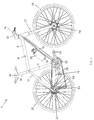
- FIG. 1 schematically illustrates an example of a pedal cycle 2. While Figure 1 shows a bicycle, it will be appreciated that the present technique could also be applied to other types of cycles such as a tricycle, tandem or motorcycle.
- the pedal cycle 2 comprises a frame 4 including a seat tube 6, top tube 8, down tube 10, seat stays 12, and chain stays 14.
- the cycle 2 also includes a saddle 16, seat post 18, handle bars 20, front fork 22, front wheel 24, rear wheel 26, pedals 28, front sprockets or chain rings 30, rear sprockets 32, derailleur 34 and chain 36.
- the cycle 2 is fitted with an electrically assisted cycle kit 50.
- the kit 50 is shown functionally in Figure 2 and shown fitted to the cycle 2 in Figure 1 .
- a standard cycle 2 can be converted into an electrically assisted cycle.
- the cycle kit 50 includes a battery 52 for providing power to the other elements of the cycle kit 50.
- the battery 52 is shown mounted in a cage 54 fitted to the down tube 10 of the frame 4, in a similar way to a cage for a water bottle.
- the battery may be connected to other portions of the frame 4 (for example, the seat tube 6) and need not be formed in the shape of a water bottle.
- the kit 50 is also provided with a battery charger 56 for recharging the battery 52.
- the kit 50 also includes an electric motor 58 for providing electrical assistance for pedal cycle motion.
- the motor 58 is a hub motor fitted to the front wheel 24 of the cycle 2, but in other embodiments a crank drive motor or a rear wheel drive motor can be used.
- a brushless sensorless hub motor is particularly preferred for its reliability, low cost and efficient operation.
- the motor could be a direct drive motor, or a motor with gearing inside a hub (e.g. planetary gearing) to match the speed needed for cycling.
- the cycle kit 50 also includes a controller 60 for controlling the operation of the various components of the cycle kit 50.
- the controller 60 controls the drive of the electric motor 58.
- the controller 60 is provided within the casing of the battery 52, but it will be appreciated that in other embodiments the controller 60 may be located at any location on the cycle 2, such as on the down tube 10 or within the battery cage 54 or motor 58 for example.
- a gear tooth sensor 65 is provided for sensing motion of the teeth and valleys of a gear sprocket 32 of the cycle 2.
- the gear tooth sensor 65 is mounted on the chain stay 14 of the frame 4 to sense the motion of one of the rear sprockets 32.
- the gear tooth sensor 65 may be mounted to a different part of the frame or to the rear axle of the cycle 2, and may sense motion of one of the front chain rings 30 instead of the rear sprockets 32.
- the gear tooth sensor 65 may be fitted to sense the teeth and valleys of the largest rear sprocket 32.
- the gear tooth sensor 65 provides a gear motion signal to the controller 60 and the controller 60 controls the drive of the electric motor 58 based on the gear motion signal.
- the speed/acceleration of motion of the teeth and valleys of the gear sprocket 32 is representative of the speed/acceleration of pedalling by the cyclist, since the sprocket 32 rotates when the pedals rotate. Therefore, by controlling the motor drive based on the sensed speed/acceleration of motion of the gear sprocket 32, the assistance provided by the motor 58 can be controlled in a way that is appropriate to the cyclist's pedalling.
- the gear tooth sensor 65 may be a magnetic sensor which senses the ferrous teeth of the sprocket 32.
- the gear tooth sensor may include a Hall sensor which uses the Hall effect to sense changes in a local magnetic field caused by ferrous objects. Further details of the gear tooth sensor 65 and the control of the motor drive by the controller 60 may be found in the published European patent application EP 2657119 A1 filed by Modern Times Ltd, the entire contents of which are hereby incorporated by reference.
- a user input 76 is also provided to enable the cyclist to control whether or not electrical assistance is provided by the motor 58.
- the user input 76 may be mounted on the handlebar 20 of the cycle 2.
- the user input 76 may for example be an on/off button for switching on and off the power assistance.
- a tactile momentary button may be used which produces different functions by momentary presses or by holding down the button.
- the user input 76 may comprise further controls and/or methods for adjusting parameters or changing mode of the cycle kit 50.
- the cycle kit 50 may optionally also include other elements which are not required for providing electrical assistance but may conveniently be powered using the battery 52.
- the kit 50 may include a cycle computer 80 for providing the cyclist with data such as the cycle speed, distance travelled, and so on.
- front or rear lights 84 may be powered using the battery 52.
- the cycle kit 50 also includes the various wires and connectors for forming electrical connections between the different elements of the system.
- the wires may be run along the frame 4 of the cycle 2 when fitting the kit 50 to the cycle 2, or may be provided internally within the frame 4.
- Figure 2 shows a system in which, to reduce the amount of wiring, the battery 52 is connected to the controller 60 and the power for the other elements of the kit 50 is distributed from the battery 52 via the controller 60, in other embodiments some elements may be connected directly to the battery 52.
- the battery 52 and cage 54 are part of a battery assembly 51 for fitting to a cycle. While in the example of Figures 1 and 2 the battery assembly forms part of an electrically assisted cycle kit 50 for retrofitting to a cycle, in other examples the battery assembly may be provided as part of a standalone electric bike which is designed specifically for electrical assistance, rather than as part of a retrofitting kit. However, the battery assembly which will be discussed below is particularly useful for a kit 50 because of its compact design and simple operation by the user, which means it can be fitted to a wide range of bikes with different sizes and configurations of frames and is convenient to remove or insert the battery from the holder 54.
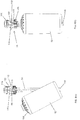
- FIG. 3 schematically shows the battery assembly 51 in more detail.
- the battery assembly 51 includes the battery pack 52, a battery holder (cage) 54, and a connector portion 55 which is slideable relative to the battery holder 54 to clamp the battery pack 52 into the holder 54 and form an electrical connection between the battery of the battery pack 52 and wiring 90 for connecting to various components of the cycle or the cycle kit.
- the wiring 90 may be connected to the motor 58, cycle computer 80, user input button 76, gear tooth sensor 65, and so on.
- the battery assembly may also optionally include a locking member 100 for securing the battery pack 52 to prevent theft.
- the locking member may receive a lock 102 (e.g.
- the locking member 100 will be explained in more detail below.
- FIG. 4 shows the battery holder in more detail.
- the battery holder 54 comprises a cage which has a protruding portion 110 or hook at one end and a neck portion 112 at the other end for receiving the connector portion 55. Between the protruding portion 110 and the neck portion 112 is a bar with multiple fixing holes 114 which allow the battery holder 54 to be mounted at different positions relative to the frame.
- a bicycle frame will typically have some fixings provided on the frame for fitting a water bottle and these can be used to fit the battery assembly 51.
- providing multiple fixing holes 114 in the battery holder 54 allows the battery holder 54 to be moved up and down the frame to ensure that the battery pack 52 fits within the space available, and to take up any slack in the wiring 90 to avoid large loops of wiring or to avoid placing strain on wiring by over-tensioning the wiring.
- the neck portion of the battery holder 54 has engaging portions 118 for engaging with cam portions of the connector portion 55 as will be discussed below.
- the engaging portions 180 are in the form of three lugs which extend inwardly from the loop of the neck portion 112.
- the engaging portions have a hole 120 for receiving a ball which slides between the engaging portion and a groove of the connector portion.
- Figure 5 shows a part of the casing of the battery pack 52.
- the lower part of the casing has an indented portion 130 which has a hemispherical profile. Also within the hemispherical indent is a slot portion 132.
- the protruding portion 110 of the battery holder 54 engages with the indent 130 of the battery pack 52 to centrally position the battery pack 52 relative to the holder 54. Since the indent curves inwards, the user can easily find the indent and the indent will guide the battery pack into the centre of the battery holder. To help with this, the area surrounding the indent may also taper inwards towards the indent, e.g.
- the protruding portion 110 of the battery holder 54 has a curved end profile so that it can slide along the curved surface of the indent 130 of the battery pack 52 to allow the battery pack to be tilted into the battery holder from an angled position to an in use position (see Figure 9 ). Also, when viewed from the side the protruding portion 110 has a flat profile 124 which engages with the slot 132 in the battery pack 52 to align the battery pack in a desired orientation.
- the slot portion 132 of a battery can be aligned such that when the protruding portion is in the slot then the battery will be in one of two orientations possible with respect to the connector portion 55.
- the top cap of the battery pack may have an asymmetric design with for example a makers label 150 on one side of the cap. The user may be instructed that when the battery pack is fitted in the correct orientation, the makers label should point to one side of the frame and not the other, so that the user knows that, when the protruding portion 122 of the battery holder 54 is in the slot 132 of the battery pack 52, then provided that the label 150 on the top of the battery pack is pointing in the right direction then the battery will be correctly aligned.
- the battery pack when inserting the battery, after the protrusion 110 is located in the indent 130, the battery pack merely needs to be twisted a little until the protrusion 110 drops into the slot 132, which provides tactile feedback that it is in position (the slot 132 is indented a little deeper than the hemispherical indent 130).
- FIG 6 shows the connector portion 55 of the battery assembly in more detail.
- the connector portion 55 fits within the loop of the neck portion 112 of the battery holder 54.
- a cap 140 sits over the top of the connector portion and the neck portion 112 of the battery holder to hide the wiring and protect the inside of the connector portion 55 from dust, dirt and water.
- the connector portion 55 includes a guide portion 142 and a rotating part 144 which rotates about the guide portion relative to the battery holder 54.
- the guide portion 142 houses the pins and wires for forming the connection to the battery pack.
- the rotating part 144 includes a finger grip portion 146 which can be gripped by the user to rotate the rotating part relative to the battery holder 54 and the guide portion 142.
- the finger grip portion 146 has an indent 148 in one side for receiving the locking member 100 (see Figure 18 ) so that when the locking member is fitted, the rotating part 144 cannot be rotated to unclamp the battery pack.
- the rotating part 144 includes cam portions 152 disposed around the edge of the rotating part 144, which engage with the engaging portions 118 of the battery holder 54.
- cam portions 152 disposed around the edge of the rotating part 144, which engage with the engaging portions 118 of the battery holder 54.
- fewer or more cam portions and engaging portions may be provided.
- the cam portions 152 could be provided on the battery holder 54 and the engaging portions 118 could be provided on the rotating part 144.
- Figure 7 shows the connector portion 55 in more detail without the battery holder 54
- Figure 8 shows an exploded view of the components of the connector portion 55.
- the guide portion 142 has grooves 160 running down it in an axial direction parallel to the axis of rotation of the rotating part 144.
- a ball 162 which rolls along the groove 160 and in the holes in the engaging part 118 to reduce friction, keep the connector portion central, and provide a nicer feel for the user than a rigid lug in a groove.
- the ball 162 may be made of steel, stainless steel, PTFE or nylon for example.
- the engaging portions 118 of the battery holder 54 follow the grooves 160 in the axial direction, aided by the balls 162.
- the engaging portions 118 slide over the cam portions 152 about the circumference of the rotating part 144, and due to the curved profile of the cam portions 152, the engaging portions 118 force the rotating part 144 down to press against a shoulder of the guide portion which in turn presses down on a mating part (neck) of the battery pack 52 to clamp the battery pack 52 into the battery holder 54.
- the grooves 160 and balls 162 help to retain the connector portion 55 in its original orientation when sliding downwards, so that it slides down linearly to form a secure connection.
- the cam portions 152 have a profile such that, once the engaging parts are over the highest point of the cam portion 152, then the cam portion 152 surface curves down again so that the engaging part 118 rests on the far side of the cam portion. This ensures that the connector portion remains in the closed position until the user rotates the rotating part 144 back round to unclamp the battery pack.
- the connector portion also includes a wiring guide 170 which clips onto the top of the guide portion 142 for guiding wiring away from the connector portion and down to the frame of the cycle.
- the wiring is clamped by plastic gripper portions 182 of the wiring guide 170 to prevent stressing of the wires and contacts and rattling of the wiring, and to guide the wiring down in an arc to the frame as shown in Figure 3 .
- the clamping action is performed with a bolt and nut through the hole 183 which both secures the connector assembly together, clamps the wires passing through the gripper portions 182 and provides a fixture for the cap 140.
- Figure 8 also shows a connector socket 190 which lies within the top of the battery pack 152.
- the guide portion 142 descends down over the connector socket 190 at the top of the battery pack 52.
- the wiring may be guided by the wiring guide 170 into the guide portion 142 and may terminate with a number of connector pins which are inserted into corresponding holes in the connector socket 190 when the connector portion 55 is slid downwards by rotating the rotating part 144.
- An O-ring (not illustrated in the drawings) may be provided which sits in a groove below the shoulder 192 of the guide portion 142, above orientation ribs 194 in the lower part of the guide portion. The O-ring seals the connector when mated to prevent water or dirt entering the battery pack.
- a number of orientation ribs 194 are provided with an asymmetric arrangement (e.g. five ribs spaced around the edge of the guide portion), which engage with corresponding slots 196 in the top of the battery (see Figure 12 ), to provide further protection against inserting the battery the wrong way round.
- the battery charger 56 may similarly have a set of orientation ribs 194 which engage with the slots 196 in the top of the battery, to prevent incorrect connection of the battery to the charger.
- FIGs 9(A) to 9(C) schematically illustrates how the battery pack 52 can be inserted into the holder 54 and the battery pack is clamped and the connection formed using the connector portion 55.
- the battery pack 52 is inserted into the battery holder 54 at an angle, with the curved indent at the base of the battery pack 52 engaging with the protruding portion 110 of the battery holder 54 so that the battery is aligned centrally relative to the holder.
- the hemispherical indent allows easy location in centre of base of battery, and the conical section surrounding the indent allows easy location of the indent.
- the user also twists the battery pack to locate the flat profile of the protruding portion 110 in the slot 132 in the bottom of the battery casing, with the label part 150 pointing outwards in a certain direction to ensure that the battery pack 52 is aligned correctly with the connector portion 55.
- the user will feel the protruding portion 110 drop into the slot 132 when the battery is correctly aligned.
- the user then tilts the battery pack into the in-use position.
- the connector portion 55 is in an open position where it lies above the battery pack, and the engaging portions 118 of the battery holder 54 lie at the foot of the corresponding cam portions 152, so that the connector portion provides clearance for the battery pack 52 to be tilted into position.
- the battery assembly is much more compact since there is no need to provide additional space above the battery for inserting the battery. This means that the battery pack can be fitted to smaller bike frames.
- the user then grips the grip portion 146 of the connector portion 55, slides the connector portion 55 down towards the battery, and rotates the rotating part 144 relative to the battery holder 54 and guide portion 118 (as shown in Figure 11 , some examples may not require sliding the connector portion 55 down before rotating).
- the engaging portions 118 travel in the direction of the grooves 160 of the guide portion 142 to keep the connector portion 55 in the correct orientation so that the connector portion 55 slides in a linear direction towards the battery.
- the engaging portions 118 of the holder 54 slide along the cam portions 152 to press the connector portion 55 downwards and clamp the battery pack 52 against the protruding portion 110 at the base of the battery holder 54. This secures the battery pack 52 to prevent it falling out or rattling while the cycle is in motion.
- this design of the connector portion 55 and battery holder 54 provides a compact battery assembly which can fit to a range of sizes of cycle frames, and which is very simple to operate for the user, and can securely clamp the battery in position at the same time as making the electrical connections. This is not possible with existing battery assemblies for cycles. A single twist by the user is enough to both complete the electrical connection with the battery and clamp the battery into the holder.
- Figures 10 and 11 show two examples of the rotating part 144 of the connector portion 55.
- Figure 10 shows the same rotating part 144 used in Figures 6-9 , where the cam portion 152 has a profile such that initially the cam portion rises vertically away from the grip part 146 of the rotating part 144, and then curves away to the side to allow the engaging part 118 to slide over it as the user rotates the rotating part.
- the cam portion 152 starts curving away to the side from the foot of the well, so that rotation of the rotating part 144 causes the engaging portion 118 to slide up the cam portion 152 without any need to first slide the connector portion 55 downwards before rotating the rotating part 144.
- FIG 12 shows the top cap 200 of the battery pack 52 in more detail.
- the top cap includes a label portion 150 which may be used to ensure the correct orientation of the battery.
- the label portion 150 may include one or more LEDs (light emitting diode) 202 for signalling information to the user, such as whether the amount of remaining charge in the battery is low. For example, a cluster of LEDs of different colours may be provided. In other examples, the LEDs 202 may be located on a different part of the battery pack 52.
- the top cap also includes a locking recess 204 for receiving a protruding part of the locking member 100 (see Figures 18 and 19 discussed below).
- Figure 13 shows a side view of the top cap 200, which shows that the locking recess 204 has barrier portions 206 which trap the protruding part of the locking member 100 in the recess so that it cannot slide out sideways unless the protruding part of the locking member is pushed downwards, which cannot occur unless the locking member is unlocked.
- the top cap 200 of the battery pack is die cast from aluminium or another metal or alloy, so that it acts as a heat sink portion for dissipating heat from within the battery casing.
- the cap 200 has a number of heat radiating fins 208 which extend outwards from the centre of the cap 200, providing increased surface area to improve heat dissipation. Forming the top cap as a heat sink is useful to prevent overheating of a control unit (which may comprise a motor drive) 60 (e.g. microcontroller on a printed circuit board) located inside the casing of the battery pack 52.
- a number of bolts 210 may be provided within the battery pack to hold the battery pack together. As shown in Figure 5 , the foot of each bolt may lock to the bottom of the casing.
- Each bolt then passes through the entire length of the battery pack 52, including through the printed circuit board forming the control unit 60, and then couples to the metal heat sink at the top cap 200 of the battery pack 52.
- the bolts By connecting the bolts to the heat sink, the bolts help to conduct heat through the battery pack into the heat sink to improve heat dissipation.
- a threaded bar may pass through the battery pack, and each part may be bolted on to the bar with nuts.
- Some "studding" may be screwed into the cap through the PCB 60, and then a spacer and a nut behind the studding may secure the PCB 60 in the cap, and the bar then goes through the battery pack and is secured with another washer and nut on the other side of the battery pack. Finally, the bottle bottom goes on and is secured with the final nuts on the bottom of the bottle.
- the control unit 60 may detect how much charge is remaining in the battery, e.g. by detecting whether the battery voltage drops below a threshold or by coulomb counting. If the voltage is lower than a certain amount, then the control unit 60 may control the LEDs 202 to be illuminated in a certain colour to inform the user how much charge is remaining. For example, a red LED may be illuminated if the amount of charge is low, and a green LED be illuminated otherwise, or another scheme may be used to indicate the amount of charge.
- the control unit 60 may be triggered to display the amount of remaining charge by the user shaking the battery pack 52 back and forth.
- the control unit 60 may detect a signature pattern of motion (e.g. a set sequence) and detect the remaining charge when the pattern is detected.
- control unit 60 may control an amount of current supplied to the motor based on the detected battery voltage. For example, there may a minimum safe voltage at which the battery can operate to prevent damage. If the voltage drops below this threshold, then the battery will shut off and no assistance may be provided. However, sometimes when activating the electrical assistance from the motor, the level of current drawn from the battery can cause the voltage to drop below the battery protection threshold even though there is still plenty of usable energy stored in the battery. Usually the higher the current drawn, the more the battery voltage drops. Since the battery voltage will also gradually reduce as the battery charge level reduces, when the remaining battery charge gets to a certain point the higher current levels used for assistance can cause a voltage drop that exceeds the threshold.
- the control unit 60 may gradually taper down the maximum current drawn from the battery as the battery charge decreases.
- the control unit 60 may set a tapering voltage threshold which is higher than the minimum safe voltage, and when the battery voltage reaches this threshold, the control unit 60 may reduce a maximum current that can be drawn from the battery. With less current being drawn, the voltage will then rise again, and when it reaches the tapering threshold once more than the current can be reduced further.
- some operating parameters of the control unit 60 may be adjusted by the user, by connecting the battery pack to an external device such as a personal computer. For example, the current or current limit provided in each of a number of user modes may be selected by the user.
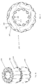
- FIG 14 inside the casing may be arranged a number of layers 220 of battery cells 222.
- Figure 14 shows two layers of cells, but it will be appreciated that other examples may include a single layer or three or more layers 220.
- Each layer 220 comprises a number of cells 222 held between two cell holders 230 which grip the ends of the battery cells 222. While Figure 14 shows two cell holders 230 being placed back to back between adjacent layers 220, in other examples a single cell holder 230 could grip both the bottom end of one layer of cells and the top end of the other layer of cells.
- the battery cells 222 may for example be lithium cells or nickel metal hydride cells.
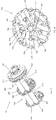
- Figure 15 shows an example of the cell holder 230 in more detail.
- the cell holder 230 which may be moulded from plastic, includes a number of protrusions 240 which are positioned in the gaps between adjacent cells 222, and which have wing portions 242 extending from the protrusions 244 for gripping the side of cells.
- the wing portions 242 are formed by a moulding tool which extends up during manufacturing to form the cell portion through holes 244 located below each wing portion to allow for the passage of the moulding tool. Without these holes 244, the wing portions would still be connected to the base of the cell holder and so could not flex.
- the wing portions 242 of protrusions 240 at the edge of the cell holder do not require moulding holes 244 because the moulding tool can reach these wing portions 242 because the base does not extend to the edge of the cell holder 230 below the outer wing portions 242.
- Slot-shaped holes 246 are also formed in the base of the cell holder 230 for receiving electrical contacts, such as rectangular strips of nickel. The cells are placed in the approximately circular gaps between the wing portions of neighbouring protrusions 240.
- the cells 222 can be packed closer together since there is no need to provide a solid layer of plastic around each cell, which would take up additional space. This allows the sides of adjacent cells 222 to be placed closer to each other and allows a circular battery pack to be produced where the cell holder 230 does not add anything to the overall diameter of the finished battery pack, which makes the overall battery pack much more compact. Also the arrangement of wing portions 242 extending from protrusions 244 allows much greater flexibility in the cell sizes the cell holders 230 are able to accommodate, thereby meaning one cell holder 230 is suitable for a wider range of cell diameters than is the case with existing types of cell holder.
- the cell holder 230 holds 15 cells: an inner ring of 5 cells and an outer ring of 10 cells.
- the example of Figures 14 and 15 can be used for all types of cylindrical cells but it is particularly beneficial for cells that do not require a minimum gap between adjacent cells, such as nickel metal hydride cells, but could also be used for other cell types with a similar shape. Whilst for example cylindrical lithium ion cells require a gap between adjacent cells of typically 1 mm, the arrangement in Figures 14 and 15 avoids the extra spacing which results from the plastic thickness of traditional cell holders and allows for a smaller battery case because the cell holder 230 does not add to the overall diameter of the pack. This also means that a closer contact between the cells and the outer case can be achieved which can be beneficial for heat transfer.
- Figures 16 and 17 show another example of cell holders designed for holding 10 lithium ion cells 222 which allows the same diameter of pack as the 15 cell example in Figures 14 and 15 whilst incorporating a gap between cells of approximately 1mm when using standard 18mm diameter cells.
- a ring of 10 cells is held around the outside of the cell holder 230, with a space in the middle.
- the cell holder 230 has protrusions 240 with wing portions 242 for gripping parts of the edges of the cells.
- the moulding holes 244 there is no need for the moulding holes 244 because the wing portions 242 are all near the edge of the cell holder 230 or next to the central hole, so there is space for moulding tool to mould the wing portions.
- Figures 18 and 19 show the locking member 100 in more detail (the padlock 102 has been omitted from Figure 18 to provide a better view of the locking member 100, but in use would be inserted into the hole of the locking member to secure the locking member).
- the locking member 100 nestles against the indent 148 in the rotating part of the connector portion 55 (the indent 148 is shown in Figure 6 ) so that when the locking member is fitted then the rotating part cannot be rotated and so the connector portion cannot be removed from the battery pack. Hence the battery pack will remain clamped into the holder.
- a protruding part of the locking member 100 fits into the locking recess 204 of the battery pack to secure the locking member to the battery pack. Due to the barrier portions 206 in the locking recess, the locking member 100 cannot be slid out sideways.
- Figure 19 shows the locking member 100 both when assembled (part (a) of Figure 19 ) and in an exploded view (part (b)).
- the locking member 100 includes a first portion (or outer sleeve) 300 and a second portion (or inner sliding rod 302) which are moveable relative to each other and each include a hole 304 for receiving the lock 102.
- a pin 306 passing through a slot 307 in the second portion 302 of the locking member and fits into holes 308 in the outside of the outer sleeve 300 to fix the two portions 300, 302 together.
- a spring 310 is provided between the second portion 302 and the pin 306.
- the lower portion of the second portion 302 comprises a protruding part 312 with a shaped head 314 which engages with the locking recess 204 so that the head cannot be shifted out sideways from the locking recess 204 once the locking member is locked.
- the spring biases the inner portion 302 upwards relative to the pin 306 connected to the outer sleeve 300, so that the head 314 of the protruding portion 312 is drawn upwards so that it will remain behind the barrier parts 206 of the locking recess 204 to prevent lateral movement.
- the user can only remove the locking member from the battery pack by pushing down the inner portion 302 relative to the outer sleeve to disengage the head 314 of the protruding portion 312 from the locking recess and then slide the locking member outwards.
- the pin 306 moves up in the slot, compressing the spring 310.
- the user presses and holds the button at the top of the locking member 100, slides the locking member 100 into the recess 204 until it clicks when the protrusion 312 is pushed up into the recess, and then locks with a lock 102 (e.g. padlock which can be locked around a cable or D lock).
- a lock 102 e.g. padlock which can be locked around a cable or D lock.
- the round locking member 100 sits in a vertical groove 148 in the knurled rotating part of the connector so it cannot be turned without removing the lock.
- Figures 20 to 22 show another example of a locking member 100 and corresponding end cap for the battery pack.
- the end cap of the battery pack 52 may be provided with a circular hole 330 with a lip 332 and an undercut below the lip 332.
- Figure 21 shows an exploded view of the locking member 100, which comprises an outer portion 340 and inner portion 341, and a spring 342 for biasing the inner portion upwards relative to the outer portion 340 .
- the outer and inner portions 340, 341 each have a hole 343 for receiving a padlock or cable.
- the outer portion 340 has a protruding portion 344 which is narrower than the rest of the outer portion 340 and fits into the circular hole 330 in the battery pack 52.
- the inner portion 341 of the locking member 100 has a waist portion 345 which narrows and then gets wider again towards the foot 348 of the inner portion 341.
- Four balls 346 sit between the waist portion 345 of the inner portion 341 and circular windows 347 in the outer portion 340.
- the user pushes down the top of the inner portion 341 to bring the holes 343 in the inner and outer portions out of alignment.
- the windows 347 holding the balls 346 align with the narrowest part of the waist portion 345 of the inner portion 341, so that when the locking member 100 is inserted into the circular hole 330 in the battery pack 52, the balls 346 can drop into the waist portion 345 so that they can pass the lip 332 of the circular hole 330.
- the user then releases the top of the inner portion 341 so that the spring 342 biases the inner portion 341 upwards relative to the outer portion 340.
- the windows 347 in the outer portion 340 line up with the foot 348 of the inner portion 341 which is wider than the waist portion 345, so that the balls 346 are pushed out of the windows 347 into the undercut portion of the hole 330 in the battery pack.
- the holes 343 in the outer and inner portions 340, 341 are now aligned with each other, as shown in Figure 22 .
- the user can now pass a padlock or cable through the holes 343 to secure the locking member 100. Once the padlock or cable has been inserted, the holes 343 can no longer be brought out of alignment, and the locking member 100 cannot be removed from the battery pack 52 because the balls 346 cannot pass the lip 332 of the hole 330 in the battery pack. While this example shows four balls 346 being provided, it will be appreciated that other examples may have more or fewer balls.
- Figure 23 shows a secondary cable guide 350 which may optionally be provided, for routing the cables on either side of a tube or portion of the frame of the cycle, and preventing rattling of the battery holder 54.
- the secondary cable guide 350 holds the wires against the cycle frame and maintains a desirable arc in the wiring as the connector portion moves to prevent damage to the wiring.
- the cable guide 350 may be made from a flexible plastic which can flex to accommodate different bicycle frame widths in this position on the bicycle. In some cycles, the fixings for attaching water bottles or other objects protrude out a little (e.g.
- the secondary cable guide may run under the battery holder 54 to fill the gap between the frame and the battery holder 54.
- the cable guide 350 has flexible arms 351 which can be pushed apart when fitting the cable guide 350 to the frame of the cycle, and then spring back together again to grip the frame.
- the battery holder 54 clips into part 352 of the cable guide 350 and is held by gripping portions 354, and a protrusion 356 on the cable guide 350 engages with one of the fixing holes 114 of the battery holder 54.
- Cable grips 358 hold the wiring in position. In some examples, the wiring may already be held by the cable grips 358 when the cable guide 350 is fitted to the frame. In one example, three cables may extend from the connector portion, for connecting to the motor 58, user input 76 and gear tooth sensor 65.
- the motor cable 360 is held in the outer part of the double cable grip 358-1, and the pedal sensor cable 362 runs in exactly the same curve as the motor cable to the connector behind it (through the inner part of grip 358-1), then loops back on itself and through cable grip 358-2 and back down along the side of the cage 54.
- Figure 25 shows the cable routing on the other side of the frame to Figure 24 , with the user input cable 364 running through cable grip 358-3 on the other side of the frame. This provides a neat arrangement for the wiring and does not require the person fitting to the cycle to understand how these cables should be routed. However, it will be appreciated that other examples may run the cables in a different manner.
Landscapes
- Engineering & Computer Science (AREA)
- Chemical & Material Sciences (AREA)
- General Chemical & Material Sciences (AREA)
- Chemical Kinetics & Catalysis (AREA)
- Electrochemistry (AREA)
- Mechanical Engineering (AREA)
- Manufacturing & Machinery (AREA)
- Combustion & Propulsion (AREA)
- Transportation (AREA)
- Microelectronics & Electronic Packaging (AREA)
- Sustainable Development (AREA)
- Life Sciences & Earth Sciences (AREA)
- Sustainable Energy (AREA)
- Power Engineering (AREA)
- Automation & Control Theory (AREA)
- General Physics & Mathematics (AREA)
- Physics & Mathematics (AREA)
- General Engineering & Computer Science (AREA)
- Battery Mounting, Suspending (AREA)
Claims (15)
- Ensemble batterie (51) pour monter après coup un bloc-batterie sur un cadre d'une bicyclette, l'ensemble batterie comprenant :un support de batterie (54) pour être monté après coup sur le cadre, dans lequel le support de batterie est configuré pour supporter le bloc-batterie ;une partie de connecteur (55) configurée pour former un raccordement électrique entre un câblage pour raccorder au moins un composant de la bicyclette et le bloc-batterie lorsque le bloc-batterie est supporté par le support de batterie, dans lequel la partie de connecteur peut être glissée à l'intérieur d'une partie du support de batterie dans une direction linéaire par rapport au support de batterie entre une position ouverte assurant un jeu pour le bloc-batterie à insérer dans le support de batterie ou à retirer de ce dernier, et une position fermée dans laquelle la partie de connecteur vient en prise avec une partie homologue du bloc-batterie pour former le raccordement électrique avec le bloc-batterie ; etun mécanisme de serrage (118, 152) configuré pour fixer le bloc-batterie contre le support de batterie lorsque la partie de connecteur est en position fermée.
- Ensemble batterie selon la revendication 1, dans lequel le support de batterie comprend une partie de mise en prise (122) pour venir en prise avec une partie correspondante (132) du bloc-batterie lorsque le bloc-batterie est inséré dans le support de batterie dans une position inclinée qui est inclinée par rapport à une position d'utilisation du bloc-batterie ; et
la partie de mise en prise est configurée pour permettre au bloc-batterie d'être incliné depuis la position inclinée dans la position d'utilisation pendant que la partie correspondante du bloc-batterie est mise en prise avec la partie de mise en prise du support de batterie. - Ensemble batterie selon la revendication 2, dans lequel la partie de mise en prise comprend une partie en saillie du support de batterie pour venir en prise avec une partie échancrée du bloc-batterie.
- Ensemble batterie selon la revendication 3, dans lequel la partie en saillie comprend une surface d'extrémité incurvée pour coulisser contre une surface d'échancrure incurvée de la partie échancrée du bloc-batterie lorsque le bloc-batterie est incliné entre la position inclinée et la position d'utilisation.
- Ensemble batterie selon l'une quelconque des revendications précédentes, dans lequel la partie de connecteur comprend au moins une partie du mécanisme de serrage et la partie de connecteur est configurée à la fois pour achever le raccordement électrique et pour fixer le bloc-batterie dans le support de batterie en réponse à une simple opération d'utilisateur.
- Ensemble batterie selon l'une quelconque des revendications précédentes, dans lequel la partie de connecteur comprend une partie rotative (144) qui peut tourner par rapport au support de batterie ; et
le mécanisme de serrage comprend au moins une partie de came (152) disposée sur l'un de la partie rotative et du support de batterie, et au moins une partie de mise en prise (118) disposée sur l'autre de la partie rotative et du support de batterie ; et
dans lequel la ou les parties de came et la ou les parties de mise en prise sont configurées de telle sorte que la rotation de la partie rotative par rapport au support de batterie contraigne la ou les parties de mise en prise à coulisser par rapport à la ou aux parties de came pour forcer une partie de la partie de connecteur vers le bloc-batterie pour fixer le bloc-batterie dans le support de batterie. - Ensemble batterie selon la revendication 6, dans lequel le mécanisme de serrage comprend au moins trois parties de came et au moins trois parties de mise en prise.
- Ensemble batterie selon l'une quelconque des revendications 6 et 7, dans lequel la partie de connecteur comprend une partie de guidage (142) ;
la partie rotative peut tourner par rapport à la partie de guidage autour d'un axe de rotation ;
la partie de guidage comprend au moins une rainure (160) alignée dans une direction axiale parallèle audit axe de rotation ; et
à la suite de la rotation de la partie rotative, la ou les parties de mise en prise sont configurées pour coulisser par rapport à la ou aux parties de came dans une direction de rotation et également pour suivre la ou les rainures dans la direction axiale pour forcer une partie de la partie de connecteur vers le bloc-batterie dans la direction axiale pour fixer le bloc-batterie dans le support de batterie. - Ensemble batterie selon l'une quelconque des revendications précédentes, comprenant en outre le bloc-batterie ;
dans lequel le bloc-batterie comprend une partie échancrée (130) pour recevoir une partie en saillie du support de batterie et la partie échancrée du bloc-batterie comprend une surface d'échancrure incurvée pour coulisser contre une surface d'extrémité incurvée de la partie en saillie du support de batterie. - Ensemble batterie selon la revendication 9, dans lequel la partie échancrée comprend une échancrure sensiblement hémisphérique.
- Ensemble batterie selon l'une quelconque des revendications 9 et 10, dans lequel la partie échancrée du bloc-batterie comprend une partie de fente (132) configurée pour recevoir la partie en saillie du support de batterie pour aligner le bloc-batterie par rapport à la partie en saillie.
- Ensemble batterie selon l'une quelconque des revendications précédentes, comprenant en outre le bloc-batterie (52), dans lequel une unité de commande (60), configurée pour commander le ou les composants est située à l'intérieur d'un boîtier du bloc-batterie ;
l'unité de commande est configurée pour détecter un mouvement prédéterminé du bloc-batterie ; et
à la suite du fait que l'unité de commande détecte le mouvement prédéterminé, l'unité de commande est configurée pour fournir une indication d'une quantité de charge restante dans la batterie du bloc-batterie. - Ensemble batterie selon l'une quelconque des revendications précédentes, comprenant en outre le bloc-batterie, dans lequel une unité de commande configurée pour commander le ou les composants est située à l'intérieur d'un boîtier du bloc-batterie ;
le ou les composants comprennent un moteur électrique et l'unité de commande est configurée pour commander l'entraînement du moteur électrique en régulant une quantité de courant fournie au moteur électrique ; et
l'unité de commande est configurée pour réduire une quantité maximale de courant fournie au moteur électrique chaque fois que la batterie passe un point de fonctionnement de seuil d'une pluralité de points de fonctionnement de seuil correspondant à différentes quantités de charge restantes dans la batterie. - Ensemble batterie selon l'une quelconque des revendications précédentes, comprenant en outre le bloc-batterie, dans lequel le bloc-batterie comprend, disposés à l'intérieur d'un boîtier du bloc-batterie, une pluralité de cellules de batterie et au moins un support de cellule configuré pour supporter des extrémités d'au moins quelques-unes des cellules de batterie ; et
le ou les supports de cellule comprennent une pluralité de saillies à des positions correspondant à des espaces entre les cellules de batterie, chaque saillie ayant au moins une partie d'aile s'étendant depuis la saillie pour saisir une partie d'une cellule de batterie correspondante. - Kit de bicyclette à assistance électrique pour être monté après coup sur une bicyclette, le kit comprenant l'ensemble batterie selon l'une quelconque des revendications précédentes.
Priority Applications (3)
| Application Number | Priority Date | Filing Date | Title |
|---|---|---|---|
| EP14181821.1A EP2988345B1 (fr) | 2014-08-21 | 2014-08-21 | Ensemble de batteries permettant de monter un bloc-batterie à un cadre de bicyclette |
| US14/824,266 US9385357B2 (en) | 2014-08-21 | 2015-08-12 | Battery assembly for fitting a battery pack to a frame of a cycle |
| CA2900281A CA2900281A1 (fr) | 2014-08-21 | 2015-08-13 | Dispositif a piles servant a raccorder un bloc-pile a un cadre d'une bicyclette |
Applications Claiming Priority (1)
| Application Number | Priority Date | Filing Date | Title |
|---|---|---|---|
| EP14181821.1A EP2988345B1 (fr) | 2014-08-21 | 2014-08-21 | Ensemble de batteries permettant de monter un bloc-batterie à un cadre de bicyclette |
Publications (2)
| Publication Number | Publication Date |
|---|---|
| EP2988345A1 EP2988345A1 (fr) | 2016-02-24 |
| EP2988345B1 true EP2988345B1 (fr) | 2018-12-26 |
Family
ID=51421828
Family Applications (1)
| Application Number | Title | Priority Date | Filing Date |
|---|---|---|---|
| EP14181821.1A Active EP2988345B1 (fr) | 2014-08-21 | 2014-08-21 | Ensemble de batteries permettant de monter un bloc-batterie à un cadre de bicyclette |
Country Status (3)
| Country | Link |
|---|---|
| US (1) | US9385357B2 (fr) |
| EP (1) | EP2988345B1 (fr) |
| CA (1) | CA2900281A1 (fr) |
Cited By (1)
| Publication number | Priority date | Publication date | Assignee | Title |
|---|---|---|---|---|
| WO2022200939A1 (fr) * | 2021-03-22 | 2022-09-29 | Sachin Anant Jadhav | Véhicule électrique à deux roues pouvant être enregistré en rto à l'aide d'une pédale |
Families Citing this family (23)
| Publication number | Priority date | Publication date | Assignee | Title |
|---|---|---|---|---|
| US9394030B2 (en) * | 2012-09-27 | 2016-07-19 | Sram, Llc | Rear derailleur |
| US9914501B2 (en) * | 2014-03-18 | 2018-03-13 | Askoll Eva S.R.L. | Battery holder device for electric bicycle |
| CN105667693B (zh) | 2014-12-05 | 2018-08-10 | 株式会社岛野 | 自行车用控制装置 |
| US10447017B2 (en) * | 2016-04-14 | 2019-10-15 | Autonetworks Technologies, Ltd. | Electric storage device |
| CN106627968A (zh) * | 2016-12-14 | 2017-05-10 | 肇庆理士电源技术有限公司 | 自行车用锂电瓶 |
| JP6688726B2 (ja) * | 2016-12-26 | 2020-04-28 | 株式会社シマノ | 自転車用制御装置および自転車用制御システム |
| CN207360490U (zh) * | 2016-12-31 | 2018-05-15 | 浙江泓源汽车集团有限公司 | 立式折叠电动自行车 |
| WO2018237353A1 (fr) * | 2017-06-23 | 2018-12-27 | Social Bicycles Inc. | Bicyclette à assistance électrique |
| GB2566693B (en) | 2017-09-20 | 2022-08-17 | Swytch Tech Ltd | A power unit and electric drive system for a bike |
| CN107834679B (zh) * | 2017-10-17 | 2024-04-26 | 华南理工大学 | 一种共享单车的多功能供电系统 |
| JP6878321B2 (ja) * | 2018-01-16 | 2021-05-26 | 株式会社オートネットワーク技術研究所 | 配線モジュールおよび蓄電モジュール |
| US11046389B2 (en) | 2018-08-21 | 2021-06-29 | Specialized Bicycle Components, Inc. | Ebike battery mount |
| US11124259B2 (en) * | 2018-08-21 | 2021-09-21 | Specialized Bicycle Components, Inc. | Bicycle with housing loop stay |
| CN208862729U (zh) * | 2018-09-21 | 2019-05-14 | 睿思特国际有限公司 | 一种用于移动冰箱的防水外置电源 |
| CN109786598B (zh) * | 2018-12-27 | 2021-12-14 | 中国电子科技集团公司第十八研究所 | 一种中孔热电池单体电池装配结构 |
| GB2572466B (en) * | 2019-01-03 | 2020-05-20 | Aubrey Searles Mark | Battery holder |
| CN110008547B (zh) * | 2019-03-25 | 2022-11-29 | 山东省科学院海洋仪器仪表研究所 | 一种水下数据采集舱直流电源模块的传热分析方法 |
| DE102019213435A1 (de) * | 2019-09-04 | 2021-03-04 | Robert Bosch Gmbh | Halter für einen Energieträger/ Energiespeicher (Akku) integriert in einen Fahrradrahmen |
| CN211139558U (zh) * | 2019-11-18 | 2020-07-31 | 深圳飞道科技发展有限公司 | 一种电动自行车的内置电池装置 |
| CN113028270B (zh) * | 2021-03-16 | 2022-10-11 | 永安行科技股份有限公司 | 一种带有身份识别的储氢器及氢燃料电动自行车 |
| CN112623087A (zh) * | 2020-11-10 | 2021-04-09 | 浙江春风动力股份有限公司 | 一种电动摩托车 |
| US20240055709A1 (en) * | 2021-02-25 | 2024-02-15 | Honda Motor Co., Ltd. | Battery pack |
| CN114516381B (zh) * | 2022-01-21 | 2024-01-02 | 江苏苏美达五金工具有限公司 | 一种便于装卸的电池座舱及电动自行车 |
Family Cites Families (8)
| Publication number | Priority date | Publication date | Assignee | Title |
|---|---|---|---|---|
| JP3403874B2 (ja) * | 1994-12-07 | 2003-05-06 | 本田技研工業株式会社 | 電動2輪車のバッテリケース取付構造 |
| JP3622021B2 (ja) * | 1996-07-31 | 2005-02-23 | ヤマハ発動機株式会社 | 脱着式バッテリボックスのロック機構 |
| JP4277968B2 (ja) * | 1999-05-25 | 2009-06-10 | 本田技研工業株式会社 | 電動補助自転車のバッテリ取付構造 |
| US8162191B2 (en) * | 2008-04-21 | 2012-04-24 | Shimano Inc. | Bicycle battery holder |
| US8413947B2 (en) * | 2010-11-12 | 2013-04-09 | Joy Industrial Co., Ltd. | Positioning device for battery box |
| US9399499B2 (en) * | 2011-06-29 | 2016-07-26 | Shimano Inc. | Bicycle battery holder |
| WO2013044242A2 (fr) * | 2011-09-22 | 2013-03-28 | Faraday Bicycles, Inc. | Bicyclette électrique |
| GB2501496B (en) | 2012-04-24 | 2015-06-03 | Modern Times Ltd | Electrically assisted cycle kit |
-
2014
- 2014-08-21 EP EP14181821.1A patent/EP2988345B1/fr active Active
-
2015
- 2015-08-12 US US14/824,266 patent/US9385357B2/en active Active
- 2015-08-13 CA CA2900281A patent/CA2900281A1/fr not_active Abandoned
Non-Patent Citations (1)
| Title |
|---|
| None * |
Cited By (1)
| Publication number | Priority date | Publication date | Assignee | Title |
|---|---|---|---|---|
| WO2022200939A1 (fr) * | 2021-03-22 | 2022-09-29 | Sachin Anant Jadhav | Véhicule électrique à deux roues pouvant être enregistré en rto à l'aide d'une pédale |
Also Published As
| Publication number | Publication date |
|---|---|
| US9385357B2 (en) | 2016-07-05 |
| US20160056432A1 (en) | 2016-02-25 |
| EP2988345A1 (fr) | 2016-02-24 |
| CA2900281A1 (fr) | 2016-02-21 |
Similar Documents
| Publication | Publication Date | Title |
|---|---|---|
| EP2988345B1 (fr) | Ensemble de batteries permettant de monter un bloc-batterie à un cadre de bicyclette | |
| EP3677492B1 (fr) | Support de batterie | |
| US6158881A (en) | Seat post | |
| EP2738080B1 (fr) | Structure d'organisation des composants électriques pour une automobile électrique | |
| EP2423096A2 (fr) | Bicyclette | |
| US9738347B2 (en) | Bicycle with battery mount | |
| US8727367B2 (en) | Bicycle with integrated cable routing | |
| DK2657119T3 (en) | Electric assisted equipment for a bicycle | |
| US7147238B2 (en) | Bicycle part with a partitioned chamber | |
| EP2532573B1 (fr) | Dispositif embarqué sur bicyclette et dispositif de montage et support correspondant | |
| US9085342B2 (en) | Power assisted vehicle | |
| US20130257374A1 (en) | Charging device for electrically driven vehicle, and vehicle incorporating the same | |
| EP2452866A1 (fr) | Ensemble de détection de câble de dérailleur pour bicyclette auxiliaire électrique | |
| WO2017009637A1 (fr) | Cycle électrique | |
| JP5572722B2 (ja) | 電動自転車に対する電源配置 | |
| KR100989374B1 (ko) | 자전거용 우산 장착기 | |
| US20230029793A1 (en) | System for charging electrical micromobility vehicles | |
| JP2003182668A (ja) | 電動補助自転車 | |
| WO2019155482A1 (fr) | Système de verrouillage pour bloc-batterie dans des véhicules électriques | |
| US20240158042A1 (en) | Bicycle with battery, motor and motor mount, wire routing, speed sensor, and dropper seat post | |
| CN203228876U (zh) | 带感光系统的电动自行车 |
Legal Events
| Date | Code | Title | Description |
|---|---|---|---|
| PUAI | Public reference made under article 153(3) epc to a published international application that has entered the european phase |
Free format text: ORIGINAL CODE: 0009012 |
|
| AK | Designated contracting states |
Kind code of ref document: A1 Designated state(s): AL AT BE BG CH CY CZ DE DK EE ES FI FR GB GR HR HU IE IS IT LI LT LU LV MC MK MT NL NO PL PT RO RS SE SI SK SM TR |
|
| AX | Request for extension of the european patent |
Extension state: BA ME |
|
| 17P | Request for examination filed |
Effective date: 20160823 |
|
| RBV | Designated contracting states (corrected) |
Designated state(s): AL AT BE BG CH CY CZ DE DK EE ES FI FR GB GR HR HU IE IS IT LI LT LU LV MC MK MT NL NO PL PT RO RS SE SI SK SM TR |
|
| GRAP | Despatch of communication of intention to grant a patent |
Free format text: ORIGINAL CODE: EPIDOSNIGR1 |
|
| STAA | Information on the status of an ep patent application or granted ep patent |
Free format text: STATUS: GRANT OF PATENT IS INTENDED |
|
| INTG | Intention to grant announced |
Effective date: 20180720 |
|
| GRAS | Grant fee paid |
Free format text: ORIGINAL CODE: EPIDOSNIGR3 |
|
| GRAA | (expected) grant |
Free format text: ORIGINAL CODE: 0009210 |
|
| STAA | Information on the status of an ep patent application or granted ep patent |
Free format text: STATUS: THE PATENT HAS BEEN GRANTED |
|
| AK | Designated contracting states |
Kind code of ref document: B1 Designated state(s): AL AT BE BG CH CY CZ DE DK EE ES FI FR GB GR HR HU IE IS IT LI LT LU LV MC MK MT NL NO PL PT RO RS SE SI SK SM TR |
|
| REG | Reference to a national code |
Ref country code: GB Ref legal event code: FG4D |
|
| REG | Reference to a national code |
Ref country code: CH Ref legal event code: EP |
|
| REG | Reference to a national code |
Ref country code: AT Ref legal event code: REF Ref document number: 1082656 Country of ref document: AT Kind code of ref document: T Effective date: 20190115 |
|
| REG | Reference to a national code |
Ref country code: DE Ref legal event code: R096 Ref document number: 602014038507 Country of ref document: DE |
|
| REG | Reference to a national code |
Ref country code: IE Ref legal event code: FG4D |
|
| REG | Reference to a national code |
Ref country code: NL Ref legal event code: FP |
|
| PG25 | Lapsed in a contracting state [announced via postgrant information from national office to epo] |
Ref country code: NO Free format text: LAPSE BECAUSE OF FAILURE TO SUBMIT A TRANSLATION OF THE DESCRIPTION OR TO PAY THE FEE WITHIN THE PRESCRIBED TIME-LIMIT Effective date: 20190326 Ref country code: LV Free format text: LAPSE BECAUSE OF FAILURE TO SUBMIT A TRANSLATION OF THE DESCRIPTION OR TO PAY THE FEE WITHIN THE PRESCRIBED TIME-LIMIT Effective date: 20181226 Ref country code: HR Free format text: LAPSE BECAUSE OF FAILURE TO SUBMIT A TRANSLATION OF THE DESCRIPTION OR TO PAY THE FEE WITHIN THE PRESCRIBED TIME-LIMIT Effective date: 20181226 Ref country code: LT Free format text: LAPSE BECAUSE OF FAILURE TO SUBMIT A TRANSLATION OF THE DESCRIPTION OR TO PAY THE FEE WITHIN THE PRESCRIBED TIME-LIMIT Effective date: 20181226 Ref country code: FI Free format text: LAPSE BECAUSE OF FAILURE TO SUBMIT A TRANSLATION OF THE DESCRIPTION OR TO PAY THE FEE WITHIN THE PRESCRIBED TIME-LIMIT Effective date: 20181226 Ref country code: BG Free format text: LAPSE BECAUSE OF FAILURE TO SUBMIT A TRANSLATION OF THE DESCRIPTION OR TO PAY THE FEE WITHIN THE PRESCRIBED TIME-LIMIT Effective date: 20190326 |
|
| REG | Reference to a national code |
Ref country code: LT Ref legal event code: MG4D |
|
| PG25 | Lapsed in a contracting state [announced via postgrant information from national office to epo] |
Ref country code: AL Free format text: LAPSE BECAUSE OF FAILURE TO SUBMIT A TRANSLATION OF THE DESCRIPTION OR TO PAY THE FEE WITHIN THE PRESCRIBED TIME-LIMIT Effective date: 20181226 Ref country code: RS Free format text: LAPSE BECAUSE OF FAILURE TO SUBMIT A TRANSLATION OF THE DESCRIPTION OR TO PAY THE FEE WITHIN THE PRESCRIBED TIME-LIMIT Effective date: 20181226 Ref country code: SE Free format text: LAPSE BECAUSE OF FAILURE TO SUBMIT A TRANSLATION OF THE DESCRIPTION OR TO PAY THE FEE WITHIN THE PRESCRIBED TIME-LIMIT Effective date: 20181226 Ref country code: GR Free format text: LAPSE BECAUSE OF FAILURE TO SUBMIT A TRANSLATION OF THE DESCRIPTION OR TO PAY THE FEE WITHIN THE PRESCRIBED TIME-LIMIT Effective date: 20190327 |
|
| REG | Reference to a national code |
Ref country code: AT Ref legal event code: MK05 Ref document number: 1082656 Country of ref document: AT Kind code of ref document: T Effective date: 20181226 |
|
| PG25 | Lapsed in a contracting state [announced via postgrant information from national office to epo] |
Ref country code: ES Free format text: LAPSE BECAUSE OF FAILURE TO SUBMIT A TRANSLATION OF THE DESCRIPTION OR TO PAY THE FEE WITHIN THE PRESCRIBED TIME-LIMIT Effective date: 20181226 Ref country code: PT Free format text: LAPSE BECAUSE OF FAILURE TO SUBMIT A TRANSLATION OF THE DESCRIPTION OR TO PAY THE FEE WITHIN THE PRESCRIBED TIME-LIMIT Effective date: 20190426 Ref country code: CZ Free format text: LAPSE BECAUSE OF FAILURE TO SUBMIT A TRANSLATION OF THE DESCRIPTION OR TO PAY THE FEE WITHIN THE PRESCRIBED TIME-LIMIT Effective date: 20181226 Ref country code: IT Free format text: LAPSE BECAUSE OF FAILURE TO SUBMIT A TRANSLATION OF THE DESCRIPTION OR TO PAY THE FEE WITHIN THE PRESCRIBED TIME-LIMIT Effective date: 20181226 Ref country code: PL Free format text: LAPSE BECAUSE OF FAILURE TO SUBMIT A TRANSLATION OF THE DESCRIPTION OR TO PAY THE FEE WITHIN THE PRESCRIBED TIME-LIMIT Effective date: 20181226 |
|
| PG25 | Lapsed in a contracting state [announced via postgrant information from national office to epo] |
Ref country code: IS Free format text: LAPSE BECAUSE OF FAILURE TO SUBMIT A TRANSLATION OF THE DESCRIPTION OR TO PAY THE FEE WITHIN THE PRESCRIBED TIME-LIMIT Effective date: 20190426 Ref country code: RO Free format text: LAPSE BECAUSE OF FAILURE TO SUBMIT A TRANSLATION OF THE DESCRIPTION OR TO PAY THE FEE WITHIN THE PRESCRIBED TIME-LIMIT Effective date: 20181226 Ref country code: EE Free format text: LAPSE BECAUSE OF FAILURE TO SUBMIT A TRANSLATION OF THE DESCRIPTION OR TO PAY THE FEE WITHIN THE PRESCRIBED TIME-LIMIT Effective date: 20181226 Ref country code: SM Free format text: LAPSE BECAUSE OF FAILURE TO SUBMIT A TRANSLATION OF THE DESCRIPTION OR TO PAY THE FEE WITHIN THE PRESCRIBED TIME-LIMIT Effective date: 20181226 Ref country code: SK Free format text: LAPSE BECAUSE OF FAILURE TO SUBMIT A TRANSLATION OF THE DESCRIPTION OR TO PAY THE FEE WITHIN THE PRESCRIBED TIME-LIMIT Effective date: 20181226 |
|
| REG | Reference to a national code |
Ref country code: DE Ref legal event code: R097 Ref document number: 602014038507 Country of ref document: DE |
|
| PG25 | Lapsed in a contracting state [announced via postgrant information from national office to epo] |
Ref country code: DK Free format text: LAPSE BECAUSE OF FAILURE TO SUBMIT A TRANSLATION OF THE DESCRIPTION OR TO PAY THE FEE WITHIN THE PRESCRIBED TIME-LIMIT Effective date: 20181226 Ref country code: AT Free format text: LAPSE BECAUSE OF FAILURE TO SUBMIT A TRANSLATION OF THE DESCRIPTION OR TO PAY THE FEE WITHIN THE PRESCRIBED TIME-LIMIT Effective date: 20181226 |
|
| PLBE | No opposition filed within time limit |
Free format text: ORIGINAL CODE: 0009261 |
|
| STAA | Information on the status of an ep patent application or granted ep patent |
Free format text: STATUS: NO OPPOSITION FILED WITHIN TIME LIMIT |
|
| 26N | No opposition filed |
Effective date: 20190927 |
|
| PG25 | Lapsed in a contracting state [announced via postgrant information from national office to epo] |
Ref country code: SI Free format text: LAPSE BECAUSE OF FAILURE TO SUBMIT A TRANSLATION OF THE DESCRIPTION OR TO PAY THE FEE WITHIN THE PRESCRIBED TIME-LIMIT Effective date: 20181226 |
|
| PG25 | Lapsed in a contracting state [announced via postgrant information from national office to epo] |
Ref country code: TR Free format text: LAPSE BECAUSE OF FAILURE TO SUBMIT A TRANSLATION OF THE DESCRIPTION OR TO PAY THE FEE WITHIN THE PRESCRIBED TIME-LIMIT Effective date: 20181226 |
|
| PG25 | Lapsed in a contracting state [announced via postgrant information from national office to epo] |
Ref country code: LU Free format text: LAPSE BECAUSE OF NON-PAYMENT OF DUE FEES Effective date: 20190821 Ref country code: MC Free format text: LAPSE BECAUSE OF FAILURE TO SUBMIT A TRANSLATION OF THE DESCRIPTION OR TO PAY THE FEE WITHIN THE PRESCRIBED TIME-LIMIT Effective date: 20181226 |
|
| REG | Reference to a national code |
Ref country code: DE Ref legal event code: R079 Ref document number: 602014038507 Country of ref document: DE Free format text: PREVIOUS MAIN CLASS: H01M0002100000 Ipc: H01M0050200000 |
|
| PG25 | Lapsed in a contracting state [announced via postgrant information from national office to epo] |
Ref country code: CY Free format text: LAPSE BECAUSE OF FAILURE TO SUBMIT A TRANSLATION OF THE DESCRIPTION OR TO PAY THE FEE WITHIN THE PRESCRIBED TIME-LIMIT Effective date: 20181226 |
|
| PG25 | Lapsed in a contracting state [announced via postgrant information from national office to epo] |
Ref country code: HU Free format text: LAPSE BECAUSE OF FAILURE TO SUBMIT A TRANSLATION OF THE DESCRIPTION OR TO PAY THE FEE WITHIN THE PRESCRIBED TIME-LIMIT; INVALID AB INITIO Effective date: 20140821 Ref country code: MT Free format text: LAPSE BECAUSE OF FAILURE TO SUBMIT A TRANSLATION OF THE DESCRIPTION OR TO PAY THE FEE WITHIN THE PRESCRIBED TIME-LIMIT Effective date: 20181226 |
|
| PG25 | Lapsed in a contracting state [announced via postgrant information from national office to epo] |
Ref country code: MK Free format text: LAPSE BECAUSE OF FAILURE TO SUBMIT A TRANSLATION OF THE DESCRIPTION OR TO PAY THE FEE WITHIN THE PRESCRIBED TIME-LIMIT Effective date: 20181226 |
|
| P01 | Opt-out of the competence of the unified patent court (upc) registered |
Effective date: 20230428 |
|
| PGFP | Annual fee paid to national office [announced via postgrant information from national office to epo] |
Ref country code: NL Payment date: 20230828 Year of fee payment: 10 |
|
| PGFP | Annual fee paid to national office [announced via postgrant information from national office to epo] |
Ref country code: IE Payment date: 20230824 Year of fee payment: 10 Ref country code: GB Payment date: 20230817 Year of fee payment: 10 Ref country code: CH Payment date: 20230902 Year of fee payment: 10 |
|
| PGFP | Annual fee paid to national office [announced via postgrant information from national office to epo] |
Ref country code: FR Payment date: 20230816 Year of fee payment: 10 Ref country code: DE Payment date: 20230816 Year of fee payment: 10 Ref country code: BE Payment date: 20230818 Year of fee payment: 10 |