EP2988198B1 - Apparatus and method for processing drag and drop - Google Patents
Apparatus and method for processing drag and drop Download PDFInfo
- Publication number
- EP2988198B1 EP2988198B1 EP15180717.9A EP15180717A EP2988198B1 EP 2988198 B1 EP2988198 B1 EP 2988198B1 EP 15180717 A EP15180717 A EP 15180717A EP 2988198 B1 EP2988198 B1 EP 2988198B1
- Authority
- EP
- European Patent Office
- Prior art keywords
- area
- touch input
- display
- touch screen
- content
- Prior art date
- Legal status (The legal status is an assumption and is not a legal conclusion. Google has not performed a legal analysis and makes no representation as to the accuracy of the status listed.)
- Active
Links
- 238000000034 method Methods 0.000 title claims description 41
- 238000012545 processing Methods 0.000 title claims description 14
- 238000004590 computer program Methods 0.000 claims description 2
- 238000004891 communication Methods 0.000 description 28
- 230000006870 function Effects 0.000 description 20
- 230000001413 cellular effect Effects 0.000 description 14
- 238000001514 detection method Methods 0.000 description 6
- 238000010586 diagram Methods 0.000 description 5
- 230000014509 gene expression Effects 0.000 description 5
- 230000008569 process Effects 0.000 description 5
- 230000009471 action Effects 0.000 description 3
- 230000005611 electricity Effects 0.000 description 3
- 229920001621 AMOLED Polymers 0.000 description 2
- 238000004364 calculation method Methods 0.000 description 2
- 238000002591 computed tomography Methods 0.000 description 2
- 239000000470 constituent Substances 0.000 description 2
- 230000001419 dependent effect Effects 0.000 description 2
- 230000000694 effects Effects 0.000 description 2
- 239000000446 fuel Substances 0.000 description 2
- 230000036541 health Effects 0.000 description 2
- 230000003993 interaction Effects 0.000 description 2
- 230000004048 modification Effects 0.000 description 2
- 238000012986 modification Methods 0.000 description 2
- 230000003287 optical effect Effects 0.000 description 2
- 230000000007 visual effect Effects 0.000 description 2
- 101100500422 Chlamydomonas reinhardtii DHC10 gene Proteins 0.000 description 1
- 230000001133 acceleration Effects 0.000 description 1
- 238000002583 angiography Methods 0.000 description 1
- 238000013473 artificial intelligence Methods 0.000 description 1
- 239000008280 blood Substances 0.000 description 1
- 210000004369 blood Anatomy 0.000 description 1
- 230000010267 cellular communication Effects 0.000 description 1
- 230000008859 change Effects 0.000 description 1
- 239000004020 conductor Substances 0.000 description 1
- 238000010276 construction Methods 0.000 description 1
- 238000002567 electromyography Methods 0.000 description 1
- 239000011521 glass Substances 0.000 description 1
- 238000005286 illumination Methods 0.000 description 1
- 230000006698 induction Effects 0.000 description 1
- 239000004973 liquid crystal related substance Substances 0.000 description 1
- 230000007774 longterm Effects 0.000 description 1
- 238000002595 magnetic resonance imaging Methods 0.000 description 1
- 238000001646 magnetic resonance method Methods 0.000 description 1
- 238000010295 mobile communication Methods 0.000 description 1
- 238000012552 review Methods 0.000 description 1
- 239000004065 semiconductor Substances 0.000 description 1
- 239000007787 solid Substances 0.000 description 1
- 230000003068 static effect Effects 0.000 description 1
- 230000001360 synchronised effect Effects 0.000 description 1
- 238000005406 washing Methods 0.000 description 1
- XLYOFNOQVPJJNP-UHFFFAOYSA-N water Substances O XLYOFNOQVPJJNP-UHFFFAOYSA-N 0.000 description 1
- 229910052724 xenon Inorganic materials 0.000 description 1
- FHNFHKCVQCLJFQ-UHFFFAOYSA-N xenon atom Chemical compound [Xe] FHNFHKCVQCLJFQ-UHFFFAOYSA-N 0.000 description 1
Images


Classifications
-
- G—PHYSICS
- G06—COMPUTING; CALCULATING OR COUNTING
- G06F—ELECTRIC DIGITAL DATA PROCESSING
- G06F3/00—Input arrangements for transferring data to be processed into a form capable of being handled by the computer; Output arrangements for transferring data from processing unit to output unit, e.g. interface arrangements
- G06F3/01—Input arrangements or combined input and output arrangements for interaction between user and computer
- G06F3/048—Interaction techniques based on graphical user interfaces [GUI]
- G06F3/0484—Interaction techniques based on graphical user interfaces [GUI] for the control of specific functions or operations, e.g. selecting or manipulating an object, an image or a displayed text element, setting a parameter value or selecting a range
- G06F3/0486—Drag-and-drop
-
- G—PHYSICS
- G06—COMPUTING; CALCULATING OR COUNTING
- G06F—ELECTRIC DIGITAL DATA PROCESSING
- G06F3/00—Input arrangements for transferring data to be processed into a form capable of being handled by the computer; Output arrangements for transferring data from processing unit to output unit, e.g. interface arrangements
- G06F3/01—Input arrangements or combined input and output arrangements for interaction between user and computer
- G06F3/048—Interaction techniques based on graphical user interfaces [GUI]
- G06F3/0484—Interaction techniques based on graphical user interfaces [GUI] for the control of specific functions or operations, e.g. selecting or manipulating an object, an image or a displayed text element, setting a parameter value or selecting a range
- G06F3/04842—Selection of displayed objects or displayed text elements
-
- G—PHYSICS
- G06—COMPUTING; CALCULATING OR COUNTING
- G06F—ELECTRIC DIGITAL DATA PROCESSING
- G06F3/00—Input arrangements for transferring data to be processed into a form capable of being handled by the computer; Output arrangements for transferring data from processing unit to output unit, e.g. interface arrangements
- G06F3/01—Input arrangements or combined input and output arrangements for interaction between user and computer
- G06F3/048—Interaction techniques based on graphical user interfaces [GUI]
- G06F3/0487—Interaction techniques based on graphical user interfaces [GUI] using specific features provided by the input device, e.g. functions controlled by the rotation of a mouse with dual sensing arrangements, or of the nature of the input device, e.g. tap gestures based on pressure sensed by a digitiser
- G06F3/0488—Interaction techniques based on graphical user interfaces [GUI] using specific features provided by the input device, e.g. functions controlled by the rotation of a mouse with dual sensing arrangements, or of the nature of the input device, e.g. tap gestures based on pressure sensed by a digitiser using a touch-screen or digitiser, e.g. input of commands through traced gestures
Definitions
- the present disclosure relates to an apparatus and a method for processing a drag and drop.
- Portable terminal devices provide various services such as document creation, review, and modification, photo and video editing, communication access including access to the Internet through wireless connections, or the like as well as primary services such as voice call, text message, or the like.
- the portable terminal may be equipped with a touch screen which integrates input and output functionality within a single element to improve user convenience.
- the portable terminal may be equipped with a touch screen that provides an input functionality such as a drag and drop function which allows a user to select an object and while maintaining a touch input associated with the object, drag the object to a desired location within the touch screen, and when the input reaches the desired location, the object may be dropped by releasing the touch input.
- a portable terminal since a portable terminal has a reduced display area with respect to a computer monitor, it becomes difficult to perform a drag and drop function in a single action due to the size of the display.
- the available coordinates for dragging objects in a portable terminal display may be restricted in the horizontal direction.
- a display area associated with the portable terminal display may be smaller than a content area to be displayed on the display screen such that in order to move an object within the interface, a drag-and-drop operation may be performed several times before the object reaches the desired location within the content area.
- the size of a portable terminal display is limited, when the object is moved to a bezel area surrounding the display area (e.g. outside the portion of the display on which information can be displayed), the portion of content displayed within the display area may be scrolled and the area including the desired location to drop the object may be displayed.
- touch detection within the bezel area of the display may be less accurate than within the display area of a touch screen.
- a drag-and-drop operation may be substantially similar to a touch gesture input used to interaction with a web page on a mobile web browser. Thus, it is undesirable to disable detection touch gestures associated with the interaction with a web page.
- EP2570906 A2 discloses a mobile terminal and a control method thereof where the mobile terminal includes a display configured to display a display area including one or more items, and a controller configured to set one or more virtual areas adjacent to the display area into which selected items may be dragged.
- US2010/0295795 A1 discloses a method for providing drop target gestures where upon a first input to a touch screen an object is selected and upon a second input to a touch screen the selected object is moved to the location of the second input.
- US8423911 B2 discloses a method and graphical user interface for managing folders.
- an aspect of the present invention is to provide an apparatus and a method for processing a drag and drop input operation using a touch screen as defined in independent claims 1 and 10.
- the dependent claims define further advantageous embodiments.
- Another aspect of embodiments of the present invention is to provide a computer program product as defined in independent claim 15.
- the terms “include” or “includes” which may be used in describing various embodiments of the present disclosure refer to the existence of a corresponding disclosed function, operation or component which can be used in various embodiments of the present disclosure and does not limit one or more additional functions, operations, or components.
- the terms such as “include” or “have” may be construed to denote a certain characteristic, number, operation, constituent element, component or a combination thereof, but may not be construed to exclude the existence of or a possibility of addition of one or more other characteristics, numbers, operations, constituent elements, components or combinations thereof.
- the expressions “or” or “at least one of A or/and B” include any or all of combinations of words listed together.
- the expression “A or B” or “at least A or/and B” includes A, includes B, or includes both A and B.
- first, second, first, or “second” used in various embodiments of the present disclosure may modify various components of the various embodiments but does not limit the corresponding components.
- the above expressions do not limit the sequence and/or importance of the components.
- the expressions may be used for distinguishing one component from other components.
- a first user device and a second user device indicate different user devices although both are user devices.
- a first structural element may be referred to as a second structural element, and the second structural element also may be referred to as the first structural element.
- a component When it is stated that a component is “coupled to” or “connected to” another component, the component may be directly coupled or connected to another component or a new component may exist between the component and another component. In contrast, when it is stated that a component is “directly coupled to” or “directly connected to” another component, a new component does not exist between the component and another component.
- An electronic device may include a communication function.
- the electronic device may be one or a combination of a smart phone, a tablet personal computer (PC), a mobile phone, a video phone, an e-book reader, a desktop PC, a laptop PC, a netbook computer, a personal digital assistant (PDA), a camera, and a wearable device such as a head-mounted-device (HMD) including electronic glasses, electronic clothes, and electronic bracelet, an electronic necklace, an electronic appcessory, an electronic tattoo, and a smart watch.
- HMD head-mounted-device
- the electronic device may be a smart home appliance having a communication function.
- the smart home appliance includes at least one of a television (TV), a digital versatile disc (DVD) player, an audio player, an air conditioner, a cleaner, an oven, a microwave oven, a washing machine, an air cleaner, a set-top box, a TV box such as SAMSUNG HOMESYNC, APPLE TV, or GOOGLE, game consoles, an electronic dictionary, an electronic key, a camcorder, and an electronic frame.
- TV television
- DVD digital versatile disc
- the electronic device may include at least one of various types of medical devices such as magnetic resonance angiography (MRA), magnetic resonance imaging (MRI), computed tomography (CT), a scanner, an ultrasonic device and the like), a navigation device, a global positioning system (GPS) receiver, an event data recorder (EDR), a flight data recorder (FDR), a vehicle infotainment device, electronic equipment for a ship such as a navigation device or a gyro compass, avionics, a security device, a head unit for a vehicle, an industrial or home robot, an automatic teller machine (ATM) of financial institutions, and a point of sale (POS) device of shops.
- MRA magnetic resonance angiography
- MRI magnetic resonance imaging
- CT computed tomography
- scanner a scanner
- a navigation device a global positioning system (GPS) receiver
- EDR event data recorder
- FDR flight data recorder
- vehicle infotainment device electronic
- the electronic device may include at least one of furniture or a part of a building/structure, an electronic board, an electronic signature receiving device, a projector, and various types of measuring devices such as a water meter, an electricity meter, a gas meter, and a radio wave meter including a communication function.
- the electronic device according to various embodiments of the present disclosure may be one or a combination of the above- described various devices, and may be a flexible device. It is apparent to those skilled in the art that the electronic device according to various embodiments of the present disclosure is not limited to the above- described devices.
- the term "user” used in various embodiments of the present disclosure may refer to a person who uses the electronic device or a device such as an artificial intelligence device which uses an electronic device.
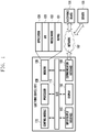
- FIG. 1 illustrates a network environment including an electronic device according to various embodiments of the present disclosure.
- the electronic device 101 includes a bus 110, a processor 120, a memory 130, an input/output interface 140, a display 150, a communication interface 160, and a control module 170.
- the bus 110 is a circuit connecting and transmitting communication between the above-described components.
- the processor 120 receives commands from other components of the electronic device 101 such as the memory 130, the input/output interface 140, the display 150, the communication interface 160, and/or the control module 170 through the bus 110, analyzes the received commands, and executes calculation or data processing according to the analyzed commands.
- the memory 130 stores commands or data received from or generated by the processor 120 or other components of the electronic device 101.
- the memory 130 includes a kernel 131, middleware 132, an application programming interface (API) 133, and an application 134.
- API application programming interface
- Each of the aforementioned programming modules may be implemented by software, firmware, hardware, or a combination thereof.
- the kernel 131 controls or manages system resources such as the bus 110, the processor 120, and/or the memory 130 used for executing an operation or function implemented by the other programming modules.
- the kernel 131 provides an interface for accessing individual components of the electronic device 101 from the middleware 132, the API 133, and/or the application 134 to control or manage the components.
- the middleware 132 performs a relay function of allowing the API 133 or the application 134 to communicate with the kernel 131 to exchange data. In operation requests received from the application 134, the middleware 132 performs a control for the operation requests, such as scheduling or load balancing, by assigning a priority by which system resources of the electronic device 101 can be used, to the application 134.
- the API 133 is an interface by which the application 134 can control a function provided by the kernel 131 or the middleware 132 and includes, for example, at least one interface or function for a file control, window control, image processing, or character control.
- the application 134 includes a short message service (SMS)/multimedia messaging service (MMS), email, calendar, alarm application, health care such as for measuring quantity of exercise or blood sugar, or environment information application such as for providing information on barometric pressure, humidity or temperature. Additionally or alternatively, the application 134 may be related to an information exchange between the electronic device 101 and an external electronic device 104, such as a notification relay application for transferring particular information to the external electronic device or a device management application for managing the external electronic device.
- SMS short message service
- MMS multimedia messaging service
- email calendar
- alarm application health care
- health care such as for measuring quantity of exercise or blood sugar
- environment information application such as for providing information on barometric pressure, humidity or temperature.
- environment information application such as for providing information on barometric pressure, humidity or temperature.
- the application 134 may be related to an information exchange between the electronic device 101 and an external electronic device 104, such as a notification relay application for transferring particular information to the external electronic device or a device management application for managing the external electronic device
- the notification relay application includes a function of transmitting notification information generated by another application of the electronic device 101 to the external electronic device 104. Additionally or alternatively, the notification relay application receives notification information from, for example, the external electronic device 104 and provides the received notification information to the user.
- the device management application manages at least a part of the functions of the external electronic device 104 communicating with the electronic device 101, an application executed in the external electronic device 104, and a service such as call or message service provided by the external electronic device 104.
- the application 134 is designated according to an attribute or type of the external electronic device 104.
- the application 134 is related to music reproduction.
- the application 134 is related to health care.
- the application 134 includes at least one of an application designated to the electronic device 101 and an application received from an external electronic device, such as the server 106 or electronic device 104.
- the input/output interface 140 transmits a command or data input from the user through an input/output device such as a sensor, keyboard, or touch screen to the processor 120, the memory 130, the communication interface 160, or the control module 170 through the bus 110.
- an input/output device such as a sensor, keyboard, or touch screen
- the input/output interface 140 provides data on a user's touch input through a touch screen to the processor 120, and outputs a command or data received, through the bus 110, from the processor 120, the memory 130, the communication interface 160, or the control module 170 through the input/output device such as a speaker or a display.
- the display 150 displays various pieces of information to the user.
- the communication interface 160 connects communication between the electronic device 101 and the external device.
- the communication interface 160 accesses a network 162 through wireless or wired communication to communicate with the external device.
- the wireless communication includes at least one of, for example, Wi-Fi, BLUETOOTH (BT), near field communication (NFC), a GPS, and cellular communication such as long term evolution (LTE), LTE-advanced (LTE-A), code division multiple access (CDMA), wideband CDMA (WCDMA), universal mobile telecommunications service (UMTS), wireless broadband (WiBro) or global system for mobile communications (GSM).
- the wired communication includes at least one of a universal serial bus (USB), a high definition multimedia interface (HDMI), recommended standard 232 (RS-232), and a plain old telephone service (POTS).
- USB universal serial bus
- HDMI high definition multimedia interface
- RS-232 recommended standard 232
- POTS plain old telephone service
- the network 162 is a telecommunication network including at least one of a computer network, Internet, Internet of things, and a telephone network.
- a protocol such as transport layer, data link layer, or physical layer protocol for communication between the electronic device 101 and the external device may be supported by at least one of the application 134, the API 133, the middleware 132, the kernel 131, and the communication interface 160.
- the input/output interface 140 and the display 150 may be integrally formed within a single device such as a touch screen.
- the control module 170 may be configured to control the display 150 to display a portion of content within a display area of the display 150.
- an area associated with the entire content configured to be displayed on the display 150 may be greater than the display area of the display 150.
- the portion of content displayed within the display area of the display 150 may include an object on the touch screen.
- the control module 170 may identify that the object is capable of being relocated within the content area. For example, the position of the object within the display area may be modified using a drag-and-drop operation where the object may be relocated to a portion of the content area not currently within the display area of the display 150.
- the display 150 of the touch screen displays only a portion of content within the display area and a remaining content is not currently visible within the display area of the display 150.
- the content area not currently displayed in the display area of the display 150 may be accessed using various techniques such as scrolling.
- the control module 170 may identify an object capable of being relocated within the content area different from an object not capable of being relocated with the content area based on the portion of the content currently displayed within the display area on the touch screen of the display 150.
- the control module 170 may classify an object capable of being relocated within the content area different from an object not capable of being relocated with the content area such that an object capable of being relocated within the content area may be distinguished from an object not capable of being relocated within the content area.
- the control module 170 may determine whether a predetermined touch input associated with an identified object is detected.
- the identified object means an object capable of being relocated within a content area (e.g., a draggable object).
- control module 170 may be configured to determine whether the detected touch input associated with the identified object is maintained for a predetermined time, determine whether the touch input is dragged more than a predetermined distance when the touch input is maintained for the predetermined time, and determine that the predetermined touch input is detected when the touch input is dragged more than the predetermined distance.
- the control module 170 may provide an indicator that is displayed with the display area of the display 150 that indicates the identified object can be dragged within the content area when the touch input detected on the identified object is maintained for the predetermined time and an input associated with a drag operation is not detected.
- the control module 170 may determine whether the detected touch input associated with the identified object is maintained for a predetermined time, determine whether the touch input is dragged over the display 150 at a predetermined speed when the touch input is maintained for the predetermined time, and determine that the detected touch input has been maintained for the predetermined time when the touch input is dragged over the display 150 at the predetermined speed.
- the control module 170 may determine whether an area to which the identified object can be dropped exists in the content area not currently displayed within the display area of the display 150 and control the display 150 to display the intended drop area (e.g. an area where the object could be dropped, for example, depending upon the object type and characteristics of the content identified as a potential drop area) corresponding to the detected area associated with the content area not currently displayed within the display area on the touch screen.
- the control module 170 may display a path from the identified object associated with the detected touch input to the detected area on the touch screen as a guide line.
- the control module 170 may determine at least one of a number, a location, and a size of the intended drop area of the content, and may adjust at least one of a number, a location, and a size of a drop area indicator so as to correspond to at least one of the determined number, location, and size and display the adjusted drop indicators on the touch screen.
- the amount of content area displayed within the touch screen may be increased to display a greater amount of content area including the intended drop area in which the object is to be dragged.
- the amount of content displayed within the display area of the display 150 may be increased (e.g., by zooming out) such that the intended drop area not previously displayed within the display area is included within the display area.
- the control module 170 may control a portion of the content area corresponding to the intended drop area to be within the display area of the display 150 and display content corresponding to the intended drop area within the display area of the touch screen.
- the control module 170 may control the display 150 to display content corresponding to the intended drop area such that the content corresponding to the intended drop area is overlapped with the portion of the content currently displayed within the display area of the touch screen.
- the control module 170 may display the remaining portion of content corresponding to the intended drop area to overlap with the currently content displayed on the touch screen.
- control module 170 may remove the drop area indicator from within the display area of the touch screen such that the drop area indicator may no longer be visible to a user within the display area of the touch screen.
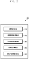
- FIG. 2 is a block diagram illustrating an electronic apparatus according to various embodiments of the present disclosure.
- the electronic apparatus 200 may include a control module 210, an identification module 220, a determination module 230, a detection module 240, and a display control module 250.
- the display control module 250 may be configured to control a display device to display a portion of content including an object within a display area of the touch screen.
- display control module 250 may be integrated with control module 170.
- display control module 250 may be completely separate from control module 170.
- display control module 250 may be configured to control display device 150 to display a portion of the content including an object.
- the content may include multimedia data, an application including at least one of text, video, or audio, etc.
- the object may include an object capable of being relocated within a content area (e.g., draggable object) or an object not capable of being relocated with a content area (e.g., a non-draggable object).
- a draggable object may modify the content after being relocated to a different portion of content area.
- the display control module 250 may be further configured to display the draggable object and the non-draggable object such that a user may visually distinguish between the draggable object and the non-draggable object.
- the portion of content displayed within a display area of a display may be less than a content area associated with the content.
- the content may be divided into at least two or more portions due to a limitation of the size of the display area of the display.
- any portion of the content may be displayed within the display area of the touch screen and the remaining portions of content may not be displayed within the display area of the touch screen.
- the remaining portion of content which is not displayed on the touch screen may be accessed and displayed on the touch screen according to a user's movement instruction such as a drag, a scroll, or the like.
- the content displayed within the display area of the touch screen may be a portion of content or a portion of the content area and the content not displayed within the display area of the touch screen may be a remaining portion of content or a remaining portion of the content area.
- the content may include at least one object including a draggable object or a non-draggable object.
- the content may include an intended area for dropping a dragged object.
- a draggable object, a non-draggable object, and/or an intended area for dropping the dragged object may be associated with the portion of the content currently displayed within the display area of a display or the remaining portion of content not currently displayed within the display area of a display.
- the display control module 250 may be configured to control the display of a display device such that that an identified object is draggable when the detected touch input associated with the identified object is maintained for a predetermined time and the drag touch input is not detected.
- a visual indicator may indicate that the object is draggable in various directions such as up, down, left, right.
- the display control module 250 may be configured to control the portion of the content displayed in the display area using up, down, left, and right arrow icons to indicate a potential navigation direction within the content area.
- the display control module 250 may be configured to control a display device such that a portion of the content area surrounding the draggable object is enlarged.
- the display control module 250 may be further configured to control a display device such that an area surrounding the intended drop area is enlarged. For example, by enlarging the content area surrounding the draggable object and/or enlarging the content area surrounding the intended drop area, a user may visually distinguish the draggable object and/or the intended drop area from other portions of the content.
- the display control module 250 may be further configured to control a display device such that the remaining portion of content corresponding to the intended drop area is displayed within the display area of the touch screen. For example, the portion of the content currently displayed within the display area may be moved outside the display area so it is no longer visible when the remaining portion of the content corresponding to the intended drop area is displayed within the display area.
- the display control module 250 may be configured to control a display device such that the remaining portion of content corresponding to the intended drop area is displayed to overlap the portion of the content currently displayed within the display area of the touch screen.
- the display control module 250 may control the display device to display the remaining portion of content corresponding to the drop area to overlap the touch screen.
- the display control module 250 may remove the drop area indicator from the touch screen. That is, the drop area indicator displayed on the touch screen may disappear from a user perspective.
- the display control module 250 may display the drop area corresponding to the remaining portion of content on the touch screen.
- the control module 210 may treat the object with the same process of dropping in the remaining portion of content.
- the display control module 250 may display a path from the object in which the touch input is detected to the intended drop area on the touch screen as a guide line. The user may drag the object to the intended drop area by dragging the touch input along the guide line.
- the identification module 220 may be configured to identify the draggable object from among a plurality of objects displayed on the touch screen.
- the identification module 220 may be configured to identify that the object is capable of being relocated within the content area where the object may be dragged from a portion of the content currently displayed within the display area to a portion of the remaining content not currently displayed within the display area of the touch screen.
- the identification module 220 may identify an object as a draggable object based on the type of content.
- the identification module 220 may be further configured to classify an object as a draggable object or a non-draggable object before the object is displayed within the display area of the touch screen or after the object is displayed within the display area of the touch screen.
- the determination module 230 may be configured to determine whether a detected touch input is associated with the identified object.
- the touch input may be a predetermined touch input previously set by a user or the electronic apparatus 200.
- the determination module 230 may be configured to define a drag-and-drop input pattern or a flicking input pattern as the predetermined touch input.
- the determination module 230 may be further configured to determine whether the touch input associated with the identified object is maintained for a predetermined time. When it is determined that the touch input is maintained for the predetermined time, the determination module 230 may determine whether the touch input pattern indicates that the object is dragged more than a predetermined distance.
- the determination module 230 may determine that the detected touch input is the predetermined touch input.
- the predetermined time may be used to determine whether the touch input is an input of long press, e.g., the time in which the touch input is detected exceeds two seconds.
- the predetermined distance may be based on the size or the area of the touch screen. For example, the predetermined distance may be in the range of 2-5 cm. In an exemplary embodiment, a first predetermined distance such as 2-3 cm may be associated with a first touch screen and a second predetermined distance such as 3-5 cm may be associated with a second touch screen where the size or area of the second touch screen is greater than the size or area of the first touch screen.
- the determination module 230 may be configured to determine whether the touch input is dragged more than a predetermined speed and determine that the touch input is the predetermined touch input when the detected touch input is dragged more than the predetermined speed.
- the predetermined speed may be based on the touch input speed associated with a flicking input pattern.
- the detection module 240 may be configured to detect whether an area in which the identified object is intended to be dropped exists in the remaining portion of content. In various embodiments of the present disclosure, the detection module 240 may determine at least one of a number, a location, and a size of the intended drop area. The detection module 240 may adjust at least one of a number, a location, and a size of the intended drop area so as to correspond to at least one of the determined number, location, and size.
- the electronic apparatus may include a touch screen configured to display a portion of content including an object and a control module configured to identify the object as a draggable object, determine whether a predetermined touch input associated with the identified object is detected, determine whether an intended drop area associated with the identified object exists in a remaining portion of content when the predetermined touch input is detected, and display a drop area indicator corresponding to the intended drop area on the touch screen.
- the control module identifies an object that can be dragged to the remaining portion of content deviated from the touch screen from among a plurality of objects displayed on the touch screen.
- the control module identifies a draggable object differently depending on the type of content displayed.
- the control module determines whether the touch input associated with the identified object is maintained for a predetermined time, determines whether the touch input is dragged more than a predetermined distance when the touch input is maintained for the predetermined time, and determines that the predetermined touch input is detected when the touch input is dragged more than the predetermined distance.
- the control module displays that the identified object can be dragged when the touch input detected on the identified object is maintained for the predetermined time and the drag of the touch input is not detected.
- the control module determines whether the touch input associated with the identified object is maintained for a predetermined time, determines whether the touch input is dragged over a predetermined speed when the touch input is maintained for the predetermined time, and determines that the predetermined touch input is detected when the touch input is dragged over the predetermined speed.
- the control module controls to identify a non-draggable object displayed on the touch screen and displays the draggable object to be distinguished from the non-draggable object.
- the control module controls to determine at least one of a number, a location, and a size of an intended drop area and adjusts at least one of a number, a location, and a size of the drop area indicators so as to correspond to at least one of the determined number, location, and size of the intended drop area, and displays the adjusted drop area indicators on the touch screen.
- the control module may display a path from the object in which the touch input is detected to the intended drop area on the touch screen as a guide line.
- the touch screen enlarges and displays a size of the intended drop area to which the object is dragged when the touch input associated with the object is dragged to the drop area indicator.
- the control module controls to move the remaining portion of content corresponding to the intended drop area when the touch input detected on the object is dragged to the drop area indicator and displays the remaining portion of content corresponding to the intended drop area on the touch screen.
- the control module controls to display the remaining portion of content corresponding to the intended drop area to overlap with the touch screen when the touch input associated with the object is dragged to the drop area indicator.
- the control module controls to display the remaining portion of content corresponding to the intended drop area to overlap with the touch screen when the number of the drop area indicators is more than a predetermined number.
- the control module controls to remove the drop area indicator from the touch screen when the touch input associated with the object is dragged to an area which is not associated with the drop area indicator.
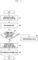
- FIG. 3 illustrates a flow chart of an exemplary method of processing a drag and drop input according to various embodiments of the present disclosure.
- the method will be discussed with reference to the exemplary electronic apparatus 101 illustrated in FIG. 1 or the exemplary electronic apparatus 200 illustrated in FIG. 2 .
- the method can be implemented with any suitable electronic apparatus.
- FIG. 3 depicts steps performed in a particular order for purposes of illustration and discussion, the methods discussed herein are not limited to any particular order or arrangement.
- One skilled in the art, using disclosures provided herein, will appreciate that various steps of the methods can be omitted, rearranged, combined and/or adapted in various ways.
- a portion of content including an object may be displayed within a display area of a touch screen.
- the display control module 250 may be configured to control a display device such as display 150 to display a portion of content within a display area of the touch screen associated with the display device.
- the content may include multimedia data, an application including at least one of text, video, or audio, etc.
- the web page may be displayed on a large display apparatus such as a full size monitor connected to a laptop or desk top computer where a user may view the entire content area of the web page on the display device.
- the same web page may not be fully displayed within the display area of the display device of the electronic apparatus 101 or 200 and only a portion of the web page may be viewed within the display area of the touch screen.
- the remaining portion of the web page which is not visible within the display area of the touch screen may be displayed within the display area of the touch screen based on a touch input received at the touch screen such as a drag, a scroll, or the like.
- the content may include one or more objects and an object may a draggable object or a non-draggable object.
- the object when the object is an image, the image may be draggable or non-draggable.
- a draggable object may modify the content after being relocated to a different portion of content area.
- the type of touch input may be different depending on the type of content displayed within the display area.
- a draggable object may be identified.
- the electronic apparatus 101 or 200 may identify whether or not the object displayed within a display area can be dragged to a remaining portion of content.
- identification module 220 may identify the draggable object based on the type of content displayed within the display area of a touch screen.
- the electronic apparatus 101 or 200 may be configured to control the touch screen to display the draggable object differently from a non-draggable object.
- the electronic apparatus 101 or 200 may be configured to control the touch screen such that a draggable object may be visually distinguishable from a non-draggable object.
- the touch screen may display the draggable object more prominently than the non-draggable object.
- the edge of the draggable object may be colored, for example, in red, blue, and the like or the draggable object may be flickered.
- the user may visually distinguish between the draggable object and the non-draggable object.
- a predetermined touch input associated with an identified object may be determined.
- electronic apparatus 101 or 200 may determine whether a predetermined touch input is associated with an identified object is detected.
- the predetermined touch input may be previously set by a user or the electronic apparatus 200.
- the predetermined touch input may be a drag and drop input pattern or a flicking input pattern.
- the electronic apparatus 101 or 200 may determine whether the detected touch input associated with the identified object is maintained for a predetermined time.
- the predetermined time may be used to determine whether the touch input is a long press, e.g., the time in which the touch input is detected exceeds two seconds.
- the electronic apparatus 101 or 200 may determine whether the touch input is dragged more than a predetermined distance and may determine that the predetermined touch input is detected when the touch input is dragged more than the predetermined distance.
- the predetermined distance may be based on the size or the area of the touch screen. For example, the predetermined distance may be in the range of 2-5 cm. In an exemplary embodiment, a first predetermined distance such as 2-3 cm may be associated with a first touch screen and a second predetermined distance such as 3-5 cm may be associated with a second touch screen where the size or area of the second touch screen is greater than the size or area of the first touch screen.
- the electronic apparatus 101 or 200 may be configured to control a display device such that the identified object is draggable from a first portion of content to a second portion of content when the detected touch input associated with the object is maintained for a predetermined time and the drag of the touch input is not detected.
- the display control module 250 may control the display to include indicators such as up, down, left, right arrows respectively.
- the electronic apparatus 101 or 200 may determine whether a touch input is maintained for the predetermined time, whether the touch input is dragged more than a predetermined speed, and that the predetermined touch input is detected when the touch input is dragged more than the predetermined speed.
- the predetermined speed may be based on the input speed associated with a flicking input operation.
- the electronic apparatus 101 or 200 may detect whether an area in which the identified object is intended to be dropped exists in the remaining portion of content.
- the intended area in which the identified object can be dropped is an area of the content in which the dragged object can be dropped and may be detected in the remaining portion of content.
- the electronic apparatus 101 or 200 may perform a function corresponding to the detected touch input at operation 360.
- the intended drop area may be displayed in the display area.
- the electronic apparatus 101 or 200 may display an area of content corresponding to an intended drop area within the display area of the touch screen.
- the intended drop area may correspond to the area detected from the remaining portion of content and may be displayed on the touch screen for user convenience.
- the electronic apparatus 101 or 200 may treat the object with the same process of dropping in the remaining portion of content.
- the electronic apparatus 101 or 200 may display a path from the object in which the touch input is detected to the intended drop area on the touch screen as a guide line where the user may drag the object to the intended drop area conveniently by dragging the touch input along the guide line.
- the electronic apparatus 101 or 200 may determine at least one of a number, a location, and a size of the intended drop area and may adjust at least one of a number, a location, and a size of a drop area indicator so as to correspond to at least one of the determined number, location, and size of the intended drop area and display the adjusted drop area indicator on the touch screen.
- the electronic apparatus may display three drop area indicators on the touch screen when the number of intended drop areas is three.
- the electronic apparatus may extract the location of the intended drop area into a coordinate value and may change the location of the drop area indicator so as to correspond to the coordinate value associated with the intended drop area.
- the electronic apparatus may adjust the size of the drop area indicator to be enlarged when the size of the intended drop area is large and may adjust the size of the drop area indicator to be reduced when the size of the intended drop area is small.
- the method of processing a drag and drop touch input includes displaying a portion of content including an object on the touch screen, identifying a draggable object among the object, determining whether a predetermined touch input associated with the identified object is detected, determining whether an intended drop area associated with the identified object exists in a remaining portion of content when the predetermined touch input is detected, and displaying a drop area indicator corresponding to the intended drop area on the touch screen.
- Identifying a draggable object includes identifying an object that can be dragged to the remaining portion of content not displayed on the touch screen from among the object displayed on the touch screen.
- Determining whether a predetermined touch input is detected includes determining whether the detected touch input associated with the identified object is maintained for a predetermined time, determining whether the touch input is dragged more than a predetermined distance when the touch input is maintained for the predetermined time, and determining that the predetermined touch input is detected when the touch input is dragged more than the predetermined distance.
- Determining whether a predetermined touch input is detected includes displaying a visual indicator that the identified object can be dragged when the touch input detected on the identified object is maintained for the predetermined time and the drag of the touch input is not detected.
- Determining whether a predetermined touch input is detected includes: determining whether the detected touch input associated with the identified object is maintained for a predetermined time, determining whether the touch input is dragged over a predetermined speed when the touch input is maintained for the predetermined time, and determining that the predetermined touch input is detected when the touch input is dragged over the predetermined speed.
- Determining whether a predetermined touch input is detected includes: identifying a non-draggable object displayed on the touch screen and displaying the draggable object to be distinguished from the non-draggable object.
- Determining whether an area in which the identified object can be dropped exists includes checking at least one of a number, a location, and a size of an intended drop area. Displaying a drop area indicator corresponding to the intended drop area includes adjusting at least one of the number, the location, and the size of the drop area indicator so as to correspond to at least one of the determined number, location, and size of the intended drop area and displaying the adjusted drop area indicator on the touch screen.
- Displaying of the drop area indicator includes displaying a path from the object in which the touch input is detected to the intended drop area on the touch screen as a guide line.
- the method further includes enlarging and displaying a size of the intended drop area in which the object is dragged when the touch input associated with the object is dragged to the drop area indicator.
- the method further includes moving to the remaining portion of content corresponding to the intended drop area when the touch input associated with the object is dragged to the drop area indicator and displaying the remaining portion of content corresponding to the intended drop area on the touch screen.
- the method further includes displaying the remaining portion of content corresponding to the intended drop area to overlap with the touch screen when the touch input associated with the object is dragged to the drop area indicator.
- Displaying of the drop area indicator includes displaying the remaining portion of content corresponding to the drop area to overlap with the touch screen when a number of the drop area indicators is more than a predetermined number.
- the method further includes removing a drop area indicator from the touch screen when the touch input associated with the object is dragged to an area which is not associated the drop area indicator.
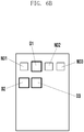
- FIGS. 4A and 4B illustrate examples of displaying a drop area in a touch screen according to various embodiments of the present disclosure.
- a rectangular area illustrated as 'CA' may form a single content area.
- the entire content area CA may be displayed on a single screen at the same time.
- an electronic apparatus may display only a portion of content within a display area DA of a touch screen.
- the portion of content displayed in the display area DA of the touch screen is illustrated as 'S' and the remaining portion of content not displayed within the display area DA of the touch screen is illustrated as 'R'.
- the portion of content S is displayed within the display area DA of the touch screen, the remaining portion R of the content is not displayed on the touch screen.
- an input such as a drag, a scroll, or the like is detected, the portion of content R may be displayed on the touch screen.
- the electronic apparatus may identify an object 'O' within the portion of content S displayed in the display area DA.
- the electronic apparatus may identify whether the object O is a draggable object or a non-draggable object.
- the electronic apparatus may determine whether a predetermined touch input associated with the object O is detected.
- the electronic apparatus may determine whether an area to which the object O is intended to be dropped exists in the remaining portion R of content.
- the electronic apparatus may detect intended areas A1 to A3, as areas in which the object O is intended be dropped within the remaining portion R of the content area CA.
- the electronic apparatus may display a drop area indicator corresponding to the intended drop areas (A1 to A3). For example, referring to FIG.
- the electronic apparatus may display a first drop area indicator as DA1 where DA1 corresponds to the intended drop area A1, a second drop area indicator as DA2 where DA2 corresponds to the intended drop area A2, and a third drop area indicator DA3 where DA3 corresponds to the intended drop area A3.
- DA1 corresponds to the intended drop area A1
- DA2 corresponds to the intended drop area A2
- DA3 corresponds to the intended drop area A3
- FIG. 4A illustrates three intended drop areas and three corresponding drop area indicators, any number of intended drop areas and/or drop area indicators may be provided.
- the electronic apparatus may determine whether a predetermined touch input associated with the object O is detected when the object O is a draggable object.
- the electronic apparatus may determine whether an area to which the identified object O may be dropped exists in the remaining portion R of content.
- the electronic apparatus may display a path from the object O in which the touch input is detected to the intended drop areas (A1 to A3) in the remaining portion R of content as a guide line (GL1 to GL3) on the touch screen.
- the electronic apparatus may display a first guide line GL1 from the object O to the intended drop area A1, a second guide line GL2 from the object O to the intended drop area A2, and a third guide line GL3 from the object O to the intended drop area A3.
- FIGS. 5A to 5C illustrate examples of identifying a draggable object according to various embodiments of the present disclosure.
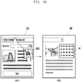
- FIG. 5A illustrates an example of displaying a web page as content.
- the entire web page is the content area CA and only a portion of the web page S may be displayed within the display area DA of the touch screen at one time where the remaining portion of the web page R cannot be displayed within the display area DA of the touch screen.
- the electronic apparatus may identify an object as a draggable object associated with the content displayed within the display area DA of the touch screen.
- the electronic apparatus may identify draggable objects (D1 to D3) depending on a characteristic of the web page.
- the draggable objects (D1 to D3) may be different depending on the characteristic of the web page such as text, image, video, etc.
- the draggable objects D1 to D3 may include text.
- draggable object D1 is an identifier associated with the web page such as a URL address
- draggable object D2 is associated with a search box
- draggable object D3 includes text content associated with the web page.
- FIG. 5B illustrates an example of displaying a home screen of the electronic apparatus as content.
- the home screen may be a background screen of the electronic apparatus.
- the home screen may be configured to include three portions of content.
- the objects included in the first portion home screen S may include a draggable object (D1 to D3) and a non-draggable object (ND1 to ND3).
- the electronic apparatus may visually differentiate the draggable objects (D1 to D3) from the non-draggable objects (ND1 to ND3) when the draggable objects (D1 to D3) are within the display area DA of the touch screen.
- the object within the home screen may be displayed as a rectangle where each rectangle includes an icon of an application.
- the electronic apparatus may display the edge of the draggable objects (D1 to D3) bolder than the non-draggable objects (ND1 to ND3) so that a draggable object (D1 to D3) may be visually distinguishable from a non-draggable object (ND1 to ND3).
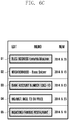
- FIG. 5C illustrates an example of displaying a screen executing a memo function as content.
- the electronic apparatus may not display the whole memo within the display area DA of the touch screen.
- the portions of content of the memo displayed on the touch screen are illustrated as S and the remaining portion of the content of the memo not displayed on the touch screen is illustrated as R.
- the electronic apparatus may identify the draggable objects (D1 to D5) associated with the memo displayed within the display area DA of the touch screen.
- the draggable objects (D1 to D5) may be the contents of the memo. Since the memo may be edited by a user, all of the content of memo may be the draggable objects (D1 to D5).
- FIGS. 6A to 6C illustrate examples of displaying a draggable object discriminatively according to various embodiments of the present disclosure.
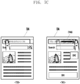
- FIG. 6A illustrates an example of displaying a web page as content.
- the electronic apparatus may identify the draggable objects (D1 to D3) and the non-draggable objects (ND1, ND2) displayed within the display area DA of the touch screen.
- the electronic apparatus may display the draggable objects (D1 to D3) such that the draggable objects (D1 to D3) are visually distinguishable from the non-draggable objects (ND1, ND2).
- the electronic apparatus may display the draggable objects (D1 to D3) to be shaded such that the shaded draggable objects (D1 to D3) may be visually distinguishable from the non-draggable objects (ND1, ND2).
- FIG. 6B illustrates an example of displaying a home screen of the electronic apparatus as content.
- the electronic apparatus may identify the draggable objects (D1 to D3) and the non-draggable objects (ND1, ND2) displayed within the display area DA of the touch screen.
- the electronic apparatus may display the draggable objects (D1 to D3) to be larger than the non-draggable objects (ND1, ND2) such that the draggable objects (D1 to D3) may be visually distinguishable from the non-draggable objects (ND1, ND2).
- FIG. 6C illustrates an example of displaying a screen executing a memo function as a content.
- the electronic apparatus may display the draggable objects (D1 to D5) within the display area DA of the touch screen to be flickered where "to be flickered” may mean periodically modifying a brightness level of the display associated with the draggable objects (D1 to D5).
- draggable objects (D1, D3, D5) are illustrated as having a high brightness level and draggable objects (D2, D4) are illustrated as having a low brightness level.
- the electronic apparatus may repeatedly turn light on and off periodically to display objects to be flickered.
- a user may visually recognize the draggable objects through only a screen displayed within the display area DA of the touch screen, as shown in FIGS. 6A and 6C .
- FIGS. 7A to 7C illustrates examples of determining whether a predetermined touch input is detected according to various embodiments of the present disclosure.
- the electronic apparatus may determine whether a touch input associated with the identified object is maintained for a predetermined time as shown in reference numeral 710.
- the predetermined time may be used to determine whether the touch input is a long press, e.g., the time in which the touch input is detected exceeds two seconds.
- the electronic apparatus may determine whether the touch input is dragged more than a predetermined distance L.
- the electronic apparatus may determine that the predetermined touch input is detected and may display the drop area indicators (DA1, DA2) within the display area DA of the touch screen.
- the predetermined distance L may be based on the size or the area of the touch screen.
- the predetermined distance may be in the range of 2-5 cm.
- a first predetermined distance such as 2-3 cm may be associated with a first touch screen and a second predetermined distance such as 3-5 cm may be associated with a second touch screen where the size or area of the second touch screen is greater than the size or area of the first touch screen.
- the electronic apparatus may display that the identified object displayed within the display area DA is draggable when a detected touch input associated with the object is maintained for a predetermined time and the drag of the touch input is not detected.
- up, down, left, and right arrows may be display to indicate that the object can be moved to up, down, left, right.
- the electronic apparatus may display a drop area indicator DA1 corresponding to an intended drop area in the remaining portion of content not displayed within the display area DA of the touch screen.
- the electronic apparatus may determine whether the detected touch input associated with the identified object is maintained for a predetermined time as shown in reference numeral 730.
- the electronic apparatus may determine whether the touch input is dragged over a predetermined speed within the display area DA, when the touch input is maintained for the predetermined time.
- the electronic apparatus may determine that the predetermined touch input is detected, and display the drop area indicators DA1, DA2 corresponding to the intended drop areas in the remaining portion of content not displayed within the display area DA of the touch screen as shown in reference numeral 740.
- the predetermined speed may be based on an input speed associated with a flicking input pattern.
- FIGS. 8A to 8C illustrate examples of dragging an object into an intended drop area according to various embodiments of the present disclosure.
- the electronic apparatus may enlarge and display the size of the intended drop area DA2 or the drop area indicator DA1 to which the object is dragged as shown in reference numeral 810.
- the electronic apparatus may enlarge and display the size of the intended drop area DA2 to which the object is to be dragged within the display area DA such that user may visually identify the intended drop area DA2.
- the electronic apparatus may move to the remaining portion A2 of content corresponding to the intended drop area DA2 to display the remaining portion A2 of content corresponding to the intended drop area as shown in reference numeral 820.
- the electronic apparatus may automatically move to the remaining portion A2 of content corresponding to the intended drop area DA2 and display the remaining portion, thereby improving user's convenience.
- the electronic apparatus may display the remaining portion of content corresponding to the intended drop area IDA2 such that the dragged object overlaps the intended drop area DA2 within the display area DA of the touch screen as shown in reference numeral 840.
- the electronic apparatus may display the remaining portion of content corresponding to the intended drop areas in an overlapping manner within the display area DA of the touch screen.
- the electronic apparatus may move to the remaining portion of content corresponding to the intended drop area and may display the remaining portion of content within the display area DA of the touch screen.
- the electronic apparatus may discontinue displaying the drop area indicators DA1, DA2 on the touch screen as shown in reference numeral 860. For example, when the detected touch input associated with the object is dragged to the area 850 which is not associated with a drop area indicator DA1, DA2, the electronic apparatus may return to the state before the touch input is detected where the drop area indicators DA1, DA2 are no longer displayed.
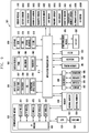
- FIG. 9 is a block diagram of an electronic device according to various embodiments of the present disclosure.
- the electronic device 901 configures all or a part of the electronic device 101 illustrated in FIG. 1 .
- the electronic device 901 includes one or more application processors (APs) 910, a communication module 920, a subscriber identification module (SIM) card 924, a memory 930, a sensor module 940, an input device 950, a display module 960, an interface 970, an audio module 980, a camera module 991, a power-managing module 995, a battery 996, an indicator 997, and a motor 998.
- APs application processors
- SIM subscriber identification module
- the AP 910 operates an operating system (OS) or an application program so as to control a plurality of hardware or software component elements connected to the AP 910 and executes various data processing and calculations including multimedia data.
- the AP 910 may be implemented by a system on chip (SoC).
- SoC system on chip
- the AP 910 may further include a graphics processing unit (GPU).
- the communication module 920 transmits/receives data in communication between different electronic devices such as the electronic device 104 and the server 106 connected to the electronic device 901 through a network 162.
- the communication module 920 includes a cellular module 921, a Wi-Fi module 923, a BT module 925, a GPS module 927, an NFC module 928, and a radio frequency (RF) module 929.
- RF radio frequency
- the cellular module 921 provides a voice, a call, a video call, SMS, or an Internet service through a communication network.
- the cellular module 921 distinguishes and authenticates electronic devices within a communication network by using a SIM card 924.
- the cellular module 921 performs at least some of the functions that can be provided by the AP 910, such as the multimedia control functions.
- the cellular module 921 includes a communication processor (CP).
- the cellular module 921 may be implemented by, for example, an SoC.
- the components such as the cellular module 921, the memory 930, and the power-managing module 995 are illustrated as components separate from the AP 910 in FIG. 9 , the AP 910 includes at least some of the aforementioned components.
- the AP 910 or the cellular module 921 loads a command or data received from at least one of a non-volatile memory and other components connected to each of the AP 910 and the cellular module 921 to a volatile memory and processes the loaded command or data.
- the AP 910 or the cellular module 921 stores data received from at least one of other components or generated by at least one of other components in a non-volatile memory.
- Each of the Wi-Fi module 923, the BT module 925, the GPS module 927, and the NFC module 928 includes, for example, a processor for processing data transmitted/received through the corresponding module.
- the cellular module 921, the Wi-Fi module 923, the BT module 925, the GPS module 927, and the NFC module 928 are illustrated as blocks separate from each other in FIG. 9 , at least two of the cellular module 921, the Wi-Fi module 923, the BT module 925, the GPS module 927, and the NFC module 928 may be included in one integrated chip (IC) or one IC package according to an embodiment of the present disclosure.
- IC integrated chip
- at least some of the processors corresponding to the cellular module 921, the Wi-Fi module 923, the BT module 925, the GPS module 927, and the NFC module 928 may be implemented by one SoC.
- the RF module 929 transmits/receives data such as an RF signal.
- the RF module 929 includes, for example, a transceiver, a power amp module (PAM), a frequency filter, and a low noise amplifier (LNA).
- the RF module 929 may further include a component for transmitting/receiving electronic waves over a free air space in wireless communication, such as a conductor or a conducting wire.
- the cellular module 921, the Wi-Fi module 923, the BT module 925, the GPS module 927, and the NFC module 928 share one RF module 929 in FIG. 9 , at least one of the modules may transmit/receive an RF signal through a separate RF module according to an embodiment of the present disclosure.
- the SIM card 924 is inserted into a slot 926 formed in a particular portion of the electronic device, and includes unique identification information such as an integrated circuit card identifier (ICCID) or subscriber information such as an international mobile subscriber identity (IMSI).
- ICCID integrated circuit card identifier
- IMSI international mobile subscriber identity
- the memory 930 includes an internal memory 932 or an external memory 934.
- the internal memory 932 includes, for example, at least one of a volatile memory such as a random access memory (RAM), a dynamic RAM (DRAM), a static RAM (SRAM), and a synchronous DRAM (SDRAM), and a non-volatile Memory such as a read only memory (ROM), a one-time programmable ROM (OTPROM), a programmable ROM (PROM), an erasable and programmable ROM (EPROM), an electrically erasable and programmable ROM (EEPROM), a mask ROM, a flash ROM, a NAND flash memory, and a NOR flash memory.
- ROM read only memory
- OTPROM one-time programmable ROM
- PROM programmable ROM
- EPROM erasable and programmable ROM
- EEPROM electrically erasable and programmable ROM
- the internal memory 932 may be a solid state drive (SSD).
- the external memory 934 may further include a flash drive such as a compact flash (CF), a secure digital (SD), a Micro-SD, a Mini-SD, an extreme digital (xD), or a memory stick.
- the external memory 934 may be functionally connected to the electronic device 901 through various interfaces.
- the electronic device 901 may further include a storage device such as a hard drive.
- the sensor module 940 measures a physical quantity or detects an operation state of the electronic device 101, and converts the measured or detected information to an electronic signal.
- the sensor module 940 includes a gesture sensor 940A, a gyro sensor 940B, an atmospheric pressure (barometric) sensor 940C, a magnetic sensor 940D, an acceleration sensor 940E, a grip sensor 940F, a proximity sensor 940G, a color sensor 940H (for example, red, green, and blue (RGB) sensor) 1140H, a biometric sensor 940I, a temperature/humidity sensor 940J, an illumination (light) sensor 940K, and an ultraviolet (UV) sensor 940M.
- a gesture sensor 940A a gyro sensor 940B, an atmospheric pressure (barometric) sensor 940C, a magnetic sensor 940D, an acceleration sensor 940E, a grip sensor 940F, a proximity sensor 940G, a color sensor 940H (for example, red
- the sensor module 940 may include an E-nose sensor, an electromyography (EMG) sensor, an electroencephalogram (EEG) sensor, an electrocardiogram (ECG) sensor, an infrared (IR) sensor, an iris sensor, and a fingerprint sensor (not illustrated).
- the sensor module 940 may further include a control circuit for controlling one or more sensors included in the sensor module 940.
- the input device 950 includes a touch panel 952, a (digital) pen sensor 954, a key 956, and an ultrasonic input device 958.
- the touch panel 952 recognizes a touch input in at least one of a capacitive, resistive, infrared, and acoustic wave type.
- the touch panel 952 may further include a control circuit. In the capacitive type, the touch panel 952 can recognize proximity as well as a direct touch.
- the touch panel 952 may further include a tactile layer that provides a tactile reaction to the user.
- the (digital) pen sensor 954 may be implemented, for example, using a method identical or similar to a method of receiving a touch input of the user, or using a separate recognition sheet.
- the key 956 includes, for example, a physical button, an optical key, or a key pad.
- the ultrasonic input device 958 detects an acoustic wave by a microphone 988 of the electronic device 901 through an input means generating an ultrasonic signal to identify data and performs wireless recognition.
- the display 960 (for example, display 150) includes a panel 962, a hologram device 964, and a projector 966.
- the panel 962 may be, for example, a liquid crystal display (LCD) or an active matrix organic light emitting diode (AM-OLED).
- the panel 962 may be implemented to be, for example, flexible, transparent, or wearable.
- the panel 962 may be configured by the touch panel 952 and one module.
- the hologram device 964 shows a stereoscopic image in the air by using interference of light.
- the projector 966 projects light on a screen to display an image.
- the screen may be located inside or outside the electronic device 901.
- the display 960 may further include a control circuit for controlling the panel 962, the hologram device 964, and the projector 966.
- the interface 970 includes, for example, an HDMI 972, a USB 974, an optical interface 976, and a D-subminiature (D-sub) 978.
- the interface 970 may be included in, for example, the communication interface 160 illustrated in FIG. 1 . Additionally or alternatively, the interface 970 may include, for example, a mobile high-definition link (MHL) interface, an SD card/multi-media card (MMC), or an infrared data association (IrDA) standard interface.
- MHL mobile high-definition link
- MMC SD card/multi-media card
- IrDA infrared data association
- the audio module 980 bi-directionally converts a sound and an electronic signal. At least some components of the audio module 980 may be included in, for example, the input/output interface 140 illustrated in FIG. 1 .
- the audio module 980 processes sound information input or output through, for example, a speaker 982, a receiver 984, an earphone 986, the microphone 988 or the like.
- the camera module 991 is a device which can photograph a still image and a video.
- the camera module 991 may include one or more image sensors (for example, a front sensor or a back sensor), an image signal processor (ISP) (not shown) or a flash (for example, an LED or xenon lamp).
- ISP image signal processor
- flash for example, an LED or xenon lamp
- the power managing module 995 manages power of the electronic device 901.
- the power managing module 995 may include, for example, a power management integrated circuit (PMIC), a charger IC, or a battery or fuel gauge.
- PMIC power management integrated circuit
- the PMIC may be mounted to, for example, an integrated circuit or an SoC semiconductor.
- a charging method may be divided into wired and wireless methods.
- the charger IC charges a battery and prevent over voltage or over current from flowing from a charger.
- the charger IC includes a charger IC for at least one of the wired charging method and the wireless charging method.
- the wireless charging method may include, for example, a magnetic resonance method, a magnetic induction method and an electromagnetic wave method, and additional circuits for wireless charging, for example, circuits such as a coil loop, a resonant circuit, a rectifier or the like may be added.
- the battery fuel gauge measures, for example, a remaining quantity of the battery 996, or a voltage, a current, or a temperature during charging.
- the battery 996 may store or generate electricity and supply power to the electronic device 901 by using the stored or generated electricity.
- the battery 996 may include a rechargeable battery or a solar battery.
- the indicator 997 shows particular statuses of the electronic device 901 or a part (for example, AP 910) of the electronic device 901, for example, a booting status, a message status, a charging status and the like.
- the motor 998 converts an electrical signal to a mechanical vibration.
- the electronic device 901 may include a processing unit (for example, GPU) for supporting a module TV.
- the processing unit for supporting the mobile TV may process, for example, media data according to a standard of digital multimedia broadcasting (DMB), digital video broadcasting (DVB), media flow or the like.
- DMB digital multimedia broadcasting
- DVD digital video broadcasting
- Each of the components of the electronic device according to various embodiments of the present disclosure may be implemented by one or more components and the name of the corresponding component may vary depending on a type of the electronic device.
- the electronic device according to various embodiments of the present disclosure may include at least one of the above described components, a few of the components may be omitted, or additional components may be further included. Also, some of the components of the electronic device according to various embodiments of the present disclosure may be combined to form a single entity, and thus may equivalently execute functions of the corresponding components before being combined.
- embodiments of the present invention can be realized in the form of hardware, software or a combination of hardware and software. Any such software may be stored in the form of volatile or non-volatile storage, for example a storage device like a ROM, whether erasable or rewritable or not, or in the form of memory, for example RAM, memory chips, device or integrated circuits or on an optically or magnetically readable medium, for example a CD, DVD, magnetic disk or magnetic tape or the like. It will be appreciated that the storage devices and storage media are embodiments of machine-readable storage that are suitable for storing a program or programs comprising instructions that, when executed, implement embodiments of the present invention.
- embodiments provide a program comprising code for implementing apparatus or a method as claimed in any one of the claims of this specification and a machine-readable storage storing such a program. Still further, such programs may be conveyed electronically via any medium, for example a communication signal carried over a wired or wireless connection and embodiments suitably encompass the same.
Landscapes
- Engineering & Computer Science (AREA)
- General Engineering & Computer Science (AREA)
- Theoretical Computer Science (AREA)
- Human Computer Interaction (AREA)
- Physics & Mathematics (AREA)
- General Physics & Mathematics (AREA)
- User Interface Of Digital Computer (AREA)
Applications Claiming Priority (1)
| Application Number | Priority Date | Filing Date | Title |
|---|---|---|---|
| KR1020140104993A KR102319286B1 (ko) | 2014-08-13 | 2014-08-13 | 드래그 앤 드롭 처리 방법 및 장치 |
Publications (2)
| Publication Number | Publication Date |
|---|---|
| EP2988198A1 EP2988198A1 (en) | 2016-02-24 |
| EP2988198B1 true EP2988198B1 (en) | 2018-11-07 |
Family
ID=53879373
Family Applications (1)
| Application Number | Title | Priority Date | Filing Date |
|---|---|---|---|
| EP15180717.9A Active EP2988198B1 (en) | 2014-08-13 | 2015-08-12 | Apparatus and method for processing drag and drop |
Country Status (5)
| Country | Link |
|---|---|
| US (1) | US10838612B2 (ko) |
| EP (1) | EP2988198B1 (ko) |
| KR (1) | KR102319286B1 (ko) |
| CN (1) | CN106575197B (ko) |
| WO (1) | WO2016024835A1 (ko) |
Families Citing this family (8)
| Publication number | Priority date | Publication date | Assignee | Title |
|---|---|---|---|---|
| US10102824B2 (en) * | 2015-05-19 | 2018-10-16 | Microsoft Technology Licensing, Llc | Gesture for task transfer |
| US10413814B2 (en) * | 2017-06-09 | 2019-09-17 | Supercell Oy | Apparatus and method for controlling user interface of computing apparatus |
| US10770037B2 (en) * | 2018-03-15 | 2020-09-08 | Kyocera Document Solutions Inc. | Mobile terminal device |
| JP7265394B2 (ja) * | 2019-03-26 | 2023-04-26 | 東芝テック株式会社 | 監視システム |
| CN111552428B (zh) * | 2020-04-29 | 2021-12-14 | 腾讯科技(深圳)有限公司 | 数据处理方法、装置、计算机设备以及存储介质 |
| KR20230022740A (ko) * | 2021-08-09 | 2023-02-16 | 삼성전자주식회사 | 전자 장치 및 객체의 움직임 동작을 개선하는 방법 |
| KR102443123B1 (ko) | 2022-06-02 | 2022-09-15 | 크리온 주식회사 | 휴대단말기 제어방법 |
| KR20240094385A (ko) | 2022-12-16 | 2024-06-25 | 주식회사 에이텍 | 음파 진동을 이용한 터치스크린 오동작 방지장치 및 방법 |
Family Cites Families (30)
| Publication number | Priority date | Publication date | Assignee | Title |
|---|---|---|---|---|
| US6002402A (en) * | 1997-04-09 | 1999-12-14 | Symantec Corporation | System and method for producing a drag-and-drop object from a popup menu item |
| US8907904B2 (en) * | 2010-10-01 | 2014-12-09 | Z124 | Smartpad split screen desktop |
| DE102004012897B4 (de) | 2004-03-16 | 2006-01-12 | Siemens Ag | Verfahren zur Darstellung von Grafikobjekten und Kommunikationsgerät |
| JP4701027B2 (ja) * | 2004-09-02 | 2011-06-15 | キヤノン株式会社 | 情報処理装置、制御方法及びプログラム |
| US7665028B2 (en) * | 2005-07-13 | 2010-02-16 | Microsoft Corporation | Rich drag drop user interface |
| US8351989B2 (en) | 2007-02-23 | 2013-01-08 | Lg Electronics Inc. | Method of displaying menu in a mobile communication terminal |
| JP4497189B2 (ja) * | 2007-10-04 | 2010-07-07 | ブラザー工業株式会社 | ラベルデータ作成装置、プログラム及び記録媒体 |
| US20090247112A1 (en) * | 2008-03-28 | 2009-10-01 | Sprint Communications Company L.P. | Event disposition control for mobile communications device |
| US8276093B2 (en) * | 2008-04-24 | 2012-09-25 | Nintendo Co., Ltd. | Computer-readable storage medium having object display order changing program stored therein and apparatus |
| US8856671B2 (en) | 2008-05-11 | 2014-10-07 | Navteq B.V. | Route selection by drag and drop |
| JP5164675B2 (ja) | 2008-06-04 | 2013-03-21 | キヤノン株式会社 | ユーザインターフェースの制御方法及び情報処理装置及びプログラム |
| JP5362307B2 (ja) | 2008-09-30 | 2013-12-11 | 富士フイルム株式会社 | ドラッグアンドドロップ制御装置、方法、及びプログラム、並びにコンピュータ端末 |
| KR100993202B1 (ko) | 2008-10-30 | 2010-11-10 | 에스케이텔레시스 주식회사 | 이동단말기 및 그의 정보표시방법 |
| JP4904375B2 (ja) | 2009-03-31 | 2012-03-28 | 京セラ株式会社 | ユーザインタフェース装置及び携帯端末装置 |
| US8269736B2 (en) | 2009-05-22 | 2012-09-18 | Microsoft Corporation | Drop target gestures |
| KR101646254B1 (ko) * | 2009-10-09 | 2016-08-05 | 엘지전자 주식회사 | 이동 통신 단말기에서의 아이콘 삭제 방법 및 이를 적용한 이동 통신 단말기 |
| US20110252349A1 (en) | 2010-04-07 | 2011-10-13 | Imran Chaudhri | Device, Method, and Graphical User Interface for Managing Folders |
| CN102541390B (zh) | 2010-12-07 | 2015-06-03 | 联想(北京)有限公司 | 电子设备和用于移动显示对象的方法 |
| US9632688B2 (en) * | 2011-03-31 | 2017-04-25 | France Telecom | Enhanced user interface to transfer media content |
| US9367224B2 (en) | 2011-04-29 | 2016-06-14 | Avaya Inc. | Method and apparatus for allowing drag-and-drop operations across the shared borders of adjacent touch screen-equipped devices |
| US8762870B2 (en) * | 2011-07-19 | 2014-06-24 | Salesforce.Com, Inc. | Multifunction drag-and-drop selection tool for selection of data objects in a social network application |
| KR101860342B1 (ko) * | 2011-09-15 | 2018-05-23 | 엘지전자 주식회사 | 이동 단말기 및 그 제어방법 |
| US9223761B2 (en) | 2011-11-04 | 2015-12-29 | Microsoft Technology Licensing, Llc | Real time visual feedback during move, resize and/or rotate actions in an electronic document |
| EP2610726B1 (en) * | 2011-12-29 | 2018-08-29 | Orange | Drag and drop operation in a graphical user interface with highlight of target objects |
| CN103257812B (zh) | 2012-02-17 | 2016-10-05 | 联想(北京)有限公司 | 一种调整显示输出的方法及电子设备 |
| EP2680119A3 (en) * | 2012-06-28 | 2015-04-22 | Orange | Enhanced user interface to suspend a drag and drop operation |
| EP2680125A3 (en) * | 2012-06-28 | 2015-01-28 | Orange | Enhanced user interface to transfer media content |
| KR102078753B1 (ko) | 2013-01-30 | 2020-02-19 | 삼성전자주식회사 | 화면 구성 방법 및 그 전자 장치 |
| US9213555B2 (en) * | 2013-03-15 | 2015-12-15 | Bmc Software, Inc. | Off-screen window controls |
| US20140295958A1 (en) * | 2013-03-28 | 2014-10-02 | Crafts & Meister Co., Ltd. | Game control method and recording medium |
-
2014
- 2014-08-13 KR KR1020140104993A patent/KR102319286B1/ko active IP Right Grant
-
2015
- 2015-08-06 US US14/819,694 patent/US10838612B2/en active Active
- 2015-08-12 EP EP15180717.9A patent/EP2988198B1/en active Active
- 2015-08-13 WO PCT/KR2015/008503 patent/WO2016024835A1/en active Application Filing
- 2015-08-13 CN CN201580043391.8A patent/CN106575197B/zh active Active
Non-Patent Citations (1)
| Title |
|---|
| None * |
Also Published As
| Publication number | Publication date |
|---|---|
| US10838612B2 (en) | 2020-11-17 |
| KR20160020102A (ko) | 2016-02-23 |
| WO2016024835A1 (en) | 2016-02-18 |
| CN106575197B (zh) | 2020-06-23 |
| CN106575197A (zh) | 2017-04-19 |
| KR102319286B1 (ko) | 2021-10-29 |
| US20160048285A1 (en) | 2016-02-18 |
| EP2988198A1 (en) | 2016-02-24 |
Similar Documents
| Publication | Publication Date | Title |
|---|---|---|
| US10860271B2 (en) | Electronic device having bended display and control method thereof | |
| EP3901756B1 (en) | Electronic device including touch sensitive display and method for operating the same | |
| EP2988198B1 (en) | Apparatus and method for processing drag and drop | |
| KR102383103B1 (ko) | 전자 장치 및 이의 화면 표시 방법 | |
| KR102264808B1 (ko) | 지문 처리 방법 및 그 전자 장치 | |
| KR102311221B1 (ko) | 오브젝트 운용 방법 및 이를 지원하는 전자 장치 | |
| EP3447621A1 (en) | Electronic device and method for operating applications | |
| US9983767B2 (en) | Apparatus and method for providing user interface based on hand-held position of the apparatus | |
| US20150324004A1 (en) | Electronic device and method for recognizing gesture by electronic device | |
| KR102213190B1 (ko) | 홈스크린 구성 방법 및 이를 이용한 전자 장치 | |
| KR20160011915A (ko) | 화면 제어 방법 및 이를 사용하는 전자 장치 | |
| EP2958006A1 (en) | Electronic device and method for controlling display | |
| US20160026272A1 (en) | Method for displaying screen in electronic device, and electronic device thereof | |
| US20200319761A1 (en) | Method of selecting one or more items according to user input and electronic device therefor | |
| KR102266882B1 (ko) | 전자장치의 화면 표시 방법 | |
| US20150346989A1 (en) | User interface for application and device | |
| KR102274944B1 (ko) | 오브젝트를 식별하는 전자 장치 및 방법 | |
| KR102520398B1 (ko) | 사용자 데이터를 저장하는 전자 장치 및 그 방법 | |
| KR20150096956A (ko) | 전자 장치에서 정보를 표시하는 방법 및 장치 | |
| KR102353498B1 (ko) | 기능 제공 방법 및 그 전자 장치 | |
| US10725608B2 (en) | Electronic device and method for setting block | |
| KR102332674B1 (ko) | 콘텐츠 변경 알림 방법 및 장치 | |
| KR102351317B1 (ko) | 전자문서 표시 방법 및 전자 장치 | |
| EP3139266A1 (en) | Apparatus and method for providing information in electronic device | |
| US20180052592A1 (en) | Electronic device and control method thereof |
Legal Events
| Date | Code | Title | Description |
|---|---|---|---|
| PUAI | Public reference made under article 153(3) epc to a published international application that has entered the european phase |
Free format text: ORIGINAL CODE: 0009012 |
|
| AK | Designated contracting states |
Kind code of ref document: A1 Designated state(s): AL AT BE BG CH CY CZ DE DK EE ES FI FR GB GR HR HU IE IS IT LI LT LU LV MC MK MT NL NO PL PT RO RS SE SI SK SM TR |
|
| AX | Request for extension of the european patent |
Extension state: BA ME |
|
| 17P | Request for examination filed |
Effective date: 20160824 |
|
| RBV | Designated contracting states (corrected) |
Designated state(s): AL AT BE BG CH CY CZ DE DK EE ES FI FR GB GR HR HU IE IS IT LI LT LU LV MC MK MT NL NO PL PT RO RS SE SI SK SM TR |
|
| STAA | Information on the status of an ep patent application or granted ep patent |
Free format text: STATUS: EXAMINATION IS IN PROGRESS |
|
| 17Q | First examination report despatched |
Effective date: 20171005 |
|
| GRAP | Despatch of communication of intention to grant a patent |
Free format text: ORIGINAL CODE: EPIDOSNIGR1 |
|
| STAA | Information on the status of an ep patent application or granted ep patent |
Free format text: STATUS: GRANT OF PATENT IS INTENDED |
|
| INTG | Intention to grant announced |
Effective date: 20180607 |
|
| GRAS | Grant fee paid |
Free format text: ORIGINAL CODE: EPIDOSNIGR3 |
|
| GRAA | (expected) grant |
Free format text: ORIGINAL CODE: 0009210 |
|
| STAA | Information on the status of an ep patent application or granted ep patent |
Free format text: STATUS: THE PATENT HAS BEEN GRANTED |
|
| AK | Designated contracting states |
Kind code of ref document: B1 Designated state(s): AL AT BE BG CH CY CZ DE DK EE ES FI FR GB GR HR HU IE IS IT LI LT LU LV MC MK MT NL NO PL PT RO RS SE SI SK SM TR |
|
| REG | Reference to a national code |
Ref country code: GB Ref legal event code: FG4D |
|
| REG | Reference to a national code |
Ref country code: AT Ref legal event code: REF Ref document number: 1062884 Country of ref document: AT Kind code of ref document: T Effective date: 20181115 Ref country code: CH Ref legal event code: EP |
|
| REG | Reference to a national code |
Ref country code: DE Ref legal event code: R096 Ref document number: 602015019390 Country of ref document: DE |
|
| REG | Reference to a national code |
Ref country code: IE Ref legal event code: FG4D |
|
| REG | Reference to a national code |
Ref country code: NL Ref legal event code: FP |
|
| REG | Reference to a national code |
Ref country code: LT Ref legal event code: MG4D |
|
| REG | Reference to a national code |
Ref country code: AT Ref legal event code: MK05 Ref document number: 1062884 Country of ref document: AT Kind code of ref document: T Effective date: 20181107 |
|
| PG25 | Lapsed in a contracting state [announced via postgrant information from national office to epo] |
Ref country code: NO Free format text: LAPSE BECAUSE OF FAILURE TO SUBMIT A TRANSLATION OF THE DESCRIPTION OR TO PAY THE FEE WITHIN THE PRESCRIBED TIME-LIMIT Effective date: 20190207 Ref country code: IS Free format text: LAPSE BECAUSE OF FAILURE TO SUBMIT A TRANSLATION OF THE DESCRIPTION OR TO PAY THE FEE WITHIN THE PRESCRIBED TIME-LIMIT Effective date: 20190307 Ref country code: AT Free format text: LAPSE BECAUSE OF FAILURE TO SUBMIT A TRANSLATION OF THE DESCRIPTION OR TO PAY THE FEE WITHIN THE PRESCRIBED TIME-LIMIT Effective date: 20181107 Ref country code: ES Free format text: LAPSE BECAUSE OF FAILURE TO SUBMIT A TRANSLATION OF THE DESCRIPTION OR TO PAY THE FEE WITHIN THE PRESCRIBED TIME-LIMIT Effective date: 20181107 Ref country code: LV Free format text: LAPSE BECAUSE OF FAILURE TO SUBMIT A TRANSLATION OF THE DESCRIPTION OR TO PAY THE FEE WITHIN THE PRESCRIBED TIME-LIMIT Effective date: 20181107 Ref country code: HR Free format text: LAPSE BECAUSE OF FAILURE TO SUBMIT A TRANSLATION OF THE DESCRIPTION OR TO PAY THE FEE WITHIN THE PRESCRIBED TIME-LIMIT Effective date: 20181107 Ref country code: BG Free format text: LAPSE BECAUSE OF FAILURE TO SUBMIT A TRANSLATION OF THE DESCRIPTION OR TO PAY THE FEE WITHIN THE PRESCRIBED TIME-LIMIT Effective date: 20190207 Ref country code: LT Free format text: LAPSE BECAUSE OF FAILURE TO SUBMIT A TRANSLATION OF THE DESCRIPTION OR TO PAY THE FEE WITHIN THE PRESCRIBED TIME-LIMIT Effective date: 20181107 Ref country code: FI Free format text: LAPSE BECAUSE OF FAILURE TO SUBMIT A TRANSLATION OF THE DESCRIPTION OR TO PAY THE FEE WITHIN THE PRESCRIBED TIME-LIMIT Effective date: 20181107 |
|
| PG25 | Lapsed in a contracting state [announced via postgrant information from national office to epo] |
Ref country code: SE Free format text: LAPSE BECAUSE OF FAILURE TO SUBMIT A TRANSLATION OF THE DESCRIPTION OR TO PAY THE FEE WITHIN THE PRESCRIBED TIME-LIMIT Effective date: 20181107 Ref country code: AL Free format text: LAPSE BECAUSE OF FAILURE TO SUBMIT A TRANSLATION OF THE DESCRIPTION OR TO PAY THE FEE WITHIN THE PRESCRIBED TIME-LIMIT Effective date: 20181107 Ref country code: RS Free format text: LAPSE BECAUSE OF FAILURE TO SUBMIT A TRANSLATION OF THE DESCRIPTION OR TO PAY THE FEE WITHIN THE PRESCRIBED TIME-LIMIT Effective date: 20181107 Ref country code: GR Free format text: LAPSE BECAUSE OF FAILURE TO SUBMIT A TRANSLATION OF THE DESCRIPTION OR TO PAY THE FEE WITHIN THE PRESCRIBED TIME-LIMIT Effective date: 20190208 Ref country code: PT Free format text: LAPSE BECAUSE OF FAILURE TO SUBMIT A TRANSLATION OF THE DESCRIPTION OR TO PAY THE FEE WITHIN THE PRESCRIBED TIME-LIMIT Effective date: 20190307 |
|
| PG25 | Lapsed in a contracting state [announced via postgrant information from national office to epo] |
Ref country code: DK Free format text: LAPSE BECAUSE OF FAILURE TO SUBMIT A TRANSLATION OF THE DESCRIPTION OR TO PAY THE FEE WITHIN THE PRESCRIBED TIME-LIMIT Effective date: 20181107 Ref country code: CZ Free format text: LAPSE BECAUSE OF FAILURE TO SUBMIT A TRANSLATION OF THE DESCRIPTION OR TO PAY THE FEE WITHIN THE PRESCRIBED TIME-LIMIT Effective date: 20181107 Ref country code: PL Free format text: LAPSE BECAUSE OF FAILURE TO SUBMIT A TRANSLATION OF THE DESCRIPTION OR TO PAY THE FEE WITHIN THE PRESCRIBED TIME-LIMIT Effective date: 20181107 Ref country code: IT Free format text: LAPSE BECAUSE OF FAILURE TO SUBMIT A TRANSLATION OF THE DESCRIPTION OR TO PAY THE FEE WITHIN THE PRESCRIBED TIME-LIMIT Effective date: 20181107 |
|
| REG | Reference to a national code |
Ref country code: DE Ref legal event code: R097 Ref document number: 602015019390 Country of ref document: DE |
|
| PG25 | Lapsed in a contracting state [announced via postgrant information from national office to epo] |
Ref country code: RO Free format text: LAPSE BECAUSE OF FAILURE TO SUBMIT A TRANSLATION OF THE DESCRIPTION OR TO PAY THE FEE WITHIN THE PRESCRIBED TIME-LIMIT Effective date: 20181107 Ref country code: EE Free format text: LAPSE BECAUSE OF FAILURE TO SUBMIT A TRANSLATION OF THE DESCRIPTION OR TO PAY THE FEE WITHIN THE PRESCRIBED TIME-LIMIT Effective date: 20181107 Ref country code: SM Free format text: LAPSE BECAUSE OF FAILURE TO SUBMIT A TRANSLATION OF THE DESCRIPTION OR TO PAY THE FEE WITHIN THE PRESCRIBED TIME-LIMIT Effective date: 20181107 Ref country code: SK Free format text: LAPSE BECAUSE OF FAILURE TO SUBMIT A TRANSLATION OF THE DESCRIPTION OR TO PAY THE FEE WITHIN THE PRESCRIBED TIME-LIMIT Effective date: 20181107 |
|
| PLBE | No opposition filed within time limit |
Free format text: ORIGINAL CODE: 0009261 |
|
| STAA | Information on the status of an ep patent application or granted ep patent |
Free format text: STATUS: NO OPPOSITION FILED WITHIN TIME LIMIT |
|
| 26N | No opposition filed |
Effective date: 20190808 |
|
| PG25 | Lapsed in a contracting state [announced via postgrant information from national office to epo] |
Ref country code: SI Free format text: LAPSE BECAUSE OF FAILURE TO SUBMIT A TRANSLATION OF THE DESCRIPTION OR TO PAY THE FEE WITHIN THE PRESCRIBED TIME-LIMIT Effective date: 20181107 |
|
| PGFP | Annual fee paid to national office [announced via postgrant information from national office to epo] |
Ref country code: DE Payment date: 20190722 Year of fee payment: 5 |
|
| PG25 | Lapsed in a contracting state [announced via postgrant information from national office to epo] |
Ref country code: TR Free format text: LAPSE BECAUSE OF FAILURE TO SUBMIT A TRANSLATION OF THE DESCRIPTION OR TO PAY THE FEE WITHIN THE PRESCRIBED TIME-LIMIT Effective date: 20181107 |
|
| PG25 | Lapsed in a contracting state [announced via postgrant information from national office to epo] |
Ref country code: MC Free format text: LAPSE BECAUSE OF FAILURE TO SUBMIT A TRANSLATION OF THE DESCRIPTION OR TO PAY THE FEE WITHIN THE PRESCRIBED TIME-LIMIT Effective date: 20181107 Ref country code: LU Free format text: LAPSE BECAUSE OF NON-PAYMENT OF DUE FEES Effective date: 20190812 Ref country code: CH Free format text: LAPSE BECAUSE OF NON-PAYMENT OF DUE FEES Effective date: 20190831 Ref country code: LI Free format text: LAPSE BECAUSE OF NON-PAYMENT OF DUE FEES Effective date: 20190831 |
|
| REG | Reference to a national code |
Ref country code: BE Ref legal event code: MM Effective date: 20190831 |
|
| PG25 | Lapsed in a contracting state [announced via postgrant information from national office to epo] |
Ref country code: FR Free format text: LAPSE BECAUSE OF NON-PAYMENT OF DUE FEES Effective date: 20190831 Ref country code: IE Free format text: LAPSE BECAUSE OF NON-PAYMENT OF DUE FEES Effective date: 20190812 |
|
| PG25 | Lapsed in a contracting state [announced via postgrant information from national office to epo] |
Ref country code: BE Free format text: LAPSE BECAUSE OF NON-PAYMENT OF DUE FEES Effective date: 20190831 |
|
| REG | Reference to a national code |
Ref country code: DE Ref legal event code: R119 Ref document number: 602015019390 Country of ref document: DE |
|
| PG25 | Lapsed in a contracting state [announced via postgrant information from national office to epo] |
Ref country code: CY Free format text: LAPSE BECAUSE OF FAILURE TO SUBMIT A TRANSLATION OF THE DESCRIPTION OR TO PAY THE FEE WITHIN THE PRESCRIBED TIME-LIMIT Effective date: 20181107 |
|
| PG25 | Lapsed in a contracting state [announced via postgrant information from national office to epo] |
Ref country code: DE Free format text: LAPSE BECAUSE OF NON-PAYMENT OF DUE FEES Effective date: 20210302 Ref country code: MT Free format text: LAPSE BECAUSE OF FAILURE TO SUBMIT A TRANSLATION OF THE DESCRIPTION OR TO PAY THE FEE WITHIN THE PRESCRIBED TIME-LIMIT Effective date: 20181107 Ref country code: HU Free format text: LAPSE BECAUSE OF FAILURE TO SUBMIT A TRANSLATION OF THE DESCRIPTION OR TO PAY THE FEE WITHIN THE PRESCRIBED TIME-LIMIT; INVALID AB INITIO Effective date: 20150812 |
|
| PG25 | Lapsed in a contracting state [announced via postgrant information from national office to epo] |
Ref country code: MK Free format text: LAPSE BECAUSE OF FAILURE TO SUBMIT A TRANSLATION OF THE DESCRIPTION OR TO PAY THE FEE WITHIN THE PRESCRIBED TIME-LIMIT Effective date: 20181107 |
|
| PGFP | Annual fee paid to national office [announced via postgrant information from national office to epo] |
Ref country code: GB Payment date: 20230720 Year of fee payment: 9 |
|
| PGFP | Annual fee paid to national office [announced via postgrant information from national office to epo] |
Ref country code: NL Payment date: 20240722 Year of fee payment: 10 |