EP2988133A1 - Automatic analysis device - Google Patents
Automatic analysis device Download PDFInfo
- Publication number
- EP2988133A1 EP2988133A1 EP14785965.6A EP14785965A EP2988133A1 EP 2988133 A1 EP2988133 A1 EP 2988133A1 EP 14785965 A EP14785965 A EP 14785965A EP 2988133 A1 EP2988133 A1 EP 2988133A1
- Authority
- EP
- European Patent Office
- Prior art keywords
- reaction
- detergent
- predetermined threshold
- reaction cuvettes
- reagent
- Prior art date
- Legal status (The legal status is an assumption and is not a legal conclusion. Google has not performed a legal analysis and makes no representation as to the accuracy of the status listed.)
- Granted
Links
Images



Classifications
-
- G—PHYSICS
- G01—MEASURING; TESTING
- G01N—INVESTIGATING OR ANALYSING MATERIALS BY DETERMINING THEIR CHEMICAL OR PHYSICAL PROPERTIES
- G01N35/00—Automatic analysis not limited to methods or materials provided for in any single one of groups G01N1/00 - G01N33/00; Handling materials therefor
- G01N35/02—Automatic analysis not limited to methods or materials provided for in any single one of groups G01N1/00 - G01N33/00; Handling materials therefor using a plurality of sample containers moved by a conveyor system past one or more treatment or analysis stations
- G01N35/04—Details of the conveyor system
-
- B—PERFORMING OPERATIONS; TRANSPORTING
- B08—CLEANING
- B08B—CLEANING IN GENERAL; PREVENTION OF FOULING IN GENERAL
- B08B3/00—Cleaning by methods involving the use or presence of liquid or steam
- B08B3/04—Cleaning involving contact with liquid
- B08B3/08—Cleaning involving contact with liquid the liquid having chemical or dissolving effect
-
- G—PHYSICS
- G01—MEASURING; TESTING
- G01N—INVESTIGATING OR ANALYSING MATERIALS BY DETERMINING THEIR CHEMICAL OR PHYSICAL PROPERTIES
- G01N21/00—Investigating or analysing materials by the use of optical means, i.e. using sub-millimetre waves, infrared, visible or ultraviolet light
- G01N21/01—Arrangements or apparatus for facilitating the optical investigation
- G01N21/03—Cuvette constructions
-
- G—PHYSICS
- G01—MEASURING; TESTING
- G01N—INVESTIGATING OR ANALYSING MATERIALS BY DETERMINING THEIR CHEMICAL OR PHYSICAL PROPERTIES
- G01N35/00—Automatic analysis not limited to methods or materials provided for in any single one of groups G01N1/00 - G01N33/00; Handling materials therefor
- G01N35/00584—Control arrangements for automatic analysers
- G01N35/0092—Scheduling
-
- B—PERFORMING OPERATIONS; TRANSPORTING
- B01—PHYSICAL OR CHEMICAL PROCESSES OR APPARATUS IN GENERAL
- B01L—CHEMICAL OR PHYSICAL LABORATORY APPARATUS FOR GENERAL USE
- B01L13/00—Cleaning or rinsing apparatus
- B01L13/02—Cleaning or rinsing apparatus for receptacle or instruments
-
- G—PHYSICS
- G01—MEASURING; TESTING
- G01N—INVESTIGATING OR ANALYSING MATERIALS BY DETERMINING THEIR CHEMICAL OR PHYSICAL PROPERTIES
- G01N35/00—Automatic analysis not limited to methods or materials provided for in any single one of groups G01N1/00 - G01N33/00; Handling materials therefor
- G01N35/02—Automatic analysis not limited to methods or materials provided for in any single one of groups G01N1/00 - G01N33/00; Handling materials therefor using a plurality of sample containers moved by a conveyor system past one or more treatment or analysis stations
- G01N35/04—Details of the conveyor system
- G01N2035/0401—Sample carriers, cuvettes or reaction vessels
- G01N2035/0437—Cleaning cuvettes or reaction vessels
-
- G—PHYSICS
- G01—MEASURING; TESTING
- G01N—INVESTIGATING OR ANALYSING MATERIALS BY DETERMINING THEIR CHEMICAL OR PHYSICAL PROPERTIES
- G01N35/00—Automatic analysis not limited to methods or materials provided for in any single one of groups G01N1/00 - G01N33/00; Handling materials therefor
- G01N35/02—Automatic analysis not limited to methods or materials provided for in any single one of groups G01N1/00 - G01N33/00; Handling materials therefor using a plurality of sample containers moved by a conveyor system past one or more treatment or analysis stations
- G01N35/04—Details of the conveyor system
- G01N2035/0439—Rotary sample carriers, i.e. carousels
- G01N2035/0453—Multiple carousels working in parallel
Definitions
- the present invention relates to an automatic analyzing device for making qualitative and quantitative analyses of biogenic substances such as blood and urine, and particularly relates to an automatic analyzing device for analyzing reaction cuvettes arranged on a circumference of a reaction disk while moving them in a circumferential direction.
- An automatic analyzing device is a device for measuring a reaction between a sample and a reagent by a means such as a photometer, and measuring components contained in the sample.
- the automatic analyzing device pipettes a sample such as blood, urine, and cerebrospinal fluid from a sample tube or a dedicated container into a reaction cuvette, pipettes a reagent from a reagent bottle into the reaction cuvette, and mixes the sample and the reagent.
- reaction cuvettes are arranged in a circumferential direction of the reaction disk.
- the reaction cuvette may be stained significantly. In this case, the reaction cuvette becomes unavailable during analytical operation, and analytical throughput decreases.
- an automatic analyzing device capable of preventing, for each object to be rinsed, a carry-over (carrying over a sample or a reagent to the next analysis) attributable to stains accumulated with a frequency or an hour of use is known (for example, see PTL 1).
- reaction cuvettes are rinsed with a predetermined detergent when the frequency or hour of use exceeds a predetermined value.
- An object of the present invention is to provide an automatic analyzing device capable of suppressing a decrease in analytical throughput, while preventing a carry-over attributable to stains accumulated with the frequency or hour of use.
- the present invention includes a retaining mechanism that retains a plurality of reaction cuvettes, a rinse mechanism that rinses the reaction cuvettes with a first detergent and a second detergent, a detergent feeding mechanism that feeds a third detergent to the reaction cuvettes that have been rinsed by the rinse mechanism, a storage unit that stores a use frequency of each reaction cuvette for a specific reagent item, a counting unit that counts and stores in the storage unit the use frequency of each reaction cuvette for the specific reagent item, a determining unit that determines whether the counted use frequency has exceeded a predetermined threshold N1, and a control unit that controls the detergent feeding mechanism such that, in a case where the counted use frequency exceeds the predetermined threshold N1, the reaction cuvettes, which have exceeded the predetermined threshold N1, are soaked with the third detergent only for a period of time equal to or less than a value derived by multiplying a pipetting cycle time, which indicates a period when a sample is pipetted, by
- FIGS. 1 to 5 A configuration and an operation of an automatic analyzing device 100A according to a first embodiment of the present invention will be described below using FIGS. 1 to 5 .
- FIG. 1 is a configuration diagram of the automatic analyzing device 100A according to the first embodiment of the present invention.
- the automatic analyzing device 100A mainly includes a sample disk 2, a reaction disk 4, a sample pipetting mechanism 5, a reagent disk 7, an R1 reagent pipetting mechanism 8, an R2/3 reagent pipetting mechanism 9, a photometry part 10, a code reader 11, and a rinse mechanism 12.
- the sample disk 2 retains a plurality of sample containers 1 that has contained a sample to be analyzed.
- the reaction disk 4 retains a plurality of reaction cuvettes 3 for carrying out a reaction and photometry.
- the sample disk 2 and the reaction disk 4 are rotatable and disk-shaped.
- the sample pipetting mechanism 5 suctions the sample from the sample containers 1 retained in the sample disk 2, and pipettes the sample suctioned to the reaction cuvettes 3 retained in the reaction disk 4.
- the reagent disk 7 stores and cools a plurality of reagent bottles 6. Each reagent bottle 6 is filled with a first, second, or third reagent that is mixed with the sample and induces a reaction.
- the reagent disk 7 is rotatable and disk-shaped.
- a special detergent for rinsing the reaction cuvettes 6 is also filled in the reagent bottles 6, which are disposed in the reagent disk 7.
- the special detergent a plurality of types of detergents different in rinsing effects (acid and alkaline strength) can be set.
- the R2/3 reagent pipetting mechanism 9 pipettes the reagent from the reagent bottles 6 for the second or third reagent to the reaction cuvettes 3 retained in the reaction disk 4.
- the photometry part 10 carries out photometry of light transmitted through the reaction cuvettes 3.
- the code reader 11 reads an identification code provided to the reagent bottles 6.
- the rinse mechanism 12 includes a discharge nozzle that discharges rinse water and the detergent, a suction nozzle that suctions, for example, a reaction liquid, and the like.
- the rinse mechanism 12 rinses the reaction cuvettes 3 with the rinse water and the detergent. Details of a configuration of the rinse mechanism 12 will be described later using FIGS. 2A and 2B .
- An R1 stirring mechanism 13 stirs a mixture of the sample and the reagent that are reacting in the reaction cuvettes 3 on the reaction disk 4.
- An R2/3 stirring mechanism 14 has a similar function.
- a control device 20 includes a computer and the like, and controls an operation of each table (sample disk 2, reaction disk 4, reagent disk 7) and each mechanism (sample pipetting mechanism 5, R1 reagent pipetting mechanism 8, and the like).
- the reaction disk 4, the rinse mechanism 12, and the R1 reagent pipetting mechanism 8 correspond to a retaining mechanism, the rinse mechanism, and a detergent feeding mechanism, respectively.
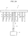
- FIG. 2A is a configuration diagram (front view) of the rinse mechanism 12 used for the automatic analyzing device 100A according to the first embodiment of the present invention.
- the rinse mechanism 12 includes an arm 12a, suction nozzles S1 to S6 and S9, discharge nozzles D1 to D5 and D7, a supporting unit 12b, a syringe pump SP, and the like.
- the suction nozzle S1 and the discharge nozzle D1 are disposed adjacent to each other on the arm 12a.
- the suction nozzles S2 to S5 and the discharge nozzles D2 to D5 are similarly disposed on the arm 12a.
- the suction nozzles S suction a liquid such as the reaction liquid and the rinse water from the reaction cuvettes 3 by the syringe pump.
- the discharge nozzles D discharge a liquid such as the rinse water and the detergent to the reaction cuvettes 3 by the syringe pump.
- the diameters of the suction nozzles S1 to S8 and the discharge nozzles D1 to D7 are substantially the same, but the diameter of the suction nozzle S9 9 is larger. The reason is to completely suction the rinse water left in the reaction cuvettes 3. However, instead of making the diameter of the suction nozzle S9 larger, an attachment with a larger diameter may be attached. Details of an operation of the rinse mechanism 12 will be described later using FIG. 4 .
- FIG. 2B is a configuration diagram (top view) of the rinse mechanism 12 used for the automatic analyzing device 100A according to the first embodiment of the present invention.
- the arm 12a is substantially one-quarter ring-shaped.
- the suction nozzles S (S1 to S9) and the discharge nozzles D (D1 to D7) are disposed in an arc-shape on the lower surface of the arm 12a.
- a set of the suction nozzle S1 and the discharge nozzle D1, a set of the suction nozzle S2 and the discharge nozzle D2, a set of the suction nozzle S3 and the discharge nozzle D3, a set of the suction nozzle S4 and the discharge nozzle D4, a set of the suction nozzle S5 and the discharge nozzle D5, the suction nozzle S6, the discharge nozzle D7, the suction nozzle S8, and the suction nozzle S9 are disposed at a certain distance in a circumferential direction.
- Rotation of the reaction disk 4 is controlled such that the reaction cuvettes 3 which have completed a measurement are positioned below the suction nozzles S and the discharge nozzles D (in the direction of z (-)).
- the supporting unit 12b is fixed in the center of the arm 12a in the circumferential direction.
- FIG. 3 is a diagram that describes the function of the control device 20 used for the automatic analyzing device 100A according to the embodiment of the present invention.
- the control device 20 includes a processor 201 and a storage unit 202 (hard disk, memory, and the like).
- the processor 201 functions as a counting unit 201a, a determining unit 201b, and a control unit 201c.
- the counting unit 201a counts and stores in the storage unit 202 the use frequency of each reaction cuvette 3 for a specific reagent item based on the identification code of the reagent bottles 6, read by the code reader 11.
- the determining unit 201b determines whether the use frequency of each reaction cuvette 3 for the specific reagent item exceeds a predetermined threshold.
- the control unit 201c controls the R1 reagent pipetting mechanism 8 so as to soak with the special detergent only for a period derived by multiplying a pipetting cycle time, which indicates a period when a sample is pipetted, by the total number of reaction cuvettes and a predetermined integer.
- the predetermined threshold can be input from an input device (keyboard, mouse, and the like) connected to the control device 20.
- the predetermined threshold is equal to or greater than two.
- FIG. 4 is a diagram that describes the operation of the automatic analyzing device 100A according to the first embodiment of the present invention.
- FIG. 5 is an example of a time chart that describes the operation of the automatic analyzing device 100A according to the first embodiment of the present invention.
- consecutive numbers No. 1, No. 2, (7) are assigned to a plurality of reaction cuvettes 3 arranged on the reaction disk 4 in a circumferential direction (for example, clockwise).
- FIG. 5 a rinsing operation in a No. 1 reaction cuvette 3 will be described using FIG. 5 .
- the normal rinsing operation is carried out in the first to ninth cycles.
- the frequency of measurement for the specific reagent item does not exceed the predetermined threshold. Therefore, in a 10th cycle, the sample pipetting mechanism 5 suctions the sample from the sample containers 1 retained in the sample disk 2, and pipettes the sample suctioned to the No. 1 reaction cuvette 3.
- the R1 reagent pipetting mechanism 8 suctions a reagent R1 from the reagent bottles 6 for the first reagent and pipettes (adds) the reagent R1 suctioned to the No. 1 reaction cuvette 3.
- the R1 stirring mechanism 13 stirs the reaction liquid in the No. 1 reaction cuvette.
- the R2/3 reagent pipetting mechanism 9 suctions a reagent R2 from the reagent bottles 6 for a second reagent and pipettes the reagent R2 suctioned to the No. 1 reaction cuvette 3.
- the R2/3 stirring mechanism 14 stirs the reaction liquid in the No. 1 reaction cuvette.
- the photometry part 10 completes photometry of light transmitted through the No. 1 reaction cuvette 3.
- the frequency of measurement for the specific reagent item exceeds the predetermined threshold. Therefore, in the 12th cycle, the R1 reagent pipetting mechanism 8 suctions the special detergent retained in the reagent disk 7 and discharges the special detergent to the No. 2 reaction cuvette 3.
- the R1 stirring mechanism 13 stirs the special detergent in the No. 2 reaction cuvette.
- an interval, at which the sample is pipetted is 169 cycles.
- the next sample can be pipetted in a 179th cycle.
- the time for soaking with the special detergent is the time from a cycle when the detergent is discharged to a cycle when soaking is completed.
- the time for soaking with the special detergent is the time from the 12th cycle to the 170th cycle. That is, the time for soaking with the special detergent is 159 cycles, and pipetting cycle ⁇ total number of reaction cuvettes - (rinse cycle + free cycle) of the automatic analyzing device 100A.
- the number of reaction cuvettes is 169
- pipetting cycle is 3.6 seconds
- rinse cycle is nine
- the time for soaking with the special detergent may be pipetting cycle x total number of reaction cuvettes ⁇ integer - (rinse cycle + free cycle) of the automatic analyzing device 100A.
- the rinse and free cycles differ for each automatic analyzing device. Therefore, the time for soaking with the special detergent is represented as pipetting cycle ⁇ total number of reaction cuvettes ⁇ an integer INT1 - an integer INT2 .
- the time for soaking with the special detergent is set equal to or less than a value derived from pipetting cycle ⁇ total number of reaction cuvettes ⁇ integer.
- the time for soaking with the special detergent may be designated by inputting an integer used in this formula from the input device.
- an integer means an integer equal to or greater than 1.
- a lower limit is preferably 10 times or more the pipetting cycle. Therefore, it is preferable that the control unit 201c control the detergent feeding mechanism such that reaction cuvettes, which have exceeded the predetermined threshold, are soaked with the special detergent for a period 10 times or longer the pipetting cycle time.
- the time before the next sample is pipetted after the normal rinsing is carried out, following the special rinsing can be shortened.
- a decrease in analytical throughput can be suppressed.
- a carry-over attributable to stains accumulated with the frequency or hour of use by the special rinsing can be prevented.
- FIGS. 6 and 7 a configuration and an operation of an automatic analyzing device 100B according to a second embodiment of the present invention will be described using FIGS. 6 and 7 .
- FIG. 6 is a configuration diagram of the automatic analyzing device 100B according to the second embodiment of the present invention.
- sections identical to those in FIG. 1 bear identical signs.
- the automatic analyzing device 100B includes a nozzle 15 dedicated for a special detergent.
- the special detergent is disposed at a place other than a reagent disk 7.
- a tank for storing the special detergent may be provided, for example, near the nozzle 15 dedicated for a special detergent.
- FIG. 7 is an example of a time chart that describes the operation of the automatic analyzing device 100B according to the second embodiment of the present invention.
- a difference from FIG. 5 is timing for rinsing a No. 2 reaction cuvette 3 with the special detergent.
- the special detergent is, in a 13th cycle, discharged from the nozzle 15 dedicated for a special detergent into the No.2 reaction cuvette 3.
- the timing for discharging the special detergent by the nozzle 15 dedicated for a special detergent can be appropriately changed.
- a sample pipetting mechanism 5 may discharge a special detergent into reaction cuvettes 3.
- the special detergent is filled in similar containers to sample containers 1 and disposed in a sample disk 2.
- timing for discharging the special detergent by the sample pipetting mechanism 5 can be appropriately changed.
- an automatic analyzing device is assumed, where the sample containers 1 are disposed in the sample disk 2.
- the special detergent is disposed in the rack.
- a counting unit 201a counts and stores in a storage unit 202 a use frequency of each reaction cuvette 3 for a specific reagent item.
- the use frequency stored in the storage unit 202 may be reset.
- a count is reset even when the use frequency of each reaction cuvette for the specific reagent item is equal to or below a threshold.
- a plurality of thresholds of a use frequency for a specific reagent item which serves as a criterion to determine whether to carry out rinsing with a special detergent, may be provided. For example, in a case where two thresholds are set at N1 and N2 (N1 ⁇ N2), when the use frequency exceeds N1, a special rinsing is not carried out for reaction cuvettes, the use frequency of which exceeds N1, during a measurement. After the measurement, when there is not a request for a new measurement, the special rinsing will be carried out.
- the special rinsing is not carried out, and a measurement is made in response to the request for the new measurement, using the reaction cuvettes, the use frequency of which has exceeded N1.
- the special rinsing is carried out with the special detergent and the new measurement is not assigned even when there is a request for the new measurement after the measurement.
- a frequency of rinsing with a special detergent for each reaction cuvette 3 may be stored and displayed on a display device. Timing for exchanging reaction cuvettes and a threshold for the timing for the exchange may be made changeable at the input device via a screen displayed on a display device.
- a total use frequency of a specific reagent item may be stored and made a threshold.
- the present invention is not limited to the embodiments described above, but includes a variety of modifications.
- the embodiments described above have been described in detail in order to describe the prevent invention clearly, and are not necessarily limited to those including all of the configurations that have been described.
- a part of a configuration in an embodiment can be replaced with a configuration in another embodiment, and a configuration of another embodiment can also be added to a configuration of an embodiment.
- other configurations can be added, deleted, or substituted.
Landscapes
- Chemical & Material Sciences (AREA)
- General Health & Medical Sciences (AREA)
- Life Sciences & Earth Sciences (AREA)
- Health & Medical Sciences (AREA)
- Analytical Chemistry (AREA)
- Biochemistry (AREA)
- Physics & Mathematics (AREA)
- General Physics & Mathematics (AREA)
- Immunology (AREA)
- Pathology (AREA)
- Chemical Kinetics & Catalysis (AREA)
- General Chemical & Material Sciences (AREA)
- Automatic Analysis And Handling Materials Therefor (AREA)
Abstract
Description
- The present invention relates to an automatic analyzing device for making qualitative and quantitative analyses of biogenic substances such as blood and urine, and particularly relates to an automatic analyzing device for analyzing reaction cuvettes arranged on a circumference of a reaction disk while moving them in a circumferential direction.
- An automatic analyzing device is a device for measuring a reaction between a sample and a reagent by a means such as a photometer, and measuring components contained in the sample. The automatic analyzing device pipettes a sample such as blood, urine, and cerebrospinal fluid from a sample tube or a dedicated container into a reaction cuvette, pipettes a reagent from a reagent bottle into the reaction cuvette, and mixes the sample and the reagent.
- In an automatic analyzing device including a disk-shaped reaction disk, reaction cuvettes are arranged in a circumferential direction of the reaction disk. Here, when a specific reagent item easy to stain a reaction cuvette is repeatedly used for a specific reaction cuvette, the reaction cuvette may be stained significantly. In this case, the reaction cuvette becomes unavailable during analytical operation, and analytical throughput decreases.
- In the related art, in order to prevent a decrease in analytical throughput attributable to such a significant stain, when a specific reagent item easy to stain a reaction cuvette has been measured, each time after the measurement, the reaction cuvette is rinsed by filling and retaining therein a special detergent for a certain period of time.
- In this context, an automatic analyzing device capable of preventing, for each object to be rinsed, a carry-over (carrying over a sample or a reagent to the next analysis) attributable to stains accumulated with a frequency or an hour of use is known (for example, see PTL 1).
- PTL 1:
JP 2011-112502 A - In an automatic analyzing device as described in
PTL 1, reaction cuvettes are rinsed with a predetermined detergent when the frequency or hour of use exceeds a predetermined value. - However, there have been problems that all of the reaction cuvettes become unavailable every time they are rinsed with the predetermined detergent, and that analytical throughput decreases.
- An object of the present invention is to provide an automatic analyzing device capable of suppressing a decrease in analytical throughput, while preventing a carry-over attributable to stains accumulated with the frequency or hour of use.
- In order to achieve the object described above, the present invention includes a retaining mechanism that retains a plurality of reaction cuvettes, a rinse mechanism that rinses the reaction cuvettes with a first detergent and a second detergent, a detergent feeding mechanism that feeds a third detergent to the reaction cuvettes that have been rinsed by the rinse mechanism, a storage unit that stores a use frequency of each reaction cuvette for a specific reagent item, a counting unit that counts and stores in the storage unit the use frequency of each reaction cuvette for the specific reagent item, a determining unit that determines whether the counted use frequency has exceeded a predetermined threshold N1, and a control unit that controls the detergent feeding mechanism such that, in a case where the counted use frequency exceeds the predetermined threshold N1, the reaction cuvettes, which have exceeded the predetermined threshold N1, are soaked with the third detergent only for a period of time equal to or less than a value derived by multiplying a pipetting cycle time, which indicates a period when a sample is pipetted, by the total number of reaction cuvettes and a predetermined integer.
- According to the present invention, a decrease in analytical throughput can be suppressed while preventing a carry-over attributable to stains accumulated with the frequency or hour of use. Problems, configurations, and advantageous effects other than those described above will become apparent by the descriptions of the following embodiments.
-
- [
FIG. 1] FIG. 1 is a configuration diagram of an automatic analyzing device according to a first embodiment of the present invention. - [
FIG. 2A] FIG. 2A is a configuration diagram (front view) of a rinse mechanism used for the automatic analyzing device according to the first embodiment of the present invention. - [
FIG. 2B] FIG. 2B is a configuration diagram (top view) of the rinse mechanism used for the automatic analyzing device according to the first embodiment of the present invention. - [
FIG.3] FIG. 3 is a diagram that describes a function of a control device used for the automatic analyzing device according to the first embodiment of the present invention. - [
FIG. 4] FIG. 4 is a diagram that describes an operation of the automatic analyzing device according to the first embodiment of the present invention. - [
FIG. 5] FIG. 5 is an example of a time chart that describes the operation of the automatic analyzing device according to the first embodiment of the present invention. - [
FIG. 6] FIG. 6 is a configuration diagram of an automatic analyzing device according to a second embodiment of the present invention. - [
FIG. 7] FIG. 7 is an example of a time chart that describes an operation of the automatic analyzing device according to the second embodiment of the present invention. - A configuration and an operation of an
automatic analyzing device 100A according to a first embodiment of the present invention will be described below usingFIGS. 1 to 5 . - First, an overall configuration of the
automatic analyzing device 100A according to the first embodiment of the present invention will be described usingFIG. 1. FIG. 1 is a configuration diagram of theautomatic analyzing device 100A according to the first embodiment of the present invention. - The
automatic analyzing device 100A mainly includes asample disk 2, areaction disk 4, asample pipetting mechanism 5, areagent disk 7, an R1reagent pipetting mechanism 8, an R2/3reagent pipetting mechanism 9, aphotometry part 10, acode reader 11, and arinse mechanism 12. - The
sample disk 2 retains a plurality ofsample containers 1 that has contained a sample to be analyzed. Thereaction disk 4 retains a plurality ofreaction cuvettes 3 for carrying out a reaction and photometry. Thesample disk 2 and thereaction disk 4 are rotatable and disk-shaped. - The
sample pipetting mechanism 5 suctions the sample from thesample containers 1 retained in thesample disk 2, and pipettes the sample suctioned to thereaction cuvettes 3 retained in thereaction disk 4. - The
reagent disk 7 stores and cools a plurality ofreagent bottles 6. Eachreagent bottle 6 is filled with a first, second, or third reagent that is mixed with the sample and induces a reaction. Thereagent disk 7 is rotatable and disk-shaped. - In the present embodiment, a special detergent for rinsing the
reaction cuvettes 6 is also filled in thereagent bottles 6, which are disposed in thereagent disk 7. Here, as the special detergent, a plurality of types of detergents different in rinsing effects (acid and alkaline strength) can be set. In the present embodiment, an acid-based detergent (pH = 2 to 3, or lower) and an alkali-based detergent (pH = 12 to 14, or higher) are used as the special detergent. - The R1
reagent pipetting mechanism 8 pipettes the reagent from thereagent bottles 6 for the first reagent to thereaction cuvettes 3 retained in thereaction disk 4. The R1reagent pipetting mechanism 8 discharges the special detergent to thereaction cuvettes 3 at a predetermined timing and carries out rinsing. Details of a rinsing operation using the special detergent will be described later usingFIGS. 4 and5 . - The R2/3
reagent pipetting mechanism 9 pipettes the reagent from thereagent bottles 6 for the second or third reagent to thereaction cuvettes 3 retained in thereaction disk 4. Thephotometry part 10 carries out photometry of light transmitted through thereaction cuvettes 3. Thecode reader 11 reads an identification code provided to thereagent bottles 6. - The
rinse mechanism 12 includes a discharge nozzle that discharges rinse water and the detergent, a suction nozzle that suctions, for example, a reaction liquid, and the like. Therinse mechanism 12 rinses thereaction cuvettes 3 with the rinse water and the detergent. Details of a configuration of therinse mechanism 12 will be described later usingFIGS. 2A and2B . - An
R1 stirring mechanism 13 stirs a mixture of the sample and the reagent that are reacting in thereaction cuvettes 3 on thereaction disk 4. An R2/3stirring mechanism 14 has a similar function. - A
control device 20 includes a computer and the like, and controls an operation of each table (sample disk 2,reaction disk 4, reagent disk 7) and each mechanism (sample pipetting mechanism 5, R1reagent pipetting mechanism 8, and the like). - The
reaction disk 4, therinse mechanism 12, and the R1reagent pipetting mechanism 8 correspond to a retaining mechanism, the rinse mechanism, and a detergent feeding mechanism, respectively. - Next, a configuration of the
rinse mechanism 12 used for theautomatic analyzing device 100A according to the first embodiment of the present invention will be described usingFIG. 2A. FIG. 2A is a configuration diagram (front view) of the rinsemechanism 12 used for theautomatic analyzing device 100A according to the first embodiment of the present invention. - The rinse
mechanism 12 includes anarm 12a, suction nozzles S1 to S6 and S9, discharge nozzles D1 to D5 and D7, a supportingunit 12b, a syringe pump SP, and the like. - The suction nozzle S1 and the discharge nozzle D1 are disposed adjacent to each other on the
arm 12a. The suction nozzles S2 to S5 and the discharge nozzles D2 to D5 are similarly disposed on thearm 12a. - The suction nozzles S (S1 to S9) suction a liquid such as the reaction liquid and the rinse water from the
reaction cuvettes 3 by the syringe pump. The discharge nozzles D (D1 to D7) discharge a liquid such as the rinse water and the detergent to thereaction cuvettes 3 by the syringe pump. - The diameters of the suction nozzles S1 to S8 and the discharge nozzles D1 to D7 are substantially the same, but the diameter of the
suction nozzle S9 9 is larger. The reason is to completely suction the rinse water left in thereaction cuvettes 3. However, instead of making the diameter of the suction nozzle S9 larger, an attachment with a larger diameter may be attached. Details of an operation of the rinsemechanism 12 will be described later usingFIG. 4 . - Next, the configuration of the rinse
mechanism 12 used for theautomatic analyzing device 100A according to the first embodiment of the present invention will be described usingFIG. 2B. FIG. 2B is a configuration diagram (top view) of the rinsemechanism 12 used for theautomatic analyzing device 100A according to the first embodiment of the present invention. - The
arm 12a is substantially one-quarter ring-shaped. The suction nozzles S (S1 to S9) and the discharge nozzles D (D1 to D7) are disposed in an arc-shape on the lower surface of thearm 12a. - Specifically, a set of the suction nozzle S1 and the discharge nozzle D1, a set of the suction nozzle S2 and the discharge nozzle D2, a set of the suction nozzle S3 and the discharge nozzle D3, a set of the suction nozzle S4 and the discharge nozzle D4, a set of the suction nozzle S5 and the discharge nozzle D5, the suction nozzle S6, the discharge nozzle D7, the suction nozzle S8, and the suction nozzle S9 are disposed at a certain distance in a circumferential direction.
- Rotation of the
reaction disk 4 is controlled such that thereaction cuvettes 3 which have completed a measurement are positioned below the suction nozzles S and the discharge nozzles D (in the direction of z (-)). The supportingunit 12b is fixed in the center of thearm 12a in the circumferential direction. - Next, a function of the
control device 20 used for theautomatic analyzing device 100A according to the first embodiment of the present invention will be described usingFIG. 3. FIG. 3 is a diagram that describes the function of thecontrol device 20 used for theautomatic analyzing device 100A according to the embodiment of the present invention. - The
control device 20 includes aprocessor 201 and a storage unit 202 (hard disk, memory, and the like). Theprocessor 201 functions as acounting unit 201a, a determiningunit 201b, and acontrol unit 201c. - Specifically, the
counting unit 201a counts and stores in thestorage unit 202 the use frequency of eachreaction cuvette 3 for a specific reagent item based on the identification code of thereagent bottles 6, read by thecode reader 11. The determiningunit 201b determines whether the use frequency of eachreaction cuvette 3 for the specific reagent item exceeds a predetermined threshold. - In a case where the counted use frequency exceeds the predetermined threshold, the
control unit 201c controls the R1reagent pipetting mechanism 8 so as to soak with the special detergent only for a period derived by multiplying a pipetting cycle time, which indicates a period when a sample is pipetted, by the total number of reaction cuvettes and a predetermined integer. The predetermined threshold can be input from an input device (keyboard, mouse, and the like) connected to thecontrol device 20. The predetermined threshold is equal to or greater than two. - Next, an operation of the
automatic analyzing device 100A according to the first embodiment of the present invention will be described usingFIG. 4. FIG. 4 is a diagram that describes the operation of theautomatic analyzing device 100A according to the first embodiment of the present invention. - First, the operation of the rinse
mechanism 12 will be described for each pipetting cycle time, which indicates a period when the liquid (rinse water, detergent, and the like) is pipetted into the reaction cuvettes. -
- (1) In a first cycle, the rinse
mechanism 12 suctions the reaction liquid from thereaction cuvettes 3 by the suction nozzle S1. Next, the rinsemechanism 12 discharges the rinse water into thereaction cuvettes 3 by the discharge nozzle D1. The rinse water is deionized water (ion-exchange water). - (2) In a second cycle, the rinse
mechanism 12 suctions the rinse water from thereaction cuvettes 3 by the suction nozzle S1. Next, the rinsemechanism 12 discharges adetergent 1 into thereaction cuvettes 3 by the discharge nozzle D2. Thedetergent 1 is an alkali-based detergent. - (3) In a third cycle, the rinse
mechanism 12 suctions thedetergent 1 from thereaction cuvettes 3 by the suction nozzle S3. Next, the rinsemechanism 12 discharges adetergent 2 into thereaction cuvettes 3 by the discharge nozzle D3. Thedetergent 2 is an acid-based detergent. - (4) In a fourth cycle, the rinse
mechanism 12 suctions thedetergent 2 from thereaction cuvettes 3 by the suction nozzle S4. Next, the rinsemechanism 12 discharges the rinse water into thereaction cuvettes 3 by the discharge nozzle D4. - (5) In a fifth cycle, the rinse
mechanism 12 suctions the rinse water from thereaction cuvettes 3 by the suction nozzle S5. Next, the rinsemechanism 12 discharges the rinse water by the discharge nozzle D5. - (6) In a sixth cycle, the rinse
mechanism 12 suctions the rinse water from thereaction cuvettes 3 by the suction nozzle S6. - (7) In a seventh cycle, the rinse
mechanism 12 discharges blank water by the discharge nozzle D7. The blank water is deionized water (ion-exchange water). The blank water is used to keep a condition obtained by rinsing with thedetergents reaction cuvettes 3 in the seventh cycle is less than that of the rinse water discharged into thereaction cuvettes 3 in other cycles. - (8) In an eighth cycle, the rinse
mechanism 12 suctions the blank water from thereaction cuvettes 3 by the suction nozzle S8. - (9) In a ninth cycle, the rinse
mechanism 12 suctions the blank water from thereaction cuvettes 3 by the suction nozzle S9. In the eighth and ninth cycles, the blank water is continuously suctioned from thereaction cuvettes 3. Thus, the blank water in thereaction cuvettes 3 is almost completely suctioned. - As described in (1) to (9) above, a normal rinsing operation is completed. Next, a special rinsing operation by the R1
reagent pipetting mechanism 8 and the like will be described. - (J) When the normal rinsing operation is completed, the
control device 20 determines, for thereaction cuvettes 3 which have completed rinsing by the rinsemechanism 12, whether the frequency of measurement for the specific reagent item (such as hemoglobin A1c (HbA1c) difficult to remove) exceeds a predetermined threshold.
When the frequency of measurement does not exceed the predetermined threshold, thecontrol device 20 finishes rinsing of thereaction cuvettes 3. Then, thereaction cuvettes 3 that have completed rinsing are used for the next measurement.
On the other hand, when the frequency of measurement exceeds the predetermined threshold, thecontrol device 20 carries out, as described below, a special rinsing operation. - (K) When the frequency of measurement exceeds the predetermined threshold, the R1
reagent pipetting mechanism 8 suctions the special detergent retained in thereagent disk 7 and discharges the special detergent into thereaction cuvettes 3. In the present embodiment, the R1reagent pipetting mechanism 8 suctions and discharges the special detergent. However, the R2/3reagent pipetting mechanism 9 may suction and discharge the special detergent. - (L) The
R1 stirring mechanism 13 stirs the special detergent in the reaction cuvettes. As a result, the rinsing effect increases. - (M) Then, the
reaction cuvettes 3 are soaked with the special detergent for a certain period of time. The time for soaking with the special detergent is, in (1) to (9), longer than the time for the rinsemechanism 12 to rinse thereaction cuvettes 3. Although not always required, it is preferable, as described above, to stir the special detergent while the reaction cuvettes are soaked with the special detergent. - Next, the operation of the
automatic analyzing device 100A according to the first embodiment of the present invention will be described usingFIG. 5. FIG. 5 is an example of a time chart that describes the operation of theautomatic analyzing device 100A according to the first embodiment of the present invention. For ease of description, consecutive numbers (No. 1, No. 2, ...) are assigned to a plurality ofreaction cuvettes 3 arranged on thereaction disk 4 in a circumferential direction (for example, clockwise). - A rinsing operation in a case where the frequency of measurement for the specific reagent item (for example, HbA1c) exceeds the predetermined threshold at a No. 2
reaction cuvette 3, and does not exceed the predetermined threshold at the other reaction cuvettes will be described below as an example. - First, a rinsing operation in a No. 1
reaction cuvette 3 will be described usingFIG. 5 . As described usingFIG. 4 , the normal rinsing operation is carried out in the first to ninth cycles. - Here, in the No. 1
reaction cuvette 3, the frequency of measurement for the specific reagent item does not exceed the predetermined threshold. Therefore, in a 10th cycle, thesample pipetting mechanism 5 suctions the sample from thesample containers 1 retained in thesample disk 2, and pipettes the sample suctioned to the No. 1reaction cuvette 3. - In an 11th cycle, the R1
reagent pipetting mechanism 8 suctions a reagent R1 from thereagent bottles 6 for the first reagent and pipettes (adds) the reagent R1 suctioned to the No. 1reaction cuvette 3. - In a 12th cycle, the
R1 stirring mechanism 13 stirs the reaction liquid in the No. 1 reaction cuvette. - Then, in a 51st cycle, the R2/3
reagent pipetting mechanism 9 suctions a reagent R2 from thereagent bottles 6 for a second reagent and pipettes the reagent R2 suctioned to the No. 1reaction cuvette 3. - In a 52nd cycle, the R2/3
stirring mechanism 14 stirs the reaction liquid in the No. 1 reaction cuvette. - Then, in a 168th cycle, the
photometry part 10 completes photometry of light transmitted through the No. 1reaction cuvette 3. - In 170th to 178th cycles, processing in (1) to (9) is executed. Accordingly, the normal rinsing operation is completed.
- Next, a rinsing operation in a No. 2
reaction cuvette 3 will be described usingFIG. 5 . In the second to 10th cycles, a normal rinsing operation is carried out. The timing for initiating rinsing of the No. 2reaction cuvette 3 is one cycle behind compared with the No. 1reaction cuvette 3. - Here, in the No. 2
reaction cuvette 3, the frequency of measurement for the specific reagent item exceeds the predetermined threshold. Therefore, in the 12th cycle, the R1reagent pipetting mechanism 8 suctions the special detergent retained in thereagent disk 7 and discharges the special detergent to the No. 2reaction cuvette 3. - In a 13th cycle, the
R1 stirring mechanism 13 stirs the special detergent in the No. 2 reaction cuvette. - Then, in 14th to 170th cycles, the No. 2 reaction cuvette is soaked with the special detergent.
- In 171st to 178th cycles, the processing described in (1) to (9) is executed.
- In the present embodiment, as with the No. 1
reaction cuvette 3, when only the normal rinsing is carried out, an interval, at which the sample is pipetted, is 169 cycles. In an example ofFIG. 5 , after a sample is pipetted in the 10th cycle, the next sample can be pipetted in a 179th cycle. - On the other hand, as with the No. 2
reaction cuvette 3, when the special rising is carried out once, an interval, at which the sample is pipetted, is 169 + 169 = 169 × 2 cycles. Here, the time for soaking with the special detergent is the time from a cycle when the detergent is discharged to a cycle when soaking is completed. In the No. 2reaction cuvette 3 illustrated inFIG. 5 , the time for soaking with the special detergent is the time from the 12th cycle to the 170th cycle. That is, the time for soaking with the special detergent is 159 cycles, and pipetting cycle × total number of reaction cuvettes - (rinse cycle + free cycle) of theautomatic analyzing device 100A. In the present embodiment, the number of reaction cuvettes is 169, pipetting cycle is 3.6 seconds, rinse cycle is nine, and free cycle is one. Therefore, the time for soaking is 3.6 × 169 - (9 + 1) = 572.4 seconds. - The time for soaking with the special detergent may be pipetting cycle x total number of reaction cuvettes × integer - (rinse cycle + free cycle) of the
automatic analyzing device 100A. Here, the rinse and free cycles differ for each automatic analyzing device. Therefore, the time for soaking with the special detergent is represented as pipetting cycle × total number of reaction cuvettes × an integer INT1 - an integer INT2 . In other words, the time for soaking with the special detergent is set equal to or less than a value derived from pipetting cycle × total number of reaction cuvettes × integer. The time for soaking with the special detergent may be designated by inputting an integer used in this formula from the input device. Here, an integer means an integer equal to or greater than 1. On the other hand, a lower limit is preferably 10 times or more the pipetting cycle. Therefore, it is preferable that thecontrol unit 201c control the detergent feeding mechanism such that reaction cuvettes, which have exceeded the predetermined threshold, are soaked with the special detergent for aperiod 10 times or longer the pipetting cycle time. - As described above, according to the present embodiment, the time before the next sample is pipetted after the normal rinsing is carried out, following the special rinsing can be shortened. Thus, even when the special rinsing is carried out, a decrease in analytical throughput can be suppressed. In addition, a carry-over attributable to stains accumulated with the frequency or hour of use by the special rinsing can be prevented.
- Next, a configuration and an operation of an
automatic analyzing device 100B according to a second embodiment of the present invention will be described usingFIGS. 6 and7 . - First, an overall configuration of the
automatic analyzing device 100B according to the second embodiment of the present invention will be described usingFIG. 6. FIG. 6 is a configuration diagram of theautomatic analyzing device 100B according to the second embodiment of the present invention. InFIG. 6 , sections identical to those inFIG. 1 bear identical signs. - In
FIG. 6 , a difference fromFIG. 1 is that theautomatic analyzing device 100B includes anozzle 15 dedicated for a special detergent. In the present embodiment, the special detergent is disposed at a place other than areagent disk 7. Specifically, a tank for storing the special detergent may be provided, for example, near thenozzle 15 dedicated for a special detergent. - Next, an operation of the
automatic analyzing device 100B according to the second embodiment of the present invention will be described usingFIG. 7. FIG. 7 is an example of a time chart that describes the operation of theautomatic analyzing device 100B according to the second embodiment of the present invention. - In
FIG. 7 , a difference fromFIG. 5 is timing for rinsing a No. 2reaction cuvette 3 with the special detergent. Specifically, in the present embodiment, the special detergent is, in a 13th cycle, discharged from thenozzle 15 dedicated for a special detergent into the No.2reaction cuvette 3. - As described above, according to the present embodiment, the timing for discharging the special detergent by the
nozzle 15 dedicated for a special detergent can be appropriately changed. - A
sample pipetting mechanism 5 may discharge a special detergent intoreaction cuvettes 3. In this case, the special detergent is filled in similar containers to samplecontainers 1 and disposed in asample disk 2. - According to the present modification, timing for discharging the special detergent by the
sample pipetting mechanism 5 can be appropriately changed. - In the present modification, an automatic analyzing device is assumed, where the
sample containers 1 are disposed in thesample disk 2. However, in a case of an automatic analyzing device where thesample containers 1 are disposed in a rack, the special detergent is disposed in the rack. - In the first and second embodiments, a
counting unit 201a counts and stores in a storage unit 202 a use frequency of eachreaction cuvette 3 for a specific reagent item. Here, when predetermined operations are carried out, such as when thereaction cuvettes 3 are rinsed with the special detergent and when thereaction cuvettes 3 are exchanged, the use frequency stored in thestorage unit 202 may be reset. - After these predetermined operations are carried out, a count is reset even when the use frequency of each reaction cuvette for the specific reagent item is equal to or below a threshold.
- A plurality of thresholds of a use frequency for a specific reagent item, which serves as a criterion to determine whether to carry out rinsing with a special detergent, may be provided. For example, in a case where two thresholds are set at N1 and N2 (N1 < N2), when the use frequency exceeds N1, a special rinsing is not carried out for reaction cuvettes, the use frequency of which exceeds N1, during a measurement. After the measurement, when there is not a request for a new measurement, the special rinsing will be carried out. When there is a request for a new measurement after the measurement, the special rinsing is not carried out, and a measurement is made in response to the request for the new measurement, using the reaction cuvettes, the use frequency of which has exceeded N1. On the other hand, in a case where the use frequency has exceeded N2, for the reaction cuvettes, the use frequency of which has exceeded N2, the special rinsing is carried out with the special detergent and the new measurement is not assigned even when there is a request for the new measurement after the measurement.
- A frequency of rinsing with a special detergent for each
reaction cuvette 3 may be stored and displayed on a display device. Timing for exchanging reaction cuvettes and a threshold for the timing for the exchange may be made changeable at the input device via a screen displayed on a display device. - Instead of storing the frequency of rising with the special detergent, a total use frequency of a specific reagent item may be stored and made a threshold.
- The present invention is not limited to the embodiments described above, but includes a variety of modifications. For example, the embodiments described above have been described in detail in order to describe the prevent invention clearly, and are not necessarily limited to those including all of the configurations that have been described. A part of a configuration in an embodiment can be replaced with a configuration in another embodiment, and a configuration of another embodiment can also be added to a configuration of an embodiment. For a part of a configuration of each embodiment, other configurations can be added, deleted, or substituted.
-
- 1
- Sample container
- 2
- Sample disk
- 3
- Reaction cuvette
- 4
- Reaction disk
- 5
- Sample pipetting mechanism
- 6
- Reagent bottle
- 7
- Reagent disk
- 8
- R1 reagent pipetting mechanism
- 9
- R2/3 reagent pipetting mechanism
- 10
- Photometry part
- 11
- Code reader
- 12
- Rinse mechanism
- 13
- R1 stirring mechanism
- 14
- R2/3 stirring mechanism
- 15
- Nozzle dedicated for special detergent
- 20
- Control device
- 201
- Processor
- 201a
- Counting unit
- 201b
- Determining unit
- 201c
- Control unit
- 202
- Storage unit
- 100A, 100B
- Automatic analyzing device
Claims (7)
- An automatic analyzing device comprising:a retaining mechanism that retains a plurality of reaction cuvettes;a rinse mechanism that rinses the reaction cuvettes with a first detergent and a second detergent;a detergent feeding mechanism that feeds a third detergent to the reaction cuvettes that have been rinsed by the rinse mechanism;a storage unit that stores a use frequency of each reaction cuvette for a specific reagent item;a counting unit that counts and stores in the storage unit the use frequency of each reaction cuvette for the specific reagent item;a determining unit that determines whether the counted use frequency has exceeded a predetermined threshold N1; anda control unit that controls the detergent feeding mechanism such that, in a case where the counted use frequency exceeds the predetermined threshold N1, the reaction cuvettes, which have exceeded the predetermined threshold N1, are soaked with the third detergent only for a period of time equal to or less than a value derived by multiplying a pipetting cycle time, which indicates a period when a sample is pipetted, by the total number of reaction cuvettes and a predetermined integer.
- The automatic analyzing device according to claim 1, wherein the control unit controls the detergent feeding mechanism such that:in a case where the counted use frequency exceeds the predetermined threshold N1, the reaction cuvettes, which have exceeded the predetermined threshold N1, are not soaked during measurement, and the reaction cuvettes that have exceeded the predetermined threshold N1 are soaked when there is not a request for a new measurement after the reaction cuvettes that have exceeded the predetermined threshold N1 are measured; andin a case where the counted use frequency exceeds a predetermined threshold N2, which is larger than the predetermined threshold N1, the reaction cuvettes, which have exceeded the predetermined threshold N2, are soaked without assigning a new measurement to the reaction cuvettes that have exceeded the predetermined threshold N2, even when there is a request for a new measurement.
- The automatic analyzing device according to claim 1, wherein the detergent feeding mechanism comprises a nozzle dedicated for the third detergent, provided separately from a reagent pipetting mechanism configured to pipette a reagent from reagent bottles to the reaction cuvettes and a sample pipetting mechanism configured to pipette a sample from sample containers to the reaction cuvettes.
- The automatic analyzing device according to claim 1, wherein the retaining mechanism is a rotatable disk-shaped reaction disk.
- The automatic analyzing device according to claim 1, wherein the threshold N1 is equal to or greater than 2.
- The automatic analyzing device according to claim 1, wherein the control unit controls the detergent mechanism such that the reaction cuvettes, which have exceeded the predetermined threshold N1, are soaked with the third detergent for a period 10 times or longer the pipetting cycle time.
- The automatic analyzing device according to claim 1, wherein the third detergent is stirred while the reaction cuvettes, which have exceeded the predetermined threshold N1, are soaked with the third detergent.
Applications Claiming Priority (2)
| Application Number | Priority Date | Filing Date | Title |
|---|---|---|---|
| JP2013087413 | 2013-04-18 | ||
| PCT/JP2014/059889 WO2014171346A1 (en) | 2013-04-18 | 2014-04-03 | Automatic analysis device |
Publications (3)
| Publication Number | Publication Date |
|---|---|
| EP2988133A1 true EP2988133A1 (en) | 2016-02-24 |
| EP2988133A4 EP2988133A4 (en) | 2016-11-16 |
| EP2988133B1 EP2988133B1 (en) | 2020-01-22 |
Family
ID=51731293
Family Applications (1)
| Application Number | Title | Priority Date | Filing Date |
|---|---|---|---|
| EP14785965.6A Active EP2988133B1 (en) | 2013-04-18 | 2014-04-03 | Automatic analysis device |
Country Status (5)
| Country | Link |
|---|---|
| US (2) | US9933447B2 (en) |
| EP (1) | EP2988133B1 (en) |
| JP (1) | JP6373260B2 (en) |
| CN (1) | CN105122069B (en) |
| WO (1) | WO2014171346A1 (en) |
Cited By (2)
| Publication number | Priority date | Publication date | Assignee | Title |
|---|---|---|---|---|
| JP2017096761A (en) * | 2015-11-24 | 2017-06-01 | 東芝メディカルシステムズ株式会社 | Automatic analyzer |
| AT527701A1 (en) * | 2023-11-10 | 2025-05-15 | Meon Medical Solutions Gmbh & Co Kg | PROCEDURE FOR PREPARING A CUVETTE |
Families Citing this family (11)
| Publication number | Priority date | Publication date | Assignee | Title |
|---|---|---|---|---|
| JP6355960B2 (en) * | 2014-04-28 | 2018-07-11 | キヤノンメディカルシステムズ株式会社 | CLINICAL INSPECTION DEVICE AND CONTAINER CLEANING METHOD |
| JP6504944B2 (en) * | 2015-07-10 | 2019-04-24 | 株式会社日立ハイテクノロジーズ | Automatic analyzer |
| CN107643410B (en) * | 2016-07-21 | 2021-04-02 | 深圳迈瑞生物医疗电子股份有限公司 | Sample analyzer and cleaning control method for sample analyzer |
| CN110383074B (en) * | 2017-01-23 | 2024-02-20 | 株式会社日立高新技术 | automatic analysis device |
| EP3696551B1 (en) | 2017-10-12 | 2024-02-14 | Hitachi High-Tech Corporation | Automated analyzer |
| EP3732491B1 (en) * | 2017-12-29 | 2024-11-06 | Beckman Coulter, Inc. | Sample analysis system comprising a probe washing arrangement and method of using it |
| JP7118646B2 (en) * | 2018-01-12 | 2022-08-16 | キヤノンメディカルシステムズ株式会社 | Automatic analyzer and cleaning method |
| CN112444467B (en) * | 2019-09-05 | 2024-08-13 | 深圳迈瑞动物医疗科技股份有限公司 | Cleaning method, blood cell analyzer and storage medium |
| CN115524504B (en) * | 2021-06-25 | 2025-02-18 | 深圳市帝迈生物技术有限公司 | Sample analysis device, cleaning method thereof and computer readable storage medium |
| CN115541900B (en) * | 2021-06-30 | 2026-04-03 | 深圳市帝迈生物技术有限公司 | A blood analyzer and its detection method |
| CN114345859B (en) * | 2021-12-29 | 2023-01-20 | 海南医学院 | Clinical biochemistry inspection is with test tube vibration belt cleaning device |
Family Cites Families (13)
| Publication number | Priority date | Publication date | Assignee | Title |
|---|---|---|---|---|
| JP2510152B2 (en) | 1985-11-19 | 1996-06-26 | オリンパス光学工業株式会社 | Automatic analyzer |
| JP2661017B2 (en) * | 1986-07-28 | 1997-10-08 | 株式会社島津製作所 | Automatic analyzer |
| JPH0634932B2 (en) | 1987-04-06 | 1994-05-11 | 日本テクトロン株式会社 | Temperature control structure for reagent bottle table |
| JPH07103984A (en) * | 1993-09-30 | 1995-04-21 | Shimadzu Corp | Automatic chemical analyzer |
| JPH10267939A (en) | 1997-03-24 | 1998-10-09 | Olympus Optical Co Ltd | Cleaning tank |
| JPH11258246A (en) | 1998-03-16 | 1999-09-24 | Olympus Optical Co Ltd | Autoanalyzer |
| JP2000065744A (en) * | 1998-08-25 | 2000-03-03 | Hitachi Ltd | Automatic analyzer |
| JP3901587B2 (en) | 2002-06-12 | 2007-04-04 | 株式会社東芝 | Automatic analyzer and data management method in automatic analyzer |
| US7687767B2 (en) * | 2002-12-20 | 2010-03-30 | Agilent Technologies, Inc. | Fast scanning stage for a scanning probe microscope |
| JP2004279289A (en) * | 2003-03-18 | 2004-10-07 | Hitachi High-Technologies Corp | Automatic analyzer |
| US20050272047A1 (en) | 2004-06-08 | 2005-12-08 | Arthur Schleifer | Automated process for washing array substrates |
| JP2011112502A (en) | 2009-11-26 | 2011-06-09 | Beckman Coulter Inc | Autoanalyzer and washing method |
| JP5836195B2 (en) | 2011-06-14 | 2015-12-24 | 日本電子株式会社 | Clinical laboratory analyzer and cleaning method in clinical laboratory analyzer |
-
2014
- 2014-04-03 WO PCT/JP2014/059889 patent/WO2014171346A1/en not_active Ceased
- 2014-04-03 JP JP2015512445A patent/JP6373260B2/en active Active
- 2014-04-03 CN CN201480021201.8A patent/CN105122069B/en active Active
- 2014-04-03 EP EP14785965.6A patent/EP2988133B1/en active Active
- 2014-04-03 US US14/784,359 patent/US9933447B2/en active Active
-
2018
- 2018-02-27 US US15/905,881 patent/US10422808B2/en active Active
Cited By (2)
| Publication number | Priority date | Publication date | Assignee | Title |
|---|---|---|---|---|
| JP2017096761A (en) * | 2015-11-24 | 2017-06-01 | 東芝メディカルシステムズ株式会社 | Automatic analyzer |
| AT527701A1 (en) * | 2023-11-10 | 2025-05-15 | Meon Medical Solutions Gmbh & Co Kg | PROCEDURE FOR PREPARING A CUVETTE |
Also Published As
| Publication number | Publication date |
|---|---|
| US20180180636A1 (en) | 2018-06-28 |
| CN105122069B (en) | 2017-09-01 |
| JPWO2014171346A1 (en) | 2017-02-23 |
| US10422808B2 (en) | 2019-09-24 |
| CN105122069A (en) | 2015-12-02 |
| EP2988133A4 (en) | 2016-11-16 |
| EP2988133B1 (en) | 2020-01-22 |
| US9933447B2 (en) | 2018-04-03 |
| WO2014171346A1 (en) | 2014-10-23 |
| US20160061852A1 (en) | 2016-03-03 |
| JP6373260B2 (en) | 2018-08-15 |
Similar Documents
| Publication | Publication Date | Title |
|---|---|---|
| US10422808B2 (en) | Automatic analyzing device | |
| CN104024867B (en) | Automatic analysing apparatus and sample dispensing probe cleaning method | |
| US9618526B2 (en) | Automated analyzer | |
| JP6660844B2 (en) | Automatic analyzer and program | |
| JP4528814B2 (en) | Automatic analyzer and method of operating automatic analyzer | |
| EP1538446A2 (en) | Automatic analyzer and analysis method | |
| EP3767301A1 (en) | Automatic analysis device | |
| JP6464026B2 (en) | Automatic analyzer | |
| JPWO2017163613A1 (en) | Automatic analyzer | |
| JP6995085B2 (en) | Automatic analyzer and control method of automated analyzer | |
| US20220341956A1 (en) | Automatic analyzer | |
| JP6504944B2 (en) | Automatic analyzer | |
| EP3410122B1 (en) | Automatic analyzer and program | |
| JP6340245B2 (en) | Automatic analyzer | |
| JP2019211329A (en) | Automatic analyzer | |
| JP6058277B2 (en) | Automatic analyzer | |
| JPWO2018230217A1 (en) | Automatic analyzer | |
| EP3859349B1 (en) | Test method and dispensing device | |
| JP7245644B2 (en) | Automatic analyzer and automatic analysis method | |
| JP6915010B2 (en) | Automatic analyzer and automatic analysis method | |
| RU2781440C1 (en) | Automatic analyzer | |
| JP7768728B2 (en) | Automated analysis device and method | |
| US20250076332A1 (en) | Automatic analyzing apparatus and method | |
| JP7118646B2 (en) | Automatic analyzer and cleaning method | |
| JP2009243995A (en) | Automatic analyzer |
Legal Events
| Date | Code | Title | Description |
|---|---|---|---|
| PUAI | Public reference made under article 153(3) epc to a published international application that has entered the european phase |
Free format text: ORIGINAL CODE: 0009012 |
|
| 17P | Request for examination filed |
Effective date: 20151111 |
|
| AK | Designated contracting states |
Kind code of ref document: A1 Designated state(s): AL AT BE BG CH CY CZ DE DK EE ES FI FR GB GR HR HU IE IS IT LI LT LU LV MC MK MT NL NO PL PT RO RS SE SI SK SM TR |
|
| AX | Request for extension of the european patent |
Extension state: BA ME |
|
| DAX | Request for extension of the european patent (deleted) | ||
| A4 | Supplementary search report drawn up and despatched |
Effective date: 20161014 |
|
| RIC1 | Information provided on ipc code assigned before grant |
Ipc: G01N 35/02 20060101AFI20161010BHEP |
|
| STAA | Information on the status of an ep patent application or granted ep patent |
Free format text: STATUS: EXAMINATION IS IN PROGRESS |
|
| 17Q | First examination report despatched |
Effective date: 20181204 |
|
| GRAP | Despatch of communication of intention to grant a patent |
Free format text: ORIGINAL CODE: EPIDOSNIGR1 |
|
| STAA | Information on the status of an ep patent application or granted ep patent |
Free format text: STATUS: GRANT OF PATENT IS INTENDED |
|
| INTG | Intention to grant announced |
Effective date: 20190930 |
|
| GRAS | Grant fee paid |
Free format text: ORIGINAL CODE: EPIDOSNIGR3 |
|
| GRAA | (expected) grant |
Free format text: ORIGINAL CODE: 0009210 |
|
| STAA | Information on the status of an ep patent application or granted ep patent |
Free format text: STATUS: THE PATENT HAS BEEN GRANTED |
|
| AK | Designated contracting states |
Kind code of ref document: B1 Designated state(s): AL AT BE BG CH CY CZ DE DK EE ES FI FR GB GR HR HU IE IS IT LI LT LU LV MC MK MT NL NO PL PT RO RS SE SI SK SM TR |
|
| REG | Reference to a national code |
Ref country code: GB Ref legal event code: FG4D |
|
| REG | Reference to a national code |
Ref country code: CH Ref legal event code: EP |
|
| REG | Reference to a national code |
Ref country code: AT Ref legal event code: REF Ref document number: 1227235 Country of ref document: AT Kind code of ref document: T Effective date: 20200215 |
|
| REG | Reference to a national code |
Ref country code: IE Ref legal event code: FG4D |
|
| REG | Reference to a national code |
Ref country code: DE Ref legal event code: R096 Ref document number: 602014060378 Country of ref document: DE |
|
| REG | Reference to a national code |
Ref country code: NL Ref legal event code: MP Effective date: 20200122 |
|
| RAP2 | Party data changed (patent owner data changed or rights of a patent transferred) |
Owner name: HITACHI HIGH-TECH CORPORATION |
|
| REG | Reference to a national code |
Ref country code: DE Ref legal event code: R082 Ref document number: 602014060378 Country of ref document: DE Representative=s name: STREHL SCHUEBEL-HOPF & PARTNER MBB PATENTANWAE, DE Ref country code: DE Ref legal event code: R081 Ref document number: 602014060378 Country of ref document: DE Owner name: HITACHI HIGH-TECH CORPORATION, JP Free format text: FORMER OWNER: HITACHI HIGH-TECHNOLOGIES CORPORATION, TOKYO, JP |
|
| REG | Reference to a national code |
Ref country code: LT Ref legal event code: MG4D |
|
| PG25 | Lapsed in a contracting state [announced via postgrant information from national office to epo] |
Ref country code: RS Free format text: LAPSE BECAUSE OF FAILURE TO SUBMIT A TRANSLATION OF THE DESCRIPTION OR TO PAY THE FEE WITHIN THE PRESCRIBED TIME-LIMIT Effective date: 20200122 Ref country code: NL Free format text: LAPSE BECAUSE OF FAILURE TO SUBMIT A TRANSLATION OF THE DESCRIPTION OR TO PAY THE FEE WITHIN THE PRESCRIBED TIME-LIMIT Effective date: 20200122 Ref country code: PT Free format text: LAPSE BECAUSE OF FAILURE TO SUBMIT A TRANSLATION OF THE DESCRIPTION OR TO PAY THE FEE WITHIN THE PRESCRIBED TIME-LIMIT Effective date: 20200614 Ref country code: FI Free format text: LAPSE BECAUSE OF FAILURE TO SUBMIT A TRANSLATION OF THE DESCRIPTION OR TO PAY THE FEE WITHIN THE PRESCRIBED TIME-LIMIT Effective date: 20200122 Ref country code: NO Free format text: LAPSE BECAUSE OF FAILURE TO SUBMIT A TRANSLATION OF THE DESCRIPTION OR TO PAY THE FEE WITHIN THE PRESCRIBED TIME-LIMIT Effective date: 20200422 |
|
| PG25 | Lapsed in a contracting state [announced via postgrant information from national office to epo] |
Ref country code: LV Free format text: LAPSE BECAUSE OF FAILURE TO SUBMIT A TRANSLATION OF THE DESCRIPTION OR TO PAY THE FEE WITHIN THE PRESCRIBED TIME-LIMIT Effective date: 20200122 Ref country code: SE Free format text: LAPSE BECAUSE OF FAILURE TO SUBMIT A TRANSLATION OF THE DESCRIPTION OR TO PAY THE FEE WITHIN THE PRESCRIBED TIME-LIMIT Effective date: 20200122 Ref country code: GR Free format text: LAPSE BECAUSE OF FAILURE TO SUBMIT A TRANSLATION OF THE DESCRIPTION OR TO PAY THE FEE WITHIN THE PRESCRIBED TIME-LIMIT Effective date: 20200423 Ref country code: BG Free format text: LAPSE BECAUSE OF FAILURE TO SUBMIT A TRANSLATION OF THE DESCRIPTION OR TO PAY THE FEE WITHIN THE PRESCRIBED TIME-LIMIT Effective date: 20200422 Ref country code: HR Free format text: LAPSE BECAUSE OF FAILURE TO SUBMIT A TRANSLATION OF THE DESCRIPTION OR TO PAY THE FEE WITHIN THE PRESCRIBED TIME-LIMIT Effective date: 20200122 Ref country code: IS Free format text: LAPSE BECAUSE OF FAILURE TO SUBMIT A TRANSLATION OF THE DESCRIPTION OR TO PAY THE FEE WITHIN THE PRESCRIBED TIME-LIMIT Effective date: 20200522 |
|
| REG | Reference to a national code |
Ref country code: DE Ref legal event code: R097 Ref document number: 602014060378 Country of ref document: DE |
|
| PG25 | Lapsed in a contracting state [announced via postgrant information from national office to epo] |
Ref country code: EE Free format text: LAPSE BECAUSE OF FAILURE TO SUBMIT A TRANSLATION OF THE DESCRIPTION OR TO PAY THE FEE WITHIN THE PRESCRIBED TIME-LIMIT Effective date: 20200122 Ref country code: SK Free format text: LAPSE BECAUSE OF FAILURE TO SUBMIT A TRANSLATION OF THE DESCRIPTION OR TO PAY THE FEE WITHIN THE PRESCRIBED TIME-LIMIT Effective date: 20200122 Ref country code: SM Free format text: LAPSE BECAUSE OF FAILURE TO SUBMIT A TRANSLATION OF THE DESCRIPTION OR TO PAY THE FEE WITHIN THE PRESCRIBED TIME-LIMIT Effective date: 20200122 Ref country code: DK Free format text: LAPSE BECAUSE OF FAILURE TO SUBMIT A TRANSLATION OF THE DESCRIPTION OR TO PAY THE FEE WITHIN THE PRESCRIBED TIME-LIMIT Effective date: 20200122 Ref country code: CZ Free format text: LAPSE BECAUSE OF FAILURE TO SUBMIT A TRANSLATION OF THE DESCRIPTION OR TO PAY THE FEE WITHIN THE PRESCRIBED TIME-LIMIT Effective date: 20200122 Ref country code: RO Free format text: LAPSE BECAUSE OF FAILURE TO SUBMIT A TRANSLATION OF THE DESCRIPTION OR TO PAY THE FEE WITHIN THE PRESCRIBED TIME-LIMIT Effective date: 20200122 Ref country code: ES Free format text: LAPSE BECAUSE OF FAILURE TO SUBMIT A TRANSLATION OF THE DESCRIPTION OR TO PAY THE FEE WITHIN THE PRESCRIBED TIME-LIMIT Effective date: 20200122 Ref country code: LT Free format text: LAPSE BECAUSE OF FAILURE TO SUBMIT A TRANSLATION OF THE DESCRIPTION OR TO PAY THE FEE WITHIN THE PRESCRIBED TIME-LIMIT Effective date: 20200122 |
|
| REG | Reference to a national code |
Ref country code: AT Ref legal event code: MK05 Ref document number: 1227235 Country of ref document: AT Kind code of ref document: T Effective date: 20200122 |
|
| PLBE | No opposition filed within time limit |
Free format text: ORIGINAL CODE: 0009261 |
|
| STAA | Information on the status of an ep patent application or granted ep patent |
Free format text: STATUS: NO OPPOSITION FILED WITHIN TIME LIMIT |
|
| PG25 | Lapsed in a contracting state [announced via postgrant information from national office to epo] |
Ref country code: MC Free format text: LAPSE BECAUSE OF FAILURE TO SUBMIT A TRANSLATION OF THE DESCRIPTION OR TO PAY THE FEE WITHIN THE PRESCRIBED TIME-LIMIT Effective date: 20200122 |
|
| REG | Reference to a national code |
Ref country code: CH Ref legal event code: PL |
|
| 26N | No opposition filed |
Effective date: 20201023 |
|
| PG25 | Lapsed in a contracting state [announced via postgrant information from national office to epo] |
Ref country code: LU Free format text: LAPSE BECAUSE OF NON-PAYMENT OF DUE FEES Effective date: 20200403 Ref country code: CH Free format text: LAPSE BECAUSE OF NON-PAYMENT OF DUE FEES Effective date: 20200430 Ref country code: IT Free format text: LAPSE BECAUSE OF FAILURE TO SUBMIT A TRANSLATION OF THE DESCRIPTION OR TO PAY THE FEE WITHIN THE PRESCRIBED TIME-LIMIT Effective date: 20200122 Ref country code: AT Free format text: LAPSE BECAUSE OF FAILURE TO SUBMIT A TRANSLATION OF THE DESCRIPTION OR TO PAY THE FEE WITHIN THE PRESCRIBED TIME-LIMIT Effective date: 20200122 Ref country code: LI Free format text: LAPSE BECAUSE OF NON-PAYMENT OF DUE FEES Effective date: 20200430 |
|
| REG | Reference to a national code |
Ref country code: BE Ref legal event code: MM Effective date: 20200430 |
|
| PG25 | Lapsed in a contracting state [announced via postgrant information from national office to epo] |
Ref country code: SI Free format text: LAPSE BECAUSE OF FAILURE TO SUBMIT A TRANSLATION OF THE DESCRIPTION OR TO PAY THE FEE WITHIN THE PRESCRIBED TIME-LIMIT Effective date: 20200122 Ref country code: BE Free format text: LAPSE BECAUSE OF NON-PAYMENT OF DUE FEES Effective date: 20200430 Ref country code: PL Free format text: LAPSE BECAUSE OF FAILURE TO SUBMIT A TRANSLATION OF THE DESCRIPTION OR TO PAY THE FEE WITHIN THE PRESCRIBED TIME-LIMIT Effective date: 20200122 |
|
| GBPC | Gb: european patent ceased through non-payment of renewal fee |
Effective date: 20200422 |
|
| PG25 | Lapsed in a contracting state [announced via postgrant information from national office to epo] |
Ref country code: GB Free format text: LAPSE BECAUSE OF NON-PAYMENT OF DUE FEES Effective date: 20200422 Ref country code: IE Free format text: LAPSE BECAUSE OF NON-PAYMENT OF DUE FEES Effective date: 20200403 |
|
| PG25 | Lapsed in a contracting state [announced via postgrant information from national office to epo] |
Ref country code: TR Free format text: LAPSE BECAUSE OF FAILURE TO SUBMIT A TRANSLATION OF THE DESCRIPTION OR TO PAY THE FEE WITHIN THE PRESCRIBED TIME-LIMIT Effective date: 20200122 Ref country code: MT Free format text: LAPSE BECAUSE OF FAILURE TO SUBMIT A TRANSLATION OF THE DESCRIPTION OR TO PAY THE FEE WITHIN THE PRESCRIBED TIME-LIMIT Effective date: 20200122 Ref country code: CY Free format text: LAPSE BECAUSE OF FAILURE TO SUBMIT A TRANSLATION OF THE DESCRIPTION OR TO PAY THE FEE WITHIN THE PRESCRIBED TIME-LIMIT Effective date: 20200122 |
|
| PGFP | Annual fee paid to national office [announced via postgrant information from national office to epo] |
Ref country code: FR Payment date: 20220308 Year of fee payment: 9 |
|
| PG25 | Lapsed in a contracting state [announced via postgrant information from national office to epo] |
Ref country code: MK Free format text: LAPSE BECAUSE OF FAILURE TO SUBMIT A TRANSLATION OF THE DESCRIPTION OR TO PAY THE FEE WITHIN THE PRESCRIBED TIME-LIMIT Effective date: 20200122 Ref country code: AL Free format text: LAPSE BECAUSE OF FAILURE TO SUBMIT A TRANSLATION OF THE DESCRIPTION OR TO PAY THE FEE WITHIN THE PRESCRIBED TIME-LIMIT Effective date: 20200122 |
|
| PG25 | Lapsed in a contracting state [announced via postgrant information from national office to epo] |
Ref country code: FR Free format text: LAPSE BECAUSE OF NON-PAYMENT OF DUE FEES Effective date: 20230430 |
|
| PGFP | Annual fee paid to national office [announced via postgrant information from national office to epo] |
Ref country code: DE Payment date: 20250305 Year of fee payment: 12 |